EP3885732A1 - Structural health monitoring system - Google Patents
Structural health monitoring system Download PDFInfo
- Publication number
- EP3885732A1 EP3885732A1 EP21157130.2A EP21157130A EP3885732A1 EP 3885732 A1 EP3885732 A1 EP 3885732A1 EP 21157130 A EP21157130 A EP 21157130A EP 3885732 A1 EP3885732 A1 EP 3885732A1
- Authority
- EP
- European Patent Office
- Prior art keywords
- inspection area
- ultrasonic
- strain
- inspection
- wave
- Prior art date
- Legal status (The legal status is an assumption and is not a legal conclusion. Google has not performed a legal analysis and makes no representation as to the accuracy of the status listed.)
- Granted
Links
Images



Classifications
-
- G—PHYSICS
- G01—MEASURING; TESTING
- G01M—TESTING STATIC OR DYNAMIC BALANCE OF MACHINES OR STRUCTURES; TESTING OF STRUCTURES OR APPARATUS, NOT OTHERWISE PROVIDED FOR
- G01M5/00—Investigating the elasticity of structures, e.g. deflection of bridges or air-craft wings
- G01M5/0016—Investigating the elasticity of structures, e.g. deflection of bridges or air-craft wings of aircraft wings or blades
-
- G—PHYSICS
- G01—MEASURING; TESTING
- G01N—INVESTIGATING OR ANALYSING MATERIALS BY DETERMINING THEIR CHEMICAL OR PHYSICAL PROPERTIES
- G01N29/00—Investigating or analysing materials by the use of ultrasonic, sonic or infrasonic waves; Visualisation of the interior of objects by transmitting ultrasonic or sonic waves through the object
- G01N29/04—Analysing solids
- G01N29/041—Analysing solids on the surface of the material, e.g. using Lamb, Rayleigh or shear waves
-
- B—PERFORMING OPERATIONS; TRANSPORTING
- B64—AIRCRAFT; AVIATION; COSMONAUTICS
- B64D—EQUIPMENT FOR FITTING IN OR TO AIRCRAFT; FLIGHT SUITS; PARACHUTES; ARRANGEMENT OR MOUNTING OF POWER PLANTS OR PROPULSION TRANSMISSIONS IN AIRCRAFT
- B64D45/00—Aircraft indicators or protectors not otherwise provided for
-
- B—PERFORMING OPERATIONS; TRANSPORTING
- B64—AIRCRAFT; AVIATION; COSMONAUTICS
- B64F—GROUND OR AIRCRAFT-CARRIER-DECK INSTALLATIONS SPECIALLY ADAPTED FOR USE IN CONNECTION WITH AIRCRAFT; DESIGNING, MANUFACTURING, ASSEMBLING, CLEANING, MAINTAINING OR REPAIRING AIRCRAFT, NOT OTHERWISE PROVIDED FOR; HANDLING, TRANSPORTING, TESTING OR INSPECTING AIRCRAFT COMPONENTS, NOT OTHERWISE PROVIDED FOR
- B64F5/00—Designing, manufacturing, assembling, cleaning, maintaining or repairing aircraft, not otherwise provided for; Handling, transporting, testing or inspecting aircraft components, not otherwise provided for
- B64F5/60—Testing or inspecting aircraft components or systems
-
- G—PHYSICS
- G01—MEASURING; TESTING
- G01B—MEASURING LENGTH, THICKNESS OR SIMILAR LINEAR DIMENSIONS; MEASURING ANGLES; MEASURING AREAS; MEASURING IRREGULARITIES OF SURFACES OR CONTOURS
- G01B11/00—Measuring arrangements characterised by the use of optical techniques
- G01B11/16—Measuring arrangements characterised by the use of optical techniques for measuring the deformation in a solid, e.g. optical strain gauge
-
- G—PHYSICS
- G01—MEASURING; TESTING
- G01H—MEASUREMENT OF MECHANICAL VIBRATIONS OR ULTRASONIC, SONIC OR INFRASONIC WAVES
- G01H9/00—Measuring mechanical vibrations or ultrasonic, sonic or infrasonic waves by using radiation-sensitive means, e.g. optical means
- G01H9/004—Measuring mechanical vibrations or ultrasonic, sonic or infrasonic waves by using radiation-sensitive means, e.g. optical means using fibre optic sensors
-
- G—PHYSICS
- G01—MEASURING; TESTING
- G01M—TESTING STATIC OR DYNAMIC BALANCE OF MACHINES OR STRUCTURES; TESTING OF STRUCTURES OR APPARATUS, NOT OTHERWISE PROVIDED FOR
- G01M11/00—Testing of optical apparatus; Testing structures by optical methods not otherwise provided for
- G01M11/08—Testing mechanical properties
- G01M11/083—Testing mechanical properties by using an optical fiber in contact with the device under test [DUT]
- G01M11/085—Testing mechanical properties by using an optical fiber in contact with the device under test [DUT] the optical fiber being on or near the surface of the DUT
-
- G—PHYSICS
- G01—MEASURING; TESTING
- G01M—TESTING STATIC OR DYNAMIC BALANCE OF MACHINES OR STRUCTURES; TESTING OF STRUCTURES OR APPARATUS, NOT OTHERWISE PROVIDED FOR
- G01M5/00—Investigating the elasticity of structures, e.g. deflection of bridges or air-craft wings
- G01M5/0033—Investigating the elasticity of structures, e.g. deflection of bridges or air-craft wings by determining damage, crack or wear
-
- G—PHYSICS
- G01—MEASURING; TESTING
- G01M—TESTING STATIC OR DYNAMIC BALANCE OF MACHINES OR STRUCTURES; TESTING OF STRUCTURES OR APPARATUS, NOT OTHERWISE PROVIDED FOR
- G01M5/00—Investigating the elasticity of structures, e.g. deflection of bridges or air-craft wings
- G01M5/0083—Investigating the elasticity of structures, e.g. deflection of bridges or air-craft wings by measuring variation of impedance, e.g. resistance, capacitance, induction
-
- G—PHYSICS
- G01—MEASURING; TESTING
- G01M—TESTING STATIC OR DYNAMIC BALANCE OF MACHINES OR STRUCTURES; TESTING OF STRUCTURES OR APPARATUS, NOT OTHERWISE PROVIDED FOR
- G01M5/00—Investigating the elasticity of structures, e.g. deflection of bridges or air-craft wings
- G01M5/0091—Investigating the elasticity of structures, e.g. deflection of bridges or air-craft wings by using electromagnetic excitation or detection
-
- G—PHYSICS
- G01—MEASURING; TESTING
- G01N—INVESTIGATING OR ANALYSING MATERIALS BY DETERMINING THEIR CHEMICAL OR PHYSICAL PROPERTIES
- G01N29/00—Investigating or analysing materials by the use of ultrasonic, sonic or infrasonic waves; Visualisation of the interior of objects by transmitting ultrasonic or sonic waves through the object
- G01N29/04—Analysing solids
- G01N29/043—Analysing solids in the interior, e.g. by shear waves
-
- G—PHYSICS
- G01—MEASURING; TESTING
- G01N—INVESTIGATING OR ANALYSING MATERIALS BY DETERMINING THEIR CHEMICAL OR PHYSICAL PROPERTIES
- G01N29/00—Investigating or analysing materials by the use of ultrasonic, sonic or infrasonic waves; Visualisation of the interior of objects by transmitting ultrasonic or sonic waves through the object
- G01N29/04—Analysing solids
- G01N29/06—Visualisation of the interior, e.g. acoustic microscopy
- G01N29/0654—Imaging
- G01N29/069—Defect imaging, localisation and sizing using, e.g. time of flight diffraction [TOFD], synthetic aperture focusing technique [SAFT], Amplituden-Laufzeit-Ortskurven [ALOK] technique
-
- G—PHYSICS
- G01—MEASURING; TESTING
- G01N—INVESTIGATING OR ANALYSING MATERIALS BY DETERMINING THEIR CHEMICAL OR PHYSICAL PROPERTIES
- G01N29/00—Investigating or analysing materials by the use of ultrasonic, sonic or infrasonic waves; Visualisation of the interior of objects by transmitting ultrasonic or sonic waves through the object
- G01N29/04—Analysing solids
- G01N29/11—Analysing solids by measuring attenuation of acoustic waves
-
- G—PHYSICS
- G01—MEASURING; TESTING
- G01N—INVESTIGATING OR ANALYSING MATERIALS BY DETERMINING THEIR CHEMICAL OR PHYSICAL PROPERTIES
- G01N29/00—Investigating or analysing materials by the use of ultrasonic, sonic or infrasonic waves; Visualisation of the interior of objects by transmitting ultrasonic or sonic waves through the object
- G01N29/04—Analysing solids
- G01N29/12—Analysing solids by measuring frequency or resonance of acoustic waves
-
- B—PERFORMING OPERATIONS; TRANSPORTING
- B64—AIRCRAFT; AVIATION; COSMONAUTICS
- B64D—EQUIPMENT FOR FITTING IN OR TO AIRCRAFT; FLIGHT SUITS; PARACHUTES; ARRANGEMENT OR MOUNTING OF POWER PLANTS OR PROPULSION TRANSMISSIONS IN AIRCRAFT
- B64D45/00—Aircraft indicators or protectors not otherwise provided for
- B64D2045/0085—Devices for aircraft health monitoring, e.g. monitoring flutter or vibration
-
- G—PHYSICS
- G01—MEASURING; TESTING
- G01N—INVESTIGATING OR ANALYSING MATERIALS BY DETERMINING THEIR CHEMICAL OR PHYSICAL PROPERTIES
- G01N2203/00—Investigating strength properties of solid materials by application of mechanical stress
- G01N2203/02—Details not specific for a particular testing method
- G01N2203/022—Environment of the test
- G01N2203/0244—Tests performed "in situ" or after "in situ" use
-
- G—PHYSICS
- G01—MEASURING; TESTING
- G01N—INVESTIGATING OR ANALYSING MATERIALS BY DETERMINING THEIR CHEMICAL OR PHYSICAL PROPERTIES
- G01N2203/00—Investigating strength properties of solid materials by application of mechanical stress
- G01N2203/02—Details not specific for a particular testing method
- G01N2203/06—Indicating or recording means; Sensing means
- G01N2203/0658—Indicating or recording means; Sensing means using acoustic or ultrasonic detectors
-
- G—PHYSICS
- G01—MEASURING; TESTING
- G01N—INVESTIGATING OR ANALYSING MATERIALS BY DETERMINING THEIR CHEMICAL OR PHYSICAL PROPERTIES
- G01N2203/00—Investigating strength properties of solid materials by application of mechanical stress
- G01N2203/02—Details not specific for a particular testing method
- G01N2203/06—Indicating or recording means; Sensing means
- G01N2203/067—Parameter measured for estimating the property
- G01N2203/0682—Spatial dimension, e.g. length, area, angle
-
- G—PHYSICS
- G01—MEASURING; TESTING
- G01N—INVESTIGATING OR ANALYSING MATERIALS BY DETERMINING THEIR CHEMICAL OR PHYSICAL PROPERTIES
- G01N2291/00—Indexing codes associated with group G01N29/00
- G01N2291/01—Indexing codes associated with the measuring variable
- G01N2291/015—Attenuation, scattering
-
- G—PHYSICS
- G01—MEASURING; TESTING
- G01N—INVESTIGATING OR ANALYSING MATERIALS BY DETERMINING THEIR CHEMICAL OR PHYSICAL PROPERTIES
- G01N2291/00—Indexing codes associated with group G01N29/00
- G01N2291/02—Indexing codes associated with the analysed material
- G01N2291/025—Change of phase or condition
- G01N2291/0258—Structural degradation, e.g. fatigue of composites, ageing of oils
-
- G—PHYSICS
- G01—MEASURING; TESTING
- G01N—INVESTIGATING OR ANALYSING MATERIALS BY DETERMINING THEIR CHEMICAL OR PHYSICAL PROPERTIES
- G01N2291/00—Indexing codes associated with group G01N29/00
- G01N2291/02—Indexing codes associated with the analysed material
- G01N2291/028—Material parameters
- G01N2291/0289—Internal structure, e.g. defects, grain size, texture
-
- G—PHYSICS
- G01—MEASURING; TESTING
- G01N—INVESTIGATING OR ANALYSING MATERIALS BY DETERMINING THEIR CHEMICAL OR PHYSICAL PROPERTIES
- G01N2291/00—Indexing codes associated with group G01N29/00
- G01N2291/04—Wave modes and trajectories
- G01N2291/044—Internal reflections (echoes), e.g. on walls or defects
-
- G—PHYSICS
- G01—MEASURING; TESTING
- G01N—INVESTIGATING OR ANALYSING MATERIALS BY DETERMINING THEIR CHEMICAL OR PHYSICAL PROPERTIES
- G01N2291/00—Indexing codes associated with group G01N29/00
- G01N2291/04—Wave modes and trajectories
- G01N2291/048—Transmission, i.e. analysed material between transmitter and receiver
-
- G—PHYSICS
- G01—MEASURING; TESTING
- G01N—INVESTIGATING OR ANALYSING MATERIALS BY DETERMINING THEIR CHEMICAL OR PHYSICAL PROPERTIES
- G01N2291/00—Indexing codes associated with group G01N29/00
- G01N2291/26—Scanned objects
- G01N2291/269—Various geometry objects
- G01N2291/2694—Wings or other aircraft parts
Definitions
- an aircraft structural object includes the above-mentioned structural health monitoring system.
- the second ultrasonic transducer 5B when the second ultrasonic transducer 5B is also used as the ultrasonic sensor 6, an ultrasonic wave which has been oscillated from the second ultrasonic transducer 5B and subsequently has been reflected in the first inspection area I1 can be detected by the second ultrasonic transducer 5B which also functions as the ultrasonic sensor 6.
- FIG. 7 is a perspective view showing an example of the ultrasonic transducers 5, the ultrasonic sensors 6 and the strain sensor 8 attached to an aircraft structural object O1.
- each measured value of strain amount in the second inspection area 12 can be compared to a reference value of strain amount in a case where no defect exists in the second inspection area 12.
- a determination result by the signal processing part 4 that a defect may have arisen in the first inspection area I1 can be used as a trigger for oscillating an ultrasonic wave from the ultrasonic transducer 5 to the first inspection area I1.
- the ultrasonic inspection unit 2 shown in FIG. 1 obtains at least one of waveforms of ultrasonic waves which have been transmitted through the first inspection areas I1 and waveforms of ultrasonic reflected waves which have been reflected in the first inspection areas I1.
- the strain amounts in the second inspection areas 12 are measured by the strain amount detection unit 3.
- the second inspection area 12 including at least one bent plate-like portion, detection omission of a defect due to insufficient intensity of an propagating ultrasonic wave for detection of a defect can be reduced by SHM based on strain amounts.
Landscapes
- Physics & Mathematics (AREA)
- General Physics & Mathematics (AREA)
- Chemical & Material Sciences (AREA)
- Analytical Chemistry (AREA)
- Engineering & Computer Science (AREA)
- Immunology (AREA)
- Biochemistry (AREA)
- General Health & Medical Sciences (AREA)
- Acoustics & Sound (AREA)
- Life Sciences & Earth Sciences (AREA)
- Pathology (AREA)
- Health & Medical Sciences (AREA)
- Aviation & Aerospace Engineering (AREA)
- Electromagnetism (AREA)
- Manufacturing & Machinery (AREA)
- Transportation (AREA)
- Investigating Or Analyzing Materials By The Use Of Ultrasonic Waves (AREA)
- Length Measuring Devices Characterised By Use Of Acoustic Means (AREA)
Abstract
Description
- Embodiments described herein relate generally to a structural health monitoring system, a method of monitoring structural health and an aircraft structural object.
- Conventionally, technology utilizing ultrasonic waves is known as one of SHM (Structural Health Monitoring) technology which inspects health of a structural object, such as an aircraft structural object, a building, a windmill, a bridge or a pipeline (for example, refer to Japanese Patent Application Publication
JP 2016-173336A JP 2017-173191A WO 2017/175692A ). - In the SHM using ultrasonic waves, whether a defect, such as a damaged portion, has arisen or not in a structural object and/or the degree of progress of a defect which has arisen in a structural object are diagnosed by analyzing variations in ultrasonic waveforms, with attaching actuators for oscillating the ultrasonic waves and ultrasonic sensors, such as optical fibers, for detecting the ultrasonic waveforms, to the structural object.
- Meanwhile, a technology for diagnosing whether a defect, such as a damaged portion, has arisen or not in a structural object while monitoring loads being applied on the structural object, by detecting strain amounts of the structural object with strain sensors, such as strain gauges or optical fiber sensors, and analyzing variations of the strain amounts is also known as another one of the SHM technology (for example, refer to International Publication
WO 2018/055827A and Japanese Patent Application PublicationJP 2018-146368A - The conventional SHM technique based on changes in ultrasonic waveforms has a disadvantage that a structural object cannot be inspected unless at least one ultrasonic wave is oscillated and a disadvantage that a portion of a structural object having a shape propagating no ultrasonic wave cannot be inspected. On the other hand, the conventional SHM technique based on changes in strain amounts has a disadvantage that many strain sensors have to be disposed so as to cover an inspection area since sensitivity of change in strain amount is low compared with that of change in ultrasonic waveform.
- Accordingly, various restrictions arise in any of a case of adopting the SHM technique utilizing ultrasonic waves and a case of adopting the SHM technique utilizing strain sensors. Consequently, practical realization of SHM technology for inspecting an aircraft structural object or the like, having wide inspection areas and a complicated shape, has not been progressed.
- In particular, an aircraft structural object made of an FRP (Fiber Reinforced Plastic), such as GFRP (Glass Fiber Reinforced Plastic) or CFRP (Carbon Fiber Reinforced Plastic) has been inspected visually by an inspector before and after a flight although a defect, such as damage due to a shock, during a flight of the aircraft is desirable to be detected.
- Accordingly, an object of the present invention is to reduce restriction in SHM of a structural object and improve the detection accuracy of a defect.
- In general, according to an embodiment of the invention, a structural health monitoring system monitors structural health of a structural object having a plate-like first inspection area and a second inspection area. The first inspection area has no bent portion. The second inspection area includes a bent plate-like portion.
- The structural health monitoring system includes an ultrasonic transducer, an ultrasonic sensor, a strain sensor and a signal processing part. The ultrasonic transducer oscillates an ultrasonic wave to the first inspection area. The ultrasonic sensor detects a waveform of at least one of a transmission wave of the ultrasonic wave and a reflected wave of the ultrasonic wave. The transmission wave has been transmitted through the first inspection area. The reflected wave has been reflected in the first inspection area.
- The strain sensor detects a strain amount of the second inspection area. The signal processing part obtains at least one index, representing health of the structural object including the first inspection area and the second inspection area, based on the waveform detected by the ultrasonic sensor and the strain amount detected by the strain sensor.
- Further, according to another embodiment of the invention, an aircraft structural object includes the above-mentioned structural health monitoring system.
- Further, according to a further embodiment of the invention, a method of monitoring the above-mentioned structural health of the structural object includes using the above-mentioned structural health monitoring system.
- Further, according to a still further embodiment of the invention, a method of monitoring structural health of a structural object having a plate-like first inspection area, having no bent portion, and a second inspection area, including a bent plate-like portion, includes: oscillating an ultrasonic wave to the first inspection area by an ultrasonic transducer; detecting a waveform of at least one of a transmission wave of the ultrasonic wave, having been transmitted through the first inspection area, and a reflected wave of the ultrasonic wave, having been reflected in the first inspection area, by an ultrasonic sensor; detecting a strain amount of the second inspection area by a strain sensor; and obtaining an index, representing health of the structural object including the first inspection area and the second inspection area, based on the waveform detected by the ultrasonic sensor and the strain amount detected by the strain sensor.
- In the accompanying drawings:
- FIG. 1
- is a configuration diagram of a structural health monitoring system according to an embodiment of the present invention;
- FIG. 2
- shows a first arrangement example of the ultrasonic transducer and the ultrasonic sensors in case of detecting both an ultrasonic transmission wave, which has been transmitted through the first inspection area, and an ultrasonic reflected wave, which has been reflected in the first inspection area, by the ultrasonic inspection unit shown in
FIG. 1 ; - FIG. 3
- shows a second arrangement example of the ultrasonic transducers and the ultrasonic sensor in case of detecting both an ultrasonic transmission wave, which has been transmitted through the first inspection area, and an ultrasonic reflected wave, which has been reflected in the first inspection area, by the ultrasonic inspection unit shown in
FIG. 1 ; - FIG. 4
- shows a third arrangement example of the ultrasonic transducers and the ultrasonic sensors in case of detecting both an ultrasonic transmission wave, which has been transmitted through the first inspection area, and an ultrasonic reflected wave, which has been reflected in the first inspection area, by the ultrasonic inspection unit shown in
FIG. 1 ; - FIG. 5
- is a circuit diagram showing an example of an optical signal circuit for outputting a physical quantity, measured by an optical fiber sensor, as an optical signal of transmission light;
- FIG. 6
- is a circuit diagram showing an example of an optical signal circuit for outputting a physical quantity, measured by an optical fiber sensor, as an optical signal of reflected light;
- FIG. 7
- is a perspective view showing an example of the ultrasonic transducers, the ultrasonic sensors and the strain sensor attached to an aircraft structural object;
- FIG. 8
- is a top view showing another example of the ultrasonic transducers, the ultrasonic sensors and the strain sensors attached to an aircraft structural object;
- FIG. 9
- is a side view of the aircraft structural object shown in
FIG. 8 ; and - FIG. 10
- is a flow chart showing an example of a flow for SHM of the structural object using the structural health monitoring system shown in
FIG. 1 . - A structural health monitoring system, a method of monitoring structural health and an aircraft structural object according to Embodiments of the present invention will be described with reference to accompanying drawings.
-
FIG. 1 is a configuration diagram of a structural health monitoring system according to an Embodiment of the present invention. - A structural
health monitoring system 1 performs SHM of a structural object O, having the plate-like first inspection area I1 without any bent portion and thesecond inspection area 12 including at least one bent plate-like portion. The first inspection area I1 and thesecond inspection area 12 may partially overlap with each other, or may be distinct areas which do not entirely overlap with each other. Therefore, it can be said that the first inspection area I1 and thesecond inspection area 12 are the areas of which at least a part including a bent platy portion does not overlap. - Examples of the structural object O, which has the platy first inspection area I1 with no bent portion and the
second inspection area 12 including at least one bent platy portion, include an aircraft structural object having a panel and at least one reinforcing member, attached to the panel and composed of at least one of a stringer, a spar, a rib and a frame. Therefore, the structuralhealth monitoring system 1 is attached to the structural object O, such as an aircraft structural object having a structure in which a panel has been reinforced by at least one reinforcing member. - The structural
health monitoring system 1 is configured to perform SHM of the first inspection area I1 and thesecond inspection area 12 by ultrasonic inspection of the first inspection area I1 and measurement of strain amounts in thesecond inspection area 12. Therefore, the structuralhealth monitoring system 1 has anultrasonic inspection unit 2 for the ultrasonic inspection of the first inspection area I1, a strainamount detection unit 3 for measuring the strain amounts in thesecond inspection area 12 and asignal processing part 4. - The
ultrasonic inspection unit 2 is composed of at least oneultrasonic transducer 5, such as a piezoelectric ceramic, at least oneultrasonic sensor 6, and a control circuit 7 including an electric circuit, such as a pulser. Eachultrasonic transducer 5 oscillates an ultrasonic wave in the first inspection area I1. Eachultrasonic sensor 6 detects a waveform of at least one of an ultrasonic transmission wave, which has been transmitted through the first inspection area I1, and an ultrasonic reflected wave, which has been reflected in the first inspection area I1. The control circuit 7 controls eachultrasonic transducer 5 to oscillate an ultrasonic wave in the first inspection area I1. On the other hand, the strainamount detection unit 3 has at least onestrain sensor 8. - When ultrasonic inspection of a plate material is performed, a particularly preferable ultrasonic wave is a Lamb wave from a viewpoint of improving SNR (signal to noise ratio) and accuracy. Therefore, it is preferable to oscillate a Lamb wave as an ultrasonic wave from each
ultrasonic transducer 5 of theultrasonic inspection unit 2. A Lamb wave is an ultrasonic wave, propagating a thin plate of which thickness is not more than half of the wavelength of the ultrasonic wave, and having mixed symmetric and asymmetric modes. - When only an ultrasonic transmission wave which has been transmitted through the first inspection area I1 is to be detected by the
ultrasonic sensor 6, theultrasonic transducer 5 is disposed at a position opposed to theultrasonic sensor 6 across to the first inspection area I1 so that the ultrasonic wave which has been oscillated from theultrasonic transducer 5 and has propagated through the first inspection area I1 can be received by theultrasonic sensor 6. - When only an ultrasonic reflected wave which has been reflected in the first inspection area I1 is to be detected by the
ultrasonic sensor 6, theultrasonic transducer 5 and theultrasonic sensor 6 can be disposed in the vicinity of each other, for example, so that the ultrasonic reflected wave which has been oscillated from theultrasonic transducer 5 and has been reflected in the first inspection area I1 can be received by theultrasonic sensor 6. - Alternatively, the
ultrasonic transducer 5 and theultrasonic sensor 6 may be composed of a common ultrasonic transducer by concurrently using theultrasonic transducer 5 as theultrasonic sensor 6. - When both of an ultrasonic transmission wave, which has been transmitted through the first inspection area I1, and an ultrasonic reflected wave, which has been reflected in the first inspection area I1, are to be detected, the
ultrasonic sensors 6 may be disposed per oneultrasonic transducer 5, and/or theultrasonic transducers 5 may be disposed per oneultrasonic sensor 6. -
FIG. 2 shows the first arrangement example of theultrasonic transducer 5 and theultrasonic sensors 6 in case of detecting both an ultrasonic transmission wave, which has been transmitted through the first inspection area I1, and an ultrasonic reflected wave, which has been reflected in the first inspection area I1, by theultrasonic inspection unit 2 shown inFIG. 1 . - As shown in
FIG. 2 , when theultrasonic transducer 5 is disposed at a position opposed to the firstultrasonic sensor 6A across the first inspection area I1 while the secondultrasonic sensor 6B is disposed in parallel near theultrasonic transducer 5, an ultrasonic transmission wave which has been transmitted through the first inspection area I1 can be detected by the firstultrasonic sensor 6A while an ultrasonic reflected wave which has been reflected in the first inspection area I1 can be detected by the secondultrasonic sensor 6B. -
FIG. 3 shows the second arrangement example of theultrasonic transducers 5 and theultrasonic sensor 6 in case of detecting both an ultrasonic transmission wave, which has been transmitted through the first inspection area I1, and an ultrasonic reflected wave, which has been reflected in the first inspection area I1, by theultrasonic inspection unit 2 shown inFIG. 1 . - As shown in
FIG. 3 , when the firstultrasonic transducer 5A is disposed at a position opposed to theultrasonic sensor 6 across the first inspection area I1 while the secondultrasonic transducer 5B is disposed in parallel near theultrasonic sensor 6, an ultrasonic wave which has been oscillated from the firstultrasonic transducer 5A and has been transmitted through the first inspection area I1 can be detected by theultrasonic sensor 6 while an ultrasonic wave which has been oscillated from the secondultrasonic transducer 5B and has been reflected in the first inspection area I1 can be detected by theultrasonic sensor 6. -
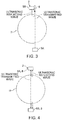
FIG. 4 shows the third arrangement example of theultrasonic transducers 5 and theultrasonic sensors 6 in case of detecting both an ultrasonic transmission wave, which has been transmitted through the first inspection area I1, and an ultrasonic reflected wave, which has been reflected in the first inspection area I1, by theultrasonic inspection unit 2 shown inFIG. 1 . - As shown in
FIG. 4 , the firstultrasonic transducer 5A can be disposed at a position opposed to the secondultrasonic transducer 5B across the first inspection area I1. In this case, an ultrasonic wave which has been oscillated from one of the firstultrasonic transducer 5A and the secondultrasonic transducer 5B, and subsequently has been transmitted through the first inspection area I1 can be detected by the other of the firstultrasonic transducer 5A and the secondultrasonic transducer 5B. That is, the other of the firstultrasonic transducer 5A and the secondultrasonic transducer 5B can be used as theultrasonic sensor 6. - When the first
ultrasonic transducer 5A is also used as theultrasonic sensor 6, an ultrasonic wave which has been oscillated from the firstultrasonic transducer 5A and subsequently has been reflected in the first inspection area I1 can be detected by the firstultrasonic transducer 5A which also functions as theultrasonic sensor 6. - Similarly, when the second
ultrasonic transducer 5B is also used as theultrasonic sensor 6, an ultrasonic wave which has been oscillated from the secondultrasonic transducer 5B and subsequently has been reflected in the first inspection area I1 can be detected by the secondultrasonic transducer 5B which also functions as theultrasonic sensor 6. - When the first inspection area I1 is large, the first inspection area I1 may be divided into subareas, and then the
ultrasonic transducers 5 and theultrasonic sensors 6 may be disposed so that the first inspection area I1 can be covered. In other words, the first inspection areas I1 may be overlapped with each other, and then at least oneultrasonic transducer 5 and at least oneultrasonic sensor 6 may be disposed per one first inspection area I1. In that case, ultrasonic inspection can be also performed based on ultrasonic waveforms obtained from each overlapped common area. - As the
ultrasonic sensor 6, an optical fiber sensor which does not oscillate an ultrasonic wave but only detects an ultrasonic wave can be used, besides an ultrasonic transducer which can transmit and receive an ultrasonic wave. Examples of an optical fiber sensor include an FBG sensor and a PS-FBG (Phase-shifted FBG) sensor. The PS-FBG is an FBG in which a local phase shift has been introduced into a periodic change of the refractive index. - When an optical fiber sensor is used as the
ultrasonic sensor 6, necessary optical elements and a light source which makes laser light incident in the optical fiber sensor are coupled to the optical fiber sensor. A signal, representing an ultrasonic waveform, detected by an optical fiber sensor may be transmission light or reflected light through or from the optical fiber sensor. -
FIG. 5 is a circuit diagram showing an example of an optical signal circuit for outputting a physical quantity, measured by anoptical fiber sensor 10, as an optical signal of transmission light. - When the
optical fiber sensor 10, such as an FBG sensor or a PS-FBG sensor, is attached to an object as shown inFIG. 5 , the wavelength distribution of transmission light and the wavelength distribution of reflected light from theoptical fiber sensor 10 each changes according to displacement arising in the object. - Therefore, when a
light source 11 is coupled to one end of theoptical fiber sensor 10 while aphotodetector 12 is coupled to the other end of theoptical fiber sensor 10, a displacement amount of the object can be detected as a change amount in wavelength of transmission light from theoptical fiber sensor 10, detected by thephotodetector 12. - That is, a displacement amount of the object is converted into a change amount in the wavelength of the transmission light from the
optical fiber sensor 10, and an optical signal is output, as transmission light of which wavelength changes, from theoptical fiber sensor 10. - Therefore, when the
optical fiber sensor 10 is disposed at a position at which an ultrasonic wave should be detected, it becomes possible to detect an ultrasonic waveform as a waveform of wavelength vibration of transmission light from theoptical fiber sensor 10 since vibration of minute displacement of the structural object O due to the ultrasonic wave is converted into the vibration of the wavelength of the transmission light. As a matter of course, desired optical elements, such as an optical filter for removing noise of an optical signal, may also be coupled. -
FIG. 6 is a circuit diagram showing an example of an optical signal circuit for outputting a physical quantity, measured by anoptical fiber sensor 10, as an optical signal of reflected light. - When an
optical circulator 13 is coupled to one end of theoptical fiber sensor 10, and then thelight source 11 is coupled to the input port of theoptical circulator 13 while thephotodetector 12 is coupled to the output port of theoptical circulator 13 as shown inFIG. 6 , reflected light from theoptical fiber sensor 10 can be detected by thephotodetector 12. - Therefore, a displacement amount of the object can be detected as a change amount in wavelength of the reflected light from the
optical fiber sensor 10, detected by thephotodetector 12. That is, a displacement amount of the object is converted into a change amount in the wavelength of the reflected light from theoptical fiber sensor 10, and an optical is output from theoptical fiber sensor 10 as reflected light of which wavelength changes. - Therefore, when the
optical fiber sensor 10 is disposed at a position at which an ultrasonic wave should be detected, it becomes possible to detect an ultrasonic waveform as a waveform of wavelength vibration of reflected light from theoptical fiber sensor 10 since vibration of minute displacement of the structural object O due to the ultrasonic wave is converted into the vibration of the wavelength of the reflected light. As a matter of course, desired optical elements, such as an optical filter for removing noise of an optical signal, may also be coupled. - As described above, the
ultrasonic inspection unit 2 detects at least one ultrasonic waveform in the first inspection area I1 by theultrasonic sensor 6 or theultrasonic sensors 6, such as theoptical fiber sensor 10 or theoptical fiber sensors 10. Meanwhile the strainamount detection unit 3 measures strain amounts of thesecond inspection area 12. - The strain
amount detection unit 3 is composed of the at least onestrain sensor 8, for detecting strain amounts of thesecond inspection area 12, and necessary circuit elements according to a kind of eachstrain sensor 8. Although a strain gauge may be used as thestrain sensor 8, the above-mentionedoptical fiber sensor 10 may be also used as thestrain sensor 8 with high sensitivity. - Specifically, when the
optical fiber sensor 10 is attached to thesecond inspection area 12, strain amounts in thesecond inspection area 12 can be output as an optical signal consisting of transmission light or reflected light from theoptical fiber sensor 10 since the light transmission characteristic and light reflection characteristic of theoptical fiber sensor 10 change according to the strain amounts in thesecond inspection area 12. - In this case, adopting known techniques, such as use of a wide band laser light, series coupling of the
optical fiber sensors 10 in which lights in different wavelength bands are transmitted or reflected, and multiplexing of optical signals output from theoptical fiber sensors 10, makes it possible to obtain optical signals representing strain amounts and positions at which strain has arisen in thesecond inspection area 12. - As mentioned above, the
ultrasonic inspection unit 2 performs ultrasonic inspection of the platy first inspection area I1 having no bent portion. Therefore, eachultrasonic transducer 5 and eachultrasonic sensor 6 of theultrasonic inspection unit 2 are attached to the platy first inspection area I1 with no bent portion. - On the other hand, the strain
amount detection unit 3 measures strain amounts in thesecond inspection area 12 including at least one bent platy portion. Therefore, eachstrain sensor 8 of the strainamount detection unit 3 is attached to thesecond inspection area 12 including the at least one bent platy portion. - The reason why the ultrasonic inspection is performed for the platy first inspection area I1 with no bent portion while strain amounts are measured in the
second inspection area 12 including at least one bent platy portion is as follows. An ultrasonic wave, such as a Lamb wave, has advantage that inspection can be carried out for a wide area compared with inspection of strain amounts since the ultrasonic wave propagates in a wider range. - Meanwhile, an ultrasonic wave has a disadvantage that inspection with sufficient accuracy cannot be performed for a portion having a complicated shape since the ultrasonic wave does not propagate with sufficient strength unless its medium has a flat surface or a sufficiently small curvature.
- On the contrary, the
strain sensor 8 has advantage that strain amounts of an object can be detected even when the object has a complicated shape. Meanwhile, thestrain sensor 8 has a disadvantage that thestrain sensor 8 can detect strain amounts only in a narrow range compared with that in ultrasonic inspection. - Accordingly, when a Lamb wave is used as an ultrasonic wave in particular, a rational method for determining inspection areas with taking advantage of the characteristics of the respective physical quantities is to determine an area including at least one plate-like bent portion as the
second inspection area 12 and a plate-like area, having no bent portion, wider than thesecond inspection area 12, as the first inspection area I1, based on the characteristic of a Lamb wave that a Lamb wave propagates in a wider range compared with a range in which a change in strain amount propagates although an attenuation amount in amplitude is large in a bent plate-like portion compared with that of a change in strain amount, and the characteristic of a change in strain amount that an attenuation amount in amplitude is small in a bent plate-like portion compared with that of a Lamb wave although a change in strain amount propagates in a narrower range compared with a range in which a Lamb wave propagates. -
FIG. 7 is a perspective view showing an example of theultrasonic transducers 5, theultrasonic sensors 6 and thestrain sensor 8 attached to an aircraft structural object O1. - As exemplified by
FIG. 7 , theultrasonic transducers 5, theultrasonic sensors 6 and thestrain sensor 8 can be attached to the aircraft structural object O1 composed of a panel O2 and a stringer O3, having a hat-shaped cross section, for reinforcing the panel O2. The panel O2 has a flat plate-like structure or a plate-like structure having a small curvature. - Therefore, the
ultrasonic transducers 5 and theultrasonic sensors 6 can be attached to the panel O2 so that ultrasonic inspection can be performed for the first inspection area I1 of the panel O2. Meanwhile, the hat-shaped stringer O3 has a complicated shape including bent plate-like portions. Therefore, thestrain sensor 8 can be attached to the hat-shaped stringer O3 so that strain amounts can be measured in thesecond inspection area 12 of the hat-shaped stringer O3. - In the example shown in
FIG. 7 , the firstoptical fiber sensors 10A are attached, as theultrasonic sensors 6, on the panel O2 while the secondoptical fiber sensor 10B is attached, as thestrain sensor 8, on the hat-shaped stringer O3 on which a large load applies compared with that applied on the panel O2. In addition, theultrasonic transducers 5 and theultrasonic sensors 6 are also disposed inside the hat-shaped stringer O3 so that ultrasonic inspection can be carried out for a part of the panel O2 lying inside the hat-shaped stringer O3. - As a matter of course, the
ultrasonic transducers 5, theultrasonic sensors 6 and thestrain sensor 8 may be attached to the aircraft structural object O1 including not only the hat-shaped stringer O3 but also a reinforcing member, such as an I-shaped stringer or a T- shaped stringer, which may have various shapes, attached to the panel O2, so that both the ultrasonic inspection and the strain amount measurement can be performed. -
FIG. 8 is a top view showing another example of theultrasonic transducers 5, theultrasonic sensors 6 and thestrain sensors 8 attached to an aircraft structural object O1 whileFIG. 9 is a side view of the aircraft structural object O1 shown inFIG. 8 . - The aircraft structural object O1 composing a typical fuselage of an aircraft has structure in which frames O4 and stringers O5 are attached on the panel O2 as exemplified by
FIG. 8 andFIG. 9 . Accordingly, plate-like areas each surrounded by the adjacent frames O4 and the adjacent stringers O5 are formed in the aircraft structural object O1 included in the fuselage. - Also in the above-described aircraft structural object O1 included in the fuselage, the
strain sensor 8 can be attached on each of the frames O4 and stringers O5, each having a complicated shape, on which loads are applied respectively while theultrasonic transducers 5 and theultrasonic sensors 6 can be attached to the portions of the panel O2 each surrounded by the frames O4 and the stringers O5. - Also in the example shown in
FIG. 8 , the firstoptical fiber sensors 10A are attached, as theultrasonic sensors 6, to the portions of the panel O2 surrounded by the frames O4 and the stringers O5 while the secondoptical fiber sensors 10B are attached, as thestrain sensors 8, on the upper surfaces of the frames O4 and the stringers O5 each having an inverted T-shaped cross section. - As described above, the
strain sensors 8 can be attached to the reinforcing members, such as stringers, spars, ribs and frames, while theultrasonic transducers 5 and theultrasonic sensors 6 can be attached to the panel. Thereby, SHM of the aircraft structural object O1 including the first inspection areas I1 and thesecond inspection areas 12 can be performed by ultrasonic inspection of the panel including the first inspection areas I1 and the strain amount measurement of the reinforcing members including thesecond inspection areas 12. This is similar for the structural object O other than the aircraft structural object O1. - When SHM of the structural object O having a structure in which at least one reinforcing member is attached to a panel is performed, each
strain sensor 8 may be attached to the at least one reinforcing member, not only by adhering thestrain sensor 8 on the surface of the at least one reinforcing member, but also, by embedding thestrain sensor 8 in the at least one reinforcing member as described in Japanese Patent Application PublicationJP 2017-173191 A strain sensor 8 between the at least one reinforcing member and the panel. - When the
strain sensor 8, such as theoptical fiber sensor 10, is sandwiched between a reinforcing member and a panel, strain amounts of the reinforcing member may be measured by embedding thestrain sensor 8 in the panel side. In that case, since strain amounts of both a part of the reinforcing member and a part of the panel can be measured by thestrain sensor 8, an area including the part of the reinforcing member and the part of the panel can also be set as thesecond inspection area 12. - SHM of the structural object O can be performed by obtaining at least one index expressing health of the structural object O. The
signal processing part 4 is a signal processing circuit which obtains the at least one index expressing the health of the structural object O including the first inspection areas I1 and thesecond inspection areas 12, based on ultrasonic waveforms from the first inspection areas I1, detected by theultrasonic sensors 6, and strain amounts of thesecond inspection areas 12, detected by thestrain sensors 8. - Each detection signal of ultrasonic waveform is output, as an electric signal or an optical signal, from the
ultrasonic sensor 6. On the other hand, each detection signal of strain amount of thesecond inspection area 12 is also output, as an electric signal or an optical signal, from thestrain sensor 8. Therefore, thesignal processing part 4 can be composed of thephotodetectors 12, A/D (analog-to-digital) converters and electric circuitry, such as a computer. - Each
photodetector 12 converts an optical signal, as shown inFIG. 5 and FIG. 6 , into an electric signal. Each A/D converter converts an analog electric signal into a digital electric signal. The electric circuitry performs signal processing of digital electric signals. In addition, optical elements, such as an optical filter, for signal processing of optical signals may be included in thesignal processing part 4. - Concrete examples of a useful index, expressing health for SHM of the structural object O, include whether damage has arisen in the structural object O, whether a crack has arisen in the structural object O, whether delamination has arisen in the structural object O made of an FRP, an index expressing the degree of a defect which has arisen in the structural object O, and the like. Therefore, the
signal processing part 4 can be configured to obtain at least one of these indexes. - The
signal processing part 4 can obtain inspection information on SHM, including an index or indexes each showing health, by desired signal processing of at least one ultrasonic waveform signal detected from the first inspection area I1 and at least one strain amount of thesecond inspection area 12. - For example, when an ultrasonic waveform detected from the first inspection area I1 is analyzed to detect an abnormal change in the ultrasonic waveform, the existence of a defect, such as damage, a crack or delamination, in the first inspection area I1 can be detected. As a more concrete example, a signal waveform obtained by signal processing, such as averaging processing, filter processing for noise removal using an LPF (Low Pass Filter), an HPF (High Pass Filter) and the like, envelope detection processing, and frequency analysis processing by Fourier transform processing and/or wavelet transformation, of an ultrasonic waveform signal detected from the first inspection area I1 can be compared to a reference waveform which is a signal waveform in a case where no defect exists in the first inspection area I1.
- Then, when the signal waveform detected from the first inspection area I1 has deviated from the reference waveform with exceeding a threshold value, it can be determined that a defect has arisen in the first inspection area I1 and the waveform of the ultrasonic wave which has passed through the first inspection area I1 has changed due to the generated defect.
- Moreover, when a waveform of an ultrasonic reflected wave has been detected from the first inspection area I1, a time at which an ultrasonic wave was oscillated from the
ultrasonic transducer 5 towards the first inspection area I1 can be notified from the control circuit 7 of theultrasonic transducer 5 to thesignal processing part 4. Thereby, a position of a defect can also be estimated by measuring an elapsed time from the time, at which the ultrasonic wave was oscillated from theultrasonic transducer 5, until a peak time of the reflected wave detected by theultrasonic sensor 6. - When the structural object O is the aircraft structural object O1, the first inspection area I1 is vibrated, due to an applied aerodynamic load, during a flight of the aircraft. The vibration pattern of the first inspection area I1 during a flight of the aircraft dynamically changes according to momently changing various flight conditions including the speed and the altitude of the aircraft.
- For that reason, at least one feature amount expressing vibration of the first inspection area I1 according to flight conditions of an aircraft can be obtained beforehand. Thereby, it becomes possible to perform ultrasonic inspection during a flight of the aircraft by signal processing for canceling the vibration of the first inspection area I1 due to the flight of the aircraft from vibration of each ultrasonic wave.
- Since the vibration according to flight conditions of an aircraft changes for every flight condition, the feature amount or feature amounts showing the vibration may be obtained not only by simulations and/or examinations but by a machine learning method statistically. This is similar in a case where the structural object O is a mobile object, such as an automobile, other than the aircraft structural objects O1.
- On the other hand, when changes in strain amounts of the
second inspection area 12 are analyzed, the existence of a defect, such as damage, a crack or delamination, can be detected in thesecond inspection area 12. As a more concrete example, each measured value of strain amount in thesecond inspection area 12 can be compared to a reference value of strain amount in a case where no defect exists in thesecond inspection area 12. - When at least one measured value of strain amount has deviated from the reference value of strain amount with exceeding a threshold value, it can be determined that a defect has arisen in the
second inspection area 12 and the at least one strain amount in thesecond inspection area 12 has increased due to the generated defect. - When the structural object O is the aircraft structural object O1, the
second inspection area 12 deforms, due to an applied aerodynamic load, during a flight of an aircraft, and thereby the strain amounts of thesecond inspection area 12 change. The strain amounts of thesecond inspection area 12 during a flight of an aircraft also change dynamically according to momently changing various flight conditions including the speed and the altitude of the aircraft, similarly to the vibration pattern in the first inspection area I1. - For that reason, change amounts in strain amounts in the
second inspection area 12 according to flight conditions of an aircraft can be obtained beforehand. Thereby, it becomes possible to extract strain amounts in thesecond inspection area 12 only due to a defect during a flight of the aircraft by signal processing for canceling the change amounts in strain amounts in thesecond inspection area 12 due to a flight of the aircraft from strain amounts in thesecond inspection area 12 measured by thestrain sensor 8 or thestrain sensors 8. - Since the change amounts in strain amounts in the
second inspection area 12 according to flight conditions of an aircraft change for every flight condition, similarly to vibration, the change amounts in strain amounts may be obtained not only by simulations and/or examinations but by a machine learning method statistically. This is similar in a case where the structural object O is a mobile object, such as an automobile, other than the aircraft structural objects O1. - When the
strain sensor 8 is theoptical fiber sensor 10, each measured value of strain amount in thesecond inspection area 12 is obtained by analyzing a waveform signal, showing a wavelength spectrum of a transmission light or a reflected light from theoptical fiber sensor 10, output from thephotodetector 12. That is, each measured value of strain amount in thesecond inspection area 12 is expressed as a change amount in peak wavelength of a signal waveform showing a wavelength spectrum of a transmission light or a reflected light output from theoptical fiber sensor 10. - Therefore, signal processing, such as averaging, filter processing and/or frequency analysis processing, similar to signal processing of an ultrasonic waveform signal, may be performed to each signal output from the
photodetector 12. - When strain gauges are disposed at different positions, or when the
optical fiber sensor 10 or theoptical fiber sensors 10 can detect strain amounts at different positions, plural strain amounts at positions in thesecond inspection area 12 are measured. Therefore, not only the existence of a defect but also a position of the defect can be obtained based on the strain amounts of thesecond inspection area 12. In addition, when a temporal change in strain amount is measured, it becomes possible to grasp the degree in development of a defect. - When the
second inspection area 12 from which the strain amounts are to be measured is sufficiently near a defect which has arisen in the first inspection area I1 which is the target of the ultrasonic inspection, the measured values of the strain amounts in thesecond inspection area 12 also changes slightly due to the defect which has arisen in the first inspection area I1. Therefore, the measured values of the strain amounts in thesecond inspection area 12 also allows estimation of the existence of a defect in the first inspection area I1 as well as in thesecond inspection area 12. - Accordingly, the
signal processing part 4 can have a function to determine whether there is possibility that a defect has arisen in the first inspection area I1, based on the measured values of the strain amounts in thesecond inspection area 12 detected by thestrain sensor 8 or thestrain sensors 8. - More specifically, when a slight change in strain amount according to which it is determined that no defect has arisen in the
second inspection area 12 has been detected by threshold value processing, it can be determined that a detect may have arisen at a position in the first inspection area I1 near a position where the slight change in strain amount has been detected. - When the
optical fiber sensor 10 is used as thestrain sensor 8, the length of theoptical fiber sensor 10 becomes long since the strain amounts in thesecond inspection area 12 having a wider range should be measured by the commonoptical fiber sensor 10 as exemplified byFIG. 7 andFIG. 8 , and thereby only a part of theoptical fiber sensor 10 may be near the first inspection area I1, or a plurality of parts of theoptical fiber sensor 10 may be near the different first inspection areas I1 respectively. This is similar in a case where many strain gauges are disposed, as thestrain sensors 8, at different positions. - Accordingly, the
second inspection area 12 may be segmented into a plurality of areas so that it can be determined whether there is possibility that a defect has arisen in the first inspection area I1, based on the strain amounts in the nearest segmented area to the first inspection area I1 out of the segmented areas. - As a concrete example, when one common
optical fiber sensor 10 is disposed zigzag along the two ridgelines in the mountain fold side and the two ridgelines in the valley fold side in the outside of the hat-shaped stringer O3 as shown inFIG. 7 , two portions of theoptical fiber sensor 10 disposed along the two ridgelines in the valley fold side are adjacent to the portions of the panel O2 in both sides of the hat-shaped stringer O3 and the portion of the panel O2 inside the hat-shaped stringer O3. - Accordingly, the
second inspection area 12 can be divided into the first area R1 along the ridgeline in one valley fold side of the hat-shaped stringer O3, the second area R2 along the ridgeline in the other valley fold side of the hat-shaped stringer O3, and the other remaining area R3. - Then, when at least one strain amount in one of the first area R1 and the second area R2 along the ridgelines in the valley fold side has increased to a degree in which it is determined that no defect has arisen in any of the first area R1 and the second area R2, it can be determined that a defect may have arisen in one of the first inspection area I1, defined as the portion of the panel O2 in the nearer one side of the hat-shaped stringer O3 to the one of the first area R1 and the second area R2, and the first inspection area I1, defined as the portion of the panel O2 inside the hat-shaped stringer O3.
- As another concrete example, when the
optical fiber sensor 10 or theoptical fiber sensors 10 are disposed in grid pattern as shown inFIG. 8 , thesecond inspection area 12 set in the frames O4 and the stringers O5 can be divided into areas at the respective positions where theoptical fiber sensors 10 intersect with each other. - Then, when at least one strain amount has increased in a certain area out of the divided areas included in the
second inspection area 12, to a degree in which it is determined that no defect has arisen in the certain area, it can be determined that a defect may have arisen in at least one of the two first inspection areas I1 defined as rectangular areas of the panel O2 formed in both sides of the frame O4 or the stringer O5 whose strain amount or strain amounts have increased. - Each strain amount can be continuously measured by the
optical fiber sensor 10 as long as light is entering theoptical fiber sensor 10 from thelight source 11. Alternatively, each strain amount can be continuously measured by an electrical resistance type strain gauge which detects the strain amount as a change in electrical resistance as long as a voltage is being applied from a power supply to the strain gauge. - Accordingly, the inspection, such as detection of a defect, in the
second inspection area 12 by measuring the strain amounts in thesecond inspection area 12, and the determination of whether a defect may have arisen in the first inspection area I1 can be continued by keeping eachstrain sensor 8 the operating state. - Meanwhile, in order to perform an ultrasonic inspection of the first inspection area I1, it is necessary to oscillate an ultrasonic wave from the
ultrasonic transducer 5. When an ultrasonic wave is intermittently oscillated at a constant oscillation interval set short, an ultrasonic inspection can be also intermittently performed. Nevertheless, it is desired to set an oscillation interval of an ultrasonic wave to be long in order to decrease power consumption. - Accordingly, each ultrasonic wave may be manually oscillated by operation of an
input device 7A coupled to the control circuit 7 of theultrasonic transducer 5, or automatically oscillated at a constant interval determined so that the power consumption can be reduced. Instead, the determination of whether there is possibility that a defect has arisen in the first inspection area I1, by measuring the strain amounts in thesecond inspection area 12, can be continued. - Then, the ultrasonic inspection of the first inspection area I1 can be performed just when it has been determined that a defect may have arisen in the first inspection area I1. Thereby, the demerit of ultrasonic inspection that uninterrupted inspection requires energy can be compensated by inspection of the strain amounts which is easy to be carried out continuously.
- The ultrasonic inspection in the first inspection area I1 based on a measurement result of the strain amounts in the
second inspection area 12 can be started automatically. In that case, what is necessary is to output control signals from thesignal processing part 4 to the control circuit 7 of theultrasonic transducer 5 so that the control circuit 7 controls theultrasonic transducer 5 to oscillate at least one ultrasonic wave toward the first inspection area I1 in case where thesignal processing part 4 has determined that a defect may have arisen in the first inspection area I1 based on the strain amounts of thesecond inspection area 12 detected by thestrain sensor 8 or thestrain sensors 8. - That is, a determination result by the
signal processing part 4 that a defect may have arisen in the first inspection area I1 can be used as a trigger for oscillating an ultrasonic wave from theultrasonic transducer 5 to the first inspection area I1. - As a concrete example, when the strain amounts of the hat-shaped stringer O3 shown in
FIG. 7 have increased slightly, it can be determined that a defect may have arisen in at least one of the portions of the panel O2 in both sides of the hat-shaped stringer O3, and then ultrasonic inspection of one or both of the portions of the panel O2 in both sides of the hat-shaped stringer O3 can be performed. - As another concrete example, when the strain amounts of the frame O4 or the stringer O5 shown in
FIG. 8 have locally increased slightly, it can be determined that a defect may have arisen in at least one of rectangular portions of the panel O2 in both sides of a portion of the frame O4 or the stringer O5 in which the strain amounts have increased, and then ultrasonic inspection of the rectangular portions of the panel O2 in both sides of the portion of the frame O4 or the stringer O5 can be performed. - As mentioned above, ultrasonic inspection based on an ultrasonic reflected wave in the first inspection area I1 allows calculation of a position of a defect in the first inspection area I1, based on a peak time of the ultrasonic reflected wave, acoustic velocity and the like. On the contrary, in case of ultrasonic inspection based on only a waveform of an ultrasonic wave which has been transmitted through the first inspection area I1, it is difficult to obtain a position of a defect in the first inspection area I1, except when many
ultrasonic transducers 5 andultrasonic sensors 6 are densely disposed. - Nevertheless, the strain amounts in the
second inspection area 12 sometimes change due to the influence of a defect which has arisen in the first inspection area I1 which is a target of ultrasonic inspection, as mentioned above. It is considered that a distribution of the strain amounts which have changed in thesecond inspection area 12 changes depending on a position of a defect which has arisen in the first inspection area I1. - Specifically, it is considered that, the closer a position in the
second inspection area 12 is to a position of a defect which has arisen in the first inspection area I1, the larger a change amount in strain becomes. - For that reason, when the
signal processing part 4 has determined that a defect has arisen in the first inspection area I1 based on at least one ultrasonic waveform detected by theultrasonic sensor 6, as a result of ultrasonic inspection for the first inspection area I1, a defect arising area in the first inspection area I1 can be estimated based on a distribution of the strain amounts of thesecond inspection area 12 detected by thestrain sensor 8 or thestrain sensors 8, regardless of whether it has been previously determined that a defect may have arisen in the first inspection area I1 based on the strain amounts in thesecond inspection area 12. - Concrete examples of easy analysis processing based on a strain distribution include processing which narrows a defect arising area down to an area in the first inspection area I1 which is the nearest to the position of the
second inspection area 12 at which the strain amount becomes a peak, compared with the other positions in thesecond inspection area 12. In this case, an area having a sector form or a shape derived by cutting off a part from a sector form can be extracted from the first inspection area I1 as a defect arising area, for example. - Concrete examples of complicated analysis processing based on a strain distribution include processing which estimates a defect arising area based on an actually measured strain distribution and reference information, stored in a storage, including a table or a function representing a relationship between positions of defects in the first inspection area I1 and distributions of the strain amounts of the
second inspection area 12 obtained by repeating simulations and/or examinations. In this case, the estimation accuracy can be improved by a machine learning method or the like. - Next, a method of structural health monitoring (SHM) of the structural object O using the structural
health monitoring system 1 will be described. -
FIG. 10 is a flow chart showing an example of a flow for SHM of the structural object O using the structuralhealth monitoring system 1 shown inFIG. 1 . - Firstly, in step S1, ultrasonic inspection of the plate-like first inspection areas I1 each including no bent portion and measurement of the strain amounts in the
second inspection areas 12 each including at least one bent plate-like portion are performed. - Specifically, the
ultrasonic inspection unit 2 shown inFIG. 1 obtains at least one of waveforms of ultrasonic waves which have been transmitted through the first inspection areas I1 and waveforms of ultrasonic reflected waves which have been reflected in the first inspection areas I1. On the other hand, the strain amounts in thesecond inspection areas 12 are measured by the strainamount detection unit 3. - More specifically, an electric signal is applied to each
ultrasonic transducer 5 from the control circuit 7 of theultrasonic inspection unit 2 manually by operating theinput device 7A or automatically at a constant interval. Thereby, ultrasonic waves are oscillated from theultrasonic transducers 5 disposed in the structural object O, such as the aircraft structural object O1, as exemplified inFIG. 7 to FIG. 9 , for example. - The oscillated ultrasonic waves propagate the platy first inspection areas I1 with no bent portion, such as the panel O2 of the aircraft structural object O1, and then at least one of the waveforms of the ultrasonic transmission waves which have been transmitted through the first inspection areas I1 and the waveforms of the ultrasonic reflected waves which have been reflected in the first inspection areas I1, as exemplified by
FIG. 2 to FIG. 4 , are detected by theultrasonic sensors 6, such as the firstoptical fiber sensors 10A as shown inFIG. 7 or8 . - When the
ultrasonic sensor 6 is theoptical fiber sensor 10 as exemplified byFIG. 5 or FIG. 6 , a broadband laser light or the like is output from thelight source 11 to theoptical fiber sensor 10. Then, a waveform signal of an ultrasonic wave is output as an optical signal from theoptical fiber sensor 10. - Meanwhile, when the
ultrasonic sensor 6 is the ultrasonic transducer as exemplified inFIG. 4 , a waveform signal of an ultrasonic wave is output as an electric signal. The waveform signal of the ultrasonic wave detected by theultrasonic sensor 6 is output from theultrasonic sensor 6 to thesignal processing part 4. - On the other hand, the strain amounts in the
second inspection areas 12 are measured by thestrain sensors 8 of the strainamount detection unit 3 shown inFIG. 1 . As a concrete example, the strain amounts in thesecond inspection areas 12, such as the hat-shaped stringer O3, or the frames O4 and the stringers O5, each including at least one bent platy portion are measured by thestrain sensors 8, such as the secondoptical fiber sensors 10B, disposed in the structural object O, such as the aircraft structural object O1, as exemplified byFIG. 7 to FIG. 9 . - When the
strain sensor 8 is theoptical fiber sensor 10 as exemplified byFIG. 5 or FIG. 6 , a broadband laser light or the like is output from thelight source 11 to theoptical fiber sensor 10. Then, a detection signal of at least one strain amount is output, as an optical signal, from theoptical fiber sensor 10. - Meanwhile, when the
strain sensor 8 is an electric resistance type strain gauge, a detection signal of a strain amount is output as an electric signal. The detection signal of at least one strain amount detected by thestrain sensor 8 is output from thestrain sensor 8 to thesignal processing part 4. - Next, the
signal processing part 4 obtains at least one index expressing the health of the structural object O including the first inspection areas I1 and thesecond inspection areas 12, based on the ultrasonic waveforms detected by theultrasonic sensors 6 and the strain amounts in thesecond inspection areas 12 detected by thestrain sensors 8. As a concrete example, whether a defect has arisen in the first inspection areas I1 and thesecond inspection areas 12 can be obtained as an index expressing the health. - For that purpose, in step S2, it is determined whether each strain amount in the
second inspection areas 12 has deviated from a reference strain amount. When it has been determined that any strain amount in thesecond inspection areas 12 has not deviated from the reference strain amount, it is determined whether each ultrasonic waveform acquired from the first inspection areas I1 has deviated from a reference ultrasonic waveform, in step S3. - Moreover, when it has been determined that at least one strain amount in the
second inspection areas 12 has deviated from the reference strain amount, it is also determined whether each ultrasonic waveform acquired from the first inspection areas I1 has deviated from the reference ultrasonic waveform, in step S4. - Note that, the order of the determination of the existence of a variation in each ultrasonic waveform and the determination of the existence of a variation in each strain amount is flexible, and the order may be reversed or these determinations may be performed simultaneously by parallel processing.
- When it has been determined that any of the ultrasonic waveforms acquired from the first inspection areas I1 and any of the strain amounts in the
second inspection areas 12 have not deviated from the reference waveform and the reference strain amount respectively, it can be determined that any of the first inspection areas I1 and any of thesecond inspection areas 12 have no defect. - Alternatively, it can be determined that the first inspection areas I1 have a defect when it has been determined that at least one ultrasonic waveform acquired from the first inspection areas I1 has deviated from the reference waveform while it can be determined that the
second inspection areas 12 have a defect when it has been determined that at least one strain amount in thesecond inspection areas 12 has deviated from the reference strain amount. - Therefore, when it has been determined that at least one ultrasonic waveform acquired from the first inspection areas I1 and at least one strain amount in the
second inspection areas 12 have deviated from the reference waveform and the reference strain amount respectively, it can be determined that both the first inspection areas I1 and thesecond inspection areas 12 have defects. - As described above, the structural
health monitoring system 1 and the method of monitoring structural health classify the structural object O into areas for ultrasonic inspection and areas for measuring strain amounts according to a shape of the structural object O, and perform SHM based on both of changes in ultrasonic waveforms and changes in strain amounts. - Accordingly, according to the structural
health monitoring system 1 and the method of monitoring structural health, the restriction in SHM can be reduced and the inspection accuracy can be improved, compared with a case of SHM only by ultrasonic inspection or a case of SHM only by measuring strain amounts. - Specifically, SHM can be performed for the plate-like first inspection area I1, having no bent portion, by ultrasonic inspection even without disposing the
strain sensors 8 comprehensively. In other words, detection omission of a defect due to lack of arrangement of thestrain sensors 8 can be reduced. - On the contrary, as for the
second inspection area 12 including at least one bent plate-like portion, detection omission of a defect due to insufficient intensity of an propagating ultrasonic wave for detection of a defect can be reduced by SHM based on strain amounts. - That is, it becomes to possible to detect a defect, which cannot be detected by SHM only by measuring strain amounts, and a defect, which cannot be detected only by ultrasonic inspection, and thereby usage restrictions in the conventional SHM system can be reduced.
- Moreover, since it becomes unnecessary to dispose
many strain sensors 8 comprehensively in the plate-like first inspection area I1 having no bent portion, the number of thestrain sensors 8, the data size of measured strain amounts and a signal processing amount can be remarkably reduced compared with those in the conventional SHM only by measurement of strain amounts. - In particular, when the structural object O is the aircraft structural object O1, weight saving, which is important for an aircraft, can be attained by reducing the number of the
strain sensors 8, the scale of a signal processing circuit, and the like. -
- 1
- structural health monitoring system
- 2
- ultrasonic inspection unit
- 3
- strain amount detection unit
- 4
- signal processing part
- 5
- ultrasonic transducer
- 5A
- first ultrasonic transducer
- 5B
- second ultrasonic transducer
- 6
- ultrasonic sensor
- 6A
- first ultrasonic sensor
- 6B
- second ultrasonic sensor
- 7
- control unit
- 7A
- input device
- 8
- strain sensor
- 10
- optical fiber sensor
- 10A
- first optical fiber sensor
- 10B
- second optical fiber sensor
- 11
- light source
- 12
- photodetector
- 13
- optical circulator
- 11
- first inspection area
- 12
- second inspection area
- O
- structural object
- O1
- aircraft structural object
- O2
- panel
- O3
- stringer
- O4
- frames
- O5
- stringer
- R1
- first area
- R2
- second area
- R3
- remaining area
Claims (12)
- A structural health monitoring system (1) that is configured to monitor structural health of a structural object (O) having a plate-like first inspection area (I1) and a second inspection area (12), the first inspection area (I1) having no bent portion,
the second inspection area (12) including a bent plate-like portion, the structural health monitoring system (1) comprising:- an ultrasonic transducer (5) that is configured to oscillate an ultrasonic wave to the first inspection area (I1);- an ultrasonic sensor (6) that is configured to detect a waveform of at least one of a transmission wave of the ultrasonic wave and a reflected wave of the ultrasonic wave, the transmission wave having been transmitted through the first inspection area (I1), the reflected wave having been reflected in the first inspection area (I1);- a strain sensor (8) that is configured to detect a strain amount of the second inspection area (12); and- a signal processing part (4) that is configured to obtain at least one index, representing health of the structural object (O) including the first inspection area (I1) and the second inspection area (12), based on the waveform detected by the ultrasonic sensor (6) and the strain amount detected by the strain sensor (8). - The system (1) according to claim 1,
wherein the at least one index includes at least one of whether the structural object (O) has been damaged, whether the structural object (O) has cracked, whether the structural object (O) made of fiber reinforced plastic has delaminated, and an index expressing degree of a defect that has arisen on the structural object (O). - The system (1) according to claim 1 or 2,
wherein the signal processing part (4) is configured to determine whether there is a possibility that a defect has arisen in the first inspection area (I1), based on the detected strain amount in the second inspection area (12). - The system (1) according to any one of claims 1 to 3,
wherein the signal processing part (4) is configured to segment the second inspection area (12) into areas, and to determine whether there is the possibility that a defect has arisen in the first inspection area (I1), based on the strain amount in a selected area out of the segmented areas, the selected area being closest to the first inspection area (I1). - The system (1) according to any one of claims 1 to 4,
further comprising:
a control circuit (7) that is configured to control the ultrasonic transducer (5) to oscillate the ultrasonic wave toward the first inspection area (I1) when the signal processing part (4) has determined that there is the possibility that a defect has arisen in the first inspection area (I1). - The system (1) according to any one of claims 1 to 5,
wherein the signal processing part (4) is configured to estimate an area in which a defect has arisen, based on the strain amount, when it has been determined that the defect has arisen in the first inspection area (I1), based on the waveform. - An aircraft structural object (O1) comprising:
a structural health monitoring system (1) according to any one of claims 1 to 6. - A method of monitoring the structural health of a structural object (O),
the method comprising:
using the structural health monitoring system (1) according to any one of claims 1 to 6. - A method of monitoring structural health of a structural object (O) having a plate-like first inspection area (I1) and a second inspection area (12), the first inspection area (I1) having no bent portion, the second inspection area (12) including a bent plate-like portion, the method comprising:- oscillating an ultrasonic wave to the first inspection area (I1) by an ultrasonic transducer (5);- detecting a waveform of at least one of a transmission wave of the ultrasonic wave and a reflected wave of the ultrasonic wave, the transmission wave having been transmitted through the first inspection area (I1), the reflected wave having been reflected in the first inspection area (I1), the waveform being detected by an ultrasonic sensor (6);- detecting a strain amount of the second inspection area (12) by a strain sensor (8); and- obtaining an index, representing health of the structural object (O) including the first inspection area (I1) and the second inspection area (12), based on the waveform detected by the ultrasonic sensor (6) and the strain amount detected by the strain sensor (8).
- The method according to claim 8 or 9,
wherein the method is applied to a structural object (O) which includes an aircraft structural object (O1) having a panel (O2) and at least one reinforcing member (O3) attached to the panel (O2), the at least one reinforcing member (O3) including at least one of a stringer, a spar, a rib and a frame, the panel (O2) including the first inspection area (I1), the at least one reinforcing member (O3) including the second inspection area (12), the strain sensor (8) being attached to the at least one reinforcing member (O3), the ultrasonic transducer (5) and the ultrasonic sensor (6) being attached to the panel (O2). - The method according to any one of claims 8 to 10,
wherein the ultrasonic wave is a Lamb wave. - The method according to claim 11,
wherein an area including the bent plate-like portion is determined as the second inspection area (12) while a plate-like area, having no bent portion, larger than the second inspection area (12) is determined as the first inspection area (I1), the first and second inspection areas (I1, 12) being determined based on a characteristic of a Lamb wave and a variation in the strain amount that the Lamb wave propagates in a wider range than a range in which the variation in the strain amount propagates while a first attenuation amount in amplitude of the Lamb wave is larger than a second attenuation amount of the variation in the strain amount in the bent plate-like portion.
Applications Claiming Priority (1)
| Application Number | Priority Date | Filing Date | Title |
|---|---|---|---|
| JP2020056962A JP7387511B2 (en) | 2020-03-27 | 2020-03-27 | Structural health diagnosis system, structural health diagnosis method, and aircraft structure |
Publications (2)
| Publication Number | Publication Date |
|---|---|
| EP3885732A1 true EP3885732A1 (en) | 2021-09-29 |
| EP3885732B1 EP3885732B1 (en) | 2023-04-05 |
Family
ID=74625893
Family Applications (1)
| Application Number | Title | Priority Date | Filing Date |
|---|---|---|---|
| EP21157130.2A Active EP3885732B1 (en) | 2020-03-27 | 2021-02-15 | Structural health monitoring system |
Country Status (4)
| Country | Link |
|---|---|
| US (1) | US11656201B2 (en) |
| EP (1) | EP3885732B1 (en) |
| JP (1) | JP7387511B2 (en) |
| CN (1) | CN113447566B (en) |
Families Citing this family (1)
| Publication number | Priority date | Publication date | Assignee | Title |
|---|---|---|---|---|
| US20240310331A1 (en) * | 2022-07-15 | 2024-09-19 | Tda Research, Inc | Electromagnetic Inductive Coupling Analysis (EMICA) for on-board or in-lab detection of defects in thick or thin carbon fiber laminates |
Citations (6)
| Publication number | Priority date | Publication date | Assignee | Title |
|---|---|---|---|---|
| JP2016173336A (en) | 2015-03-18 | 2016-09-29 | 富士重工業株式会社 | Ultrasonic flaw detection system, ultrasonic flaw detection method and manufacturing method of aircraft component |
| JP2017173191A (en) | 2016-03-24 | 2017-09-28 | 株式会社Subaru | Composite material forming jig, composite material forming method, ultrasonic inspection system, ultrasonic inspection method, and aircraft structure |
| WO2017175692A1 (en) | 2016-04-06 | 2017-10-12 | 株式会社Subaru | Ultrasonic inspection system, ultrasonic inspection method, and aircraft structure |
| WO2018055827A1 (en) | 2016-09-26 | 2018-03-29 | 株式会社Subaru | Damage detection system and damage detection method |
| JP2018146368A (en) | 2017-03-03 | 2018-09-20 | 株式会社Subaru | Current observation system, method for observing current, and aircraft |
| US10401316B2 (en) * | 2017-05-23 | 2019-09-03 | Simmonds Precision Products, Inc. | Acoustic event monitoring for triggering of health scan of a structure |
Family Cites Families (7)
| Publication number | Priority date | Publication date | Assignee | Title |
|---|---|---|---|---|
| US5184516A (en) * | 1991-07-31 | 1993-02-09 | Hughes Aircraft Company | Conformal circuit for structural health monitoring and assessment |
| JP3944578B2 (en) * | 2003-06-17 | 2007-07-11 | 独立行政法人産業技術総合研究所 | Strain and AE measuring device using optical fiber sensor |
| JP5294687B2 (en) * | 2008-05-02 | 2013-09-18 | キヤノン株式会社 | Ultrasonic measuring device and control method thereof |
| JP5192939B2 (en) * | 2008-08-14 | 2013-05-08 | 三菱重工業株式会社 | Defect height estimation method by ultrasonic flaw detection |
| JP2010169558A (en) * | 2009-01-23 | 2010-08-05 | Hitachi Constr Mach Co Ltd | Ultrasonic measuring device |
| JP5586011B2 (en) * | 2010-03-18 | 2014-09-10 | 独立行政法人産業技術総合研究所 | FBG vibration detection system, apparatus using the system, and vibration detection method |
| JP7131967B2 (en) * | 2018-05-30 | 2022-09-06 | 株式会社Subaru | Optical inspection system, optical inspection method, and aircraft structure |
-
2020
- 2020-03-27 JP JP2020056962A patent/JP7387511B2/en active Active
- 2020-12-29 US US17/136,615 patent/US11656201B2/en active Active
-
2021
- 2021-01-26 CN CN202110104228.5A patent/CN113447566B/en active Active
- 2021-02-15 EP EP21157130.2A patent/EP3885732B1/en active Active
Patent Citations (8)
| Publication number | Priority date | Publication date | Assignee | Title |
|---|---|---|---|---|
| JP2016173336A (en) | 2015-03-18 | 2016-09-29 | 富士重工業株式会社 | Ultrasonic flaw detection system, ultrasonic flaw detection method and manufacturing method of aircraft component |
| JP2017173191A (en) | 2016-03-24 | 2017-09-28 | 株式会社Subaru | Composite material forming jig, composite material forming method, ultrasonic inspection system, ultrasonic inspection method, and aircraft structure |
| US20170276648A1 (en) * | 2016-03-24 | 2017-09-28 | Fuji Jukogyo Kabushiki Kaisha | Composite material molding jig, composite material molding method, ultrasonic test system, ultrasonic test method and aircraft structural object |
| WO2017175692A1 (en) | 2016-04-06 | 2017-10-12 | 株式会社Subaru | Ultrasonic inspection system, ultrasonic inspection method, and aircraft structure |
| WO2018055827A1 (en) | 2016-09-26 | 2018-03-29 | 株式会社Subaru | Damage detection system and damage detection method |
| US20190112072A1 (en) * | 2016-09-26 | 2019-04-18 | Subaru Corporation | Damage detection system and damage detection method |
| JP2018146368A (en) | 2017-03-03 | 2018-09-20 | 株式会社Subaru | Current observation system, method for observing current, and aircraft |
| US10401316B2 (en) * | 2017-05-23 | 2019-09-03 | Simmonds Precision Products, Inc. | Acoustic event monitoring for triggering of health scan of a structure |
Also Published As
| Publication number | Publication date |
|---|---|
| US11656201B2 (en) | 2023-05-23 |
| EP3885732B1 (en) | 2023-04-05 |
| CN113447566B (en) | 2025-04-29 |
| JP7387511B2 (en) | 2023-11-28 |
| US20210302372A1 (en) | 2021-09-30 |
| JP2021156721A (en) | 2021-10-07 |
| CN113447566A (en) | 2021-09-28 |
Similar Documents
| Publication | Publication Date | Title |
|---|---|---|
| EP2369334B1 (en) | System and method for damage diagnosis | |
| EP3112857B1 (en) | System comprising an aircraft structural object attached to an ultrasonic test system, and ultrasonic test method | |
| US8499632B1 (en) | Characterizing anomalies in a laminate structure | |
| EP3070467B1 (en) | Ultrasonic test system, ultrasonic test method and method of manufacturing aircraft part | |
| US8694269B2 (en) | Reducing the ringing of actuator elements in ultrasound based health monitoring systems | |
| US11226311B2 (en) | Ultrasonic inspection system, ultrasonic inspection method and aircraft structural object | |
| Grigg et al. | Acoustic emission source location in complex aircraft structures using three closely spaced sensors | |
| CN113390967B (en) | Nonlinear guided wave composite material damage positioning method based on trapezoidal array | |
| CN114646687B (en) | Surface stress detection method of carbon fiber composite plate based on ultrasonic critical refraction longitudinal wave | |
| JP2005326326A (en) | Strain measurement using optical fiber sensor and ultrasonic / AE detector | |
| CN116735714A (en) | A test method for voiding defects in steel box concrete shear walls | |
| EP3885732B1 (en) | Structural health monitoring system | |
| KR20120031674A (en) | System and apparatus for measuring non-linearity of ultrasonic wave | |
| JP2006132952A (en) | Movable FBG ultrasonic sensor | |
| Díaz Valdés et al. | A structural health monitoring system for laminated composites | |
| Birkelbach et al. | Integral structural health and load monitoring of a helicopter tail boom manufactured from aluminum sheet metal with support from frames and stringers by guided ultrasonic waves | |
| Saxena et al. | Viability of guided-wave ultrasound diagnostics for sharply curved composite structures | |
| Pommier-Budinger et al. | DAMAGE LOCALIZATION METHOD FOR THIN COMPOSITE STRUCTURES APPLICATION TO AN AIRCRAFT DOOR | |
| Nguyen et al. | Integrated health and corrosion monitoring systems in the aerospace industry | |
| Petculescu et al. | Monitoring of Safety Critical Composite | |
| Pommier-Budinger et al. | Damage location method for thin composites structures-application to an aircraft door | |
| Soutis et al. | Delamination detection in laminated composites using Lamb waves | |
| HONG et al. | STUDY ON MODE SWITCHING ALGORITHM AND DAMAGE EVALUATION FOR EFFICIENT AND PRECISION SHM USING SMART SENSOR | |
| KIYOSHIMA et al. | Feasibility studies on active damage detection for CFRP aircraft bonding structures | |
| Cassino et al. | Development of a Health Monitoring Capability for FRP Using Optical Fiber Sensors |
Legal Events
| Date | Code | Title | Description |
|---|---|---|---|
| PUAI | Public reference made under article 153(3) epc to a published international application that has entered the european phase |
Free format text: ORIGINAL CODE: 0009012 |
|
| STAA | Information on the status of an ep patent application or granted ep patent |
Free format text: STATUS: THE APPLICATION HAS BEEN PUBLISHED |
|
| AK | Designated contracting states |
Kind code of ref document: A1 Designated state(s): AL AT BE BG CH CY CZ DE DK EE ES FI FR GB GR HR HU IE IS IT LI LT LU LV MC MK MT NL NO PL PT RO RS SE SI SK SM TR |
|
| STAA | Information on the status of an ep patent application or granted ep patent |
Free format text: STATUS: REQUEST FOR EXAMINATION WAS MADE |
|
| 17P | Request for examination filed |
Effective date: 20220328 |
|
| RBV | Designated contracting states (corrected) |
Designated state(s): AL AT BE BG CH CY CZ DE DK EE ES FI FR GB GR HR HU IE IS IT LI LT LU LV MC MK MT NL NO PL PT RO RS SE SI SK SM TR |
|
| GRAP | Despatch of communication of intention to grant a patent |
Free format text: ORIGINAL CODE: EPIDOSNIGR1 |
|
| STAA | Information on the status of an ep patent application or granted ep patent |
Free format text: STATUS: GRANT OF PATENT IS INTENDED |
|
| INTG | Intention to grant announced |
Effective date: 20220929 |
|
| GRAS | Grant fee paid |
Free format text: ORIGINAL CODE: EPIDOSNIGR3 |
|
| GRAA | (expected) grant |
Free format text: ORIGINAL CODE: 0009210 |
|
| STAA | Information on the status of an ep patent application or granted ep patent |
Free format text: STATUS: THE PATENT HAS BEEN GRANTED |
|
| AK | Designated contracting states |
Kind code of ref document: B1 Designated state(s): AL AT BE BG CH CY CZ DE DK EE ES FI FR GB GR HR HU IE IS IT LI LT LU LV MC MK MT NL NO PL PT RO RS SE SI SK SM TR |
|
| REG | Reference to a national code |
Ref country code: GB Ref legal event code: FG4D |
|
| REG | Reference to a national code |
Ref country code: DE Ref legal event code: R096 Ref document number: 602021001784 Country of ref document: DE |
|
| REG | Reference to a national code |
Ref country code: CH Ref legal event code: EP |
|
| REG | Reference to a national code |
Ref country code: AT Ref legal event code: REF Ref document number: 1558564 Country of ref document: AT Kind code of ref document: T Effective date: 20230415 |
|
| REG | Reference to a national code |
Ref country code: IE Ref legal event code: FG4D |
|
| REG | Reference to a national code |
Ref country code: LT Ref legal event code: MG9D |
|
| REG | Reference to a national code |
Ref country code: NL Ref legal event code: MP Effective date: 20230405 |
|
| REG | Reference to a national code |
Ref country code: AT Ref legal event code: MK05 Ref document number: 1558564 Country of ref document: AT Kind code of ref document: T Effective date: 20230405 |
|
| PG25 | Lapsed in a contracting state [announced via postgrant information from national office to epo] |
Ref country code: NL Free format text: LAPSE BECAUSE OF FAILURE TO SUBMIT A TRANSLATION OF THE DESCRIPTION OR TO PAY THE FEE WITHIN THE PRESCRIBED TIME-LIMIT Effective date: 20230405 |
|
| PG25 | Lapsed in a contracting state [announced via postgrant information from national office to epo] |
Ref country code: SE Free format text: LAPSE BECAUSE OF FAILURE TO SUBMIT A TRANSLATION OF THE DESCRIPTION OR TO PAY THE FEE WITHIN THE PRESCRIBED TIME-LIMIT Effective date: 20230405 Ref country code: PT Free format text: LAPSE BECAUSE OF FAILURE TO SUBMIT A TRANSLATION OF THE DESCRIPTION OR TO PAY THE FEE WITHIN THE PRESCRIBED TIME-LIMIT Effective date: 20230807 Ref country code: NO Free format text: LAPSE BECAUSE OF FAILURE TO SUBMIT A TRANSLATION OF THE DESCRIPTION OR TO PAY THE FEE WITHIN THE PRESCRIBED TIME-LIMIT Effective date: 20230705 Ref country code: ES Free format text: LAPSE BECAUSE OF FAILURE TO SUBMIT A TRANSLATION OF THE DESCRIPTION OR TO PAY THE FEE WITHIN THE PRESCRIBED TIME-LIMIT Effective date: 20230405 Ref country code: AT Free format text: LAPSE BECAUSE OF FAILURE TO SUBMIT A TRANSLATION OF THE DESCRIPTION OR TO PAY THE FEE WITHIN THE PRESCRIBED TIME-LIMIT Effective date: 20230405 |
|
| PG25 | Lapsed in a contracting state [announced via postgrant information from national office to epo] |
Ref country code: RS Free format text: LAPSE BECAUSE OF FAILURE TO SUBMIT A TRANSLATION OF THE DESCRIPTION OR TO PAY THE FEE WITHIN THE PRESCRIBED TIME-LIMIT Effective date: 20230405 Ref country code: PL Free format text: LAPSE BECAUSE OF FAILURE TO SUBMIT A TRANSLATION OF THE DESCRIPTION OR TO PAY THE FEE WITHIN THE PRESCRIBED TIME-LIMIT Effective date: 20230405 Ref country code: LV Free format text: LAPSE BECAUSE OF FAILURE TO SUBMIT A TRANSLATION OF THE DESCRIPTION OR TO PAY THE FEE WITHIN THE PRESCRIBED TIME-LIMIT Effective date: 20230405 Ref country code: LT Free format text: LAPSE BECAUSE OF FAILURE TO SUBMIT A TRANSLATION OF THE DESCRIPTION OR TO PAY THE FEE WITHIN THE PRESCRIBED TIME-LIMIT Effective date: 20230405 Ref country code: IS Free format text: LAPSE BECAUSE OF FAILURE TO SUBMIT A TRANSLATION OF THE DESCRIPTION OR TO PAY THE FEE WITHIN THE PRESCRIBED TIME-LIMIT Effective date: 20230805 Ref country code: HR Free format text: LAPSE BECAUSE OF FAILURE TO SUBMIT A TRANSLATION OF THE DESCRIPTION OR TO PAY THE FEE WITHIN THE PRESCRIBED TIME-LIMIT Effective date: 20230405 Ref country code: GR Free format text: LAPSE BECAUSE OF FAILURE TO SUBMIT A TRANSLATION OF THE DESCRIPTION OR TO PAY THE FEE WITHIN THE PRESCRIBED TIME-LIMIT Effective date: 20230706 Ref country code: AL Free format text: LAPSE BECAUSE OF FAILURE TO SUBMIT A TRANSLATION OF THE DESCRIPTION OR TO PAY THE FEE WITHIN THE PRESCRIBED TIME-LIMIT Effective date: 20230405 |
|
| PG25 | Lapsed in a contracting state [announced via postgrant information from national office to epo] |
Ref country code: FI Free format text: LAPSE BECAUSE OF FAILURE TO SUBMIT A TRANSLATION OF THE DESCRIPTION OR TO PAY THE FEE WITHIN THE PRESCRIBED TIME-LIMIT Effective date: 20230405 |
|
| REG | Reference to a national code |
Ref country code: DE Ref legal event code: R097 Ref document number: 602021001784 Country of ref document: DE |
|
| PG25 | Lapsed in a contracting state [announced via postgrant information from national office to epo] |
Ref country code: SK Free format text: LAPSE BECAUSE OF FAILURE TO SUBMIT A TRANSLATION OF THE DESCRIPTION OR TO PAY THE FEE WITHIN THE PRESCRIBED TIME-LIMIT Effective date: 20230405 |
|
| PG25 | Lapsed in a contracting state [announced via postgrant information from national office to epo] |
Ref country code: SM Free format text: LAPSE BECAUSE OF FAILURE TO SUBMIT A TRANSLATION OF THE DESCRIPTION OR TO PAY THE FEE WITHIN THE PRESCRIBED TIME-LIMIT Effective date: 20230405 Ref country code: SK Free format text: LAPSE BECAUSE OF FAILURE TO SUBMIT A TRANSLATION OF THE DESCRIPTION OR TO PAY THE FEE WITHIN THE PRESCRIBED TIME-LIMIT Effective date: 20230405 Ref country code: RO Free format text: LAPSE BECAUSE OF FAILURE TO SUBMIT A TRANSLATION OF THE DESCRIPTION OR TO PAY THE FEE WITHIN THE PRESCRIBED TIME-LIMIT Effective date: 20230405 Ref country code: EE Free format text: LAPSE BECAUSE OF FAILURE TO SUBMIT A TRANSLATION OF THE DESCRIPTION OR TO PAY THE FEE WITHIN THE PRESCRIBED TIME-LIMIT Effective date: 20230405 Ref country code: DK Free format text: LAPSE BECAUSE OF FAILURE TO SUBMIT A TRANSLATION OF THE DESCRIPTION OR TO PAY THE FEE WITHIN THE PRESCRIBED TIME-LIMIT Effective date: 20230405 Ref country code: CZ Free format text: LAPSE BECAUSE OF FAILURE TO SUBMIT A TRANSLATION OF THE DESCRIPTION OR TO PAY THE FEE WITHIN THE PRESCRIBED TIME-LIMIT Effective date: 20230405 |
|
| PLBE | No opposition filed within time limit |
Free format text: ORIGINAL CODE: 0009261 |
|
| STAA | Information on the status of an ep patent application or granted ep patent |
Free format text: STATUS: NO OPPOSITION FILED WITHIN TIME LIMIT |
|
| 26N | No opposition filed |
Effective date: 20240108 |
|
| PG25 | Lapsed in a contracting state [announced via postgrant information from national office to epo] |
Ref country code: SI Free format text: LAPSE BECAUSE OF FAILURE TO SUBMIT A TRANSLATION OF THE DESCRIPTION OR TO PAY THE FEE WITHIN THE PRESCRIBED TIME-LIMIT Effective date: 20230405 |
|
| PG25 | Lapsed in a contracting state [announced via postgrant information from national office to epo] |
Ref country code: SI Free format text: LAPSE BECAUSE OF FAILURE TO SUBMIT A TRANSLATION OF THE DESCRIPTION OR TO PAY THE FEE WITHIN THE PRESCRIBED TIME-LIMIT Effective date: 20230405 Ref country code: IT Free format text: LAPSE BECAUSE OF FAILURE TO SUBMIT A TRANSLATION OF THE DESCRIPTION OR TO PAY THE FEE WITHIN THE PRESCRIBED TIME-LIMIT Effective date: 20230405 |
|
| PG25 | Lapsed in a contracting state [announced via postgrant information from national office to epo] |
Ref country code: MC Free format text: LAPSE BECAUSE OF FAILURE TO SUBMIT A TRANSLATION OF THE DESCRIPTION OR TO PAY THE FEE WITHIN THE PRESCRIBED TIME-LIMIT Effective date: 20230405 |
|
| REG | Reference to a national code |
Ref country code: CH Ref legal event code: PL |
|
| PG25 | Lapsed in a contracting state [announced via postgrant information from national office to epo] |
Ref country code: LU Free format text: LAPSE BECAUSE OF NON-PAYMENT OF DUE FEES Effective date: 20240215 |
|
| PG25 | Lapsed in a contracting state [announced via postgrant information from national office to epo] |
Ref country code: CH Free format text: LAPSE BECAUSE OF NON-PAYMENT OF DUE FEES Effective date: 20240229 |
|
| PG25 | Lapsed in a contracting state [announced via postgrant information from national office to epo] |
Ref country code: LU Free format text: LAPSE BECAUSE OF NON-PAYMENT OF DUE FEES Effective date: 20240215 Ref country code: CH Free format text: LAPSE BECAUSE OF NON-PAYMENT OF DUE FEES Effective date: 20240229 |
|
| PG25 | Lapsed in a contracting state [announced via postgrant information from national office to epo] |
Ref country code: BG Free format text: LAPSE BECAUSE OF FAILURE TO SUBMIT A TRANSLATION OF THE DESCRIPTION OR TO PAY THE FEE WITHIN THE PRESCRIBED TIME-LIMIT Effective date: 20230405 |
|
| PG25 | Lapsed in a contracting state [announced via postgrant information from national office to epo] |
Ref country code: BG Free format text: LAPSE BECAUSE OF FAILURE TO SUBMIT A TRANSLATION OF THE DESCRIPTION OR TO PAY THE FEE WITHIN THE PRESCRIBED TIME-LIMIT Effective date: 20230405 |
|
| REG | Reference to a national code |
Ref country code: BE Ref legal event code: MM Effective date: 20240229 |
|
| PG25 | Lapsed in a contracting state [announced via postgrant information from national office to epo] |
Ref country code: BE Free format text: LAPSE BECAUSE OF NON-PAYMENT OF DUE FEES Effective date: 20240229 |
|
| PG25 | Lapsed in a contracting state [announced via postgrant information from national office to epo] |
Ref country code: IE Free format text: LAPSE BECAUSE OF NON-PAYMENT OF DUE FEES Effective date: 20240215 |
|
| PG25 | Lapsed in a contracting state [announced via postgrant information from national office to epo] |
Ref country code: IE Free format text: LAPSE BECAUSE OF NON-PAYMENT OF DUE FEES Effective date: 20240215 Ref country code: BE Free format text: LAPSE BECAUSE OF NON-PAYMENT OF DUE FEES Effective date: 20240229 |
|
| PG25 | Lapsed in a contracting state [announced via postgrant information from national office to epo] |
Ref country code: CY Free format text: LAPSE BECAUSE OF FAILURE TO SUBMIT A TRANSLATION OF THE DESCRIPTION OR TO PAY THE FEE WITHIN THE PRESCRIBED TIME-LIMIT; INVALID AB INITIO Effective date: 20210215 |
|
| PG25 | Lapsed in a contracting state [announced via postgrant information from national office to epo] |
Ref country code: HU Free format text: LAPSE BECAUSE OF FAILURE TO SUBMIT A TRANSLATION OF THE DESCRIPTION OR TO PAY THE FEE WITHIN THE PRESCRIBED TIME-LIMIT; INVALID AB INITIO Effective date: 20210215 |
|
| GBPC | Gb: european patent ceased through non-payment of renewal fee |
Effective date: 20250215 |
|
| PG25 | Lapsed in a contracting state [announced via postgrant information from national office to epo] |
Ref country code: TR Free format text: LAPSE BECAUSE OF FAILURE TO SUBMIT A TRANSLATION OF THE DESCRIPTION OR TO PAY THE FEE WITHIN THE PRESCRIBED TIME-LIMIT Effective date: 20230405 |
|
| PG25 | Lapsed in a contracting state [announced via postgrant information from national office to epo] |
Ref country code: GB Free format text: LAPSE BECAUSE OF NON-PAYMENT OF DUE FEES Effective date: 20250215 |
|
| PGFP | Annual fee paid to national office [announced via postgrant information from national office to epo] |
Ref country code: DE Payment date: 20260218 Year of fee payment: 6 |
|
| PGFP | Annual fee paid to national office [announced via postgrant information from national office to epo] |
Ref country code: FR Payment date: 20260218 Year of fee payment: 6 |