EP3885682A1 - Refrigerator and method and device for controlling refrigeration thereof - Google Patents
Refrigerator and method and device for controlling refrigeration thereof Download PDFInfo
- Publication number
- EP3885682A1 EP3885682A1 EP19908593.7A EP19908593A EP3885682A1 EP 3885682 A1 EP3885682 A1 EP 3885682A1 EP 19908593 A EP19908593 A EP 19908593A EP 3885682 A1 EP3885682 A1 EP 3885682A1
- Authority
- EP
- European Patent Office
- Prior art keywords
- ice
- making
- refrigerating
- current
- refrigeration
- Prior art date
- Legal status (The legal status is an assumption and is not a legal conclusion. Google has not performed a legal analysis and makes no representation as to the accuracy of the status listed.)
- Pending
Links
Images


Classifications
-
- F—MECHANICAL ENGINEERING; LIGHTING; HEATING; WEAPONS; BLASTING
- F25—REFRIGERATION OR COOLING; COMBINED HEATING AND REFRIGERATION SYSTEMS; HEAT PUMP SYSTEMS; MANUFACTURE OR STORAGE OF ICE; LIQUEFACTION SOLIDIFICATION OF GASES
- F25D—REFRIGERATORS; COLD ROOMS; ICE-BOXES; COOLING OR FREEZING APPARATUS NOT OTHERWISE PROVIDED FOR
- F25D11/00—Self-contained movable devices, e.g. domestic refrigerators
- F25D11/02—Self-contained movable devices, e.g. domestic refrigerators with cooling compartments at different temperatures
- F25D11/022—Self-contained movable devices, e.g. domestic refrigerators with cooling compartments at different temperatures with two or more evaporators
-
- F—MECHANICAL ENGINEERING; LIGHTING; HEATING; WEAPONS; BLASTING
- F25—REFRIGERATION OR COOLING; COMBINED HEATING AND REFRIGERATION SYSTEMS; HEAT PUMP SYSTEMS; MANUFACTURE OR STORAGE OF ICE; LIQUEFACTION SOLIDIFICATION OF GASES
- F25C—PRODUCING, WORKING OR HANDLING ICE
- F25C5/00—Working or handling ice
- F25C5/02—Apparatus for disintegrating, removing or harvesting ice
- F25C5/04—Apparatus for disintegrating, removing or harvesting ice without the use of saws
- F25C5/08—Apparatus for disintegrating, removing or harvesting ice without the use of saws by heating bodies in contact with the ice
-
- F—MECHANICAL ENGINEERING; LIGHTING; HEATING; WEAPONS; BLASTING
- F25—REFRIGERATION OR COOLING; COMBINED HEATING AND REFRIGERATION SYSTEMS; HEAT PUMP SYSTEMS; MANUFACTURE OR STORAGE OF ICE; LIQUEFACTION SOLIDIFICATION OF GASES
- F25C—PRODUCING, WORKING OR HANDLING ICE
- F25C5/00—Working or handling ice
- F25C5/20—Distributing ice
- F25C5/22—Distributing ice particularly adapted for household refrigerators
-
- F—MECHANICAL ENGINEERING; LIGHTING; HEATING; WEAPONS; BLASTING
- F25—REFRIGERATION OR COOLING; COMBINED HEATING AND REFRIGERATION SYSTEMS; HEAT PUMP SYSTEMS; MANUFACTURE OR STORAGE OF ICE; LIQUEFACTION SOLIDIFICATION OF GASES
- F25D—REFRIGERATORS; COLD ROOMS; ICE-BOXES; COOLING OR FREEZING APPARATUS NOT OTHERWISE PROVIDED FOR
- F25D29/00—Arrangement or mounting of control or safety devices
-
- F—MECHANICAL ENGINEERING; LIGHTING; HEATING; WEAPONS; BLASTING
- F25—REFRIGERATION OR COOLING; COMBINED HEATING AND REFRIGERATION SYSTEMS; HEAT PUMP SYSTEMS; MANUFACTURE OR STORAGE OF ICE; LIQUEFACTION SOLIDIFICATION OF GASES
- F25B—REFRIGERATION MACHINES, PLANTS OR SYSTEMS; COMBINED HEATING AND REFRIGERATION SYSTEMS; HEAT PUMP SYSTEMS
- F25B2600/00—Control issues
- F25B2600/25—Control of valves
- F25B2600/2511—Evaporator distribution valves
-
- F—MECHANICAL ENGINEERING; LIGHTING; HEATING; WEAPONS; BLASTING
- F25—REFRIGERATION OR COOLING; COMBINED HEATING AND REFRIGERATION SYSTEMS; HEAT PUMP SYSTEMS; MANUFACTURE OR STORAGE OF ICE; LIQUEFACTION SOLIDIFICATION OF GASES
- F25C—PRODUCING, WORKING OR HANDLING ICE
- F25C2400/00—Auxiliary features or devices for producing, working or handling ice
- F25C2400/10—Refrigerator units
Definitions
- This application belongs to the technical field of household appliances, in particular to a refrigerator and a method and device for controlling refrigeration of a refrigerator.
- a refrigerator with an ice machine has no requirement for a refrigeration period of a refrigerating compartment and an ice-making period of the ice machine. That is, when the ice machine is in an ice-making state, the refrigerating compartment can request and perform refrigeration at any time, thus often leading to low ice-making efficiency of the ice machine, and high energy consumption of the refrigerator.
- This application aims to solve one of the technical problems in the related technology at least to a certain extent.
- the present disclosure in embodiments proposes a method for controlling refrigeration of a refrigerator.
- the method for controlling refrigeration of a refrigerator is capable of controlling the refrigeration period of the refrigerating compartment, so that the refrigeration cycle of the refrigerating compartment matches the ice-making cycle of the ice machine, thus improving the ice-making efficiency of the ice machine and reducing the energy consumption of the refrigerator.
- This present disclosure in embodiments also proposes a device for controlling refrigeration of a refrigerator and a refrigerator.
- a first aspect of the present disclosure in embodiments proposes a method for controlling refrigeration of a refrigerator, wherein a refrigeration system of the refrigerator comprises:
- the connecting direction of the control valve is controlled to determine the time of performing refrigeration and the time of ending refrigeration for corresponding compartments, thereby controlling the refrigeration period of the refrigerating compartment and delaying the starting refrigeration time of the refrigerating compartment to be within a heating-deicing stage of ice-making mode of the ice-making compartment, such that the refrigeration cycle of the refrigerating compartment matches the ice-making cycle of the ice-making compartment, thus improving the ice-making efficiency of the ice machine and reducing the energy consumption of the refrigerator.
- controlling a connecting direction of the control valve according to the current ice-making stage and the current temperature comprises:
- the method further comprises:
- detecting and determining that the current ice-making stage is a heating-deicing stage comprises:
- the method further comprises:
- the method further comprises:
- the method further comprises:
- the method further comprises:
- the method further comprises:
- the present disclosure in embodiments further proposes an electronic device, comprising:
- the present disclosure in embodiments still further proposes a non-transitory computer-readable storage medium having stored therein a computer program that, when executed by a processor, causes the processor to perform a method for controlling refrigeration of a refrigerator as described in the embodiments of the first aspect of the present disclosure.
- a refrigeration system of the refrigerator comprises:
- the connecting direction of the control valve is controlled to determine the time of performing refrigeration and the time of ending refrigeration for corresponding compartments, thereby controlling the refrigeration period of the refrigerating compartment and delaying the starting refrigeration time of the refrigerating compartment to be within a heating-deicing stage of ice-making mode of the ice-making compartment, such that the refrigeration cycle of the refrigerating compartment matches the ice-making cycle of the ice-making compartment, thus improving the ice-making efficiency of the ice machine and reducing the energy consumption of the refrigerator.
- controlling module is further configured to:
- controlling module is further configured to:
- controlling module is further configured to:
- controlling module is further configured to:
- controlling module is further configured to:
- controlling module is further configured to: acquire a refrigeration request instruction issued by either the refrigerating compartment or the ice-making compartment.
- the controlling module is further configured to: detect and determine that the ice machine is currently operating in an ice-making mode before recognizing a current ice-making stage of the ice machine.
- controlling module is further configured to:
- a third aspect of the present disclosure in embodiments proposes a refrigerator, comprising the device for controlling refrigeration of a refrigerator, based on the device for controlling refrigeration of a refrigerator as described in embodiments of the above aspect.
- the device for controlling refrigeration of a refrigerator as described in embodiments of the above aspect, it is possible to implement the controlling of refrigeration period of the refrigerating compartment, such that the refrigeration cycle of the refrigerating compartment matches the ice-making cycle of the ice machine, thus improving the ice-making efficiency of the ice machine and reducing the energy consumption of the refrigerator.
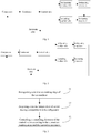
- Fig. 1 is a block diagram of a refrigeration system that can be implemented in a method for controlling refrigeration of a refrigerator according to an embodiment of the present disclosure.
- the refrigeration system at least includes a compressor, a condenser, a control valve, a refrigerating capillary tube, an ice-making capillary tube, a refrigerating evaporator, an ice-making evaporator and an air return pipe.
- the compressor is connected to the condenser, the condenser is connected to the control valve, the control valve is respectively connected to the refrigerating capillary tube and the ice-making capillary tube, the refrigerating capillary tube is connected to the refrigerating evaporator, the ice-making capillary tube is connected to the ice-making evaporator, the ice-making evaporator is connected to the compressor through the air return pipe, and the refrigerating evaporator is connected to the ice-making evaporator.
- the refrigerating evaporator is configured to refrigerate the refrigerating compartment in the refrigerator, and the ice-making evaporator is configured to make ice in the ice machine, that is, for making ice in an ice-making compartment.
- the control valve is configured to control switching on or switching off a connecting direction to the refrigerating capillary tube and the ice-making capillary tube.
- Fig. 2 is a block diagram of a refrigeration system that can be implemented in a method for controlling refrigeration of a refrigerator according to an embodiment of the present disclosure.
- the refrigeration system in Fig. 2 differs from that in Fig. 1 in that the refrigerating evaporator in this refrigeration system is not connected to the ice-making evaporator but is connected to the compressor through the air return pipe.
- the ice machine in the embodiments of the present disclosure can be located but not limited to, in a refrigerating compartment or a freezing compartment of the refrigerator, and the specific location can be determined according to actual conditions.
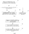
- Fig. 3 is a schematic flow chart of a method for controlling refrigeration of a refrigerator according to an embodiment of the present disclosure. As shown in Fig. 3 , the method for controlling refrigeration of a refrigerator in this embodiment includes the following steps.
- the ice-making stage of the ice machine includes two stages, i.e., a heating-deicing stage and a first ice-making stage.
- a heating wire in the ice machine works to melt part of ice cubes, thereby causing the ice cubes to fall off.
- the ice-making evaporator works to decrease the temperature of the ice-making compartment, so that the liquid solidifies into a solid.
- the ice-making stage of the ice machine may be referred to as an ice-making mode
- the non-ice-making stage of the ice machine may be referred to as a non-ice-making mode to facilitate describing and distinguishing the ice-making stage and the non-ice-making stage.
- a user's interactive interface or working mode selection button may be provided on the refrigerator, that the ice machine is currently operating in an ice-making mode can be determined by user according to the user's interactive interface or working mode selection button on the refrigerator. If the user selects the ice-making mode through the user's interactive interface, it is determined that the ice machine is currently operating in an ice-making mode.
- the working mode can be selected through voice or remote control. When the ice-making mode is selected through voice or remote control, it can be determined that the ice machine is currently operating in an ice-making mode.
- the current ice-making stage in the ice-making mode can be determined according to the current operating power of the refrigerator.
- the operating power during the heating-deicing stage (hereinafter referred to as the "first power") is greater than the refrigerating power of the ice-making compartment alone in the refrigerator, but it is less than the refrigerating power of both the ice-making compartment and the refrigerating compartment in the refrigerator (hereinafter referred to as the "first power").
- the operating power of the refrigerator (hereinafter referred to as the "third power” for convenience of description) would be greater than the second power due to the large power of heating wire in the ice machine. As shown in Fig.
- line 1 shows the change of temperature in the refrigerating compartment
- line 2 shows the change of temperature in the ice-making compartment
- line 3 shows the change of operating power of the refrigerator.
- the refrigerating compartment does not perform refrigeration but the ice-making mode is in the heating-deicing stage
- the refrigerating compartment performs refrigeration and the ice-making mode is in the heating-deicing stage
- the refrigerating compartment continues refrigeration but the ice-making mode turns to an ice-making stage
- the refrigerating compartment stops refrigeration and the ice-making mode keeps in the ice-making stage until the ice-making stage ends.
- the operating power P during the heating-deicing stage is within the range of the first power PI to the second power P2.
- whether the ice-making mode is in the heating-deicing stage can be determined according to the operating power of the refrigerator. If the ice-making mode is not in the heating-deicing stage, it is in a first ice-making stage.
- a current temperature of the heating wire in the ice machine can be detected, thereby determining the current temperature of the heating wire. If the current temperature of the heating wire is higher than the preset temperature, it indicates that the ice machine is currently in the heating-deicing stage of the ice-making mode.
- a temperature sensor may be provided in the ice-making compartment in the refrigerator, to detect the current temperature of the ice-making compartment.
- the connecting direction of the control valve can be controlled to determine whether the refrigerating compartment is to be refrigerated.
- the refrigeration cycle of the refrigerating compartment matches the ice-making cycle of the ice-making compartment, thus reducing the influence of the refrigeration in the refrigerating compartment on the ice-making in the ice machine, improving the ice-making efficiency and ice-making amount, shortening the ice-making cycle, and reducing the energy consumption of the refrigerator.
- the refrigeration cycle of the refrigerating compartment is same as the refrigeration cycle of the ice-making compartment.
- the ice-making efficiency of the ice machine is the highest, the ice-making amount is the highest and the energy consumption of the refrigerator is the lowest.
- the refrigerating compartment is in a refrigeration stage and the ice-making compartment is in a heating-deicing stage; during the time period from t1 to t2, the refrigerating compartment ends refrigerating, the ice-making compartment starts into the first ice-making stage, and making ice begins.
- the refrigeration cycle of the refrigerating compartment matches the ice-making cycle of the ice-making compartment, thereby forming the cycles as shown in Fig.
- the present disclosure in embodiments proposes a method for controlling refrigeration of a refrigerator.
- the method controls the connecting direction of the control valve in the refrigeration system of the refrigerator according to the current ice-making stage of the ice machine and the current temperature of the ice-making compartment.
- the refrigeration period of the refrigerating compartment is controlled and the starting refrigeration time of the refrigerating compartment is delayed to be within a heating-deicing stage of ice-making mode of the ice-making compartment, such that the refrigeration cycle of the refrigerating compartment matches the ice-making cycle of the ice-making compartment, thus improving the ice-making efficiency of the ice machine and the ice-making amount, shortening the ice-making cycle, and reducing the energy consumption of the refrigerator.
- Fig. 6 is a schematic flow chart of a process for controlling a starting refrigeration time of the refrigerating compartment in a method for controlling refrigeration of a refrigerator according to an embodiment of the present disclosure. As shown in Fig. 6 , the method includes the following steps.
- the refrigerator is in the heating-deicing stage can be determined according to the current operating power of the refrigerator. Referring to the description in step S1, if the current operating power of the refrigerator is between the first power and the second power, it indicates that the current ice-making stage is a heating-deicing stage.
- a first preset temperature threshold is preset in the refrigerator, and whether the refrigeration in the refrigerating compartment is initiated can be determined according to the temperature in the ice-making compartment and the first preset temperature threshold.
- the first preset temperature threshold is set, and only when the temperature in the ice-making compartment is greater than the first preset temperature threshold, the refrigeration in the refrigerating compartment can be initiated, thereby capable of delaying the starting refrigeration time of the refrigerating compartment, such that the refrigeration cycle of the refrigerating compartment matches the ice-making cycle of the ice-making compartment.
- the current temperature of the refrigerating compartment of the refrigerator is acquired and it can be compared with the first preset temperature threshold. Further, the magnitude relationship between the current temperature of the refrigerating compartment of the refrigerator and the first preset temperature threshold can be determined. If the current temperature is greater than the first preset temperature threshold, step S63 is executed; otherwise, step S64 is executed.
- the refrigeration of the refrigerating compartment is performed, that is, controlling the control valve to switch on the connecting direction to the refrigerating capillary tube. It should be understood that the control valve switches off the connecting direction to the ice-making capillary tube at this time.
- the control valve switches off, that is, the refrigeration system stops refrigerating, thereby delaying the starting refrigeration time of the refrigerating compartment.
- Fig. 7 is a schematic flow chart of a process for improving ice-making efficiency in a method for controlling refrigeration of a refrigerator according to an embodiment of the present disclosure. As shown in Fig. 7 , the method includes the following steps.
- heating-deicing stage ends can be detected.
- the heating-deicing stage ends it indicates that the current ice-making stage is in the first ice-making stage.
- a second preset temperature threshold is preset in the refrigerator. Whether the refrigeration in the refrigerating compartment ends can be determined according to the temperature in the ice-making compartment and the second preset temperature threshold. The setting of the second preset temperature threshold prevents the refrigerating compartment and the ice-making compartment from simultaneously refrigerating for a long time, thus not only reducing energy consumption and improving ice-making efficiency, but also meeting the refrigeration requirements of the refrigerating compartment.
- the refrigeration of the refrigerating compartment is ended in advance to ensure ice-making efficiency; and if the target temperature set in the refrigerating compartment is greater than or equal to the second preset temperature threshold, the refrigeration of the refrigerating compartment can be ended when the target temperature is reached.
- the current temperature of the refrigerating compartment of the refrigerator is acquired and it can be compared with the second preset temperature threshold. Further, the magnitude relationship between the current temperature of the refrigerating compartment of the refrigerator and the second preset temperature threshold can be determined. If the current temperature is greater than the second preset temperature threshold, step S73 is executed; otherwise, step S74 is executed.
- the control valve is controlled to switch on the connecting direction to both the refrigerating capillary tube and the ice-making capillary tube, thus performing the refrigeration in both the ice-making compartment and the refrigerating compartment.
- the control valve is controlled to switch off the connecting direction to the refrigerating capillary tube, thus ending the refrigeration in the refrigerating compartment.
- the method needs to acquire a refrigeration request instruction issued by either the refrigerating compartment or the ice-making compartment before controlling a connecting direction of the control valve, and select the connecting direction to be switched on by the control valve according to the corresponding refrigeration request instruction.
- the connecting direction of the control valve can be controlled according to the following steps. As shown in Fig. 8 , the method includes steps.
- step S 1 if the ice machine is not in the ice-making mode, it is determined that the ice machine is currently operating in a non-ice-making mode.
- the refrigeration request instruction issued by respective compartment can be detected in real time or at intervals.
- the connecting direction of the control valve is controlled according to the refrigeration request instruction issued by corresponding compartments. For example, if the ice-making compartment and the refrigerating compartment both issue a refrigeration request instruction, the control valve would switch on the connecting direction to both the refrigerating capillary tube and the ice-making capillary tube. If the ice-making compartment issues a refrigeration request instruction but the refrigerating compartment does not issue a refrigeration request instruction, the control valve would switch on the connecting direction to the ice-making capillary tube but would switch off the connecting direction to the refrigerating capillary tube.
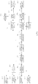
- Fig. 9 is a flow chart of a process for controlling a method for controlling refrigeration of a refrigerator according to an embodiment of the present disclosure. As shown in Fig. 9 , the process for controlling a method for controlling refrigeration of a refrigerator according to an embodiment of the present disclosure includes the following steps.
- step S92 is executed. If no, a step S93 is executed.
- step S921 is executed. If no, a step S922 is executed.
- step S8211 is executed. If no, a step S9212 is executed.
- step S9213 is executed. If no, a step S9212 is executed.
- the control valve switches on the connecting direction to the ice-making capillary tube.
- the control valve switches on the connecting direction to both the refrigerating capillary tube and the ice-making capillary tube.
- step S9221 is executed. If no, a step S9222 is executed.
- step S9222 is executed. If no, a step S9223 is executed.
- the control valve switches on the connecting direction to the refrigerating capillary tube.
- step S931 is executed. If no, a step S932 is executed.
- step S9311 is executed. If no, a step S9312 is executed.
- the control valve switches on the connecting direction to both the refrigerating capillary tube and the ice-making capillary tube.
- the control valve switches on the connecting direction to the ice-making capillary tube.
- step S9321 is executed. If no, a step S9322 is executed.
- control valve switches on the connecting direction to the refrigerating capillary tube.
- the refrigeration system of the refrigerator is controlled, such that the refrigeration cycle of the refrigerating compartment matches the ice-making cycle of the ice-making compartment, referring to Fig. 4 showing the schematic diagram of the refrigeration cycle of refrigerating compartment and the ice-making cycle of ice-making compartment. Therefore, the ice-making in the ice machine is less influenced by the refrigeration in the refrigerating compartment, improving the ice-making efficiency and ice-making amount, shortening the ice-making cycle, and reducing the energy consumption of the refrigerator.
- a refrigeration system of the refrigerator includes:
- Fig. 10 is a block diagram showing the structure of a device for controlling refrigeration of a refrigerator according to an embodiment of the present disclosure. As shown in Figure 10 , the device includes:
- controlling module 1003 is further configured to:
- controlling module 1003 is further configured to:
- controlling module 1003 is further configured to:
- controlling module 1003 is further configured to:
- controlling module 1003 is further configured to:
- controlling module 1003 is further configured to: acquire a refrigeration request instruction issued by either the refrigerating compartment or the ice-making compartment.
- controlling module 1003 is further configured to: detect and determine that the ice machine is currently operating in an ice-making mode before recognizing a current ice-making stage of the ice machine.
- controlling module 1003 is further configured to:
- the foregoing device is configured to execute the method described in the foregoing embodiments.
- the corresponding program module in the device has implementation principles and technical effects which are similar to those described in the foregoing method.
- the working process of the device may take reference to the process of the corresponding method as above, which will not be repeated herein.
- the controlling module in the device controls a connecting direction of the control valve in the refrigeration system of the refrigerator according to the current ice-making stage of the ice machine recognized by the recognizing module and the current temperature of the ice-making compartment acquired by the acquiring module.
- the connecting direction of the control valve is controlled to determine the time of performing refrigeration and the time of ending refrigeration for corresponding compartments, thereby controlling the refrigeration period of the refrigerating compartment and delaying the starting refrigeration time of the refrigerating compartment to be within a heating-deicing stage of ice-making mode of the ice-making compartment, such that the refrigeration cycle of the refrigerating compartment matches the ice-making cycle of the ice-making compartment, thus improving the ice-making efficiency of the ice machine and ice-making amount, shortening the ice-making cycle, and reducing the energy consumption of the refrigerator.
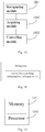
- Fig. 11 is a block diagram showing the structure of a refrigerator according to an embodiment of the present disclosure.
- the refrigerator includes the device for controlling refrigeration of a refrigerator 100.
- Fig. 12 is a block diagram showing the structure of an electronic device according to an embodiment of the present disclosure.
- the electronic device includes a memory 1201 and a processor 1202; wherein the processor 1202 runs a program corresponding to an executable program code by reading the executable program code stored in the memory 1201, to be configured to implement each step in the method described above.
- the present disclosure still further proposes a non-transitory computer-readable storage medium having stored therein a computer program that, when executed by a processor, causes the processor to implement each step in the method described above.
- first and second are only used for descriptive purposes and cannot be understood as indicating or implying relative importance or implicitly indicating the number of indicated technical features. Therefore, the features defined with “first” and “second” may explicitly or implicitly include at least one of the features.
- the “plurality” means two or more than two, unless otherwise specifically defined.
- the terms “disposed”, “arranged”, “connected”, “fixed” and the like should be understood broadly and may be either a fixed connection or a detachable connection, or an integration; may be a mechanical connection, or an electrical connection; may be directly connected, or connected via an intermediate medium; and may be the internal communication of two elements or the interaction of two elements, unless otherwise explicitly stated and defined.
- the specific meanings of the above terms in the present disclosure can be understood according to specific situations.
- a first feature "on” or “under” a second feature may refer to a direct contact of the first feature with the second feature or an indirect contact of the first feature and the second feature via an intermediate medium, unless otherwise explicitly stated and defined.
- a first feature "above” a second feature may mean the first feature is right above or obliquely above the second feature, or merely that the first feature is located at a level higher than the second feature.
- a first feature “below” a second feature may mean the first feature is just below or obliquely below the second feature, or merely that the first feature is located at a level lower than the second feature.
Landscapes
- Engineering & Computer Science (AREA)
- Physics & Mathematics (AREA)
- Mechanical Engineering (AREA)
- Thermal Sciences (AREA)
- General Engineering & Computer Science (AREA)
- Chemical & Material Sciences (AREA)
- Combustion & Propulsion (AREA)
- Production, Working, Storing, Or Distribution Of Ice (AREA)
Abstract
Description
- This application claims a priority to Chinese Patent Application in application name of refrigerator and method and device for controlling refrigeration thereof filed on January 09, 2019 of HEFEI HUALING CO., LTD., HEFEI MIDEA REFRIGERATOR CO., LTD. and MIDEA GROUP CO., LTD.
- This application belongs to the technical field of household appliances, in particular to a refrigerator and a method and device for controlling refrigeration of a refrigerator.
- In the related art, a refrigerator with an ice machine has no requirement for a refrigeration period of a refrigerating compartment and an ice-making period of the ice machine. That is, when the ice machine is in an ice-making state, the refrigerating compartment can request and perform refrigeration at any time, thus often leading to low ice-making efficiency of the ice machine, and high energy consumption of the refrigerator.
- This application aims to solve one of the technical problems in the related technology at least to a certain extent.
- For this, the present disclosure in embodiments proposes a method for controlling refrigeration of a refrigerator. The method for controlling refrigeration of a refrigerator is capable of controlling the refrigeration period of the refrigerating compartment, so that the refrigeration cycle of the refrigerating compartment matches the ice-making cycle of the ice machine, thus improving the ice-making efficiency of the ice machine and reducing the energy consumption of the refrigerator.
- This present disclosure in embodiments also proposes a device for controlling refrigeration of a refrigerator and a refrigerator.
- To solve the above problem, a first aspect of the present disclosure in embodiments proposes a method for controlling refrigeration of a refrigerator, wherein a refrigeration system of the refrigerator comprises:
- a refrigerating evaporator for refrigerating a refrigerating compartment,
- an ice-making evaporator for making ice in an ice machine,
- a refrigerating capillary tube and an ice-making capillary tube adjacent to the refrigerating evaporator and the ice-making evaporator, and
- a control valve for controlling the refrigerating capillary tube and the ice-making capillary tube;
- the method comprises:
- recognizing a current ice-making stage of the ice machine;
- acquiring a current temperature of an ice-making compartment in the refrigerator; and
- controlling a connecting direction of the control valve according to the current ice-making stage and the current temperature.
- According to the method for controlling refrigeration of a refrigerator in embodiments of the present disclosure, the connecting direction of the control valve is controlled to determine the time of performing refrigeration and the time of ending refrigeration for corresponding compartments, thereby controlling the refrigeration period of the refrigerating compartment and delaying the starting refrigeration time of the refrigerating compartment to be within a heating-deicing stage of ice-making mode of the ice-making compartment, such that the refrigeration cycle of the refrigerating compartment matches the ice-making cycle of the ice-making compartment, thus improving the ice-making efficiency of the ice machine and reducing the energy consumption of the refrigerator.
- In embodiments of the present disclosure, controlling a connecting direction of the control valve according to the current ice-making stage and the current temperature comprises:
- detecting and determining that the current ice-making stage is a heating-deicing stage;
- detecting and determining that the current temperature is greater than a first preset temperature threshold; and
- controlling the control valve to switch on the connecting direction to the refrigerating capillary tube.
- In embodiments of the present disclosure, the method further comprises:
- detecting and determining that the current temperature is less than or equal to the first preset temperature threshold; and
- controlling the control valve to switch off.
- In embodiments of the present disclosure, detecting and determining that the current ice-making stage is a heating-deicing stage comprises:
- acquiring a current operating power of the refrigerator;
- detecting and determining that the current operating power is within a preset range; and
- determining that the current ice-making stage is the heating-deicing stage.
- In embodiments of the present disclosure, the method further comprises:
- detecting and determining that the current ice-making stage is a first ice-making stage;
- detecting and determining that the current temperature is greater than a second preset temperature threshold; and
- controlling the control valve to switch on the connecting direction to both the refrigerating capillary tube and the ice-making capillary tube.
- In embodiments of the present disclosure, the method further comprises:
- detecting and determining that the current temperature is less than or equal to the second preset temperature threshold; and
- controlling the control valve to switch off the connecting direction to the refrigerating capillary tube.
- In embodiments of the present disclosure, the method further comprises:
- acquiring a refrigeration request instruction issued by either the refrigerating compartment or the ice-making compartment,
- before controlling a connecting direction of the control valve according to the current ice-making stage and the current temperature.
- In embodiments of the present disclosure, the method further comprises:
- detecting and determining that the ice machine is currently operating in an ice-making mode,
- before recognizing a current ice-making stage of the ice machine.
- In embodiments of the present disclosure, the method further comprises:
- detecting and determining that the ice machine is currently operating in a non-ice making mode;
- detecting a refrigeration request instruction issued by either the refrigerating compartment or the ice-making compartment; and
- controlling the connecting direction of the control valve according to the detected refrigeration request instruction and a source of the refrigeration request instruction.
- The present disclosure in embodiments further proposes an electronic device, comprising:
- at least one memory;
- a processor;
- at least one program,
- wherein the at least one program is stored in the memory that when executed by the at least one processor, to implement a method for controlling refrigeration of a refrigerator as described in the embodiments of the first aspect of the present disclosure.
- The present disclosure in embodiments still further proposes a non-transitory computer-readable storage medium having stored therein a computer program that, when executed by a processor, causes the processor to perform a method for controlling refrigeration of a refrigerator as described in the embodiments of the first aspect of the present disclosure.
- To solve the above problem, a second aspect of the present disclosure in embodiments proposes a device for controlling refrigeration of a refrigerator, wherein a refrigeration system of the refrigerator comprises:
- a refrigerating evaporator for refrigerating a refrigerating compartment,
- an ice-making evaporator for making ice in an ice machine,
- a refrigerating capillary tube and an ice-making capillary tube adjacent to the refrigerating evaporator and the ice-making evaporator, and
- a control valve for controlling the refrigerating capillary tube and the ice-making capillary tube;
- the device comprises:
- a recognizing module, configured to recognize a current ice-making stage of the ice machine;
- an acquiring module, configured to acquire a current temperature of the ice-making compartment in the refrigerator; and
- a controlling module, configured to control a connecting direction of the control valve according to the current ice-making stage and the current temperature.
- According to the device for controlling refrigeration of a refrigerator in embodiments of the present disclosure, the connecting direction of the control valve is controlled to determine the time of performing refrigeration and the time of ending refrigeration for corresponding compartments, thereby controlling the refrigeration period of the refrigerating compartment and delaying the starting refrigeration time of the refrigerating compartment to be within a heating-deicing stage of ice-making mode of the ice-making compartment, such that the refrigeration cycle of the refrigerating compartment matches the ice-making cycle of the ice-making compartment, thus improving the ice-making efficiency of the ice machine and reducing the energy consumption of the refrigerator.
- In embodiments of the present disclosure, the controlling module is further configured to:
- detect and determine that the current ice-making stage is a heating-deicing stage;
- detect and determine that the current temperature is greater than a first preset temperature threshold; and
- control the control valve to switch on the connecting direction to the refrigerating capillary tube.
- In embodiments of the present disclosure, the controlling module is further configured to:
- detect and determine that the current temperature is less than or equal to the first preset temperature threshold; and
- control the control valve to switch off.
- In embodiments of the present disclosure, the controlling module is further configured to:
- acquire a current operating power of the refrigerator;
- detect and determine that the current operating power is within a preset range; and determine that the current ice-making stage is the heating-deicing stage.
- In embodiments of the present disclosure, the controlling module is further configured to:
- detect and determine that the current ice-making stage is a first ice-making stage;
- detect and determine that the current temperature is greater than a second preset temperature threshold; and
- control the control valve to switch on the connecting direction to both the refrigerating capillary tube and the ice-making capillary tube.
- In embodiments of the present disclosure, the controlling module is further configured to:
- detect and determine that the current temperature is less than or equal to the second preset temperature threshold; and
- control the control valve to switch off the connecting direction to the refrigerating capillary tube.
- In embodiments of the present disclosure, the controlling module is further configured to:
acquire a refrigeration request instruction issued by either the refrigerating compartment or the ice-making compartment. - In embodiments of the present disclosure, the controlling module is further configured to:
detect and determine that the ice machine is currently operating in an ice-making mode before recognizing a current ice-making stage of the ice machine. - In embodiments of the present disclosure, the controlling module is further configured to:
- detect and determine that the ice machine is currently operating in a non-ice making mode;
- detect a refrigeration request instruction issued by either the refrigerating compartment or the ice-making compartment; and
- control the connecting direction of the control valve according to the detected refrigeration request instruction and a source of the refrigeration request instruction.
- A third aspect of the present disclosure in embodiments proposes a refrigerator, comprising the device for controlling refrigeration of a refrigerator, based on the device for controlling refrigeration of a refrigerator as described in embodiments of the above aspect. According to the device for controlling refrigeration of a refrigerator as described in embodiments of the above aspect, it is possible to implement the controlling of refrigeration period of the refrigerating compartment, such that the refrigeration cycle of the refrigerating compartment matches the ice-making cycle of the ice machine, thus improving the ice-making efficiency of the ice machine and reducing the energy consumption of the refrigerator.
-
-
Fig. 1 is a block diagram of a refrigeration system that can be implemented in a method for controlling refrigeration of a refrigerator according to an embodiment of the present disclosure; -
Fig. 2 is a block diagram of a refrigeration system that can be implemented in a method for controlling refrigeration of a refrigerator according to an embodiment of the present disclosure; -
Fig. 3 is a schematic flow chart of a method for controlling refrigeration of a refrigerator according to an embodiment of the present disclosure; -
Fig. 4 is a schematic diagram showing a refrigeration cycle of a refrigerating compartment and an ice-making cycle of an ice-making compartment in a method for controlling refrigeration of a refrigerator according to an embodiment of the present disclosure; -
Fig. 5 is a schematic diagram of comparison of a refrigeration cycle of a refrigerating compartment and an ice-making cycle of an ice-making compartment in a method for controlling refrigeration of a refrigerator according to an embodiment of the present disclosure; -
Fig. 6 is a schematic flow chart of a process for controlling a starting refrigeration time of a refrigerating compartment in a method for controlling refrigeration of a refrigerator according to an embodiment of the present disclosure; -
Fig. 7 is a schematic flow chart of a process for improving ice-making efficiency in a method for controlling refrigeration of a refrigerator according to an embodiment of the present disclosure; -
Fig. 8 is a schematic flow chart of a method for controlling refrigeration of a refrigerator according to an embodiment of the present disclosure; -
Fig. 9 is a flow chart of a process for controlling a method for controlling refrigeration of a refrigerator according to an embodiment of the present disclosure; -
Fig. 10 is a block diagram showing the structure of a device for controlling refrigeration of a refrigerator according to an embodiment of the present disclosure; -
Fig. 11 is a block diagram showing the structure of a refrigerator according to an embodiment of the present disclosure; -
Fig. 12 is a block diagram showing the structure of an electronic device according to an embodiment of the present disclosure. - The embodiments of the present disclosure are described in detail below. Examples of the embodiments are shown in the accompanying drawings, in which the same or similar reference numerals indicate the same or similar elements or elements with the same or similar functions. The embodiments described below with reference to the drawings are exemplary and are intended to explain the present disclosure, which should not be understood as a limitation to the present disclosure.
- A refrigerator and a method and device for controlling refrigeration of a refrigerator according to embodiments of the present disclosure are described below with reference to the drawings.
-
Fig. 1 is a block diagram of a refrigeration system that can be implemented in a method for controlling refrigeration of a refrigerator according to an embodiment of the present disclosure. As shown inFig. 1 , the refrigeration system at least includes a compressor, a condenser, a control valve, a refrigerating capillary tube, an ice-making capillary tube, a refrigerating evaporator, an ice-making evaporator and an air return pipe. Among them, the compressor is connected to the condenser, the condenser is connected to the control valve, the control valve is respectively connected to the refrigerating capillary tube and the ice-making capillary tube, the refrigerating capillary tube is connected to the refrigerating evaporator, the ice-making capillary tube is connected to the ice-making evaporator, the ice-making evaporator is connected to the compressor through the air return pipe, and the refrigerating evaporator is connected to the ice-making evaporator. Among them, the refrigerating evaporator is configured to refrigerate the refrigerating compartment in the refrigerator, and the ice-making evaporator is configured to make ice in the ice machine, that is, for making ice in an ice-making compartment. The control valve is configured to control switching on or switching off a connecting direction to the refrigerating capillary tube and the ice-making capillary tube. -
Fig. 2 is a block diagram of a refrigeration system that can be implemented in a method for controlling refrigeration of a refrigerator according to an embodiment of the present disclosure. As shown inFig. 2 , the refrigeration system inFig. 2 differs from that inFig. 1 in that the refrigerating evaporator in this refrigeration system is not connected to the ice-making evaporator but is connected to the compressor through the air return pipe. - It should be noted that the ice machine in the embodiments of the present disclosure can be located but not limited to, in a refrigerating compartment or a freezing compartment of the refrigerator, and the specific location can be determined according to actual conditions.
-
Fig. 3 is a schematic flow chart of a method for controlling refrigeration of a refrigerator according to an embodiment of the present disclosure. As shown inFig. 3 , the method for controlling refrigeration of a refrigerator in this embodiment includes the following steps. - It should be noted that, in this embodiment, the ice-making stage of the ice machine includes two stages, i.e., a heating-deicing stage and a first ice-making stage. Among them, during the heating-deicing stage, a heating wire in the ice machine works to melt part of ice cubes, thereby causing the ice cubes to fall off. During the first ice-making stage, the ice-making evaporator works to decrease the temperature of the ice-making compartment, so that the liquid solidifies into a solid. It should be understood that the ice-making stage of the ice machine may be referred to as an ice-making mode, and the non-ice-making stage of the ice machine may be referred to as a non-ice-making mode to facilitate describing and distinguishing the ice-making stage and the non-ice-making stage. Optionally, it is possible to detect and determine that the ice machine is currently operating in an ice-making mode, before recognizing a current ice-making stage of the ice machine. Specifically, when detecting if the ice machine is operating in an ice-making mode, for example, a user's interactive interface or working mode selection button may be provided on the refrigerator, that the ice machine is currently operating in an ice-making mode can be determined by user according to the user's interactive interface or working mode selection button on the refrigerator. If the user selects the ice-making mode through the user's interactive interface, it is determined that the ice machine is currently operating in an ice-making mode. Optionally, the working mode can be selected through voice or remote control. When the ice-making mode is selected through voice or remote control, it can be determined that the ice machine is currently operating in an ice-making mode.
- During the heating-deicing stage in the ice-making mode, a heating wire in the ice machine need to work to increase the temperature, to cause the solidified ice cubes to fall off. Thus, the current operating power of the refrigerator would be greater than the normal operating power of the refrigerator under the action of heating wire working. Thereby, in embodiments of the present disclosure, the current ice-making stage in the ice-making mode can be determined according to the current operating power of the refrigerator.
- In the actual working process of the refrigerator, the operating power during the heating-deicing stage (hereinafter referred to as the "first power") is greater than the refrigerating power of the ice-making compartment alone in the refrigerator, but it is less than the refrigerating power of both the ice-making compartment and the refrigerating compartment in the refrigerator (hereinafter referred to as the "first power"). Thus, during the heating-deicing stage, when the refrigerator simultaneously performs the refrigeration of refrigerating compartment, the operating power of the refrigerator (hereinafter referred to as the "third power" for convenience of description) would be greater than the second power due to the large power of heating wire in the ice machine. As shown in
Fig. 4 ,line 1 shows the change of temperature in the refrigerating compartment,line 2 shows the change of temperature in the ice-making compartment, andline 3 shows the change of operating power of the refrigerator. Among them, in the time period from 0 to t1, the refrigerating compartment does not perform refrigeration but the ice-making mode is in the heating-deicing stage; in the time period from t1 to t2, the refrigerating compartment performs refrigeration and the ice-making mode is in the heating-deicing stage; in the time period from t2 to t3, the refrigerating compartment continues refrigeration but the ice-making mode turns to an ice-making stage; and in the time period from t3 to t4, the refrigerating compartment stops refrigeration and the ice-making mode keeps in the ice-making stage until the ice-making stage ends. In the entire ice-making mode, the operating power P during the heating-deicing stage is within the range of the first power PI to the second power P2. Thus, whether the ice-making mode is in the heating-deicing stage can be determined according to the operating power of the refrigerator. If the ice-making mode is not in the heating-deicing stage, it is in a first ice-making stage. - Optionally, after the ice machine is determined to be operated in the ice-making mode, a current temperature of the heating wire in the ice machine can be detected, thereby determining the current temperature of the heating wire. If the current temperature of the heating wire is higher than the preset temperature, it indicates that the ice machine is currently in the heating-deicing stage of the ice-making mode.
- Specifically, a temperature sensor may be provided in the ice-making compartment in the refrigerator, to detect the current temperature of the ice-making compartment.
- According to the current ice-making stage of the ice-making mode and the current temperature in the ice-making compartment acquired, the connecting direction of the control valve can be controlled to determine whether the refrigerating compartment is to be refrigerated. Through controlling the refrigeration period of the refrigerating compartment, the refrigeration cycle of the refrigerating compartment matches the ice-making cycle of the ice-making compartment, thus reducing the influence of the refrigeration in the refrigerating compartment on the ice-making in the ice machine, improving the ice-making efficiency and ice-making amount, shortening the ice-making cycle, and reducing the energy consumption of the refrigerator.
- It should be noted that, referring to
Fig. 5 , in an ideal state, as shown inFig. 5a , the refrigeration cycle of the refrigerating compartment is same as the refrigeration cycle of the ice-making compartment. At the time, the ice-making efficiency of the ice machine is the highest, the ice-making amount is the highest and the energy consumption of the refrigerator is the lowest. Among them, during the time period from 0 to t1, the refrigerating compartment is in a refrigeration stage and the ice-making compartment is in a heating-deicing stage; during the time period from t1 to t2, the refrigerating compartment ends refrigerating, the ice-making compartment starts into the first ice-making stage, and making ice begins. However, in a practical application, since the refrigeration cycle of the refrigerating compartment is often shorter than the ice-making cycle of the ice-making compartment, the situation shown inFig. 5b often occurs during the operation of the refrigerator, thereby generally resulting in the refrigerating compartment being in a refrigeration stage and the ice-making compartment being in a first ice-making stage. At the time, due to the amount of refrigerant splitting, the temperature of the ice-making evaporator rises, despite still lower than the preset temperature, resulting in slow down of the decrease of temperature of the ice-making compartment, decreasing the ice-making rate, increasing the ice-making cycle, reducing the ice-making amount and increasing the energy consumption. In addition, even when the starting refrigeration time of the refrigerating compartment keeps path with the heating-deicing time of the ice-making compartment, the situation shown inFig. 5c occurs, resulting in that the ice-making compartment is still in the late stage of the heating-deicing stage when the refrigerating compartment begins in a refrigeration stage again. Meanwhile, due to the amount of refrigerant splitting, the temperature of the ice-making evaporator rises, despite still lower than the preset temperature, which would slow down the decrease of temperature of the ice-making compartment, decrease the ice-making rate, increase the ice-making cycle, reduce the ice-making amount, and increase the energy consumption. However, in the embodiments of the present disclosure, through controlling the refrigeration period of the refrigerating compartment and delaying the starting refrigeration time of the refrigerating compartment to be within a heating-deicing stage of ice-making mode of the ice-making compartment, the refrigeration cycle of the refrigerating compartment matches the ice-making cycle of the ice-making compartment, thereby forming the cycles as shown inFig. 5d , thus greatly reducing the time period when both the refrigerating compartment and the ice-making compartment perform refrigerating, thereby reducing the influence of refrigeration in the refrigerating compartment on ice-making in the ice-making compartment, improving the ice-making efficiency and ice-making amount, shortening the ice-making cycle, and reducing the energy consumption of the refrigerator. - Above all, the present disclosure in embodiments proposes a method for controlling refrigeration of a refrigerator. The method controls the connecting direction of the control valve in the refrigeration system of the refrigerator according to the current ice-making stage of the ice machine and the current temperature of the ice-making compartment. Through controlling the connecting direction of the control valve to determine the time of performing refrigeration and the time of ending refrigeration for corresponding compartments, the refrigeration period of the refrigerating compartment is controlled and the starting refrigeration time of the refrigerating compartment is delayed to be within a heating-deicing stage of ice-making mode of the ice-making compartment, such that the refrigeration cycle of the refrigerating compartment matches the ice-making cycle of the ice-making compartment, thus improving the ice-making efficiency of the ice machine and the ice-making amount, shortening the ice-making cycle, and reducing the energy consumption of the refrigerator.
- In some embodiments, the time of performing refrigeration in the refrigerating compartment can be determined according to the temperature in the ice-making compartment.
Fig. 6 is a schematic flow chart of a process for controlling a starting refrigeration time of the refrigerating compartment in a method for controlling refrigeration of a refrigerator according to an embodiment of the present disclosure. As shown inFig. 6 , the method includes the following steps. - Specifically, if the refrigerator is in the heating-deicing stage can be determined according to the current operating power of the refrigerator. Referring to the description in step S1, if the current operating power of the refrigerator is between the first power and the second power, it indicates that the current ice-making stage is a heating-deicing stage.
- It should be noted that a first preset temperature threshold is preset in the refrigerator, and whether the refrigeration in the refrigerating compartment is initiated can be determined according to the temperature in the ice-making compartment and the first preset temperature threshold. In embodiments of the present disclosure, the first preset temperature threshold is set, and only when the temperature in the ice-making compartment is greater than the first preset temperature threshold, the refrigeration in the refrigerating compartment can be initiated, thereby capable of delaying the starting refrigeration time of the refrigerating compartment, such that the refrigeration cycle of the refrigerating compartment matches the ice-making cycle of the ice-making compartment.
- Specifically, the current temperature of the refrigerating compartment of the refrigerator is acquired and it can be compared with the first preset temperature threshold. Further, the magnitude relationship between the current temperature of the refrigerating compartment of the refrigerator and the first preset temperature threshold can be determined. If the current temperature is greater than the first preset temperature threshold, step S63 is executed; otherwise, step S64 is executed.
- Specifically, when the current temperature is greater than the first preset temperature threshold, the refrigeration of the refrigerating compartment is performed, that is, controlling the control valve to switch on the connecting direction to the refrigerating capillary tube. It should be understood that the control valve switches off the connecting direction to the ice-making capillary tube at this time.
- Specifically, if the current temperature is less than or equal to the first preset temperature threshold, the control valve switches off, that is, the refrigeration system stops refrigerating, thereby delaying the starting refrigeration time of the refrigerating compartment.
- In some embodiments, considering that the simultaneous refrigeration of the refrigerating compartment and the refrigerating compartment for a long time would reduce the ice-making efficiency and increase the energy consumption, the refrigeration ending period of the refrigerating compartment can also be controlled to avoid occurrence of the above situation. Specifically, referring to
Fig. 7, Fig. 7 is a schematic flow chart of a process for improving ice-making efficiency in a method for controlling refrigeration of a refrigerator according to an embodiment of the present disclosure. As shown inFig. 7 , the method includes the following steps. - Specifically, whether the heating-deicing stage ends can be detected. When the heating-deicing stage ends, it indicates that the current ice-making stage is in the first ice-making stage.
- It should be noted that a second preset temperature threshold is preset in the refrigerator. Whether the refrigeration in the refrigerating compartment ends can be determined according to the temperature in the ice-making compartment and the second preset temperature threshold. The setting of the second preset temperature threshold prevents the refrigerating compartment and the ice-making compartment from simultaneously refrigerating for a long time, thus not only reducing energy consumption and improving ice-making efficiency, but also meeting the refrigeration requirements of the refrigerating compartment. For example, if the target temperature set in the refrigerating compartment is lower than the second preset temperature threshold, the refrigeration of the refrigerating compartment is ended in advance to ensure ice-making efficiency; and if the target temperature set in the refrigerating compartment is greater than or equal to the second preset temperature threshold, the refrigeration of the refrigerating compartment can be ended when the target temperature is reached.
- Specifically, the current temperature of the refrigerating compartment of the refrigerator is acquired and it can be compared with the second preset temperature threshold. Further, the magnitude relationship between the current temperature of the refrigerating compartment of the refrigerator and the second preset temperature threshold can be determined. If the current temperature is greater than the second preset temperature threshold, step S73 is executed; otherwise, step S74 is executed.
- Specifically, if the current temperature is greater than the second preset temperature threshold, the control valve is controlled to switch on the connecting direction to both the refrigerating capillary tube and the ice-making capillary tube, thus performing the refrigeration in both the ice-making compartment and the refrigerating compartment.
- Specifically, if the current temperature is less than or equal to the second preset temperature threshold, the control valve is controlled to switch off the connecting direction to the refrigerating capillary tube, thus ending the refrigeration in the refrigerating compartment.
- It should be understood that, in this embodiment, the method needs to acquire a refrigeration request instruction issued by either the refrigerating compartment or the ice-making compartment before controlling a connecting direction of the control valve, and select the connecting direction to be switched on by the control valve according to the corresponding refrigeration request instruction.
- In some embodiments, if the ice machine is currently operating in a non-ice-making mode, the connecting direction of the control valve can be controlled according to the following steps. As shown in
Fig. 8 , the method includes steps. - Specifically, referring to the description in
step S 1 as above, if the ice machine is not in the ice-making mode, it is determined that the ice machine is currently operating in a non-ice-making mode. - Specifically, during the operation of the refrigerator, when the internal temperature of the refrigerator changes, compartments like the refrigerating compartment, the ice-making compartment and the like are to be refrigerated from time to time. When a corresponding compartment needs to be refrigerated, the corresponding compartment will issue a refrigeration request instruction to request being refrigerated by the refrigerator. Thus, the refrigeration request instruction issued by respective compartment can be detected in real time or at intervals.
- Specifically, the connecting direction of the control valve is controlled according to the refrigeration request instruction issued by corresponding compartments. For example, if the ice-making compartment and the refrigerating compartment both issue a refrigeration request instruction, the control valve would switch on the connecting direction to both the refrigerating capillary tube and the ice-making capillary tube. If the ice-making compartment issues a refrigeration request instruction but the refrigerating compartment does not issue a refrigeration request instruction, the control valve would switch on the connecting direction to the ice-making capillary tube but would switch off the connecting direction to the refrigerating capillary tube.
-
Fig. 9 is a flow chart of a process for controlling a method for controlling refrigeration of a refrigerator according to an embodiment of the present disclosure. As shown inFig. 9 , the process for controlling a method for controlling refrigeration of a refrigerator according to an embodiment of the present disclosure includes the following steps. - If yes, a step S92 is executed. If no, a step S93 is executed.
- If yes, a step S921 is executed. If no, a step S922 is executed.
- If yes, a step S8211 is executed. If no, a step S9212 is executed.
- If yes, a step S9213 is executed. If no, a step S9212 is executed.
- S9212. The control valve switches on the connecting direction to the ice-making capillary tube.
- S9213. The control valve switches on the connecting direction to both the refrigerating capillary tube and the ice-making capillary tube.
- If yes, a step S9221 is executed. If no, a step S9222 is executed.
- If yes, a step S9222 is executed. If no, a step S9223 is executed.
- S9222. The control valve switches on the connecting direction to the refrigerating capillary tube.
- S9223. The connecting direction of the control valve remains unchanged and the refrigeration system stops refrigerating.
- If yes, a step S931 is executed. If no, a step S932 is executed.
- If yes, a step S9311 is executed. If no, a step S9312 is executed.
- 59311. The control valve switches on the connecting direction to both the refrigerating capillary tube and the ice-making capillary tube.
- S9312. The control valve switches on the connecting direction to the ice-making capillary tube.
- If yes, a step S9321 is executed. If no, a step S9322 is executed.
- S9321. The control valve switches on the connecting direction to the refrigerating capillary tube.
- S9322. The connecting direction of the control valve remains unchanged and the refrigeration system stops refrigerating.
- It should be noted that, according to the method proposed in this embodiment, the refrigeration system of the refrigerator is controlled, such that the refrigeration cycle of the refrigerating compartment matches the ice-making cycle of the ice-making compartment, referring to
Fig. 4 showing the schematic diagram of the refrigeration cycle of refrigerating compartment and the ice-making cycle of ice-making compartment. Therefore, the ice-making in the ice machine is less influenced by the refrigeration in the refrigerating compartment, improving the ice-making efficiency and ice-making amount, shortening the ice-making cycle, and reducing the energy consumption of the refrigerator. - To implement the method in the foregoing embodiments, the present disclosure still further proposes a device for controlling refrigeration of a refrigerator, in which a refrigeration system of the refrigerator includes:
- a refrigerating evaporator for refrigerating a refrigerating compartment,
- an ice-making evaporator for making ice in an ice machine,
- a refrigerating capillary tube and an ice-making capillary tube adjacent to the refrigerating evaporator and the ice-making evaporator, and
- a control valve for controlling the refrigerating capillary tube and the ice-making capillary tube.
-
Fig. 10 is a block diagram showing the structure of a device for controlling refrigeration of a refrigerator according to an embodiment of the present disclosure. As shown inFigure 10 , the device includes: - a recognizing
module 1001, configured to recognize a current ice-making stage of the ice machine; - an acquiring
module 1002, configured to acquire a current temperature of the ice-making compartment in the refrigerator; and - a
controlling module 1003, configured to control a connecting direction of the control valve according to the current ice-making stage and the current temperature. - Further, the controlling
module 1003 is further configured to: - detect and determine that the current ice-making stage is a heating-deicing stage;
- detect and determine that the current temperature is greater than a first preset temperature threshold; and
- control the control valve to switch on the connecting direction to the refrigerating capillary tube.
- Further, the controlling
module 1003 is further configured to: - detect and determine that the current temperature is less than or equal to the first preset temperature threshold; and
- control the control valve to switch off.
- Further, the controlling
module 1003 is further configured to: - acquire a current operating power of the refrigerator;
- detect and determine that the current operating power is within a preset range; and
- determine that the current ice-making stage is the heating-deicing stage.
- Further, the controlling
module 1003 is further configured to: - detect and determine that the current ice-making stage is a first ice-making stage;
- detect and determine that the current temperature is greater than a second preset temperature threshold; and
- control the control valve to switch on the connecting direction to both the refrigerating capillary tube and the ice-making capillary tube.
- Further, the controlling
module 1003 is further configured to: - detect and determine that the current temperature is less than or equal to the second preset temperature threshold; and
- control the control valve to switch off the connecting direction to the refrigerating capillary tube.
- Further, the controlling
module 1003 is further configured to:
acquire a refrigeration request instruction issued by either the refrigerating compartment or the ice-making compartment. - Further, the controlling
module 1003 is further configured to:
detect and determine that the ice machine is currently operating in an ice-making mode before recognizing a current ice-making stage of the ice machine. - Further, the controlling
module 1003 is further configured to: - detect and determine that the ice machine is currently operating in a non-ice making mode;
- detect a refrigeration request instruction issued by either the refrigerating compartment or the ice-making compartment; and
- control the connecting direction of the control valve according to the detected refrigeration request instruction and a source of the refrigeration request instruction.
- It should be understood that the foregoing device is configured to execute the method described in the foregoing embodiments. The corresponding program module in the device has implementation principles and technical effects which are similar to those described in the foregoing method. The working process of the device may take reference to the process of the corresponding method as above, which will not be repeated herein.
- According to the device for controlling refrigeration of a refrigerator proposed in the embodiments of the present disclosure, the controlling module in the device controls a connecting direction of the control valve in the refrigeration system of the refrigerator according to the current ice-making stage of the ice machine recognized by the recognizing module and the current temperature of the ice-making compartment acquired by the acquiring module. Therefore, the connecting direction of the control valve is controlled to determine the time of performing refrigeration and the time of ending refrigeration for corresponding compartments, thereby controlling the refrigeration period of the refrigerating compartment and delaying the starting refrigeration time of the refrigerating compartment to be within a heating-deicing stage of ice-making mode of the ice-making compartment, such that the refrigeration cycle of the refrigerating compartment matches the ice-making cycle of the ice-making compartment, thus improving the ice-making efficiency of the ice machine and ice-making amount, shortening the ice-making cycle, and reducing the energy consumption of the refrigerator.
- To implement the above embodiments, the present disclosure still further proposes a refrigerator.
Fig. 11 is a block diagram showing the structure of a refrigerator according to an embodiment of the present disclosure. As shown inFig. 11 , the refrigerator includes the device for controlling refrigeration of arefrigerator 100. - To implement the above embodiments, the present disclosure still further proposes an electronic device.
Fig. 12 is a block diagram showing the structure of an electronic device according to an embodiment of the present disclosure. As shown inFig. 12 , the electronic device includes amemory 1201 and aprocessor 1202; wherein theprocessor 1202 runs a program corresponding to an executable program code by reading the executable program code stored in thememory 1201, to be configured to implement each step in the method described above. - To implement the embodiments as mentioned above, the present disclosure still further proposes a non-transitory computer-readable storage medium having stored therein a computer program that, when executed by a processor, causes the processor to implement each step in the method described above.
- In the description of the present disclosure, it should be understood that the terms "center", "longitudinal", "transverse", "length", "width", "thickness", "upper", "lower", "front", "back", "left", "right", "vertical", "horizontal", "top", "bottom", "inner", "outer", "clockwise", "counterclockwise", "axial", "radial", "circumferential" and the like indicate the orientation or positional relationship is that shown in the drawings, and is only for the convenience of describing the present disclosure and simplifying the description, rather than indicating or implying the pointed device or element has to have a specific orientation, and be constructed and operated in a specific orientation, and therefore cannot be understood as a limitation of the present disclosure.
- In addition, the terms "first" and "second" are only used for descriptive purposes and cannot be understood as indicating or implying relative importance or implicitly indicating the number of indicated technical features. Therefore, the features defined with "first" and "second" may explicitly or implicitly include at least one of the features. In the description of the present disclosure, the "plurality" means two or more than two, unless otherwise specifically defined.
- In the present disclosure, the terms "disposed", "arranged", "connected", "fixed" and the like should be understood broadly and may be either a fixed connection or a detachable connection, or an integration; may be a mechanical connection, or an electrical connection; may be directly connected, or connected via an intermediate medium; and may be the internal communication of two elements or the interaction of two elements, unless otherwise explicitly stated and defined. For those skilled in the art, the specific meanings of the above terms in the present disclosure can be understood according to specific situations.
- In the present disclosure, a first feature "on" or "under" a second feature may refer to a direct contact of the first feature with the second feature or an indirect contact of the first feature and the second feature via an intermediate medium, unless otherwise explicitly stated and defined. Moreover, a first feature "above" a second feature may mean the first feature is right above or obliquely above the second feature, or merely that the first feature is located at a level higher than the second feature. A first feature "below" a second feature may mean the first feature is just below or obliquely below the second feature, or merely that the first feature is located at a level lower than the second feature.
- Reference throughout this specification to "an embodiment", "one embodiment", "some embodiments", "an example", "a specific example" or "some examples" means that a particular feature, structure, material, or characteristic described in connection with the embodiment or example is included in at least one embodiment or example of the present disclosure. Thus, the appearances of the phrases such as "in some embodiments", "in one embodiment", "in an embodiment", "in an example", "in a specific example" or "in some examples" in various places throughout this specification are not necessarily referring to the same embodiment or example of the present disclosure. Moreover, the described particular feature, structure, material, or characteristic may be combined in any one or more embodiments or examples in a suitable manner. Furthermore, the different embodiments or examples and the features of the different embodiments or examples described in this specification may be combined by those skilled in the art without contradiction.
- Although embodiments of the present disclosure have been shown and described in the above, it would be appreciated that the above embodiments are exemplary which cannot be construed to limit the present disclosure, and changes, alternatives, substitution and modifications can be made in the embodiments by those skilled in the art without departing from scope of the present disclosure.
Claims (21)
- A method for controlling refrigeration of a refrigerator, wherein a refrigeration system of the refrigerator comprises:a refrigerating evaporator for refrigerating a refrigerating compartment,an ice-making evaporator for making ice for an ice machine, a refrigerating capillary tube and an ice-making capillary tube adjacent to the refrigerating evaporator and the ice-making evaporator, anda control valve for controlling the refrigerating capillary tube and the ice-making capillary tube;the method comprises:recognizing a current ice-making stage of the ice machine;acquiring a current temperature of an ice-making compartment in the refrigerator; andcontrolling a connecting direction of the control valve according to the current ice-making stage and the current temperature.
- The method according to claim 1, wherein controlling a connecting direction of the control valve according to the current ice-making stage and the current temperature comprises:detecting and determining that the current ice-making stage is a heating-deicing stage;detecting and determining that the current temperature is greater than a first preset temperature threshold; andcontrolling the control valve to switch on the connecting direction to the refrigerating capillary tube.
- The method according to claim 2, further comprising:detecting and determining that the current temperature is less than or equal to the first preset temperature threshold; andcontrolling the control valve to switch off.
- The method according to claim 2, wherein detecting and determining that the current ice-making stage is a heating-deicing stage comprises:acquiring a current operating power of the refrigerator;detecting and determining that the current operating power is within a preset range; anddetermining that the current ice-making stage is the heating-deicing stage.
- The method according to any one of claims 1 to 4, further comprising:detecting and determining that the current ice-making stage is a first ice-making stage;detecting and determining that the current temperature is greater than a second preset temperature threshold; andcontrolling the control valve to switch on the connecting direction to both the refrigerating capillary tube and the ice-making capillary tube.
- The method according to claim 5, further comprising:detecting and determining that the current temperature is less than or equal to the second preset temperature threshold; andcontrolling the control valve to switch off the connecting direction to the refrigerating capillary tube.
- The method according to any one of claims 1 to 6, further comprising:acquiring a refrigeration request instruction issued by at least either the refrigerating compartment or the ice-making compartment,before controlling a connecting direction of the control valve according to the current ice-making stage and the current temperature.
- The method according to any one of claims 1 to 7, further comprising:detecting and determining that the ice machine is currently operating in an ice-making mode,before recognizing a current ice-making stage of the ice machine.
- The method according to any one of claims 1 to 8, further comprising:detecting and determining that the ice machine is currently operating in a non-ice making mode;detecting a refrigeration request instruction issued by at least either the refrigerating compartment or the ice-making compartment; andcontrolling the connecting direction of the control valve according to the detected refrigeration request instruction and a source of the refrigeration request instruction.
- A device for controlling refrigeration of a refrigerator, wherein a refrigeration system of the refrigerator comprises:a refrigerating evaporator for refrigerating a refrigerating compartment,an ice-making evaporator for making ice for an ice machine,a refrigerating capillary tube and an ice-making capillary tube adjacent to the refrigerating evaporator and the ice-making evaporator, anda control valve for controlling the refrigerating capillary tube and the ice-making capillary tube;the device comprises:a recognizing module, configured to recognize a current ice-making stage of the ice machine;an acquiring module, configured to acquire a current temperature of the ice-making compartment in the refrigerator; anda controlling module, configured to control a connecting direction of the control valve according to the current ice-making stage and the current temperature.
- The device according to claim 10, wherein the controlling module is further configured to:detect and determine that the current ice-making stage is a heating-deicing stage;detect and determine that the current temperature is greater than a first preset temperature threshold; andcontrol the control valve to switch on the connecting direction to the refrigerating capillary tube.
- The device according to claim 11, wherein the controlling module is further configured to:detect and determine that the current temperature is less than or equal to the first preset temperature threshold; andcontrol the control valve to switch off.
- The device according to claim 11, wherein the controlling module is further configured to:acquire a current operating power of the refrigerator;detect and determine that the current operating power is within a preset range; anddetermine that the current ice-making stage is the heating-deicing stage.
- The device according to any one of claims 10 to 13, wherein the controlling module is further configured to:detect and determine that the current ice-making stage is a first ice-making stage;detect and determine that the current temperature is greater than a second preset temperature threshold; andcontrol the control valve to switch on the connecting direction to both the refrigerating capillary tube and the ice-making capillary tube.
- The device according to claim 14, wherein the controlling module is further configured to:detect and determine that the current temperature is less than or equal to the second preset temperature threshold; andcontrol the control valve to switch off the connecting direction to the refrigerating capillary tube.
- The device according to any one of claims 10 to 15, wherein the controlling module is further configured to:
acquire a refrigeration request instruction issued by at least either the refrigerating compartment or the ice-making compartment. - The device according to any one of claims 10 to 16, wherein the controlling module is further configured to:
detect and determine that the ice machine is currently operating in an ice-making mode before recognizing a current ice-making stage of the ice machine. - The device according to claim 17, wherein the controlling module is further configured to:detect and determine that the ice machine is currently operating in a non-ice making mode;detect a refrigeration request instruction issued by at least either the refrigerating compartment or the ice-making compartment; andcontrol the connecting direction of the control valve according to the detected refrigeration request instruction and a source of the refrigeration request instruction.
- A refrigerator, comprising the device for controlling refrigeration of a refrigerator of any one of claims 10 to 18.
- An electronic device, comprising a memory and a processor;
wherein the processor runs a program corresponding to an executable program code by reading the executable program code stored in the memory, to be configured to implement a method for controlling refrigeration of a refrigerator of any one of claims 1 to 9. - A non-transitory computer-readable storage medium having stored therein a computer program that, when executed by a processor, causes the processor to perform a method for controlling refrigeration of a refrigerator of any one of claims 1 to 9.
Applications Claiming Priority (1)
| Application Number | Priority Date | Filing Date | Title |
|---|---|---|---|
| PCT/CN2019/070992 WO2020142931A1 (en) | 2019-01-09 | 2019-01-09 | Refrigerator and method and device for controlling refrigeration thereof |
Publications (2)
| Publication Number | Publication Date |
|---|---|
| EP3885682A1 true EP3885682A1 (en) | 2021-09-29 |
| EP3885682A4 EP3885682A4 (en) | 2021-12-22 |
Family
ID=71520628
Family Applications (1)
| Application Number | Title | Priority Date | Filing Date |
|---|---|---|---|
| EP19908593.7A Pending EP3885682A4 (en) | 2019-01-09 | 2019-01-09 | REFRIGERATOR, AND METHOD AND DEVICE FOR CONTROLLING THE REFRIGERATION THEREOF |
Country Status (4)
| Country | Link |
|---|---|
| EP (1) | EP3885682A4 (en) |
| AU (1) | AU2019421490B2 (en) |
| CA (1) | CA3122130C (en) |
| WO (1) | WO2020142931A1 (en) |
Families Citing this family (4)
| Publication number | Priority date | Publication date | Assignee | Title |
|---|---|---|---|---|
| CN115135106B (en) * | 2022-07-07 | 2025-09-12 | 中科可控信息产业有限公司 | Refrigeration control system, method, electronic device and storage medium |
| CN117628815A (en) * | 2022-08-12 | 2024-03-01 | 合肥华凌股份有限公司 | Ice making control method of refrigerator, control device thereof and refrigerator |
| CN115981183B (en) * | 2022-12-22 | 2025-07-25 | 博锐尚格科技股份有限公司 | Operation control method, system and device of cold accumulation system and cold accumulation system |
| CN118582883B (en) * | 2024-05-22 | 2025-09-12 | 浙江宏业装备科技有限公司 | A high-efficiency combined ice-making system and control method thereof |
Family Cites Families (12)
| Publication number | Priority date | Publication date | Assignee | Title |
|---|---|---|---|---|
| JP3545617B2 (en) * | 1998-09-30 | 2004-07-21 | 株式会社東芝 | Freezer refrigerator |
| JP2002022336A (en) * | 2000-07-03 | 2002-01-23 | Toshiba Corp | refrigerator |
| JP2003130519A (en) * | 2001-10-18 | 2003-05-08 | Sanyo Electric Co Ltd | Ice maker and freezer refrigerator having this ice maker |
| US7681406B2 (en) * | 2006-01-13 | 2010-03-23 | Electrolux Home Products, Inc. | Ice-making system for refrigeration appliance |
| KR101875608B1 (en) * | 2011-01-19 | 2018-08-02 | 엘지전자 주식회사 | A refrigerator comprising an ice making room and a method for controlling the same |
| KR20160051226A (en) * | 2014-11-03 | 2016-05-11 | 강영환 | Ice maker |
| TR201612401A2 (en) * | 2016-09-01 | 2018-03-21 | Arcelik As | A cooling device with an ice-making compartment and its control method |
| CN106885419A (en) * | 2017-02-13 | 2017-06-23 | 合肥华凌股份有限公司 | A kind of refrigerator and ice making return air control method |
| US20180283758A1 (en) * | 2017-04-03 | 2018-10-04 | Jianfeng Ding | Method and apparatus for making nugget ice in a refrigerator |
| CN207019365U (en) * | 2017-05-12 | 2018-02-16 | 青岛海尔股份有限公司 | The refrigerator and its refrigeration system of door body ice making |
| CN108679900B (en) * | 2018-03-30 | 2020-11-17 | 海尔智家股份有限公司 | Control method of ice making system of refrigerator and refrigerator |
| CN109764632B (en) * | 2019-01-09 | 2020-10-30 | 合肥美的电冰箱有限公司 | Refrigerator and refrigeration control method and device thereof |
-
2019
- 2019-01-09 EP EP19908593.7A patent/EP3885682A4/en active Pending
- 2019-01-09 AU AU2019421490A patent/AU2019421490B2/en active Active
- 2019-01-09 CA CA3122130A patent/CA3122130C/en active Active
- 2019-01-09 WO PCT/CN2019/070992 patent/WO2020142931A1/en not_active Ceased
Also Published As
| Publication number | Publication date |
|---|---|
| CA3122130A1 (en) | 2020-07-16 |
| AU2019421490A1 (en) | 2021-06-24 |
| WO2020142931A1 (en) | 2020-07-16 |
| EP3885682A4 (en) | 2021-12-22 |
| AU2019421490B2 (en) | 2022-12-01 |
| CA3122130C (en) | 2023-08-29 |
Similar Documents
| Publication | Publication Date | Title |
|---|---|---|
| AU2019421490B2 (en) | Refrigerator and method and device for controlling refrigeration thereof | |
| CN109764632B (en) | Refrigerator and refrigeration control method and device thereof | |
| CA3122129C (en) | Refrigerator and method and device for controlling refrigeration thereof | |
| CN109764631B (en) | Refrigerator and refrigeration control method and device thereof | |
| CN108826772B (en) | Defrosting control method and system | |
| CN107796167B (en) | Refrigerator, control device and control method thereof | |
| CN106123450B (en) | The refrigeration control method and refrigerator of refrigerator | |
| CN103388955B (en) | Refrigerator and control method thereof | |
| CN102506557B (en) | Refrigeration equipment and switching unit control method in defrosting process of refrigeration equipment | |
| CN109631234B (en) | Heating and defrosting control method and system for outdoor unit of air conditioner | |
| EP4321821B1 (en) | Multi-split air conditioning system and control method therefor | |
| CN103423962B (en) | There is the control method of the refrigeration plant of frequency-changeable compressor | |
| CN107084577A (en) | The control method and control device and refrigerator of a kind of dual system refrigerator | |
| US12104841B2 (en) | Refrigerator and method and device for controlling refrigeration thereof | |
| CN101922846A (en) | A control system of a single-door frost-free refrigerator | |
| CN111059861B (en) | Refrigeration control method of refrigerator and refrigerator | |
| CN103423944A (en) | Refrigerator and control method thereof | |
| CN103575054B (en) | Intelligent frequency conversion refrigerator | |
| CN107202469B (en) | A control method for avoiding short start of a multi-circulation system and a refrigerator thereof | |
| CN110940035A (en) | Control method and device of dual-system air conditioner and dual-system air conditioner | |
| CN106440617B (en) | Refrigeration appliance and its operation method | |
| CN107014149B (en) | Refrigerator and control method thereof | |
| CN112484354A (en) | Defrosting control method and device for air cooler, controller and air cooler | |
| CN104596199A (en) | Refrigeration control method, refrigeration control device and air cooling refrigerator | |
| EP3882546A1 (en) | Refrigerator and control method and control device thereof |
Legal Events
| Date | Code | Title | Description |
|---|---|---|---|
| STAA | Information on the status of an ep patent application or granted ep patent |
Free format text: STATUS: THE INTERNATIONAL PUBLICATION HAS BEEN MADE |
|
| PUAI | Public reference made under article 153(3) epc to a published international application that has entered the european phase |
Free format text: ORIGINAL CODE: 0009012 |
|
| STAA | Information on the status of an ep patent application or granted ep patent |
Free format text: STATUS: REQUEST FOR EXAMINATION WAS MADE |
|
| 17P | Request for examination filed |
Effective date: 20210624 |
|
| AK | Designated contracting states |
Kind code of ref document: A1 Designated state(s): AL AT BE BG CH CY CZ DE DK EE ES FI FR GB GR HR HU IE IS IT LI LT LU LV MC MK MT NL NO PL PT RO RS SE SI SK SM TR |
|
| A4 | Supplementary search report drawn up and despatched |
Effective date: 20211118 |
|
| RIC1 | Information provided on ipc code assigned before grant |
Ipc: F25C 5/08 20060101ALI20211112BHEP Ipc: F25D 11/02 20060101ALI20211112BHEP Ipc: F25D 29/00 20060101AFI20211112BHEP |
|
| DAV | Request for validation of the european patent (deleted) | ||
| DAX | Request for extension of the european patent (deleted) | ||
| STAA | Information on the status of an ep patent application or granted ep patent |
Free format text: STATUS: EXAMINATION IS IN PROGRESS |
|
| 17Q | First examination report despatched |
Effective date: 20230414 |