EP3885619A1 - Tube retainers, tube retainer sets, and tube management systems - Google Patents
Tube retainers, tube retainer sets, and tube management systems Download PDFInfo
- Publication number
- EP3885619A1 EP3885619A1 EP21159253.0A EP21159253A EP3885619A1 EP 3885619 A1 EP3885619 A1 EP 3885619A1 EP 21159253 A EP21159253 A EP 21159253A EP 3885619 A1 EP3885619 A1 EP 3885619A1
- Authority
- EP
- European Patent Office
- Prior art keywords
- tube
- lug
- side wall
- wall
- Prior art date
- Legal status (The legal status is an assumption and is not a legal conclusion. Google has not performed a legal analysis and makes no representation as to the accuracy of the status listed.)
- Granted
Links
Images




Classifications
-
- F—MECHANICAL ENGINEERING; LIGHTING; HEATING; WEAPONS; BLASTING
- F16—ENGINEERING ELEMENTS AND UNITS; GENERAL MEASURES FOR PRODUCING AND MAINTAINING EFFECTIVE FUNCTIONING OF MACHINES OR INSTALLATIONS; THERMAL INSULATION IN GENERAL
- F16L—PIPES; JOINTS OR FITTINGS FOR PIPES; SUPPORTS FOR PIPES, CABLES OR PROTECTIVE TUBING; MEANS FOR THERMAL INSULATION IN GENERAL
- F16L3/00—Supports for pipes, cables or protective tubing, e.g. hangers, holders, clamps, cleats, clips, brackets
- F16L3/22—Supports for pipes, cables or protective tubing, e.g. hangers, holders, clamps, cleats, clips, brackets specially adapted for supporting a number of parallel pipes at intervals
- F16L3/222—Supports for pipes, cables or protective tubing, e.g. hangers, holders, clamps, cleats, clips, brackets specially adapted for supporting a number of parallel pipes at intervals having single supports directly connected together
-
- F—MECHANICAL ENGINEERING; LIGHTING; HEATING; WEAPONS; BLASTING
- F16—ENGINEERING ELEMENTS AND UNITS; GENERAL MEASURES FOR PRODUCING AND MAINTAINING EFFECTIVE FUNCTIONING OF MACHINES OR INSTALLATIONS; THERMAL INSULATION IN GENERAL
- F16L—PIPES; JOINTS OR FITTINGS FOR PIPES; SUPPORTS FOR PIPES, CABLES OR PROTECTIVE TUBING; MEANS FOR THERMAL INSULATION IN GENERAL
- F16L3/00—Supports for pipes, cables or protective tubing, e.g. hangers, holders, clamps, cleats, clips, brackets
- F16L3/08—Supports for pipes, cables or protective tubing, e.g. hangers, holders, clamps, cleats, clips, brackets substantially surrounding the pipe, cable or protective tubing
-
- F—MECHANICAL ENGINEERING; LIGHTING; HEATING; WEAPONS; BLASTING
- F16—ENGINEERING ELEMENTS AND UNITS; GENERAL MEASURES FOR PRODUCING AND MAINTAINING EFFECTIVE FUNCTIONING OF MACHINES OR INSTALLATIONS; THERMAL INSULATION IN GENERAL
- F16L—PIPES; JOINTS OR FITTINGS FOR PIPES; SUPPORTS FOR PIPES, CABLES OR PROTECTIVE TUBING; MEANS FOR THERMAL INSULATION IN GENERAL
- F16L3/00—Supports for pipes, cables or protective tubing, e.g. hangers, holders, clamps, cleats, clips, brackets
- F16L3/02—Supports for pipes, cables or protective tubing, e.g. hangers, holders, clamps, cleats, clips, brackets partly surrounding the pipes, cables or protective tubing
-
- F—MECHANICAL ENGINEERING; LIGHTING; HEATING; WEAPONS; BLASTING
- F16—ENGINEERING ELEMENTS AND UNITS; GENERAL MEASURES FOR PRODUCING AND MAINTAINING EFFECTIVE FUNCTIONING OF MACHINES OR INSTALLATIONS; THERMAL INSULATION IN GENERAL
- F16L—PIPES; JOINTS OR FITTINGS FOR PIPES; SUPPORTS FOR PIPES, CABLES OR PROTECTIVE TUBING; MEANS FOR THERMAL INSULATION IN GENERAL
- F16L3/00—Supports for pipes, cables or protective tubing, e.g. hangers, holders, clamps, cleats, clips, brackets
- F16L3/22—Supports for pipes, cables or protective tubing, e.g. hangers, holders, clamps, cleats, clips, brackets specially adapted for supporting a number of parallel pipes at intervals
-
- F—MECHANICAL ENGINEERING; LIGHTING; HEATING; WEAPONS; BLASTING
- F16—ENGINEERING ELEMENTS AND UNITS; GENERAL MEASURES FOR PRODUCING AND MAINTAINING EFFECTIVE FUNCTIONING OF MACHINES OR INSTALLATIONS; THERMAL INSULATION IN GENERAL
- F16L—PIPES; JOINTS OR FITTINGS FOR PIPES; SUPPORTS FOR PIPES, CABLES OR PROTECTIVE TUBING; MEANS FOR THERMAL INSULATION IN GENERAL
- F16L3/00—Supports for pipes, cables or protective tubing, e.g. hangers, holders, clamps, cleats, clips, brackets
- F16L3/22—Supports for pipes, cables or protective tubing, e.g. hangers, holders, clamps, cleats, clips, brackets specially adapted for supporting a number of parallel pipes at intervals
- F16L3/221—Supports for pipes, cables or protective tubing, e.g. hangers, holders, clamps, cleats, clips, brackets specially adapted for supporting a number of parallel pipes at intervals having brackets connected together by means of a common support
-
- F—MECHANICAL ENGINEERING; LIGHTING; HEATING; WEAPONS; BLASTING
- F16—ENGINEERING ELEMENTS AND UNITS; GENERAL MEASURES FOR PRODUCING AND MAINTAINING EFFECTIVE FUNCTIONING OF MACHINES OR INSTALLATIONS; THERMAL INSULATION IN GENERAL
- F16L—PIPES; JOINTS OR FITTINGS FOR PIPES; SUPPORTS FOR PIPES, CABLES OR PROTECTIVE TUBING; MEANS FOR THERMAL INSULATION IN GENERAL
- F16L3/00—Supports for pipes, cables or protective tubing, e.g. hangers, holders, clamps, cleats, clips, brackets
- F16L3/24—Supports for pipes, cables or protective tubing, e.g. hangers, holders, clamps, cleats, clips, brackets with special member for attachment to profiled girders
-
- F—MECHANICAL ENGINEERING; LIGHTING; HEATING; WEAPONS; BLASTING
- F16—ENGINEERING ELEMENTS AND UNITS; GENERAL MEASURES FOR PRODUCING AND MAINTAINING EFFECTIVE FUNCTIONING OF MACHINES OR INSTALLATIONS; THERMAL INSULATION IN GENERAL
- F16M—FRAMES, CASINGS OR BEDS OF ENGINES, MACHINES OR APPARATUS, NOT SPECIFIC TO ENGINES, MACHINES OR APPARATUS PROVIDED FOR ELSEWHERE; STANDS; SUPPORTS
- F16M13/00—Other supports for positioning apparatus or articles; Means for steadying hand-held apparatus or articles
- F16M13/02—Other supports for positioning apparatus or articles; Means for steadying hand-held apparatus or articles for supporting on, or attaching to, an object, e.g. tree, gate, window-frame, cycle
Definitions
- Systems including tubing such as bioprocessing systems, particularly single-use systems, typically utilize flexible tubing to provide fluid communication between various components and for connecting fluid processes.
- the systems can include a number of tubes and/or a variety of tubes having different inside and/or outside diameters.
- the present invention provides for ameliorating at least some of the disadvantages of the prior art.
- An embodiment of the invention provides a tube retainer comprising a block comprising a top wall; a bottom wall; a first side wall; a second side wall; a third side wall; and a fourth side wall; a first opening comprising a tube slot having a first slot end and a second slot end, and a second opening having a generally annular shape, the first opening communicating with the second opening, the first and second openings passing through the top wall and the bottom wall; wherein at least the first side wall and the second side wall each include a male block connector comprising a first extending arm having a free end including a lug facing perpendicularly to the first extending arm and generally parallel to the respective side wall, and a second extending arm having a free end including a lug facing perpendicularly to the second extending arm and generally parallel to the respective side wall, wherein the lug on the first ending arm and the lug on the second extending arm face away from each other, the male block connector further comprising an extending tongue between the first extending arm
- the first side wall and the second side wall each include a male block connector and a female block connector.
- Another embodiment of the invention provides a tube retainer set comprising at least first and second tube retainers.
- Yet another embodiment of the invention relates to a tube retainer management system comprising at least one tube retainer, preferably, at least one tube retainer set, interlockable with a mounting bar.
- a tube retainer comprises a block comprising a top wall; a bottom wall; a first side wall; a second side wall; a third side wall; and a fourth side wall; a first opening comprising a tube slot having a first slot end and a second slot end, and a second opening having a generally annular shape, the first opening communicating with the second opening, the first and second openings passing through the top wall and the bottom wall; wherein at least the first side wall and the second side wall each include a male block connector comprising a first extending arm having a free end including a lug facing perpendicularly to the first extending arm and generally parallel to the respective side wall, and a second extending arm having a free end including a lug facing perpendicularly to the second extending arm and generally parallel to the respective side wall, wherein the lug on the first ending arm and the lug on the second extending arm face away from each other, the male block connector further comprising an extending tongue between the first extending arm and the
- a tube retainer comprises a block comprising a top wall; a bottom wall; a first side wall; a second side wall; a third side wall; and a fourth side wall; a first opening comprising a tube slot having a first slot end and a second slot end, and a second opening having a generally annular shape, the first opening communicating with the second opening, the first and second openings passing through the top wall and the bottom wall; wherein at least the first side wall and the second side wall each include a male block connector comprising a first extending arm having a free end including a lug facing perpendicularly to the first extending arm and generally parallel to the side wall, and a second extending arm having a free end including a lug facing perpendicularly to the second extending arm and generally parallel to the side wall, wherein the lug on the first ending arm and the lug on the second extending arm face away from each other, the male block connector further comprising an extending tongue between the first extending arm and the second
- a tube retainer comprises a block comprising a top wall; a bottom wall; a first side wall; a second side wall; a third side wall; and a fourth side wall; a first opening comprising a tube slot having a first slot end and a second slot end, and a second opening having a generally annular shape, the first opening communicating with the second opening, the first and second openings passing through the top wall and the bottom wall; wherein at least the first side wall and the second side wall each include a female block connector comprising a recess comprising a first lug pocket having an open end and a closed end, and a second lug pocket having an open end and a closed end, wherein the first lug pocket and the second lug pocket are arranged generally parallel to the side wall and the open end of the first lug pocket faces the open end of the second lug pocket, the recess further comprising a central indentation between the first lug pocket and the second lug pocket; wherein the third wall or the fourth wall includes the
- the first side wall and the second side wall each include a male block connector and a female block connector.
- a tube retainer comprises a block comprising a top wall; a bottom wall; a first side wall; a second side wall; a third side wall; and a fourth side wall; a first opening comprising a tube slot having a first slot end and a second slot end, and a second opening having a generally annular shape, the first opening communicating with the second opening, the first and second openings passing through the top wall and the bottom wall; wherein at least the first side wall and the second side wall each include a male block connector comprising a first extending arm having a free end including a lug facing perpendicularly to the first extending arm and generally parallel to the side wall, and a second extending arm having a free end including a lug facing perpendicularly to the second extending arm and generally parallel to the side wall, wherein the lug on the first ending arm and the lug on the second extending arm face away from each other, the male block connector further comprising an extending tongue between the first extending arm and the second
- Another embodiment of the invention provides a tube retainer set comprising at least first and second tube retainers.
- Yet another embodiment of the invention relates to a tube retainer management system comprising at least one tube retainer, preferably, at least one tube retainer set, and a mounting bar, wherein the at least one tube retainer, or the at least one tube retainer set, is interlockable with the mounting bar.
- An embodiment of a tube retainer management system comprises at least one tube retainer according to an embodiment of the invention and/or at least one tube retainer set according to an embodiment of the invention; and, a mounting bar for the at least one tube retainer and/or the at least one tube retainer set, the mounting bar comprising a front wall and at least two female block connectors, each female block connector comprising a recess comprising a first lug pocket having an open end and a closed end, and a second lug pocket having an open end and a closed end, wherein the first lug pocket and the second lug pocket are arranged generally parallel to the front wall and the open end of the first lug pocket faces the open end of the second lug pocket, the recess further comprising a central indentation between the first lug pocket and the second lug pocket.
- a method of assembling tube retainers comprising interlocking a first tube retainer including a top wall; a bottom wall; a first side wall; a second side wall; a third side wall; and a fourth side wall; a first opening comprising a tube slot having a first slot end and a second slot end, and a second opening having a generally annular shape, the first opening communicating with the second opening, the first and second openings passing through the top wall and the bottom wall; the first tube retainer comprising at least one male block connector comprising a first extending arm having a free end including a lug facing perpendicularly to the first extending arm and generally parallel to the side wall, and a second extending arm having a free end including a lug facing perpendicularly to the second extending arm and generally parallel to the side wall, wherein the lug on the first ending arm and the lug on the second extending arm face away from each other, the male block connector further comprising an extending tongue between the first tube retainer including a top wall;
- the method further comprises passing a tube through the tube slot and into the second opening of the first or second tube retainer, preferably the method further comprises passing a first tube through the tube slot and into the second opening of the first tube retainer, and passing a second tube through the tube slot and into the second opening of the second tube retainer.
- multiple tubes and/or tubes of different diameters can be safely secured in the tube retainers, tube retainer sets, and tube retainer management system, thus reducing the change of tangling, getting snagged on system components, accidental disassembly, and/or being tripped over.
- tubing can be safely secured without damaging the tubing, and changes in the design of the bioprocessing system and/or temporary hardware in the bioprocessing system can be easily accommodated.
- the compact design of the tube retainers, tube retainer sets, and tube management system minimizes complexity and size.
- Embodiments of the invention can be utilized with any diameter tubing. While conventional tubing outside diameters are (in inches) 1/8, 1/4, 5/16, 3/8, 1/2, 5/8, 3/4, 1, and 1.5, other tubing diameters can also be used. Typically, embodiments of tube retainers as shown in Figures 1A-1F are used with tubing outside diameters of 1/8 inches to 5/16 inches, and embodiments of tube retainers as shown in Figures 2A-2F are used with tubing outside diameters of 3/8 inches or more (e.g., 3/8 inches to 3/4 inches).
- systems including tubing include, for example, bioprocessing systems including fluid transfer lines such as bioreactor systems, buffer management systems, and filtration systems (e.g., involving tangential flow filtration, depth filtration, and/or polishing).
- bioprocessing systems including fluid transfer lines such as bioreactor systems, buffer management systems, and filtration systems (e.g., involving tangential flow filtration, depth filtration, and/or polishing).
- Figures 1A-1F show an embodiment of a tube retainer 100 comprising a block 175 comprising a first side wall 101, a second side wall 102, a third side wall 103, a fourth side wall 104, a top wall 105, and a bottom wall 106, and four corners 199A, 199B, 199C, and 199D where the side walls connect with one another.
- the fourth side wall 104 includes a first opening 151 comprising a tube slot 151' having a first slot end 151A and a second slot end 151B, the first opening communicating with a second opening 152 having a generally annular shape, wherein the first and second openings pass through the top and bottom walls.
- At least one side wall of tube retainer 100 comprises a male block connector 180 comprising a first extending arm 181 having a free end 181A including a lug 181B facing perpendicularly to the first extending arm and generally parallel to the side wall, and a second extending arm 182 having a free end 182A including a lug 182B facing perpendicularly to the second extending arm and generally parallel to the side wall, wherein the lug on the first ending arm and the lug on the second extending arm face away from each other, the male block connector further comprising an extending tongue 183 between the first extending arm and the second extending arm.
- first side wall 101 and second side wall 102 each include a male block connector 180 comprising a first extending arm 181 having a free end 181A including a lug 181B facing perpendicularly to the first extending arm and generally parallel to the respective side wall, and a second extending arm 182 having a free end 182A including a lug 182B facing perpendicularly to the second extending arm and generally parallel to the respective side wall, wherein the lug on the first ending arm and the lug on the second extending arm face away from each other, the male block connector further comprising an extending tongue 183 between the first extending arm and the second extending arm.
- At least one side wall of tube retainer 100 comprises a female block connector 190/190' comprising a recess 191 comprising a first lug pocket 192 having an open end 192A and a closed end 192B, and a second lug pocket 193 having an open end 193A and a closed end 193B, wherein the first lug pocket and the second lug pocket are arranged generally parallel to the side wall and the open end 192A of the first lug pocket faces the open end 193A of the second lug pocket.
- the recess of at least one female connector 190 further comprises a central indentation 194 between the first lug pocket and the second lug pocket.
- at least one female connector 190' lacks the central indentation as the side wall including the female connector includes the first slot end 151A of the tube slot.
- third side wall 103 and fourth side wall 104 each include a female block connector
- third side wall 103 comprises female block connector 190 comprising a recess 191 comprising a first lug pocket 192 having an open end 192A and a closed end 192B, and a second lug pocket 193 having an open end 193A and a closed end 193B
- the first lug pocket and the second lug pocket are arranged generally parallel to the third side wall and the open end 192A of the first lug pocket faces the open end 193A of the second lug pocket
- the recess further comprises a central indentation 194 between the first lug pocket and the second lug pocket
- fourth side wall 104 comprises female block connector 190' comprising a recess 191 comprising a first lug pocket 192 having an open end 192A and a closed end 192B, and a second lug pocket 193 having an open end 193A and a closed end 193
- Figures 2A-2F show an embodiment of a tube retainer 200, wherein the illustrated embodiment of tube retainer 200 has some similarities to the embodiment of the tube retainer 100 as illustrated in Figures 1A-1F . While the embodiment of tube retainer 100 as illustrated in Figures 1A-1F has male block connectors and female block connectors separately associated with separate side walls, the embodiment of tube retainer 200 as illustrated in Figures 2A-2F has both male block connectors and female block connectors associated the same side wall, preferably, at least two side walls each have at least one male block connectors and at least one female block connector.
- Figures 2A-2F show an embodiment of a tube retainer 200 comprising a block 275 comprising a first side wall 201, a second side wall 202, a third side wall 203, a fourth side wall 204, a top wall 205, and a bottom wall 206, and four corners 299A, 299B, 299C, and 299D where the side walls connect with one another.
- the fourth side wall 204 includes a first opening 251 comprising a tube slot 251' having a first slot end 251A and a second slot end 251B, the first opening communicating with a second opening 252 having a generally annular shape, wherein the first and second openings pass through the top and bottom walls.
- At least one side wall of tube retainer 200 comprises (in addition to a female block connector as discussed below) a male block connector 280 comprising a first extending arm 281 having a free end 281A including a lug 281B facing perpendicularly to the first extending arm and generally parallel to the side wall, and a second extending arm 282 having a free end 182A including a lug 282B facing perpendicularly to the second extending arm and generally parallel to the side wall, wherein the lug on the first ending arm and the lug on the second extending arm face away from each other, the male block connector further comprising an extending tongue 283 between the first extending arm and the second extending arm.
- first side wall 201, second side wall 202, third side wall 203, and fourth side wall 204 each include a male block connector 280 comprising a first extending arm 281 having a free end 281A including a lug 281B facing perpendicularly to the first extending arm and generally parallel to the respective side wall, and a second extending arm 282 having a free end 282A including a lug 282B facing perpendicularly to the second extending arm and generally parallel to the respective side wall, wherein the lug on the first ending arm and the lug on the second extending arm face away from each other, the male block connector further comprising an extending tongue 283 between the first extending arm and the second extending arm.
- At least one side wall of tube retainer 200 comprises (in addition to the male block connector as discussed above) a female block connector 290 comprising a recess 291 comprising a first lug pocket 292 having an open end 292A and a closed end 292B, and a second lug pocket 293 having an open end 293A and a closed end 293B, wherein the first lug pocket and the second lug pocket are arranged generally parallel to the side wall and the open end 292A of the first lug pocket faces the open end 293A of the second lug pocket, and wherein the recess further comprises a central indentation 294 between the first lug pocket and the second lug pocket.
- At least one female block connector 290' comprises a recess 291 comprising a first lug pocket 292 having an open end 292A and a closed end 292B, wherein the first lug pocket is arranged generally parallel to the side wall, and wherein the recess further comprises a central indentation 294 near the first lug pocket.
- the illustrated female block connector 290' lacks one lug pocket as the side wall including the female connector 290' includes the first slot end 151A of the tube slot.
- first side wall 201, second side wall 202, and third side wall 203 each include a female block connector 290 comprising a recess 291 comprising a first lug pocket 292 having an open end 292A and a closed end 292B, and a second lug pocket 293 having an open end 293A and a closed end 293B, wherein the first lug pocket and the second lug pocket are arranged generally parallel to the respective side wall and the open end 292A of the first lug pocket faces the open end 293A of the second lug pocket, wherein the recess further comprises a central indentation 294 between the first lug pocket and the second lug pocket.
- fourth side wall 204 comprises female block connector 290' comprising a recess 291 comprising a first lug pocket 292 arranged generally parallel to the side wall, the lug pocket having an open end 292A and a closed end 292B, and a central indentation 294 near the first lug pocket, wherein the female block connector 290' lacks one lug pocket as the side wall including the female connector 290' includes the first slot end 251A of the tube slot.
- Tubing is inserted in a tube retainer by passing it through the tubing slot into the second opening which has a generally annular shape.
- the tubing is compressed as it passes through the slot, and expands to its regular diameter once located in the second opening.
- the first end of the tube slot can be closed by interlocking the tube retainer with a second tube retainer such that an extending tongue of the male connector of the second tube retainer fits in the first end of the tube slot of the first tube retainer ( see, for example, Figure 6 ).
- the tubing has expanded to its regular diameter once within the second opening, even if the first end of the tube slot is not closed, the tubing will not fall out of the tube retainer in the absence of force.
- Tube retainers typically be slid, pushed and/or snapped together, such that the male block connector(s) engage and interlock with the corresponding female block connector(s).
- a tube retainer set can comprise two or more embodiments of tube retainers as illustrated in Figures 1A-1F , two or more embodiments of tube retainers as illustrated in Figures 2A-2F , and/or at least one embodiment of a tube retainer as illustrated in Figures 1A-1F and at least one embodiment of a tube retainer as illustrated in Figures 2A-2F .
- Figures 3A and 3B illustrate various embodiments of tube retainer sets.
- Figure 3A shows several embodiments of a tube retainer set 300 (including two tube retainers 100 interlocked together)
- Figure 3B shows several embodiments of a tube retainer set 300' (including two tube retainers 200 interlocked together) wherein two or more tube retainers are interlocked in various configurations, e.g., two tube retainers 100 (100A and 100B), or two tube retainers 200 (200A and 200B), or three tube retainers, or four tube retainers.
- the lugs of the first and second extending arms of the male connectors of the tube retainers are engaged in, e.g., fit snugly in, the first and second lug pockets of the female connectors of the tube retainers and of the female connectors of the mounting bar (mounting bar discussed below, see also, Figure 5 ), and the extending tongues of the male connectors of the tube retainers fit in the central indentations of the female connectors of the tube retainers and mounting bar.
- the tube retainers can be slid together in the Z axis, or can be pushed/snapped together in the X axis as the arms deflect.
- Tube retainers can be decoupled by sliding in the Z axis.
- some of the extending tongues of the male connectors of the tube retainers fit into the first ends of tube slots (see , for example, the interlocking of tube retainer 100B and tube retainer 200A in Figure 3A , and the interlocking of tube retainer 100A and tube retainer 100B in Figure 5 ), wherein tubing can be fully encircled by portions of the tube retainers as shown in Figure 6 .
- tube retainers and tube retainer sets are utilized with a mounting bar.
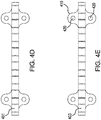
- FIGS 4A-4E show various views of an embodiment of a mounting bar 400, having a front wall 401, a rear wall 403, a top wall 405, and a bottom wall 406, wherein one or more tube retainers and/or tube retainer sets can be interlocked with the mounting bar.
- the illustrated mounting bar includes a front wall 401 having two or more female connectors 490, each female connector 490 comprising a recess 491 comprising a first lug pocket 492 having an open end 492A and a closed end 492B, and a second lug pocket 493 having an open end 493A and a closed end 493B, wherein the first lug pocket and the second lug pocket are arranged generally parallel to the front wall, wherein the recess further comprises a central indentation 494 between the first lug pocket and the second lug pocket.
- embodiments of the invention can be used with a variety of bioprocessing systems.
- tube retainers and tube retainer sets are utilized with a mounting bar that can be configured for attachment to a bioprocessing system before or after connection with interlocking tube retainers/tube retainer sets.
- the mounting bar can include one or more cut outs to allow hanging on an extending pin or screw, or flanges to allow mounting.
- the embodiment illustrated in Figures 4A-4E includes two mounting flanges 410, each including two mounting holes 420.
- Mounting bars can be mounted horizontally (e.g., as shown in Figure 6 ), vertically, or at an angle, on, for example, hardware, frame components, and/or stand alone "pylons" (e.g., vertical stands) for bridging gaps between skids.
- pylons e.g., vertical stands
- a tube management system comprising a mounting bar and at least one tube retainer and/or tube retainer set.
- Figure 5 shows an embodiment of a tube management system 500 comprising a mounting bar 400 and a plurality of tube retainers interlocked thereto, wherein the plurality of tube retainers are provided as a tube retainer set 300 (similar to that illustrated in Figure 3A with an additional tube retainer 100 (100C)).
- Figure 6 shows a bioprocessing system 1000 having the embodiment of the tube management system 500 shown in Figure 5 mounted to the bioprocessing system, also showing tubing of different outside diameters retained in tube retainers having differently sized second openings.
- embodiments of tube retainers and/or tube retainer sets can be interconnected and/or embodiments of the tube management systems can be assembled and tubes can be subsequently placed in the interlocking tube retainers and/or tube retainer sets, or tubes can be placed in interlocking tube retainers that are already interconnected with each other and/or with a mounting bar.
Landscapes
- Engineering & Computer Science (AREA)
- General Engineering & Computer Science (AREA)
- Mechanical Engineering (AREA)
- Quick-Acting Or Multi-Walled Pipe Joints (AREA)
- Supports For Pipes And Cables (AREA)
- Mutual Connection Of Rods And Tubes (AREA)
Abstract
Description
- Systems including tubing such as bioprocessing systems, particularly single-use systems, typically utilize flexible tubing to provide fluid communication between various components and for connecting fluid processes. The systems can include a number of tubes and/or a variety of tubes having different inside and/or outside diameters.
- The present invention provides for ameliorating at least some of the disadvantages of the prior art. These and other advantages of the present invention will be apparent from the description as set forth below.
- An embodiment of the invention provides a tube retainer comprising a block comprising a top wall; a bottom wall; a first side wall; a second side wall; a third side wall; and a fourth side wall; a first opening comprising a tube slot having a first slot end and a second slot end, and a second opening having a generally annular shape, the first opening communicating with the second opening, the first and second openings passing through the top wall and the bottom wall; wherein at least the first side wall and the second side wall each include a male block connector comprising a first extending arm having a free end including a lug facing perpendicularly to the first extending arm and generally parallel to the respective side wall, and a second extending arm having a free end including a lug facing perpendicularly to the second extending arm and generally parallel to the respective side wall, wherein the lug on the first ending arm and the lug on the second extending arm face away from each other, the male block connector further comprising an extending tongue between the first extending arm and the second extending arm; and/or a female block connector comprising a recess comprising a first lug pocket having an open end and a closed end, and a second lug pocket having an open end and a closed end, wherein the first lug pocket and the second lug pocket are arranged generally parallel to the respective side wall and the open end of the first lug pocket faces the open end of the second lug pocket, the recess further comprising a central indentation between the first lug pocket and the second lug pocket; wherein the third wall or the fourth wall includes the first slot end of the tube slot.
- In some embodiments of the tube retainer, the first side wall and the second side wall each include a male block connector and a female block connector.
- Another embodiment of the invention provides a tube retainer set comprising at least first and second tube retainers.
- Yet another embodiment of the invention relates to a tube retainer management system comprising at least one tube retainer, preferably, at least one tube retainer set, interlockable with a mounting bar.
- In other embodiments, methods of assembling and using the tube retainers, tube retainer sets, and tubing retainer management systems, are provided.
-
-
Figures 1A-1F illustrate a tube retainer comprising first and second side walls each including a male block connector comprising first and second extending arms, each arm having a free end including a lug, and an extending tongue between the extending arms, and third and fourth side walls each including a female block connector comprising a recess comprising a first lug pocket and a second lug pocket and a central indentation between the lug pockets according to an embodiment of the invention.Figure 1A shows a top view,Figure 1B shows a bottom view,Figure 1C shows a right side view,Figure 1D shows a left side view,Figure 1E shows a front view and Figure IF shows a rear view. -
Figures 2A-2F illustrate a tube retainer comprising first, second, third, and fourth side walls each including a male block connector comprising first and second extending arms each arm having a free end including a lug, and an extending tongue between the extending arms, wherein the first, second and third side walls each also include a female block connector comprising a recess comprising a first lug pocket and a second lug pocket and a central indentation between the lug pockets according to an embodiment of the invention.Figure 2A shows a top view,Figure 2B shows a bottom view,Figure 2C shows a right side view,Figure 2D shows a left side view,Figure 2E shows a front view andFigure 2F shows a rear view. -
Figure 3A shows a top view of a tube retainer set comprising two tube retainers as shown inFigures 1A-1F interlocked together, and two tube retainers as shown inFigures 2A-2F separately interlocked with the pair of tube retainers as shown inFigures 1A-1F .Figure 3B shows a top view of a tube retainer set comprising two tube retainers as shown inFigures 2A-2F interlocked together, and two tube retainers as shown inFigures 1A-1F separately interlocked with individual tube retainers as shown inFigures 2A-2F , according to an embodiment of the invention. -
Figures 4A-4E shows a mounting bar for the tube retainers as shown inFigures 1A-1E and2A-2E and the tube retainer sets shown inFigures 3A and 3B according to an embodiment of the invention.Figure 4A shows a top perspective view,Figure 4B shows a top view,Figure 4C shows a bottom view,Figure 4D shows a front view, andFigure 4E shows a rear view. -
Figure 5 shows a top view of tube management system including the tube retainer set as generally shown inFigure 3A (also including an additional tube retainer as shown inFigures 1A-1F ) interlocked with the mounting bar shown inFigures 4A-4E , according to an embodiment of the invention. -
Figure 6 shows the tube management system shown inFigure 5 mounted to a bioprocessing system according to an embodiment of the invention. - A tube retainer according to an embodiment of the invention comprises a block comprising a top wall; a bottom wall; a first side wall; a second side wall; a third side wall; and a fourth side wall; a first opening comprising a tube slot having a first slot end and a second slot end, and a second opening having a generally annular shape, the first opening communicating with the second opening, the first and second openings passing through the top wall and the bottom wall; wherein at least the first side wall and the second side wall each include a male block connector comprising a first extending arm having a free end including a lug facing perpendicularly to the first extending arm and generally parallel to the respective side wall, and a second extending arm having a free end including a lug facing perpendicularly to the second extending arm and generally parallel to the respective side wall, wherein the lug on the first ending arm and the lug on the second extending arm face away from each other, the male block connector further comprising an extending tongue between the first extending arm and the second extending arm; and/or a female block connector comprising a recess comprising a first lug pocket having an open end and a closed end, and a second lug pocket having an open end and a closed end, wherein the first lug pocket and the second lug pocket are arranged generally parallel to the respective side wall and the open end of the first lug pocket faces the open end of the second lug pocket, the recess further comprising a central indentation between the first lug pocket and the second lug pocket; wherein the third wall or the fourth wall includes the first slot end of the tube slot.
- A tube retainer according to another embodiment of the invention comprises a block comprising a top wall; a bottom wall; a first side wall; a second side wall; a third side wall; and a fourth side wall; a first opening comprising a tube slot having a first slot end and a second slot end, and a second opening having a generally annular shape, the first opening communicating with the second opening, the first and second openings passing through the top wall and the bottom wall; wherein at least the first side wall and the second side wall each include a male block connector comprising a first extending arm having a free end including a lug facing perpendicularly to the first extending arm and generally parallel to the side wall, and a second extending arm having a free end including a lug facing perpendicularly to the second extending arm and generally parallel to the side wall, wherein the lug on the first ending arm and the lug on the second extending arm face away from each other, the male block connector further comprising an extending tongue between the first extending arm and the second extending arm.
- A tube retainer according to another embodiment of the invention comprises a block comprising a top wall; a bottom wall; a first side wall; a second side wall; a third side wall; and a fourth side wall; a first opening comprising a tube slot having a first slot end and a second slot end, and a second opening having a generally annular shape, the first opening communicating with the second opening, the first and second openings passing through the top wall and the bottom wall; wherein at least the first side wall and the second side wall each include a female block connector comprising a recess comprising a first lug pocket having an open end and a closed end, and a second lug pocket having an open end and a closed end, wherein the first lug pocket and the second lug pocket are arranged generally parallel to the side wall and the open end of the first lug pocket faces the open end of the second lug pocket, the recess further comprising a central indentation between the first lug pocket and the second lug pocket; wherein the third wall or the fourth wall includes the first slot end of the tube slot.
- In some embodiments of the tube retainer, the first side wall and the second side wall each include a male block connector and a female block connector.
- A tube retainer according to yet another embodiment of the invention comprises a block comprising a top wall; a bottom wall; a first side wall; a second side wall; a third side wall; and a fourth side wall; a first opening comprising a tube slot having a first slot end and a second slot end, and a second opening having a generally annular shape, the first opening communicating with the second opening, the first and second openings passing through the top wall and the bottom wall; wherein at least the first side wall and the second side wall each include a male block connector comprising a first extending arm having a free end including a lug facing perpendicularly to the first extending arm and generally parallel to the side wall, and a second extending arm having a free end including a lug facing perpendicularly to the second extending arm and generally parallel to the side wall, wherein the lug on the first ending arm and the lug on the second extending arm face away from each other, the male block connector further comprising an extending tongue between the first extending arm and the second extending arm; and, a female block connector comprising a recess comprising a first lug pocket having an open end and a closed end, and a second lug pocket having an open end and a closed end, wherein the first lug pocket and the second lug pocket are arranged generally parallel to the side wall and the open end of the first lug pocket faces the open end of the second lug pocket, the recess further comprising a central indentation between the first lug pocket and the second lug pocket; wherein the third wall or the fourth wall includes the first slot end of the tube slot.
- Another embodiment of the invention provides a tube retainer set comprising at least first and second tube retainers.
- Yet another embodiment of the invention relates to a tube retainer management system comprising at least one tube retainer, preferably, at least one tube retainer set, and a mounting bar, wherein the at least one tube retainer, or the at least one tube retainer set, is interlockable with the mounting bar.
- An embodiment of a tube retainer management system comprises at least one tube retainer according to an embodiment of the invention and/or at least one tube retainer set according to an embodiment of the invention; and, a mounting bar for the at least one tube retainer and/or the at least one tube retainer set, the mounting bar comprising a front wall and at least two female block connectors, each female block connector comprising a recess comprising a first lug pocket having an open end and a closed end, and a second lug pocket having an open end and a closed end, wherein the first lug pocket and the second lug pocket are arranged generally parallel to the front wall and the open end of the first lug pocket faces the open end of the second lug pocket, the recess further comprising a central indentation between the first lug pocket and the second lug pocket.
- In other embodiments, methods of using the tube retainers, the tube retainer sets, and the tubing retainer management systems are provided.
- In an embodiment, a method of assembling tube retainers is provided, the method comprising interlocking a first tube retainer including a top wall; a bottom wall; a first side wall; a second side wall; a third side wall; and a fourth side wall; a first opening comprising a tube slot having a first slot end and a second slot end, and a second opening having a generally annular shape, the first opening communicating with the second opening, the first and second openings passing through the top wall and the bottom wall; the first tube retainer comprising at least one male block connector comprising a first extending arm having a free end including a lug facing perpendicularly to the first extending arm and generally parallel to the side wall, and a second extending arm having a free end including a lug facing perpendicularly to the second extending arm and generally parallel to the side wall, wherein the lug on the first ending arm and the lug on the second extending arm face away from each other, the male block connector further comprising an extending tongue between the first extending arm and the second extending arm with a second tube retainer with a second tube retainer including a top wall; a bottom wall; a first side wall; a second side wall; a third side wall; and a fourth side wall; a first opening comprising a tube slot having a first slot end and a second slot end, and a second opening having a generally annular shape, the first opening communicating with the second opening, the first and second openings passing through the top wall and the bottom wall; the second tube retainer comprising at least one female block connector comprising a recess comprising a first lug pocket having an open end and a closed end, and a second lug pocket having an open end and a closed end, wherein the first lug pocket and the second lug pocket are arranged generally parallel to the side wall and the open end of the first lug pocket faces the open end of the second lug pocket, the recess further comprising a central indentation between the first lug pocket and the second lug pocket; wherein the third wall or the fourth wall includes the first slot end of the tube slot such that the lugs of the first and second extending arms of the at least one male connector of the first tube retainer are engaged in the first and second lug pockets of the at least one female connector of the second tube retainer.
- In a typical embodiment, the method further comprises passing a tube through the tube slot and into the second opening of the first or second tube retainer, preferably the method further comprises passing a first tube through the tube slot and into the second opening of the first tube retainer, and passing a second tube through the tube slot and into the second opening of the second tube retainer.
- Advantageously, multiple tubes and/or tubes of different diameters can be safely secured in the tube retainers, tube retainer sets, and tube retainer management system, thus reducing the change of tangling, getting snagged on system components, accidental disassembly, and/or being tripped over. Additionally, tubing can be safely secured without damaging the tubing, and changes in the design of the bioprocessing system and/or temporary hardware in the bioprocessing system can be easily accommodated. The compact design of the tube retainers, tube retainer sets, and tube management system minimizes complexity and size.
- Embodiments of the invention can be utilized with any diameter tubing. While conventional tubing outside diameters are (in inches) 1/8, 1/4, 5/16, 3/8, 1/2, 5/8, 3/4, 1, and 1.5, other tubing diameters can also be used. Typically, embodiments of tube retainers as shown in
Figures 1A-1F are used with tubing outside diameters of 1/8 inches to 5/16 inches, and embodiments of tube retainers as shown inFigures 2A-2F are used with tubing outside diameters of 3/8 inches or more (e.g., 3/8 inches to 3/4 inches). - As used herein, systems including tubing include, for example, bioprocessing systems including fluid transfer lines such as bioreactor systems, buffer management systems, and filtration systems (e.g., involving tangential flow filtration, depth filtration, and/or polishing).
- Each of the components of the invention will now be described in more detail below, wherein like components have like reference numbers.
-
Figures 1A-1F show an embodiment of atube retainer 100 comprising ablock 175 comprising afirst side wall 101, asecond side wall 102, athird side wall 103, afourth side wall 104, atop wall 105, and abottom wall 106, and fourcorners fourth side wall 104 includes a first opening 151 comprising a tube slot 151' having afirst slot end 151A and asecond slot end 151B, the first opening communicating with asecond opening 152 having a generally annular shape, wherein the first and second openings pass through the top and bottom walls. - At least one side wall of tube retainer 100 (preferably, at least two side walls), comprises a
male block connector 180 comprising a first extendingarm 181 having afree end 181A including alug 181B facing perpendicularly to the first extending arm and generally parallel to the side wall, and a second extendingarm 182 having afree end 182A including alug 182B facing perpendicularly to the second extending arm and generally parallel to the side wall, wherein the lug on the first ending arm and the lug on the second extending arm face away from each other, the male block connector further comprising an extendingtongue 183 between the first extending arm and the second extending arm. - In the embodiment illustrated in
Figures 1A-1F ,first side wall 101 andsecond side wall 102 each include amale block connector 180 comprising a first extendingarm 181 having afree end 181A including alug 181B facing perpendicularly to the first extending arm and generally parallel to the respective side wall, and a second extendingarm 182 having afree end 182A including alug 182B facing perpendicularly to the second extending arm and generally parallel to the respective side wall, wherein the lug on the first ending arm and the lug on the second extending arm face away from each other, the male block connector further comprising an extendingtongue 183 between the first extending arm and the second extending arm. - At least one side wall of tube retainer 100 (preferably, at least two side walls), comprises a
female block connector 190/190' comprising arecess 191 comprising afirst lug pocket 192 having anopen end 192A and a closedend 192B, and asecond lug pocket 193 having anopen end 193A and a closedend 193B, wherein the first lug pocket and the second lug pocket are arranged generally parallel to the side wall and theopen end 192A of the first lug pocket faces theopen end 193A of the second lug pocket. In some embodiments, the recess of at least onefemale connector 190 further comprises acentral indentation 194 between the first lug pocket and the second lug pocket. In other embodiments, at least one female connector 190' lacks the central indentation as the side wall including the female connector includes thefirst slot end 151A of the tube slot. - In the embodiment illustrated in
Figures 1A-1F ,third side wall 103 andfourth side wall 104 each include a female block connector, whereinthird side wall 103 comprisesfemale block connector 190 comprising arecess 191 comprising afirst lug pocket 192 having anopen end 192A and a closedend 192B, and asecond lug pocket 193 having anopen end 193A and a closedend 193B, wherein the first lug pocket and the second lug pocket are arranged generally parallel to the third side wall and theopen end 192A of the first lug pocket faces theopen end 193A of the second lug pocket, wherein the recess further comprises acentral indentation 194 between the first lug pocket and the second lug pocket, andfourth side wall 104 comprises female block connector 190' comprising arecess 191 comprising afirst lug pocket 192 having anopen end 192A and a closedend 192B, and asecond lug pocket 193 having anopen end 193A and a closedend 193B, wherein the first lug pocket and the second lug pocket are arranged generally parallel to the fourth side wall and theopen end 192A of the first lug pocket faces theopen end 193A of the second lug pocket, wherein the female block connector lacks the central indentation as theside wall 104 including the female connector includes thefirst slot end 151A of the tube slot. -
Figures 2A-2F show an embodiment of atube retainer 200, wherein the illustrated embodiment oftube retainer 200 has some similarities to the embodiment of thetube retainer 100 as illustrated inFigures 1A-1F . While the embodiment oftube retainer 100 as illustrated inFigures 1A-1F has male block connectors and female block connectors separately associated with separate side walls, the embodiment oftube retainer 200 as illustrated inFigures 2A-2F has both male block connectors and female block connectors associated the same side wall, preferably, at least two side walls each have at least one male block connectors and at least one female block connector. -
Figures 2A-2F show an embodiment of atube retainer 200 comprising ablock 275 comprising afirst side wall 201, asecond side wall 202, athird side wall 203, afourth side wall 204, atop wall 205, and abottom wall 206, and fourcorners fourth side wall 204 includes afirst opening 251 comprising a tube slot 251' having afirst slot end 251A and asecond slot end 251B, the first opening communicating with asecond opening 252 having a generally annular shape, wherein the first and second openings pass through the top and bottom walls. - At least one side wall of tube retainer 200 (preferably, at least two side walls), comprises (in addition to a female block connector as discussed below) a
male block connector 280 comprising a first extendingarm 281 having afree end 281A including alug 281B facing perpendicularly to the first extending arm and generally parallel to the side wall, and a second extendingarm 282 having afree end 182A including alug 282B facing perpendicularly to the second extending arm and generally parallel to the side wall, wherein the lug on the first ending arm and the lug on the second extending arm face away from each other, the male block connector further comprising an extendingtongue 283 between the first extending arm and the second extending arm. - In the embodiment illustrated in
Figures 2A-2F ,first side wall 201,second side wall 202,third side wall 203, andfourth side wall 204, each include amale block connector 280 comprising a first extendingarm 281 having afree end 281A including alug 281B facing perpendicularly to the first extending arm and generally parallel to the respective side wall, and a second extendingarm 282 having afree end 282A including alug 282B facing perpendicularly to the second extending arm and generally parallel to the respective side wall, wherein the lug on the first ending arm and the lug on the second extending arm face away from each other, the male block connector further comprising an extendingtongue 283 between the first extending arm and the second extending arm. - At least one side wall of tube retainer 200 (preferably, at least two side walls), comprises (in addition to the male block connector as discussed above) a
female block connector 290 comprising arecess 291 comprising afirst lug pocket 292 having anopen end 292A and a closedend 292B, and asecond lug pocket 293 having anopen end 293A and a closedend 293B, wherein the first lug pocket and the second lug pocket are arranged generally parallel to the side wall and theopen end 292A of the first lug pocket faces theopen end 293A of the second lug pocket, and wherein the recess further comprises acentral indentation 294 between the first lug pocket and the second lug pocket. - In the illustrated embodiments, at least one female block connector 290' comprises a
recess 291 comprising afirst lug pocket 292 having anopen end 292A and a closedend 292B, wherein the first lug pocket is arranged generally parallel to the side wall, and wherein the recess further comprises acentral indentation 294 near the first lug pocket. However, the illustrated female block connector 290' lacks one lug pocket as the side wall including the female connector 290' includes thefirst slot end 151A of the tube slot. - In the embodiment illustrated in
Figures 2A-2F ,first side wall 201,second side wall 202, andthird side wall 203, each include afemale block connector 290 comprising arecess 291 comprising afirst lug pocket 292 having anopen end 292A and a closedend 292B, and asecond lug pocket 293 having anopen end 293A and a closedend 293B, wherein the first lug pocket and the second lug pocket are arranged generally parallel to the respective side wall and theopen end 292A of the first lug pocket faces theopen end 293A of the second lug pocket, wherein the recess further comprises acentral indentation 294 between the first lug pocket and the second lug pocket. In the embodiment illustrated inFigures 2A-2F ,fourth side wall 204 comprises female block connector 290' comprising arecess 291 comprising afirst lug pocket 292 arranged generally parallel to the side wall, the lug pocket having anopen end 292A and a closedend 292B, and acentral indentation 294 near the first lug pocket, wherein the female block connector 290' lacks one lug pocket as the side wall including the female connector 290' includes thefirst slot end 251A of the tube slot. - Tubing is inserted in a tube retainer by passing it through the tubing slot into the second opening which has a generally annular shape. The tubing is compressed as it passes through the slot, and expands to its regular diameter once located in the second opening. If desired, the first end of the tube slot can be closed by interlocking the tube retainer with a second tube retainer such that an extending tongue of the male connector of the second tube retainer fits in the first end of the tube slot of the first tube retainer (see, for example,
Figure 6 ). However, since the tubing has expanded to its regular diameter once within the second opening, even if the first end of the tube slot is not closed, the tubing will not fall out of the tube retainer in the absence of force. - Typically, a plurality of tube retainers are utilized at one time, thus providing a tube retainer set. Tube retainers can typically be slid, pushed and/or snapped together, such that the male block connector(s) engage and interlock with the corresponding female block connector(s).
- A tube retainer set can comprise two or more embodiments of tube retainers as illustrated in
Figures 1A-1F , two or more embodiments of tube retainers as illustrated inFigures 2A-2F , and/or at least one embodiment of a tube retainer as illustrated inFigures 1A-1F and at least one embodiment of a tube retainer as illustrated inFigures 2A-2F . - Illustratively,
Figures 3A and 3B illustrate various embodiments of tube retainer sets. For example,Figure 3A shows several embodiments of a tube retainer set 300 (including twotube retainers 100 interlocked together), andFigure 3B shows several embodiments of a tube retainer set 300' (including twotube retainers 200 interlocked together) wherein two or more tube retainers are interlocked in various configurations, e.g., two tube retainers 100 (100A and 100B), or two tube retainers 200 (200A and 200B), or three tube retainers, or four tube retainers. - With respect to interlocking, as shown in
Figures 3A, 3B , and5 , the lugs of the first and second extending arms of the male connectors of the tube retainers are engaged in, e.g., fit snugly in, the first and second lug pockets of the female connectors of the tube retainers and of the female connectors of the mounting bar (mounting bar discussed below, see also,Figure 5 ), and the extending tongues of the male connectors of the tube retainers fit in the central indentations of the female connectors of the tube retainers and mounting bar. During interlocking, the tube retainers can be slid together in the Z axis, or can be pushed/snapped together in the X axis as the arms deflect. Contact between the outer surfaces of thecorners 199A-199D and/or 299A-299D and/or thefront wall 401 of the mounting bar assists in maintaining the interlocking between the tube retainers. Tube retainers can be decoupled by sliding in the Z axis. - In some configurations, some of the extending tongues of the male connectors of the tube retainers fit into the first ends of tube slots (see, for example, the interlocking of
tube retainer 100B andtube retainer 200A inFigure 3A , and the interlocking oftube retainer 100A andtube retainer 100B inFigure 5 ), wherein tubing can be fully encircled by portions of the tube retainers as shown inFigure 6 . - Typically, tube retainers and tube retainer sets are utilized with a mounting bar.
-
Figures 4A-4E show various views of an embodiment of a mountingbar 400, having afront wall 401, arear wall 403, atop wall 405, and abottom wall 406, wherein one or more tube retainers and/or tube retainer sets can be interlocked with the mounting bar. Using the embodiment shown inFigures 4A and 4B for reference, the illustrated mounting bar includes afront wall 401 having two or morefemale connectors 490, eachfemale connector 490 comprising arecess 491 comprising afirst lug pocket 492 having anopen end 492A and aclosed end 492B, and asecond lug pocket 493 having anopen end 493A and aclosed end 493B, wherein the first lug pocket and the second lug pocket are arranged generally parallel to the front wall, wherein the recess further comprises acentral indentation 494 between the first lug pocket and the second lug pocket. - As noted above, embodiments of the invention can be used with a variety of bioprocessing systems. Typically, tube retainers and tube retainer sets are utilized with a mounting bar that can be configured for attachment to a bioprocessing system before or after connection with interlocking tube retainers/tube retainer sets. For example, the mounting bar can include one or more cut outs to allow hanging on an extending pin or screw, or flanges to allow mounting. The embodiment illustrated in
Figures 4A-4E includes two mountingflanges 410, each including two mountingholes 420. Mounting bars can be mounted horizontally (e.g., as shown inFigure 6 ), vertically, or at an angle, on, for example, hardware, frame components, and/or stand alone "pylons" (e.g., vertical stands) for bridging gaps between skids. - In accordance with another embodiment of the invention, a tube management system is provided comprising a mounting bar and at least one tube retainer and/or tube retainer set.
- For example,
Figure 5 shows an embodiment of atube management system 500 comprising a mountingbar 400 and a plurality of tube retainers interlocked thereto, wherein the plurality of tube retainers are provided as a tube retainer set 300 (similar to that illustrated inFigure 3A with an additional tube retainer 100 (100C)). -
Figure 6 shows abioprocessing system 1000 having the embodiment of thetube management system 500 shown inFigure 5 mounted to the bioprocessing system, also showing tubing of different outside diameters retained in tube retainers having differently sized second openings. - In accordance with embodiments of methods of retaining tubes according to the invention, embodiments of tube retainers and/or tube retainer sets can be interconnected and/or embodiments of the tube management systems can be assembled and tubes can be subsequently placed in the interlocking tube retainers and/or tube retainer sets, or tubes can be placed in interlocking tube retainers that are already interconnected with each other and/or with a mounting bar.
- All references, including publications, patent applications, and patents, cited herein are hereby incorporated by reference to the same extent as if each reference were individually and specifically indicated to be incorporated by reference and were set forth in its entirety herein.
- The use of the terms "a" and "an" and "the" and "at least one" and similar referents in the context of describing the invention (especially in the context of the following claims) are to be construed to cover both the singular and the plural, unless otherwise indicated herein or clearly contradicted by context. The use of the term "at least one" followed by a list of one or more items (for example, "at least one of A and B") is to be construed to mean one item selected from the listed items (A or B) or any combination of two or more of the listed items (A and B), unless otherwise indicated herein or clearly contradicted by context. The terms "comprising," "having," "including," and "containing" are to be construed as open-ended terms (i.e., meaning "including, but not limited to,") unless otherwise noted. Recitation of ranges of values herein are merely intended to serve as a shorthand method of referring individually to each separate value falling within the range, unless otherwise indicated herein, and each separate value is incorporated into the specification as if it were individually recited herein. All methods described herein can be performed in any suitable order unless otherwise indicated herein or otherwise clearly contradicted by context. The use of any and all examples, or exemplary language (e.g., "such as") provided herein, is intended merely to better illuminate the invention and does not pose a limitation on the scope of the invention unless otherwise claimed. No language in the specification should be construed as indicating any non-claimed element as essential to the practice of the invention.
- Preferred embodiments of this invention are described herein, including the best mode known to the inventors for carrying out the invention. Variations of those preferred embodiments may become apparent to those of ordinary skill in the art upon reading the foregoing description. The inventors expect skilled artisans to employ such variations as appropriate, and the inventors intend for the invention to be practiced otherwise than as specifically described herein. Accordingly, this invention includes all modifications and equivalents of the subject matter recited in the claims appended hereto as permitted by applicable law. Moreover, any combination of the above-described elements in all possible variations thereof is encompassed by the invention unless otherwise indicated herein or otherwise clearly contradicted by context.
Claims (8)
- A tube retainer comprising:
a block comprising:a top wall;a bottom wall;a first side wall;a second side wall;a third side wall; anda fourth side wall;a first opening comprising a tube slot having a first slot end and a second slot end, anda second opening having a generally annular shape, the first opening communicating with the second opening, the first and second openings passing through the top wall and the bottom wall;wherein at least the first side wall and the second side wall each includea male block connector comprising a first extending arm having a free end including a lug facing perpendicularly to the first extending arm and generally parallel to the side wall, and a second extending arm having a free end including a lug facing perpendicularly to the second extending arm and generally parallel to the side wall, wherein the lug on the first ending arm and the lug on the second extending arm face away from each other, the male block connector further comprising an extending tongue between the first extending arm and the second extending arm;
and/ora female block connector comprising a recess comprising a first lug pocket having an open end and a closed end, and a second lug pocket having an open end and a closed end, wherein the first lug pocket and the second lug pocket are arranged generally parallel to the side wall and the open end of the first lug pocket faces the open end of the second lug pocket, the recess further comprising a central indentation between the first lug pocket and the second lug pocket;wherein the third wall or the fourth wall includes the first slot end of the tube slot. - The tube retainer of claim 1, wherein the first side wall and the second side wall each include a male block connector and a female block connector.
- A tube retainer set comprising at least two tube retainers according to claim 1 and/or claim 2.
- A tube management system comprising:at least one tube retainer according to claim 1 or 2 and/or at least one tube retainer set according to claim 3; and,a mounting bar for the at least one tube retainer and/or the at least one tube retainer set, the mounting bar comprising a front wall and at least two female block connectors, each female block connector comprising a recess comprising a first lug pocket having an open end and a closed end, and a second lug pocket having an open end and a closed end, wherein the first lug pocket and the second lug pocket are arranged generally parallel to the front wall and the open end of the first lug pocket faces the open end of the second lug pocket, the recess further comprising a central indentation between the first lug pocket and the second lug pocket.
- The tube management system of claim 4, wherein the mounting bar includes a flange for attachment to a bioprocessing system.
- A method of assembling tube retainers, the method comprising:interlocking a first tube retainer including a top wall; a bottom wall; a first side wall; a second side wall; a third side wall; and a fourth side wall; a first opening comprising a tube slot having a first slot end and a second slot end, and a second opening having a generally annular shape, the first opening communicating with the second opening, the first and second openings passing through the top wall and the bottom wall; the first tube retainer comprising at least one male block connector comprising a first extending arm having a free end including a lug facing perpendicularly to the first extending arm and generally parallel to the side wall, and a second extending arm having a free end including a lug facing perpendicularly to the second extending arm and generally parallel to the side wall, wherein the lug on the first ending arm and the lug on the second extending arm face away from each other, the male block connector further comprising an extending tongue between the first extending arm and the second extending arm with a second tube retainerwitha second tube retainer including a top wall; a bottom wall; a first side wall; a second side wall; a third side wall; and a fourth side wall; a first opening comprising a tube slot having a first slot end and a second slot end, and a second opening having a generally annular shape, the first opening communicating with the second opening, the first and second openings passing through the top wall and the bottom wall; the second tube retainer comprising at least one female block connector comprising a recess comprising a first lug pocket having an open end and a closed end, and a second lug pocket having an open end and a closed end, wherein the first lug pocket and the second lug pocket are arranged generally parallel to the side wall and the open end of the first lug pocket faces the open end of the second lug pocket, the recess further comprising a central indentation between the first lug pocket and the second lug pocket; wherein the third wall or the fourth wall includes the first slot end of the tube slotsuch that the lugs of the first and second extending arms of the at least one male connector of the first tube retainer are engaged in the first and second lug pockets of the at least one female connector of the second tube retainer.
- The method of claim 6, further comprising passing a first tube through the tube slot and into the second opening of the first tube retainer.
- The method of claim 7, further comprising passing a second tube through the tube slot and into the second opening of the second tube retainer.
Applications Claiming Priority (1)
| Application Number | Priority Date | Filing Date | Title |
|---|---|---|---|
| US16/832,586 US11384869B2 (en) | 2020-03-27 | 2020-03-27 | Tube retainers, tube retainer sets, and tube management systems |
Publications (2)
| Publication Number | Publication Date |
|---|---|
| EP3885619A1 true EP3885619A1 (en) | 2021-09-29 |
| EP3885619B1 EP3885619B1 (en) | 2023-12-27 |
Family
ID=74758626
Family Applications (1)
| Application Number | Title | Priority Date | Filing Date |
|---|---|---|---|
| EP21159253.0A Active EP3885619B1 (en) | 2020-03-27 | 2021-02-25 | Tube retainers, tube retainer sets, tube management systems and method |
Country Status (6)
| Country | Link |
|---|---|
| US (1) | US11384869B2 (en) |
| EP (1) | EP3885619B1 (en) |
| JP (1) | JP7055948B2 (en) |
| KR (1) | KR102522704B1 (en) |
| CN (1) | CN113446436B (en) |
| SG (1) | SG10202102144QA (en) |
Families Citing this family (2)
| Publication number | Priority date | Publication date | Assignee | Title |
|---|---|---|---|---|
| US11519541B2 (en) | 2020-03-27 | 2022-12-06 | Pall Corporation | Tube retainers, tube retainer sets, and tube management systems |
| USD1116708S1 (en) * | 2023-10-30 | 2026-03-10 | Chewy, Inc. | Sorter clip |
Citations (4)
| Publication number | Priority date | Publication date | Assignee | Title |
|---|---|---|---|---|
| US20080105796A1 (en) * | 2006-11-08 | 2008-05-08 | International Truck Intellectual Property Company, Llc | Modular route and clip system |
| US20170122462A1 (en) * | 2015-11-04 | 2017-05-04 | Fkb Gmbh | Guiding or holding device for receiving pipes, cables or flexible tubes |
| US20170258984A1 (en) * | 2016-03-11 | 2017-09-14 | Variety Children's Hospital d/b/a Nicklaus Children's Hospital | Medical bedside safety modular apparatus and method |
| DE202019100169U1 (en) * | 2019-01-14 | 2020-02-20 | Igus Gmbh | Compact flexible cable protection system, especially for clean room applications |
Family Cites Families (22)
| Publication number | Priority date | Publication date | Assignee | Title |
|---|---|---|---|---|
| FR2257842B1 (en) | 1973-07-03 | 1976-05-28 | Legris France Sa | |
| DE2624333C2 (en) * | 1976-05-31 | 1984-07-05 | Hilti Ag, Schaan | clamp |
| US4306697A (en) * | 1980-06-16 | 1981-12-22 | Mathews Lyle H | Conduit spacer system |
| DE3824197A1 (en) | 1988-07-16 | 1990-01-18 | Theodor Stratmann | Pipe clamp |
| JPH0692888B2 (en) * | 1990-01-10 | 1994-11-16 | 新日本製鐵株式会社 | X-ray CT system |
| US4999885A (en) * | 1990-03-01 | 1991-03-19 | Lee Michael D | Device for maintaining orderly tubing or wiring |
| JPH07280139A (en) * | 1994-04-11 | 1995-10-27 | Tigers Polymer Corp | Spacer for buried pipe |
| JP2891408B2 (en) * | 1996-06-25 | 1999-05-17 | 豊田油気株式会社 | Hose holder |
| CA2605426C (en) | 2005-04-18 | 2016-02-09 | Q-Ba-Maze Inc. | Interconnecting modular pathway apparatus |
| JP2007002953A (en) | 2005-06-27 | 2007-01-11 | Nippon Pop Rivets & Fasteners Ltd | Tube clamp |
| US8342474B2 (en) | 2008-03-07 | 2013-01-01 | The Gates Corporation | Modular support, assemblies, methods and systems |
| US8020259B2 (en) | 2008-06-02 | 2011-09-20 | Cyber Power Systems Inc. | Cable clamp and cable clamp assembly |
| US8910912B2 (en) * | 2009-09-02 | 2014-12-16 | Illinois Tool Works Inc. | Conductive floating pipe assembly clip |
| GB201009963D0 (en) * | 2010-06-15 | 2010-07-21 | Airbus Operations Ltd | Modular conduit retntion system |
| CN105026814B (en) | 2013-03-29 | 2018-02-09 | 伊利诺斯工具制品有限公司 | Tube Retention Clip Assembly |
| DE102013219741A1 (en) * | 2013-09-30 | 2015-04-02 | Deere & Co. | Clamp and clamping device with such and frame construction with such a clamping device |
| US10151406B2 (en) * | 2017-03-17 | 2018-12-11 | Illinois Tool Works Inc. | Clamp assembly for holding vehicle parts |
| CN209767104U (en) * | 2018-12-07 | 2019-12-10 | 江苏迈道通信科技有限公司 | Cable installation device and cable clamp thereof |
| WO2020148596A1 (en) | 2019-01-14 | 2020-07-23 | Igus Gmbh | Compact conduit for clean room applications, and casing and clamping fixture for said conduit |
| US11662041B2 (en) * | 2019-07-29 | 2023-05-30 | Erico International Corporation | Support clip |
| US11255467B2 (en) * | 2019-08-28 | 2022-02-22 | Deere & Company | Hose retainer |
| US11519541B2 (en) | 2020-03-27 | 2022-12-06 | Pall Corporation | Tube retainers, tube retainer sets, and tube management systems |
-
2020
- 2020-03-27 US US16/832,586 patent/US11384869B2/en active Active
-
2021
- 2021-02-24 JP JP2021027353A patent/JP7055948B2/en active Active
- 2021-02-25 EP EP21159253.0A patent/EP3885619B1/en active Active
- 2021-03-03 SG SG10202102144Q patent/SG10202102144QA/en unknown
- 2021-03-26 KR KR1020210039789A patent/KR102522704B1/en active Active
- 2021-03-26 CN CN202110323284.8A patent/CN113446436B/en active Active
Patent Citations (4)
| Publication number | Priority date | Publication date | Assignee | Title |
|---|---|---|---|---|
| US20080105796A1 (en) * | 2006-11-08 | 2008-05-08 | International Truck Intellectual Property Company, Llc | Modular route and clip system |
| US20170122462A1 (en) * | 2015-11-04 | 2017-05-04 | Fkb Gmbh | Guiding or holding device for receiving pipes, cables or flexible tubes |
| US20170258984A1 (en) * | 2016-03-11 | 2017-09-14 | Variety Children's Hospital d/b/a Nicklaus Children's Hospital | Medical bedside safety modular apparatus and method |
| DE202019100169U1 (en) * | 2019-01-14 | 2020-02-20 | Igus Gmbh | Compact flexible cable protection system, especially for clean room applications |
Also Published As
| Publication number | Publication date |
|---|---|
| EP3885619B1 (en) | 2023-12-27 |
| SG10202102144QA (en) | 2021-10-28 |
| KR102522704B1 (en) | 2023-04-18 |
| KR20210120907A (en) | 2021-10-07 |
| JP2021179248A (en) | 2021-11-18 |
| US20210301949A1 (en) | 2021-09-30 |
| CN113446436B (en) | 2022-07-29 |
| CN113446436A (en) | 2021-09-28 |
| JP7055948B2 (en) | 2022-04-19 |
| US11384869B2 (en) | 2022-07-12 |
Similar Documents
| Publication | Publication Date | Title |
|---|---|---|
| US6118075A (en) | Stackable universal pitch cable trough system | |
| EP3885620A1 (en) | Tube retainers, tube retainer sets, and tube management systems | |
| SG10202102144QA (en) | Tube retainers, tube retainer sets, and tube management systems | |
| US6242698B1 (en) | Interchangeable adapter face plates | |
| US7128595B2 (en) | Electrical connector with positive lock | |
| US20030220008A1 (en) | Axial latch actuator | |
| EP1653566A1 (en) | Axial latch actuator with locking wedge | |
| US20050079750A1 (en) | Modular plug with locking member | |
| WO2008112986A1 (en) | Single boot for duplex fiber optic connectors | |
| US9960518B2 (en) | Electrical cable connector and connector assembly thereof | |
| US4902247A (en) | Electrical connector | |
| US20210382238A1 (en) | Multiport assembly and associated components | |
| US5839922A (en) | 110 wiring block interlock and interlocked blocks utilizing such | |
| CN112260002B (en) | Magnetic cable adapter and connector and method for installing cables for realizing same | |
| US12298569B2 (en) | Guide pin holder for guide pins in an adapter | |
| EP3729567B1 (en) | Hermaphroditic electrical cable connector | |
| US7493005B2 (en) | Coupler for cable trough | |
| EP3832808B1 (en) | Modular fixing system and method thereof | |
| EP3093931A1 (en) | Splitter terminal and connector | |
| GB2535437A (en) | Pipe clip | |
| US6080010A (en) | Bracket design for a back to back individual strain relief of two modular connectors | |
| US20190312377A1 (en) | Multi-piece cassette | |
| CN120226217A (en) | Electrical connector with visual and tactile indication of proper independent secondary lock positioning | |
| EP1322008A1 (en) | System comprising a patch panel |
Legal Events
| Date | Code | Title | Description |
|---|---|---|---|
| PUAI | Public reference made under article 153(3) epc to a published international application that has entered the european phase |
Free format text: ORIGINAL CODE: 0009012 |
|
| STAA | Information on the status of an ep patent application or granted ep patent |
Free format text: STATUS: THE APPLICATION HAS BEEN PUBLISHED |
|
| AK | Designated contracting states |
Kind code of ref document: A1 Designated state(s): AL AT BE BG CH CY CZ DE DK EE ES FI FR GB GR HR HU IE IS IT LI LT LU LV MC MK MT NL NO PL PT RO RS SE SI SK SM TR |
|
| STAA | Information on the status of an ep patent application or granted ep patent |
Free format text: STATUS: REQUEST FOR EXAMINATION WAS MADE |
|
| 17P | Request for examination filed |
Effective date: 20220304 |
|
| RBV | Designated contracting states (corrected) |
Designated state(s): AL AT BE BG CH CY CZ DE DK EE ES FI FR GB GR HR HU IE IS IT LI LT LU LV MC MK MT NL NO PL PT RO RS SE SI SK SM TR |
|
| GRAP | Despatch of communication of intention to grant a patent |
Free format text: ORIGINAL CODE: EPIDOSNIGR1 |
|
| STAA | Information on the status of an ep patent application or granted ep patent |
Free format text: STATUS: GRANT OF PATENT IS INTENDED |
|
| INTG | Intention to grant announced |
Effective date: 20230217 |
|
| GRAS | Grant fee paid |
Free format text: ORIGINAL CODE: EPIDOSNIGR3 |
|
| GRAC | Information related to communication of intention to grant a patent modified |
Free format text: ORIGINAL CODE: EPIDOSCIGR1 |
|
| P01 | Opt-out of the competence of the unified patent court (upc) registered |
Effective date: 20230530 |
|
| INTG | Intention to grant announced |
Effective date: 20230217 |
|
| GRAA | (expected) grant |
Free format text: ORIGINAL CODE: 0009210 |
|
| STAA | Information on the status of an ep patent application or granted ep patent |
Free format text: STATUS: THE PATENT HAS BEEN GRANTED |
|
| AK | Designated contracting states |
Kind code of ref document: B1 Designated state(s): AL AT BE BG CH CY CZ DE DK EE ES FI FR GB GR HR HU IE IS IT LI LT LU LV MC MK MT NL NO PL PT RO RS SE SI SK SM TR |
|
| REG | Reference to a national code |
Ref country code: GB Ref legal event code: FG4D |
|
| REG | Reference to a national code |
Ref country code: CH Ref legal event code: EP |
|
| REG | Reference to a national code |
Ref country code: DE Ref legal event code: R096 Ref document number: 602021007976 Country of ref document: DE |
|
| REG | Reference to a national code |
Ref country code: IE Ref legal event code: FG4D |
|
| REG | Reference to a national code |
Ref country code: NL Ref legal event code: FP |
|
| REG | Reference to a national code |
Ref country code: SE Ref legal event code: TRGR |
|
| PG25 | Lapsed in a contracting state [announced via postgrant information from national office to epo] |
Ref country code: GR Free format text: LAPSE BECAUSE OF FAILURE TO SUBMIT A TRANSLATION OF THE DESCRIPTION OR TO PAY THE FEE WITHIN THE PRESCRIBED TIME-LIMIT Effective date: 20240328 |
|
| REG | Reference to a national code |
Ref country code: LT Ref legal event code: MG9D |
|
| PG25 | Lapsed in a contracting state [announced via postgrant information from national office to epo] |
Ref country code: LT Free format text: LAPSE BECAUSE OF FAILURE TO SUBMIT A TRANSLATION OF THE DESCRIPTION OR TO PAY THE FEE WITHIN THE PRESCRIBED TIME-LIMIT Effective date: 20231227 |
|
| PG25 | Lapsed in a contracting state [announced via postgrant information from national office to epo] |
Ref country code: ES Free format text: LAPSE BECAUSE OF FAILURE TO SUBMIT A TRANSLATION OF THE DESCRIPTION OR TO PAY THE FEE WITHIN THE PRESCRIBED TIME-LIMIT Effective date: 20231227 |
|
| PG25 | Lapsed in a contracting state [announced via postgrant information from national office to epo] |
Ref country code: LT Free format text: LAPSE BECAUSE OF FAILURE TO SUBMIT A TRANSLATION OF THE DESCRIPTION OR TO PAY THE FEE WITHIN THE PRESCRIBED TIME-LIMIT Effective date: 20231227 Ref country code: GR Free format text: LAPSE BECAUSE OF FAILURE TO SUBMIT A TRANSLATION OF THE DESCRIPTION OR TO PAY THE FEE WITHIN THE PRESCRIBED TIME-LIMIT Effective date: 20240328 Ref country code: FI Free format text: LAPSE BECAUSE OF FAILURE TO SUBMIT A TRANSLATION OF THE DESCRIPTION OR TO PAY THE FEE WITHIN THE PRESCRIBED TIME-LIMIT Effective date: 20231227 Ref country code: ES Free format text: LAPSE BECAUSE OF FAILURE TO SUBMIT A TRANSLATION OF THE DESCRIPTION OR TO PAY THE FEE WITHIN THE PRESCRIBED TIME-LIMIT Effective date: 20231227 Ref country code: BG Free format text: LAPSE BECAUSE OF FAILURE TO SUBMIT A TRANSLATION OF THE DESCRIPTION OR TO PAY THE FEE WITHIN THE PRESCRIBED TIME-LIMIT Effective date: 20240327 |
|
| REG | Reference to a national code |
Ref country code: AT Ref legal event code: MK05 Ref document number: 1644815 Country of ref document: AT Kind code of ref document: T Effective date: 20231227 |
|
| PG25 | Lapsed in a contracting state [announced via postgrant information from national office to epo] |
Ref country code: RS Free format text: LAPSE BECAUSE OF FAILURE TO SUBMIT A TRANSLATION OF THE DESCRIPTION OR TO PAY THE FEE WITHIN THE PRESCRIBED TIME-LIMIT Effective date: 20231227 Ref country code: NO Free format text: LAPSE BECAUSE OF FAILURE TO SUBMIT A TRANSLATION OF THE DESCRIPTION OR TO PAY THE FEE WITHIN THE PRESCRIBED TIME-LIMIT Effective date: 20240327 Ref country code: LV Free format text: LAPSE BECAUSE OF FAILURE TO SUBMIT A TRANSLATION OF THE DESCRIPTION OR TO PAY THE FEE WITHIN THE PRESCRIBED TIME-LIMIT Effective date: 20231227 Ref country code: HR Free format text: LAPSE BECAUSE OF FAILURE TO SUBMIT A TRANSLATION OF THE DESCRIPTION OR TO PAY THE FEE WITHIN THE PRESCRIBED TIME-LIMIT Effective date: 20231227 |
|
| PG25 | Lapsed in a contracting state [announced via postgrant information from national office to epo] |
Ref country code: IS Free format text: LAPSE BECAUSE OF FAILURE TO SUBMIT A TRANSLATION OF THE DESCRIPTION OR TO PAY THE FEE WITHIN THE PRESCRIBED TIME-LIMIT Effective date: 20240427 |
|
| PG25 | Lapsed in a contracting state [announced via postgrant information from national office to epo] |
Ref country code: CZ Free format text: LAPSE BECAUSE OF FAILURE TO SUBMIT A TRANSLATION OF THE DESCRIPTION OR TO PAY THE FEE WITHIN THE PRESCRIBED TIME-LIMIT Effective date: 20231227 Ref country code: AT Free format text: LAPSE BECAUSE OF FAILURE TO SUBMIT A TRANSLATION OF THE DESCRIPTION OR TO PAY THE FEE WITHIN THE PRESCRIBED TIME-LIMIT Effective date: 20231227 |
|
| PG25 | Lapsed in a contracting state [announced via postgrant information from national office to epo] |
Ref country code: SK Free format text: LAPSE BECAUSE OF FAILURE TO SUBMIT A TRANSLATION OF THE DESCRIPTION OR TO PAY THE FEE WITHIN THE PRESCRIBED TIME-LIMIT Effective date: 20231227 |
|
| PG25 | Lapsed in a contracting state [announced via postgrant information from national office to epo] |
Ref country code: SM Free format text: LAPSE BECAUSE OF FAILURE TO SUBMIT A TRANSLATION OF THE DESCRIPTION OR TO PAY THE FEE WITHIN THE PRESCRIBED TIME-LIMIT Effective date: 20231227 Ref country code: SK Free format text: LAPSE BECAUSE OF FAILURE TO SUBMIT A TRANSLATION OF THE DESCRIPTION OR TO PAY THE FEE WITHIN THE PRESCRIBED TIME-LIMIT Effective date: 20231227 Ref country code: RO Free format text: LAPSE BECAUSE OF FAILURE TO SUBMIT A TRANSLATION OF THE DESCRIPTION OR TO PAY THE FEE WITHIN THE PRESCRIBED TIME-LIMIT Effective date: 20231227 Ref country code: IS Free format text: LAPSE BECAUSE OF FAILURE TO SUBMIT A TRANSLATION OF THE DESCRIPTION OR TO PAY THE FEE WITHIN THE PRESCRIBED TIME-LIMIT Effective date: 20240427 Ref country code: EE Free format text: LAPSE BECAUSE OF FAILURE TO SUBMIT A TRANSLATION OF THE DESCRIPTION OR TO PAY THE FEE WITHIN THE PRESCRIBED TIME-LIMIT Effective date: 20231227 Ref country code: CZ Free format text: LAPSE BECAUSE OF FAILURE TO SUBMIT A TRANSLATION OF THE DESCRIPTION OR TO PAY THE FEE WITHIN THE PRESCRIBED TIME-LIMIT Effective date: 20231227 Ref country code: AT Free format text: LAPSE BECAUSE OF FAILURE TO SUBMIT A TRANSLATION OF THE DESCRIPTION OR TO PAY THE FEE WITHIN THE PRESCRIBED TIME-LIMIT Effective date: 20231227 |
|
| PG25 | Lapsed in a contracting state [announced via postgrant information from national office to epo] |
Ref country code: PT Free format text: LAPSE BECAUSE OF FAILURE TO SUBMIT A TRANSLATION OF THE DESCRIPTION OR TO PAY THE FEE WITHIN THE PRESCRIBED TIME-LIMIT Effective date: 20240429 Ref country code: PL Free format text: LAPSE BECAUSE OF FAILURE TO SUBMIT A TRANSLATION OF THE DESCRIPTION OR TO PAY THE FEE WITHIN THE PRESCRIBED TIME-LIMIT Effective date: 20231227 |
|
| PG25 | Lapsed in a contracting state [announced via postgrant information from national office to epo] |
Ref country code: PT Free format text: LAPSE BECAUSE OF FAILURE TO SUBMIT A TRANSLATION OF THE DESCRIPTION OR TO PAY THE FEE WITHIN THE PRESCRIBED TIME-LIMIT Effective date: 20240429 Ref country code: PL Free format text: LAPSE BECAUSE OF FAILURE TO SUBMIT A TRANSLATION OF THE DESCRIPTION OR TO PAY THE FEE WITHIN THE PRESCRIBED TIME-LIMIT Effective date: 20231227 |
|
| PG25 | Lapsed in a contracting state [announced via postgrant information from national office to epo] |
Ref country code: MC Free format text: LAPSE BECAUSE OF FAILURE TO SUBMIT A TRANSLATION OF THE DESCRIPTION OR TO PAY THE FEE WITHIN THE PRESCRIBED TIME-LIMIT Effective date: 20231227 |
|
| REG | Reference to a national code |
Ref country code: DE Ref legal event code: R097 Ref document number: 602021007976 Country of ref document: DE Ref country code: CH Ref legal event code: PL |
|
| PG25 | Lapsed in a contracting state [announced via postgrant information from national office to epo] |
Ref country code: DK Free format text: LAPSE BECAUSE OF FAILURE TO SUBMIT A TRANSLATION OF THE DESCRIPTION OR TO PAY THE FEE WITHIN THE PRESCRIBED TIME-LIMIT Effective date: 20231227 |
|
| PG25 | Lapsed in a contracting state [announced via postgrant information from national office to epo] |
Ref country code: LU Free format text: LAPSE BECAUSE OF NON-PAYMENT OF DUE FEES Effective date: 20240225 |
|
| PG25 | Lapsed in a contracting state [announced via postgrant information from national office to epo] |
Ref country code: CH Free format text: LAPSE BECAUSE OF NON-PAYMENT OF DUE FEES Effective date: 20240229 |
|
| PG25 | Lapsed in a contracting state [announced via postgrant information from national office to epo] |
Ref country code: LU Free format text: LAPSE BECAUSE OF NON-PAYMENT OF DUE FEES Effective date: 20240225 Ref country code: DK Free format text: LAPSE BECAUSE OF FAILURE TO SUBMIT A TRANSLATION OF THE DESCRIPTION OR TO PAY THE FEE WITHIN THE PRESCRIBED TIME-LIMIT Effective date: 20231227 Ref country code: CH Free format text: LAPSE BECAUSE OF NON-PAYMENT OF DUE FEES Effective date: 20240229 |
|
| PLBE | No opposition filed within time limit |
Free format text: ORIGINAL CODE: 0009261 |
|
| STAA | Information on the status of an ep patent application or granted ep patent |
Free format text: STATUS: NO OPPOSITION FILED WITHIN TIME LIMIT |
|
| 26N | No opposition filed |
Effective date: 20240930 |
|
| PG25 | Lapsed in a contracting state [announced via postgrant information from national office to epo] |
Ref country code: IE Free format text: LAPSE BECAUSE OF NON-PAYMENT OF DUE FEES Effective date: 20240225 |
|
| PG25 | Lapsed in a contracting state [announced via postgrant information from national office to epo] |
Ref country code: IE Free format text: LAPSE BECAUSE OF NON-PAYMENT OF DUE FEES Effective date: 20240225 |
|
| PG25 | Lapsed in a contracting state [announced via postgrant information from national office to epo] |
Ref country code: SI Free format text: LAPSE BECAUSE OF FAILURE TO SUBMIT A TRANSLATION OF THE DESCRIPTION OR TO PAY THE FEE WITHIN THE PRESCRIBED TIME-LIMIT Effective date: 20231227 |
|
| PG25 | Lapsed in a contracting state [announced via postgrant information from national office to epo] |
Ref country code: CY Free format text: LAPSE BECAUSE OF FAILURE TO SUBMIT A TRANSLATION OF THE DESCRIPTION OR TO PAY THE FEE WITHIN THE PRESCRIBED TIME-LIMIT; INVALID AB INITIO Effective date: 20210225 |
|
| PG25 | Lapsed in a contracting state [announced via postgrant information from national office to epo] |
Ref country code: HU Free format text: LAPSE BECAUSE OF FAILURE TO SUBMIT A TRANSLATION OF THE DESCRIPTION OR TO PAY THE FEE WITHIN THE PRESCRIBED TIME-LIMIT; INVALID AB INITIO Effective date: 20210225 |
|
| PG25 | Lapsed in a contracting state [announced via postgrant information from national office to epo] |
Ref country code: TR Free format text: LAPSE BECAUSE OF FAILURE TO SUBMIT A TRANSLATION OF THE DESCRIPTION OR TO PAY THE FEE WITHIN THE PRESCRIBED TIME-LIMIT Effective date: 20231227 |
|
| PGFP | Annual fee paid to national office [announced via postgrant information from national office to epo] |
Ref country code: NL Payment date: 20260220 Year of fee payment: 6 |
|
| PGFP | Annual fee paid to national office [announced via postgrant information from national office to epo] |
Ref country code: SE Payment date: 20260223 Year of fee payment: 6 |
|
| PGFP | Annual fee paid to national office [announced via postgrant information from national office to epo] |
Ref country code: GB Payment date: 20260223 Year of fee payment: 6 |
|
| PGFP | Annual fee paid to national office [announced via postgrant information from national office to epo] |
Ref country code: DE Payment date: 20260220 Year of fee payment: 6 |
|
| PGFP | Annual fee paid to national office [announced via postgrant information from national office to epo] |
Ref country code: BE Payment date: 20260220 Year of fee payment: 6 Ref country code: IT Payment date: 20260220 Year of fee payment: 6 |
|
| PGFP | Annual fee paid to national office [announced via postgrant information from national office to epo] |
Ref country code: FR Payment date: 20260227 Year of fee payment: 6 |