EP3885612A1 - Globoid worm gear - Google Patents
Globoid worm gear Download PDFInfo
- Publication number
- EP3885612A1 EP3885612A1 EP21160313.9A EP21160313A EP3885612A1 EP 3885612 A1 EP3885612 A1 EP 3885612A1 EP 21160313 A EP21160313 A EP 21160313A EP 3885612 A1 EP3885612 A1 EP 3885612A1
- Authority
- EP
- European Patent Office
- Prior art keywords
- gear
- worm
- globoid
- worm gear
- globoid worm
- Prior art date
- Legal status (The legal status is an assumption and is not a legal conclusion. Google has not performed a legal analysis and makes no representation as to the accuracy of the status listed.)
- Pending
Links
- BSYNRYMUTXBXSQ-UHFFFAOYSA-N Aspirin Chemical compound CC(=O)OC1=CC=CC=C1C(O)=O BSYNRYMUTXBXSQ-UHFFFAOYSA-N 0.000 title claims abstract description 155
- 238000000034 method Methods 0.000 claims description 7
- 239000004677 Nylon Substances 0.000 description 2
- 229930040373 Paraformaldehyde Natural products 0.000 description 2
- 239000004952 Polyamide Substances 0.000 description 2
- 238000009826 distribution Methods 0.000 description 2
- 239000000463 material Substances 0.000 description 2
- 229920001778 nylon Polymers 0.000 description 2
- 229920002647 polyamide Polymers 0.000 description 2
- -1 polyoxymethylene Polymers 0.000 description 2
- 229920006324 polyoxymethylene Polymers 0.000 description 2
- 230000005540 biological transmission Effects 0.000 description 1
- 230000003247 decreasing effect Effects 0.000 description 1
- 238000002347 injection Methods 0.000 description 1
- 239000007924 injection Substances 0.000 description 1
- 238000004519 manufacturing process Methods 0.000 description 1
- 238000003825 pressing Methods 0.000 description 1
Images




Classifications
-
- F—MECHANICAL ENGINEERING; LIGHTING; HEATING; WEAPONS; BLASTING
- F16—ENGINEERING ELEMENTS AND UNITS; GENERAL MEASURES FOR PRODUCING AND MAINTAINING EFFECTIVE FUNCTIONING OF MACHINES OR INSTALLATIONS; THERMAL INSULATION IN GENERAL
- F16H—GEARING
- F16H55/00—Elements with teeth or friction surfaces for conveying motion; Worms, pulleys or sheaves for gearing mechanisms
- F16H55/02—Toothed members; Worms
- F16H55/22—Toothed members; Worms for transmissions with crossing shafts, especially worms, worm-gears
-
- F—MECHANICAL ENGINEERING; LIGHTING; HEATING; WEAPONS; BLASTING
- F16—ENGINEERING ELEMENTS AND UNITS; GENERAL MEASURES FOR PRODUCING AND MAINTAINING EFFECTIVE FUNCTIONING OF MACHINES OR INSTALLATIONS; THERMAL INSULATION IN GENERAL
- F16H—GEARING
- F16H1/00—Toothed gearings for conveying rotary motion
- F16H1/02—Toothed gearings for conveying rotary motion without gears having orbital motion
- F16H1/04—Toothed gearings for conveying rotary motion without gears having orbital motion involving only two intermeshing members
- F16H1/12—Toothed gearings for conveying rotary motion without gears having orbital motion involving only two intermeshing members with non-parallel axes
- F16H1/16—Toothed gearings for conveying rotary motion without gears having orbital motion involving only two intermeshing members with non-parallel axes comprising worm and worm-wheel
Definitions
- the invention relates to a globoid worm gear for engagement with a worm in a worm gear assembly, and to a gear assembly including a globoid worm gear and a worm.
- a globoid worm gear assembly includes a worm and a globoid worm gear that is rotated by the worm.
- the worm includes one or more helical gear teeth that engage gear teeth of the globoid worm gear to transfer rotation.
- the worm and the globoid worm gear rotate about perpendicular axes of rotation.
- a globoid worm gear is shaped to increase the surface area of its gear teeth compared to a conventional worm gear. This provides for decreased contact pressure and an increased number of gear teeth in engagement, which reduces gear wear and increases transmissible torque.
- a globoid worm gear assembly is limited because it is not possible for the worm to be assembled on a housing before the globoid worm gear, and for the globoid worm gear to be engaged with the worm by moving it in an axial direction into the housing due to interference between the worm and the globoid worm gear.
- a globoid worm gear for engagement with a worm in a worm gear assembly.
- the globoid worm gear comprises first and second side surfaces, a circumferential surface, and an axis of rotation.
- the globoid worm gear also comprises a plurality of gear teeth spaced about the circumferential surface with spaces arranged between adjacent gear teeth, the plurality of gear teeth being configured to engage the worm.
- the plurality of gear teeth are configured such that the spaces between adjacent gear teeth open into the first side surface.
- Such a globoid worm gear may be termed an open or semi-open globoid worm gear.
- edges of the plurality of gear teeth at the first side surface each comprise a chamfer.
- edges of the spaces at the first side surface each comprise a chamfer.
- an edge of the first side surface may comprise a chamfer, the edge incorporating the edges of the plurality of gear teeth at the first side surface, and the edges of the spaces at the first side surface.
- a worm gear assembly comprising the globoid worm gear described above, a worm, and a housing comprising a recess shaped to receive the globoid worm gear.
- the globoid worm gear and the worm are mounted to the housing for rotation about perpendicular axes of rotation and such that the worm engages the gear teeth of the globoid worm gear.
- the method comprises mounting the worm to the housing and then mounting the globoid worm gear to the housing by inserting the globoid worm gear into the recess in an axial direction of the globoid worm gear.
- the method comprises inserting an open or semi-open globoid worm gear into the recess in an axial direction of the globoid worm gear.
- the illustrated example embodiments relate to a globoid worm gear for engagement with a worm in a worm gear assembly.
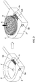
- the worm gear assembly 1 shown in Figure 1 includes a housing 2, a worm 3, and a globoid worm gear 4.
- the housing 2 includes a recess 6 in which the globoid worm gear 4 is seated.
- the housing 2 also includes a mount (7, see Figure 2 ) to which the globoid worm gear 4 is rotationally mounted, for example a hole as illustrated, or alternatively a shaft.
- the housing 2 also includes mount portions 5a, 5b for rotationally mounting the worm 3 such that the worm 3 extends across one side of the recess 6.
- the worm 3 engages the globoid worm gear 4. Rotation of the worm 3 thereby drives rotation of the globoid worm gear 4.
- An axis of rotation of the worm 3 is perpendicular to an axis of rotation of the globoid worm gear 4.
- the worm 3 includes one or more helical gear teeth 8 on a circumferential surface.
- the globoid worm gear 4 includes a plurality of gear teeth 9 arranged to engage the helical gear teeth 8 of the worm 3.
- the mount (7, see Figure 2 ) for the globoid worm gear 4 and the mount portions 5a, 5b for the worm 3 are arranged such that the worm 3 engages the globoid worm gear 4 such that rotation of the worm 3 drives rotation of the globoid worm gear 4.
- the worm 3 is mounted to the housing 2, in particular via mount portions 5a, 5b, and then the globoid worm gear 4 is attached to the housing 2, in particular at the mount 7, by inserting the globoid worm gear 4 into the recess 6 in an axial direction of the globoid worm gear 4.
- the globoid worm gear 4 may be pressed into the recess 6.
- the recess 6 is preferably configured to closely surround the circumferential face of the globoid worm gear 4 with only a small spacing between the surface of the recess 6 and the gear teeth 9 of the globoid worm gear 4.
- the recess 6 is cylindrical with an opening at one end to accommodate the worm 3.
- the worm 3 may be rotationally mounted to the housing 2 at a single mount point, for example mount point 5a.
- the globoid worm gear 4 may comprise a spigot or shaft to engage the mount 7 in the form of a hole, as illustrated, or the mount 7 of the housing 2 may include a shaft or spigot for mounting the globoid worm gear 4.
- the housing 2 may comprise two parts that are assembled with the worm 3 in between to facilitate assembly of the housing 2 and the worm 3.
- the worm gear assembly 1 may include one or more bearings or bushings for the worm 3 and/or the globoid worm gear 4.
- the housing 2 and/or the worm 3 and/or a shaft or spigot of the globoid worm gear 4 may comprise a low friction or self-lubricating material, for example a polyamide such as Nylon, or a polyoxymethylene.
- the globoid worm gear 4 may be made of a self-lubricating material, for example a polyamide such as Nylon, or a polyoxymethylene.
- the globoid worm gear 4 is coupled to a further component, not illustrated, such that the further component is rotated by the globoid worm gear 4 when the worm 3 is rotated.
- the globoid worm gear 4 may be coupled to a windscreen wiper for actuating the windscreen wiper, or to a window lift system for opening and closing a window.
- the worm gear assembly 1 may be an automotive worm gear assembly.
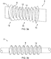
- Figure 3a shows a first example of the worm 3 of the worm gear assembly 1.
- the worm 3 is a globoid worm 3.
- the globoid worm 3 comprises one or more helical gear teeth 8 on a circumferential surface 12 of the globoid worm 3, for example one, two or three helical gear teeth 8.
- a depth of the helical gear teeth 8 of the globoid worm 3 varies along the length of the globoid worm 3.
- the depth 13 of the helical gear teeth 8 is greater at the ends 15 of the helical gear teeth 8 than in the centre 16.
- the helical gear teeth 8 conform to the circumference of the globoid worm gear 4 to increase contact surface area between the helical gear teeth 8 and the gear teeth 9 of the globoid worm gear 4. Additionally, the diameter of the shaft 14 of the globoid worm 3, from which the helical gear teeth 8 protrude, may be reduced in the centre 16 in the same manner, as illustrated.
- Figure 3b shows an alternative example of the worm 3 of the worm gear assembly 1.
- the worm 3 is a conventional worm 3.
- the conventional worm 3 comprises one or more helical gear teeth 8 on a circumferential surface 12 of the conventional worm 3, for example one, two or three helical gear teeth 8.
- a depth of the helical gear teeth 8 of the conventional worm 3 remains constant along the length of the conventional worm 3.
- a globoid worm 3 (see Figure 3a ) or a conventional worm 3 (see Figure 3b ) may be used in the worm gear assembly 1 illustrated in Figure 1 .
- the worm 3 is a conventional worm 3, as illustrated in Figure 3b , as a conventional worm 3 is easier to manufacture and less expensive than a globoid worm, as illustrated in Figure 3a .
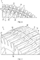
- Figures 4 to 7 illustrate different examples of the globoid worm gear 4 for the worm gear assembly 1 described above.
- the globoid worm gear 4 comprises first and second surfaces 17, 18, in particular a front surface 17 and a back surface 18.
- the globoid worm gear 4 also includes a circumferential surface 10 that extends between the first and second surfaces 17, 18.
- the globoid worm gear 4 comprises a plurality of gear teeth 9 spaced about the circumferential surface 10 of the globoid worm gear 4. Spaces 11 are arranged between the gear teeth 9.
- each space 11 extends to both the front and back surfaces 17, 18 of the globoid worm gear 4 such that the spaces 11 open into the front and back surfaces 17, 18.
- This allows the globoid worm gear 4 to be engaged with the worm 3 by moving the globoid worm gear 4 in an axial direction, as illustrated in Figure 2 .
- the helical gear tooth 8 of the worm 3 can enter the spaces 11 between the gear teeth 9 as the globoid worm gear 4 is moved axially.
- a further advantage of the spaces 11 opening into the front and back surfaces 17, 18 is that the globoid worm gear 4 can be more simply moulded, in particular injection moulded, because fewer sliding cores are required to form the gear teeth 9 about the circumferential surface 10.
- each gear tooth 9 has a top surface 19 that includes a recess 20.
- the recesses 20 are arranged centrally in the gear teeth 9 and configured to align with, and accommodate, the shaft 14 of the worm 3 (see Figures 3a and 3b ). This allows a closer spacing between the worm 3 and the globoid worm gear 4, increasing the contact surface area between the helical gear tooth 8 of the worm 3 and the gear teeth 9 of the globoid worm gear 4.
- each gear tooth 9 preferably a tooth width 21 of each gear tooth 9 (i.e. the thickness of the tooth 9 in a circumferential direction) is thinner in the centre than towards the opposing surfaces 17, 18 of the globoid worm gear 4.
- the side surfaces 22 of each gear tooth 9 are concave. Such a configuration improves contact surface area between the helical gear tooth 8 of the worm 3 and the gear teeth 9 of the globoid worm gear 4.
- the globoid worm gear 4 includes a flange 23 on the back face 18.
- the flange 23 may be an integrally moulded part of the globoid worm gear 4, or attached to the globoid worm gear 4.
- the spaces 11 between the gear teeth 9 do not open onto the back face 18 of the globoid worm gear 4.
- the spaces 11 between the gear teeth 9 do open onto the front face 17 of the globoid worm gear 4, allowing axial assembly of the globoid worm gear 4 into the housing 2 via the front face 17, as described with reference to Figure 2 .
- the globoid worm gear 4 is a semi-globoid worm gear.
- the root surfaces 24 in the spaces 11 between gear teeth 9 are curved upwards (i.e. curved in a radially outward direction) towards the flange 23.
- the flange 23 and the curved root surfaces 24 increase the strength of the gear teeth 9.
- gear teeth 9 have the recesses 20 and concave side surfaces 22 described with reference to Figure 4 .
- each of these features is optional in combination with the flange 23 and curved root surfaces 24.
- a front edge 27 of the globoid worm gear 4 has a chamfer 26.
- a front end 25 of each gear tooth 9 comprise a chamfer 26 that tapers towards the front surface 17 of the globoid worm gear 4.
- the edges of the spaces 11 at the front surface 17 each comprise a chamfer 26 that tapers towards the front surface 17 of the globoid worm gear 4. The chamfer 26 makes it easier for the globoid worm gear 4 to engage the worm 3 during assembly of the gear assembly 1 as illustrated in Figure 2 .
- the chamfer 26 guides the helical gear tooth 8 of the worm 3 into the spaces 11 between the gear teeth 9, and may additionally cause deformation of the gear teeth 9 as the globoid worm gear 4 is pressed into the housing 2 as shown in Figure 2 , to allow the helical gear tooth 8 to enter the space 11.
- the gear teeth 9 (in particular the side surfaces 22), spaces 11, and front edge 27 of the globoid worm gear 4 are configured such that the helical gear tooth 8 of the worm 3 must be pressed into the spaces 11 to overcome interference between the helical gear tooth 9 and the gear teeth 9 before clicking into the spaces between the concave side surfaces 22 of the gear teeth 9.
- the gear assembly 1 of Figure 1 can be assembled by pressing the globoid worm gear 4 into the housing 2 to engage the worm 3, and the interference prevents the globoid worm gear 4 from falling out of position during further assembly operations, which may include inverting the gear assembly 1 illustrated in Figure 1 .
- the interference also provides for a close fit between the gear teeth 9 of the globoid worm gear 4 and the helical gear tooth 8 of the worm 3, reducing backlash and increasing contact surface area during use.
- gear teeth 9 have the recesses 20 and concave side surfaces 22 described with reference to Figure 4 .
- each of these features is optional in combination with the chamfer 26.
- the globoid worm gear 4 described with refence to Figure 5 may additionally include the chamfer 26 illustrated in Figure 6 .
- each gear tooth 9 comprises a first portion 32 adjacent the front face 17 and a second portion 28 adjacent the back face 18.
- the second portion 28 has a greater diameter than the first portion 32, resulting in a step, or preferably a ramp 29, between the first and second portions 32, 28.
- the lower diameter of the first portions 32 permits axial assembly of the globoid worm gear 4 with the worm 3 and housing 2 in the manner described with reference to Figure 2 .
- the lower diameter of the first portion 32 reduces or eliminates interference between the helical gear tooth 8 of the worm 3 and the gear teeth 9 of the globoid worm gear 4 that might otherwise prevent the helical gear tooth 8 entering the spaces 11 to engage, and also allows the shaft 14 of the worm 3 to move into position.
- the second portions 28 provide greater contact surface area between the helical gear tooth 8 of the worm 3 and the gear teeth 9 of the globoid worm gear 4. This increases contact surface area and improves torque transmission, and also increases the rigidity of the gear teeth 9.
- the first portions 32 may be at the diameter of the recesses 20 described with reference to Figure 4 so that there is no need for the recesses 20.
- the globoid worm gear 4 is a semi-globoid worm gear.
- the gear teeth 9 of the example of Figure 7 may additionally include recesses 20 such as those described with reference to Figure 4 .
- the gear teeth 9 may optionally include the concave side surfaces 22 described with reference to Figure 4 .
- the globoid worm gear 4 may include a flange 23 and/or curved root surface 24 as described with reference to Figure 5 , and/or the chamfer 26 described with reference to Figure 6 .
- Figure 8 illustrates an example globoid worm gear 4 and indicates the contact points of the helical gear tooth 8 of the worm 3 of the gear assembly illustrated in Figure 1 .
- the globoid worm gear 4 includes gear teeth 9 that include concave side surfaces 22 and a chamfer 26 on the front edge 27, as described with reference to Figures 4 and 6 .
- gear teeth 9 are engaged simultaneously, and at maximum engagement (gear tooth 9a as indicated) approximately the entire concave part of the side surface 22 is engaged. Therefore, the concave side surfaces 22 of the gear teeth 9 increase contact surface area between the helical gear tooth 8 of the worm 3 and the gear teeth 9 of the globoid worm gear 4, which improves torque transfer.
- Figure 9 illustrates the gear teeth section subjected to shear stress 30 in the gear teeth 9 of the globoid worm gear 4 of Figure 5 .
- Figure 10 illustrates the gear teeth section subjected to shear stress 30 in the gear teeth 9 of the globoid worm gear 4 of Figure 6 .
- the shear stress is distributed over a larger surface area 30 in the globoid worm gear 4 of Figure 6 than for the semi-globoid worm gear 4 of Figure 5 .
- the surface area 30 over which the shear force is distributed in increased, reducing the maximum shear stress on each gear tooth 9 and prolonging the life of the globoid worm gear 4.
- the gear teeth 9 of the globoid worm gear 4 are helical, although the helix angle is very low.
- a globoid worm gear 4 for engagement with a globoid worm 3 in a worm gear assembly 1.
- the globoid worm gear 4 has first and second side surfaces 17, 18, a circumferential surface 10, and an axis of rotation.
- the globoid worm gear 4 also includes a plurality of gear teeth 9 spaced about the circumferential surface 10 with spaces 11 arranged between adjacent gear teeth 9.
- the plurality of gear teeth 9 are configured to engage the globoid worm 3.
- the plurality of gear teeth 9 are configured such that the spaces 11 between adjacent gear teeth 9 open into the first side surface 17.
- the worm gear assembly 1 includes a housing 2, a globoid worm 3, and the globoid worm gear 4.
- the globoid worm gear 4 and the globoid worm 3 are mounted to the housing 2 for rotation about perpendicular axes of rotation and such that the globoid worm 3 engages the gear teeth 9 of the globoid worm gear 4.
- the method includes first mounting the worm 3 to the housing 2 and then mounting the globoid worm gear 4 to the housing 2 by inserting the globoid worm gear 4 into the recess 6 in an axial direction of the globoid worm gear 4. As the globoid worm gear 4 is inserted into the housing 2 the gear teeth 9 of the globoid worm gear 4 engage the gear tooth or teeth of the worm 3.
Landscapes
- Engineering & Computer Science (AREA)
- General Engineering & Computer Science (AREA)
- Mechanical Engineering (AREA)
- Gears, Cams (AREA)
- Gear Transmission (AREA)
- Power Steering Mechanism (AREA)
Abstract
Description
- The invention relates to a globoid worm gear for engagement with a worm in a worm gear assembly, and to a gear assembly including a globoid worm gear and a worm.
- A globoid worm gear assembly includes a worm and a globoid worm gear that is rotated by the worm. The worm includes one or more helical gear teeth that engage gear teeth of the globoid worm gear to transfer rotation. The worm and the globoid worm gear rotate about perpendicular axes of rotation.
- A globoid worm gear is shaped to increase the surface area of its gear teeth compared to a conventional worm gear. This provides for decreased contact pressure and an increased number of gear teeth in engagement, which reduces gear wear and increases transmissible torque.
- Assembly of such a globoid worm gear assembly is limited because it is not possible for the worm to be assembled on a housing before the globoid worm gear, and for the globoid worm gear to be engaged with the worm by moving it in an axial direction into the housing due to interference between the worm and the globoid worm gear.
- According to the present invention, there is provided a globoid worm gear for engagement with a worm in a worm gear assembly. The globoid worm gear comprises first and second side surfaces, a circumferential surface, and an axis of rotation. The globoid worm gear also comprises a plurality of gear teeth spaced about the circumferential surface with spaces arranged between adjacent gear teeth, the plurality of gear teeth being configured to engage the worm. The plurality of gear teeth are configured such that the spaces between adjacent gear teeth open into the first side surface. Such a globoid worm gear may be termed an open or semi-open globoid worm gear.
- In examples, edges of the plurality of gear teeth at the first side surface each comprise a chamfer. Additionally or alternatively, edges of the spaces at the first side surface each comprise a chamfer. In particular, an edge of the first side surface may comprise a chamfer, the edge incorporating the edges of the plurality of gear teeth at the first side surface, and the edges of the spaces at the first side surface.
- There is also provided a worm gear assembly comprising the globoid worm gear described above, a worm, and a housing comprising a recess shaped to receive the globoid worm gear. The globoid worm gear and the worm are mounted to the housing for rotation about perpendicular axes of rotation and such that the worm engages the gear teeth of the globoid worm gear.
- There is also provided a method of assembling the worm gear assembly. The method comprises mounting the worm to the housing and then mounting the globoid worm gear to the housing by inserting the globoid worm gear into the recess in an axial direction of the globoid worm gear. In particular, the method comprises inserting an open or semi-open globoid worm gear into the recess in an axial direction of the globoid worm gear.
- Example embodiment(s) of the invention are illustrated in the accompanying drawings, in which:
-
Figure 1 illustrates a perspective view of a worm gear assembly; -
Figure 2 illustrates perspective view the worm gear assembly ofFigure 1 being assembled; -
Figure 3a illustrates a globoid worm of the worm gear assembly ofFigure 1 ; -
Figure 3b illustrates a conventional worm of the worm gear assembly ofFigure 1 ; -
Figure 4 illustrates a first example globoid worm gear of the worm gear assembly ofFigure 1 ; -
Figure 5 illustrates a second example globoid worm gear of the worm gear assembly ofFigure 1 ; -
Figure 6 illustrates a third example globoid worm gear of the worm gear assembly ofFigure 1 ; -
Figure 7 illustrates a fourth example globoid worm gear of the worm gear assembly ofFigure 1 ; -
Figure 8 illustrates an example globoid worm gear of the worm gear assembly ofFigure 1 , showing contact surfaces with the globoid worm; -
Figure 9 illustrates the gear tooth shear stress distribution of an example globoid worm gear of the worm gear assembly ofFigure 1 ; and -
Figure 10 illustrates the gear tooth shear stress distribution of another example globoid worm gear of the worm gear assembly ofFigure 1 . - The illustrated example embodiments relate to a globoid worm gear for engagement with a worm in a worm gear assembly.
- The worm gear assembly 1 shown in
Figure 1 includes a housing 2, aworm 3, and agloboid worm gear 4. The housing 2 includes arecess 6 in which thegloboid worm gear 4 is seated. The housing 2 also includes a mount (7, seeFigure 2 ) to which thegloboid worm gear 4 is rotationally mounted, for example a hole as illustrated, or alternatively a shaft. The housing 2 also includesmount portions worm 3 such that theworm 3 extends across one side of therecess 6. In the assembled state shown inFigure 1 , theworm 3 engages thegloboid worm gear 4. Rotation of theworm 3 thereby drives rotation of thegloboid worm gear 4. An axis of rotation of theworm 3 is perpendicular to an axis of rotation of thegloboid worm gear 4. - The
worm 3 includes one or morehelical gear teeth 8 on a circumferential surface. Thegloboid worm gear 4 includes a plurality ofgear teeth 9 arranged to engage thehelical gear teeth 8 of theworm 3. In particular, as shown inFigure 1 , the mount (7, seeFigure 2 ) for thegloboid worm gear 4 and themount portions worm 3 are arranged such that theworm 3 engages thegloboid worm gear 4 such that rotation of theworm 3 drives rotation of thegloboid worm gear 4. - As shown in
Figure 2 , in a preferred method of assembling the worm gear assembly 1 theworm 3 is mounted to the housing 2, in particular viamount portions globoid worm gear 4 is attached to the housing 2, in particular at themount 7, by inserting thegloboid worm gear 4 into therecess 6 in an axial direction of thegloboid worm gear 4. Thegloboid worm gear 4 may be pressed into therecess 6. - As shown, the
recess 6 is preferably configured to closely surround the circumferential face of thegloboid worm gear 4 with only a small spacing between the surface of therecess 6 and thegear teeth 9 of thegloboid worm gear 4. In particular, therecess 6 is cylindrical with an opening at one end to accommodate theworm 3. - In alternative examples, the
worm 3 may be rotationally mounted to the housing 2 at a single mount point, forexample mount point 5a. Thegloboid worm gear 4 may comprise a spigot or shaft to engage themount 7 in the form of a hole, as illustrated, or themount 7 of the housing 2 may include a shaft or spigot for mounting thegloboid worm gear 4. The housing 2 may comprise two parts that are assembled with theworm 3 in between to facilitate assembly of the housing 2 and theworm 3. - The worm gear assembly 1 may include one or more bearings or bushings for the
worm 3 and/or thegloboid worm gear 4. Alternatively, the housing 2 and/or theworm 3 and/or a shaft or spigot of thegloboid worm gear 4 may comprise a low friction or self-lubricating material, for example a polyamide such as Nylon, or a polyoxymethylene. In some examples, thegloboid worm gear 4 may be made of a self-lubricating material, for example a polyamide such as Nylon, or a polyoxymethylene. - In a final configuration the
globoid worm gear 4 is coupled to a further component, not illustrated, such that the further component is rotated by thegloboid worm gear 4 when theworm 3 is rotated. For example, thegloboid worm gear 4 may be coupled to a windscreen wiper for actuating the windscreen wiper, or to a window lift system for opening and closing a window. Accordingly, the worm gear assembly 1 may be an automotive worm gear assembly. -
Figure 3a shows a first example of theworm 3 of the worm gear assembly 1. In this example, theworm 3 is agloboid worm 3. Thegloboid worm 3 comprises one or morehelical gear teeth 8 on acircumferential surface 12 of thegloboid worm 3, for example one, two or threehelical gear teeth 8. In contrast to a conventional worm (seeFigure 3b ), a depth of thehelical gear teeth 8 of thegloboid worm 3 varies along the length of thegloboid worm 3. In particular, thedepth 13 of thehelical gear teeth 8 is greater at theends 15 of thehelical gear teeth 8 than in thecentre 16. In this way, thehelical gear teeth 8 conform to the circumference of thegloboid worm gear 4 to increase contact surface area between thehelical gear teeth 8 and thegear teeth 9 of thegloboid worm gear 4. Additionally, the diameter of theshaft 14 of thegloboid worm 3, from which thehelical gear teeth 8 protrude, may be reduced in thecentre 16 in the same manner, as illustrated. -
Figure 3b shows an alternative example of theworm 3 of the worm gear assembly 1. In this example, theworm 3 is aconventional worm 3. Theconventional worm 3 comprises one or morehelical gear teeth 8 on acircumferential surface 12 of theconventional worm 3, for example one, two or threehelical gear teeth 8. In contrast to the globoid worm (seeFigure 3a ), a depth of thehelical gear teeth 8 of theconventional worm 3 remains constant along the length of theconventional worm 3. - It will be appreciated that either a globoid worm 3 (see
Figure 3a ) or a conventional worm 3 (seeFigure 3b ) may be used in the worm gear assembly 1 illustrated inFigure 1 . Preferably, theworm 3 is aconventional worm 3, as illustrated inFigure 3b , as aconventional worm 3 is easier to manufacture and less expensive than a globoid worm, as illustrated inFigure 3a . -
Figures 4 to 7 illustrate different examples of thegloboid worm gear 4 for the worm gear assembly 1 described above. In each of the examples ofFigures 4 to 7 , thegloboid worm gear 4 comprises first andsecond surfaces front surface 17 and aback surface 18. Thegloboid worm gear 4 also includes acircumferential surface 10 that extends between the first andsecond surfaces globoid worm gear 4 comprises a plurality ofgear teeth 9 spaced about thecircumferential surface 10 of thegloboid worm gear 4.Spaces 11 are arranged between thegear teeth 9. - In the example of
Figure 4 , eachspace 11 extends to both the front and back surfaces 17, 18 of thegloboid worm gear 4 such that thespaces 11 open into the front and back surfaces 17, 18. This allows thegloboid worm gear 4 to be engaged with theworm 3 by moving thegloboid worm gear 4 in an axial direction, as illustrated inFigure 2 . In particular, as thespaces 11 open into the front and back surfaces 17, 18, thehelical gear tooth 8 of theworm 3 can enter thespaces 11 between thegear teeth 9 as thegloboid worm gear 4 is moved axially. - A further advantage of the
spaces 11 opening into the front and back surfaces 17, 18 is that thegloboid worm gear 4 can be more simply moulded, in particular injection moulded, because fewer sliding cores are required to form thegear teeth 9 about thecircumferential surface 10. - As also illustrated in
Figure 4 , eachgear tooth 9 has atop surface 19 that includes arecess 20. Therecesses 20 are arranged centrally in thegear teeth 9 and configured to align with, and accommodate, theshaft 14 of the worm 3 (seeFigures 3a and 3b ). This allows a closer spacing between theworm 3 and thegloboid worm gear 4, increasing the contact surface area between thehelical gear tooth 8 of theworm 3 and thegear teeth 9 of thegloboid worm gear 4. - As also illustrated in
Figure 4 , preferably atooth width 21 of each gear tooth 9 (i.e. the thickness of thetooth 9 in a circumferential direction) is thinner in the centre than towards the opposingsurfaces globoid worm gear 4. In particular, the side surfaces 22 of eachgear tooth 9 are concave. Such a configuration improves contact surface area between thehelical gear tooth 8 of theworm 3 and thegear teeth 9 of thegloboid worm gear 4. - In the example of
Figure 5 thegloboid worm gear 4 includes aflange 23 on theback face 18. Theflange 23 may be an integrally moulded part of thegloboid worm gear 4, or attached to thegloboid worm gear 4. As such, thespaces 11 between thegear teeth 9 do not open onto theback face 18 of thegloboid worm gear 4. Thespaces 11 between thegear teeth 9 do open onto thefront face 17 of thegloboid worm gear 4, allowing axial assembly of thegloboid worm gear 4 into the housing 2 via thefront face 17, as described with reference toFigure 2 . - In the example of
Figure 5 , where thespaces 11 are closed by theflange 23 on one side, thegloboid worm gear 4 is a semi-globoid worm gear. - As illustrated in
Figure 5 , the root surfaces 24 in thespaces 11 betweengear teeth 9 are curved upwards (i.e. curved in a radially outward direction) towards theflange 23. Theflange 23 and the curved root surfaces 24 increase the strength of thegear teeth 9. - In the example of
Figure 5 thegear teeth 9 have therecesses 20 and concave side surfaces 22 described with reference toFigure 4 . However, it will be appreciated that each of these features is optional in combination with theflange 23 and curved root surfaces 24. - In the example of
Figure 6 , afront edge 27 of thegloboid worm gear 4 has achamfer 26. In particular, afront end 25 of eachgear tooth 9 comprise achamfer 26 that tapers towards thefront surface 17 of thegloboid worm gear 4. Additionally or alternatively, the edges of thespaces 11 at thefront surface 17 each comprise achamfer 26 that tapers towards thefront surface 17 of thegloboid worm gear 4. Thechamfer 26 makes it easier for thegloboid worm gear 4 to engage theworm 3 during assembly of the gear assembly 1 as illustrated inFigure 2 . In particular, thechamfer 26 guides thehelical gear tooth 8 of theworm 3 into thespaces 11 between thegear teeth 9, and may additionally cause deformation of thegear teeth 9 as thegloboid worm gear 4 is pressed into the housing 2 as shown inFigure 2 , to allow thehelical gear tooth 8 to enter thespace 11. - Preferably, the gear teeth 9 (in particular the side surfaces 22),
spaces 11, andfront edge 27 of thegloboid worm gear 4 are configured such that thehelical gear tooth 8 of theworm 3 must be pressed into thespaces 11 to overcome interference between thehelical gear tooth 9 and thegear teeth 9 before clicking into the spaces between the concave side surfaces 22 of thegear teeth 9. In this way, the gear assembly 1 ofFigure 1 can be assembled by pressing thegloboid worm gear 4 into the housing 2 to engage theworm 3, and the interference prevents thegloboid worm gear 4 from falling out of position during further assembly operations, which may include inverting the gear assembly 1 illustrated inFigure 1 . The interference also provides for a close fit between thegear teeth 9 of thegloboid worm gear 4 and thehelical gear tooth 8 of theworm 3, reducing backlash and increasing contact surface area during use. - In the example of
Figure 6 thegear teeth 9 have therecesses 20 and concave side surfaces 22 described with reference toFigure 4 . However, it will be appreciated that each of these features is optional in combination with thechamfer 26. In addition, thegloboid worm gear 4 described with refence toFigure 5 may additionally include thechamfer 26 illustrated inFigure 6 . - In the example of
Figure 7 , thetop surface 19 eachgear tooth 9 comprises afirst portion 32 adjacent thefront face 17 and asecond portion 28 adjacent theback face 18. Thesecond portion 28 has a greater diameter than thefirst portion 32, resulting in a step, or preferably aramp 29, between the first andsecond portions - The lower diameter of the
first portions 32 permits axial assembly of thegloboid worm gear 4 with theworm 3 and housing 2 in the manner described with reference toFigure 2 . In particular, the lower diameter of thefirst portion 32 reduces or eliminates interference between thehelical gear tooth 8 of theworm 3 and thegear teeth 9 of thegloboid worm gear 4 that might otherwise prevent thehelical gear tooth 8 entering thespaces 11 to engage, and also allows theshaft 14 of theworm 3 to move into position. Thesecond portions 28 provide greater contact surface area between thehelical gear tooth 8 of theworm 3 and thegear teeth 9 of thegloboid worm gear 4. This increases contact surface area and improves torque transmission, and also increases the rigidity of thegear teeth 9. - In some examples, the
first portions 32 may be at the diameter of therecesses 20 described with reference toFigure 4 so that there is no need for therecesses 20. In such an example, thegloboid worm gear 4 is a semi-globoid worm gear. Alternatively, thegear teeth 9 of the example ofFigure 7 may additionally includerecesses 20 such as those described with reference toFigure 4 . - In the example of
Figure 7 thegear teeth 9 may optionally include the concave side surfaces 22 described with reference toFigure 4 . Additionally or alternatively, thegloboid worm gear 4 may include aflange 23 and/orcurved root surface 24 as described with reference toFigure 5 , and/or thechamfer 26 described with reference toFigure 6 . -
Figure 8 illustrates an examplegloboid worm gear 4 and indicates the contact points of thehelical gear tooth 8 of theworm 3 of the gear assembly illustrated inFigure 1 . As shown, thegloboid worm gear 4 includesgear teeth 9 that include concave side surfaces 22 and achamfer 26 on thefront edge 27, as described with reference toFigures 4 and6 . - As shown in
Figure 8 , the concave side surfaces 22 are engaged by thehelical gear tooth 8 across the concave parts of the side surfaces 22.Regions 31 of thegear teeth 9, as illustrated inFigure 8 , are engaged by thehelical gear tooth 8 of theworm 3. - In this example, four
gear teeth 9 are engaged simultaneously, and at maximum engagement (gear tooth 9a as indicated) approximately the entire concave part of theside surface 22 is engaged. Therefore, the concave side surfaces 22 of thegear teeth 9 increase contact surface area between thehelical gear tooth 8 of theworm 3 and thegear teeth 9 of thegloboid worm gear 4, which improves torque transfer. -
Figure 9 illustrates the gear teeth section subjected toshear stress 30 in thegear teeth 9 of thegloboid worm gear 4 ofFigure 5 .Figure 10 illustrates the gear teeth section subjected toshear stress 30 in thegear teeth 9 of thegloboid worm gear 4 ofFigure 6 . - As illustrated, the shear stress is distributed over a
larger surface area 30 in thegloboid worm gear 4 ofFigure 6 than for thesemi-globoid worm gear 4 ofFigure 5 . Thesurface area 30 over which the shear force is distributed in increased, reducing the maximum shear stress on eachgear tooth 9 and prolonging the life of thegloboid worm gear 4. - Preferably, the
gear teeth 9 of thegloboid worm gear 4 are helical, although the helix angle is very low. - In summary, there is provided a
globoid worm gear 4 for engagement with agloboid worm 3 in a worm gear assembly 1. Thegloboid worm gear 4 has first and second side surfaces 17, 18, acircumferential surface 10, and an axis of rotation. Thegloboid worm gear 4 also includes a plurality ofgear teeth 9 spaced about thecircumferential surface 10 withspaces 11 arranged betweenadjacent gear teeth 9. The plurality ofgear teeth 9 are configured to engage thegloboid worm 3. The plurality ofgear teeth 9 are configured such that thespaces 11 betweenadjacent gear teeth 9 open into thefirst side surface 17. - There is also provided a worm gear assembly that includes the
globoid worm gear 4. The worm gear assembly 1 includes a housing 2, agloboid worm 3, and thegloboid worm gear 4. Thegloboid worm gear 4 and thegloboid worm 3 are mounted to the housing 2 for rotation about perpendicular axes of rotation and such that thegloboid worm 3 engages thegear teeth 9 of thegloboid worm gear 4. - There is also provided a method of assembling the worm gear assembly 1 described above. The method includes first mounting the
worm 3 to the housing 2 and then mounting thegloboid worm gear 4 to the housing 2 by inserting thegloboid worm gear 4 into therecess 6 in an axial direction of thegloboid worm gear 4. As thegloboid worm gear 4 is inserted into the housing 2 thegear teeth 9 of thegloboid worm gear 4 engage the gear tooth or teeth of theworm 3.
Claims (11)
- A globoid worm gear (4) for engagement with a worm (3) in a worm gear assembly (1), the globoid worm gear (4) comprising:first and second side surfaces (17, 18), a circumferential surface (10), and an axis of rotation; anda plurality of gear teeth (9) spaced about the circumferential surface (10) with spaces (11) arranged between adjacent gear teeth (9), the plurality of gear teeth (9) being configured to engage the worm (3);wherein the plurality of gear teeth (9) are configured such that the spaces (11) between adjacent gear teeth (9) open into the first side surface (17).
- The globoid worm gear (4) of claim 1, wherein edges of the plurality of gear teeth (9) at the first side surface (17) each comprise a chamfer (26).
- The globoid worm gear (4) of claim 1 or claim 2, wherein edges of the spaces (11) at the first side surface (17) each comprise a chamfer (26).
- The globoid worm gear (4) of any preceding claim, wherein each of the plurality of gear teeth (9) comprises concave side surfaces (22) to engage the worm (3).
- The globoid worm gear (4) of any preceding claim, wherein the gear teeth (9) are configured such that the spaces (11) between adjacent gear teeth (9) extend the second side surface (18).
- The globoid worm gear (4) of any of claims 1 to 4, where the gear teeth (9) are configured such that the spaces (11) between adjacent gear teeth (9) extend to only the first side surface (17), the second side surface (18) comprising a flange (23) that closes the ends of the spaces (11) between adjacent gear teeth (9).
- The globoid worm gear (4) of claim 6, wherein each space (11) between adjacent gear teeth (9) comprises a root surface (24) that is curved in a radially outward direction of the globoid worm gear (4) towards the flange (23).
- The globoid worm gear (4) of claim 6 or claim 7, wherein each of the plurality of gear teeth (9) comprises a top surface (19), wherein each top surface (19) comprises a first portion (32) adjacent to the first side surface (17) and a second portion (28) adjacent to the second side surface (18), and wherein a radius of the second portion (28) from the axis of rotation is greater than a radius of the first portion (32) from the axis of rotation.
- The globoid worm gear (4) of any preceding claim, wherein the globoid worm gear (4) is configured to engage with a conventional worm or a globoid worm.
- A worm gear assembly (1) comprising the globoid worm gear (4) of any of claims 1 to 9, a worm (3), and a housing (2) comprising a recess (6) shaped to receive the globoid worm gear (4), and wherein the globoid worm gear (4) and the worm (3) are mounted to the housing (2) for rotation about perpendicular axes of rotation and such that the worm (3) engages gear teeth (9) of the globoid worm gear (4).
- A method of assembling the worm gear assembly (1) of claim 10, comprising mounting the worm (3) to the housing (2) and then mounting the globoid worm gear (4) to the housing (2) by inserting the globoid worm gear (4) into the recess (6) in an axial direction of the globoid worm gear (4).
Priority Applications (3)
| Application Number | Priority Date | Filing Date | Title |
|---|---|---|---|
| CN202180017381.2A CN115176098A (en) | 2020-03-26 | 2021-03-16 | Spherical worm wheel |
| PCT/US2021/022471 WO2021194794A1 (en) | 2020-03-26 | 2021-03-16 | Globoid worm gear |
| US17/913,746 US12110957B2 (en) | 2020-03-26 | 2021-03-16 | Globoid worm gear |
Applications Claiming Priority (1)
| Application Number | Priority Date | Filing Date | Title |
|---|---|---|---|
| EP20165830 | 2020-03-26 |
Publications (1)
| Publication Number | Publication Date |
|---|---|
| EP3885612A1 true EP3885612A1 (en) | 2021-09-29 |
Family
ID=70049836
Family Applications (1)
| Application Number | Title | Priority Date | Filing Date |
|---|---|---|---|
| EP21160313.9A Pending EP3885612A1 (en) | 2020-03-26 | 2021-03-02 | Globoid worm gear |
Country Status (4)
| Country | Link |
|---|---|
| US (1) | US12110957B2 (en) |
| EP (1) | EP3885612A1 (en) |
| CN (1) | CN115176098A (en) |
| WO (1) | WO2021194794A1 (en) |
Citations (7)
| Publication number | Priority date | Publication date | Assignee | Title |
|---|---|---|---|---|
| US2448187A (en) * | 1947-02-10 | 1948-08-31 | Connecticut Variable Gear Corp | Worm and wheel unidirectional transmission gearing |
| DE1027032B (en) * | 1952-12-18 | 1958-03-27 | Asea Ab | Worm gear |
| JP2008055649A (en) * | 2006-08-29 | 2008-03-13 | Aisin Seiki Co Ltd | Worm wheel mold and molding method |
| DE102011050261A1 (en) * | 2011-05-11 | 2012-11-15 | Robert Bosch, spol. sr. o. | INJECTION MOLDING DEVICE FOR GLOBOIDIC TOOTHING AND METHOD FOR PRODUCING GLOBOIDIC TOOTHING |
| DE102012023462A1 (en) * | 2012-11-30 | 2014-06-05 | Volkswagen Aktiengesellschaft | Worm gear for motor vehicle steering system, has a worm wheel having several circumferentially spaced teeth arranged in transverse direction of wheel in only one direction to outer side of worm gear such that tooth height is increased |
| DE102014104284A1 (en) * | 2014-03-27 | 2015-10-01 | Robert Bosch Automotive Steering Gmbh | GEAR |
| DE102016222115A1 (en) * | 2016-11-10 | 2018-05-17 | Robert Bosch Gmbh | Spur gear for a worm gear, use of the spur gear and injection molding tool for producing the spur gear |
Family Cites Families (3)
| Publication number | Priority date | Publication date | Assignee | Title |
|---|---|---|---|---|
| US3516298A (en) * | 1968-08-22 | 1970-06-23 | Gewerk Eisenhuette Westfalia | Worm gearings |
| JPS6425551U (en) * | 1987-08-05 | 1989-02-13 | ||
| JP4052592B2 (en) * | 2004-04-22 | 2008-02-27 | 本田技研工業株式会社 | Worm gear mechanism and electric power steering device equipped with the worm gear mechanism |
-
2021
- 2021-03-02 EP EP21160313.9A patent/EP3885612A1/en active Pending
- 2021-03-16 US US17/913,746 patent/US12110957B2/en active Active
- 2021-03-16 CN CN202180017381.2A patent/CN115176098A/en active Pending
- 2021-03-16 WO PCT/US2021/022471 patent/WO2021194794A1/en not_active Ceased
Patent Citations (7)
| Publication number | Priority date | Publication date | Assignee | Title |
|---|---|---|---|---|
| US2448187A (en) * | 1947-02-10 | 1948-08-31 | Connecticut Variable Gear Corp | Worm and wheel unidirectional transmission gearing |
| DE1027032B (en) * | 1952-12-18 | 1958-03-27 | Asea Ab | Worm gear |
| JP2008055649A (en) * | 2006-08-29 | 2008-03-13 | Aisin Seiki Co Ltd | Worm wheel mold and molding method |
| DE102011050261A1 (en) * | 2011-05-11 | 2012-11-15 | Robert Bosch, spol. sr. o. | INJECTION MOLDING DEVICE FOR GLOBOIDIC TOOTHING AND METHOD FOR PRODUCING GLOBOIDIC TOOTHING |
| DE102012023462A1 (en) * | 2012-11-30 | 2014-06-05 | Volkswagen Aktiengesellschaft | Worm gear for motor vehicle steering system, has a worm wheel having several circumferentially spaced teeth arranged in transverse direction of wheel in only one direction to outer side of worm gear such that tooth height is increased |
| DE102014104284A1 (en) * | 2014-03-27 | 2015-10-01 | Robert Bosch Automotive Steering Gmbh | GEAR |
| DE102016222115A1 (en) * | 2016-11-10 | 2018-05-17 | Robert Bosch Gmbh | Spur gear for a worm gear, use of the spur gear and injection molding tool for producing the spur gear |
Also Published As
| Publication number | Publication date |
|---|---|
| US12110957B2 (en) | 2024-10-08 |
| CN115176098A (en) | 2022-10-11 |
| US20230102311A1 (en) | 2023-03-30 |
| WO2021194794A1 (en) | 2021-09-30 |
Similar Documents
| Publication | Publication Date | Title |
|---|---|---|
| DE102011113437B4 (en) | Clutch and motor | |
| DE69728692T2 (en) | Geared motor, in particular for driving accessories in motor vehicles | |
| US20070261516A1 (en) | Harmonic gear drive | |
| US8286524B2 (en) | Motor assembly | |
| US7972078B2 (en) | Power transmission mechanism of shaft and hub | |
| EP3499070B1 (en) | Joint for torque transmission, and electric power steering device | |
| EP2360385A1 (en) | Low noise elektric brake actuator | |
| EP2103843A1 (en) | Motor with reduction gear | |
| CN1199269A (en) | Small motor with reduction gear | |
| EP0947718A2 (en) | Shaft to actuator hub adapter | |
| US6382384B2 (en) | Clutch having reduced noise level and motor including such clutch | |
| JP2004529821A (en) | Actuator used for vehicle steering system | |
| US20040253912A1 (en) | Double flank delash gear mechanism | |
| EP1653100A1 (en) | Power transmission mechanism of shaft and hub | |
| EP1555449B1 (en) | Torque transmission device from a motor to a compressor | |
| US6817962B2 (en) | Planetary gear mechanism | |
| US12110957B2 (en) | Globoid worm gear | |
| US5716279A (en) | Apparatus and method for coupling an output shaft of a motor to a secondary shaft | |
| CN1878937B (en) | Throttle valve device and motor used for same | |
| US6918853B2 (en) | Planetary gear mechanism | |
| JPH09166185A (en) | Small-sized reduction gear having two deceleration stage | |
| CN112780748A (en) | Coaxial gear device | |
| JP2006153135A (en) | Constant-speed joint, and machining method, assembling method, and its assembling tool | |
| EP2659152B1 (en) | Drive unit with bearing device and adjustment drive | |
| CN107498550B (en) | Transmission mechanism capable of automatically making close contact and robot |
Legal Events
| Date | Code | Title | Description |
|---|---|---|---|
| PUAI | Public reference made under article 153(3) epc to a published international application that has entered the european phase |
Free format text: ORIGINAL CODE: 0009012 |
|
| STAA | Information on the status of an ep patent application or granted ep patent |
Free format text: STATUS: THE APPLICATION HAS BEEN PUBLISHED |
|
| AK | Designated contracting states |
Kind code of ref document: A1 Designated state(s): AL AT BE BG CH CY CZ DE DK EE ES FI FR GB GR HR HU IE IS IT LI LT LU LV MC MK MT NL NO PL PT RO RS SE SI SK SM TR |
|
| STAA | Information on the status of an ep patent application or granted ep patent |
Free format text: STATUS: REQUEST FOR EXAMINATION WAS MADE |
|
| 17P | Request for examination filed |
Effective date: 20220328 |
|
| RBV | Designated contracting states (corrected) |
Designated state(s): AL AT BE BG CH CY CZ DE DK EE ES FI FR GB GR HR HU IE IS IT LI LT LU LV MC MK MT NL NO PL PT RO RS SE SI SK SM TR |
|
| STAA | Information on the status of an ep patent application or granted ep patent |
Free format text: STATUS: EXAMINATION IS IN PROGRESS |
|
| 17Q | First examination report despatched |
Effective date: 20230619 |