EP3885605A1 - Wear sleeve for a shock body - Google Patents
Wear sleeve for a shock body Download PDFInfo
- Publication number
- EP3885605A1 EP3885605A1 EP21165231.8A EP21165231A EP3885605A1 EP 3885605 A1 EP3885605 A1 EP 3885605A1 EP 21165231 A EP21165231 A EP 21165231A EP 3885605 A1 EP3885605 A1 EP 3885605A1
- Authority
- EP
- European Patent Office
- Prior art keywords
- wear sleeve
- shock
- spring
- shock body
- assembly
- Prior art date
- Legal status (The legal status is an assumption and is not a legal conclusion. Google has not performed a legal analysis and makes no representation as to the accuracy of the status listed.)
- Pending
Links
Images




Classifications
-
- B—PERFORMING OPERATIONS; TRANSPORTING
- B60—VEHICLES IN GENERAL
- B60G—VEHICLE SUSPENSION ARRANGEMENTS
- B60G15/00—Resilient suspensions characterised by arrangement, location or type of combined spring and vibration damper, e.g. telescopic type
- B60G15/02—Resilient suspensions characterised by arrangement, location or type of combined spring and vibration damper, e.g. telescopic type having mechanical spring
- B60G15/06—Resilient suspensions characterised by arrangement, location or type of combined spring and vibration damper, e.g. telescopic type having mechanical spring and fluid damper
- B60G15/062—Resilient suspensions characterised by arrangement, location or type of combined spring and vibration damper, e.g. telescopic type having mechanical spring and fluid damper the spring being arranged around the damper
- B60G15/063—Resilient suspensions characterised by arrangement, location or type of combined spring and vibration damper, e.g. telescopic type having mechanical spring and fluid damper the spring being arranged around the damper characterised by the mounting of the spring on the damper
-
- F—MECHANICAL ENGINEERING; LIGHTING; HEATING; WEAPONS; BLASTING
- F16—ENGINEERING ELEMENTS AND UNITS; GENERAL MEASURES FOR PRODUCING AND MAINTAINING EFFECTIVE FUNCTIONING OF MACHINES OR INSTALLATIONS; THERMAL INSULATION IN GENERAL
- F16F—SPRINGS; SHOCK-ABSORBERS; MEANS FOR DAMPING VIBRATION
- F16F9/00—Springs, vibration-dampers, shock-absorbers, or similarly-constructed movement-dampers using a fluid or the equivalent as damping medium
- F16F9/32—Details
- F16F9/3207—Constructional features
- F16F9/3235—Constructional features of cylinders
-
- B—PERFORMING OPERATIONS; TRANSPORTING
- B60—VEHICLES IN GENERAL
- B60G—VEHICLE SUSPENSION ARRANGEMENTS
- B60G15/00—Resilient suspensions characterised by arrangement, location or type of combined spring and vibration damper, e.g. telescopic type
- B60G15/02—Resilient suspensions characterised by arrangement, location or type of combined spring and vibration damper, e.g. telescopic type having mechanical spring
- B60G15/06—Resilient suspensions characterised by arrangement, location or type of combined spring and vibration damper, e.g. telescopic type having mechanical spring and fluid damper
- B60G15/062—Resilient suspensions characterised by arrangement, location or type of combined spring and vibration damper, e.g. telescopic type having mechanical spring and fluid damper the spring being arranged around the damper
- B60G15/065—Resilient suspensions characterised by arrangement, location or type of combined spring and vibration damper, e.g. telescopic type having mechanical spring and fluid damper the spring being arranged around the damper characterised by the use of a combination of springs
-
- F—MECHANICAL ENGINEERING; LIGHTING; HEATING; WEAPONS; BLASTING
- F16—ENGINEERING ELEMENTS AND UNITS; GENERAL MEASURES FOR PRODUCING AND MAINTAINING EFFECTIVE FUNCTIONING OF MACHINES OR INSTALLATIONS; THERMAL INSULATION IN GENERAL
- F16F—SPRINGS; SHOCK-ABSORBERS; MEANS FOR DAMPING VIBRATION
- F16F13/00—Units comprising springs of the non-fluid type as well as vibration-dampers, shock-absorbers, or fluid springs
- F16F13/005—Units comprising springs of the non-fluid type as well as vibration-dampers, shock-absorbers, or fluid springs comprising both a wound spring and a damper, e.g. a friction damper
- F16F13/007—Units comprising springs of the non-fluid type as well as vibration-dampers, shock-absorbers, or fluid springs comprising both a wound spring and a damper, e.g. a friction damper the damper being a fluid damper
-
- F—MECHANICAL ENGINEERING; LIGHTING; HEATING; WEAPONS; BLASTING
- F16—ENGINEERING ELEMENTS AND UNITS; GENERAL MEASURES FOR PRODUCING AND MAINTAINING EFFECTIVE FUNCTIONING OF MACHINES OR INSTALLATIONS; THERMAL INSULATION IN GENERAL
- F16F—SPRINGS; SHOCK-ABSORBERS; MEANS FOR DAMPING VIBRATION
- F16F3/00—Spring units consisting of several springs, e.g. for obtaining a desired spring characteristic
- F16F3/02—Spring units consisting of several springs, e.g. for obtaining a desired spring characteristic with springs made of steel or of other material having low internal friction
- F16F3/04—Spring units consisting of several springs, e.g. for obtaining a desired spring characteristic with springs made of steel or of other material having low internal friction composed only of wound springs
-
- F—MECHANICAL ENGINEERING; LIGHTING; HEATING; WEAPONS; BLASTING
- F16—ENGINEERING ELEMENTS AND UNITS; GENERAL MEASURES FOR PRODUCING AND MAINTAINING EFFECTIVE FUNCTIONING OF MACHINES OR INSTALLATIONS; THERMAL INSULATION IN GENERAL
- F16F—SPRINGS; SHOCK-ABSORBERS; MEANS FOR DAMPING VIBRATION
- F16F9/00—Springs, vibration-dampers, shock-absorbers, or similarly-constructed movement-dampers using a fluid or the equivalent as damping medium
- F16F9/32—Details
- F16F9/38—Covers for protection or appearance
-
- B—PERFORMING OPERATIONS; TRANSPORTING
- B60—VEHICLES IN GENERAL
- B60G—VEHICLE SUSPENSION ARRANGEMENTS
- B60G2202/00—Indexing codes relating to the type of spring, damper or actuator
- B60G2202/30—Spring/Damper and/or actuator Units
- B60G2202/31—Spring/Damper and/or actuator Units with the spring arranged around the damper, e.g. MacPherson strut
- B60G2202/312—The spring being a wound spring
-
- B—PERFORMING OPERATIONS; TRANSPORTING
- B60—VEHICLES IN GENERAL
- B60G—VEHICLE SUSPENSION ARRANGEMENTS
- B60G2204/00—Indexing codes related to suspensions per se or to auxiliary parts
- B60G2204/10—Mounting of suspension elements
- B60G2204/12—Mounting of springs or dampers
- B60G2204/124—Mounting of coil springs
- B60G2204/1242—Mounting of coil springs on a damper, e.g. MacPerson strut
-
- B—PERFORMING OPERATIONS; TRANSPORTING
- B60—VEHICLES IN GENERAL
- B60G—VEHICLE SUSPENSION ARRANGEMENTS
- B60G2204/00—Indexing codes related to suspensions per se or to auxiliary parts
- B60G2204/40—Auxiliary suspension parts; Adjustment of suspensions
- B60G2204/423—Rails, tubes, or the like, for guiding the movement of suspension elements
- B60G2204/4232—Sliding mounts
-
- B—PERFORMING OPERATIONS; TRANSPORTING
- B60—VEHICLES IN GENERAL
- B60G—VEHICLE SUSPENSION ARRANGEMENTS
- B60G2204/00—Indexing codes related to suspensions per se or to auxiliary parts
- B60G2204/40—Auxiliary suspension parts; Adjustment of suspensions
- B60G2204/43—Fittings, brackets or knuckles
- B60G2204/4308—Protecting guards, e.g. for rigid axle damage protection
-
- B—PERFORMING OPERATIONS; TRANSPORTING
- B60—VEHICLES IN GENERAL
- B60G—VEHICLE SUSPENSION ARRANGEMENTS
- B60G2206/00—Indexing codes related to the manufacturing of suspensions: constructional features, the materials used, procedures or tools
- B60G2206/01—Constructional features of suspension elements, e.g. arms, dampers, springs
- B60G2206/70—Materials used in suspensions
- B60G2206/71—Light weight materials
- B60G2206/7101—Fiber-reinforced plastics [FRP]
-
- B—PERFORMING OPERATIONS; TRANSPORTING
- B60—VEHICLES IN GENERAL
- B60G—VEHICLE SUSPENSION ARRANGEMENTS
- B60G2206/00—Indexing codes related to the manufacturing of suspensions: constructional features, the materials used, procedures or tools
- B60G2206/01—Constructional features of suspension elements, e.g. arms, dampers, springs
- B60G2206/70—Materials used in suspensions
- B60G2206/72—Steel
-
- B—PERFORMING OPERATIONS; TRANSPORTING
- B60—VEHICLES IN GENERAL
- B60G—VEHICLE SUSPENSION ARRANGEMENTS
- B60G2500/00—Indexing codes relating to the regulated action or device
- B60G2500/20—Spring action or springs
- B60G2500/22—Spring constant
-
- B—PERFORMING OPERATIONS; TRANSPORTING
- B60—VEHICLES IN GENERAL
- B60G—VEHICLE SUSPENSION ARRANGEMENTS
- B60G2800/00—Indexing codes relating to the type of movement or to the condition of the vehicle and to the end result to be achieved by the control action
- B60G2800/16—Running
- B60G2800/162—Reducing road induced vibrations
-
- F—MECHANICAL ENGINEERING; LIGHTING; HEATING; WEAPONS; BLASTING
- F16—ENGINEERING ELEMENTS AND UNITS; GENERAL MEASURES FOR PRODUCING AND MAINTAINING EFFECTIVE FUNCTIONING OF MACHINES OR INSTALLATIONS; THERMAL INSULATION IN GENERAL
- F16F—SPRINGS; SHOCK-ABSORBERS; MEANS FOR DAMPING VIBRATION
- F16F1/00—Springs
- F16F1/02—Springs made of steel or other material having low internal friction; Wound, torsion, leaf, cup, ring or the like springs, the material of the spring not being relevant
- F16F1/04—Wound springs
- F16F1/12—Attachments or mountings
-
- F—MECHANICAL ENGINEERING; LIGHTING; HEATING; WEAPONS; BLASTING
- F16—ENGINEERING ELEMENTS AND UNITS; GENERAL MEASURES FOR PRODUCING AND MAINTAINING EFFECTIVE FUNCTIONING OF MACHINES OR INSTALLATIONS; THERMAL INSULATION IN GENERAL
- F16F—SPRINGS; SHOCK-ABSORBERS; MEANS FOR DAMPING VIBRATION
- F16F2224/00—Materials; Material properties
- F16F2224/02—Materials; Material properties solids
- F16F2224/0208—Alloys
-
- F—MECHANICAL ENGINEERING; LIGHTING; HEATING; WEAPONS; BLASTING
- F16—ENGINEERING ELEMENTS AND UNITS; GENERAL MEASURES FOR PRODUCING AND MAINTAINING EFFECTIVE FUNCTIONING OF MACHINES OR INSTALLATIONS; THERMAL INSULATION IN GENERAL
- F16F—SPRINGS; SHOCK-ABSORBERS; MEANS FOR DAMPING VIBRATION
- F16F2224/00—Materials; Material properties
- F16F2224/02—Materials; Material properties solids
- F16F2224/0241—Fibre-reinforced plastics [FRP]
-
- F—MECHANICAL ENGINEERING; LIGHTING; HEATING; WEAPONS; BLASTING
- F16—ENGINEERING ELEMENTS AND UNITS; GENERAL MEASURES FOR PRODUCING AND MAINTAINING EFFECTIVE FUNCTIONING OF MACHINES OR INSTALLATIONS; THERMAL INSULATION IN GENERAL
- F16F—SPRINGS; SHOCK-ABSORBERS; MEANS FOR DAMPING VIBRATION
- F16F2228/00—Functional characteristics, e.g. variability, frequency-dependence
- F16F2228/06—Stiffness
-
- F—MECHANICAL ENGINEERING; LIGHTING; HEATING; WEAPONS; BLASTING
- F16—ENGINEERING ELEMENTS AND UNITS; GENERAL MEASURES FOR PRODUCING AND MAINTAINING EFFECTIVE FUNCTIONING OF MACHINES OR INSTALLATIONS; THERMAL INSULATION IN GENERAL
- F16F—SPRINGS; SHOCK-ABSORBERS; MEANS FOR DAMPING VIBRATION
- F16F2228/00—Functional characteristics, e.g. variability, frequency-dependence
- F16F2228/14—Functional characteristics, e.g. variability, frequency-dependence progressive
-
- F—MECHANICAL ENGINEERING; LIGHTING; HEATING; WEAPONS; BLASTING
- F16—ENGINEERING ELEMENTS AND UNITS; GENERAL MEASURES FOR PRODUCING AND MAINTAINING EFFECTIVE FUNCTIONING OF MACHINES OR INSTALLATIONS; THERMAL INSULATION IN GENERAL
- F16F—SPRINGS; SHOCK-ABSORBERS; MEANS FOR DAMPING VIBRATION
- F16F2230/00—Purpose; Design features
- F16F2230/0023—Purpose; Design features protective
-
- F—MECHANICAL ENGINEERING; LIGHTING; HEATING; WEAPONS; BLASTING
- F16—ENGINEERING ELEMENTS AND UNITS; GENERAL MEASURES FOR PRODUCING AND MAINTAINING EFFECTIVE FUNCTIONING OF MACHINES OR INSTALLATIONS; THERMAL INSULATION IN GENERAL
- F16F—SPRINGS; SHOCK-ABSORBERS; MEANS FOR DAMPING VIBRATION
- F16F2232/00—Nature of movement
- F16F2232/08—Linear
Definitions
- Embodiments of the present invention relate to a shock assembly, to a wear sleeve for use in the shock assembly, to a shock body for use in the shock assembly, and to a vehicle comprising the shock assembly.
- Embodiments of the invention generally relate to methods and apparatus for use in vehicle suspension.
- Suspension assemblies are utilized on power sport vehicles to absorb energy imparted to one or more wheels (or hull) by the terrain over which the vehicle is being driven.
- the use of a suspension shock system allows a rider to traverse terrain, at a greater speed and with less fatigue.
- a shock assembly includes an outer shock body, a number of components within the outer shock body, a spring coupler external to the shock body, and one or more external shock springs.
- a wear sleeve may be adapted for use with a shock absorber of a vehicle.
- the shock absorber may comprise a shock body and a spring coupler.
- the wear sleeve may have a wear sleeve inner diameter (ID) that is larger than an outer diameter (OD) of a shock body.
- the wear sleeve may have a wear sleeve OD that is smaller than an ID of a spring coupler, such that the wear sleeve will fit about the outside of said shock body and between the shock body and the spring coupler.
- the wear sleeve may have a wear sleeve axial length.
- the wear sleeve axial length may be at least as long as a distance of a range of motion of said spring coupler.
- the wear sleeve may comprise a retaining feature to fixedly couple said wear sleeve with said shock body at a given location.
- the retaining feature may comprise a first portion of said retaining feature on said shock body. The first portion may be selected from a group consisting of: a crimp, a tab, and an indent.
- the retaining feature may also comprise a snap ring fixedly coupled with the wear sleeve.
- the wear sleeve may further comprise a retaining feature to fixedly couple said wear sleeve with said shock body at a given location.
- the retaining feature may comprise a first portion of said retaining feature on said wear sleeve. The first portion may be selected from a group consisting of: a crimp, a tab, and an indent.
- the retaining feature may also comprise a snap ring fixedly coupled with said shock body.
- the wear sleeve may comprise a retaining feature to fixedly couple said wear sleeve with said shock body at a given location.
- the retaining feature may further comprise a preload ring.
- the retaining feature may also comprise an external spring comprising an external spring ID.
- the external spring may be located between said preload ring and said spring coupler.
- the external spring may provide a spring force between both said preload ring and said spring coupler.
- the wear sleeve OD may be smaller than said external spring ID.
- the retaining feature may further comprise a tab on an end of the wear sleeve. The tab may fit between said preload ring and said external spring, such that said spring force of said external spring fixedly couples said tab of said wear sleeve with said preload ring.
- the wear sleeve may further comprise a threaded section of said shock body.
- the wear sleeve may further comprise a threaded crossover ring adjustably coupleable with said threaded section of said shock body.
- the wear sleeve may further comprise an end portion of said wear sleeve fixedly coupled with said threaded crossover ring, such that a location of said wear sleeve is adjustable with respect to said shock body.
- the wear sleeve may further comprise a thickness of approximately 45 thousandths of an inch (1.14mm).
- the wear sleeve may also comprise a glass filled nylon composite material.
- the wear sleeve may also comprise a melanite coating.
- the shock assembly may comprise a shock body with a shock body outer diameter (OD).
- the shock assembly may comprise a spring coupler with a spring coupler inner diameter (ID), a spring coupler OD, and a spring coupler range of motion.
- the spring coupler may be moveable back and forth axially about a portion of said shock body a distance of said spring coupler range of motion.
- the shock assembly may also comprise a wear sleeve.
- the wear sleeve may comprise a wear sleeve ID larger than said shock body OD.
- the wear sleeve may comprise a wear sleeve OD smaller than said spring coupler ID, such that said wear sleeve is located between said shock body and said spring coupler.
- the wear sleeve may also comprise a wear sleeve axial length. The wear sleeve axial length may be at least as long as said distance of said spring coupler range of motion.
- the shock assembly may comprise a retaining feature to fixedly couple said wear sleeve with said shock body at a given location.
- a first portion of said retaining feature may be on said shock body.
- the first portion may be selected from a group consisting of: a crimp, a tab, and an indent.
- a second portion of said retaining feature may be a snap ring fixedly coupled with the wear sleeve.
- a first portion of said retaining feature may be on said wear sleeve.
- the first portion may be selected from a group consisting of: a crimp, a tab, and an indent.
- a second portion of said retaining feature may be a snap ring fixedly coupled with said shock body.
- said retaining feature may be a preload ring.
- the shock assembly may comprise an external spring comprising an external spring ID.
- the external spring may be located between said preload ring and said spring coupler.
- the external spring may provide a spring force between both said preload ring and said spring coupler.
- the wear sleeve OD may be smaller than said external spring ID.
- the shock assembly may comprise a threaded section of said shock body.
- the shock assembly may further comprise a threaded crossover ring adjustably coupleable with said threaded section of said shock body.
- the shock assembly may further comprise an end portion of said wear sleeve fixedly coupled with said threaded crossover ring, such that a location of said wear sleeve is adjustable with respect to said shock body.
- a thickness of said wear sleeve is approximately 45 thousandths of an inch (1.14mm).
- the wear sleeve may be stainless steel.
- the wear sleeve may comprise a melanite coating.
- the wear sleeve may comprise a glass filled nylon composite material.
- the shock assembly may comprise a preload flange.
- the shock assembly may comprise a limit at a bottom of said shock body.
- the wear sleeve axial length may extend from said preload flange to said limit.
- the shock assembly may comprise a preload ring.
- the wear sleeve axial length may extend from said preload ring through said spring coupler range of motion.
- a wear sleeve comprising any of the wear sleeve features mentioned above or anywhere herein.
- a shock body comprising a retaining feature for retaining the wear sleeve on the shock body.
- a vehicle comprising a shock assembly as described above, or as described anywhere herein.
- the vehicle may a bicycle, motorcycle, all-terrain vehicle (ATV), Side-by-Side, utility vehicle (UTV), snowmobile, scooter, recreational off-highway vehicle (ROV), multipurpose off-highway utility vehicle (MOHUV), personal watercraft (PWC), and the like.
- ATV all-terrain vehicle
- UUV utility vehicle
- ROV recreational off-highway vehicle
- MOHUV multipurpose off-highway utility vehicle
- PWC personal watercraft
- a shock body wear sleeve may comprise an inner diameter (ID) of a wear sleeve that is larger than an outer diameter (OD) of a shock body, wherein the wear sleeve will fit about the outside of the shock body.
- the shock body wear sleeve may also comprise an outer diameter (OD) of the wear sleeve that is smaller than an inner diameter (ID) of a spring coupler, such that the wear sleeve will fit between the shock body and the spring coupler and extend axially along a portion of the shock body.
- Embodiments disclosed herein provide a wear sleeve that is placed outside of the shock body and between the shock body and at least a spring coupler to provide previously unavailable levels of wear resistance for the shock body.
- the shock assemblies discussed herein are used in applications such as bicycles, motorcycles, all-terrain vehicles (ATV), Side-by-Sides, utility vehicles (UTV), snowmobiles, scooters, recreational off-highway vehicles (ROV), multipurpose off-highway utility vehicles (MOHUV), personal watercrafts (PWC), and the like.
- the wear sleeve can be used with almost any single spring or multi spring damper.
- the wear sleeve is a modular component or set of components that slides over existing shock bodies.
- the modular design allows the wear sleeve to be retroactively added to existing shock assemblies as well as being used in new shock assemblies.
- shock assembly 100 is a dual spring shock assembly.
- shock assembly 100 may use more than two springs.
- shock assembly 100 includes a shock body 105 with a main chamber and a damping piston coupled with a shaft 130.
- shock assembly 100 also includes a spring coupler 111, a primary spring 113, a tender spring 116, a preload flange 117, and the wear sleeve 110.
- shock assembly 100 includes an optional external reservoir 125 having a floating piston and pressurized gas to compensate for a reduction in volume in the main chamber as shaft 130 moves into the shock body.
- the main chamber works in conjunction with the one or more springs to control the speed of movement of the shaft 130 by metering incompressible fluid from one side of the damper piston to the other (or to and from the optional external reservoir 125) as the damper travels through the main chamber.
- spring coupler 111 is located between primary spring 113 and tender spring 116.
- tender spring 116 abuts preload flange 117 at one end and spring coupler 111 at the other and has a resting length 116L.
- primary spring 113 abuts spring coupler 111 at one end and lower flange 103 at the other and has a resting length 113L.
- a dual-spring type of shock assembly 100 enables an initial lighter stiffness rate for regular operation, but will transition to a harder stiffness rate upon encounter of a compression causing event.
- the initial stiffness of shock assembly 100 is set to a relatively soft stiffness. As shock assembly 100 compresses, so will the primary spring 113 and tender spring 116, until a crossover is reached. Once the crossover is reached, tender spring 116 will no longer be part of the spring stiffness calculation and the rest of the spring compression is placed on primary spring 113. At that time, the spring rate is increased to the spring stiffness of primary spring 113. In other words, the stiffness of shock assembly 100 is increased to a firmer stiffness.
- shock assembly 100 the two springs are stacked together and provide a modified initial spring rate.
- the modified initial spring rate is often defined by (tender spring rate * primary spring rate) divided by (tender spring rate + primary spring rate).
- the initial spring rate is (150 ⁇ 100)/(150+100) or 86. This will be the spring rate until the crossover is reached. At that time, the spring rate will change to the primary spring rate of 100. In one embodiment, this is identified by a dual rate: 86/100.
- the length of the stroke of shock assembly 100 at the first spring rate is defined. For example, if shock assembly 100 has a 305mm (12 inch) stroke and the crossover is set at 102mm (4 inch) of stroke, shock assembly 100 will use the lighter spring rate (E.g., 86) for the first 102mm (4 inches) of travel and then transition to the heavier spring rate (e.g., 100) for any remaining compression.
- the lighter spring rate E.g., 86
- shock assembly 100 also includes upper eyelet 101 and lower eyelet 102 for coupling shock assembly 100 with a suspension system.
- the upper eyelet 101 and lower eyelet 102 are used for mounting one end of the shock assembly to a static portion of the vehicle and the other end of the shock assembly to a dynamic portion such as a retaining component or assembly that retains a wheel(s) (or ski, track, hull, etc.).
- eyelets are shown, it should be appreciated that the mounting systems may be bolts, welds, or the like, the use of eyelets is provided as one embodiment and for purposes of clarity.
- the eyelets are labeled as upper eyelet 101 and lower eyelet 102, this is done for purposes of defining relative motion of one or more of the components of shock assembly 100.
- the mounting of shock assembly 100 could be with the upper eyelet 101 being at a lower point (such as closer to the wheel retaining assembly) while the lower eyelet 102 would actually be at a higher point on the vehicle than upper eyelet 101 (e.g., such as at the frame of the vehicle).
- the wear sleeve 110 could be used in a single spring shock assembly and provide protection to the shock body 105 from the single spring or from other impact events such as rocks, branches, roots, curbs, or the like, that may be encountered by the shock assembly.
- FIG. 1B a cross-section view of a shock assembly 100 with a wear sleeve 110 around a portion of a shock body 105 is shown in accordance with an embodiment.
- shock assembly 100 a number of components are shown. However, it should be appreciated that in other embodiments, there may be more or fewer components, the components may be arranged in different configurations, and the like.
- the shock body 105 is aluminum. In one embodiment, the shock body 105 also includes an anodized coating over the aluminum. In another embodiment, the shock body 105 could be made of a different material such as a different metal, composite, or combination thereof.
- the spring coupler 111 will move axially (e.g., back-and-forth in the axial directions indicated by arrow 127) along a portion of the length of the shock body 105 (e.g., the range of motion 193) as the shock assembly 100 moves through compression and rebound strokes.
- the primary spring 113 and/or tender spring 116 when the shock assembly 100 is under compression, the primary spring 113 and/or tender spring 116 will be compressed and spring coupler 111 will move axially (as indicated by arrow 127) along the shock body 105 toward the preload flange 117.
- the primary spring 113 and/or the tender spring 116 When the shock assembly 100 is in a rebound stroke, the primary spring 113 and/or the tender spring 116 will decompress and the spring coupler 111 will move axially (as indicated by arrow 127) along the shock body 105 away from the preload flange 117.
- spring coupler 111 is designed to moves axially along the shock body 105, manufacturing tolerances for the primary spring 113 and/or the tender spring 116 can cause imperfect axial motion of the spring coupler 111. This imperfect axial motion of spring coupler 111 can cause friction between spring coupler 111 and a portion of shock body 105.
- the wear sleeve 110 is placed between the spring coupler 111 and the shock body 105 such that the friction (and thus the wear) from the motion of spring coupler 111 and any particles thereunder are moved from shock body 105 to wear sleeve 110.
- the wear sleeve 110 has an inner diameter (ID) that is larger than an outer diameter (OD) of the shock body 105 such that the wear sleeve 110 will fit around the exterior portion of the shock body 105.
- the wear sleeve 110 also has an OD that is smaller than the ID of spring coupler 111 (and also the ID of the primary spring 113, the tender spring 116, etc.) such that wear sleeve 110 will fit around the exterior portion of the shock body 105 while fitting inside of the spring coupler 111 (and in one embodiment, the primary spring 113, tender spring 116, etc.).
- wear sleeve 110 will extend axially (as shown by arrow 127) along the shock body 115 at least as far as a range of motion 193 of the spring coupler 111. In one embodiment, wear sleeve 110 will extend axially (as shown by arrow 127) along the entire length of shock body 115 as shown by length 196. In one embodiment, wear sleeve 110 will extend axially (as shown by arrow 127) along some length of shock body 115 that is less than the full length indicated by length 196 and more than the range of motion 193 length.
- wear sleeve 110 By installing wear sleeve 110 into shock assembly 100, instead of having the spring coupler 111 in frictional contact with shock body 105, the spring coupler 111 will be in frictional contact with wear sleeve 110 while wear sleeve 110 is fixed in position about shock body 105. In so doing, the wear sleeve 110 provides wear resistance between the shock body 105 and any shock assembly 100 components that are outside of the OD of the wear sleeve 110 (e.g., spring coupler 111, primary spring 113, tender spring 116), such that the previously occurring wear (or friction) on the shock body 105 will now occur on wear sleeve 110.
- any shock assembly 100 components e.g., spring coupler 111, primary spring 113, tender spring 116
- This previously occurring wear will include the friction caused by any imperfect axial motion of the spring coupler 111, any damage to the primary spring 113 and/or the tender spring 116 that will cause additional imperfect axial motion of the spring coupler 111, small particles make their way between the spring coupler 111 and wear sleeve 110, and the like.
- wear sleeve 110 will be the recipient of the friction (or wear) that would otherwise occur between the spring coupler 111, primary spring 113 and/or the tender spring 116 and the shock body 105.
- wear sleeve 110 is installed between shock body 105 and spring coupler 111 (and in one embodiment a portion of primary spring 113, and or some or all of the tender spring 116) and held in a fixed position with respect to shock body 105 by a retaining feature 155 which is shown in further detail in Figure 1C .
- the thickness of wear sleeve 110 is approximately 1.14mm (45 thousandths of an inch).
- the wear sleeve 110 is steel.
- the wear sleeve 110 is stainless steel.
- wear sleeve 110 is a metal such as aluminum, titanium, copper, brass, steel, or the like.
- wear sleeve 110 is coated with a protective coating such as a melanite coating (e.g., carbon nitriding) or the like.
- wear sleeve 110 is comprised of a composite material such as, but not limited to, glass filled nylon (such as for example, 33% glass reinforced Nylon 6/6), injection molded carbon fiber, carbon fiber with reinforced nylon, compression molding, composite layering, nylon reinforced with carbon fibers, chopped carbon fibers, a plastic, polymer, other long fiber-reinforced plastics, or the like.
- a composite material such as, but not limited to, glass filled nylon (such as for example, 33% glass reinforced Nylon 6/6), injection molded carbon fiber, carbon fiber with reinforced nylon, compression molding, composite layering, nylon reinforced with carbon fibers, chopped carbon fibers, a plastic, polymer, other long fiber-reinforced plastics, or the like.
- wear sleeve 110 could be formed from a combination of materials such as an outer harder layer such as steel and an inner composite material. In one embodiment, by forming the wear sleeve 110 from a combination of materials, the outer portion of wear sleeve 110 would have the increased wear resilience while the overall weight of wear sleeve 110 would be reduced.
- detail view 150 of Figure 1B is shown in accordance with one embodiment.
- detail view 150 shows a retaining feature 155 used to retain wear sleeve 110 at a fixed position/location on shock body 105.
- wear sleeve 110 will have an indent (crimp, tab, etc.) and a retaining feature 155 will be fixedly coupled with shock body 105.
- indent crimp, tab, etc.
- retaining feature 155 will be fixedly coupled with shock body 105.
- shock body 105 will have an indent (crimp, tab, etc.) and wear sleeve 110 will have a retaining feature 155.
- wear sleeve 110 when wear sleeve 110 is placed on shock body 105 it will slide along shock body 105 until the retaining feature 155 of wear sleeve 110 encounters the indent on shock body 105. At that point, wear sleeve 110 will be fixedly coupled with shock body 105 in the designated position.
- retainer 155 is a snap ring retainer. In one embodiment, retainer 155 is another type of retaining feature for retaining the fixed position of wear sleeve 110 with respect to the shock body 105. In one embodiment, retainer 155 could be a crimp, tab, indent, or the like, feature that is used at one or both of the wear sleeve 110 and shock body 105 to retain the position/location of wear sleeve 110 with respect to shock body 105.
- shock body 105 includes a surface features such as threaded section 215.
- threaded section 215 traverses a portion of the exterior surface of shock body 105. In one embodiment, threaded section 215 is formed on shock body 105 during the manufacture of shock body 105. Although one embodiment discusses a threaded section 215, in another embodiment, instead of threads, the surface feature could be ridges, indents, or the like.
- the crossover ring 238 includes an adjustable setting capability that allows a user to change the location of wear sleeve 110 with respect to shock body 105. For example, the location of wear sleeve 110 is adjusted by rotating the crossover ring 238 axially around shock body 105 along the threaded section 215.
- the threaded section 215 will cause the crossover ring 238 and wear sleeve 110 to move in direction 232.
- the threaded section 215 will cause the crossover ring 238 and wear sleeve 110 to move in direction 231.
- FIG. 2B a cross-section view 225 of the shock assembly 100 with the adjustable crossover ring 238 retained wear sleeve 110 of Figure 2A is shown in accordance with an embodiment.
- using threaded crossover ring 238 to retain the wear sleeve 110 will provide a level of adjustability for wear sleeve along the threaded section 215 of shock body 105 that will be available to a mechanic, an end user, or the like.
- the wear sleeve 110 will be retroactively compatible with threaded shock bodies, such as, for example shock bodies with different diameters (e.g., 2.5, 3.0, etc.) and the like. Moreover, since the wear sleeve 110 is coupled with the shock body 105 by threading the crossover ring 238 along the existing threaded section 215, the location of the wear sleeve 110 is adjustable with respect to the shock body 105.
- shock body 105 of Figure 2A-2C already includes a threaded section 215 used by preload flange 117 to adjust the preload. Shock body 105 does not need to be customized for the application of the wear sleeve 110 to be added thereto. Instead, in one embodiment, the shock body 105 is a standard part set. Thus, in one embodiment, the wear sleeve 110 coupled with the crossover ring 238 can be incorporated into any existing shock assembly 100 with a threaded shock body 105. In one embodiment, the incorporation of the wear sleeve 110 into an existing shock body would include a replacement of a preexisting crossover ring with the crossover ring 238.
- a limit is provided with shock assembly 100 to stop a user from adjusting the end of the wear sleeve 110 off of the shock body 105 and thereby possibly contacting the spring retainer from the rod end of the shock assembly 100.
- FIG. 2C a detail view 250 of the crossover ring 238 retaining the wear sleeve 110 of Figure 2B is shown in accordance with an embodiment.
- the wear sleeve 110 has a bent end portion 265.
- crossover ring 238 is fixedly coupled with the wear sleeve 110 using a bent end portion 265 that is held by crossover ring 238.
- FIG. 3 a cross-section view of a shock assembly 100 with a non-adjustable wear sleeve 110 about at least a portion of the shock body 105 is shown in accordance with an embodiment.
- many of the components of Figure 3 are similar to those of Figures 1A-2C , and as such, the discussion of the similar parts and their operation is not repeated for purposes of clarity, but is incorporated herein by reference.
- shock assembly 100 of Figure 3 replaces an existing component (e.g., a spring adapter) with the preload ring 317.
- wear sleeve 110 has a tab 305 that allows the wear sleeve 110 to be non-adjustably held in place about the shock body 105 by the spring preload force from an external spring (such as tender spring 116) against the preload ring 317.
- an external spring such as tender spring 116
- the embodiment of Figure 3 is useful in shock assemblies that use a coil bound tender (e.g., shock assemblies that don't have crossover rings).
- an added benefit of wear sleeve 110 is that the shock body 105 can be customized (e.g., lightened, reduced in thickness, etc.).
- the addition of the wear sleeve 110 provides a layer of wear resistance as well as an amount of puncture resistance from external items (such as rocks, branches, curbs, etc.) to shock body 105.
- the performance goals of wear sleeve 110 can be used as a factor for the material(s) used to make wear sleeve 110, the thickness of wear sleeve 110, the overall length of wear sleeve 110, the method for coupling wear sleeve 110 with shock body 105, and the like.
- a wear sleeve 110 for a road bike used by an amateur rider may include a design criterion where the weight is valued more than an expected lifespan, the length of wear sleeve 110 along shock body 105 is slightly larger than the expected travel of spring coupler 111 (e.g., 30%), and cost is an important factor.
- a design criterion may be based on weight, where cost is somewhat important, the length of wear sleeve 110 along shock body 105 is minimally larger than the expected travel of spring coupler 111 (e.g., 10%),and the expected lifespan is reduced to the length of a race (or two races, etc.).
- the wear sleeve 110 for an average mountain bike used by an amateur rider would include a design criterion where the expected lifespan is valued more than the weight, the length of wear sleeve 110 along shock body 105 is quite a bit larger than the expected travel of spring coupler 111 (e.g., 55% larger) to also reduce wear to shock body 105 from, rocks, branches, primary spring 113 and/or the tender spring 116, etc., and cost is also an important factor.
- a design criterion may be based on protection, e.g., the length of wear sleeve 110 along shock body 105 is quite a bit larger than the expected travel of spring coupler 111 (e.g., 75% larger) to also reduce wear to shock body 105 from rocks, branches, primary spring 113 and/or the tender spring 116, etc., where cost and weight are somewhat important, and the expected lifespan is reduced to the length of a race weekend, a season, or the like.
- the design of the wear sleeve 110 may be modified by different material use, different durability life, a different temperature stability threshold, designed to work with non-standard springs (having different (IDs) than the standard springs used by the platform, etc.
- the thickness, material, and manufacture of wear sleeve 110 would be different based on different use cases, rider preferences, tolerances, purchase price, and the like.
- wear sleeve 110 could be formed from a lightweight material that provides the wear protection for shock body 105 but has a reduced durability lifespan as compared to a wear sleeve 110 formed from a heavier material.
- a composite or lightweight wear sleeve 110 would be significantly lighter than a heavier steel wear sleeve 110, but would likely have much faster wear characteristics.
- the user could optionally select the lighter weight wear sleeve 110 with the understanding that it will have to be replaced more often than a heavyweight wear sleeve 110.
- different wear sleeve 110 features would also include different replacement intervals.
- the wear intervals could be materially based and include aspects such as, but not limited to, after a given time period, after a number of hours of use, when imbedded wear indicators appear (or make noise, etc.), when visible wear is identified, and the like.
- the wear intervals could also be adjusted based on environmental (or terrain) use such as on-road use, off-road use, sand, gravel, mud, silt, dirt, water, etc.
- environmental (or terrain) use such as on-road use, off-road use, sand, gravel, mud, silt, dirt, water, etc.
- the wear sleeve 110 will have a longer use life in an on-road environment and a shorter expected life use in a muddy off-road environment.
- a racer might require a higher temperature stability in the wear sleeve 110 than a casual rider.
- the manufacturer could provide a number of different wear sleeve 110 material options that would allow a user to select the desired option based on weight, wear characteristic, replacement intervals, temperature stability thresholds, expected or most often encountered environments/terrains, non-standard spring use, and the like.
- a road rider may want to use a lighter weight wear sleeve 110 which would have an expected useful lifespan of 1-3 years in an on-road environment, while a motocross rider would not use the same lighter weight wear sleeve 110 because it would have an expected useful lifespan of a month in a muddy, sandy, gritty, off-road environment.
- a Baja Racer may use a heavier weight wear sleeve 110 because shock body 105 protection is valued higher than weight saving.
- wear sleeve 110 has performance goals such as, at least a 5000-mile durability life, an adjustable preload, an adjustable crossover, is temperature stable to at least 350 degrees Fahrenheit, and can work with standard springs (having IDs used by the platform). In other words, the wear sleeve 110 would not extend the OD of the shock body to an OD that did not operationally fit within the ID of the standard spring(s).
Landscapes
- Engineering & Computer Science (AREA)
- General Engineering & Computer Science (AREA)
- Mechanical Engineering (AREA)
- Springs (AREA)
Abstract
a shock body (105) having an outer diameter (OD);
a spring coupler (111) having an inner diameter (ID); and
a wear sleeve (110) comprising:
a wear sleeve ID that is larger than said OD of the shock body (105); and
a wear sleeve OD that is smaller than said ID of the spring coupler (111), such that the wear sleeve (110) will fit about the outside of said shock body, and between the shock body and the spring coupler.
Description
- This application claims priority from
U.S. Provisional Patent Application No. 63/001,057 filed on March 27, 2020 U.S. Patent Application No. 17/213,078 filed on March 25, 2021 - Embodiments of the present invention relate to a shock assembly, to a wear sleeve for use in the shock assembly, to a shock body for use in the shock assembly, and to a vehicle comprising the shock assembly. Embodiments of the invention generally relate to methods and apparatus for use in vehicle suspension.
- Suspension assemblies are utilized on power sport vehicles to absorb energy imparted to one or more wheels (or hull) by the terrain over which the vehicle is being driven. The use of a suspension shock system allows a rider to traverse terrain, at a greater speed and with less fatigue.
- In general, a shock assembly includes an outer shock body, a number of components within the outer shock body, a spring coupler external to the shock body, and one or more external shock springs. Presently, as power sport vehicles use is growing in popularity and expanding in range and capability, there is a growing need for wear resistance between the shock body and the spring coupler.
- According to an embodiment there is provided a wear sleeve. The wear sleeve may be adapted for use with a shock absorber of a vehicle. The shock absorber may comprise a shock body and a spring coupler. The wear sleeve may have a wear sleeve inner diameter (ID) that is larger than an outer diameter (OD) of a shock body. The wear sleeve may have a wear sleeve OD that is smaller than an ID of a spring coupler, such that the wear sleeve will fit about the outside of said shock body and between the shock body and the spring coupler.
- In an embodiment the wear sleeve may have a wear sleeve axial length. The wear sleeve axial length may be at least as long as a distance of a range of motion of said spring coupler.
- In an embodiment the wear sleeve may comprise a retaining feature to fixedly couple said wear sleeve with said shock body at a given location. The retaining feature may comprise a first portion of said retaining feature on said shock body. The first portion may be selected from a group consisting of: a crimp, a tab, and an indent. The retaining feature may also comprise a snap ring fixedly coupled with the wear sleeve.
- In an embodiment the wear sleeve may further comprise a retaining feature to fixedly couple said wear sleeve with said shock body at a given location. The retaining feature may comprise a first portion of said retaining feature on said wear sleeve. The first portion may be selected from a group consisting of: a crimp, a tab, and an indent. The retaining feature may also comprise a snap ring fixedly coupled with said shock body.
- In an embodiment the wear sleeve may comprise a retaining feature to fixedly couple said wear sleeve with said shock body at a given location. The retaining feature may further comprise a preload ring. The retaining feature may also comprise an external spring comprising an external spring ID. The external spring may be located between said preload ring and said spring coupler. The external spring may provide a spring force between both said preload ring and said spring coupler. The wear sleeve OD may be smaller than said external spring ID. The retaining feature may further comprise a tab on an end of the wear sleeve. The tab may fit between said preload ring and said external spring, such that said spring force of said external spring fixedly couples said tab of said wear sleeve with said preload ring.
- In an embodiment the wear sleeve may further comprise a threaded section of said shock body. The wear sleeve may further comprise a threaded crossover ring adjustably coupleable with said threaded section of said shock body. The wear sleeve may further comprise an end portion of said wear sleeve fixedly coupled with said threaded crossover ring, such that a location of said wear sleeve is adjustable with respect to said shock body. In an embodiment the wear sleeve may further comprise a thickness of approximately 45 thousandths of an inch (1.14mm). The wear sleeve may also comprise a glass filled nylon composite material. The wear sleeve may also comprise a melanite coating.
- According to an embodiment there is provided a shock assembly. The shock assembly may comprise a shock body with a shock body outer diameter (OD). The shock assembly may comprise a spring coupler with a spring coupler inner diameter (ID), a spring coupler OD, and a spring coupler range of motion. The spring coupler may be moveable back and forth axially about a portion of said shock body a distance of said spring coupler range of motion. The shock assembly may also comprise a wear sleeve. The wear sleeve may comprise a wear sleeve ID larger than said shock body OD. The wear sleeve may comprise a wear sleeve OD smaller than said spring coupler ID, such that said wear sleeve is located between said shock body and said spring coupler. The wear sleeve may also comprise a wear sleeve axial length. The wear sleeve axial length may be at least as long as said distance of said spring coupler range of motion.
- In an embodiment the shock assembly may comprise a retaining feature to fixedly couple said wear sleeve with said shock body at a given location.
- In an embodiment a first portion of said retaining feature may be on said shock body. The first portion may be selected from a group consisting of: a crimp, a tab, and an indent. A second portion of said retaining feature may be a snap ring fixedly coupled with the wear sleeve.
- In an embodiment a first portion of said retaining feature may be on said wear sleeve. The first portion may be selected from a group consisting of: a crimp, a tab, and an indent. A second portion of said retaining feature may be a snap ring fixedly coupled with said shock body.
- In an embodiment said retaining feature may be a preload ring.
- In an embodiment the shock assembly may comprise an external spring comprising an external spring ID. The external spring may be located between said preload ring and said spring coupler. The external spring may provide a spring force between both said preload ring and said spring coupler. The wear sleeve OD may be smaller than said external spring ID. There may be a tab on an end of said wear sleeve. The tab may fit between said preload ring and said external spring, such that said spring force of said external spring fixedly couples said tab of said wear sleeve with said preload ring.
- In an embodiment the shock assembly may comprise a threaded section of said shock body. The shock assembly may further comprise a threaded crossover ring adjustably coupleable with said threaded section of said shock body. The shock assembly may further comprise an end portion of said wear sleeve fixedly coupled with said threaded crossover ring, such that a location of said wear sleeve is adjustable with respect to said shock body.
- In an embodiment a thickness of said wear sleeve is approximately 45 thousandths of an inch (1.14mm).
- In an embodiment the wear sleeve may be stainless steel.
- In an embodiment the wear sleeve may comprise a melanite coating.
- In an embodiment the wear sleeve may comprise a glass filled nylon composite material.
- In an embodiment the shock assembly may comprise a preload flange. The shock assembly may comprise a limit at a bottom of said shock body. The wear sleeve axial length may extend from said preload flange to said limit.
- In an embodiment the shock assembly may comprise a preload ring. The wear sleeve axial length may extend from said preload ring through said spring coupler range of motion.
- In an embodiment there is provided for use in a shock assembly as described herein, a wear sleeve comprising any of the wear sleeve features mentioned above or anywhere herein.
- In an embodiment there is provided for use in a shock assembly as described herein, a shock body comprising a retaining feature for retaining the wear sleeve on the shock body.
- In an embodiment there is provided a vehicle comprising a shock assembly as described above, or as described anywhere herein. The vehicle may a bicycle, motorcycle, all-terrain vehicle (ATV), Side-by-Side, utility vehicle (UTV), snowmobile, scooter, recreational off-highway vehicle (ROV), multipurpose off-highway utility vehicle (MOHUV), personal watercraft (PWC), and the like.
- In an embodiment there is provided a shock body wear sleeve. The shock body wear sleeve may comprise an inner diameter (ID) of a wear sleeve that is larger than an outer diameter (OD) of a shock body, wherein the wear sleeve will fit about the outside of the shock body. The shock body wear sleeve may also comprise an outer diameter (OD) of the wear sleeve that is smaller than an inner diameter (ID) of a spring coupler, such that the wear sleeve will fit between the shock body and the spring coupler and extend axially along a portion of the shock body.
- Aspects of the present invention are illustrated by way of example, and not by way of limitation, in the accompanying drawings, wherein:
-
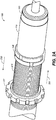
Figure 1A is a perspective view of a shock assembly with a wear sleeve, in accordance with an embodiment. -
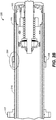
Figure 1B is a cross-section view of the shock assembly with a wear sleeve, in accordance with an embodiment. -
Figure 1C is a detail view of a retaining feature for retaining the wear sleeve, in accordance with an embodiment. -
Figure 2A is a perspective view of a shock assembly with a crossover ring retained adjustable wear sleeve, in accordance with an embodiment. -
Figure 2B is a cross-section view of the shock assembly with crossover ring retained adjustable wear sleeve ofFigure 2A , in accordance with an embodiment. -
Figure 2C is a detail view of the crossover ring retaining the wear sleeve ofFigure 2B , in accordance with an embodiment. -
Figure 3 is a cross-section view of a shock assembly with a non-adjustable wear sleeve replacing a spring adapter and held in place by spring preload, in accordance with an embodiment. - The drawings referred to in this description should be understood as not being drawn to scale except if specifically noted.
- The detailed description set forth below in connection with the appended drawings is intended as a description of various embodiments of the present invention and is not intended to represent the only embodiments in which the present invention is to be practiced. Each embodiment described in this disclosure is provided merely as an example or illustration of the present invention, and should not necessarily be construed as preferred or advantageous over other embodiments. In some instances, well known methods, procedures, and objects have not been described in detail as not to unnecessarily obscure aspects of the present disclosure.
- Embodiments disclosed herein, provide a wear sleeve that is placed outside of the shock body and between the shock body and at least a spring coupler to provide previously unavailable levels of wear resistance for the shock body. In one embodiment, the shock assemblies discussed herein are used in applications such as bicycles, motorcycles, all-terrain vehicles (ATV), Side-by-Sides, utility vehicles (UTV), snowmobiles, scooters, recreational off-highway vehicles (ROV), multipurpose off-highway utility vehicles (MOHUV), personal watercrafts (PWC), and the like. However, it should be appreciated that the wear sleeve can be used with almost any single spring or multi spring damper.
- In one embodiment, the wear sleeve is a modular component or set of components that slides over existing shock bodies. In one embodiment, the modular design allows the wear sleeve to be retroactively added to existing shock assemblies as well as being used in new shock assemblies.
- With reference now to
Figure 1A , a perspective view of ashock assembly 100 with a wear sleeve is shown in accordance with an embodiment. In one embodiment,shock assembly 100 is a dual spring shock assembly. However, it should be appreciated that in another embodiment,shock assembly 100 may use more than two springs. - In one embodiment,
shock assembly 100 includes ashock body 105 with a main chamber and a damping piston coupled with ashaft 130. In one embodiment,shock assembly 100 also includes aspring coupler 111, aprimary spring 113, atender spring 116, apreload flange 117, and thewear sleeve 110. - In one embodiment,
shock assembly 100 includes an optionalexternal reservoir 125 having a floating piston and pressurized gas to compensate for a reduction in volume in the main chamber asshaft 130 moves into the shock body. In its basic form, the main chamber works in conjunction with the one or more springs to control the speed of movement of theshaft 130 by metering incompressible fluid from one side of the damper piston to the other (or to and from the optional external reservoir 125) as the damper travels through the main chamber. - In one embodiment,
spring coupler 111 is located betweenprimary spring 113 andtender spring 116. In one embodiment,tender spring 116 abuts preloadflange 117 at one end andspring coupler 111 at the other and has aresting length 116L. In one embodiment,primary spring 113 abutsspring coupler 111 at one end andlower flange 103 at the other and has aresting length 113L. - In general, a dual-spring type of
shock assembly 100 enables an initial lighter stiffness rate for regular operation, but will transition to a harder stiffness rate upon encounter of a compression causing event. For example, in one embodiment, the initial stiffness ofshock assembly 100 is set to a relatively soft stiffness. Asshock assembly 100 compresses, so will theprimary spring 113 andtender spring 116, until a crossover is reached. Once the crossover is reached,tender spring 116 will no longer be part of the spring stiffness calculation and the rest of the spring compression is placed onprimary spring 113. At that time, the spring rate is increased to the spring stiffness ofprimary spring 113. In other words, the stiffness ofshock assembly 100 is increased to a firmer stiffness. - In general, in
shock assembly 100, the two springs are stacked together and provide a modified initial spring rate. The modified initial spring rate is often defined by (tender spring rate * primary spring rate) divided by (tender spring rate + primary spring rate). - For example, if the tender spring rate is 150 and the primary spring rate is 100, the initial spring rate is (150∗100)/(150+100) or 86. This will be the spring rate until the crossover is reached. At that time, the spring rate will change to the primary spring rate of 100. In one embodiment, this is identified by a dual rate: 86/100.
- In one embodiment, by adjusting the location of the crossover, the length of the stroke of
shock assembly 100 at the first spring rate is defined. For example, ifshock assembly 100 has a 305mm (12 inch) stroke and the crossover is set at 102mm (4 inch) of stroke,shock assembly 100 will use the lighter spring rate (E.g., 86) for the first 102mm (4 inches) of travel and then transition to the heavier spring rate (e.g., 100) for any remaining compression. - In one embodiment,
shock assembly 100 also includesupper eyelet 101 andlower eyelet 102 forcoupling shock assembly 100 with a suspension system. Theupper eyelet 101 andlower eyelet 102 are used for mounting one end of the shock assembly to a static portion of the vehicle and the other end of the shock assembly to a dynamic portion such as a retaining component or assembly that retains a wheel(s) (or ski, track, hull, etc.). Although eyelets are shown, it should be appreciated that the mounting systems may be bolts, welds, or the like, the use of eyelets is provided as one embodiment and for purposes of clarity. - Although the eyelets are labeled as
upper eyelet 101 andlower eyelet 102, this is done for purposes of defining relative motion of one or more of the components ofshock assembly 100. Thus, it should be appreciated that in one embodiment, (such as an inverted scenario) the mounting ofshock assembly 100 could be with theupper eyelet 101 being at a lower point (such as closer to the wheel retaining assembly) while thelower eyelet 102 would actually be at a higher point on the vehicle than upper eyelet 101 (e.g., such as at the frame of the vehicle). - Although a dual-spring type of
shock assembly 100 is used in the following discussion, it should be appreciated that in one embodiment, thewear sleeve 110 could be used in a single spring shock assembly and provide protection to theshock body 105 from the single spring or from other impact events such as rocks, branches, roots, curbs, or the like, that may be encountered by the shock assembly. - Referring now to
Figure 1B , a cross-section view of ashock assembly 100 with awear sleeve 110 around a portion of ashock body 105 is shown in accordance with an embodiment. Inshock assembly 100, a number of components are shown. However, it should be appreciated that in other embodiments, there may be more or fewer components, the components may be arranged in different configurations, and the like. - In one embodiment, the
shock body 105 is aluminum. In one embodiment, theshock body 105 also includes an anodized coating over the aluminum. In another embodiment, theshock body 105 could be made of a different material such as a different metal, composite, or combination thereof. - In one embodiment, during vehicle operation the
spring coupler 111 will move axially (e.g., back-and-forth in the axial directions indicated by arrow 127) along a portion of the length of the shock body 105 (e.g., the range of motion 193) as theshock assembly 100 moves through compression and rebound strokes. - For example, when the
shock assembly 100 is under compression, theprimary spring 113 and/ortender spring 116 will be compressed andspring coupler 111 will move axially (as indicated by arrow 127) along theshock body 105 toward thepreload flange 117. When theshock assembly 100 is in a rebound stroke, theprimary spring 113 and/or thetender spring 116 will decompress and thespring coupler 111 will move axially (as indicated by arrow 127) along theshock body 105 away from thepreload flange 117. - Although the
spring coupler 111 is designed to moves axially along theshock body 105, manufacturing tolerances for theprimary spring 113 and/or thetender spring 116 can cause imperfect axial motion of thespring coupler 111. This imperfect axial motion ofspring coupler 111 can cause friction betweenspring coupler 111 and a portion ofshock body 105. - Moreover, in a muddy (gravely, sandy, or the like) environment, small particles can make their way between the
spring coupler 111 and theshock body 105 to increase the friction (and thus the wear) that is occurring between thespring coupler 111 and theshock body 105. Further, any damage to theprimary spring 113 and/or thetender spring 116 can also increase the imperfect axial motion of thespring coupler 111. - In one embodiment, the
wear sleeve 110 is placed between thespring coupler 111 and theshock body 105 such that the friction (and thus the wear) from the motion ofspring coupler 111 and any particles thereunder are moved fromshock body 105 to wearsleeve 110. - In one embodiment, the
wear sleeve 110 has an inner diameter (ID) that is larger than an outer diameter (OD) of theshock body 105 such that thewear sleeve 110 will fit around the exterior portion of theshock body 105. Thewear sleeve 110 also has an OD that is smaller than the ID of spring coupler 111 (and also the ID of theprimary spring 113, thetender spring 116, etc.) such that wearsleeve 110 will fit around the exterior portion of theshock body 105 while fitting inside of the spring coupler 111 (and in one embodiment, theprimary spring 113,tender spring 116, etc.). - In one embodiment, wear
sleeve 110 will extend axially (as shown by arrow 127) along the shock body 115 at least as far as a range ofmotion 193 of thespring coupler 111. In one embodiment, wearsleeve 110 will extend axially (as shown by arrow 127) along the entire length of shock body 115 as shown bylength 196. In one embodiment, wearsleeve 110 will extend axially (as shown by arrow 127) along some length of shock body 115 that is less than the full length indicated bylength 196 and more than the range ofmotion 193 length. - By installing
wear sleeve 110 intoshock assembly 100, instead of having thespring coupler 111 in frictional contact withshock body 105, thespring coupler 111 will be in frictional contact withwear sleeve 110 whilewear sleeve 110 is fixed in position aboutshock body 105. In so doing, thewear sleeve 110 provides wear resistance between theshock body 105 and anyshock assembly 100 components that are outside of the OD of the wear sleeve 110 (e.g.,spring coupler 111,primary spring 113, tender spring 116), such that the previously occurring wear (or friction) on theshock body 105 will now occur onwear sleeve 110. - This previously occurring wear (or friction) will include the friction caused by any imperfect axial motion of the
spring coupler 111, any damage to theprimary spring 113 and/or thetender spring 116 that will cause additional imperfect axial motion of thespring coupler 111, small particles make their way between thespring coupler 111 and wearsleeve 110, and the like. - Thus, wear
sleeve 110 will be the recipient of the friction (or wear) that would otherwise occur between thespring coupler 111,primary spring 113 and/or thetender spring 116 and theshock body 105. - In one embodiment, wear
sleeve 110 is installed betweenshock body 105 and spring coupler 111 (and in one embodiment a portion ofprimary spring 113, and or some or all of the tender spring 116) and held in a fixed position with respect toshock body 105 by a retainingfeature 155 which is shown in further detail inFigure 1C . - In one embodiment, the thickness of
wear sleeve 110 is approximately 1.14mm (45 thousandths of an inch). In one embodiment, thewear sleeve 110 is steel. In one embodiment, thewear sleeve 110 is stainless steel. In one embodiment, wearsleeve 110 is a metal such as aluminum, titanium, copper, brass, steel, or the like. In one embodiment, wearsleeve 110 is coated with a protective coating such as a melanite coating (e.g., carbon nitriding) or the like. - In one
embodiment wear sleeve 110 is comprised of a composite material such as, but not limited to, glass filled nylon (such as for example, 33% glass reinforced Nylon 6/6), injection molded carbon fiber, carbon fiber with reinforced nylon, compression molding, composite layering, nylon reinforced with carbon fibers, chopped carbon fibers, a plastic, polymer, other long fiber-reinforced plastics, or the like. - In one embodiment, wear
sleeve 110 could be formed from a combination of materials such as an outer harder layer such as steel and an inner composite material. In one embodiment, by forming thewear sleeve 110 from a combination of materials, the outer portion ofwear sleeve 110 would have the increased wear resilience while the overall weight ofwear sleeve 110 would be reduced. - With reference now to
Figure 1C , adetail view 150 ofFigure 1B is shown in accordance with one embodiment. In one embodiment,detail view 150 shows a retainingfeature 155 used to retainwear sleeve 110 at a fixed position/location onshock body 105. - For example, in one embodiment, wear
sleeve 110 will have an indent (crimp, tab, etc.) and aretaining feature 155 will be fixedly coupled withshock body 105. As such, whenwear sleeve 110 is placed onshock body 105 it will slide alongshock body 105 until the indent inwear sleeve 110encounters retaining feature 155 onshock body 105. At that point, wearsleeve 110 will be fixedly coupled withshock body 105 in the designated position. - In one embodiment,
shock body 105 will have an indent (crimp, tab, etc.) and wearsleeve 110 will have aretaining feature 155. As such, whenwear sleeve 110 is placed onshock body 105 it will slide alongshock body 105 until the retainingfeature 155 ofwear sleeve 110 encounters the indent onshock body 105. At that point, wearsleeve 110 will be fixedly coupled withshock body 105 in the designated position. - In one embodiment,
retainer 155 is a snap ring retainer. In one embodiment,retainer 155 is another type of retaining feature for retaining the fixed position ofwear sleeve 110 with respect to theshock body 105. In one embodiment,retainer 155 could be a crimp, tab, indent, or the like, feature that is used at one or both of thewear sleeve 110 andshock body 105 to retain the position/location ofwear sleeve 110 with respect toshock body 105. - Referring now to
Figure 2A , a perspective view of ashock assembly 100 with anadjustable wear sleeve 110 having acrossover ring 238 coupled therewith is shown in accordance with an embodiment. In one embodiment,shock body 105 includes a surface features such as threadedsection 215. - In one embodiment, threaded
section 215 traverses a portion of the exterior surface ofshock body 105. In one embodiment, threadedsection 215 is formed onshock body 105 during the manufacture ofshock body 105. Although one embodiment discusses a threadedsection 215, in another embodiment, instead of threads, the surface feature could be ridges, indents, or the like. - In general, the
crossover ring 238 includes an adjustable setting capability that allows a user to change the location ofwear sleeve 110 with respect toshock body 105. For example, the location ofwear sleeve 110 is adjusted by rotating thecrossover ring 238 axially aroundshock body 105 along the threadedsection 215. - For example, when the
crossover ring 238 is rotated clockwise aboutshock body 105, the threadedsection 215 will cause thecrossover ring 238 and wearsleeve 110 to move indirection 232. In contrast, when thecrossover ring 238 is rotated anti-clockwise aboutshock body 105, the threadedsection 215 will cause thecrossover ring 238 and wearsleeve 110 to move indirection 231. - With reference now to
Figure 2B , across-section view 225 of theshock assembly 100 with theadjustable crossover ring 238 retainedwear sleeve 110 ofFigure 2A is shown in accordance with an embodiment. In one embodiment, using threadedcrossover ring 238 to retain thewear sleeve 110 will provide a level of adjustability for wear sleeve along the threadedsection 215 ofshock body 105 that will be available to a mechanic, an end user, or the like. - In one embodiment, by using threaded
crossover ring 238 to adjustably couple wearsleeve 110 with theshock body 105, thewear sleeve 110 will be retroactively compatible with threaded shock bodies, such as, for example shock bodies with different diameters (e.g., 2.5, 3.0, etc.) and the like. Moreover, since thewear sleeve 110 is coupled with theshock body 105 by threading thecrossover ring 238 along the existing threadedsection 215, the location of thewear sleeve 110 is adjustable with respect to theshock body 105. - In addition, since the
shock body 105 ofFigure 2A-2C already includes a threadedsection 215 used bypreload flange 117 to adjust the preload.Shock body 105 does not need to be customized for the application of thewear sleeve 110 to be added thereto. Instead, in one embodiment, theshock body 105 is a standard part set. Thus, in one embodiment, thewear sleeve 110 coupled with thecrossover ring 238 can be incorporated into any existingshock assembly 100 with a threadedshock body 105. In one embodiment, the incorporation of thewear sleeve 110 into an existing shock body would include a replacement of a preexisting crossover ring with thecrossover ring 238. - In one embodiment, a limit is provided with
shock assembly 100 to stop a user from adjusting the end of thewear sleeve 110 off of theshock body 105 and thereby possibly contacting the spring retainer from the rod end of theshock assembly 100. - Referring now to
Figure 2C , adetail view 250 of thecrossover ring 238 retaining thewear sleeve 110 ofFigure 2B is shown in accordance with an embodiment. In one embodiment, thewear sleeve 110 has abent end portion 265. In one embodiment,crossover ring 238 is fixedly coupled with thewear sleeve 110 using abent end portion 265 that is held bycrossover ring 238. - With reference now to
Figure 3 , a cross-section view of ashock assembly 100 with anon-adjustable wear sleeve 110 about at least a portion of theshock body 105 is shown in accordance with an embodiment. In general, many of the components ofFigure 3 are similar to those ofFigures 1A-2C , and as such, the discussion of the similar parts and their operation is not repeated for purposes of clarity, but is incorporated herein by reference. - In one embodiment,
shock assembly 100 ofFigure 3 replaces an existing component (e.g., a spring adapter) with the preload ring 317. In one embodiment, wearsleeve 110 has atab 305 that allows thewear sleeve 110 to be non-adjustably held in place about theshock body 105 by the spring preload force from an external spring (such as tender spring 116) against the preload ring 317. In general, the embodiment ofFigure 3 is useful in shock assemblies that use a coil bound tender (e.g., shock assemblies that don't have crossover rings). - In one embodiment, an added benefit of
wear sleeve 110 is that theshock body 105 can be customized (e.g., lightened, reduced in thickness, etc.). For example, the addition of thewear sleeve 110 provides a layer of wear resistance as well as an amount of puncture resistance from external items (such as rocks, branches, curbs, etc.) to shockbody 105. - In one embodiment, the performance goals of
wear sleeve 110 can be used as a factor for the material(s) used to makewear sleeve 110, the thickness ofwear sleeve 110, the overall length ofwear sleeve 110, the method for couplingwear sleeve 110 withshock body 105, and the like. For example, awear sleeve 110 for a road bike used by an amateur rider may include a design criterion where the weight is valued more than an expected lifespan, the length ofwear sleeve 110 alongshock body 105 is slightly larger than the expected travel of spring coupler 111 (e.g., 30%), and cost is an important factor. In contrast, in awear sleeve 110 for a road bike used by a professional rider, a design criterion may be based on weight, where cost is somewhat important, the length ofwear sleeve 110 alongshock body 105 is minimally larger than the expected travel of spring coupler 111 (e.g., 10%),and the expected lifespan is reduced to the length of a race (or two races, etc.). - In one embodiment, the
wear sleeve 110 for an average mountain bike used by an amateur rider would include a design criterion where the expected lifespan is valued more than the weight, the length ofwear sleeve 110 alongshock body 105 is quite a bit larger than the expected travel of spring coupler 111 (e.g., 55% larger) to also reduce wear to shockbody 105 from, rocks, branches,primary spring 113 and/or thetender spring 116, etc., and cost is also an important factor. - In contrast, in the
wear sleeve 110 for a mountain bike used by a professional rider, a design criterion may be based on protection, e.g., the length ofwear sleeve 110 alongshock body 105 is quite a bit larger than the expected travel of spring coupler 111 (e.g., 75% larger) to also reduce wear to shockbody 105 from rocks, branches,primary spring 113 and/or thetender spring 116, etc., where cost and weight are somewhat important, and the expected lifespan is reduced to the length of a race weekend, a season, or the like. - Therefore, in one embodiment, the design of the
wear sleeve 110 may be modified by different material use, different durability life, a different temperature stability threshold, designed to work with non-standard springs (having different (IDs) than the standard springs used by the platform, etc. In other words, in one embodiment, the thickness, material, and manufacture ofwear sleeve 110 would be different based on different use cases, rider preferences, tolerances, purchase price, and the like. - For example, in one embodiment, wear
sleeve 110 could be formed from a lightweight material that provides the wear protection forshock body 105 but has a reduced durability lifespan as compared to awear sleeve 110 formed from a heavier material. A composite orlightweight wear sleeve 110 would be significantly lighter than a heaviersteel wear sleeve 110, but would likely have much faster wear characteristics. As such, the user could optionally select the lighterweight wear sleeve 110 with the understanding that it will have to be replaced more often than aheavyweight wear sleeve 110. - Moreover,
different wear sleeve 110 features would also include different replacement intervals. The wear intervals could be materially based and include aspects such as, but not limited to, after a given time period, after a number of hours of use, when imbedded wear indicators appear (or make noise, etc.), when visible wear is identified, and the like. Moreover, the wear intervals could also be adjusted based on environmental (or terrain) use such as on-road use, off-road use, sand, gravel, mud, silt, dirt, water, etc. For example, thewear sleeve 110 will have a longer use life in an on-road environment and a shorter expected life use in a muddy off-road environment. In another example, a racer might require a higher temperature stability in thewear sleeve 110 than a casual rider. - Thus, in one embodiment, the manufacturer could provide a number of
different wear sleeve 110 material options that would allow a user to select the desired option based on weight, wear characteristic, replacement intervals, temperature stability thresholds, expected or most often encountered environments/terrains, non-standard spring use, and the like. For example, a road rider may want to use a lighterweight wear sleeve 110 which would have an expected useful lifespan of 1-3 years in an on-road environment, while a motocross rider would not use the same lighterweight wear sleeve 110 because it would have an expected useful lifespan of a month in a muddy, sandy, gritty, off-road environment. In another example, a Baja Racer may use a heavierweight wear sleeve 110 becauseshock body 105 protection is valued higher than weight saving. - In one embodiment, wear
sleeve 110 has performance goals such as, at least a 5000-mile durability life, an adjustable preload, an adjustable crossover, is temperature stable to at least 350 degrees Fahrenheit, and can work with standard springs (having IDs used by the platform). In other words, thewear sleeve 110 would not extend the OD of the shock body to an OD that did not operationally fit within the ID of the standard spring(s). - The foregoing Description of Embodiments is not intended to be exhaustive or to limit the embodiments to the precise form described. Instead, example embodiments in this Description of Embodiments have been presented in order to enable persons of skill in the art to make and use embodiments of the described subject matter. Moreover, various embodiments have been described in various combinations. However, any two or more embodiments could be combined. Although some embodiments have been described in a language specific to structural features and/or methodological acts, it is to be understood that the subject matter defined in the appended claims is not necessarily limited to the specific features or acts described above. Rather, the specific features and acts described above are disclosed by way of illustration and as example forms of implementing the claims and their equivalents.
Claims (15)
- A shock assembly comprising:a shock body having an outer diameter (OD);a spring coupler having an inner diameter (ID); anda wear sleeve comprising:a wear sleeve ID that is larger than said OD of the shock body; anda wear sleeve OD that is smaller than said ID of the spring coupler, such that the wear sleeve will fit about the outside of said shock body, and between the shock body and the spring coupler.
- A shock assembly as claimed in Claim 1, wherein said spring coupler has a range of motion and said wear sleeve has a wear sleeve axial length that is at least as long as said range of motion.
- A shock assembly as claimed in Claim 1 or 2, further comprising:
a retaining feature to fixedly couple said wear sleeve with said shock body at a given location. - A shock assembly as claimed in Claim 3, wherein said retaining feature comprises:a first portion of said retaining feature on said shock body and selected from a group consisting of: a crimp, a tab, and an indent; anda second portion fixedly coupled with the wear sleeve, and optionally wherein said second portion comprises a snap ring.
- A shock assembly as claimed in Claim 3, wherein said retaining feature comprises:a first portion of said retaining feature on said wear sleeve and selected from a group consisting of: a crimp, a tab, and an indent; anda second portion fixedly coupled with said shock body, and optionally wherein said second portion comprises a snap ring.
- A shock assembly as claimed in Claim 3 wherein said retaining feature comprises a preload ring.
- A shock assembly as claimed in claim 6, wherein said retaining feature further comprises:an external spring comprising an external spring ID, said external spring located between said preload ring and said spring coupler, said external spring to provide a spring force between both said preload ring and said spring coupler;said wear sleeve OD smaller than said external spring ID; anda tab on an end of said wear sleeve, said tab to fit between said preload ring and said external spring, such that said spring force of said external spring fixedly couples said tab of said wear sleeve with said preload ring.
- A shock assembly as claimed in any preceding Claim, further comprising:a threaded section of said shock body;a threaded crossover ring adjustably coupleable with said threaded section of said shock body; andan end portion of said wear sleeve fixedly coupled with said threaded crossover ring, such that a location of said wear sleeve is adjustable with respect to said shock body.
- A shock assembly as claimed in any preceding Claim, wherein said wear sleeve further comprises:a thickness of approximately 1.14mm (45 thousandths of an inch);a glass filled nylon composite material or stainless steel; anda melanite coating.
- A shock assembly as claimed in Claim 2, or any claim dependent directly or indirectly therein, further comprisinga preload flange;a limit at a bottom of said shock body; andwherein said wear sleeve axial length extends from said preload flange to said limit.
- A shock assembly as claimed in Claim 2, or any claim dependent directly or indirectly thereon, further comprisinga preload ring; andsaid wear sleeve axial length extends from said preload ring through said spring coupler range of motion.
- For use in a shock assembly of any of Claims 1 to 11, a wear sleeve comprising the wear sleeve features of any of Claims 1 to 3, 5, and 7 to 11.
- For use in a shock assembly of any of Claims 1 to 11, a shock body comprising a retaining feature to fixedly couple said wear sleeve with said shock body at a given location, and optionally wherein said retaining feature comprises the first portion of claim 4, and optionally the shock body further comprising the features of claim 8.
- A shock body as claimed in Claim 13, wherein said retaining feature comprises either:the first portion of said retaining feature selected from a group consisting of: a crimp, a tab, and an indent; orthe second portion of said retaining feature, optionally the second portion comprising a snap ring.
- A vehicle comprising a shock assembly as claimed in any of Claims 1 to 11.
Applications Claiming Priority (2)
| Application Number | Priority Date | Filing Date | Title |
|---|---|---|---|
| US202063001057P | 2020-03-27 | 2020-03-27 | |
| US17/213,078 US12128723B2 (en) | 2020-03-27 | 2021-03-25 | Wear sleeve for a shock body |
Publications (1)
| Publication Number | Publication Date |
|---|---|
| EP3885605A1 true EP3885605A1 (en) | 2021-09-29 |
Family
ID=75252417
Family Applications (1)
| Application Number | Title | Priority Date | Filing Date |
|---|---|---|---|
| EP21165231.8A Pending EP3885605A1 (en) | 2020-03-27 | 2021-03-26 | Wear sleeve for a shock body |
Country Status (2)
| Country | Link |
|---|---|
| US (2) | US12128723B2 (en) |
| EP (1) | EP3885605A1 (en) |
Cited By (2)
| Publication number | Priority date | Publication date | Assignee | Title |
|---|---|---|---|---|
| US20230226869A1 (en) * | 2022-01-20 | 2023-07-20 | Westcott Designs Inc. | Preload collar for a vehicle suspension system |
| US12546377B2 (en) * | 2023-04-13 | 2026-02-10 | Hitachi Astemo, Ltd. | Shock absorber |
Families Citing this family (5)
| Publication number | Priority date | Publication date | Assignee | Title |
|---|---|---|---|---|
| GB2585682A (en) * | 2019-07-11 | 2021-01-20 | R5 Mss Ltd | Suspension adjustment assembly |
| US12077028B2 (en) * | 2020-03-03 | 2024-09-03 | Shock Therapy Suspension, Inc. | Coilover shock with adjustable crossover |
| JP2024153151A (en) * | 2023-04-17 | 2024-10-29 | 日立Astemo株式会社 | Shock absorber |
| DE102023118270A1 (en) * | 2023-07-11 | 2025-01-16 | Thyssenkrupp Ag | Height level adjustment system for a chassis of a motor vehicle |
| CN120991021B (en) * | 2025-10-20 | 2025-12-30 | 江苏科曼赛特减振器有限公司 | Vibration damping structure and vibration damping device |
Citations (11)
| Publication number | Priority date | Publication date | Assignee | Title |
|---|---|---|---|---|
| US2902274A (en) * | 1957-06-11 | 1959-09-01 | Monroe Auto Equipment Co | Vehicle suspension system |
| US4521002A (en) * | 1983-03-09 | 1985-06-04 | Maremont Corporation | Series spring shock absorbers |
| EP0259010A2 (en) * | 1986-09-02 | 1988-03-09 | General Motors Corporation | Method of manufacturing a modular piston and piston rod assembly |
| JP3048245U (en) * | 1997-10-21 | 1998-05-06 | 株式会社タナベ | Vehicle coil spring |
| JP2002139087A (en) * | 2000-10-31 | 2002-05-17 | Yamaha Motor Co Ltd | Shock absorber |
| US20050189685A1 (en) * | 2004-03-01 | 2005-09-01 | Frank Verriet | Dual spring rate preload module with air adjustment |
| US7216861B1 (en) * | 2005-09-07 | 2007-05-15 | Big Shot Performance, Llc | Protective sleeve for adjustable shock absorber |
| US20070144844A1 (en) * | 2005-10-31 | 2007-06-28 | Brent Riley | Floating spring divider for a shock absorber in automobile |
| DE102007060085A1 (en) * | 2007-12-13 | 2009-06-18 | Durferrit Gmbh | Process for producing corrosion-resistant surfaces of nitrided or nitrocarburised steel components |
| JP2019002459A (en) * | 2017-06-14 | 2019-01-10 | 本田技研工業株式会社 | Vehicle suspension |
| US10577018B2 (en) * | 2016-06-22 | 2020-03-03 | Tenneco Automotive Operating Company Inc. | Steering stabilizer for a motor vehicle |
Family Cites Families (28)
| Publication number | Priority date | Publication date | Assignee | Title |
|---|---|---|---|---|
| US2896938A (en) * | 1954-05-06 | 1959-07-28 | Monroe Auto Equipment Co | Vehicle suspension device |
| US3157393A (en) * | 1962-07-16 | 1964-11-17 | Monroe Auto Equipment Co | Vehicle stabilizing unit |
| US3263983A (en) * | 1963-12-30 | 1966-08-02 | Ford Motor Co | Shock absorber and auxiliary spring unit |
| US3752498A (en) * | 1971-10-07 | 1973-08-14 | Gen Motors Corp | Oleo-pneumatic suspension assembly |
| GB1428413A (en) * | 1973-01-04 | 1976-03-17 | Girling Ltd | Telescopic suspension units |
| US3951391A (en) * | 1974-02-22 | 1976-04-20 | Papousek Robert D | Shock absorber |
| US3893702A (en) * | 1974-05-02 | 1975-07-08 | Johan H Keijzer | Vehicle suspension system |
| US4436118A (en) * | 1977-07-25 | 1984-03-13 | Smith International, Inc. | Sleeved drill pipe |
| US5316113A (en) * | 1987-11-19 | 1994-05-31 | Atsugi Motor Parts Company Ltd. | Hydraulic shock absorber |
| US5454550A (en) * | 1994-08-09 | 1995-10-03 | Christopherson Group | Dampening shock absorber |
| US5477948A (en) * | 1995-03-06 | 1995-12-26 | Stevens; Anthony | Shock absorber adapter and method |
| US5996982A (en) * | 1997-07-29 | 1999-12-07 | Gabriel Ride Control Products, Inc. | Vehicle shock absorber with coil over preload adjustment |
| US5961106A (en) * | 1998-06-08 | 1999-10-05 | Shaffer; Theodore E. | Vehicle shock absorber assembly having height adjustment |
| US20020038929A1 (en) * | 2000-06-23 | 2002-04-04 | Now Leo Martin | Shock absorber |
| US7163216B2 (en) * | 2003-05-09 | 2007-01-16 | The Pullman Company | One end adjustable torque rod |
| JP2006194427A (en) * | 2004-12-16 | 2006-07-27 | Yamaha Motor Co Ltd | Spring spacer, spring, suspension spring, device, suspension device, and vehicle |
| US7293764B2 (en) * | 2006-02-03 | 2007-11-13 | Neotek Co., Ltd. | Adjusting mechanism with a helical spring of large diameter |
| DE112008000335T5 (en) * | 2007-02-20 | 2010-01-14 | Tenneco Automotive Operating Company Inc., Lake Forest | Positioning device and method for exact vehicle heights |
| US7469624B1 (en) * | 2007-11-12 | 2008-12-30 | Jason Adams | Direct drive retrofit for rifles |
| US9686899B2 (en) * | 2013-08-21 | 2017-06-27 | Cnh Industrial America Llc | Spring guide |
| JP6240442B2 (en) * | 2013-09-06 | 2017-11-29 | 株式会社ショーワ | Spring seat |
| KR101876915B1 (en) * | 2013-10-28 | 2018-08-09 | 주식회사 만도 | Piston valve assembly of shock absorber |
| US9027938B1 (en) * | 2013-11-15 | 2015-05-12 | David Kasian | Suspension lift kit for quad cycle |
| US9657801B2 (en) * | 2014-01-08 | 2017-05-23 | John E. Hansen | Shock absorber protector |
| US9162548B1 (en) * | 2014-07-15 | 2015-10-20 | GM Global Technology Operations LLC | Vehicle and a suspension assembly for a vehicle |
| US9174504B1 (en) * | 2014-08-26 | 2015-11-03 | Douglas Hunter Powell | Lock and load control arm |
| CN107208726B (en) * | 2015-02-03 | 2019-10-01 | 天纳克汽车营运公司 | Secondary damping components for shock absorbers |
| CN107429774B (en) * | 2015-02-06 | 2019-09-27 | 天纳克汽车营运公司 | Secondary damping components for shock absorbers |
-
2021
- 2021-03-25 US US17/213,078 patent/US12128723B2/en active Active
- 2021-03-26 EP EP21165231.8A patent/EP3885605A1/en active Pending
-
2024
- 2024-10-08 US US18/909,627 patent/US20250026166A1/en active Pending
Patent Citations (11)
| Publication number | Priority date | Publication date | Assignee | Title |
|---|---|---|---|---|
| US2902274A (en) * | 1957-06-11 | 1959-09-01 | Monroe Auto Equipment Co | Vehicle suspension system |
| US4521002A (en) * | 1983-03-09 | 1985-06-04 | Maremont Corporation | Series spring shock absorbers |
| EP0259010A2 (en) * | 1986-09-02 | 1988-03-09 | General Motors Corporation | Method of manufacturing a modular piston and piston rod assembly |
| JP3048245U (en) * | 1997-10-21 | 1998-05-06 | 株式会社タナベ | Vehicle coil spring |
| JP2002139087A (en) * | 2000-10-31 | 2002-05-17 | Yamaha Motor Co Ltd | Shock absorber |
| US20050189685A1 (en) * | 2004-03-01 | 2005-09-01 | Frank Verriet | Dual spring rate preload module with air adjustment |
| US7216861B1 (en) * | 2005-09-07 | 2007-05-15 | Big Shot Performance, Llc | Protective sleeve for adjustable shock absorber |
| US20070144844A1 (en) * | 2005-10-31 | 2007-06-28 | Brent Riley | Floating spring divider for a shock absorber in automobile |
| DE102007060085A1 (en) * | 2007-12-13 | 2009-06-18 | Durferrit Gmbh | Process for producing corrosion-resistant surfaces of nitrided or nitrocarburised steel components |
| US10577018B2 (en) * | 2016-06-22 | 2020-03-03 | Tenneco Automotive Operating Company Inc. | Steering stabilizer for a motor vehicle |
| JP2019002459A (en) * | 2017-06-14 | 2019-01-10 | 本田技研工業株式会社 | Vehicle suspension |
Cited By (2)
| Publication number | Priority date | Publication date | Assignee | Title |
|---|---|---|---|---|
| US20230226869A1 (en) * | 2022-01-20 | 2023-07-20 | Westcott Designs Inc. | Preload collar for a vehicle suspension system |
| US12546377B2 (en) * | 2023-04-13 | 2026-02-10 | Hitachi Astemo, Ltd. | Shock absorber |
Also Published As
| Publication number | Publication date |
|---|---|
| US20250026166A1 (en) | 2025-01-23 |
| US12128723B2 (en) | 2024-10-29 |
| US20210300139A1 (en) | 2021-09-30 |
Similar Documents
| Publication | Publication Date | Title |
|---|---|---|
| US12128723B2 (en) | Wear sleeve for a shock body | |
| US12496867B2 (en) | Hydraulically-adjustable preload and/or cross-over | |
| TWI785069B (en) | Inline shock absorber with coil spring for a cycle wheel suspension assembly | |
| US7168726B2 (en) | Ultra lightweight, high efficiency bicycle suspension | |
| US8434772B2 (en) | Damper tube reinforcement sleeve | |
| US6109636A (en) | High efficiency bicycle frame suspension | |
| US8408569B2 (en) | Damper tube reinforcement sleeve | |
| CA2266576A1 (en) | Bicycle suspension system | |
| KR20150128682A (en) | Jounce bumper nose retaining feature for a shock absorber | |
| US11009094B1 (en) | System and method for using a piston face and shim in a shock absorber with varying port configurations | |
| EP2057064B1 (en) | Shock absorber | |
| US20140157978A1 (en) | Air shock absorber and straddle-type vehicle | |
| EP3392524B1 (en) | Variable friction tuning for shock absorption | |
| US20170240835A1 (en) | Lubrication Structure for a Shock Absorber of Vehicle | |
| JP6613095B2 (en) | Coil spring for suspension | |
| WO1999058392A1 (en) | Damping and spring system for suspension system | |
| CN1115293A (en) | Rear suspension frame for two wheeled vehicles | |
| EP4290090A1 (en) | Integrated bearing hardware for shock assembly | |
| US20250304206A1 (en) | Bicycle front forks having features to distribute lubricant | |
| US20260027863A1 (en) | Spring isolator and wear band | |
| CN221990837U (en) | Shock-absorbing structure for preventing mud | |
| Ahmadian et al. | A comparative analysis of passive twin tube and skyhook MRF dampers for motorcycle front suspensions | |
| EP0796782A2 (en) | Bicycle suspension | |
| JPS5940031A (en) | Vehicular spring supporting device | |
| US20210387473A1 (en) | Adjustable airless tire system with changeable supporting structures |
Legal Events
| Date | Code | Title | Description |
|---|---|---|---|
| PUAI | Public reference made under article 153(3) epc to a published international application that has entered the european phase |
Free format text: ORIGINAL CODE: 0009012 |
|
| STAA | Information on the status of an ep patent application or granted ep patent |
Free format text: STATUS: THE APPLICATION HAS BEEN PUBLISHED |
|
| AK | Designated contracting states |
Kind code of ref document: A1 Designated state(s): AL AT BE BG CH CY CZ DE DK EE ES FI FR GB GR HR HU IE IS IT LI LT LU LV MC MK MT NL NO PL PT RO RS SE SI SK SM TR |
|
| STAA | Information on the status of an ep patent application or granted ep patent |
Free format text: STATUS: REQUEST FOR EXAMINATION WAS MADE |
|
| 17P | Request for examination filed |
Effective date: 20211202 |
|
| RBV | Designated contracting states (corrected) |
Designated state(s): AL AT BE BG CH CY CZ DE DK EE ES FI FR GB GR HR HU IE IS IT LI LT LU LV MC MK MT NL NO PL PT RO RS SE SI SK SM TR |
|
| P01 | Opt-out of the competence of the unified patent court (upc) registered |
Effective date: 20230522 |
|
| STAA | Information on the status of an ep patent application or granted ep patent |
Free format text: STATUS: EXAMINATION IS IN PROGRESS |
|
| 17Q | First examination report despatched |
Effective date: 20251202 |