EP3885593A1 - Bearing housing oil intake to supply dual bearing structure - Google Patents
Bearing housing oil intake to supply dual bearing structure Download PDFInfo
- Publication number
- EP3885593A1 EP3885593A1 EP21164577.5A EP21164577A EP3885593A1 EP 3885593 A1 EP3885593 A1 EP 3885593A1 EP 21164577 A EP21164577 A EP 21164577A EP 3885593 A1 EP3885593 A1 EP 3885593A1
- Authority
- EP
- European Patent Office
- Prior art keywords
- bearing
- oil
- sleeve
- housing
- inlet
- Prior art date
- Legal status (The legal status is an assumption and is not a legal conclusion. Google has not performed a legal analysis and makes no representation as to the accuracy of the status listed.)
- Granted
Links
Images




Classifications
-
- F—MECHANICAL ENGINEERING; LIGHTING; HEATING; WEAPONS; BLASTING
- F16—ENGINEERING ELEMENTS AND UNITS; GENERAL MEASURES FOR PRODUCING AND MAINTAINING EFFECTIVE FUNCTIONING OF MACHINES OR INSTALLATIONS; THERMAL INSULATION IN GENERAL
- F16C—SHAFTS; FLEXIBLE SHAFTS; ELEMENTS OR CRANKSHAFT MECHANISMS; ROTARY BODIES OTHER THAN GEARING ELEMENTS; BEARINGS
- F16C33/00—Parts of bearings; Special methods for making bearings or parts thereof
- F16C33/30—Parts of ball or roller bearings
- F16C33/66—Special parts or details in view of lubrication
- F16C33/6637—Special parts or details in view of lubrication with liquid lubricant
- F16C33/6659—Details of supply of the liquid to the bearing, e.g. passages or nozzles
-
- F—MECHANICAL ENGINEERING; LIGHTING; HEATING; WEAPONS; BLASTING
- F16—ENGINEERING ELEMENTS AND UNITS; GENERAL MEASURES FOR PRODUCING AND MAINTAINING EFFECTIVE FUNCTIONING OF MACHINES OR INSTALLATIONS; THERMAL INSULATION IN GENERAL
- F16C—SHAFTS; FLEXIBLE SHAFTS; ELEMENTS OR CRANKSHAFT MECHANISMS; ROTARY BODIES OTHER THAN GEARING ELEMENTS; BEARINGS
- F16C19/00—Bearings with rolling contact, for exclusively rotary movement
- F16C19/54—Systems consisting of a plurality of bearings with rolling friction
-
- F—MECHANICAL ENGINEERING; LIGHTING; HEATING; WEAPONS; BLASTING
- F16—ENGINEERING ELEMENTS AND UNITS; GENERAL MEASURES FOR PRODUCING AND MAINTAINING EFFECTIVE FUNCTIONING OF MACHINES OR INSTALLATIONS; THERMAL INSULATION IN GENERAL
- F16C—SHAFTS; FLEXIBLE SHAFTS; ELEMENTS OR CRANKSHAFT MECHANISMS; ROTARY BODIES OTHER THAN GEARING ELEMENTS; BEARINGS
- F16C27/00—Elastic or yielding bearings or bearing supports, for exclusively rotary movement
- F16C27/04—Ball or roller bearings, e.g. with resilient rolling bodies
- F16C27/045—Ball or roller bearings, e.g. with resilient rolling bodies with a fluid film, e.g. squeeze film damping
-
- F—MECHANICAL ENGINEERING; LIGHTING; HEATING; WEAPONS; BLASTING
- F16—ENGINEERING ELEMENTS AND UNITS; GENERAL MEASURES FOR PRODUCING AND MAINTAINING EFFECTIVE FUNCTIONING OF MACHINES OR INSTALLATIONS; THERMAL INSULATION IN GENERAL
- F16C—SHAFTS; FLEXIBLE SHAFTS; ELEMENTS OR CRANKSHAFT MECHANISMS; ROTARY BODIES OTHER THAN GEARING ELEMENTS; BEARINGS
- F16C33/00—Parts of bearings; Special methods for making bearings or parts thereof
- F16C33/30—Parts of ball or roller bearings
- F16C33/66—Special parts or details in view of lubrication
- F16C33/6637—Special parts or details in view of lubrication with liquid lubricant
- F16C33/6659—Details of supply of the liquid to the bearing, e.g. passages or nozzles
- F16C33/6662—Details of supply of the liquid to the bearing, e.g. passages or nozzles the liquid being carried by air or other gases, e.g. mist lubrication
-
- F—MECHANICAL ENGINEERING; LIGHTING; HEATING; WEAPONS; BLASTING
- F16—ENGINEERING ELEMENTS AND UNITS; GENERAL MEASURES FOR PRODUCING AND MAINTAINING EFFECTIVE FUNCTIONING OF MACHINES OR INSTALLATIONS; THERMAL INSULATION IN GENERAL
- F16C—SHAFTS; FLEXIBLE SHAFTS; ELEMENTS OR CRANKSHAFT MECHANISMS; ROTARY BODIES OTHER THAN GEARING ELEMENTS; BEARINGS
- F16C33/00—Parts of bearings; Special methods for making bearings or parts thereof
- F16C33/30—Parts of ball or roller bearings
- F16C33/66—Special parts or details in view of lubrication
- F16C33/6637—Special parts or details in view of lubrication with liquid lubricant
- F16C33/6685—Details of collecting or draining, e.g. returning the liquid to a sump
-
- F—MECHANICAL ENGINEERING; LIGHTING; HEATING; WEAPONS; BLASTING
- F16—ENGINEERING ELEMENTS AND UNITS; GENERAL MEASURES FOR PRODUCING AND MAINTAINING EFFECTIVE FUNCTIONING OF MACHINES OR INSTALLATIONS; THERMAL INSULATION IN GENERAL
- F16C—SHAFTS; FLEXIBLE SHAFTS; ELEMENTS OR CRANKSHAFT MECHANISMS; ROTARY BODIES OTHER THAN GEARING ELEMENTS; BEARINGS
- F16C35/00—Rigid support of bearing units; Housings, e.g. caps, covers
- F16C35/04—Rigid support of bearing units; Housings, e.g. caps, covers in the case of ball or roller bearings
- F16C35/06—Mounting or dismounting of ball or roller bearings; Fixing them onto shaft or in housing
- F16C35/07—Fixing them on the shaft or housing with interposition of an element
- F16C35/077—Fixing them on the shaft or housing with interposition of an element between housing and outer race ring
-
- F—MECHANICAL ENGINEERING; LIGHTING; HEATING; WEAPONS; BLASTING
- F16—ENGINEERING ELEMENTS AND UNITS; GENERAL MEASURES FOR PRODUCING AND MAINTAINING EFFECTIVE FUNCTIONING OF MACHINES OR INSTALLATIONS; THERMAL INSULATION IN GENERAL
- F16C—SHAFTS; FLEXIBLE SHAFTS; ELEMENTS OR CRANKSHAFT MECHANISMS; ROTARY BODIES OTHER THAN GEARING ELEMENTS; BEARINGS
- F16C19/00—Bearings with rolling contact, for exclusively rotary movement
- F16C19/22—Bearings with rolling contact, for exclusively rotary movement with bearing rollers essentially of the same size in one or more circular rows, e.g. needle bearings
- F16C19/24—Bearings with rolling contact, for exclusively rotary movement with bearing rollers essentially of the same size in one or more circular rows, e.g. needle bearings for radial load mainly
- F16C19/28—Bearings with rolling contact, for exclusively rotary movement with bearing rollers essentially of the same size in one or more circular rows, e.g. needle bearings for radial load mainly with two or more rows of rollers
-
- F—MECHANICAL ENGINEERING; LIGHTING; HEATING; WEAPONS; BLASTING
- F16—ENGINEERING ELEMENTS AND UNITS; GENERAL MEASURES FOR PRODUCING AND MAINTAINING EFFECTIVE FUNCTIONING OF MACHINES OR INSTALLATIONS; THERMAL INSULATION IN GENERAL
- F16C—SHAFTS; FLEXIBLE SHAFTS; ELEMENTS OR CRANKSHAFT MECHANISMS; ROTARY BODIES OTHER THAN GEARING ELEMENTS; BEARINGS
- F16C2326/00—Articles relating to transporting
- F16C2326/43—Aeroplanes; Helicopters
-
- F—MECHANICAL ENGINEERING; LIGHTING; HEATING; WEAPONS; BLASTING
- F16—ENGINEERING ELEMENTS AND UNITS; GENERAL MEASURES FOR PRODUCING AND MAINTAINING EFFECTIVE FUNCTIONING OF MACHINES OR INSTALLATIONS; THERMAL INSULATION IN GENERAL
- F16C—SHAFTS; FLEXIBLE SHAFTS; ELEMENTS OR CRANKSHAFT MECHANISMS; ROTARY BODIES OTHER THAN GEARING ELEMENTS; BEARINGS
- F16C2360/00—Engines or pumps
- F16C2360/23—Gas turbine engines
-
- F—MECHANICAL ENGINEERING; LIGHTING; HEATING; WEAPONS; BLASTING
- F16—ENGINEERING ELEMENTS AND UNITS; GENERAL MEASURES FOR PRODUCING AND MAINTAINING EFFECTIVE FUNCTIONING OF MACHINES OR INSTALLATIONS; THERMAL INSULATION IN GENERAL
- F16C—SHAFTS; FLEXIBLE SHAFTS; ELEMENTS OR CRANKSHAFT MECHANISMS; ROTARY BODIES OTHER THAN GEARING ELEMENTS; BEARINGS
- F16C33/00—Parts of bearings; Special methods for making bearings or parts thereof
- F16C33/30—Parts of ball or roller bearings
- F16C33/66—Special parts or details in view of lubrication
- F16C33/6637—Special parts or details in view of lubrication with liquid lubricant
- F16C33/6659—Details of supply of the liquid to the bearing, e.g. passages or nozzles
- F16C33/667—Details of supply of the liquid to the bearing, e.g. passages or nozzles related to conditioning, e.g. cooling, filtering
-
- F—MECHANICAL ENGINEERING; LIGHTING; HEATING; WEAPONS; BLASTING
- F16—ENGINEERING ELEMENTS AND UNITS; GENERAL MEASURES FOR PRODUCING AND MAINTAINING EFFECTIVE FUNCTIONING OF MACHINES OR INSTALLATIONS; THERMAL INSULATION IN GENERAL
- F16C—SHAFTS; FLEXIBLE SHAFTS; ELEMENTS OR CRANKSHAFT MECHANISMS; ROTARY BODIES OTHER THAN GEARING ELEMENTS; BEARINGS
- F16C37/00—Cooling of bearings
- F16C37/007—Cooling of bearings of rolling bearings
Definitions
- the invention generally relates to bearings and, more particularly, to bearing lubrication.
- Gas turbine engines have rotors including shafts rotatably mounted on bearings contained within bearing housings.
- Each bearing housing encloses bearings in a bearing cavity that receives oil via an oil supply conduit for cooling and lubricating the bearings. Oil is scavenged from the bearing housing and drawn through an oil pump, oil cooler and oil filter before recirculating to the bearing housing.
- a bearing assembly for supporting a shaft rotating on an axis, the bearing assembly comprising: a first bearing axially spaced from a second bearing, each bearing having an inner race disposed on the shaft and having an outer race; a bearing mounting sleeve having an outer sleeve surface and having inner sleeve surface engaging the outer race of the first bearing and the second bearing; and a bearing housing having an enclosed chamber with an inner bearing support engaging the outer sleeve surface of the bearing mounting sleeve, and a housing oil inlet in fluid communication with the enclosed chamber; wherein the bearing mounting sleeve includes an axially extending sleeve oil passage in fluid communication with the housing oil inlet, the bearing mounting sleeve having a first outlet in the vicinity of the first bearing and the sleeve oil passage having a second outlet in the vicinity of the second bearing.
- a bearing mounting sleeve for supporting a shaft rotating on an axis, the shaft being rotatably supported by a forward bearing and a rearward bearing axially spaced from the forward bearing, the shaft being surrounded by a bearing housing having an enclosed chamber with an inner bearing support, a housing oil inlet being in fluid communication with the enclosed chamber, the bearing mounting sleeve comprising: an outer sleeve surface engageable with the inner bearing support of the bearing housing; an inner sleeve surface engageable with the forward bearing and the rearward bearing; a forward outlet in a vicinity of the forward bearing connectable in fluid communication with the housing oil inlet; and an axially extending sleeve oil passage connectable in fluid communication with the housing oil inlet, the axially extending sleeve oil passage having a rearward outlet in a vicinity of the rearward bearing.
- a method of providing oil to a dual bearing assembly comprising first and second bearings mounted within a bearing housing having an oil inlet in fluid communication with a chamber, the method comprising: assembling the first and second bearings in a bearing mounting sleeve; assembling the bearing mounting sleeve inside the bearing housing, fluidly connecting a sleeve oil passage extending through the bearing mounting sleeve to the oil inlet of the bearing housing; supplying oil to the first bearing via the oil inlet of the bearing housing to a first outlet in a vicinity of the first bearing; and supplying oil to the second bearing via the sleeve oil passage to a second outlet in a vicinity of the second bearing
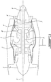
- Figure 1 shows an example gas turbine engine having in serial flow communication a fan 1 through which ambient air is propelled, a compressor section 2 for pressurizing the air, a combustor 3 in which the compressed air is mixed with fuel and ignited for generating an annular flow of hot combustion gases, and a turbine section 4 for extracting energy from the combustion gases.
- the fan 1, the compressor section 2 and the turbine section 4 are rotatable about a central rotation axis 5.
- FIGS. 1 and 2 show an axial sectional view of an exemplary bearing assembly for supporting the rear end of the low pressure shaft 7.
- the first or forward end of the low pressure shaft 7 is supported with other bearings (not shown) located aft of the fan 1.
- the illustrated example of the rear bearing assembly comprises axially spaced-apart bearings 8 and 9 (two in the illustrated example) housed in a bearing housing 25 disposed downstream of the turbine section 4. Struts (not shown) or the like may be provided to transfer loads from the bearing housing 25 to an outer engine casing 10.
- oil may be supplied to the bearing housing 25 of bearings 8, 9 via a single oil inlet and scavenged via a single oil outlet.
- a single oil inlet When multiple axially spaced apart bearings are located within a bearing housing, ensuring adequate oil supply and oil circulation to each bearing from a single inlet may require multiple oil channels or conduits within the bearing housing which has limited space available.
- any excess oil trapped within the bearing housing may be cooked or overheated, by convective ambient heat absorbed (i.e. soak back) by the bearing housing from the surrounding hot gas path components. Accordingly, providing adequate oil to multiple bearings may be challenging. Indeed, excess oil represents a weight penalty, adequate distribution of oil within a confined space can be difficult, and residual oil that has been cooked or overheated on engine shutdown has a reduced service life.
- the first or forward bearing 8 is axially spaced from the second or rearward bearing 9 on the low pressure shaft 7.
- Each bearing (forward bearing 8 and rearward bearing 9) has an inner race 11, 12 (respectively) disposed on the low pressure shaft 7 and an outer race 15, 16 (respectively).
- a ring of bearing elements such as cylindrical rollers 13 engage the inner race 11 and the outer race 15 of the forward bearing 8 shown.
- the exemplary bearing assembly further comprises a bearing mounting sleeve 17 having inner sleeve surfaces 18, 19 respectively engaging the outer race 15 of the forward bearing 8 and the outer race 16 of the rearward bearing 9.
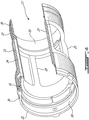
- the bearing mounting sleeve 17 has an outer sleeve surface 20 best seen in Figure 4 .
- the bearing mounting sleeve 17 is a generally cylindrical hollow tube.
- the bearing mounting sleeve 17 comprises a first or forward ring 21 and a second or rearward ring 22 joined together with a plurality of circumferentially spaced-apart axial struts 23. At least one strut 23 includes an axial sleeve oil passage 24.
- Figures 6-7 show the sleeve oil passage 24 and the supply of oil indicated with arrows.
- a bearing housing 25 surrounds an enclosed inner chamber 26 to contain the lubricating oil and support the bearings 8, 9.
- the bearing housing 25 includes an inner bearing support 27 that supports and engages the outer sleeve surface 20 of the bearing mounting sleeve 17.
- the bearing housing 25 has a housing oil inlet 28 ( Fig. 2 ) in fluid communication with the enclosed inner chamber 26 of the bearing housing 25.
- the bearing housing 25 also has a housing oil drain (not shown) in a lower area.
- the engine oil circulating system oil pump, oil filter, oil cooler) supplies pressurized oil to the housing oil inlet 28 and drains spent oil from the housing oil drain.
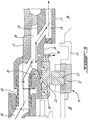
- Figures 5 and 6 show the housing oil inlet 28 and means by which oil is directed to the sleeve oil passage 24 of the bearing mounting sleeve 17.
- the inner bearing support 27 of the bearing housing 25 includes an oil distribution plenum 39 disposed between the housing oil inlet 28 and the forward oil outlets, namely a radially directed oil scoop nozzle 30 ( Fig. 6 ) and an oil damper inlet 31, defined in the forward ring 21 of the bearing mounting sleeve 17.
- the radially directed oil scoop nozzle 30 sprays oil toward a rotating oil scoop 32 that flings oil within the bearing housing 25.
- the oil scoop 32 is provided on the shaft 7 adjacent bearing 8.
- the oil damper inlet 31 directs oil into an oil damper chamber 33 defined between axially spaced apart annular seals 34 engaging the outer race 15 of the forward bearing 8.
- the operation of the oil damper chamber 33 and seals 34 provide a radial dampening of bearing movement.
- the coupling conduit 38 includes a short tube with external spherical seal end surfaces for connecting to sockets of the inner bearing support 27 and the secondary supply conduit 36 fed by the housing oil inlet 28.
- the oil distribution plenum 39 Downstream from the coupling conduit 38 is the oil distribution plenum 39.
- the oil distribution plenum 39 is defined between the inner bearing support 27 and the bearing mounting sleeve 17 as an annular recess fluidly connected to coupling conduit 38.
- the oil flow from the oil distribution plenum 39 lubricates the forward bearing 8 via the radially directed oil scoop nozzle 30, pressurizes the oil filled oil damper chamber 33, and conveys oil toward the rearward bearing 9 via the sleeve oil passage 24 in the bearing mounting sleeve 17.
- the oil distribution plenum 39 could also supply oil to a side nozzle directed radially and axially at an angle toward the forward bearing 8.
- Various oil circuitries are contemplated.
- the axially extending sleeve oil passage 24 in the bearing mounting sleeve 17 is in fluid communication with the housing oil inlet 28 (see Fig. 5 ) via plenum 39.
- the bearing mounting sleeve 17 has a first or forward outlet (e.g. the radially directed oil scoop nozzle 30 and the oil damper inlet 31) in the vicinity of the forward bearing 8 and the sleeve oil passage 24 has at least one second or rearward outlet in the vicinity of the rearward bearing 9.
- the rearward outlet of the sleeve oil passage 24 shows three oil outlets.
- the rearward outlet could include a radially directed oil scoop nozzle, although that option is not shown in the illustrated embodiment.
- Figure 7 shows three outlets namely: two side nozzles 40, 41 directed radially and axially toward the rearward bearing 9; and an oil damper inlet 42.
- the oil damper inlet 42 is directed into an oil damper chamber 43 defined between axially spaced apart annular seals 44, 45 engaging the outer race 16 of the rearward bearing 9.
- the sleeve oil passage 24 or multiple passages provide sufficient oil distribution to the rearward bearing 9 from a single housing oil inlet 28.
- the forward outlets 30, 31 receive oil flow from the oil distribution plenum 39 and the housing oil inlet 28 via the coupling conduit 38 and supply conduits 35, 36.
- the forward outlets 30, 31 could be arranged to receive oil from the sleeve oil passage 24 if desired, however the example illustrated supplies the radially directed oil scoop nozzle 30 and the oil damper inlet 31 directly from the oil distribution plenum 39.
- the above described components provide a method of supplying oil to the forward bearing 8 and the rearward bearing 9 within the bearing housing 25 for supporting the low pressure shaft 7.
- the sequence of assembly is as follows.
- the inner race 11 of the forward bearing 8 and the inner race 12 of the rearward bearing 9 are assembled on the low pressure shaft 7 with the rearward bearing 9 axially spaced from the forward bearing 8.
- the inner sleeve surfaces 18, 19 of the bearing mounting sleeve 17 are respectively assembled on the outer race 15 of the forward bearing 8 and on the outer race 16 the rearward bearing 9.
- the outer sleeve surface 20 of the bearing mounting sleeve 17 is assembled to the inner bearing support 27 of the bearing housing 25 within the enclosed chamber 26.
- the housing oil inlet 28 and the housing oil drain (not shown) of the bearing housing 25 are in fluid communication with the enclosed chamber 26 and in fluid communication with the engine oil circulating system.
- Oil is provided under pressure to the axially extending sleeve oil passage 24 of the bearing mounting sleeve 17 in fluid communication with the housing oil inlet 28. Oil is supplied to the forward bearing 8 to one of more forward outlets (30, 31) in the vicinity of the forward bearing 8 from the oil distribution plenum 39. Oil is supplied to the rearward bearing 9 via the sleeve oil passage 24 to at least one rearward outlet (40, 41, 42) in the vicinity of the rearward bearing 9.
- a bearing housing having a dual bearing mounting sleeve that has integrated oil distribution channels distributing lubricating oil from a single oil inlet to dual bearings.
- the bearing mounting sleeve 17 with integral lubrication passages 24 allows all bearings (8, 9) to be supplied with oil from a single inlet 28 using a single compact element (mounting sleeve 17).
- the axial lubrication passages 24 can be tapped into at various locations and orientations to provide outlets (33, 42) or oil jets (30, 40, 41) at any angle or axial position desired.
- Oil jets can be oriented at side surfaces of the bearings, can be oriented radially toward oil scoops or can inject oil into sealed oil dampers surrounding the outer race of the bearings.
- bearing mounting sleeve 17 allows for preassembly of the outer races of multiple bearings 8, 9 in a sleeve 17 that is inserted together into the bearing support 27. Oil cooking due to soak back or heat convection can be reduced since the oil is conveyed through integral lubrication passages 24 in the internal bearing mounting sleeve 17 rather than in the external bearing housing 25 itself. A more compact and less costly oil distribution system within the bearing housing 25 can be provided to multiple bearings 8,9 accordingly.
Landscapes
- Engineering & Computer Science (AREA)
- General Engineering & Computer Science (AREA)
- Mechanical Engineering (AREA)
- Rolling Contact Bearings (AREA)
Abstract
Description
- The invention generally relates to bearings and, more particularly, to bearing lubrication.
- Gas turbine engines have rotors including shafts rotatably mounted on bearings contained within bearing housings. Each bearing housing encloses bearings in a bearing cavity that receives oil via an oil supply conduit for cooling and lubricating the bearings. Oil is scavenged from the bearing housing and drawn through an oil pump, oil cooler and oil filter before recirculating to the bearing housing.
- Providing adequate oil to multiple bearings is not a simple matter of supplying more volume of oil to the bearing housing. Excess oil represents a weight penalty, adequate distribution of oil within a confined space can be difficult, and residual oil that has been cooked or overheated on engine shutdown has a reduced service life. Improvement is thus desirable.
- According to an aspect of the present invention, there is a bearing assembly for supporting a shaft rotating on an axis, the bearing assembly comprising: a first bearing axially spaced from a second bearing, each bearing having an inner race disposed on the shaft and having an outer race; a bearing mounting sleeve having an outer sleeve surface and having inner sleeve surface engaging the outer race of the first bearing and the second bearing; and a bearing housing having an enclosed chamber with an inner bearing support engaging the outer sleeve surface of the bearing mounting sleeve, and a housing oil inlet in fluid communication with the enclosed chamber; wherein the bearing mounting sleeve includes an axially extending sleeve oil passage in fluid communication with the housing oil inlet, the bearing mounting sleeve having a first outlet in the vicinity of the first bearing and the sleeve oil passage having a second outlet in the vicinity of the second bearing.
- According to another aspect of the present invention, there is a bearing mounting sleeve for supporting a shaft rotating on an axis, the shaft being rotatably supported by a forward bearing and a rearward bearing axially spaced from the forward bearing, the shaft being surrounded by a bearing housing having an enclosed chamber with an inner bearing support, a housing oil inlet being in fluid communication with the enclosed chamber, the bearing mounting sleeve comprising: an outer sleeve surface engageable with the inner bearing support of the bearing housing; an inner sleeve surface engageable with the forward bearing and the rearward bearing; a forward outlet in a vicinity of the forward bearing connectable in fluid communication with the housing oil inlet; and an axially extending sleeve oil passage connectable in fluid communication with the housing oil inlet, the axially extending sleeve oil passage having a rearward outlet in a vicinity of the rearward bearing.
- According to another aspect of the present invention, there is a method of providing oil to a dual bearing assembly comprising first and second bearings mounted within a bearing housing having an oil inlet in fluid communication with a chamber, the method comprising: assembling the first and second bearings in a bearing mounting sleeve; assembling the bearing mounting sleeve inside the bearing housing, fluidly connecting a sleeve oil passage extending through the bearing mounting sleeve to the oil inlet of the bearing housing; supplying oil to the first bearing via the oil inlet of the bearing housing to a first outlet in a vicinity of the first bearing; and supplying oil to the second bearing via the sleeve oil passage to a second outlet in a vicinity of the second bearing
- Further details of these and other aspects of the subject matter of this application will be apparent from the detailed description included below and the drawings.
-
-
Figure 1 shows an axial cross-section view of an example turbofan gas turbine engine, having low pressure shaft with a forward fan and a pair of bearing in a rearward bearing housing within the exhaust cone. -
Figure 2 is a partial axial cross-section view through the bearing housing, a bearing mounting sleeve, a forward bearing, a rearward bearing and the low pressure shaft, in accordance with the present description. -
Figure 3 is an axial view along line 3-3 ofFigure 2 . -
Figure 4 is an isometric partial cutaway view of the bearing mounting sleeve comprising forward ring, rearward ring and four axial struts with interior oil passages. -
Figure 5 is a partial axial sectional view of the bearing housing oil inlet. -
Figure 6 is a partial axial sectional view of the forward bearing. -
Figure 7 is a partial axial sectional view of the rearward bearing. -
Figure 1 shows an example gas turbine engine having in serial flow communication a fan 1 through which ambient air is propelled, acompressor section 2 for pressurizing the air, acombustor 3 in which the compressed air is mixed with fuel and ignited for generating an annular flow of hot combustion gases, and aturbine section 4 for extracting energy from the combustion gases. The fan 1, thecompressor section 2 and theturbine section 4 are rotatable about acentral rotation axis 5. - The fan 1,
compressor section 2 andturbine section 4 have rotating components which can be mounted on multiple coaxial high pressure shaft 6 and low pressure shaft 7 that rotate concentrically around thecentral axis 5.Figures 1 and2 show an axial sectional view of an exemplary bearing assembly for supporting the rear end of the low pressure shaft 7. The first or forward end of the low pressure shaft 7 is supported with other bearings (not shown) located aft of the fan 1. The illustrated example of the rear bearing assembly comprises axially spaced-apart bearings 8 and 9 (two in the illustrated example) housed in a bearinghousing 25 disposed downstream of theturbine section 4. Struts (not shown) or the like may be provided to transfer loads from the bearinghousing 25 to anouter engine casing 10. - Due to limited space and access, oil may be supplied to the bearing
housing 25 ofbearings - On engine shutdown, any excess oil trapped within the bearing housing may be cooked or overheated, by convective ambient heat absorbed (i.e. soak back) by the bearing housing from the surrounding hot gas path components. Accordingly, providing adequate oil to multiple bearings may be challenging. Indeed, excess oil represents a weight penalty, adequate distribution of oil within a confined space can be difficult, and residual oil that has been cooked or overheated on engine shutdown has a reduced service life.
- Referring to
Figures 2 ,6 to 7 , the first or forward bearing 8 is axially spaced from the second or rearward bearing 9 on the low pressure shaft 7. Each bearing (forward bearing 8 and rearward bearing 9) has aninner race 11, 12 (respectively) disposed on the low pressure shaft 7 and anouter race 15, 16 (respectively). As seen inFigure 3 , a ring of bearing elements such ascylindrical rollers 13 engage theinner race 11 and theouter race 15 of the forward bearing 8 shown. - Referring concurrently to
Figures 4 ,6-7 , it can be seen that the exemplary bearing assembly further comprises abearing mounting sleeve 17 havinginner sleeve surfaces outer race 15 of theforward bearing 8 and theouter race 16 of the rearward bearing 9. Thebearing mounting sleeve 17 has anouter sleeve surface 20 best seen inFigure 4 . In the example shown inFigure 4 , thebearing mounting sleeve 17 is a generally cylindrical hollow tube. Thebearing mounting sleeve 17 comprises a first orforward ring 21 and a second orrearward ring 22 joined together with a plurality of circumferentially spaced-apartaxial struts 23. At least onestrut 23 includes an axialsleeve oil passage 24.Figures 6-7 show thesleeve oil passage 24 and the supply of oil indicated with arrows. - Referring to
Figures 2 ,6-7 , a bearinghousing 25 surrounds an enclosedinner chamber 26 to contain the lubricating oil and support thebearings housing 25 includes aninner bearing support 27 that supports and engages theouter sleeve surface 20 of thebearing mounting sleeve 17. The bearinghousing 25 has a housing oil inlet 28 (Fig. 2 ) in fluid communication with the enclosedinner chamber 26 of the bearinghousing 25. The bearinghousing 25 also has a housing oil drain (not shown) in a lower area. The engine oil circulating system (oil pump, oil filter, oil cooler) supplies pressurized oil to thehousing oil inlet 28 and drains spent oil from the housing oil drain. -
Figures 5 and6 show thehousing oil inlet 28 and means by which oil is directed to thesleeve oil passage 24 of thebearing mounting sleeve 17. Theinner bearing support 27 of the bearinghousing 25 includes anoil distribution plenum 39 disposed between thehousing oil inlet 28 and the forward oil outlets, namely a radially directed oil scoop nozzle 30 (Fig. 6 ) and anoil damper inlet 31, defined in theforward ring 21 of thebearing mounting sleeve 17. As best seen inFigure 6 , the radially directedoil scoop nozzle 30 sprays oil toward a rotatingoil scoop 32 that flings oil within the bearinghousing 25. Theoil scoop 32 is provided on the shaft 7 adjacent bearing 8. The oil damper inlet 31 directs oil into anoil damper chamber 33 defined between axially spaced apartannular seals 34 engaging theouter race 15 of theforward bearing 8. The operation of theoil damper chamber 33 andseals 34 provide a radial dampening of bearing movement. - Referring to
Figure 5 , when oil enters thehousing oil inlet 28 of thebearing housing 25, the oil flows into aprimary supply conduit 35 and asecondary supply conduit 36 that may be drilled into the bearinghousing 25 and sealed with aplug weld 37. Since the inner bearing support 27 flexes and moves relative to the stationary outer portions of the bearing housing 25 (housing oil inlet 28 andconduits 35, 36) acoupling conduit 38 provides flexibility between theinner bearing support 27 and thehousing oil inlet 28. In the example illustrated (Figs. 5-6 ), thecoupling conduit 38 includes a short tube with external spherical seal end surfaces for connecting to sockets of theinner bearing support 27 and thesecondary supply conduit 36 fed by thehousing oil inlet 28. Downstream from thecoupling conduit 38 is theoil distribution plenum 39. In the example shown, theoil distribution plenum 39 is defined between theinner bearing support 27 and thebearing mounting sleeve 17 as an annular recess fluidly connected tocoupling conduit 38. - Referring to
Figures 6-7 , the oil flow from theoil distribution plenum 39 lubricates the forward bearing 8 via the radially directedoil scoop nozzle 30, pressurizes the oil filledoil damper chamber 33, and conveys oil toward the rearward bearing 9 via thesleeve oil passage 24 in thebearing mounting sleeve 17. Although not shown inFigure 6 , theoil distribution plenum 39 could also supply oil to a side nozzle directed radially and axially at an angle toward theforward bearing 8. Various oil circuitries are contemplated. - Referring to
Figures 4 ,6-7 , the axially extendingsleeve oil passage 24 in thebearing mounting sleeve 17 is in fluid communication with the housing oil inlet 28 (seeFig. 5 ) viaplenum 39. Thebearing mounting sleeve 17 has a first or forward outlet (e.g. the radially directedoil scoop nozzle 30 and the oil damper inlet 31) in the vicinity of the forward bearing 8 and thesleeve oil passage 24 has at least one second or rearward outlet in the vicinity of the rearward bearing 9. - Referring to the example of
Figure 7 , the rearward outlet of thesleeve oil passage 24 shows three oil outlets. As described in relating to the forward outlet near theforward bearing 8, the rearward outlet could include a radially directed oil scoop nozzle, although that option is not shown in the illustrated embodiment.Figure 7 shows three outlets namely: twoside nozzles rearward bearing 9; and anoil damper inlet 42. Theoil damper inlet 42 is directed into anoil damper chamber 43 defined between axially spaced apartannular seals outer race 16 of therearward bearing 9. Thesleeve oil passage 24 or multiple passages provide sufficient oil distribution to the rearward bearing 9 from a singlehousing oil inlet 28. - As seen in
Figure 6 , theforward outlets oil distribution plenum 39 and thehousing oil inlet 28 via thecoupling conduit 38 andsupply conduits forward outlets sleeve oil passage 24 if desired, however the example illustrated supplies the radially directedoil scoop nozzle 30 and theoil damper inlet 31 directly from theoil distribution plenum 39. - The above described components provide a method of supplying oil to the
forward bearing 8 and therearward bearing 9 within the bearinghousing 25 for supporting the low pressure shaft 7. The sequence of assembly is as follows. - The
inner race 11 of theforward bearing 8 and theinner race 12 of therearward bearing 9 are assembled on the low pressure shaft 7 with therearward bearing 9 axially spaced from theforward bearing 8. The inner sleeve surfaces 18, 19 of thebearing mounting sleeve 17 are respectively assembled on theouter race 15 of theforward bearing 8 and on theouter race 16 therearward bearing 9. Theouter sleeve surface 20 of thebearing mounting sleeve 17 is assembled to theinner bearing support 27 of the bearinghousing 25 within theenclosed chamber 26. Thehousing oil inlet 28 and the housing oil drain (not shown) of the bearinghousing 25 are in fluid communication with theenclosed chamber 26 and in fluid communication with the engine oil circulating system. Oil is provided under pressure to the axially extendingsleeve oil passage 24 of thebearing mounting sleeve 17 in fluid communication with thehousing oil inlet 28. Oil is supplied to theforward bearing 8 to one of more forward outlets (30, 31) in the vicinity of theforward bearing 8 from theoil distribution plenum 39. Oil is supplied to therearward bearing 9 via thesleeve oil passage 24 to at least one rearward outlet (40, 41, 42) in the vicinity of therearward bearing 9. - According to some embodiments, there is provided a bearing housing having a dual bearing mounting sleeve that has integrated oil distribution channels distributing lubricating oil from a single oil inlet to dual bearings.
- According to some embodiment, the
bearing mounting sleeve 17 withintegral lubrication passages 24 allows all bearings (8, 9) to be supplied with oil from asingle inlet 28 using a single compact element (mounting sleeve 17). Theaxial lubrication passages 24 can be tapped into at various locations and orientations to provide outlets (33, 42) or oil jets (30, 40, 41) at any angle or axial position desired. Oil jets can be oriented at side surfaces of the bearings, can be oriented radially toward oil scoops or can inject oil into sealed oil dampers surrounding the outer race of the bearings. The use of abearing mounting sleeve 17 allows for preassembly of the outer races ofmultiple bearings sleeve 17 that is inserted together into the bearingsupport 27. Oil cooking due to soak back or heat convection can be reduced since the oil is conveyed throughintegral lubrication passages 24 in the internalbearing mounting sleeve 17 rather than in theexternal bearing housing 25 itself. A more compact and less costly oil distribution system within the bearinghousing 25 can be provided tomultiple bearings - The embodiments described in this document provide non-limiting examples of possible implementations of the present technology. Upon review of the present disclosure, a person of ordinary skill in the art will recognize that changes may be made to the embodiments described herein without departing from the scope of the present technology. For instance, while the bearing assembly has been exemplified as a rear bearing assembly of a low pressure shaft, it is understood that it could be applied to other bearing assemblies of other components. Yet further modifications could be implemented by a person of ordinary skill in the art in view of the present disclosure, which modifications would be within the scope of the present technology.
Claims (15)
- A bearing assembly for supporting a shaft (7) rotating on an axis (5), the bearing assembly comprising:a first bearing (8) axially spaced from a second bearing (9), each bearing (8, 9) having an inner race (11, 12) and an outer race (15, 16);a bearing mounting sleeve (17) having an outer sleeve surface (20) and an inner sleeve surface (18, 19), the inner sleeve surface (18, 19) engaging the outer race (15, 16) of the first bearing (8) and the second bearing (9); anda bearing housing (25) having an enclosed chamber (26) with an inner bearing support (27) engaging the outer sleeve surface (20) of the bearing mounting sleeve (17), and a housing oil inlet (28) in fluid communication with the enclosed chamber (26), wherein the bearing mounting sleeve (17) includes an axially extending sleeve oil passage (24) in fluid communication with the housing oil inlet (28), the bearing mounting sleeve (17) has a first outlet in the vicinity of the first bearing (8) and the sleeve oil passage (24) has a second outlet in the vicinity of the second bearing (9).
- The bearing assembly according to claim 1, wherein the bearing mounting sleeve (17) comprises a first ring (21) and a second ring (22) joined together with a plurality of axial struts (23), and the sleeve oil passage (24) is disposed within at least one of the plurality of axial struts (23).
- The bearing assembly according to claim 1 or 2, wherein the second outlet of the sleeve oil passage (24) comprises:a radially directed oil scoop nozzle;a side nozzle (40, 41) directed radially and axially toward the second bearing (9); and/oran oil damper inlet (42) directed into an oil damper chamber (43) defined between axially spaced apart annular seals (44, 45) engaging the outer race (16) of the second bearing (9).
- The bearing assembly according to any preceding claim, wherein the first outlet of the bearing mounting sleeve (17) comprises:a radially directed oil scoop nozzle (30);a side nozzle directed radially and axially toward the first bearing (8); and/oran oil damper inlet (31) directed into an oil damper chamber (33) defined between axially spaced apart annular seals (34) engaging the outer race (15) of the first bearing (8).
- The bearing assembly according to any preceding claim, wherein the bearing housing (25) includes an oil distribution plenum (39) disposed between the housing oil inlet (28) and the first outlet.
- The bearing assembly according to claim 5, wherein the oil distribution plenum (39) comprises an annular recess defined between the inner bearing support (27) and the bearing mounting sleeve (17).
- The bearing assembly according to any preceding claim, comprising a coupling conduit (38) between the inner bearing support (27) and the housing oil inlet (28).
- The bearing assembly according to claim 7, wherein the coupling conduit (38) has external spherical seal end surfaces for connecting to sockets of the inner bearing support (27) and the housing oil inlet (28).
- A bearing mounting sleeve (17) for supporting a shaft (7) rotating on an axis (5), the shaft (7) being rotatably supported by a forward bearing (8) and a rearward bearing (9) axially spaced from the forward bearing (8), the shaft (7) being surrounded by a bearing housing (25) having an enclosed chamber (26) with an inner bearing support (27), and a housing oil inlet (28) being in fluid communication with the enclosed chamber (26),
the bearing mounting sleeve (17) comprising:an outer sleeve surface (20) engageable with the inner bearing support (27) of the bearing housing (25);an inner sleeve surface (18, 19) engageable with the forward bearing (8) and the rearward bearing (9);a forward outlet in a vicinity of the forward bearing (8) connectable in fluid communication with the housing oil inlet (28); andan axially extending sleeve oil passage (24) connectable in fluid communication with the housing oil inlet (28), the axially extending sleeve oil passage (24) having a rearward outlet in a vicinity of the rearward bearing (9). - The bearing mounting sleeve (17) according to claim 9, comprising a forward ring (21) and a rearward ring (22) joined together with a plurality of axial struts (23), wherein the sleeve oil passage (24) extends axially through at least one strut (23) of the plurality of axial struts (23).
- The bearing mounting sleeve (17) according to claim 9 or 10, wherein the rearward outlet comprises:a radially directed oil scoop nozzle;a side nozzle (40, 41) directed radially and axially toward the rearward bearing (9); and/oran oil damper inlet (42) directed into an oil damper chamber (43) defined between axially spaced apart annular seals (44, 45) engaging an outer race (16) of the rearward bearing (9).
- The bearing mounting sleeve (17) according to any of claims 9 to 11 wherein the forward outlet comprises:a radially directed oil scoop nozzle (30);a side nozzle directed radially and axially toward the forward bearing (8); and/oran oil damper inlet (31) directed into an oil damper chamber (33) defined between axially spaced apart annular seals (34) engaging an outer race (15) of the forward bearing (8).
- A method of providing oil to a dual bearing assembly comprising first and second bearings (8, 9) mounted within a bearing housing (25) having an oil inlet (28) in fluid communication with a chamber (26), the method comprising:assembling the first and second bearings (8, 9) in a bearing mounting sleeve (17);assembling the bearing mounting sleeve (17) inside the bearing housing (25),fluidly connecting a sleeve oil passage (24) extending through the bearing mounting sleeve (17) to the oil inlet (28) of the bearing housing (25);supplying oil to the first bearing (8) via the oil inlet (28) of the bearing housing (25) to a first outlet in a vicinity of the first bearing (8); andsupplying oil to the second bearing (9) via the sleeve oil passage (24) to a second outlet in a vicinity of the second bearing (9).
- The method according to claim 13, wherein supplying oil to the second bearing (9) comprises supplying oil via:a radially directed oil scoop nozzle;a side nozzle (40, 41) directed radially and axially toward the second bearing (9); and/oran oil damper inlet (42) directed into an oil damper chamber (43) defined between axially spaced apart annular seals (44, 45) engaging an outer race (16) of the second bearing (9).
- The method according to claim 13 or 14, wherein supplying oil to the first bearing (8) comprises supplying oil via:a radially directed oil scoop nozzle (30);a side nozzle directed radially and axially toward the first bearing (9); and/oran oil damper inlet (31) directed into an oil damper chamber (33) defined between axially spaced apart annular seals (34) engaging an outer race (15) of the first bearing (8).
Applications Claiming Priority (1)
| Application Number | Priority Date | Filing Date | Title |
|---|---|---|---|
| US16/829,023 US11268573B2 (en) | 2020-03-25 | 2020-03-25 | Bearing housing oil intake to supply dual bearing structure |
Publications (2)
| Publication Number | Publication Date |
|---|---|
| EP3885593A1 true EP3885593A1 (en) | 2021-09-29 |
| EP3885593B1 EP3885593B1 (en) | 2023-07-19 |
Family
ID=75203196
Family Applications (1)
| Application Number | Title | Priority Date | Filing Date |
|---|---|---|---|
| EP21164577.5A Active EP3885593B1 (en) | 2020-03-25 | 2021-03-24 | Bearing housing oil intake to supply dual bearing structure |
Country Status (3)
| Country | Link |
|---|---|
| US (1) | US11268573B2 (en) |
| EP (1) | EP3885593B1 (en) |
| CA (1) | CA3111919A1 (en) |
Families Citing this family (5)
| Publication number | Priority date | Publication date | Assignee | Title |
|---|---|---|---|---|
| DE102018202494A1 (en) * | 2018-02-19 | 2019-08-22 | MTU Aero Engines AG | STORAGE CHAMBER HOUSING FOR A FLOW MACHINE |
| US12516610B2 (en) * | 2022-11-07 | 2026-01-06 | Rtx Corporation | Oil passage built into bearing compartment spring |
| US20240151266A1 (en) * | 2022-11-07 | 2024-05-09 | Rtx Corporation | Thermal zone cooling in a bearing compartment |
| US12203382B1 (en) | 2023-10-23 | 2025-01-21 | Rtx Corporation | Bearing oil distribution scheme |
| US12601375B2 (en) * | 2024-02-29 | 2026-04-14 | Flowserve Pte. Ltd. | Bearing assembly with internal prime-retaining pressurized lubrication system |
Citations (4)
| Publication number | Priority date | Publication date | Assignee | Title |
|---|---|---|---|---|
| FR1093768A (en) * | 1953-02-23 | 1955-05-09 | Maschf Augsburg Nuernberg Ag | Elastic mounting of a rotating shaft in bearings |
| US4789253A (en) * | 1987-01-30 | 1988-12-06 | Bbc Brown Boveri Ag | Axially pre-tensioned rolling contact bearing arrangement |
| US5388917A (en) * | 1992-10-14 | 1995-02-14 | Ntn Corporation | Spindle unit |
| WO2019058051A1 (en) * | 2017-09-22 | 2019-03-28 | Safran Transmission Systems | Device for lubricating and cooling a turbomachine rolling bearing |
Family Cites Families (11)
| Publication number | Priority date | Publication date | Assignee | Title |
|---|---|---|---|---|
| US3011840A (en) * | 1958-06-23 | 1961-12-05 | Blackburn Engines Ltd | Bearing housings for aligned high speed shafts |
| US4214796A (en) * | 1978-10-19 | 1980-07-29 | General Electric Company | Bearing assembly with multiple squeeze film damper apparatus |
| FR2845138B1 (en) | 2002-10-01 | 2004-12-17 | Snecma Moteurs | BEARING BEARING AMORTIZED WITH OIL |
| FR2876758B1 (en) * | 2004-10-19 | 2008-04-18 | Snecma Moteurs Sa | DEVICE FOR SUPPORTING AND GUIDING A ROTATING SHAFT |
| US7574854B2 (en) * | 2006-01-06 | 2009-08-18 | General Electric Company | Gas turbine engine assembly and methods of assembling same |
| US7857519B2 (en) * | 2007-12-07 | 2010-12-28 | Pratt & Whitney Canada Corp. | Compact bearing support |
| FR2926603B1 (en) * | 2008-01-23 | 2010-03-26 | Snecma | GUIDING A TREE IN A TURBOMACHINE |
| US8517672B2 (en) * | 2010-02-23 | 2013-08-27 | General Electric Company | Epicyclic gearbox |
| JP6218234B2 (en) | 2014-03-28 | 2017-10-25 | 本田技研工業株式会社 | Gas turbine engine bearing lubrication structure |
| US10119459B2 (en) | 2015-10-20 | 2018-11-06 | Borgwarner Inc. | Oil supply conduit through stator lamination stack for electrified turbocharger |
| US9702404B2 (en) * | 2015-10-28 | 2017-07-11 | United Technologies Corporation | Integral centering spring and bearing support and method of supporting multiple damped bearings |
-
2020
- 2020-03-25 US US16/829,023 patent/US11268573B2/en active Active
-
2021
- 2021-03-11 CA CA3111919A patent/CA3111919A1/en active Pending
- 2021-03-24 EP EP21164577.5A patent/EP3885593B1/en active Active
Patent Citations (4)
| Publication number | Priority date | Publication date | Assignee | Title |
|---|---|---|---|---|
| FR1093768A (en) * | 1953-02-23 | 1955-05-09 | Maschf Augsburg Nuernberg Ag | Elastic mounting of a rotating shaft in bearings |
| US4789253A (en) * | 1987-01-30 | 1988-12-06 | Bbc Brown Boveri Ag | Axially pre-tensioned rolling contact bearing arrangement |
| US5388917A (en) * | 1992-10-14 | 1995-02-14 | Ntn Corporation | Spindle unit |
| WO2019058051A1 (en) * | 2017-09-22 | 2019-03-28 | Safran Transmission Systems | Device for lubricating and cooling a turbomachine rolling bearing |
Also Published As
| Publication number | Publication date |
|---|---|
| US11268573B2 (en) | 2022-03-08 |
| EP3885593B1 (en) | 2023-07-19 |
| CA3111919A1 (en) | 2021-09-25 |
| US20210301875A1 (en) | 2021-09-30 |
Similar Documents
| Publication | Publication Date | Title |
|---|---|---|
| EP3885593B1 (en) | Bearing housing oil intake to supply dual bearing structure | |
| US11008941B2 (en) | Sump housing for a gas turbine engine | |
| US10526907B2 (en) | Internally cooled seal runner | |
| JP4256151B2 (en) | Flexible combined double shell bearing housing | |
| EP3073135B1 (en) | Bearing system with bearing damper | |
| EP3396113B1 (en) | Intershaft seal with support linkage | |
| US10001166B2 (en) | Gas distribution labyrinth for bearing pad | |
| GB2420381A (en) | Lubricating system for turbine engine. | |
| CA2563821A1 (en) | Gas turbine engine including a low pressure sump seal buffer source and thermally isolated sump | |
| CN120312356A (en) | Gas bearing seal | |
| US11466590B1 (en) | Mid-turbine frame with intermediary plenum | |
| EP4015852B1 (en) | Bearing housing with slip joint | |
| US11549396B2 (en) | Mid-turbine frame for gas turbine engine | |
| US11365682B1 (en) | Gas turbine engine cooled sump buffer air system | |
| US11108302B2 (en) | Electric generator having a liquid coolant system | |
| US11746699B2 (en) | Gas turbine engine | |
| EP4621192A2 (en) | Bearing oil distribution scheme | |
| US20220186784A1 (en) | Bearing housing and method of making |
Legal Events
| Date | Code | Title | Description |
|---|---|---|---|
| PUAI | Public reference made under article 153(3) epc to a published international application that has entered the european phase |
Free format text: ORIGINAL CODE: 0009012 |
|
| STAA | Information on the status of an ep patent application or granted ep patent |
Free format text: STATUS: THE APPLICATION HAS BEEN PUBLISHED |
|
| AK | Designated contracting states |
Kind code of ref document: A1 Designated state(s): AL AT BE BG CH CY CZ DE DK EE ES FI FR GB GR HR HU IE IS IT LI LT LU LV MC MK MT NL NO PL PT RO RS SE SI SK SM TR |
|
| STAA | Information on the status of an ep patent application or granted ep patent |
Free format text: STATUS: REQUEST FOR EXAMINATION WAS MADE |
|
| 17P | Request for examination filed |
Effective date: 20220329 |
|
| RBV | Designated contracting states (corrected) |
Designated state(s): AL AT BE BG CH CY CZ DE DK EE ES FI FR GB GR HR HU IE IS IT LI LT LU LV MC MK MT NL NO PL PT RO RS SE SI SK SM TR |
|
| GRAP | Despatch of communication of intention to grant a patent |
Free format text: ORIGINAL CODE: EPIDOSNIGR1 |
|
| STAA | Information on the status of an ep patent application or granted ep patent |
Free format text: STATUS: GRANT OF PATENT IS INTENDED |
|
| INTG | Intention to grant announced |
Effective date: 20230202 |
|
| GRAS | Grant fee paid |
Free format text: ORIGINAL CODE: EPIDOSNIGR3 |
|
| GRAA | (expected) grant |
Free format text: ORIGINAL CODE: 0009210 |
|
| STAA | Information on the status of an ep patent application or granted ep patent |
Free format text: STATUS: THE PATENT HAS BEEN GRANTED |
|
| AK | Designated contracting states |
Kind code of ref document: B1 Designated state(s): AL AT BE BG CH CY CZ DE DK EE ES FI FR GB GR HR HU IE IS IT LI LT LU LV MC MK MT NL NO PL PT RO RS SE SI SK SM TR |
|
| REG | Reference to a national code |
Ref country code: GB Ref legal event code: FG4D |
|
| REG | Reference to a national code |
Ref country code: CH Ref legal event code: EP |
|
| REG | Reference to a national code |
Ref country code: DE Ref legal event code: R096 Ref document number: 602021003529 Country of ref document: DE |
|
| REG | Reference to a national code |
Ref country code: IE Ref legal event code: FG4D |
|
| REG | Reference to a national code |
Ref country code: LT Ref legal event code: MG9D |
|
| REG | Reference to a national code |
Ref country code: NL Ref legal event code: MP Effective date: 20230719 |
|
| REG | Reference to a national code |
Ref country code: AT Ref legal event code: MK05 Ref document number: 1589758 Country of ref document: AT Kind code of ref document: T Effective date: 20230719 |
|
| PG25 | Lapsed in a contracting state [announced via postgrant information from national office to epo] |
Ref country code: NL Free format text: LAPSE BECAUSE OF FAILURE TO SUBMIT A TRANSLATION OF THE DESCRIPTION OR TO PAY THE FEE WITHIN THE PRESCRIBED TIME-LIMIT Effective date: 20230719 |
|
| PG25 | Lapsed in a contracting state [announced via postgrant information from national office to epo] |
Ref country code: GR Free format text: LAPSE BECAUSE OF FAILURE TO SUBMIT A TRANSLATION OF THE DESCRIPTION OR TO PAY THE FEE WITHIN THE PRESCRIBED TIME-LIMIT Effective date: 20231020 |
|
| PG25 | Lapsed in a contracting state [announced via postgrant information from national office to epo] |
Ref country code: IS Free format text: LAPSE BECAUSE OF FAILURE TO SUBMIT A TRANSLATION OF THE DESCRIPTION OR TO PAY THE FEE WITHIN THE PRESCRIBED TIME-LIMIT Effective date: 20231119 |
|
| PG25 | Lapsed in a contracting state [announced via postgrant information from national office to epo] |
Ref country code: SE Free format text: LAPSE BECAUSE OF FAILURE TO SUBMIT A TRANSLATION OF THE DESCRIPTION OR TO PAY THE FEE WITHIN THE PRESCRIBED TIME-LIMIT Effective date: 20230719 Ref country code: RS Free format text: LAPSE BECAUSE OF FAILURE TO SUBMIT A TRANSLATION OF THE DESCRIPTION OR TO PAY THE FEE WITHIN THE PRESCRIBED TIME-LIMIT Effective date: 20230719 Ref country code: PT Free format text: LAPSE BECAUSE OF FAILURE TO SUBMIT A TRANSLATION OF THE DESCRIPTION OR TO PAY THE FEE WITHIN THE PRESCRIBED TIME-LIMIT Effective date: 20231120 Ref country code: NO Free format text: LAPSE BECAUSE OF FAILURE TO SUBMIT A TRANSLATION OF THE DESCRIPTION OR TO PAY THE FEE WITHIN THE PRESCRIBED TIME-LIMIT Effective date: 20231019 Ref country code: LV Free format text: LAPSE BECAUSE OF FAILURE TO SUBMIT A TRANSLATION OF THE DESCRIPTION OR TO PAY THE FEE WITHIN THE PRESCRIBED TIME-LIMIT Effective date: 20230719 Ref country code: LT Free format text: LAPSE BECAUSE OF FAILURE TO SUBMIT A TRANSLATION OF THE DESCRIPTION OR TO PAY THE FEE WITHIN THE PRESCRIBED TIME-LIMIT Effective date: 20230719 Ref country code: IS Free format text: LAPSE BECAUSE OF FAILURE TO SUBMIT A TRANSLATION OF THE DESCRIPTION OR TO PAY THE FEE WITHIN THE PRESCRIBED TIME-LIMIT Effective date: 20231119 Ref country code: HR Free format text: LAPSE BECAUSE OF FAILURE TO SUBMIT A TRANSLATION OF THE DESCRIPTION OR TO PAY THE FEE WITHIN THE PRESCRIBED TIME-LIMIT Effective date: 20230719 Ref country code: GR Free format text: LAPSE BECAUSE OF FAILURE TO SUBMIT A TRANSLATION OF THE DESCRIPTION OR TO PAY THE FEE WITHIN THE PRESCRIBED TIME-LIMIT Effective date: 20231020 Ref country code: FI Free format text: LAPSE BECAUSE OF FAILURE TO SUBMIT A TRANSLATION OF THE DESCRIPTION OR TO PAY THE FEE WITHIN THE PRESCRIBED TIME-LIMIT Effective date: 20230719 Ref country code: AT Free format text: LAPSE BECAUSE OF FAILURE TO SUBMIT A TRANSLATION OF THE DESCRIPTION OR TO PAY THE FEE WITHIN THE PRESCRIBED TIME-LIMIT Effective date: 20230719 |
|
| PG25 | Lapsed in a contracting state [announced via postgrant information from national office to epo] |
Ref country code: PL Free format text: LAPSE BECAUSE OF FAILURE TO SUBMIT A TRANSLATION OF THE DESCRIPTION OR TO PAY THE FEE WITHIN THE PRESCRIBED TIME-LIMIT Effective date: 20230719 |
|
| REG | Reference to a national code |
Ref country code: DE Ref legal event code: R097 Ref document number: 602021003529 Country of ref document: DE |
|
| PG25 | Lapsed in a contracting state [announced via postgrant information from national office to epo] |
Ref country code: ES Free format text: LAPSE BECAUSE OF FAILURE TO SUBMIT A TRANSLATION OF THE DESCRIPTION OR TO PAY THE FEE WITHIN THE PRESCRIBED TIME-LIMIT Effective date: 20230719 |
|
| PG25 | Lapsed in a contracting state [announced via postgrant information from national office to epo] |
Ref country code: SM Free format text: LAPSE BECAUSE OF FAILURE TO SUBMIT A TRANSLATION OF THE DESCRIPTION OR TO PAY THE FEE WITHIN THE PRESCRIBED TIME-LIMIT Effective date: 20230719 Ref country code: RO Free format text: LAPSE BECAUSE OF FAILURE TO SUBMIT A TRANSLATION OF THE DESCRIPTION OR TO PAY THE FEE WITHIN THE PRESCRIBED TIME-LIMIT Effective date: 20230719 Ref country code: ES Free format text: LAPSE BECAUSE OF FAILURE TO SUBMIT A TRANSLATION OF THE DESCRIPTION OR TO PAY THE FEE WITHIN THE PRESCRIBED TIME-LIMIT Effective date: 20230719 Ref country code: EE Free format text: LAPSE BECAUSE OF FAILURE TO SUBMIT A TRANSLATION OF THE DESCRIPTION OR TO PAY THE FEE WITHIN THE PRESCRIBED TIME-LIMIT Effective date: 20230719 Ref country code: DK Free format text: LAPSE BECAUSE OF FAILURE TO SUBMIT A TRANSLATION OF THE DESCRIPTION OR TO PAY THE FEE WITHIN THE PRESCRIBED TIME-LIMIT Effective date: 20230719 Ref country code: CZ Free format text: LAPSE BECAUSE OF FAILURE TO SUBMIT A TRANSLATION OF THE DESCRIPTION OR TO PAY THE FEE WITHIN THE PRESCRIBED TIME-LIMIT Effective date: 20230719 Ref country code: SK Free format text: LAPSE BECAUSE OF FAILURE TO SUBMIT A TRANSLATION OF THE DESCRIPTION OR TO PAY THE FEE WITHIN THE PRESCRIBED TIME-LIMIT Effective date: 20230719 |
|
| PLBE | No opposition filed within time limit |
Free format text: ORIGINAL CODE: 0009261 |
|
| STAA | Information on the status of an ep patent application or granted ep patent |
Free format text: STATUS: NO OPPOSITION FILED WITHIN TIME LIMIT |
|
| PG25 | Lapsed in a contracting state [announced via postgrant information from national office to epo] |
Ref country code: IT Free format text: LAPSE BECAUSE OF FAILURE TO SUBMIT A TRANSLATION OF THE DESCRIPTION OR TO PAY THE FEE WITHIN THE PRESCRIBED TIME-LIMIT Effective date: 20230719 |
|
| 26N | No opposition filed |
Effective date: 20240422 |
|
| PG25 | Lapsed in a contracting state [announced via postgrant information from national office to epo] |
Ref country code: SI Free format text: LAPSE BECAUSE OF FAILURE TO SUBMIT A TRANSLATION OF THE DESCRIPTION OR TO PAY THE FEE WITHIN THE PRESCRIBED TIME-LIMIT Effective date: 20230719 |
|
| REG | Reference to a national code |
Ref country code: CH Ref legal event code: PL |
|
| PG25 | Lapsed in a contracting state [announced via postgrant information from national office to epo] |
Ref country code: BG Free format text: LAPSE BECAUSE OF FAILURE TO SUBMIT A TRANSLATION OF THE DESCRIPTION OR TO PAY THE FEE WITHIN THE PRESCRIBED TIME-LIMIT Effective date: 20230719 |
|
| PG25 | Lapsed in a contracting state [announced via postgrant information from national office to epo] |
Ref country code: LU Free format text: LAPSE BECAUSE OF NON-PAYMENT OF DUE FEES Effective date: 20240324 |
|
| PG25 | Lapsed in a contracting state [announced via postgrant information from national office to epo] |
Ref country code: MC Free format text: LAPSE BECAUSE OF FAILURE TO SUBMIT A TRANSLATION OF THE DESCRIPTION OR TO PAY THE FEE WITHIN THE PRESCRIBED TIME-LIMIT Effective date: 20230719 |
|
| PG25 | Lapsed in a contracting state [announced via postgrant information from national office to epo] |
Ref country code: MC Free format text: LAPSE BECAUSE OF FAILURE TO SUBMIT A TRANSLATION OF THE DESCRIPTION OR TO PAY THE FEE WITHIN THE PRESCRIBED TIME-LIMIT Effective date: 20230719 Ref country code: LU Free format text: LAPSE BECAUSE OF NON-PAYMENT OF DUE FEES Effective date: 20240324 Ref country code: BG Free format text: LAPSE BECAUSE OF FAILURE TO SUBMIT A TRANSLATION OF THE DESCRIPTION OR TO PAY THE FEE WITHIN THE PRESCRIBED TIME-LIMIT Effective date: 20230719 |
|
| REG | Reference to a national code |
Ref country code: BE Ref legal event code: MM Effective date: 20240331 |
|
| PG25 | Lapsed in a contracting state [announced via postgrant information from national office to epo] |
Ref country code: BE Free format text: LAPSE BECAUSE OF NON-PAYMENT OF DUE FEES Effective date: 20240331 |
|
| PG25 | Lapsed in a contracting state [announced via postgrant information from national office to epo] |
Ref country code: IE Free format text: LAPSE BECAUSE OF NON-PAYMENT OF DUE FEES Effective date: 20240324 |
|
| PG25 | Lapsed in a contracting state [announced via postgrant information from national office to epo] |
Ref country code: IE Free format text: LAPSE BECAUSE OF NON-PAYMENT OF DUE FEES Effective date: 20240324 Ref country code: BE Free format text: LAPSE BECAUSE OF NON-PAYMENT OF DUE FEES Effective date: 20240331 Ref country code: CH Free format text: LAPSE BECAUSE OF NON-PAYMENT OF DUE FEES Effective date: 20240331 |
|
| PG25 | Lapsed in a contracting state [announced via postgrant information from national office to epo] |
Ref country code: CY Free format text: LAPSE BECAUSE OF FAILURE TO SUBMIT A TRANSLATION OF THE DESCRIPTION OR TO PAY THE FEE WITHIN THE PRESCRIBED TIME-LIMIT; INVALID AB INITIO Effective date: 20210324 |
|
| PG25 | Lapsed in a contracting state [announced via postgrant information from national office to epo] |
Ref country code: HU Free format text: LAPSE BECAUSE OF FAILURE TO SUBMIT A TRANSLATION OF THE DESCRIPTION OR TO PAY THE FEE WITHIN THE PRESCRIBED TIME-LIMIT; INVALID AB INITIO Effective date: 20210324 |
|
| PG25 | Lapsed in a contracting state [announced via postgrant information from national office to epo] |
Ref country code: TR Free format text: LAPSE BECAUSE OF FAILURE TO SUBMIT A TRANSLATION OF THE DESCRIPTION OR TO PAY THE FEE WITHIN THE PRESCRIBED TIME-LIMIT Effective date: 20230719 |
|
| P01 | Opt-out of the competence of the unified patent court (upc) registered |
Free format text: CASE NUMBER: UPC_APP_0000176_3885593/2026 Effective date: 20260105 |
|
| PGFP | Annual fee paid to national office [announced via postgrant information from national office to epo] |
Ref country code: GB Payment date: 20260220 Year of fee payment: 6 |
|
| PGFP | Annual fee paid to national office [announced via postgrant information from national office to epo] |
Ref country code: DE Payment date: 20260219 Year of fee payment: 6 |
|
| PGFP | Annual fee paid to national office [announced via postgrant information from national office to epo] |
Ref country code: FR Payment date: 20260219 Year of fee payment: 6 |