EP3885584A1 - Pressure-booster output stabilizer - Google Patents
Pressure-booster output stabilizer Download PDFInfo
- Publication number
- EP3885584A1 EP3885584A1 EP21164460.4A EP21164460A EP3885584A1 EP 3885584 A1 EP3885584 A1 EP 3885584A1 EP 21164460 A EP21164460 A EP 21164460A EP 3885584 A1 EP3885584 A1 EP 3885584A1
- Authority
- EP
- European Patent Office
- Prior art keywords
- pressure
- chamber
- booster
- piston
- fluid
- Prior art date
- Legal status (The legal status is an assumption and is not a legal conclusion. Google has not performed a legal analysis and makes no representation as to the accuracy of the status listed.)
- Granted
Links
Images





Classifications
-
- F—MECHANICAL ENGINEERING; LIGHTING; HEATING; WEAPONS; BLASTING
- F15—FLUID-PRESSURE ACTUATORS; HYDRAULICS OR PNEUMATICS IN GENERAL
- F15B—SYSTEMS ACTING BY MEANS OF FLUIDS IN GENERAL; FLUID-PRESSURE ACTUATORS, e.g. SERVOMOTORS; DETAILS OF FLUID-PRESSURE SYSTEMS, NOT OTHERWISE PROVIDED FOR
- F15B11/00—Servomotor systems without provision for follow-up action; Circuits therefor
- F15B11/02—Systems essentially incorporating special features for controlling the speed or actuating force of an output member
- F15B11/028—Systems essentially incorporating special features for controlling the speed or actuating force of an output member for controlling the actuating force
- F15B11/032—Systems essentially incorporating special features for controlling the speed or actuating force of an output member for controlling the actuating force by means of fluid-pressure converters
-
- F—MECHANICAL ENGINEERING; LIGHTING; HEATING; WEAPONS; BLASTING
- F15—FLUID-PRESSURE ACTUATORS; HYDRAULICS OR PNEUMATICS IN GENERAL
- F15B—SYSTEMS ACTING BY MEANS OF FLUIDS IN GENERAL; FLUID-PRESSURE ACTUATORS, e.g. SERVOMOTORS; DETAILS OF FLUID-PRESSURE SYSTEMS, NOT OTHERWISE PROVIDED FOR
- F15B11/00—Servomotor systems without provision for follow-up action; Circuits therefor
- F15B11/06—Servomotor systems without provision for follow-up action; Circuits therefor involving features specific to the use of a compressible medium, e.g. air, steam
- F15B11/064—Servomotor systems without provision for follow-up action; Circuits therefor involving features specific to the use of a compressible medium, e.g. air, steam with devices for saving the compressible medium
-
- F—MECHANICAL ENGINEERING; LIGHTING; HEATING; WEAPONS; BLASTING
- F15—FLUID-PRESSURE ACTUATORS; HYDRAULICS OR PNEUMATICS IN GENERAL
- F15B—SYSTEMS ACTING BY MEANS OF FLUIDS IN GENERAL; FLUID-PRESSURE ACTUATORS, e.g. SERVOMOTORS; DETAILS OF FLUID-PRESSURE SYSTEMS, NOT OTHERWISE PROVIDED FOR
- F15B15/00—Fluid-actuated devices for displacing a member from one position to another; Gearing associated therewith
- F15B15/08—Characterised by the construction of the motor unit
- F15B15/14—Characterised by the construction of the motor unit of the straight-cylinder type
-
- F—MECHANICAL ENGINEERING; LIGHTING; HEATING; WEAPONS; BLASTING
- F15—FLUID-PRESSURE ACTUATORS; HYDRAULICS OR PNEUMATICS IN GENERAL
- F15B—SYSTEMS ACTING BY MEANS OF FLUIDS IN GENERAL; FLUID-PRESSURE ACTUATORS, e.g. SERVOMOTORS; DETAILS OF FLUID-PRESSURE SYSTEMS, NOT OTHERWISE PROVIDED FOR
- F15B15/00—Fluid-actuated devices for displacing a member from one position to another; Gearing associated therewith
- F15B15/08—Characterised by the construction of the motor unit
- F15B15/14—Characterised by the construction of the motor unit of the straight-cylinder type
- F15B15/1404—Characterised by the construction of the motor unit of the straight-cylinder type in clusters, e.g. multiple cylinders in one block
-
- F—MECHANICAL ENGINEERING; LIGHTING; HEATING; WEAPONS; BLASTING
- F15—FLUID-PRESSURE ACTUATORS; HYDRAULICS OR PNEUMATICS IN GENERAL
- F15B—SYSTEMS ACTING BY MEANS OF FLUIDS IN GENERAL; FLUID-PRESSURE ACTUATORS, e.g. SERVOMOTORS; DETAILS OF FLUID-PRESSURE SYSTEMS, NOT OTHERWISE PROVIDED FOR
- F15B15/00—Fluid-actuated devices for displacing a member from one position to another; Gearing associated therewith
- F15B15/08—Characterised by the construction of the motor unit
- F15B15/14—Characterised by the construction of the motor unit of the straight-cylinder type
- F15B15/1423—Component parts; Constructional details
- F15B15/1428—Cylinders
-
- F—MECHANICAL ENGINEERING; LIGHTING; HEATING; WEAPONS; BLASTING
- F15—FLUID-PRESSURE ACTUATORS; HYDRAULICS OR PNEUMATICS IN GENERAL
- F15B—SYSTEMS ACTING BY MEANS OF FLUIDS IN GENERAL; FLUID-PRESSURE ACTUATORS, e.g. SERVOMOTORS; DETAILS OF FLUID-PRESSURE SYSTEMS, NOT OTHERWISE PROVIDED FOR
- F15B15/00—Fluid-actuated devices for displacing a member from one position to another; Gearing associated therewith
- F15B15/08—Characterised by the construction of the motor unit
- F15B15/14—Characterised by the construction of the motor unit of the straight-cylinder type
- F15B15/1423—Component parts; Constructional details
- F15B15/1447—Pistons; Piston to piston rod assemblies
-
- F—MECHANICAL ENGINEERING; LIGHTING; HEATING; WEAPONS; BLASTING
- F15—FLUID-PRESSURE ACTUATORS; HYDRAULICS OR PNEUMATICS IN GENERAL
- F15B—SYSTEMS ACTING BY MEANS OF FLUIDS IN GENERAL; FLUID-PRESSURE ACTUATORS, e.g. SERVOMOTORS; DETAILS OF FLUID-PRESSURE SYSTEMS, NOT OTHERWISE PROVIDED FOR
- F15B15/00—Fluid-actuated devices for displacing a member from one position to another; Gearing associated therewith
- F15B15/08—Characterised by the construction of the motor unit
- F15B15/14—Characterised by the construction of the motor unit of the straight-cylinder type
- F15B15/1423—Component parts; Constructional details
- F15B15/1457—Piston rods
-
- F—MECHANICAL ENGINEERING; LIGHTING; HEATING; WEAPONS; BLASTING
- F15—FLUID-PRESSURE ACTUATORS; HYDRAULICS OR PNEUMATICS IN GENERAL
- F15B—SYSTEMS ACTING BY MEANS OF FLUIDS IN GENERAL; FLUID-PRESSURE ACTUATORS, e.g. SERVOMOTORS; DETAILS OF FLUID-PRESSURE SYSTEMS, NOT OTHERWISE PROVIDED FOR
- F15B3/00—Intensifiers or fluid-pressure converters, e.g. pressure exchangers; Conveying pressure from one fluid system to another, without contact between the fluids
-
- F—MECHANICAL ENGINEERING; LIGHTING; HEATING; WEAPONS; BLASTING
- F15—FLUID-PRESSURE ACTUATORS; HYDRAULICS OR PNEUMATICS IN GENERAL
- F15B—SYSTEMS ACTING BY MEANS OF FLUIDS IN GENERAL; FLUID-PRESSURE ACTUATORS, e.g. SERVOMOTORS; DETAILS OF FLUID-PRESSURE SYSTEMS, NOT OTHERWISE PROVIDED FOR
- F15B15/00—Fluid-actuated devices for displacing a member from one position to another; Gearing associated therewith
- F15B15/20—Other details, e.g. assembly with regulating devices
- F15B2015/208—Special fluid pressurisation means, e.g. thermal or electrolytic
-
- F—MECHANICAL ENGINEERING; LIGHTING; HEATING; WEAPONS; BLASTING
- F15—FLUID-PRESSURE ACTUATORS; HYDRAULICS OR PNEUMATICS IN GENERAL
- F15B—SYSTEMS ACTING BY MEANS OF FLUIDS IN GENERAL; FLUID-PRESSURE ACTUATORS, e.g. SERVOMOTORS; DETAILS OF FLUID-PRESSURE SYSTEMS, NOT OTHERWISE PROVIDED FOR
- F15B2201/00—Accumulators
- F15B2201/30—Accumulator separating means
- F15B2201/31—Accumulator separating means having rigid separating means, e.g. pistons
-
- F—MECHANICAL ENGINEERING; LIGHTING; HEATING; WEAPONS; BLASTING
- F15—FLUID-PRESSURE ACTUATORS; HYDRAULICS OR PNEUMATICS IN GENERAL
- F15B—SYSTEMS ACTING BY MEANS OF FLUIDS IN GENERAL; FLUID-PRESSURE ACTUATORS, e.g. SERVOMOTORS; DETAILS OF FLUID-PRESSURE SYSTEMS, NOT OTHERWISE PROVIDED FOR
- F15B2201/00—Accumulators
- F15B2201/30—Accumulator separating means
- F15B2201/32—Accumulator separating means having multiple separating means, e.g. with an auxiliary piston sliding within a main piston, multiple membranes or combinations thereof
-
- F—MECHANICAL ENGINEERING; LIGHTING; HEATING; WEAPONS; BLASTING
- F15—FLUID-PRESSURE ACTUATORS; HYDRAULICS OR PNEUMATICS IN GENERAL
- F15B—SYSTEMS ACTING BY MEANS OF FLUIDS IN GENERAL; FLUID-PRESSURE ACTUATORS, e.g. SERVOMOTORS; DETAILS OF FLUID-PRESSURE SYSTEMS, NOT OTHERWISE PROVIDED FOR
- F15B2211/00—Circuits for servomotor systems
- F15B2211/20—Fluid pressure source, e.g. accumulator or variable axial piston pump
- F15B2211/21—Systems with pressure sources other than pumps, e.g. with a pyrotechnical charge
- F15B2211/214—Systems with pressure sources other than pumps, e.g. with a pyrotechnical charge the pressure sources being hydrotransformers
-
- F—MECHANICAL ENGINEERING; LIGHTING; HEATING; WEAPONS; BLASTING
- F15—FLUID-PRESSURE ACTUATORS; HYDRAULICS OR PNEUMATICS IN GENERAL
- F15B—SYSTEMS ACTING BY MEANS OF FLUIDS IN GENERAL; FLUID-PRESSURE ACTUATORS, e.g. SERVOMOTORS; DETAILS OF FLUID-PRESSURE SYSTEMS, NOT OTHERWISE PROVIDED FOR
- F15B2211/00—Circuits for servomotor systems
- F15B2211/80—Other types of control related to particular problems or conditions
- F15B2211/885—Control specific to the type of fluid, e.g. specific to magnetorheological fluid
- F15B2211/8855—Compressible fluids, e.g. specific to pneumatics
Definitions
- the present invention relates to a pressure-booster output stabilizer combined with a fluid pressure booster.
- Description of the Related Art Conventionally, there has been known a pressure booster that pressure-boosts air of a primary pressure supplied from a compressor and outputs the air at a predetermined secondary pressure.
- Japanese Laid-Open Patent Publication No. 2018-084270 discloses a configuration in which drive cylinders are arranged on both sides of a pressure boosting cylinder.
- the pressure-boosted fluid output from the pressure booster is usually stored in an external tank and used in such a form as to be supplied from the tank to a fluid pressure device.
- the present invention has been devised in view of the circumstances described above, and it is an object of the present invention to provide a pressure-booster output stabilizer capable of outputting the secondary pressure of a pressure booster in a stable condition.
- a pressure-booster output stabilizer is connected to a fluid pressure booster that outputs a predetermined secondary pressure from a primary pressure, and includes: a first cylinder having therein a first chamber and a second chamber separated by a first piston; a second cylinder having therein a third chamber and a fourth chamber separated by a second piston; and a piston rod configured to couple the first piston and the second piston.
- the primary pressure is supplied to the first chamber
- the secondary pressure is supplied to the fourth chamber
- a pressurized fluid is taken out from the fourth chamber.
- the pressurized fluid taken out from the fourth chamber of the second cylinder can be kept at a pressure close to the secondary pressure set by the pressure booster and output at a stable pressure. Further, since the operating speed of the pressure booster can be slowed down, the consumption of the pressurized fluid can be reduced and the life of the pressure booster can be extended.
- the pressure-booster output stabilizer since the pressure-booster output stabilizer according to the present invention has a configuration in which the first piston on which the primary pressure of the pressure booster acts and the second piston on which the secondary pressure of the pressure booster acts are connected, and the pressurized fluid is taken out from a chamber to which the pressurized fluid of the secondary pressure is supplied, the secondary pressure of the pressure booster can be output in a stable condition. In addition, since the operating speed of the pressure booster becomes slower, the consumption of pressurized fluid is reduced and the durability of the pressure booster is enhanced.
- the fluid used is a pressurized fluid such as compressed air.
- the fluid pressure booster (pressure booster) 70 combined with the pressure-booster output stabilizer includes a center body 72, a pair of cylinders 74a and 74b connected respectively to both sides of the center body 72, pistons 76a and 76b sliding in the respective cylinders 74a and 74b, and a rod 78 connecting the pistons 76a and 76b.
- the center body 72 has an inlet port 80, an outlet port 82, and a discharge port 84, and the inlet port 80 is connected to an unillustrated fluid supply source (compressor).
- the cylinders 74a, 74b are divided into inner boost chambers 86a, 86b and outer drive chambers 88a, 88b by pistons 76a, 76b.
- the boost chambers 86a and 86b communicate with the inlet port 80 via inlet check valves 90a and 90b provided in the center body 72, and also communicate with the outlet port 82 via outlet check valves 92a and 92b.
- the drive chambers 88a and 88b are connected to a switching valve 94 installed in the center body 72, and push rods 96a and 96b for switching the switching valve 94 are projected into the boost chambers 86a and 86b, respectively.
- the pressure booster 70 also includes a governor 98 for adjusting the secondary pressure of the fluid at the outlet port 82.
- this pressure booster 70 when the piston 76a moves to the left in FIG. 1 by the pressurized fluid supplied to the first drive chamber 88a via the switching valve 94, the pressurized fluid in the first boost chamber 86a is pressure-boosted, and output from the outlet port 82 through the outlet check valve 92a. During this process, the pressurized fluid in the second drive chamber 88b is discharged from the discharge port 84 via the switching valve 94. Then, when the piston 76a moves and pushes the push rod 96a near a stroke end thereof, the switching valve 94 is changed over, so that the pressurized fluid is supplied to the second drive chamber 88b.
- the piston 76b moves to the right in FIG. 1 , so that the pressurized fluid in the second boost chamber 86b is pressure-boosted, and output from the outlet port 82 through the outlet check valve 92b.
- the pressurized fluid in the first drive chamber 88a is discharged from the discharge port 84 via the switching valve 94.
- the switching valve 94 switches to a state shown in the figure.
- the pressure booster 70 repeats the above series of operations until the pressure of the fluid at the outlet port 82 reaches a set secondary pressure.
- the pressure-booster output stabilizer 10 includes a first cylinder 12 and a second cylinder 14 connected in series.
- the first cylinder 12 has a rectangular parallelepiped first cylinder tube 12a and a circular first piston 12b slidably arranged in a circular cylinder hole formed in the first cylinder tube 12a.
- the second cylinder 14 has a rectangular parallelepiped second cylinder tube 14a and a circular second piston 14b slidably arranged in a circular cylinder hole formed in the second cylinder tube 14a.
- the first piston 12b is connected and fixed to one end side of the piston rod 16 by a first nut 17a, and the second piston 14b is connected and fixed to the other end side of the piston rod 16 by a second nut 17b. Therefore, the first piston 12b and the second piston 14b move together with the piston rod 16 in the axial direction.
- the outside diameter of the first piston 12b is greater than the outside diameter of the second piston 14b.
- a rectangular plate-shaped middle cover 18 is provided between the first cylinder tube 12a and the second cylinder tube 14a.
- a rectangular plate-shaped first end cover 20 is provided on an end side of the first cylinder tube 12a that is farther away from the middle cover 18, whereas a rectangular plate-shaped second end cover 22 is provided on an end side of the second cylinder tube 14a that is farther away from the middle cover 18.
- the assembly formed of the first piston 12b, the second piston 14b, and the piston rod 16 (hereinafter referred to as "piston assembly”) is configured to be able to move between a position where the first piston 12b abuts against the first end cover 20 (see FIG. 5 ) and a position where the first piston 12b abuts against the middle cover 18 (see FIG. 6 ).
- the first cylinder tube 12a is sandwiched and held between the first end cover 20 and the middle cover 18 by four bolts 23a being inserted from the first end cover 20 side and screwed into the middle cover 18.
- the second cylinder tube 14a is sandwiched and held between the second end cover 22 and the middle cover 18 by four bolts 23b being inserted from the second end cover 22 side and screwed into the middle cover 18 ( FIG. 3 ).
- the inside of the cylinder hole of the first cylinder tube 12a is partitioned into a first chamber 24a on the first end cover 20 side and a second chamber 24b on the middle cover 18 side by the first piston 12b.
- the inside of the cylinder hole of the second cylinder tube 14a is partitioned into a third chamber 26a on the middle cover 18 side and a fourth chamber 26b on the second end cover 22 side by the second piston 14b.
- one side surface of the first end cover 20 is formed with a primary pressure supply port 28 connected to the aforementioned fluid supply source.
- the pressurized fluid from the fluid supply source is supplied to the inlet port 80 of the pressure booster 70 and also to the primary pressure supply port 28. Therefore, the pressure of the fluid supplied to the first chamber 24a of the first cylinder 12 via the primary pressure supply port 28 is the same as that of the fluid supplied to the inlet port 80 of the pressure booster 70 (i.e., the primary pressure of the pressure booster 70).
- the middle cover 18 includes, formed on one side surface thereof, a first breathing port 30 that opens to the atmosphere.
- a second breathing port 32 that opens to the atmosphere is formed on the other side surface of the middle cover 18 opposite to the one side surface.
- the second chamber 24b of the first cylinder 12 is opened to the atmosphere through the first breathing port 30, and the third chamber 26a of the second cylinder 14 is opened to the atmosphere through the second breathing port 32
- the second end cover 22 includes, formed on one side surface thereof, a secondary pressure supply port 34 that is connected to the outlet port 82 of the pressure booster 70 by an unillustrated tube.
- the pressurized fluid output from the pressure booster 70 is supplied to the fourth chamber 26b of the second cylinder 14 via the secondary pressure supply port 34.
- the pressure of the fluid at the secondary pressure supply port 34 is the same as the pressure of the fluid at the outlet port 82 of the pressure booster 70 (i.e., the secondary pressure of the pressure booster 70).
- An output port 36 is provided on the other side surface of the second end cover 22 opposite to the one side surface where the secondary pressure supply port 34 is provided, and the pressurized fluid in the fourth chamber 26b of the second cylinder 14 can be taken out from the output port 36 and supplied to an unillustrated fluid pressure device.
- the first end cover 20 is provided with a hollow 20a that allows the primary pressure supply port 28 to communicate with the first chamber 24a of the first cylinder 12 and that is capable of accommodating the first nut 17a therein.
- the second end cover 22 is provided with a hollow 22b that allows the secondary pressure supply port 34 and the output port 36 to communicate with the fourth chamber 26b of the second cylinder 14.
- the pressure of the first chamber 24a that is, the primary pressure of the pressure booster 70
- P 1 the pressure of the fourth chamber 26b at which the forces acting on the piston assembly are balanced
- P 2 ' the pressure of the fourth chamber 26b at which the forces acting on the piston assembly are balanced
- P 2 ' the secondary pressure set by the pressure booster 70 is dented by P 2
- P 2 ' can be determined based on P 1 , the cross-sectional area of the first piston 12b, and the cross-sectional area of the second piston 14b.
- P 2 ' be a value as close to P 2 as possible. Further, P 2 ' needs to be P 2 or lower in order that the volume of the fourth chamber 26b can be restored after the piston assembly has moved until the volume of the fourth chamber 26b is minimized.
- the pressure-booster output stabilizer 10 is basically configured as described above, and its operation will be described below.
- the initial state is assumed such that the pressures of the first to fourth chambers 24a to 26b are all equal to the atmospheric pressure and the piston assembly stands still at the position shown in FIG. 4 .
- the pressure booster 70 is not operating. It is also assumed that the unillustrated flow path connecting the output port 36 and the fluid pressure device is closed by an unillustrated solenoid valve.
- the pressurized fluid is supplied from the fluid supply source to the pressure booster 70 and the pressure-booster output stabilizer 10.
- the pressurized fluid having the primary pressure P 1 is supplied to the inlet port 80 of the pressure booster 70, and at the same time, the pressurized fluid having the primary pressure P 1 is also supplied to the primary pressure supply port 28 of the pressure-booster output stabilizer 10.
- the pressurized fluid is supplied from the primary pressure supply port 28 to the first chamber 24a of the first cylinder 12.
- the piston assembly moves until the first piston 12b abuts against the first end cover 20, and the pressurized fluid having the secondary pressure P 2 set by the pressure booster 70 is stored in the fourth chamber 26b of the second cylinder 14 (see FIG. 5 ).
- the pressurized fluid stored in the fourth chamber 26b is supplied through the output port 36 toward the fluid pressure device.
- the piston assembly to maintain the balance of the forces applied to the piston assembly, moves in such a way that the first piston 12b moves away from the first end cover 20 and the second piston 14b moves close to the second end cover 22.
- the volume of the fourth chamber 26b is reduced to thereby suppress the pressure drop.
- the pressure of the fourth chamber 26b is maintained so as not to fall at least below P 2 '.
- the pressure booster 70 operates, but its operating speed is relatively moderate. In this way, the piston assembly moves to reduce the volume of the fourth chamber 26b.
- the pressurized fluid having the secondary pressure P 2 is replenished to the fourth chamber 26b from the outlet port 82 of the pressure booster 70 and the pressurized fluid is drawn out from the fourth chamber 26b.
- FIG. 7 is a diagram showing the relationship between the pressure and the flow rate of the pressurized fluid taken out, for two pressure boosters having different sizes, each with and without the pressure-booster output stabilizer.
- the horizontal axis represents the flow rate, and the vertical axis represents the pressure.
- a graph of circle points joined with a dotted line shows a case where a small pressure booster is used alone, and a graph of circle points joined with a solid line shows a case where the small pressure booster is used in combination with the pressure-booster output stabilizer.
- a graph of triangular points joined with a dotted line shows a case where a medium-sized pressure booster is used alone
- a graph of triangular points joined with a solid line shows a case where the medium-sized pressure booster is used in combination with the pressure-booster output stabilizer.
- use of the pressure-booster output stabilizer in combination suppresses the pressure drop when the flow rate increases. Further, combined use of the pressure-booster output stabilizer enables even a small pressure booster to have a capacity equivalent to a pressure booster of one size higher.
- the first piston 12b on which the primary pressure of the pressure booster 70 acts and the second piston 14b on which the secondary pressure of the pressure booster 70 acts are coupled, and the pressurized fluid is taken out from the fourth chamber 26b to which (the fluid having) the secondary pressure is supplied.
- the pressurized fluid can be output at a stable pressure close to the secondary pressure of the pressure booster 70.
- the amount of pressure fluid discharged from the discharge port 84 is reduced, whereby it is possible to reduce the consumption of pressure fluid and improve the durability of the pressure booster 70 as well.
- a pressure-booster output stabilizer 40 according to a second embodiment of the present invention will be described.
- the second embodiment is different from the first embodiment in that the pressurized fluid from the fluid supply source is supplied to the first chamber of the first cylinder and also to the third chamber of the second cylinder.
- the second embodiment will also be described as being used in combination with the pressure booster 70 described above in the first embodiment, but the combined pressure booster is not limited to the above-described pressure booster 70.
- the pressure-booster output stabilizer 40 includes a first cylinder 42 and a second cylinder 44 connected in series.
- the first cylinder 42 has a rectangular parallelepiped first cylinder tube 42a and a first piston 42b slidably arranged in a cylinder hole formed in the first cylinder tube 42a.
- the second cylinder 44 has a rectangular parallelepiped second cylinder tube 44a and a second piston 44b slidably arranged in a cylinder hole formed in the second cylinder tube 44a.
- the first piston 42b is fixed to one end side of the piston rod 46, and the second piston 44b is fixed to the other end side of the piston rod 46.
- the first piston 42b and the second piston 44b move together with the piston rod 46 in the axial direction.
- the outside diameter of the first piston 42b is the same as the outside diameter of the second piston 44b.
- a middle cover 48 is provided between the first cylinder tube 42a and the second cylinder tube 44a.
- a first end cover 50 is provided on an end side of the first cylinder tube 42a that is farther away from the middle cover 48, whereas a second end cover 52 is provided on an end side of the second cylinder tube 44a that is farther away from the middle cover 48.
- the pressure booster 70 is attached to the second end cover 52.
- the piston assembly formed of the first piston 42b, the second piston 44b, and the piston rod 46 is configured to be able to move between a position where the first piston 42b abuts against the first end cover 50 and a position where the first piston 42b abuts against the middle cover 48.
- the inside of the cylinder hole of the first cylinder tube 42a is partitioned into a first chamber 54a on the first end cover 50 side and a second chamber 54b on the middle cover 48 side by the first piston 42b.
- the inside of the cylinder hole of the second cylinder tube 44a is partitioned into a third chamber 56a on the middle cover 48 side and a fourth chamber 56b on the second end cover 52 side by the second piston 44b.
- the first end cover 50 is provided with a primary pressure supply first port 58 connected to the fluid supply source
- the middle cover 48 is provided with a primary pressure supply second port 60 connected to the fluid supply source.
- the pressurized fluid from the fluid supply source is supplied to the inlet port 80 of the pressure booster 70, and also to the primary pressure supply first port 58 and the primary pressure supply second port 60. Therefore, the pressure of the fluid supplied to the first chamber 54a of the first cylinder 42 via the primary pressure supply first port 58 and the pressure of the fluid supplied to the third chamber 56a of the second cylinder 44 via the primary pressure supply second port 60, are the same as that of the fluid supplied to the inlet port 80 of the pressure booster 70 (i.e., the primary pressure of the pressure booster 70).
- the middle cover 48 is formed with a breathing port (not shown) that is open to the atmosphere, and the second chamber 54b of the first cylinder 42 is opened to the atmosphere through this breathing port.
- the second end cover 52 is provided with a secondary pressure supply port 62 that is directly connected to the outlet port 82 of the pressure booster 70.
- the pressurized fluid output from the pressure booster 70 is supplied to the fourth chamber 56b of the second cylinder 44 via the secondary pressure supply port 62.
- the pressure of the fluid at the secondary pressure supply port 62 is the same as the pressure of the fluid at the outlet port 82 of the pressure booster 70 (i.e., the secondary pressure of the pressure booster 70).
- the second end cover 52 is provided with an output port 64, and the pressurized fluid in the fourth chamber 56b of the second cylinder 44 can be taken out from the output port 64 and supplied to an unillustrated fluid pressure device.
- the output port 64 is arranged at a position away from the secondary pressure supply port 62.
- the pressure of the first chamber 54a and the third chamber 56a that is, the primary pressure of the pressure booster 70
- P 1 the pressure of the fourth chamber 56b at which the forces acting on the piston assembly are balanced
- P 2 ' the pressure of the fourth chamber 56b at which the forces acting on the piston assembly are balanced
- P 2 ' the secondary pressure set by the pressure booster 70 is dented by P 2
- P 2 ' can be determined based on P 1 , the cross-sectional area of the first piston 42b, the cross-sectional area of the second piston 44b, and the cross-sectional area of the piston rod 46.
- P 2 ' be a value as close to P 2 as possible. Further, P 2 ' needs to be P 2 or lower in order that the volume of the fourth chamber 56b can be restored after the piston assembly has moved until the volume of the fourth chamber 56b is minimized.
- the pressure-booster output stabilizer 40 according to the present embodiment is thus configured, and its operation is the same as that of the pressure-booster output stabilizer 10 described above, so the description is omitted.
- the primary pressure and the secondary pressure of the pressure booster 70 act on the piston assembly, and the pressurized fluid is taken out from the fourth chamber 56b to which (the fluid having) the secondary pressure is supplied. Accordingly, it is possible to output the pressurized fluid at a stable pressure close to the secondary pressure of the pressure booster 70. Further, since the operating speed of the pressure booster 70 is moderate, the amount of pressure fluid discharged from the discharge port 84 is reduced, whereby it is possible to reduce the consumption of pressure fluid and improve the durability of the pressure booster 70 as well.
Landscapes
- Engineering & Computer Science (AREA)
- Physics & Mathematics (AREA)
- Fluid Mechanics (AREA)
- Mechanical Engineering (AREA)
- General Engineering & Computer Science (AREA)
- Supply Devices, Intensifiers, Converters, And Telemotors (AREA)
- Actuator (AREA)
Abstract
Description
- The present invention relates to a pressure-booster output stabilizer combined with a fluid pressure booster. Description of the Related Art:
Conventionally, there has been known a pressure booster that pressure-boosts air of a primary pressure supplied from a compressor and outputs the air at a predetermined secondary pressure. - As a pressure booster of this kind, for example, Japanese Laid-Open Patent Publication No.
2018-084270 - However, when the amount of fluid used in the fluid pressure device greatly exceeds the discharge rate of flow from the pressure booster, the pressurized fluid stored in the tank is rapidly consumed, so that the pressure in the tank drops sharply in a short time. Therefore, it is likely that the fluid with a sufficient pressure becomes unable to be supplied to the fluid pressure device. In addition, there is a concern that the pressure booster is operated at higher speed, resulting in increased consumption of the pressurized fluid, and that the life of the pressure booster is shortened.
- The present invention has been devised in view of the circumstances described above, and it is an object of the present invention to provide a pressure-booster output stabilizer capable of outputting the secondary pressure of a pressure booster in a stable condition.
- A pressure-booster output stabilizer according to the present invention is connected to a fluid pressure booster that outputs a predetermined secondary pressure from a primary pressure, and includes: a first cylinder having therein a first chamber and a second chamber separated by a first piston; a second cylinder having therein a third chamber and a fourth chamber separated by a second piston; and a piston rod configured to couple the first piston and the second piston. In this configuration, the primary pressure is supplied to the first chamber, the secondary pressure is supplied to the fourth chamber, and a pressurized fluid is taken out from the fourth chamber.
- According to the above pressure-booster output stabilizer, the pressurized fluid taken out from the fourth chamber of the second cylinder can be kept at a pressure close to the secondary pressure set by the pressure booster and output at a stable pressure. Further, since the operating speed of the pressure booster can be slowed down, the consumption of the pressurized fluid can be reduced and the life of the pressure booster can be extended.
- Since the pressure-booster output stabilizer according to the present invention has a configuration in which the first piston on which the primary pressure of the pressure booster acts and the second piston on which the secondary pressure of the pressure booster acts are connected, and the pressurized fluid is taken out from a chamber to which the pressurized fluid of the secondary pressure is supplied, the secondary pressure of the pressure booster can be output in a stable condition. In addition, since the operating speed of the pressure booster becomes slower, the consumption of pressurized fluid is reduced and the durability of the pressure booster is enhanced.
- The above and other objects, features and advantages of the present invention will become more apparent from the following description when taken in conjunction with the accompanying drawings in which preferred embodiments of the present invention are shown by way of illustrative example.
-
-
FIG. 1 is a diagram showing an example of a pressure booster combined with the pressure-booster output stabilizer according to the present invention; -
FIG. 2 is a plan view of a pressure-booster output stabilizer according to a first embodiment of the present invention; -
FIG. 3 is a side view of the pressure-booster output stabilizer ofFIG. 2 ; -
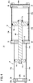
FIG. 4 is a sectional view taken along a line IV-IV of the pressure-booster output stabilizer ofFIG. 2 ; -
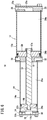
FIG. 5 is a diagram corresponding toFIG. 4 when the pressure-booster output stabilizer ofFIG. 2 is in a predetermined operating position; -
FIG. 6 is a diagram corresponding toFIG. 4 when the pressure-booster output stabilizer ofFIG. 2 is in a different operating position; -
FIG. 7 is a diagram showing the relationships between the flow rate of fluid output from the pressure-booster output stabilizer ofFIG. 2 and the pressure; -
FIG. 8 is a front view of a pressure-booster output stabilizer and a pressure booster according to a second embodiment of the present invention; and -
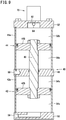
FIG. 9 is a sectional view taken along a line IX-IX of the pressure-booster output stabilizer according to the second embodiment of the present invention. - Now, an example of a fluid pressure booster to be used in combination with a pressure-booster output stabilizer according to the present invention will be described first, and then preferred embodiments of the pressure-booster output stabilizer according to the present invention will be described with reference to the accompanying drawings. The fluid used is a pressurized fluid such as compressed air.
- As illustrated in
FIG. 1 , the fluid pressure booster (pressure booster) 70 combined with the pressure-booster output stabilizer according to the present invention includes acenter body 72, a pair ofcylinders center body 72,pistons respective cylinders rod 78 connecting thepistons center body 72 has aninlet port 80, anoutlet port 82, and adischarge port 84, and theinlet port 80 is connected to an unillustrated fluid supply source (compressor). - The
cylinders inner boost chambers outer drive chambers pistons boost chambers inlet port 80 viainlet check valves center body 72, and also communicate with theoutlet port 82 viaoutlet check valves drive chambers switching valve 94 installed in thecenter body 72, andpush rods switching valve 94 are projected into theboost chambers pressure booster 70 also includes agovernor 98 for adjusting the secondary pressure of the fluid at theoutlet port 82. - In this
pressure booster 70, when thepiston 76a moves to the left inFIG. 1 by the pressurized fluid supplied to thefirst drive chamber 88a via theswitching valve 94, the pressurized fluid in thefirst boost chamber 86a is pressure-boosted, and output from theoutlet port 82 through theoutlet check valve 92a. During this process, the pressurized fluid in thesecond drive chamber 88b is discharged from thedischarge port 84 via theswitching valve 94. Then, when thepiston 76a moves and pushes thepush rod 96a near a stroke end thereof, theswitching valve 94 is changed over, so that the pressurized fluid is supplied to thesecond drive chamber 88b. - As a result, the
piston 76b moves to the right inFIG. 1 , so that the pressurized fluid in thesecond boost chamber 86b is pressure-boosted, and output from theoutlet port 82 through theoutlet check valve 92b. During this process, the pressurized fluid in thefirst drive chamber 88a is discharged from thedischarge port 84 via theswitching valve 94. Then, when thepiston 76b moves and pushes thepush rod 96b near a stroke end thereof, theswitching valve 94 switches to a state shown in the figure. Thepressure booster 70 repeats the above series of operations until the pressure of the fluid at theoutlet port 82 reaches a set secondary pressure. - Next, a pressure-
booster output stabilizer 10 according to the first embodiment of the present invention will be described with reference toFIGS. 2 to 7 . - As shown in
FIG. 4 , the pressure-booster output stabilizer 10 includes afirst cylinder 12 and asecond cylinder 14 connected in series. Thefirst cylinder 12 has a rectangular parallelepipedfirst cylinder tube 12a and a circularfirst piston 12b slidably arranged in a circular cylinder hole formed in thefirst cylinder tube 12a. Thesecond cylinder 14 has a rectangular parallelepipedsecond cylinder tube 14a and acircular second piston 14b slidably arranged in a circular cylinder hole formed in thesecond cylinder tube 14a. - The
first piston 12b is connected and fixed to one end side of thepiston rod 16 by afirst nut 17a, and thesecond piston 14b is connected and fixed to the other end side of thepiston rod 16 by asecond nut 17b. Therefore, thefirst piston 12b and thesecond piston 14b move together with thepiston rod 16 in the axial direction. The outside diameter of thefirst piston 12b is greater than the outside diameter of thesecond piston 14b. - A rectangular plate-
shaped middle cover 18 is provided between thefirst cylinder tube 12a and thesecond cylinder tube 14a. A rectangular plate-shapedfirst end cover 20 is provided on an end side of thefirst cylinder tube 12a that is farther away from themiddle cover 18, whereas a rectangular plate-shapedsecond end cover 22 is provided on an end side of thesecond cylinder tube 14a that is farther away from themiddle cover 18. The assembly formed of thefirst piston 12b, thesecond piston 14b, and the piston rod 16 (hereinafter referred to as "piston assembly") is configured to be able to move between a position where thefirst piston 12b abuts against the first end cover 20 (seeFIG. 5 ) and a position where thefirst piston 12b abuts against the middle cover 18 (seeFIG. 6 ). - The
first cylinder tube 12a is sandwiched and held between thefirst end cover 20 and themiddle cover 18 by fourbolts 23a being inserted from thefirst end cover 20 side and screwed into themiddle cover 18. Thesecond cylinder tube 14a is sandwiched and held between thesecond end cover 22 and themiddle cover 18 by fourbolts 23b being inserted from thesecond end cover 22 side and screwed into the middle cover 18 (FIG. 3 ). - The inside of the cylinder hole of the
first cylinder tube 12a is partitioned into afirst chamber 24a on thefirst end cover 20 side and asecond chamber 24b on themiddle cover 18 side by thefirst piston 12b. The inside of the cylinder hole of thesecond cylinder tube 14a is partitioned into athird chamber 26a on themiddle cover 18 side and afourth chamber 26b on thesecond end cover 22 side by thesecond piston 14b. - As shown in
FIGS. 2 and4 , one side surface of thefirst end cover 20 is formed with a primarypressure supply port 28 connected to the aforementioned fluid supply source. The pressurized fluid from the fluid supply source is supplied to theinlet port 80 of thepressure booster 70 and also to the primarypressure supply port 28. Therefore, the pressure of the fluid supplied to thefirst chamber 24a of thefirst cylinder 12 via the primarypressure supply port 28 is the same as that of the fluid supplied to theinlet port 80 of the pressure booster 70 (i.e., the primary pressure of the pressure booster 70). - The
middle cover 18 includes, formed on one side surface thereof, afirst breathing port 30 that opens to the atmosphere. Asecond breathing port 32 that opens to the atmosphere is formed on the other side surface of themiddle cover 18 opposite to the one side surface. Thesecond chamber 24b of thefirst cylinder 12 is opened to the atmosphere through thefirst breathing port 30, and thethird chamber 26a of thesecond cylinder 14 is opened to the atmosphere through thesecond breathing port 32 - The
second end cover 22 includes, formed on one side surface thereof, a secondarypressure supply port 34 that is connected to theoutlet port 82 of thepressure booster 70 by an unillustrated tube. The pressurized fluid output from thepressure booster 70 is supplied to thefourth chamber 26b of thesecond cylinder 14 via the secondarypressure supply port 34. The pressure of the fluid at the secondarypressure supply port 34 is the same as the pressure of the fluid at theoutlet port 82 of the pressure booster 70 (i.e., the secondary pressure of the pressure booster 70). Anoutput port 36 is provided on the other side surface of thesecond end cover 22 opposite to the one side surface where the secondarypressure supply port 34 is provided, and the pressurized fluid in thefourth chamber 26b of thesecond cylinder 14 can be taken out from theoutput port 36 and supplied to an unillustrated fluid pressure device. - The
first end cover 20 is provided with a hollow 20a that allows the primarypressure supply port 28 to communicate with thefirst chamber 24a of thefirst cylinder 12 and that is capable of accommodating thefirst nut 17a therein. Thesecond end cover 22 is provided with a hollow 22b that allows the secondarypressure supply port 34 and theoutput port 36 to communicate with thefourth chamber 26b of thesecond cylinder 14. - Now, the pressure of the
first chamber 24a, that is, the primary pressure of thepressure booster 70, is denoted by P1, the pressure of thefourth chamber 26b at which the forces acting on the piston assembly are balanced is denoted by P2', and the secondary pressure set by thepressure booster 70 is dented by P2. P2' can be determined based on P1, the cross-sectional area of thefirst piston 12b, and the cross-sectional area of thesecond piston 14b. - In order to maintain the pressure of the fluid taken out from the
fourth chamber 26b at a value close to the secondary pressure P2 set by the pressure booster, it is preferable that P2' be a value as close to P2 as possible. Further, P2' needs to be P2 or lower in order that the volume of thefourth chamber 26b can be restored after the piston assembly has moved until the volume of thefourth chamber 26b is minimized. - The pressure-
booster output stabilizer 10 according to the present embodiment is basically configured as described above, and its operation will be described below. The initial state is assumed such that the pressures of the first tofourth chambers 24a to 26b are all equal to the atmospheric pressure and the piston assembly stands still at the position shown inFIG. 4 . In this initial state, thepressure booster 70 is not operating. It is also assumed that the unillustrated flow path connecting theoutput port 36 and the fluid pressure device is closed by an unillustrated solenoid valve. - By switching an unillustrated switching valve from the above initial state, the pressurized fluid is supplied from the fluid supply source to the
pressure booster 70 and the pressure-booster output stabilizer 10. As a result, the pressurized fluid having the primary pressure P1 is supplied to theinlet port 80 of thepressure booster 70, and at the same time, the pressurized fluid having the primary pressure P1 is also supplied to the primarypressure supply port 28 of the pressure-booster output stabilizer 10. The pressurized fluid is supplied from the primarypressure supply port 28 to thefirst chamber 24a of thefirst cylinder 12. - As (fluid having) the primary pressure is supplied to the
inlet port 80 of thepressure booster 70, operation of thepressure booster 70 is started, and the pressure-boosted fluid is supplied from theoutlet port 82 of thepressure booster 70 toward the secondarypressure supply port 34 of the pressure-booster output stabilizer 10. When thepressure booster 70 operates for a certain time period or more, the pressure in thefourth chamber 26b of thesecond cylinder 14 to which the pressurized fluid has been supplied through the secondarypressure supply port 34 reaches the secondary pressure P2 set by thepressure booster 70, and exceeds the pressure P2' at which the aforementioned piston assembly maintains balance. As a result, the piston assembly moves until thefirst piston 12b abuts against thefirst end cover 20, and the pressurized fluid having the secondary pressure P2 set by thepressure booster 70 is stored in thefourth chamber 26b of the second cylinder 14 (seeFIG. 5 ). - When the flow path connecting the
output port 36 and the fluid pressure device is opened from the state in which the pressurized fluid having the secondary pressure P2 has been stored in thefourth chamber 26b of thesecond cylinder 14, the pressurized fluid stored in thefourth chamber 26b is supplied through theoutput port 36 toward the fluid pressure device. As the pressurized fluid stored in thefourth chamber 26b is taken out from theoutput port 36, the piston assembly, to maintain the balance of the forces applied to the piston assembly, moves in such a way that thefirst piston 12b moves away from thefirst end cover 20 and thesecond piston 14b moves close to thesecond end cover 22. - As a result, the volume of the
fourth chamber 26b is reduced to thereby suppress the pressure drop. The pressure of thefourth chamber 26b is maintained so as not to fall at least below P2'. When the pressure in thefourth chamber 26b falls below the secondary pressure P2 set by thepressure booster 70, thepressure booster 70 operates, but its operating speed is relatively moderate. In this way, the piston assembly moves to reduce the volume of thefourth chamber 26b. Moreover, the pressurized fluid having the secondary pressure P2 is replenished to thefourth chamber 26b from theoutlet port 82 of thepressure booster 70 and the pressurized fluid is drawn out from thefourth chamber 26b. Thus, it is possible to send out the pressurized fluid to the fluid pressure device at a stable pressure. - When the fluid pressure device stops using the pressurized fluid in a state where the
first piston 12b is located at an intermediate position between thefirst end cover 20 and themiddle cover 18, since the pressurized fluid having the secondary pressure P2 is supplied from theoutlet port 82 of thepressure booster 70 to thefourth chamber 26b, the piston assembly moves until thefirst piston 12b abuts against thefirst end cover 20. As a result, the volume of thefourth chamber 26b is restored to the maximum. - When the fluid pressure device has continuously used an extremely large amount of pressurized fluid and the pressurized fluid stored in the
fourth chamber 26b has been rapidly consumed, the piston assembly moves until thefirst piston 12b abuts against themiddle cover 18, so the volume of thefourth chamber 26b is minimized (seeFIG. 6 ). In this case, substantial operation is performed by thepressure booster 70 only, but when the amount of the pressurized fluid used in the fluid pressure device decreases or becomes zero, the volume of thefourth chamber 26b is restored again. -
FIG. 7 is a diagram showing the relationship between the pressure and the flow rate of the pressurized fluid taken out, for two pressure boosters having different sizes, each with and without the pressure-booster output stabilizer. The horizontal axis represents the flow rate, and the vertical axis represents the pressure. A graph of circle points joined with a dotted line shows a case where a small pressure booster is used alone, and a graph of circle points joined with a solid line shows a case where the small pressure booster is used in combination with the pressure-booster output stabilizer. A graph of triangular points joined with a dotted line shows a case where a medium-sized pressure booster is used alone, and a graph of triangular points joined with a solid line shows a case where the medium-sized pressure booster is used in combination with the pressure-booster output stabilizer. - As can be understood from
FIG. 7 , use of the pressure-booster output stabilizer in combination suppresses the pressure drop when the flow rate increases. Further, combined use of the pressure-booster output stabilizer enables even a small pressure booster to have a capacity equivalent to a pressure booster of one size higher. - According to the pressure-
booster output stabilizer 10 of the present embodiment, thefirst piston 12b on which the primary pressure of thepressure booster 70 acts and thesecond piston 14b on which the secondary pressure of thepressure booster 70 acts are coupled, and the pressurized fluid is taken out from thefourth chamber 26b to which (the fluid having) the secondary pressure is supplied. Thus, the pressurized fluid can be output at a stable pressure close to the secondary pressure of thepressure booster 70. Further, since the operating speed of thepressure booster 70 is moderate, the amount of pressure fluid discharged from thedischarge port 84 is reduced, whereby it is possible to reduce the consumption of pressure fluid and improve the durability of thepressure booster 70 as well. - Referring next to
FIGS. 8 and9 , a pressure-booster output stabilizer 40 according to a second embodiment of the present invention will be described. The second embodiment is different from the first embodiment in that the pressurized fluid from the fluid supply source is supplied to the first chamber of the first cylinder and also to the third chamber of the second cylinder. The second embodiment will also be described as being used in combination with thepressure booster 70 described above in the first embodiment, but the combined pressure booster is not limited to the above-describedpressure booster 70. - The pressure-
booster output stabilizer 40 includes afirst cylinder 42 and asecond cylinder 44 connected in series. Thefirst cylinder 42 has a rectangular parallelepipedfirst cylinder tube 42a and afirst piston 42b slidably arranged in a cylinder hole formed in thefirst cylinder tube 42a. Thesecond cylinder 44 has a rectangular parallelepipedsecond cylinder tube 44a and asecond piston 44b slidably arranged in a cylinder hole formed in thesecond cylinder tube 44a. - The
first piston 42b is fixed to one end side of thepiston rod 46, and thesecond piston 44b is fixed to the other end side of thepiston rod 46. Thefirst piston 42b and thesecond piston 44b move together with thepiston rod 46 in the axial direction. The outside diameter of thefirst piston 42b is the same as the outside diameter of thesecond piston 44b. - A
middle cover 48 is provided between thefirst cylinder tube 42a and thesecond cylinder tube 44a. Afirst end cover 50 is provided on an end side of thefirst cylinder tube 42a that is farther away from themiddle cover 48, whereas asecond end cover 52 is provided on an end side of thesecond cylinder tube 44a that is farther away from themiddle cover 48. Thepressure booster 70 is attached to thesecond end cover 52. The piston assembly formed of thefirst piston 42b, thesecond piston 44b, and thepiston rod 46 is configured to be able to move between a position where thefirst piston 42b abuts against thefirst end cover 50 and a position where thefirst piston 42b abuts against themiddle cover 48. - The inside of the cylinder hole of the
first cylinder tube 42a is partitioned into afirst chamber 54a on thefirst end cover 50 side and asecond chamber 54b on themiddle cover 48 side by thefirst piston 42b. The inside of the cylinder hole of thesecond cylinder tube 44a is partitioned into athird chamber 56a on themiddle cover 48 side and afourth chamber 56b on thesecond end cover 52 side by thesecond piston 44b. - The
first end cover 50 is provided with a primary pressure supplyfirst port 58 connected to the fluid supply source, and themiddle cover 48 is provided with a primary pressure supplysecond port 60 connected to the fluid supply source. The pressurized fluid from the fluid supply source is supplied to theinlet port 80 of thepressure booster 70, and also to the primary pressure supplyfirst port 58 and the primary pressure supplysecond port 60. Therefore, the pressure of the fluid supplied to thefirst chamber 54a of thefirst cylinder 42 via the primary pressure supplyfirst port 58 and the pressure of the fluid supplied to thethird chamber 56a of thesecond cylinder 44 via the primary pressure supplysecond port 60, are the same as that of the fluid supplied to theinlet port 80 of the pressure booster 70 (i.e., the primary pressure of the pressure booster 70). - The
middle cover 48 is formed with a breathing port (not shown) that is open to the atmosphere, and thesecond chamber 54b of thefirst cylinder 42 is opened to the atmosphere through this breathing port. Thesecond end cover 52 is provided with a secondarypressure supply port 62 that is directly connected to theoutlet port 82 of thepressure booster 70. The pressurized fluid output from thepressure booster 70 is supplied to thefourth chamber 56b of thesecond cylinder 44 via the secondarypressure supply port 62. The pressure of the fluid at the secondarypressure supply port 62 is the same as the pressure of the fluid at theoutlet port 82 of the pressure booster 70 (i.e., the secondary pressure of the pressure booster 70). Further, thesecond end cover 52 is provided with anoutput port 64, and the pressurized fluid in thefourth chamber 56b of thesecond cylinder 44 can be taken out from theoutput port 64 and supplied to an unillustrated fluid pressure device. Theoutput port 64 is arranged at a position away from the secondarypressure supply port 62. - Here, the pressure of the
first chamber 54a and thethird chamber 56a, that is, the primary pressure of thepressure booster 70, is denoted by P1, the pressure of thefourth chamber 56b at which the forces acting on the piston assembly are balanced is denoted by P2', and the secondary pressure set by thepressure booster 70 is dented by P2. P2' can be determined based on P1, the cross-sectional area of thefirst piston 42b, the cross-sectional area of thesecond piston 44b, and the cross-sectional area of thepiston rod 46. - In order to maintain the pressure of the fluid taken out from the
fourth chamber 56b at a value close to the secondary pressure P2 set by thepressure booster 70, it is preferable that P2' be a value as close to P2 as possible. Further, P2' needs to be P2 or lower in order that the volume of thefourth chamber 56b can be restored after the piston assembly has moved until the volume of thefourth chamber 56b is minimized. - The pressure-
booster output stabilizer 40 according to the present embodiment is thus configured, and its operation is the same as that of the pressure-booster output stabilizer 10 described above, so the description is omitted. - According to the pressure-
booster output stabilizer 40 of the present embodiment, the primary pressure and the secondary pressure of thepressure booster 70 act on the piston assembly, and the pressurized fluid is taken out from thefourth chamber 56b to which (the fluid having) the secondary pressure is supplied. Accordingly, it is possible to output the pressurized fluid at a stable pressure close to the secondary pressure of thepressure booster 70. Further, since the operating speed of thepressure booster 70 is moderate, the amount of pressure fluid discharged from thedischarge port 84 is reduced, whereby it is possible to reduce the consumption of pressure fluid and improve the durability of thepressure booster 70 as well.
Claims (6)
- A pressure-booster output stabilizer (10, 40) connected to a fluid pressure booster (70) that outputs a predetermined secondary pressure from a primary pressure, comprising:a first cylinder (12, 42) having therein a first chamber (24a, 54a) and a second chamber (24b, 54b) separated by a first piston (12b, 42b);a second cylinder (14, 44) having therein a third chamber (26a, 56a) and a fourth chamber (26b, 56b) separated by a second piston (14b, 44b); anda piston rod (16, 46) configured to couple the first piston and the second piston,wherein the primary pressure is supplied to the first chamber, the secondary pressure is supplied to the fourth chamber, and a pressurized fluid is taken out from the fourth chamber.
- The pressure-booster output stabilizer according to claim 1, wherein an outside diameter of the first piston is greater than an outside diameter of the second piston, and the second chamber and the third chamber are opened to atmosphere.
- The pressure-booster output stabilizer according to claim 1, wherein the primary pressure is supplied to the third chamber, and the second chamber is opened to atmosphere.
- The pressure-booster output stabilizer according to claim 3, wherein the second piston has a same outside diameter as the first piston.
- The pressure-booster output stabilizer according to claim 1, wherein:the first cylinder includes a first cylinder tube (12a, 42a) and a first end cover (20, 50);the second cylinder includes a second cylinder tube (14a, 44a) and a second end cover (22, 52); andthe first cylinder tube and the second cylinder tube are connected to each other via a middle cover (18, 48).
- The pressure-booster output stabilizer according to claim 5, wherein:the first end cover is provided with a primary pressure supply port (28) to which the primary pressure is supplied; andthe second end cover is formed with a secondary pressure supply port (34) and an output port (36), and the secondary pressure is supplied to the secondary pressure supply port.
Applications Claiming Priority (1)
| Application Number | Priority Date | Filing Date | Title |
|---|---|---|---|
| JP2020058079A JP7484312B2 (en) | 2020-03-27 | 2020-03-27 | Booster output stabilization device |
Publications (2)
| Publication Number | Publication Date |
|---|---|
| EP3885584A1 true EP3885584A1 (en) | 2021-09-29 |
| EP3885584B1 EP3885584B1 (en) | 2022-11-23 |
Family
ID=75203109
Family Applications (1)
| Application Number | Title | Priority Date | Filing Date |
|---|---|---|---|
| EP21164460.4A Active EP3885584B1 (en) | 2020-03-27 | 2021-03-24 | Assembly with pressure-booster output stabilizer and fluid pressure booster |
Country Status (6)
| Country | Link |
|---|---|
| US (1) | US11661960B2 (en) |
| EP (1) | EP3885584B1 (en) |
| JP (1) | JP7484312B2 (en) |
| KR (1) | KR102915735B1 (en) |
| CN (1) | CN113446273B (en) |
| TW (1) | TWI890764B (en) |
Cited By (1)
| Publication number | Priority date | Publication date | Assignee | Title |
|---|---|---|---|---|
| CN114623117A (en) * | 2022-04-02 | 2022-06-14 | 北京航天试验技术研究所 | Efficient pressurizing device and method for air pressure transmitter |
Citations (4)
| Publication number | Priority date | Publication date | Assignee | Title |
|---|---|---|---|---|
| WO1997042417A1 (en) * | 1996-05-04 | 1997-11-13 | Hydac Technology Gmbh | Device for saving energy |
| WO2011154101A1 (en) * | 2010-06-08 | 2011-12-15 | Hydac Technology Gmbh | Hydraulic system |
| JP2018084270A (en) | 2016-11-22 | 2018-05-31 | Smc株式会社 | Boosting device |
| WO2018198535A1 (en) * | 2017-04-28 | 2018-11-01 | Smc株式会社 | Pressure booster and cylinder apparatus provided with same |
Family Cites Families (11)
| Publication number | Priority date | Publication date | Assignee | Title |
|---|---|---|---|---|
| US3186173A (en) * | 1960-09-15 | 1965-06-01 | American Mach & Foundry | Variable pressure hydraulic system |
| US4051877A (en) * | 1975-10-24 | 1977-10-04 | Nasa | Gas compression apparatus |
| DE2911443C2 (en) * | 1979-03-23 | 1981-03-12 | Bodenseewerk Perkin-Elmer & Co GmbH, 7770 Überlingen | Pressure medium operated pump with variable delivery volume |
| JPS58189801U (en) * | 1982-06-11 | 1983-12-16 | エスエムシ−株式会社 | pressure booster |
| US5435228A (en) * | 1993-07-20 | 1995-07-25 | Pneumatic Energy Inc | Pneumatic transformer |
| JP2955220B2 (en) * | 1995-12-06 | 1999-10-04 | 太陽鉄工株式会社 | In-line pressure booster |
| AU4783996A (en) * | 1996-02-26 | 1997-09-16 | T. Smedegaard A/S | Apparatus for use in a liquid circulation system and method for using said apparatus |
| JP2001115953A (en) | 1999-10-19 | 2001-04-27 | Excel Engineering:Kk | Device for jetting cleaning liquid |
| US20070193797A1 (en) * | 2006-02-22 | 2007-08-23 | Shamis Dmitry A | Pressure booster system |
| JP2009142800A (en) | 2007-12-18 | 2009-07-02 | Smc Corp | Dehumidification system and method for depressurizer piping |
| JP6665985B2 (en) * | 2017-04-07 | 2020-03-13 | Smc株式会社 | Pressure booster |
-
2020
- 2020-03-27 JP JP2020058079A patent/JP7484312B2/en active Active
-
2021
- 2021-03-24 US US17/210,569 patent/US11661960B2/en active Active
- 2021-03-24 EP EP21164460.4A patent/EP3885584B1/en active Active
- 2021-03-25 TW TW110110888A patent/TWI890764B/en active
- 2021-03-26 CN CN202110324048.8A patent/CN113446273B/en active Active
- 2021-03-26 KR KR1020210039631A patent/KR102915735B1/en active Active
Patent Citations (4)
| Publication number | Priority date | Publication date | Assignee | Title |
|---|---|---|---|---|
| WO1997042417A1 (en) * | 1996-05-04 | 1997-11-13 | Hydac Technology Gmbh | Device for saving energy |
| WO2011154101A1 (en) * | 2010-06-08 | 2011-12-15 | Hydac Technology Gmbh | Hydraulic system |
| JP2018084270A (en) | 2016-11-22 | 2018-05-31 | Smc株式会社 | Boosting device |
| WO2018198535A1 (en) * | 2017-04-28 | 2018-11-01 | Smc株式会社 | Pressure booster and cylinder apparatus provided with same |
Cited By (1)
| Publication number | Priority date | Publication date | Assignee | Title |
|---|---|---|---|---|
| CN114623117A (en) * | 2022-04-02 | 2022-06-14 | 北京航天试验技术研究所 | Efficient pressurizing device and method for air pressure transmitter |
Also Published As
| Publication number | Publication date |
|---|---|
| JP7484312B2 (en) | 2024-05-16 |
| US11661960B2 (en) | 2023-05-30 |
| EP3885584B1 (en) | 2022-11-23 |
| CN113446273B (en) | 2025-04-08 |
| JP2021156380A (en) | 2021-10-07 |
| TW202146777A (en) | 2021-12-16 |
| CN113446273A (en) | 2021-09-28 |
| US20210301839A1 (en) | 2021-09-30 |
| TWI890764B (en) | 2025-07-21 |
| KR20210120905A (en) | 2021-10-07 |
| KR102915735B1 (en) | 2026-01-21 |
Similar Documents
| Publication | Publication Date | Title |
|---|---|---|
| US10876550B2 (en) | Pressure booster | |
| US3776665A (en) | Two stage fluid pump | |
| US6899206B2 (en) | Air cylinder with high frequency shock absorber and accelerator | |
| CN112594233B (en) | Pressure boost oil feeding system | |
| EP3885584B1 (en) | Assembly with pressure-booster output stabilizer and fluid pressure booster | |
| CN114060329A (en) | Pneumatic booster | |
| EP3896293B1 (en) | Fluid pressure cylinder | |
| JP4322399B2 (en) | Hydraulic operation device | |
| CN106151126B (en) | A kind of servo control mechanism of parallel operation is from boost-up circuit | |
| CN112576793A (en) | Valve combined structure with pressure reducer in front | |
| EP3875782B1 (en) | Dual pneumo-hydraulic pump unit | |
| US20210172428A1 (en) | Compressor and method for conveying and compressing a fluid for conveyance into a target system | |
| JP7436426B2 (en) | Pressure booster | |
| KR102555769B1 (en) | power system using multi range of gas pressure | |
| JP4319870B2 (en) | Pneumatic hydraulic generator | |
| JPS6146298Y2 (en) | ||
| US20250327445A1 (en) | Systems and methods for a gas-driven compressor | |
| KR102555770B1 (en) | power system using pressed gas and liquid | |
| JPS641724Y2 (en) | ||
| JPS634031B2 (en) | ||
| JP2025132739A (en) | Gas compressor | |
| CN119756071A (en) | Air cannon launcher | |
| JP2024030275A (en) | Discharge valve and boost pump and hydrogen supply system | |
| JPS62107279A (en) | Sealing construction for two-staged plunger pump | |
| JP2000170702A (en) | Hydraulic operating device |
Legal Events
| Date | Code | Title | Description |
|---|---|---|---|
| PUAI | Public reference made under article 153(3) epc to a published international application that has entered the european phase |
Free format text: ORIGINAL CODE: 0009012 |
|
| STAA | Information on the status of an ep patent application or granted ep patent |
Free format text: STATUS: THE APPLICATION HAS BEEN PUBLISHED |
|
| AK | Designated contracting states |
Kind code of ref document: A1 Designated state(s): AL AT BE BG CH CY CZ DE DK EE ES FI FR GB GR HR HU IE IS IT LI LT LU LV MC MK MT NL NO PL PT RO RS SE SI SK SM TR |
|
| STAA | Information on the status of an ep patent application or granted ep patent |
Free format text: STATUS: REQUEST FOR EXAMINATION WAS MADE |
|
| 17P | Request for examination filed |
Effective date: 20211220 |
|
| RBV | Designated contracting states (corrected) |
Designated state(s): AL AT BE BG CH CY CZ DE DK EE ES FI FR GB GR HR HU IE IS IT LI LT LU LV MC MK MT NL NO PL PT RO RS SE SI SK SM TR |
|
| GRAP | Despatch of communication of intention to grant a patent |
Free format text: ORIGINAL CODE: EPIDOSNIGR1 |
|
| STAA | Information on the status of an ep patent application or granted ep patent |
Free format text: STATUS: GRANT OF PATENT IS INTENDED |
|
| INTG | Intention to grant announced |
Effective date: 20220705 |
|
| GRAS | Grant fee paid |
Free format text: ORIGINAL CODE: EPIDOSNIGR3 |
|
| GRAA | (expected) grant |
Free format text: ORIGINAL CODE: 0009210 |
|
| STAA | Information on the status of an ep patent application or granted ep patent |
Free format text: STATUS: THE PATENT HAS BEEN GRANTED |
|
| AK | Designated contracting states |
Kind code of ref document: B1 Designated state(s): AL AT BE BG CH CY CZ DE DK EE ES FI FR GB GR HR HU IE IS IT LI LT LU LV MC MK MT NL NO PL PT RO RS SE SI SK SM TR |
|
| REG | Reference to a national code |
Ref country code: GB Ref legal event code: FG4D |
|
| REG | Reference to a national code |
Ref country code: CH Ref legal event code: EP |
|
| REG | Reference to a national code |
Ref country code: DE Ref legal event code: R096 Ref document number: 602021000806 Country of ref document: DE |
|
| REG | Reference to a national code |
Ref country code: AT Ref legal event code: REF Ref document number: 1533293 Country of ref document: AT Kind code of ref document: T Effective date: 20221215 |
|
| REG | Reference to a national code |
Ref country code: IE Ref legal event code: FG4D |
|
| REG | Reference to a national code |
Ref country code: LT Ref legal event code: MG9D |
|
| REG | Reference to a national code |
Ref country code: NL Ref legal event code: MP Effective date: 20221123 |
|
| REG | Reference to a national code |
Ref country code: AT Ref legal event code: MK05 Ref document number: 1533293 Country of ref document: AT Kind code of ref document: T Effective date: 20221123 |
|
| PG25 | Lapsed in a contracting state [announced via postgrant information from national office to epo] |
Ref country code: SE Free format text: LAPSE BECAUSE OF FAILURE TO SUBMIT A TRANSLATION OF THE DESCRIPTION OR TO PAY THE FEE WITHIN THE PRESCRIBED TIME-LIMIT Effective date: 20221123 Ref country code: PT Free format text: LAPSE BECAUSE OF FAILURE TO SUBMIT A TRANSLATION OF THE DESCRIPTION OR TO PAY THE FEE WITHIN THE PRESCRIBED TIME-LIMIT Effective date: 20230323 Ref country code: NO Free format text: LAPSE BECAUSE OF FAILURE TO SUBMIT A TRANSLATION OF THE DESCRIPTION OR TO PAY THE FEE WITHIN THE PRESCRIBED TIME-LIMIT Effective date: 20230223 Ref country code: LT Free format text: LAPSE BECAUSE OF FAILURE TO SUBMIT A TRANSLATION OF THE DESCRIPTION OR TO PAY THE FEE WITHIN THE PRESCRIBED TIME-LIMIT Effective date: 20221123 Ref country code: FI Free format text: LAPSE BECAUSE OF FAILURE TO SUBMIT A TRANSLATION OF THE DESCRIPTION OR TO PAY THE FEE WITHIN THE PRESCRIBED TIME-LIMIT Effective date: 20221123 Ref country code: ES Free format text: LAPSE BECAUSE OF FAILURE TO SUBMIT A TRANSLATION OF THE DESCRIPTION OR TO PAY THE FEE WITHIN THE PRESCRIBED TIME-LIMIT Effective date: 20221123 Ref country code: AT Free format text: LAPSE BECAUSE OF FAILURE TO SUBMIT A TRANSLATION OF THE DESCRIPTION OR TO PAY THE FEE WITHIN THE PRESCRIBED TIME-LIMIT Effective date: 20221123 |
|
| PG25 | Lapsed in a contracting state [announced via postgrant information from national office to epo] |
Ref country code: RS Free format text: LAPSE BECAUSE OF FAILURE TO SUBMIT A TRANSLATION OF THE DESCRIPTION OR TO PAY THE FEE WITHIN THE PRESCRIBED TIME-LIMIT Effective date: 20221123 Ref country code: PL Free format text: LAPSE BECAUSE OF FAILURE TO SUBMIT A TRANSLATION OF THE DESCRIPTION OR TO PAY THE FEE WITHIN THE PRESCRIBED TIME-LIMIT Effective date: 20221123 Ref country code: LV Free format text: LAPSE BECAUSE OF FAILURE TO SUBMIT A TRANSLATION OF THE DESCRIPTION OR TO PAY THE FEE WITHIN THE PRESCRIBED TIME-LIMIT Effective date: 20221123 Ref country code: IS Free format text: LAPSE BECAUSE OF FAILURE TO SUBMIT A TRANSLATION OF THE DESCRIPTION OR TO PAY THE FEE WITHIN THE PRESCRIBED TIME-LIMIT Effective date: 20230323 Ref country code: HR Free format text: LAPSE BECAUSE OF FAILURE TO SUBMIT A TRANSLATION OF THE DESCRIPTION OR TO PAY THE FEE WITHIN THE PRESCRIBED TIME-LIMIT Effective date: 20221123 Ref country code: GR Free format text: LAPSE BECAUSE OF FAILURE TO SUBMIT A TRANSLATION OF THE DESCRIPTION OR TO PAY THE FEE WITHIN THE PRESCRIBED TIME-LIMIT Effective date: 20230224 |
|
| PG25 | Lapsed in a contracting state [announced via postgrant information from national office to epo] |
Ref country code: NL Free format text: LAPSE BECAUSE OF FAILURE TO SUBMIT A TRANSLATION OF THE DESCRIPTION OR TO PAY THE FEE WITHIN THE PRESCRIBED TIME-LIMIT Effective date: 20221123 |
|
| PG25 | Lapsed in a contracting state [announced via postgrant information from national office to epo] |
Ref country code: SM Free format text: LAPSE BECAUSE OF FAILURE TO SUBMIT A TRANSLATION OF THE DESCRIPTION OR TO PAY THE FEE WITHIN THE PRESCRIBED TIME-LIMIT Effective date: 20221123 Ref country code: RO Free format text: LAPSE BECAUSE OF FAILURE TO SUBMIT A TRANSLATION OF THE DESCRIPTION OR TO PAY THE FEE WITHIN THE PRESCRIBED TIME-LIMIT Effective date: 20221123 Ref country code: EE Free format text: LAPSE BECAUSE OF FAILURE TO SUBMIT A TRANSLATION OF THE DESCRIPTION OR TO PAY THE FEE WITHIN THE PRESCRIBED TIME-LIMIT Effective date: 20221123 Ref country code: DK Free format text: LAPSE BECAUSE OF FAILURE TO SUBMIT A TRANSLATION OF THE DESCRIPTION OR TO PAY THE FEE WITHIN THE PRESCRIBED TIME-LIMIT Effective date: 20221123 Ref country code: CZ Free format text: LAPSE BECAUSE OF FAILURE TO SUBMIT A TRANSLATION OF THE DESCRIPTION OR TO PAY THE FEE WITHIN THE PRESCRIBED TIME-LIMIT Effective date: 20221123 |
|
| REG | Reference to a national code |
Ref country code: DE Ref legal event code: R097 Ref document number: 602021000806 Country of ref document: DE |
|
| PG25 | Lapsed in a contracting state [announced via postgrant information from national office to epo] |
Ref country code: SK Free format text: LAPSE BECAUSE OF FAILURE TO SUBMIT A TRANSLATION OF THE DESCRIPTION OR TO PAY THE FEE WITHIN THE PRESCRIBED TIME-LIMIT Effective date: 20221123 Ref country code: AL Free format text: LAPSE BECAUSE OF FAILURE TO SUBMIT A TRANSLATION OF THE DESCRIPTION OR TO PAY THE FEE WITHIN THE PRESCRIBED TIME-LIMIT Effective date: 20221123 |
|
| PLBE | No opposition filed within time limit |
Free format text: ORIGINAL CODE: 0009261 |
|
| STAA | Information on the status of an ep patent application or granted ep patent |
Free format text: STATUS: NO OPPOSITION FILED WITHIN TIME LIMIT |
|
| PG25 | Lapsed in a contracting state [announced via postgrant information from national office to epo] |
Ref country code: MC Free format text: LAPSE BECAUSE OF FAILURE TO SUBMIT A TRANSLATION OF THE DESCRIPTION OR TO PAY THE FEE WITHIN THE PRESCRIBED TIME-LIMIT Effective date: 20221123 |
|
| 26N | No opposition filed |
Effective date: 20230824 |
|
| PG25 | Lapsed in a contracting state [announced via postgrant information from national office to epo] |
Ref country code: SI Free format text: LAPSE BECAUSE OF FAILURE TO SUBMIT A TRANSLATION OF THE DESCRIPTION OR TO PAY THE FEE WITHIN THE PRESCRIBED TIME-LIMIT Effective date: 20221123 |
|
| REG | Reference to a national code |
Ref country code: BE Ref legal event code: MM Effective date: 20230331 |
|
| PG25 | Lapsed in a contracting state [announced via postgrant information from national office to epo] |
Ref country code: LU Free format text: LAPSE BECAUSE OF NON-PAYMENT OF DUE FEES Effective date: 20230324 |
|
| REG | Reference to a national code |
Ref country code: IE Ref legal event code: MM4A |
|
| PG25 | Lapsed in a contracting state [announced via postgrant information from national office to epo] |
Ref country code: IE Free format text: LAPSE BECAUSE OF NON-PAYMENT OF DUE FEES Effective date: 20230324 Ref country code: FR Free format text: LAPSE BECAUSE OF NON-PAYMENT OF DUE FEES Effective date: 20230331 |
|
| PG25 | Lapsed in a contracting state [announced via postgrant information from national office to epo] |
Ref country code: BE Free format text: LAPSE BECAUSE OF NON-PAYMENT OF DUE FEES Effective date: 20230331 |
|
| REG | Reference to a national code |
Ref country code: CH Ref legal event code: PL |
|
| PG25 | Lapsed in a contracting state [announced via postgrant information from national office to epo] |
Ref country code: BG Free format text: LAPSE BECAUSE OF FAILURE TO SUBMIT A TRANSLATION OF THE DESCRIPTION OR TO PAY THE FEE WITHIN THE PRESCRIBED TIME-LIMIT Effective date: 20221123 |
|
| PG25 | Lapsed in a contracting state [announced via postgrant information from national office to epo] |
Ref country code: BG Free format text: LAPSE BECAUSE OF FAILURE TO SUBMIT A TRANSLATION OF THE DESCRIPTION OR TO PAY THE FEE WITHIN THE PRESCRIBED TIME-LIMIT Effective date: 20221123 |
|
| PG25 | Lapsed in a contracting state [announced via postgrant information from national office to epo] |
Ref country code: CH Free format text: LAPSE BECAUSE OF NON-PAYMENT OF DUE FEES Effective date: 20240331 |
|
| PGFP | Annual fee paid to national office [announced via postgrant information from national office to epo] |
Ref country code: DE Payment date: 20250319 Year of fee payment: 5 |
|
| PGFP | Annual fee paid to national office [announced via postgrant information from national office to epo] |
Ref country code: IT Payment date: 20250325 Year of fee payment: 5 |
|
| PG25 | Lapsed in a contracting state [announced via postgrant information from national office to epo] |
Ref country code: CY Free format text: LAPSE BECAUSE OF FAILURE TO SUBMIT A TRANSLATION OF THE DESCRIPTION OR TO PAY THE FEE WITHIN THE PRESCRIBED TIME-LIMIT; INVALID AB INITIO Effective date: 20210324 |
|
| PG25 | Lapsed in a contracting state [announced via postgrant information from national office to epo] |
Ref country code: HU Free format text: LAPSE BECAUSE OF FAILURE TO SUBMIT A TRANSLATION OF THE DESCRIPTION OR TO PAY THE FEE WITHIN THE PRESCRIBED TIME-LIMIT; INVALID AB INITIO Effective date: 20210324 |
|
| GBPC | Gb: european patent ceased through non-payment of renewal fee |
Effective date: 20250324 |
|
| PG25 | Lapsed in a contracting state [announced via postgrant information from national office to epo] |
Ref country code: TR Free format text: LAPSE BECAUSE OF FAILURE TO SUBMIT A TRANSLATION OF THE DESCRIPTION OR TO PAY THE FEE WITHIN THE PRESCRIBED TIME-LIMIT Effective date: 20221123 |
|
| PG25 | Lapsed in a contracting state [announced via postgrant information from national office to epo] |
Ref country code: GB Free format text: LAPSE BECAUSE OF NON-PAYMENT OF DUE FEES Effective date: 20250324 |