EP3885561A1 - Power generation apparatus for aircraft - Google Patents
Power generation apparatus for aircraft Download PDFInfo
- Publication number
- EP3885561A1 EP3885561A1 EP18940548.3A EP18940548A EP3885561A1 EP 3885561 A1 EP3885561 A1 EP 3885561A1 EP 18940548 A EP18940548 A EP 18940548A EP 3885561 A1 EP3885561 A1 EP 3885561A1
- Authority
- EP
- European Patent Office
- Prior art keywords
- electric power
- manual transmission
- transmission
- generating apparatus
- continuously variable
- Prior art date
- Legal status (The legal status is an assumption and is not a legal conclusion. Google has not performed a legal analysis and makes no representation as to the accuracy of the status listed.)
- Granted
Links
Images


Classifications
-
- F—MECHANICAL ENGINEERING; LIGHTING; HEATING; WEAPONS; BLASTING
- F02—COMBUSTION ENGINES; HOT-GAS OR COMBUSTION-PRODUCT ENGINE PLANTS
- F02C—GAS-TURBINE PLANTS; AIR INTAKES FOR JET-PROPULSION PLANTS; CONTROLLING FUEL SUPPLY IN AIR-BREATHING JET-PROPULSION PLANTS
- F02C7/00—Features, components parts, details or accessories, not provided for in, or of interest apart form groups F02C1/00 - F02C6/00; Air intakes for jet-propulsion plants
- F02C7/32—Arrangement, mounting, or driving, of auxiliaries
-
- B—PERFORMING OPERATIONS; TRANSPORTING
- B64—AIRCRAFT; AVIATION; COSMONAUTICS
- B64D—EQUIPMENT FOR FITTING IN OR TO AIRCRAFT; FLIGHT SUITS; PARACHUTES; ARRANGEMENT OR MOUNTING OF POWER PLANTS OR PROPULSION TRANSMISSIONS IN AIRCRAFT
- B64D35/00—Transmitting power from power plants to propellers or rotors; Arrangements of transmissions
-
- F—MECHANICAL ENGINEERING; LIGHTING; HEATING; WEAPONS; BLASTING
- F02—COMBUSTION ENGINES; HOT-GAS OR COMBUSTION-PRODUCT ENGINE PLANTS
- F02C—GAS-TURBINE PLANTS; AIR INTAKES FOR JET-PROPULSION PLANTS; CONTROLLING FUEL SUPPLY IN AIR-BREATHING JET-PROPULSION PLANTS
- F02C7/00—Features, components parts, details or accessories, not provided for in, or of interest apart form groups F02C1/00 - F02C6/00; Air intakes for jet-propulsion plants
- F02C7/36—Power transmission arrangements between the different shafts of the gas turbine plant, or between the gas-turbine plant and the power user
-
- F—MECHANICAL ENGINEERING; LIGHTING; HEATING; WEAPONS; BLASTING
- F16—ENGINEERING ELEMENTS AND UNITS; GENERAL MEASURES FOR PRODUCING AND MAINTAINING EFFECTIVE FUNCTIONING OF MACHINES OR INSTALLATIONS; THERMAL INSULATION IN GENERAL
- F16H—GEARING
- F16H37/00—Combinations of mechanical gearings, not provided for in groups F16H1/00 - F16H35/00
- F16H37/02—Combinations of mechanical gearings, not provided for in groups F16H1/00 - F16H35/00 comprising essentially only toothed or friction gearings
- F16H37/021—Combinations of mechanical gearings, not provided for in groups F16H1/00 - F16H35/00 comprising essentially only toothed or friction gearings toothed gearing combined with continuously variable friction gearing
- F16H37/022—Combinations of mechanical gearings, not provided for in groups F16H1/00 - F16H35/00 comprising essentially only toothed or friction gearings toothed gearing combined with continuously variable friction gearing the toothed gearing having orbital motion
-
- H—ELECTRICITY
- H02—GENERATION; CONVERSION OR DISTRIBUTION OF ELECTRIC POWER
- H02K—DYNAMO-ELECTRIC MACHINES
- H02K7/00—Arrangements for handling mechanical energy structurally associated with dynamo-electric machines, e.g. structural association with mechanical driving motors or auxiliary dynamo-electric machines
- H02K7/10—Structural association with clutches, brakes, gears, pulleys or mechanical starters
- H02K7/116—Structural association with clutches, brakes, gears, pulleys or mechanical starters with gears
-
- F—MECHANICAL ENGINEERING; LIGHTING; HEATING; WEAPONS; BLASTING
- F05—INDEXING SCHEMES RELATING TO ENGINES OR PUMPS IN VARIOUS SUBCLASSES OF CLASSES F01-F04
- F05D—INDEXING SCHEME FOR ASPECTS RELATING TO NON-POSITIVE-DISPLACEMENT MACHINES OR ENGINES, GAS-TURBINES OR JET-PROPULSION PLANTS
- F05D2220/00—Application
- F05D2220/30—Application in turbines
- F05D2220/32—Application in turbines in gas turbines
- F05D2220/323—Application in turbines in gas turbines for aircraft propulsion, e.g. jet engines
-
- F—MECHANICAL ENGINEERING; LIGHTING; HEATING; WEAPONS; BLASTING
- F05—INDEXING SCHEMES RELATING TO ENGINES OR PUMPS IN VARIOUS SUBCLASSES OF CLASSES F01-F04
- F05D—INDEXING SCHEME FOR ASPECTS RELATING TO NON-POSITIVE-DISPLACEMENT MACHINES OR ENGINES, GAS-TURBINES OR JET-PROPULSION PLANTS
- F05D2220/00—Application
- F05D2220/70—Application in combination with
- F05D2220/76—Application in combination with an electrical generator
-
- F—MECHANICAL ENGINEERING; LIGHTING; HEATING; WEAPONS; BLASTING
- F05—INDEXING SCHEMES RELATING TO ENGINES OR PUMPS IN VARIOUS SUBCLASSES OF CLASSES F01-F04
- F05D—INDEXING SCHEME FOR ASPECTS RELATING TO NON-POSITIVE-DISPLACEMENT MACHINES OR ENGINES, GAS-TURBINES OR JET-PROPULSION PLANTS
- F05D2220/00—Application
- F05D2220/70—Application in combination with
- F05D2220/76—Application in combination with an electrical generator
- F05D2220/766—Application in combination with an electrical generator via a direct connection, i.e. a gearless transmission
-
- F—MECHANICAL ENGINEERING; LIGHTING; HEATING; WEAPONS; BLASTING
- F05—INDEXING SCHEMES RELATING TO ENGINES OR PUMPS IN VARIOUS SUBCLASSES OF CLASSES F01-F04
- F05D—INDEXING SCHEME FOR ASPECTS RELATING TO NON-POSITIVE-DISPLACEMENT MACHINES OR ENGINES, GAS-TURBINES OR JET-PROPULSION PLANTS
- F05D2260/00—Function
- F05D2260/40—Transmission of power
-
- F—MECHANICAL ENGINEERING; LIGHTING; HEATING; WEAPONS; BLASTING
- F16—ENGINEERING ELEMENTS AND UNITS; GENERAL MEASURES FOR PRODUCING AND MAINTAINING EFFECTIVE FUNCTIONING OF MACHINES OR INSTALLATIONS; THERMAL INSULATION IN GENERAL
- F16H—GEARING
- F16H15/00—Gearings for conveying rotary motion with variable gear ratio, or for reversing rotary motion, by friction between rotary members
- F16H15/02—Gearings for conveying rotary motion with variable gear ratio, or for reversing rotary motion, by friction between rotary members without members having orbital motion
- F16H15/04—Gearings providing a continuous range of gear ratios
- F16H15/06—Gearings providing a continuous range of gear ratios in which a member A of uniform effective diameter mounted on a shaft may co-operate with different parts of a member B
- F16H15/32—Gearings providing a continuous range of gear ratios in which a member A of uniform effective diameter mounted on a shaft may co-operate with different parts of a member B in which the member B has a curved friction surface formed as a surface of a body of revolution generated by a curve which is neither a circular arc centered on its axis of revolution nor a straight line
- F16H15/36—Gearings providing a continuous range of gear ratios in which a member A of uniform effective diameter mounted on a shaft may co-operate with different parts of a member B in which the member B has a curved friction surface formed as a surface of a body of revolution generated by a curve which is neither a circular arc centered on its axis of revolution nor a straight line with concave friction surface, e.g. a hollow toroid surface
- F16H15/38—Gearings providing a continuous range of gear ratios in which a member A of uniform effective diameter mounted on a shaft may co-operate with different parts of a member B in which the member B has a curved friction surface formed as a surface of a body of revolution generated by a curve which is neither a circular arc centered on its axis of revolution nor a straight line with concave friction surface, e.g. a hollow toroid surface with two members B having hollow toroid surfaces opposite to each other, the member or members A being adjustably mounted between the surfaces
-
- F—MECHANICAL ENGINEERING; LIGHTING; HEATING; WEAPONS; BLASTING
- F16—ENGINEERING ELEMENTS AND UNITS; GENERAL MEASURES FOR PRODUCING AND MAINTAINING EFFECTIVE FUNCTIONING OF MACHINES OR INSTALLATIONS; THERMAL INSULATION IN GENERAL
- F16H—GEARING
- F16H2200/00—Transmissions for multiple ratios
- F16H2200/003—Transmissions for multiple ratios characterised by the number of forward speeds
- F16H2200/0034—Transmissions for multiple ratios characterised by the number of forward speeds the gear ratios comprising two forward speeds
-
- F—MECHANICAL ENGINEERING; LIGHTING; HEATING; WEAPONS; BLASTING
- F16—ENGINEERING ELEMENTS AND UNITS; GENERAL MEASURES FOR PRODUCING AND MAINTAINING EFFECTIVE FUNCTIONING OF MACHINES OR INSTALLATIONS; THERMAL INSULATION IN GENERAL
- F16H—GEARING
- F16H2200/00—Transmissions for multiple ratios
- F16H2200/20—Transmissions using gears with orbital motion
- F16H2200/203—Transmissions using gears with orbital motion characterised by the engaging friction means not of the freewheel type, e.g. friction clutches or brakes
- F16H2200/2035—Transmissions using gears with orbital motion characterised by the engaging friction means not of the freewheel type, e.g. friction clutches or brakes with two engaging means
-
- F—MECHANICAL ENGINEERING; LIGHTING; HEATING; WEAPONS; BLASTING
- F16—ENGINEERING ELEMENTS AND UNITS; GENERAL MEASURES FOR PRODUCING AND MAINTAINING EFFECTIVE FUNCTIONING OF MACHINES OR INSTALLATIONS; THERMAL INSULATION IN GENERAL
- F16H—GEARING
- F16H2200/00—Transmissions for multiple ratios
- F16H2200/20—Transmissions using gears with orbital motion
- F16H2200/203—Transmissions using gears with orbital motion characterised by the engaging friction means not of the freewheel type, e.g. friction clutches or brakes
- F16H2200/2066—Transmissions using gears with orbital motion characterised by the engaging friction means not of the freewheel type, e.g. friction clutches or brakes using one freewheel mechanism
-
- F—MECHANICAL ENGINEERING; LIGHTING; HEATING; WEAPONS; BLASTING
- F16—ENGINEERING ELEMENTS AND UNITS; GENERAL MEASURES FOR PRODUCING AND MAINTAINING EFFECTIVE FUNCTIONING OF MACHINES OR INSTALLATIONS; THERMAL INSULATION IN GENERAL
- F16H—GEARING
- F16H2200/00—Transmissions for multiple ratios
- F16H2200/20—Transmissions using gears with orbital motion
- F16H2200/2079—Transmissions using gears with orbital motion using freewheel type mechanisms, e.g. freewheel clutches
- F16H2200/2082—Transmissions using gears with orbital motion using freewheel type mechanisms, e.g. freewheel clutches one freewheel mechanisms
-
- F—MECHANICAL ENGINEERING; LIGHTING; HEATING; WEAPONS; BLASTING
- F16—ENGINEERING ELEMENTS AND UNITS; GENERAL MEASURES FOR PRODUCING AND MAINTAINING EFFECTIVE FUNCTIONING OF MACHINES OR INSTALLATIONS; THERMAL INSULATION IN GENERAL
- F16H—GEARING
- F16H3/00—Toothed gearings for conveying rotary motion with variable gear ratio or for reversing rotary motion
- F16H3/44—Toothed gearings for conveying rotary motion with variable gear ratio or for reversing rotary motion using gears having orbital motion
- F16H3/46—Gearings having only two central gears, connected by orbital gears
- F16H3/48—Gearings having only two central gears, connected by orbital gears with single orbital gears or pairs of rigidly-connected orbital gears
- F16H3/52—Gearings having only two central gears, connected by orbital gears with single orbital gears or pairs of rigidly-connected orbital gears comprising orbital spur gears
- F16H3/54—Gearings having only two central gears, connected by orbital gears with single orbital gears or pairs of rigidly-connected orbital gears comprising orbital spur gears one of the central gears being internally toothed and the other externally toothed
-
- F—MECHANICAL ENGINEERING; LIGHTING; HEATING; WEAPONS; BLASTING
- F16—ENGINEERING ELEMENTS AND UNITS; GENERAL MEASURES FOR PRODUCING AND MAINTAINING EFFECTIVE FUNCTIONING OF MACHINES OR INSTALLATIONS; THERMAL INSULATION IN GENERAL
- F16H—GEARING
- F16H37/00—Combinations of mechanical gearings, not provided for in groups F16H1/00 - F16H35/00
- F16H37/02—Combinations of mechanical gearings, not provided for in groups F16H1/00 - F16H35/00 comprising essentially only toothed or friction gearings
Definitions
- the present invention relates to an electric power generating apparatus configured to change speed of rotational power of an aircraft engine and transmit the rotational power to an electric power generator.
- PTL 1 discloses a drive mechanism-integrated electric power generating apparatus (Integrated Drive Generator; IDG).
- IDG Integrated Drive Generator
- This electric power generating apparatus integrally includes an electric power generator and a continuously variable transmission arranged upstream of the electric power generator.
- PTL 2 discloses that a casing of the electric power generating apparatus accommodates an emergency cut-off device (disconnect assembly) capable of cutting off power transmission at a power inlet side of the casing.
- a small manual transmission (for example, two-stage manual transmission) is provided upstream of the electric power generating apparatus; and the rotational frequency fluctuation range of the power input to the electric power generating apparatus is narrowed by a speed change operation of the manual transmission.
- An object of the present invention is to provide an electric power generating apparatus which includes a manual transmission and can be appropriately protected at the time of the occurrence of abnormality or the like.
- An electric power generating apparatus for use in an aircraft includes: an emergency cut-off device connected to a gear box to which rotational power of an aircraft engine is transmitted; a manual transmission configured to change speed of the rotational power transmitted from the emergency cut-off device, the manual transmission including a plurality of gear stages; and an electric power generator to which the rotational power which has been changed in speed by the manual transmission is transmitted.
- the manual transmission is arranged downstream of the emergency cut-off device. Therefore, when the emergency cut-off device cuts off power transmission at the time of the occurrence of abnormality, the power transmission to the electric power generator is cut off, and the power transmission to the manual transmission is also cut off. Therefore, in the electric power generating apparatus including the manual transmission, the entire apparatus can be appropriately protected at the time of the occurrence of the abnormality.
- the electric power generating apparatus may further include a housing accommodating the manual transmission and the electric power generator.
- the electric power generating apparatus is made compact, and handling of the electric power generating apparatus is facilitated.
- the housing may include an attaching portion at which an input opening is formed.
- the manual transmission may be arranged in an accommodating space of the housing so as to be located close to the attaching portion. An input shaft of the manual transmission may be inserted into the input opening.
- the manual transmission can be arranged in a space formed by increasing the diameter of the attaching portion of the housing, attachment stability of the housing improves, and the electric power generating apparatus can be made compact by effectively utilizing the space.
- the manual transmission may be supported by an inner peripheral surface of the attaching portion of the housing.
- a support structure for the manual transmission accommodated in the housing can be simplified.
- the electric power generating apparatus may further include a continuously variable transmission interposed on a power transmission path between the manual transmission and the electric power generator.
- the emergency cut-off device cuts off the power transmission, the power transmission to all of the manual transmission, the continuously variable transmission, and the electric power generator is cut off.
- the entire apparatus can be appropriately protected at the time of the occurrence of the abnormality.
- the continuously variable transmission and the electric power generator may be arranged such that an axis of the continuously variable transmission and an axis of the electric power generator are parallel to each other when viewed from at least one direction.
- the manual transmission may be arranged so as to overlap the continuously variable transmission and the electric power generator.
- the electric power generating apparatus can be made compact.
- the axis of the continuously variable transmission and the axis of the electric power generator may be lined up in a predetermined arrangement direction.
- An axis of the output shaft of the manual transmission may be located between the axis of the continuously variable transmission and the axis of the electric power generator in the arrangement direction.
- a power transmission path extending from the manual transmission through the continuously variable transmission to the electric power generator can be made compact.
- the axis of the output shaft of the manual transmission may be arranged between the continuously variable transmission and the electric power generator.
- the power transmission path extending from the manual transmission through the continuously variable transmission to the electric power generator can be made further compact.
- the electric power generating apparatus including the manual transmission can be appropriately protected at the time of the occurrence of the abnormality, for example.
- FIG. 1 is a schematic diagram showing an aircraft engine 1 and an electric power generating apparatus 13 according to the embodiment.
- the aircraft engine 1 is a two-shaft gas turbine engine and includes a fan 2, a compressor 3, a combustor 4, a turbine 5, a high-pressure shaft 6, and a low-pressure shaft 7.
- the fan 2 is arranged at a front portion of the aircraft engine 1 and is surrounded by a fan casing.
- the turbine 5 includes a high-pressure turbine 8 at a front stage side and a low-pressure turbine 9 at a rear stage side.
- the high-pressure turbine 8 is coupled to the compressor 3 through the high-pressure shaft 6.
- the high-pressure shaft 6 is a tubular shaft body including therein a hollow space.
- the low-pressure turbine 9 is coupled to the fan 2 through the low-pressure shaft 7.
- the low-pressure shaft 7 is inserted into the hollow space of the high-pressure shaft 6.
- a connecting shaft 11 extending outward in a radial direction is connected to the low-pressure shaft 7 such that the low-pressure shaft 7 can transmit power to the connecting shaft 11.
- a gear box 12 is connected to the connecting shaft 11 such that the connecting shaft 11 can transmit the power to the gear box 12.
- the electric power generating apparatus 13 is connected to the gear box 12 such that the gear box 12 can transmit the power to the electric power generating apparatus 13.
- rotational power of the low-pressure shaft 7 is transmitted through the connecting shaft 11 and the gear box 12 to the electric power generating apparatus 13. Since rotational frequency fluctuation of the low-pressure shaft 7 is larger than rotational frequency fluctuation of the high-pressure shaft 6, a rotational frequency fluctuation range of the power input to the electric power generating apparatus 13 becomes large. It should be noted that the power to be transmitted to the electric power generating apparatus 13 may be taken out from the high-pressure shaft 6 instead of the low-pressure shaft 7.
- FIG. 2 is a block diagram showing the electric power generating apparatus 13 shown in FIG. 1 .
- the electric power generating apparatus 13 includes an emergency cut-off device 20 (disconnect assembly), a manual transmission 21, a continuously variable transmission 22, an electric power generator 23, first to third rotational frequency sensors 24 to 26, and an electric power generation controller 27.
- the rotational power taken out from the low-pressure shaft 7 of the aircraft engine 1 is input to the electric power generator 23 through the emergency cut-off device 20, the manual transmission 21, and the continuously variable transmission 22.
- the emergency cut-off device 20 is a power transmission mechanism to which the rotational power taken out from the aircraft engine 1 is input and which cuts off the power transmission at the time of the occurrence of an emergency.
- the emergency cut-off device 20 is normally maintained in a power transmitting state, and in an emergency, the emergency cut-off device 20 can change from the power transmitting state to a power transmission cut-off state.
- the emergency cut-off device 20 may be a disconnect which is driven by an external command (for example, a command from a pilot) and cuts off the power transmission, a thermal disconnect which automatically cuts off the power transmission by utilizing the motion of a material by heat characteristic of the material when heat exceeds a predetermined upper limit, or a fuse disconnect which twists and breaks when the input rotational power becomes excessive.
- the emergency cut-off device 20 is arranged upstream of the manual transmission 21. Therefore, when the emergency cut-off device 20 cuts off the power transmission at the time of the occurrence of the abnormality, the power transmission to all of the manual transmission 21, the continuously variable transmission 22, and the electric power generator 23 is cut off. Thus, the entire apparatus is appropriately protected at the time of the occurrence of the abnormality.
- the rotational power taken out from the aircraft engine 1 is input to the manual transmission 21 through the emergency cut-off device 20.
- the manual transmission 21 is a transmission configured to select a gear train, by which the power is transmitted, from a plurality of gear trains and perform speed change.
- the manual transmission 21 is of a two-stage speed change type and includes a lower stage (equal speed stage) and an upper stage (speed increasing stage) having a larger change gear ratio (smaller reduction ratio) than the lower stage.
- the manual transmission 21 changes from a state where one gear train is being selected to a state where another gear train is being selected through a disengaged state (neutral state).
- the rotational power which has been changed in speed by and output from the manual transmission 21 is input to the continuously variable transmission 22.
- a toroidal continuously variable transmission can be used as the continuously variable transmission 22.
- the toroidal continuously variable transmission changes the change gear ratio in such a manner that a power roller sandwiched by input and output discs is tilted by changing the position of the power roller by an actuator. Since the toroidal continuously variable transmission is publicly known, the explanation of a detailed structure thereof is omitted. It should be noted that the continuously variable transmission may be of a different type, and for example, may be a hydraulic transmission (Hydro Static Transmission).
- the rotational power which has been changed in speed by and output from the continuously variable transmission 22 is input to the electric power generator 23.
- the electric power generator 23 is an AC generator.
- the electric power generator 3 when the power having a constant rotational frequency is input to the electric power generator 23, the electric power generator 3 generates alternating current having a constant frequency.
- the electric power generated by the electric power generator 23 is supplied to an electrical apparatus (not shown) mounted on the aircraft.
- the manual transmission 21, the continuously variable transmission 22, and the electric power generator 23 are integrated with each other as an IDG unit 30.
- the manual transmission 21, the continuously variable transmission 22, and the electric power generator 23 are accommodated in a housing 31 ( FIG. 3 ) as described below.
- the IDG unit 30 may accommodate the emergency cut-off device 20 in addition to the manual transmission 21, the continuously variable transmission 22, and the electric power generator 23.
- the first rotational frequency sensor 24 detects an input rotational frequency N1 of the manual transmission 21.
- the second rotational frequency sensor 25 detects an output rotational frequency N2 of the manual transmission 21 (i.e., an input rotational frequency of the continuously variable transmission 22).
- the third rotational frequency sensor 26 detects an output rotational frequency N3 of the continuously variable transmission 22.
- the electric power generation controller 27 controls a speed change operation of the manual transmission 21 and a speed change operation of the continuously variable transmission 22 in accordance with the rotational frequencies N1, N2, and N3 detected by the first to third rotational frequency sensors 24 to 26.
- FIG. 3 is a sectional view showing the IDG unit 30 shown in FIG. 2 .
- FIG. 4 is a diagram when viewed from a direction indicated by an arrow IV shown in FIG. 3 .
- the IDG unit 30 includes the housing 31 accommodating the manual transmission 21, the continuously variable transmission 22, and the electric power generator 23.
- the housing 31 includes a housing main body portion 31a and an attaching portion 31b at which an input opening 31c is formed.
- the manual transmission 21 is connected to the continuously variable transmission 22 through a power transmission mechanism 32 (for example, a gear train).
- the continuously variable transmission 22 is connected to the electric power generator 23 through a power transmission mechanism 33 (for example, a gear train).
- a power transmission path (the continuously variable transmission 22, 23) between the manual transmission 21 and the electric power generator 23 is complete in the housing 31.
- An axis X1 of the manual transmission 21, an axis X2 of the continuously variable transmission 22, and an axis X3 of the electric power generator 23 are parallel to each other. It should be noted that the term “parallel” does not have to denote “completely parallel,” and slight misalignment is acceptable. For example, an angle between the axes may be in a range from 10° to -10°. Moreover, in the present embodiment, the axes X1 to X3 are simply parallel to each other. However, the axes X1 to X3 may be set such that: the axes X1 to X3 are skew lines; and when viewed from one direction, the axes X1 to X3 are parallel to each other.
- the axes X1 to X3 may be set such that: when viewed from a direction perpendicular to the axis X1 and an arrangement direction D in which the continuously variable transmission 22 and the electric power generator 23 are arranged (i.e., from a viewpoint of FIG. 3 ), the axes X1 to X3 are parallel to each other; and when viewed from the arrangement direction, at least two of the axes X1 to X3 intersect with each other.
- the continuously variable transmission 22 and the electric power generator 23 are provided adjacent to each other in a direction perpendicular to the axes X2 and X3.
- the manual transmission 21 is arranged in an accommodating space S of the housing 31 so as to be located closer to the attaching portion 31b than the continuously variable transmission 22 and the electric power generator 23.
- An input shaft 41 of the manual transmission 21 is inserted into the input opening 31c of the attaching portion 31b and projects to an outside.
- the manual transmission 21 When viewed from a direction along the axis X1, the manual transmission 21 is arranged so as to overlap the continuously variable transmission 22 and the electric power generator 23.
- the axis X1 of an output shaft 42 of the manual transmission 21 In the arrangement direction D in which the axis X2 of the continuously variable transmission 22 and the axis X3 of the electric power generator 23 are lined up, the axis X1 of an output shaft 42 of the manual transmission 21 is located between the axis X2 of the continuously variable transmission 22 and the axis X3 of the electric power generator 23.
- the axis X1 of the manual transmission 21 when viewed from the direction along the axis X1, the axis X1 of the manual transmission 21 is sandwiched between the continuously variable transmission 22 and the electric power generator 23.
- the axes X1 to X3 may be set such that: the axis X1 of the manual transmission 21 is located between the axis X2 of the continuously variable transmission 22 and the axis X3 of the electric power generator 23 in the arrangement direction D; and a line connecting the axis X1 and the axis X2 may form an angle ⁇ with respect to the arrangement direction D, i.e., the angle ⁇ between a line connecting the axis X2 and the axis X3 and the line connecting the axis X1 and the axis X2 is larger than 0° and smaller than 90°.
- the input shaft 41 and the output shaft 42 of the manual transmission 21 are coaxially arranged.
- the axis X1 of the input and output shafts 41 and 42 of the manual transmission 21 is arranged between the continuously variable transmission 22 and the electric power generator 23. According to this configuration, a power transmission path extending from the manual transmission 21 through the continuously variable transmission 22 to the electric power generator 23 is made compact.
- the attaching portion 31b is smaller in diameter than the housing main body portion 31a.
- the continuously variable transmission 22 and the electric power generator 23 are accommodated in the housing main body portion 31a, and the manual transmission 21 is supported by the attaching portion 31b by being fitted to an inner peripheral surface of the attaching portion 31b.
- the attaching portion 31b of the housing 31 can be utilized as a support structure for the manual transmission 21, the support structure for the manual transmission 21 is simplified.
- an inner peripheral space of the attaching portion 31b is utilized as an accommodating space accommodating the manual transmission 21, the IDG unit 30 is made compact by effective utilization of the space.
- the manual transmission 21 is provided at the inner peripheral surface of the attaching portion 31b of the housing 31, the attaching portion 31b is relatively large in diameter, and attachment stability of the housing 31 improves.
- FIG. 6 is a sectional view showing the manual transmission 21 shown in FIG. 3 .
- the manual transmission 21 includes a planetary gear mechanism 40, the input shaft 41, the output shaft 42, and a casing 43.
- the planetary gear mechanism 40 includes a sun gear 51, a ring gear 52, a planetary gear 53, a carrier 54, a one-way clutch 55, and a brake 56.
- the input shaft 41 is connected to the carrier 54 holding the planetary gear 53 of the planetary gear mechanism 40.
- the output shaft 42 is connected to the sun gear 51 of the planetary gear mechanism 40.
- the brake 56 supported by the casing 43 is connected to the ring gear 52.
- the input shaft 41 includes: a first shaft portion 41a projecting from the casing 43 toward an input side; and a second shaft portion 41b accommodated in the casing 43.
- the second shaft portion 41b is connected to the carrier 54.
- the second shaft portion 41b is tubular and includes an internal space that is open toward the output shaft 42. It should be noted that in FIG. 6 , the carrier 54 is formed integrally with the input shaft 41, but the carrier 54 may be formed separately from the input shaft 41 and may be fixed to the input shaft 41.
- the output shaft 42 includes a tip end portion 42a inserted into the internal space of the tubular second shaft portion 41b.
- the tip end portion 42a of the output shaft 42 is supported by the second shaft portion 41b of the input shaft 41 through a bearing (not shown) such that the output shaft 42 is rotatable.
- the sun gear 51 is connected to a portion of the output shaft 42 which portion is located at an output side of the tip end portion 42a (i.e., located downstream of the tip end portion 42a).
- the one-way clutch 55 is sandwiched between the input shaft 41 and the output shaft 42. Specifically, the one-way clutch 55 is annular and is sandwiched between an inner peripheral surface of the second shaft portion 41b of the input shaft 41 and an outer peripheral surface of the tip end portion 42a of the output shaft 42.
- the one-way clutch 55 transmits power only in one rotational direction and does not transmit the power in an opposite rotational direction.
- the one-way clutch 55 transmits rotational power from the input shaft 41 to the output shaft 42 but does not transmit the rotational power from the output shaft 42 to the input shaft 41.
- the one-way clutch 55 is of a known sprag type.
- the one-way clutch 55 is arranged at a radially inner side of the ring gear 52.
- the ring gear 52 includes internal teeth which mesh with the planetary gear 53.
- the brake 56 is connected to an outer peripheral surface of the ring gear 52 while being supported by the casing 43.
- the brake 56 operates between an operating state in which the ring gear 52 is fixed to the casing 43 and a non-operating state in which the ring gear 52 is rotatable relative to the casing 43.
- the brake 56 includes a friction clutch 61 and a piston 62 configured to apply press-contact force to the friction clutch 61.
- the brake 56 may include a component other than the friction clutch as long as the brake 56 can realize a state where the ring gear 52 is unrotatable relative to the casing 43 and a state where the ring gear 52 is rotatable relative to the casing 43.
- the friction clutch 61 is interposed between an inner peripheral surface of the casing 43 and the outer peripheral surface of the ring gear 52.
- the friction clutch 61 is, for example, a multiple disc clutch.
- the friction clutch 61 includes a friction plate 65 and a mating plate 66.
- the friction plate 65 is connected to the ring gear 52 so as to be unrotatable relative to the ring gear 52 and movable relative to the ring gear 52 in the direction along the axis X1.
- the mating plate 66 is connected to the casing 43 so as to be unrotatable relative to the casing 43 and movable relative to the casing 43 in the direction along the axis X1.
- the piston 62 is opposed to the friction clutch 61.
- the piston 62 is supported by the casing 43 so as to be slidable.
- the casing 43 includes a hydraulic pressure passage 43a through which hydraulic pressure is applied to the piston 62.
- Pressure oil is supplied to the hydraulic pressure passage 43b by a hydraulic pump (not shown) driven by the power of the aircraft engine 1.
- the actuator configured to press the friction clutch 61 is not limited to a hydraulic actuator, such as the piston 62, and may be a different actuator (for example, an electromagnetic actuator).
- the manual transmission 21 can be formed in a thin shape that is compact in the direction along the axis X1. Therefore, an occupied space located upstream of the continuously variable transmission 22 in the IDG unit 30 is suppressed. Moreover, since the manual transmission 21 is of a thin type, the manual transmission 21b is stably supported by the attaching portion 31b while being accommodated in the inner peripheral space of the attaching portion 31b of the IDG unit 30.
- FIGS. 7A and 7B are schematic diagrams for explaining an operation principle of the manual transmission 21 shown in FIG. 6 .
- the ring gear 52 is fixed to the casing 43, and the rotational power of the input shaft 41 is transmitted to the output shaft 42 through the carrier 54, the planetary gear 53, and the sun gear 51.
- speed increase is performed (N1 ⁇ N2).
- the manual transmission 21 when the brake 56 becomes the operating state, the manual transmission 21 becomes a high-speed stage (speed increase) that is the upper stage.
- the manual transmission 21 is set to a low-speed stage (equal speed) that is the lower stage.
- the present embodiment is not limited to this as long as the upper stage is larger in a speed increasing ratio (smaller in the reduction ratio) than the lower stage.
- the combination of two gear stages (the high-speed stage and the low-speed stage) of the manual transmission 21 does not have to be the combination of the speed increasing stage and the equal speed stage and may be, for example, the combination of the speed increasing stage and a speed decreasing stage or the combination of the equal speed stage and the speed decreasing stage.
- the rotational frequency of the output shaft 42 connected to the load (electric power generator 23) decreases as compared to the rotational frequency of the input shaft 41.
- the rotational frequency of the output shaft 42 becomes equal to the rotational frequency of the input shaft 41
- the one-way clutch 55 becomes an engaged state, and the rotational power of the input shaft 41 is transmitted to the output shaft 42 at equal speed.
- two-stage speed change (equal speed and speed increase) can be realized by switching the operating state of the brake 56. Then, since the two-stage manual transmission 21 is included in the electric power generating apparatus 13, the apparatus can be made compact.
Landscapes
- Engineering & Computer Science (AREA)
- Chemical & Material Sciences (AREA)
- Combustion & Propulsion (AREA)
- Mechanical Engineering (AREA)
- General Engineering & Computer Science (AREA)
- Aviation & Aerospace Engineering (AREA)
- Power Engineering (AREA)
- Connection Of Motors, Electrical Generators, Mechanical Devices, And The Like (AREA)
- Friction Gearing (AREA)
- Transmission Devices (AREA)
Abstract
Description
- The present invention relates to an electric power generating apparatus configured to change speed of rotational power of an aircraft engine and transmit the rotational power to an electric power generator.
- Many of aircrafts include, as main power supplies, electric power generating apparatuses driven by flight engines. As one example of such electric power generating apparatuses,
PTL 1 discloses a drive mechanism-integrated electric power generating apparatus (Integrated Drive Generator; IDG). This electric power generating apparatus integrally includes an electric power generator and a continuously variable transmission arranged upstream of the electric power generator. Moreover,PTL 2 discloses that a casing of the electric power generating apparatus accommodates an emergency cut-off device (disconnect assembly) capable of cutting off power transmission at a power inlet side of the casing. -
- PTL 1:
Japanese Laid-Open Patent Application Publication No. 2001-158400 - PTL 2:
U.S. Publication No. 2016/0146264 - A case where large rotational frequency fluctuation of power taken out from an engine occurs is assumed, and it is necessary to consider a configuration capable of, even when a rotational frequency fluctuation range of the power becomes large, adjusting a rotational frequency of the power to an appropriate rotational frequency and transmitting the power to the electric power generator. As a countermeasure against this, if a speed change range of a continuously variable transmission of the electric power generating apparatus is made large, the continuously variable transmission needs to be increased in diameter, and the entire apparatus is increased in size, which is not preferable. As a countermeasure which deals with the large rotational frequency fluctuation while preventing the electric power generating apparatus from increasing in size, one idea is that: a small manual transmission (for example, two-stage manual transmission) is provided upstream of the electric power generating apparatus; and the rotational frequency fluctuation range of the power input to the electric power generating apparatus is narrowed by a speed change operation of the manual transmission.
- However, when the manual transmission is provided upstream of the electric power generating apparatus, and the power transmission from the engine to the electric power generating apparatus is cut off by the emergency cut-off device at the time of the occurrence of abnormality or the like, the electric power generating apparatus is protected, but the power transmission from the engine to the manual transmission continues.
- An object of the present invention is to provide an electric power generating apparatus which includes a manual transmission and can be appropriately protected at the time of the occurrence of abnormality or the like.
- An electric power generating apparatus for use in an aircraft according to one aspect of the present invention includes: an emergency cut-off device connected to a gear box to which rotational power of an aircraft engine is transmitted; a manual transmission configured to change speed of the rotational power transmitted from the emergency cut-off device, the manual transmission including a plurality of gear stages; and an electric power generator to which the rotational power which has been changed in speed by the manual transmission is transmitted.
- According to the above configuration, the manual transmission is arranged downstream of the emergency cut-off device. Therefore, when the emergency cut-off device cuts off power transmission at the time of the occurrence of abnormality, the power transmission to the electric power generator is cut off, and the power transmission to the manual transmission is also cut off. Therefore, in the electric power generating apparatus including the manual transmission, the entire apparatus can be appropriately protected at the time of the occurrence of the abnormality.
- The electric power generating apparatus may further include a housing accommodating the manual transmission and the electric power generator.
- According to the above configuration, since the manual transmission is accommodated in the housing accommodating the electric power generator, the electric power generating apparatus is made compact, and handling of the electric power generating apparatus is facilitated.
- The housing may include an attaching portion at which an input opening is formed. The manual transmission may be arranged in an accommodating space of the housing so as to be located close to the attaching portion. An input shaft of the manual transmission may be inserted into the input opening.
- According to the above configuration, since the manual transmission can be arranged in a space formed by increasing the diameter of the attaching portion of the housing, attachment stability of the housing improves, and the electric power generating apparatus can be made compact by effectively utilizing the space.
- The manual transmission may be supported by an inner peripheral surface of the attaching portion of the housing.
- According to the above configuration, a support structure for the manual transmission accommodated in the housing can be simplified.
- The electric power generating apparatus may further include a continuously variable transmission interposed on a power transmission path between the manual transmission and the electric power generator.
- According to the above configuration, when the emergency cut-off device cuts off the power transmission, the power transmission to all of the manual transmission, the continuously variable transmission, and the electric power generator is cut off. Thus, the entire apparatus can be appropriately protected at the time of the occurrence of the abnormality.
- The continuously variable transmission and the electric power generator may be arranged such that an axis of the continuously variable transmission and an axis of the electric power generator are parallel to each other when viewed from at least one direction. When viewed from a direction along the axes, the manual transmission may arranged so as to overlap the continuously variable transmission and the electric power generator.
- According to the above configuration, the electric power generating apparatus can be made compact.
- The axis of the continuously variable transmission and the axis of the electric power generator may be lined up in a predetermined arrangement direction. An axis of the output shaft of the manual transmission may be located between the axis of the continuously variable transmission and the axis of the electric power generator in the arrangement direction.
- According to the above configuration, a power transmission path extending from the manual transmission through the continuously variable transmission to the electric power generator can be made compact.
- The axis of the output shaft of the manual transmission may be arranged between the continuously variable transmission and the electric power generator.
- According to the above configuration, the power transmission path extending from the manual transmission through the continuously variable transmission to the electric power generator can be made further compact.
- According to the present invention, the electric power generating apparatus including the manual transmission can be appropriately protected at the time of the occurrence of the abnormality, for example.
-
-
FIG. 1 is a schematic diagram showing an aircraft engine and an electric power generating apparatus according to an embodiment. -
FIG. 2 is a block diagram showing the electric power generating apparatus shown inFIG. 1 . -
FIG. 3 is a sectional view showing an IDG unit shown inFIG. 2 . -
FIG. 4 is a diagram when viewed from a direction indicated by an arrow IV shown inFIG. 3 . -
FIG. 5 is a diagram showing Modified Example ofFIG. 4 . -
FIG. 6 is a sectional view showing a manual transmission shown inFIG. 3 . -
FIGS. 7A and 7B are schematic diagrams for explaining an operation principle of the manual transmission shown inFIG. 6 . - Hereinafter, an embodiment will be described with reference to the drawings.
-
FIG. 1 is a schematic diagram showing anaircraft engine 1 and an electricpower generating apparatus 13 according to the embodiment. As shown inFIG. 1 , theaircraft engine 1 is a two-shaft gas turbine engine and includes afan 2, acompressor 3, acombustor 4, aturbine 5, a high-pressure shaft 6, and a low-pressure shaft 7. Thefan 2 is arranged at a front portion of theaircraft engine 1 and is surrounded by a fan casing. Theturbine 5 includes a high-pressure turbine 8 at a front stage side and a low-pressure turbine 9 at a rear stage side. The high-pressure turbine 8 is coupled to thecompressor 3 through the high-pressure shaft 6. The high-pressure shaft 6 is a tubular shaft body including therein a hollow space. The low-pressure turbine 9 is coupled to thefan 2 through the low-pressure shaft 7. The low-pressure shaft 7 is inserted into the hollow space of the high-pressure shaft 6. - A connecting
shaft 11 extending outward in a radial direction is connected to the low-pressure shaft 7 such that the low-pressure shaft 7 can transmit power to the connectingshaft 11. Agear box 12 is connected to the connectingshaft 11 such that the connectingshaft 11 can transmit the power to thegear box 12. The electricpower generating apparatus 13 is connected to thegear box 12 such that thegear box 12 can transmit the power to the electricpower generating apparatus 13. To be specific, rotational power of the low-pressure shaft 7 is transmitted through the connectingshaft 11 and thegear box 12 to the electricpower generating apparatus 13. Since rotational frequency fluctuation of the low-pressure shaft 7 is larger than rotational frequency fluctuation of the high-pressure shaft 6, a rotational frequency fluctuation range of the power input to the electricpower generating apparatus 13 becomes large. It should be noted that the power to be transmitted to the electricpower generating apparatus 13 may be taken out from the high-pressure shaft 6 instead of the low-pressure shaft 7. -
FIG. 2 is a block diagram showing the electricpower generating apparatus 13 shown inFIG. 1 . As shown inFIG. 2 , the electricpower generating apparatus 13 includes an emergency cut-off device 20 (disconnect assembly), amanual transmission 21, a continuouslyvariable transmission 22, anelectric power generator 23, first to thirdrotational frequency sensors 24 to 26, and an electricpower generation controller 27. The rotational power taken out from the low-pressure shaft 7 of theaircraft engine 1 is input to theelectric power generator 23 through the emergency cut-offdevice 20, themanual transmission 21, and the continuouslyvariable transmission 22. - The emergency cut-off
device 20 is a power transmission mechanism to which the rotational power taken out from theaircraft engine 1 is input and which cuts off the power transmission at the time of the occurrence of an emergency. To be specific, the emergency cut-offdevice 20 is normally maintained in a power transmitting state, and in an emergency, the emergency cut-offdevice 20 can change from the power transmitting state to a power transmission cut-off state. The emergency cut-offdevice 20 may be a disconnect which is driven by an external command (for example, a command from a pilot) and cuts off the power transmission, a thermal disconnect which automatically cuts off the power transmission by utilizing the motion of a material by heat characteristic of the material when heat exceeds a predetermined upper limit, or a fuse disconnect which twists and breaks when the input rotational power becomes excessive. - The emergency cut-off
device 20 is arranged upstream of themanual transmission 21. Therefore, when the emergency cut-offdevice 20 cuts off the power transmission at the time of the occurrence of the abnormality, the power transmission to all of themanual transmission 21, the continuouslyvariable transmission 22, and theelectric power generator 23 is cut off. Thus, the entire apparatus is appropriately protected at the time of the occurrence of the abnormality. - The rotational power taken out from the
aircraft engine 1 is input to themanual transmission 21 through the emergency cut-offdevice 20. Themanual transmission 21 is a transmission configured to select a gear train, by which the power is transmitted, from a plurality of gear trains and perform speed change. In the present embodiment, as one example, themanual transmission 21 is of a two-stage speed change type and includes a lower stage (equal speed stage) and an upper stage (speed increasing stage) having a larger change gear ratio (smaller reduction ratio) than the lower stage. When performing shift-up from the lower stage to the upper stage or performing shift-down from the upper stage to the lower stage, themanual transmission 21 changes from a state where one gear train is being selected to a state where another gear train is being selected through a disengaged state (neutral state). - The rotational power which has been changed in speed by and output from the
manual transmission 21 is input to the continuouslyvariable transmission 22. For example, a toroidal continuously variable transmission can be used as the continuouslyvariable transmission 22. The toroidal continuously variable transmission changes the change gear ratio in such a manner that a power roller sandwiched by input and output discs is tilted by changing the position of the power roller by an actuator. Since the toroidal continuously variable transmission is publicly known, the explanation of a detailed structure thereof is omitted. It should be noted that the continuously variable transmission may be of a different type, and for example, may be a hydraulic transmission (Hydro Static Transmission). - The rotational power which has been changed in speed by and output from the continuously
variable transmission 22 is input to theelectric power generator 23. Theelectric power generator 23 is an AC generator. For example, when the power having a constant rotational frequency is input to theelectric power generator 23, theelectric power generator 3 generates alternating current having a constant frequency. The electric power generated by theelectric power generator 23 is supplied to an electrical apparatus (not shown) mounted on the aircraft. - The
manual transmission 21, the continuouslyvariable transmission 22, and theelectric power generator 23 are integrated with each other as anIDG unit 30. To be specific, themanual transmission 21, the continuouslyvariable transmission 22, and theelectric power generator 23 are accommodated in a housing 31 (FIG. 3 ) as described below. It should be noted that theIDG unit 30 may accommodate the emergency cut-offdevice 20 in addition to themanual transmission 21, the continuouslyvariable transmission 22, and theelectric power generator 23. - The first
rotational frequency sensor 24 detects an input rotational frequency N1 of themanual transmission 21. The secondrotational frequency sensor 25 detects an output rotational frequency N2 of the manual transmission 21 (i.e., an input rotational frequency of the continuously variable transmission 22). The thirdrotational frequency sensor 26 detects an output rotational frequency N3 of the continuouslyvariable transmission 22. The electricpower generation controller 27 controls a speed change operation of themanual transmission 21 and a speed change operation of the continuouslyvariable transmission 22 in accordance with the rotational frequencies N1, N2, and N3 detected by the first to thirdrotational frequency sensors 24 to 26. -
FIG. 3 is a sectional view showing theIDG unit 30 shown inFIG. 2 .FIG. 4 is a diagram when viewed from a direction indicated by an arrow IV shown inFIG. 3 . As shown inFIGS. 3 and 4 , theIDG unit 30 includes thehousing 31 accommodating themanual transmission 21, the continuouslyvariable transmission 22, and theelectric power generator 23. To be specific, since themanual transmission 21 is accommodated in thehousing 31 accommodating the continuouslyvariable transmission 22 and theelectric power generator 23, the apparatus is made compact, and handleability of the apparatus improves. Thehousing 31 includes a housingmain body portion 31a and an attachingportion 31b at which aninput opening 31c is formed. Themanual transmission 21 is connected to the continuouslyvariable transmission 22 through a power transmission mechanism 32 (for example, a gear train). The continuouslyvariable transmission 22 is connected to theelectric power generator 23 through a power transmission mechanism 33 (for example, a gear train). A power transmission path (the continuouslyvariable transmission 22, 23) between themanual transmission 21 and theelectric power generator 23 is complete in thehousing 31. - An axis X1 of the
manual transmission 21, an axis X2 of the continuouslyvariable transmission 22, and an axis X3 of theelectric power generator 23 are parallel to each other. It should be noted that the term "parallel" does not have to denote "completely parallel," and slight misalignment is acceptable. For example, an angle between the axes may be in a range from 10° to -10°. Moreover, in the present embodiment, the axes X1 to X3 are simply parallel to each other. However, the axes X1 to X3 may be set such that: the axes X1 to X3 are skew lines; and when viewed from one direction, the axes X1 to X3 are parallel to each other. For example, the axes X1 to X3 may be set such that: when viewed from a direction perpendicular to the axis X1 and an arrangement direction D in which the continuouslyvariable transmission 22 and theelectric power generator 23 are arranged (i.e., from a viewpoint ofFIG. 3 ), the axes X1 to X3 are parallel to each other; and when viewed from the arrangement direction, at least two of the axes X1 to X3 intersect with each other. - The continuously
variable transmission 22 and theelectric power generator 23 are provided adjacent to each other in a direction perpendicular to the axes X2 and X3. Themanual transmission 21 is arranged in an accommodating space S of thehousing 31 so as to be located closer to the attachingportion 31b than the continuouslyvariable transmission 22 and theelectric power generator 23. Aninput shaft 41 of themanual transmission 21 is inserted into the input opening 31c of the attachingportion 31b and projects to an outside. - When viewed from a direction along the axis X1, the
manual transmission 21 is arranged so as to overlap the continuouslyvariable transmission 22 and theelectric power generator 23. In the arrangement direction D in which the axis X2 of the continuouslyvariable transmission 22 and the axis X3 of theelectric power generator 23 are lined up, the axis X1 of anoutput shaft 42 of themanual transmission 21 is located between the axis X2 of the continuouslyvariable transmission 22 and the axis X3 of theelectric power generator 23. In the present embodiment, when viewed from the direction along the axis X1, the axis X1 of themanual transmission 21 is sandwiched between the continuouslyvariable transmission 22 and theelectric power generator 23. - It should be noted that when viewed from the direction along the axis X1, the
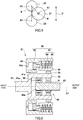
manual transmission 21, the continuouslyvariable transmission 22, and theelectric power generator 23 do not have to be lined up in a row. For example, as shown inFIG. 5 , the axes X1 to X3 may be set such that: the axis X1 of themanual transmission 21 is located between the axis X2 of the continuouslyvariable transmission 22 and the axis X3 of theelectric power generator 23 in the arrangement direction D; and a line connecting the axis X1 and the axis X2 may form an angle θ with respect to the arrangement direction D, i.e., the angle θ between a line connecting the axis X2 and the axis X3 and the line connecting the axis X1 and the axis X2 is larger than 0° and smaller than 90°. - In the present embodiment, the
input shaft 41 and theoutput shaft 42 of themanual transmission 21 are coaxially arranged. The axis X1 of the input andoutput shafts manual transmission 21 is arranged between the continuouslyvariable transmission 22 and theelectric power generator 23. According to this configuration, a power transmission path extending from themanual transmission 21 through the continuouslyvariable transmission 22 to theelectric power generator 23 is made compact. - The attaching
portion 31b is smaller in diameter than the housingmain body portion 31a. The continuouslyvariable transmission 22 and theelectric power generator 23 are accommodated in the housingmain body portion 31a, and themanual transmission 21 is supported by the attachingportion 31b by being fitted to an inner peripheral surface of the attachingportion 31b. To be specific, since the attachingportion 31b of thehousing 31 can be utilized as a support structure for themanual transmission 21, the support structure for themanual transmission 21 is simplified. Moreover, since an inner peripheral space of the attachingportion 31b is utilized as an accommodating space accommodating themanual transmission 21, theIDG unit 30 is made compact by effective utilization of the space. Furthermore, since themanual transmission 21 is provided at the inner peripheral surface of the attachingportion 31b of thehousing 31, the attachingportion 31b is relatively large in diameter, and attachment stability of thehousing 31 improves. -
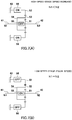
FIG. 6 is a sectional view showing themanual transmission 21 shown inFIG. 3 . As shown inFIG. 6 , themanual transmission 21 includes aplanetary gear mechanism 40, theinput shaft 41, theoutput shaft 42, and acasing 43. Theplanetary gear mechanism 40 includes asun gear 51, aring gear 52, aplanetary gear 53, acarrier 54, a one-way clutch 55, and abrake 56. Theinput shaft 41 is connected to thecarrier 54 holding theplanetary gear 53 of theplanetary gear mechanism 40. Theoutput shaft 42 is connected to thesun gear 51 of theplanetary gear mechanism 40. Thebrake 56 supported by thecasing 43 is connected to thering gear 52. - The
input shaft 41 includes: afirst shaft portion 41a projecting from thecasing 43 toward an input side; and asecond shaft portion 41b accommodated in thecasing 43. Thesecond shaft portion 41b is connected to thecarrier 54. Thesecond shaft portion 41b is tubular and includes an internal space that is open toward theoutput shaft 42. It should be noted that inFIG. 6 , thecarrier 54 is formed integrally with theinput shaft 41, but thecarrier 54 may be formed separately from theinput shaft 41 and may be fixed to theinput shaft 41. - The
output shaft 42 includes atip end portion 42a inserted into the internal space of the tubularsecond shaft portion 41b. Thetip end portion 42a of theoutput shaft 42 is supported by thesecond shaft portion 41b of theinput shaft 41 through a bearing (not shown) such that theoutput shaft 42 is rotatable. Thesun gear 51 is connected to a portion of theoutput shaft 42 which portion is located at an output side of thetip end portion 42a (i.e., located downstream of thetip end portion 42a). - The one-way clutch 55 is sandwiched between the
input shaft 41 and theoutput shaft 42. Specifically, the one-way clutch 55 is annular and is sandwiched between an inner peripheral surface of thesecond shaft portion 41b of theinput shaft 41 and an outer peripheral surface of thetip end portion 42a of theoutput shaft 42. The one-way clutch 55 transmits power only in one rotational direction and does not transmit the power in an opposite rotational direction. The one-way clutch 55 transmits rotational power from theinput shaft 41 to theoutput shaft 42 but does not transmit the rotational power from theoutput shaft 42 to theinput shaft 41. For example, the one-way clutch 55 is of a known sprag type. The one-way clutch 55 is arranged at a radially inner side of thering gear 52. - The
ring gear 52 includes internal teeth which mesh with theplanetary gear 53. Thebrake 56 is connected to an outer peripheral surface of thering gear 52 while being supported by thecasing 43. Thebrake 56 operates between an operating state in which thering gear 52 is fixed to thecasing 43 and a non-operating state in which thering gear 52 is rotatable relative to thecasing 43. Specifically, thebrake 56 includes afriction clutch 61 and apiston 62 configured to apply press-contact force to thefriction clutch 61. It should be noted that thebrake 56 may include a component other than the friction clutch as long as thebrake 56 can realize a state where thering gear 52 is unrotatable relative to thecasing 43 and a state where thering gear 52 is rotatable relative to thecasing 43. - The
friction clutch 61 is interposed between an inner peripheral surface of thecasing 43 and the outer peripheral surface of thering gear 52. Thefriction clutch 61 is, for example, a multiple disc clutch. Specifically, thefriction clutch 61 includes afriction plate 65 and amating plate 66. Thefriction plate 65 is connected to thering gear 52 so as to be unrotatable relative to thering gear 52 and movable relative to thering gear 52 in the direction along the axis X1. Themating plate 66 is connected to thecasing 43 so as to be unrotatable relative to thecasing 43 and movable relative to thecasing 43 in the direction along the axis X1. - The
piston 62 is opposed to thefriction clutch 61. Thepiston 62 is supported by thecasing 43 so as to be slidable. Thecasing 43 includes ahydraulic pressure passage 43a through which hydraulic pressure is applied to thepiston 62. Pressure oil is supplied to the hydraulic pressure passage 43b by a hydraulic pump (not shown) driven by the power of theaircraft engine 1. - Since the pressure oil supplied from the
hydraulic pressure passage 43a pushes thepiston 62, thepiston 62 presses thefriction clutch 61, and thefriction clutch 61 becomes an engaged state (the operating state of the brake 56). When the hydraulic pressure applied from thehydraulic circuit 43a to thepiston 62 decreases, and thepiston 62 retreats, thefriction clutch 61 becomes a disengaged state (the non-operating state of the brake 56). It should be noted that the actuator configured to press thefriction clutch 61 is not limited to a hydraulic actuator, such as thepiston 62, and may be a different actuator (for example, an electromagnetic actuator). - According to the above configuration, the
manual transmission 21 can be formed in a thin shape that is compact in the direction along the axis X1. Therefore, an occupied space located upstream of the continuouslyvariable transmission 22 in theIDG unit 30 is suppressed. Moreover, since themanual transmission 21 is of a thin type, the manual transmission 21b is stably supported by the attachingportion 31b while being accommodated in the inner peripheral space of the attachingportion 31b of theIDG unit 30. -
FIGS. 7A and 7B are schematic diagrams for explaining an operation principle of themanual transmission 21 shown inFIG. 6 . As shown inFIG. 7A , in themanual transmission 21, when thebrake 56 becomes the operating state, thering gear 52 is fixed to thecasing 43, and the rotational power of theinput shaft 41 is transmitted to theoutput shaft 42 through thecarrier 54, theplanetary gear 53, and thesun gear 51. Thus, speed increase is performed (N1 < N2). On the other hand, as shown inFIG. 6B , in themanual transmission 21, when thebrake 56 becomes the non-operating state, thering gear 52 is rotatable relative to thecasing 43, and the rotational power of theinput shaft 41 is transmitted to theoutput shaft 42 through the one-way clutch 55 at equal speed (N1 = N2). - To be specific, when the
brake 56 becomes the operating state, themanual transmission 21 becomes a high-speed stage (speed increase) that is the upper stage. When thebrake 56 becomes the non-operating state, themanual transmission 21 is set to a low-speed stage (equal speed) that is the lower stage. However, the present embodiment is not limited to this as long as the upper stage is larger in a speed increasing ratio (smaller in the reduction ratio) than the lower stage. For example, the combination of two gear stages (the high-speed stage and the low-speed stage) of themanual transmission 21 does not have to be the combination of the speed increasing stage and the equal speed stage and may be, for example, the combination of the speed increasing stage and a speed decreasing stage or the combination of the equal speed stage and the speed decreasing stage. - According to this configuration, when the
brake 56 changes from the operating state to the non-operating state, the rotational frequency of theoutput shaft 42 connected to the load (electric power generator 23) decreases as compared to the rotational frequency of theinput shaft 41. When the rotational frequency of theoutput shaft 42 becomes equal to the rotational frequency of theinput shaft 41, the one-way clutch 55 becomes an engaged state, and the rotational power of theinput shaft 41 is transmitted to theoutput shaft 42 at equal speed. To be specific, two-stage speed change (equal speed and speed increase) can be realized by switching the operating state of thebrake 56. Then, since the two-stage manual transmission 21 is included in the electricpower generating apparatus 13, the apparatus can be made compact. -
- 1
- aircraft engine
- 13
- electric power generating apparatus
- 20
- emergency cut-off device
- 21
- manual transmission
- 22
- continuously variable transmission
- 23
- electric power generator
- 27
- electric power generation controller
- 30
- IDG unit
- 31
- housing
- 31b
- attaching portion
- 40
- planetary gear mechanism
- 41
- input shaft
- 42
- output shaft
- 43
- casing
- 51
- sun gear
- 52
- ring gear
- 53
- planetary gear
- 54
- carrier
- 55
- one-way clutch
- 56
- brake
- 61
- friction clutch
- 62
- piston
Claims (8)
- An electric power generating apparatus for use in an aircraft,
the electric power generating apparatus comprising:an emergency cut-off device connected to a gear box to which rotational power of an aircraft engine is transmitted;a manual transmission configured to change speed of the rotational power transmitted from the emergency cut-off device, the manual transmission including a plurality of gear stages; andan electric power generator to which the rotational power which has been changed in speed by the manual transmission is transmitted. - The electric power generating apparatus according to claim 1, further comprising a housing accommodating the manual transmission and the electric power generator.
- The electric power generating apparatus according to claim 2, wherein:the housing includes an attaching portion at which an input opening is formed;the manual transmission is arranged in an accommodating space of the housing so as to be located close to the attaching portion; andan input shaft of the manual transmission is inserted into the input opening.
- The electric power generating apparatus according to claim 3, wherein the manual transmission is supported by an inner peripheral surface of the attaching portion of the housing.
- The electric power generating apparatus according to any one of claims 1 to 4, further comprising a continuously variable transmission interposed on a power transmission path between the manual transmission and the electric power generator.
- The electric power generating apparatus according to claim 5, wherein:the continuously variable transmission and the electric power generator are arranged such that an axis of the continuously variable transmission and an axis of the electric power generator are parallel to each other when viewed from at least one direction; andwhen viewed from a direction along the axes, the manual transmission is arranged so as to overlap the continuously variable transmission and the electric power generator.
- The electric power generating apparatus according to claim 6, wherein:the axis of the continuously variable transmission and the axis of the electric power generator are lined up in a predetermined arrangement direction; andan axis of the output shaft of the manual transmission is located between the axis of the continuously variable transmission and the axis of the electric power generator in the arrangement direction.
- The electric power generating apparatus according to claim 7, wherein the axis of the output shaft of the manual transmission is arranged between the continuously variable transmission and the electric power generator.
Applications Claiming Priority (1)
| Application Number | Priority Date | Filing Date | Title |
|---|---|---|---|
| PCT/JP2018/042644 WO2020105084A1 (en) | 2018-11-19 | 2018-11-19 | Power generation apparatus for aircraft |
Publications (3)
| Publication Number | Publication Date |
|---|---|
| EP3885561A1 true EP3885561A1 (en) | 2021-09-29 |
| EP3885561A4 EP3885561A4 (en) | 2022-06-22 |
| EP3885561B1 EP3885561B1 (en) | 2026-05-27 |
Family
ID=70773143
Family Applications (1)
| Application Number | Title | Priority Date | Filing Date |
|---|---|---|---|
| EP18940548.3A Active EP3885561B1 (en) | 2018-11-19 | 2018-11-19 | Electric power generating apparatus for use in aircraft |
Country Status (4)
| Country | Link |
|---|---|
| US (1) | US11859559B2 (en) |
| EP (1) | EP3885561B1 (en) |
| JP (1) | JP7108709B2 (en) |
| WO (1) | WO2020105084A1 (en) |
Family Cites Families (13)
| Publication number | Priority date | Publication date | Assignee | Title |
|---|---|---|---|---|
| US4315442A (en) * | 1980-02-15 | 1982-02-16 | Sundstrand Corporation | Aircraft generator starter-drive |
| US4734590A (en) * | 1986-12-30 | 1988-03-29 | Sundstrand Corporation | Integrated drive generator with common center line |
| JP3440287B2 (en) | 1999-12-01 | 2003-08-25 | 川崎重工業株式会社 | Constant speed driving method and constant speed driving apparatus for aircraft generator |
| JP3593575B2 (en) | 2001-02-08 | 2004-11-24 | 川崎重工業株式会社 | Single-shaft gas turbine system |
| JP4035423B2 (en) * | 2002-10-22 | 2008-01-23 | 本田技研工業株式会社 | transmission |
| TWI330218B (en) * | 2004-10-29 | 2010-09-11 | Tai Her Yang | Split serial-parallel hybrid dual-power drive system |
| JP4700113B2 (en) * | 2009-02-06 | 2011-06-15 | 川崎重工業株式会社 | Aircraft generator |
| US8561503B2 (en) | 2011-07-28 | 2013-10-22 | Hamilton Sundstrand Corporation | Motor-generator and prime mover gearing assembly |
| US20130076035A1 (en) * | 2011-09-27 | 2013-03-28 | Andreas C. Koenig | Motor-generator turbomachine starter |
| US9121476B2 (en) * | 2013-04-12 | 2015-09-01 | Hamilton Sundstrand Corporation | Control of shifting transmission for constant and variable frequency systems |
| US9574618B2 (en) * | 2014-11-20 | 2017-02-21 | Hamilton Sundstrand Corporation | Thermal disconnect assembly with flight control permanent magnet generator for integrated drive generator |
| JP6343243B2 (en) * | 2015-03-09 | 2018-06-13 | 川崎重工業株式会社 | Aircraft power generator |
| JP6368674B2 (en) * | 2015-03-24 | 2018-08-01 | ジヤトコ株式会社 | Torque cam device for automatic transmission |
-
2018
- 2018-11-19 US US17/294,017 patent/US11859559B2/en active Active
- 2018-11-19 WO PCT/JP2018/042644 patent/WO2020105084A1/en not_active Ceased
- 2018-11-19 EP EP18940548.3A patent/EP3885561B1/en active Active
- 2018-11-19 JP JP2020557036A patent/JP7108709B2/en active Active
Also Published As
| Publication number | Publication date |
|---|---|
| EP3885561B1 (en) | 2026-05-27 |
| JP7108709B2 (en) | 2022-07-28 |
| WO2020105084A1 (en) | 2020-05-28 |
| US20220003171A1 (en) | 2022-01-06 |
| EP3885561A4 (en) | 2022-06-22 |
| JPWO2020105084A1 (en) | 2021-10-14 |
| US11859559B2 (en) | 2024-01-02 |
Similar Documents
| Publication | Publication Date | Title |
|---|---|---|
| US10815900B2 (en) | Geared gas turbine engine | |
| US10954813B2 (en) | Planetary gearbox system and method for operating a planetary gearbox system | |
| CN103987941B (en) | Fan drive gear system for gas turbine engine and gas turbine engine | |
| EP3321494B1 (en) | Gearbox for gas turbine engine | |
| US10094295B2 (en) | Gas turbine engine with transmission | |
| EP2992198B1 (en) | Two shaft turbo machine | |
| EP2320067B1 (en) | Aircraft starter generator | |
| EP3401531B1 (en) | Air turbine starter comprising a planetary gear system | |
| EP2644867B1 (en) | Aircraft accessory drive multiple speed transmission | |
| EP3257753B1 (en) | Reduction gearbox for aircraft engine | |
| EP2789875B1 (en) | Transmission for constant and variable frequency systems and method for controlling a transmission | |
| US10385946B2 (en) | Powertrain system and method for operating a powertrain | |
| EP3572637A1 (en) | Gas turbine engine coupling arrangement | |
| EP3885564B1 (en) | Electric power generating apparatus for use in aircraft | |
| US11859559B2 (en) | Electric power generating apparatus for use in aircraft | |
| JP2002332871A (en) | Gas turbine power generation equipment | |
| EP3885563B1 (en) | Electric power generation controller for use in aircraft and electric power generating apparatus including same | |
| EP3885562B1 (en) | Electric power generation controller for use in aircraft | |
| SE525590C2 (en) | power quality |
Legal Events
| Date | Code | Title | Description |
|---|---|---|---|
| STAA | Information on the status of an ep patent application or granted ep patent |
Free format text: STATUS: THE INTERNATIONAL PUBLICATION HAS BEEN MADE |
|
| PUAI | Public reference made under article 153(3) epc to a published international application that has entered the european phase |
Free format text: ORIGINAL CODE: 0009012 |
|
| STAA | Information on the status of an ep patent application or granted ep patent |
Free format text: STATUS: REQUEST FOR EXAMINATION WAS MADE |
|
| 17P | Request for examination filed |
Effective date: 20210520 |
|
| AK | Designated contracting states |
Kind code of ref document: A1 Designated state(s): AL AT BE BG CH CY CZ DE DK EE ES FI FR GB GR HR HU IE IS IT LI LT LU LV MC MK MT NL NO PL PT RO RS SE SI SK SM TR |
|
| DAV | Request for validation of the european patent (deleted) | ||
| DAX | Request for extension of the european patent (deleted) | ||
| A4 | Supplementary search report drawn up and despatched |
Effective date: 20220525 |
|
| RIC1 | Information provided on ipc code assigned before grant |
Ipc: F16H 15/38 20060101ALI20220519BHEP Ipc: F16H 3/54 20060101ALI20220519BHEP Ipc: F02C 7/32 20060101ALI20220519BHEP Ipc: F02C 7/36 20060101AFI20220519BHEP |
|
| STAA | Information on the status of an ep patent application or granted ep patent |
Free format text: STATUS: EXAMINATION IS IN PROGRESS |
|
| 17Q | First examination report despatched |
Effective date: 20240528 |
|
| GRAP | Despatch of communication of intention to grant a patent |
Free format text: ORIGINAL CODE: EPIDOSNIGR1 |
|
| STAA | Information on the status of an ep patent application or granted ep patent |
Free format text: STATUS: GRANT OF PATENT IS INTENDED |
|
| INTG | Intention to grant announced |
Effective date: 20260119 |
|
| GRAS | Grant fee paid |
Free format text: ORIGINAL CODE: EPIDOSNIGR3 |
|
| GRAA | (expected) grant |
Free format text: ORIGINAL CODE: 0009210 |
|
| STAA | Information on the status of an ep patent application or granted ep patent |
Free format text: STATUS: THE PATENT HAS BEEN GRANTED |
|
| AK | Designated contracting states |
Kind code of ref document: B1 Designated state(s): AL AT BE BG CH CY CZ DE DK EE ES FI FR GB GR HR HU IE IS IT LI LT LU LV MC MK MT NL NO PL PT RO RS SE SI SK SM TR |
|
| REG | Reference to a national code |
Ref country code: CH Ref legal event code: F10 Free format text: ST27 STATUS EVENT CODE: U-0-0-F10-F00 (AS PROVIDED BY THE NATIONAL OFFICE) Effective date: 20260527 Ref country code: GB Ref legal event code: FG4D |
|
| REG | Reference to a national code |
Ref country code: DE Ref legal event code: R096 Ref document number: 602018091585 Country of ref document: DE |