EP3885558A1 - Exhaust baffle component for an air turbine assembly - Google Patents
Exhaust baffle component for an air turbine assembly Download PDFInfo
- Publication number
- EP3885558A1 EP3885558A1 EP21164331.7A EP21164331A EP3885558A1 EP 3885558 A1 EP3885558 A1 EP 3885558A1 EP 21164331 A EP21164331 A EP 21164331A EP 3885558 A1 EP3885558 A1 EP 3885558A1
- Authority
- EP
- European Patent Office
- Prior art keywords
- baffle
- airflow
- airflow channels
- level
- component
- Prior art date
- Legal status (The legal status is an assumption and is not a legal conclusion. Google has not performed a legal analysis and makes no representation as to the accuracy of the status listed.)
- Withdrawn
Links
Images



Classifications
-
- F—MECHANICAL ENGINEERING; LIGHTING; HEATING; WEAPONS; BLASTING
- F02—COMBUSTION ENGINES; HOT-GAS OR COMBUSTION-PRODUCT ENGINE PLANTS
- F02C—GAS-TURBINE PLANTS; AIR INTAKES FOR JET-PROPULSION PLANTS; CONTROLLING FUEL SUPPLY IN AIR-BREATHING JET-PROPULSION PLANTS
- F02C7/00—Features, components parts, details or accessories, not provided for in, or of interest apart form groups F02C1/00 - F02C6/00; Air intakes for jet-propulsion plants
- F02C7/26—Starting; Ignition
- F02C7/268—Starting drives for the rotor, acting directly on the rotor of the gas turbine to be started
- F02C7/275—Mechanical drives
- F02C7/277—Mechanical drives the starter being a separate turbine
-
- F—MECHANICAL ENGINEERING; LIGHTING; HEATING; WEAPONS; BLASTING
- F01—MACHINES OR ENGINES IN GENERAL; ENGINE PLANTS IN GENERAL; STEAM ENGINES
- F01D—NON-POSITIVE DISPLACEMENT MACHINES OR ENGINES, e.g. STEAM TURBINES
- F01D9/00—Stators
- F01D9/02—Nozzles; Nozzle boxes; Stator blades; Guide conduits, e.g. individual nozzles
-
- F—MECHANICAL ENGINEERING; LIGHTING; HEATING; WEAPONS; BLASTING
- F01—MACHINES OR ENGINES IN GENERAL; ENGINE PLANTS IN GENERAL; STEAM ENGINES
- F01D—NON-POSITIVE DISPLACEMENT MACHINES OR ENGINES, e.g. STEAM TURBINES
- F01D9/00—Stators
- F01D9/02—Nozzles; Nozzle boxes; Stator blades; Guide conduits, e.g. individual nozzles
- F01D9/04—Nozzles; Nozzle boxes; Stator blades; Guide conduits, e.g. individual nozzles forming ring or sector
- F01D9/045—Nozzles; Nozzle boxes; Stator blades; Guide conduits, e.g. individual nozzles forming ring or sector for radial flow machines or engines
-
- F—MECHANICAL ENGINEERING; LIGHTING; HEATING; WEAPONS; BLASTING
- F02—COMBUSTION ENGINES; HOT-GAS OR COMBUSTION-PRODUCT ENGINE PLANTS
- F02C—GAS-TURBINE PLANTS; AIR INTAKES FOR JET-PROPULSION PLANTS; CONTROLLING FUEL SUPPLY IN AIR-BREATHING JET-PROPULSION PLANTS
- F02C7/00—Features, components parts, details or accessories, not provided for in, or of interest apart form groups F02C1/00 - F02C6/00; Air intakes for jet-propulsion plants
- F02C7/26—Starting; Ignition
-
- F—MECHANICAL ENGINEERING; LIGHTING; HEATING; WEAPONS; BLASTING
- F05—INDEXING SCHEMES RELATING TO ENGINES OR PUMPS IN VARIOUS SUBCLASSES OF CLASSES F01-F04
- F05D—INDEXING SCHEME FOR ASPECTS RELATING TO NON-POSITIVE-DISPLACEMENT MACHINES OR ENGINES, GAS-TURBINES OR JET-PROPULSION PLANTS
- F05D2220/00—Application
- F05D2220/50—Application for auxiliary power units (APU's)
-
- F—MECHANICAL ENGINEERING; LIGHTING; HEATING; WEAPONS; BLASTING
- F05—INDEXING SCHEMES RELATING TO ENGINES OR PUMPS IN VARIOUS SUBCLASSES OF CLASSES F01-F04
- F05D—INDEXING SCHEME FOR ASPECTS RELATING TO NON-POSITIVE-DISPLACEMENT MACHINES OR ENGINES, GAS-TURBINES OR JET-PROPULSION PLANTS
- F05D2240/00—Components
- F05D2240/10—Stators
- F05D2240/12—Fluid guiding means, e.g. vanes
- F05D2240/126—Baffles or ribs
-
- F—MECHANICAL ENGINEERING; LIGHTING; HEATING; WEAPONS; BLASTING
- F05—INDEXING SCHEMES RELATING TO ENGINES OR PUMPS IN VARIOUS SUBCLASSES OF CLASSES F01-F04
- F05D—INDEXING SCHEME FOR ASPECTS RELATING TO NON-POSITIVE-DISPLACEMENT MACHINES OR ENGINES, GAS-TURBINES OR JET-PROPULSION PLANTS
- F05D2240/00—Components
- F05D2240/10—Stators
- F05D2240/12—Fluid guiding means, e.g. vanes
- F05D2240/129—Cascades, i.e. assemblies of similar profiles acting in parallel
-
- F—MECHANICAL ENGINEERING; LIGHTING; HEATING; WEAPONS; BLASTING
- F05—INDEXING SCHEMES RELATING TO ENGINES OR PUMPS IN VARIOUS SUBCLASSES OF CLASSES F01-F04
- F05D—INDEXING SCHEME FOR ASPECTS RELATING TO NON-POSITIVE-DISPLACEMENT MACHINES OR ENGINES, GAS-TURBINES OR JET-PROPULSION PLANTS
- F05D2260/00—Function
- F05D2260/85—Starting
Definitions
- Exemplary embodiments pertain to the art of starter assemblies for engines, such as gas turbine engines and, more particularly, to exhaust baffle components to assist in directing airflow within a starter assembly of the engine.
- ATS air turbine starter
- the ATS is typically mounted on an accessory gearbox which, in turn, is mounted on the engine or airframe. Consequently, the ATS is installed in the aircraft at all times even though active operation may occur only for a minute or so at the beginning of each flight cycle, along with occasional operation during engine maintenance activities.
- the ATS generally includes a turbine section coupled to an output section within a housing.
- the turbine section is coupled to a high pressure fluid source, such as compressed air, to drive the output section through a gear system.
- a high pressure fluid source such as compressed air
- the ATS generally includes an exhaust baffle downstream of the turbine section.
- exhaust baffles assemblies for a turbine starter are provided.
- the baffles are configured to assist in directing airflow within a starter assembly of an engine.
- the baffle includes a first baffle level and a second baffle level stacked with the first baffle level.
- the baffle levels are arranged with a starter assembly such that airflow entering the baffle levels is directed by the first baffle level and the second baffle level to exit the starter assembly.
- the first baffle level may include a plurality of first airflow channels and the second baffle level may include a plurality of second airflow channels.
- each of the plurality of first airflow channels share a wall with one of the plurality of second airflow channels.
- the first airflow channel of the plurality of first airflow channels is defined by a pair of fins spaced from one another and extending between the shared wall and a lower wall.
- the first baffle level may include an upper outer edge and the shared wall extends from the upper outer edge.
- the first baffle level and the second baffle level may define a first attachment feature at a first end and a second attachment feature at a second end.
- the attachment features are configured to facilitate a connection between adjacent baffle sections.
- the connected adjacent baffle sections define a substantially circular shape defining a first central axis.
- the baffle levels may be arranged with one another such that a first airflow traveling through the first baffle level is in a direction substantially parallel with a second airflow traveling through the second baffle level.
- the shared wall may be oriented at an angle substantially between zero and ninety degrees relative to the first central axis defined by the substantially circular shape.
- the baffle levels may be arranged with one another such that airflow from the starter assembly is exhausted via two airflow channels.
- the first baffle level and the second baffle level may be formed via additive manufacturing.
- the first baffle level may include a plurality of first airflow channels and the second baffle level may include a plurality of second airflow channels.
- each first airflow channel of the plurality of first airflow channels defines an airflow central plane and each second airflow channel of the plurality of second airflow channels is oriented substantially parallel to the airflow central plane.
- starter assemblies for turbines are provided.
- the starter assembly includes a baffle component.
- the baffle component includes a plurality of first airflow channels.
- the first airflow channels are defined by a pair of fins spaced from one another, a lower wall, and a shared wall.
- the baffle component includes a plurality of second airflow channels.
- the second airflow channels are defined by one of the pairs of fins and the shared wall. Further, each of the pairs of fins extend through the shared wall such that each of the pairs of fins partially define one of the plurality of first airflow channels and one of the plurality of second airflow channels.
- the plurality of second airflow channels may be arranged in a stack with the plurality of first airflow channels such that the shared wall partially defines each airflow channel of the plurality of first airflow channels and partially defines each airflow channel of the plurality of second airflow channels.
- the baffle component may be arranged to define a central axis and the baffle component further has one or more posts, each post of the one or more posts extending through the baffle levels and being disposed equidistant from the central axis.
- the baffle component may include a plurality of components.
- Each of the plurality of components includes a first end for securing to a first adjacent component and a second end for securing to a second adjacent component.
- the plurality of components may be arranged with one another to define a substantially circular shape about a baffle central axis.
- the plurality of components may be arranged such that the baffle central axis is oriented substantially perpendicular to an axis of an adjacent engine.
- the baffle component may include more than one baffle section.
- Each of the more than one baffle sections are arranged with one another to define a central axis and the shared wall is oriented at an angle substantially between zero and ninety degrees relative to the central axis.
- each airflow channel of the plurality of first airflow channels may influence a first airflow therethrough in a direction substantially parallel to an airflow direction of a second airflow traveling through each airflow channel of the plurality of second airflow channels.
- the baffle component may be formed via additive manufacturing.
- each first airflow channel of the plurality of first airflow channels may define an airflow central plane and each second airflow channel of the plurality of second airflow channels is oriented substantially parallel to the airflow central plane.
- FIG. 1A schematically illustrates an example of a gas turbine engine 20.
- the gas turbine engine 20 includes a fan section 22, a compressor section 24, a combustor section 26, and a turbine section 28.
- Each of the fan section 22, the compressor section 24, the combustor section 26, and the turbine section 28 is arranged with one another to define an engine central longitudinal axis A
- a gear box 100 may be mounted to a housing of the gas turbine engine 20 at a location adjacent one of the compressor section 24, the combustor section 26, or the turbine section 28 to facilitate mechanical communication between the engine and the gearbox.
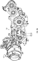
- FIG. 1B is a perspective view showing the gear box 100 connected to a starter assembly 102 of FIG. 1A .
- the starter assembly 102 may be an air turbine starter.
- Components of the gear box 100 may be arranged with components of the gas turbine engine 20 to transfer mechanical energy between the gas turbine engine 20 and the starter assembly 102 in either direction. While the starter assembly 102 is shown in communication with the gas turbine engine 20 in FIG. 1A , those in the art will appreciate that the starter assembly 102 may operate with other types of engines without departing from a scope of the present disclosure.
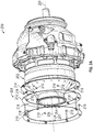
- FIGS. 2A and 2B show an example of a starter assembly of a gas turbine engine, referred to generally as a starter assembly 200 herein.
- the starter assembly 200 may be an air turbine starter.
- a housing 202 defines an opening 204.
- the opening 204 defines a central axis 206. Air enters the housing 202 via the opening 204 in a direction substantially parallel to the central axis 206 as represented by arrow 207 in FIG. 2A .
- Air exiting the housing 202 is represented by arrows 209 in FIG. 2B and exits through spacing between baffle louvers described below. Arrows 209 are also generally shown in FIG. 2a for context.
- the starter assembly 200 includes multiple additional components.
- the starter assembly can include an exhaust baffle assembly 208.
- the exhaust baffle assembly 208 includes separately formed components such as a first baffle louver 210, a second baffle louver 212, a third baffle louver 214, and a plurality of spacers 218. Each of these separately formed components must then be assembled with one another, a burdensome task. While the exhaust baffle assembly 208 is shown with three baffle louvers in FIGS. 2A and 2B , those skilled in the art will appreciate that the exhaust baffle assembly 208 may include more than three baffle louvers.
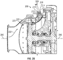
- FIG. 2B shows further detail related to an assembled version of the separately formed components discussed above.
- the assembly process alternately stacks the baffle louvers and the spacers 218.
- the baffle louvers When assembled, the baffle louvers are oriented with one another in an overlap-fashion relative to airflow originating near the central axis 206 and traveling toward the baffle assembly 208 as represented by arrows 222 in FIG. 2B .
- air may travel from the opening 204 to the baffle assembly 208 via a channel 223.
- the overlap-fashion of the baffle louvers interferes with continuous exhaust airflow through the baffle assembly 208 as all or most of the exhaust airflow contacts one of the first baffle louver 210, the second baffle louver 212, or the third baffle louver 214.
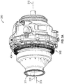
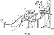
- FIGS. 3A and 3B illustrate an example of an engine starter assembly according to the present disclosure, referred to generally as an engine starter assembly 300 herein, and a portion of a baffle component for the engine starter assembly 300, referred to generally as a baffle component 302 herein.
- the engine starter assembly 300 and the baffle component 302 may be utilized in aircraft starters or other similar starters.
- the starter assembly 300 may be coupled to a gear box in mechanical communication with an engine.
- the engine starter assembly 300 may be mounted adjacent to a portion of the engine, such as the gear box 100 described above in relation to the gas turbine engine 20.
- the baffle component 302 may include a plurality of sections 404 connected to one another or formed as a single component. Each section 404 of the plurality of sections 404 may be spaced equidistant from a starter assembly central axis 310. In one example, each section 404 of the plurality of sections 404 may be arranged with one another to define a substantially circular shape about the starter assembly central axis 310. In another example, the starter assembly central axis 310 may be defined by an opening 311.
- the baffle component 302 may be arranged with components of the engine starter assembly 300 to assist in managing airflow direction therein. Air may travel from the opening 311 to the baffle component 302 via an air channel 312 as represented with arrows 313 in FIG. 3B . Air may enter the starter assembly 300 at a location adjacent the starter assembly central axis 310 and travel in a direction parallel therewith as represented by arrow 314. Air may exit the starter assembly 300 via the baffle component 302 as represented by arrow 315 of FIG. 3B .
- the baffle component 302 may include a plurality of baffle sections 404 secured to one another or formed as a single unit. Each of the baffle sections 404 may be arranged with one another to define a substantially circular shape about the central axis 310. While FIG. 4A shows a plurality of baffle sections 404, those skilled in the art will appreciate that there may be more or fewer baffle sections 404 of varying shapes based on available packaging space and desired performance metrics without departing from a scope of the present disclosure.
- the baffle component 302 may include one or more posts 406 to secure the baffle component 302 to a supporting structure, such as a starter assembly. While shown as having a cylindrical shape in FIGS. 4A and 4B , those skilled in the art will appreciate that each of the one or more posts 406 may have a different shape without departing from a scope of the present disclosure.
- the baffle component 302 may define one or more post openings 407 to receive one of the one or more posts 406 or the one or more posts 406 may be formed with the rest of the baffle component 302 as a single unit.
- the baffle component 302 may be formed via additive manufacturing, for example layer-by-layer additive manufacturing. Layer-by-layer additive manufacturing involves forming successive layers on top of one another to form an object.
- the baffle component 302 may be formed via a stamping process.
- FIG. 4B is a perspective view of one of the baffle sections 404 illustrating additional detail.
- Each of the baffle sections 404 may have multiple baffle levels including a first baffle level 408 stacked with a second baffle level 410.
- the first baffle level 408 may include a plurality of first airflow channels 414 and the second baffle level 410 may include a plurality of second airflow channels 416.
- Each airflow channel of the plurality of first airflow channels 414 and the plurality of second airflow channels 416 may be defined by walls.
- each airflow channel of the plurality of first airflow channels 414 is partially defined by a shared wall 420.
- the shared wall 420 may define a portion of each of the plurality of first airflow channels 414 and each of the plurality of second airflow channels 416.
- the shared wall 420 may extend from an upper outer edge 424 of the baffle component 302.
- Fins 428 may be spaced from one another along the baffle component 302 to further define the airflow channels.
- a lower wall 430 may extend about the central axis 310 and further define each airflow channel 414 of the plurality of first airflow channels 414.
- a portion of the shared wall 420, a portion of the lower wall 430, and respective adjacent fins 428 may be arranged with one another to define one of the plurality of first airflow channels 414.
- each of the fins 428 may extend from the lower wall 430 to the shared wall 420.
- Each of the fins 428 may define a portion of both of one of the plurality of first airflow channels 414 and one of the plurality of second airflow channels 416.
- fins 428 may be curved in the direction of continuous exhaust airflow through baffle assembly 208 to avoid a sharp airflow turn.
- the first baffle level 408 and the second baffle level 410 may separately or together define a first attachment feature at a first end 460 and a second attachment feature at a second end 462. Each of the attachment features may be configured to facilitate connection between adjacent baffle levels and adjacent baffle sections 404 as shown in FIG. 4A .
- FIG. 4C illustrates a side view, in cross-section, of a portion of the engine starter assembly 300 including the baffle component 302 of FIG. 4A , showing an example of fluid flow within the engine starter assembly 300.
- Airflow traveling from the opening 311 to the baffle component 302 via the air channel 312 is represented by arrow 313.
- Air exiting the engine starter assembly 300 via one of the plurality of first airflow channels 414 and/or one of the plurality of second airflow channels 416 is represented by arrows 350.
- the airflow represented by each arrow 350 of arrows 350 may travel in a direction substantially parallel to one another along a first channel axis 352 and a second channel axis 354, respectively.
- a shared wall 320 may be oriented at an angle 358 having a value substantially between zero and ninety degrees.
- the angle 358 may be further defined by the first channel axis 352 and a face axis 361 defined by a face 363.
Landscapes
- Engineering & Computer Science (AREA)
- Chemical & Material Sciences (AREA)
- Combustion & Propulsion (AREA)
- Mechanical Engineering (AREA)
- General Engineering & Computer Science (AREA)
- Structures Of Non-Positive Displacement Pumps (AREA)
- Exhaust Gas After Treatment (AREA)
Abstract
Description
- Exemplary embodiments pertain to the art of starter assemblies for engines, such as gas turbine engines and, more particularly, to exhaust baffle components to assist in directing airflow within a starter assembly of the engine.
- Many relatively large gas turbine engines, including turbofan engines, may use an air turbine starter (ATS) to initiate gas turbine engine rotation. The ATS is typically mounted on an accessory gearbox which, in turn, is mounted on the engine or airframe. Consequently, the ATS is installed in the aircraft at all times even though active operation may occur only for a minute or so at the beginning of each flight cycle, along with occasional operation during engine maintenance activities.
- The ATS generally includes a turbine section coupled to an output section within a housing. The turbine section is coupled to a high pressure fluid source, such as compressed air, to drive the output section through a gear system. Thus, when the high pressure fluid source impinges upon the turbine section, the output section powers the gas turbine engine. The ATS generally includes an exhaust baffle downstream of the turbine section.
- Current exhaust baffle assemblies for engine starters mount each of several individual baffles in parallel with a mounting face of an engine. Such assemblies include many components such as spacers between the individual baffles and are labor intensive to assemble. Further, due to the many components and assembly challenges, the baffle component of the starter assembly may experience cracking during use.
- According to some embodiments, exhaust baffles assemblies for a turbine starter are provided. The baffles are configured to assist in directing airflow within a starter assembly of an engine. The baffle includes a first baffle level and a second baffle level stacked with the first baffle level. The baffle levels are arranged with a starter assembly such that airflow entering the baffle levels is directed by the first baffle level and the second baffle level to exit the starter assembly.
- In addition to one or more of the features described above, or as an alternative, in further embodiments of the baffle, the first baffle level may include a plurality of first airflow channels and the second baffle level may include a plurality of second airflow channels. In addition, each of the plurality of first airflow channels share a wall with one of the plurality of second airflow channels.
- In addition to one or more of the features described above, or as an alternative, in further embodiments of the baffle, the first airflow channel of the plurality of first airflow channels is defined by a pair of fins spaced from one another and extending between the shared wall and a lower wall.
- In addition to one or more of the features described above, or as an alternative, in further embodiments of the baffle, the first baffle level may include an upper outer edge and the shared wall extends from the upper outer edge.
- In addition to one or more of the features described above, or as an alternative, in further embodiments of the baffle, the first baffle level and the second baffle level may define a first attachment feature at a first end and a second attachment feature at a second end. The attachment features are configured to facilitate a connection between adjacent baffle sections. The connected adjacent baffle sections define a substantially circular shape defining a first central axis.
- In addition to one or more of the features described above, or as an alternative, in further embodiments of the baffle, the baffle levels may be arranged with one another such that a first airflow traveling through the first baffle level is in a direction substantially parallel with a second airflow traveling through the second baffle level.
- In addition to one or more of the features described above, or as an alternative, in further embodiments of the baffle, the shared wall may be oriented at an angle substantially between zero and ninety degrees relative to the first central axis defined by the substantially circular shape.
- In addition to one or more of the features described above, or as an alternative, in further embodiments of the baffle, the baffle levels may be arranged with one another such that airflow from the starter assembly is exhausted via two airflow channels.
- In addition to one or more of the features described above, or as an alternative, in further embodiments of the baffle, the first baffle level and the second baffle level may be formed via additive manufacturing.
- In addition to one or more of the features described above, or as an alternative, in further embodiments of the baffle, the first baffle level may include a plurality of first airflow channels and the second baffle level may include a plurality of second airflow channels. In addition, each first airflow channel of the plurality of first airflow channels defines an airflow central plane and each second airflow channel of the plurality of second airflow channels is oriented substantially parallel to the airflow central plane.
- According to some embodiments, starter assemblies for turbines are provided. The starter assembly includes a baffle component. The baffle component includes a plurality of first airflow channels. The first airflow channels are defined by a pair of fins spaced from one another, a lower wall, and a shared wall. In addition, the baffle component includes a plurality of second airflow channels. The second airflow channels are defined by one of the pairs of fins and the shared wall. Further, each of the pairs of fins extend through the shared wall such that each of the pairs of fins partially define one of the plurality of first airflow channels and one of the plurality of second airflow channels.
- In addition to one or more of the features described above, or as an alternative, in further embodiments of the starter assembly, the plurality of second airflow channels may be arranged in a stack with the plurality of first airflow channels such that the shared wall partially defines each airflow channel of the plurality of first airflow channels and partially defines each airflow channel of the plurality of second airflow channels.
- In addition to one or more of the features described above, or as an alternative, in further embodiments of the starter assembly, the baffle component may be arranged to define a central axis and the baffle component further has one or more posts, each post of the one or more posts extending through the baffle levels and being disposed equidistant from the central axis.
- In addition to one or more of the features described above, or as an alternative, in further embodiments of the starter assembly, the baffle component may include a plurality of components. Each of the plurality of components includes a first end for securing to a first adjacent component and a second end for securing to a second adjacent component.
- In addition to one or more of the features described above, or as an alternative, in further embodiments of the starter assembly, the plurality of components may be arranged with one another to define a substantially circular shape about a baffle central axis.
- In addition to one or more of the features described above, or as an alternative, in further embodiments of the starter assembly, the plurality of components may be arranged such that the baffle central axis is oriented substantially perpendicular to an axis of an adjacent engine.
- In addition to one or more of the features described above, or as an alternative, in further embodiments of the starter assembly, the baffle component may include more than one baffle section. Each of the more than one baffle sections are arranged with one another to define a central axis and the shared wall is oriented at an angle substantially between zero and ninety degrees relative to the central axis.
- In addition to one or more of the features described above, or as an alternative, in further embodiments of the starter assembly, each airflow channel of the plurality of first airflow channels may influence a first airflow therethrough in a direction substantially parallel to an airflow direction of a second airflow traveling through each airflow channel of the plurality of second airflow channels.
- In addition to one or more of the features described above, or as an alternative, in further embodiments of the starter assembly, the baffle component may be formed via additive manufacturing.
- In addition to one or more of the features described above, or as an alternative, in further embodiments of the starter assembly, each first airflow channel of the plurality of first airflow channels may define an airflow central plane and each second airflow channel of the plurality of second airflow channels is oriented substantially parallel to the airflow central plane.
- The following descriptions should not be considered limiting in any way. With reference to the accompanying drawings, like elements are numbered alike:
-
FIG. 1A is a side view, in partial cross-section, of an example of a gas turbine engine including a gear box and a starter assembly; -
FIG. 1B is a perspective view of a starter assembly connected to a gear box; -
FIG. 2A is a perspective, partially exploded view of an example of a portion of a starter assembly of an engine; -
FIG 2B is a side view, in cross-section, of a portion of the starter assembly ofFIG. 2A ; -
FIG. 3A is a perspective view of an example of a portion of a starter assembly of an engine; -
FIG. 3B is a side view, in cross-section, of a portion of the starter assembly ofFIG. 3A ; -
FIG. 4A is a perspective view of an exhaust baffle component of the starter assembly ofFIG. 3A ; -
FIG. 4B is a perspective view of a portion of the exhaust baffle component ofFIG. 4A ; and -
FIG. 4C is a side view, in cross-section, of a portion of the starter assembly ofFIG. 3A illustrating an example of airflow influenced by the exhaust baffle component ofFIG. 4A . - A detailed description of one or more embodiments of the disclosed apparatus and method are presented herein by way of exemplification and not limitation with reference to the Figures.
-
FIG. 1A schematically illustrates an example of agas turbine engine 20. Thegas turbine engine 20 includes afan section 22, acompressor section 24, acombustor section 26, and aturbine section 28. Each of thefan section 22, thecompressor section 24, thecombustor section 26, and theturbine section 28 is arranged with one another to define an engine central longitudinal axis A - In some cases, a
gear box 100 may be mounted to a housing of thegas turbine engine 20 at a location adjacent one of thecompressor section 24, thecombustor section 26, or theturbine section 28 to facilitate mechanical communication between the engine and the gearbox. -
FIG. 1B is a perspective view showing thegear box 100 connected to astarter assembly 102 ofFIG. 1A . In one example, thestarter assembly 102 may be an air turbine starter. Components of thegear box 100 may be arranged with components of thegas turbine engine 20 to transfer mechanical energy between thegas turbine engine 20 and thestarter assembly 102 in either direction. While thestarter assembly 102 is shown in communication with thegas turbine engine 20 inFIG. 1A , those in the art will appreciate that thestarter assembly 102 may operate with other types of engines without departing from a scope of the present disclosure. -
FIGS. 2A and2B show an example of a starter assembly of a gas turbine engine, referred to generally as astarter assembly 200 herein. In one example, thestarter assembly 200 may be an air turbine starter. Ahousing 202 defines anopening 204. Theopening 204 defines acentral axis 206. Air enters thehousing 202 via theopening 204 in a direction substantially parallel to thecentral axis 206 as represented byarrow 207 inFIG. 2A . Air exiting thehousing 202 is represented byarrows 209 inFIG. 2B and exits through spacing between baffle louvers described below.Arrows 209 are also generally shown inFIG. 2a for context. Thestarter assembly 200 includes multiple additional components. For example, the starter assembly can include anexhaust baffle assembly 208. Theexhaust baffle assembly 208 includes separately formed components such as afirst baffle louver 210, asecond baffle louver 212, athird baffle louver 214, and a plurality ofspacers 218. Each of these separately formed components must then be assembled with one another, a burdensome task. While theexhaust baffle assembly 208 is shown with three baffle louvers inFIGS. 2A and2B , those skilled in the art will appreciate that theexhaust baffle assembly 208 may include more than three baffle louvers. -
FIG. 2B shows further detail related to an assembled version of the separately formed components discussed above. The assembly process alternately stacks the baffle louvers and thespacers 218. When assembled, the baffle louvers are oriented with one another in an overlap-fashion relative to airflow originating near thecentral axis 206 and traveling toward thebaffle assembly 208 as represented byarrows 222 inFIG. 2B . For example, air may travel from theopening 204 to thebaffle assembly 208 via achannel 223. When the air reaches thebaffle assembly 208, the overlap-fashion of the baffle louvers interferes with continuous exhaust airflow through thebaffle assembly 208 as all or most of the exhaust airflow contacts one of thefirst baffle louver 210, thesecond baffle louver 212, or thethird baffle louver 214. -
FIGS. 3A and3B illustrate an example of an engine starter assembly according to the present disclosure, referred to generally as anengine starter assembly 300 herein, and a portion of a baffle component for theengine starter assembly 300, referred to generally as abaffle component 302 herein. Theengine starter assembly 300 and thebaffle component 302 may be utilized in aircraft starters or other similar starters. For example, thestarter assembly 300 may be coupled to a gear box in mechanical communication with an engine. Theengine starter assembly 300 may be mounted adjacent to a portion of the engine, such as thegear box 100 described above in relation to thegas turbine engine 20. - The
baffle component 302 may include a plurality ofsections 404 connected to one another or formed as a single component. Eachsection 404 of the plurality ofsections 404 may be spaced equidistant from a starter assemblycentral axis 310. In one example, eachsection 404 of the plurality ofsections 404 may be arranged with one another to define a substantially circular shape about the starter assemblycentral axis 310. In another example, the starter assemblycentral axis 310 may be defined by anopening 311. - The
baffle component 302 may be arranged with components of theengine starter assembly 300 to assist in managing airflow direction therein. Air may travel from theopening 311 to thebaffle component 302 via anair channel 312 as represented witharrows 313 inFIG. 3B . Air may enter thestarter assembly 300 at a location adjacent the starter assemblycentral axis 310 and travel in a direction parallel therewith as represented byarrow 314. Air may exit thestarter assembly 300 via thebaffle component 302 as represented byarrow 315 ofFIG. 3B . - Now additionally referring to
FIGS. 4A and4B , thebaffle component 302 may include a plurality ofbaffle sections 404 secured to one another or formed as a single unit. Each of thebaffle sections 404 may be arranged with one another to define a substantially circular shape about thecentral axis 310. WhileFIG. 4A shows a plurality ofbaffle sections 404, those skilled in the art will appreciate that there may be more orfewer baffle sections 404 of varying shapes based on available packaging space and desired performance metrics without departing from a scope of the present disclosure. - The
baffle component 302 may include one ormore posts 406 to secure thebaffle component 302 to a supporting structure, such as a starter assembly. While shown as having a cylindrical shape inFIGS. 4A and4B , those skilled in the art will appreciate that each of the one ormore posts 406 may have a different shape without departing from a scope of the present disclosure. Thebaffle component 302 may define one ormore post openings 407 to receive one of the one ormore posts 406 or the one ormore posts 406 may be formed with the rest of thebaffle component 302 as a single unit. In one example, thebaffle component 302 may be formed via additive manufacturing, for example layer-by-layer additive manufacturing. Layer-by-layer additive manufacturing involves forming successive layers on top of one another to form an object. In another example, thebaffle component 302 may be formed via a stamping process. -
FIG. 4B is a perspective view of one of thebaffle sections 404 illustrating additional detail. Each of thebaffle sections 404 may have multiple baffle levels including afirst baffle level 408 stacked with asecond baffle level 410. Thefirst baffle level 408 may include a plurality offirst airflow channels 414 and thesecond baffle level 410 may include a plurality ofsecond airflow channels 416. - Each airflow channel of the plurality of
first airflow channels 414 and the plurality ofsecond airflow channels 416 may be defined by walls. In one example, each airflow channel of the plurality offirst airflow channels 414 is partially defined by a sharedwall 420. The sharedwall 420 may define a portion of each of the plurality offirst airflow channels 414 and each of the plurality ofsecond airflow channels 416. The sharedwall 420 may extend from an upperouter edge 424 of thebaffle component 302. -
Fins 428 may be spaced from one another along thebaffle component 302 to further define the airflow channels. Alower wall 430 may extend about thecentral axis 310 and further define eachairflow channel 414 of the plurality offirst airflow channels 414. For example, a portion of the sharedwall 420, a portion of thelower wall 430, and respectiveadjacent fins 428 may be arranged with one another to define one of the plurality offirst airflow channels 414. In one example, each of thefins 428 may extend from thelower wall 430 to the sharedwall 420. Each of thefins 428 may define a portion of both of one of the plurality offirst airflow channels 414 and one of the plurality ofsecond airflow channels 416. In another example,fins 428 may be curved in the direction of continuous exhaust airflow throughbaffle assembly 208 to avoid a sharp airflow turn. - The
first baffle level 408 and thesecond baffle level 410 may separately or together define a first attachment feature at afirst end 460 and a second attachment feature at asecond end 462. Each of the attachment features may be configured to facilitate connection between adjacent baffle levels andadjacent baffle sections 404 as shown inFIG. 4A . -
FIG. 4C illustrates a side view, in cross-section, of a portion of theengine starter assembly 300 including thebaffle component 302 ofFIG. 4A , showing an example of fluid flow within theengine starter assembly 300. Airflow traveling from theopening 311 to thebaffle component 302 via theair channel 312 is represented byarrow 313. Air exiting theengine starter assembly 300 via one of the plurality offirst airflow channels 414 and/or one of the plurality ofsecond airflow channels 416 is represented byarrows 350. In one example, the airflow represented by eacharrow 350 ofarrows 350 may travel in a direction substantially parallel to one another along afirst channel axis 352 and asecond channel axis 354, respectively. In this example, a shared wall 320 may be oriented at anangle 358 having a value substantially between zero and ninety degrees. Theangle 358 may be further defined by thefirst channel axis 352 and aface axis 361 defined by aface 363. - The term "about" is intended to include the degree of error associated with measurement of the particular quantity based upon the equipment available at the time of filing the application.
- The terminology used herein is for the purpose of describing particular embodiments only and is not intended to be limiting of the present disclosure. As used herein, the singular forms "a", "an" and "the" are intended to include the plural forms as well, unless the context clearly indicates otherwise. It will be further understood that the terms "comprises" and/or "comprising," when used in this specification, specify the presence of stated features, integers, steps, operations, elements, and/or components, but do not preclude the presence or addition of one or more other features, integers, steps, operations, element components, and/or groups thereof.
- While the present disclosure has been described with reference to an exemplary embodiment or embodiments, it will be understood by those skilled in the art that various changes may be made and equivalents may be substituted for elements thereof without departing from the scope of the present disclosure. In addition, many modifications may be made to adapt a particular situation or material to the teachings of the present disclosure without departing from the essential scope thereof. Therefore, it is intended that the present disclosure not be limited to the particular embodiment disclosed as the best mode contemplated for carrying out this present disclosure, but that the present disclosure will include all embodiments falling within the scope of the claims.
Claims (15)
- A baffle component (302) for a turbine starter comprising:a first baffle level (408); anda second baffle level (410) stacked with the first baffle level,wherein the levels are arranged with a starter assembly such that airflow entering the baffle levels is directed by the first baffle level and the second baffle level to exit the starter assembly.
- The baffle component of claim 1, wherein the first baffle level includes a plurality of first airflow channels and the second baffle level includes a plurality of second airflow channels, and wherein each of the plurality of first airflow channels shares a wall with one of the plurality of second airflow channels.
- The baffle component of claim 2, wherein each first airflow channel of the plurality of first airflow channels is defined by a pair of fins spaced from one another and extending between the shared wall and a lower wall, or wherein the first baffle level further includes an upper outer edge, and wherein the shared wall extends from the upper outer edge.
- The baffle component of any preceding claim, wherein the first baffle level and the second baffle level define a first attachment feature at a first end and a second attachment feature at a second end, wherein the first and second attachment features are configured to facilitate connection between adjacent baffle sections, and wherein connected adjacent baffle sections define a substantially circular shape defining a first central axis.
- The baffle component of claim 4, wherein the baffle levels are arranged with one another such that a first airflow traveling through the first baffle level is in a direction substantially parallel with a second airflow traveling through the second baffle level, or wherein the shared wall is oriented at an angle substantially between zero and ninety degrees relative to the first central axis defined by the substantially circular shape.
- The baffle component of any preceding claim, wherein the baffle levels are further arranged with one another such that airflow from the starter assembly is exhausted via two airflow channels, or wherein each of the first baffle level and the second baffle level is formed via additive manufacturing.
- The baffle component of any preceding claim, wherein the first baffle level includes a plurality of first airflow channels and the second baffle level includes a plurality of second airflow channels, wherein each first airflow channel of the plurality of first airflow channels defines an airflow central plane, and wherein each second airflow channel of the plurality of second airflow channels is oriented substantially parallel to the airflow central plane.
- A starter assembly comprising:a baffle component (302) having a plurality of first airflow channels (414), each first airflow channel being defined by a pair of fins spaced from one another, a lower wall (430), and a shared wall (420), the baffle component (302) further having a plurality of second airflow channels, each second airflow channel being defined by one of the pairs of fins and the shared wall,wherein each of the pairs of fins extends through the shared wall such that each of the pairs of fins partially defines one of the plurality of first airflow channels and one of the plurality of second airflow channels.
- The assembly of claim 8, wherein the plurality of second airflow channels is arranged in a stack with the plurality of first airflow channels such that the shared wall partially defines each airflow channel of the plurality of first airflow channels and partially defines each airflow channel of the plurality of second airflow channels.
- The assembly of claim 8 or 9, wherein the baffle component is arranged to define a central axis, and wherein the baffle component further has one or more posts, each post of the one or more posts extending through the baffle levels and being disposed equidistant from the central axis.
- The assembly of any of claims 8 to 10, wherein the baffle component comprises a plurality of components, and wherein each of the plurality of components includes a first end for securing to a first adjacent component and a second end for securing to a second adjacent component.
- The assembly of claim 11, wherein the plurality of components are arranged with one another to define a substantially circular shape about a baffle central axis, and optionally wherein the plurality of components are arranged such that the baffle central axis is oriented substantially perpendicular to an axis of an adjacent engine.
- The assembly of any of claims 8 to 12, wherein the baffle component is comprised of more than one baffle section, wherein each of the more than one baffle sections is arranged with one another to define a central axis, and wherein the shared wall is oriented at an angle substantially between zero and ninety degrees relative to the central axis.
- The assembly of any of claims 8 to 13, wherein each airflow channel of the plurality of first airflow channels influences a first airflow therethrough in a direction substantially parallel to an airflow direction of a second airflow traveling through each airflow channel of the plurality of second airflow channels, and/or. wherein the baffle component is formed via additive manufacturing.
- The assembly of any of claims 8 to 14, wherein each first airflow channel of the plurality of first airflow channels defines an airflow central plane, and wherein each second airflow channel of the plurality of second airflow channels is oriented substantially parallel to the airflow central plane.
Applications Claiming Priority (1)
| Application Number | Priority Date | Filing Date | Title |
|---|---|---|---|
| US202063000107P | 2020-03-26 | 2020-03-26 |
Publications (1)
| Publication Number | Publication Date |
|---|---|
| EP3885558A1 true EP3885558A1 (en) | 2021-09-29 |
Family
ID=75203022
Family Applications (1)
| Application Number | Title | Priority Date | Filing Date |
|---|---|---|---|
| EP21164331.7A Withdrawn EP3885558A1 (en) | 2020-03-26 | 2021-03-23 | Exhaust baffle component for an air turbine assembly |
Country Status (2)
| Country | Link |
|---|---|
| US (1) | US11753997B2 (en) |
| EP (1) | EP3885558A1 (en) |
Families Citing this family (1)
| Publication number | Priority date | Publication date | Assignee | Title |
|---|---|---|---|---|
| US12134987B2 (en) | 2020-03-26 | 2024-11-05 | Hamilton Sundstrand Corporation | Exhaust baffle component for an air turbine starter assembly |
Citations (4)
| Publication number | Priority date | Publication date | Assignee | Title |
|---|---|---|---|---|
| US5203674A (en) * | 1982-11-23 | 1993-04-20 | Nuovo Pignone S.P.A. | Compact diffuser, particularly suitable for high-power gas turbines |
| US20030017045A1 (en) * | 2001-07-17 | 2003-01-23 | Robert Telakowski | Turbine no-load speed limiter |
| US20120042659A1 (en) * | 2010-08-17 | 2012-02-23 | Zawilinski David J | Air turbine starter inlet housing assembly airflow path |
| EP3587746A1 (en) * | 2018-06-28 | 2020-01-01 | Hamilton Sundstrand Corporation | Air turbine starter with turbine air exhaust outlet valve |
Family Cites Families (19)
| Publication number | Priority date | Publication date | Assignee | Title |
|---|---|---|---|---|
| US1802329A (en) * | 1930-01-24 | 1931-04-28 | Laval Steam Turbine Co | Turbine construction |
| US4074914A (en) | 1975-07-28 | 1978-02-21 | United Technologies Corporation | High pressure lightweight flanges |
| SU857516A1 (en) * | 1978-11-27 | 1981-08-23 | Харьковский Ордена Ленина Политехнический Институт Им. В.И.Ленина | Axial turbine outlet pipe |
| US5813828A (en) * | 1997-03-18 | 1998-09-29 | Norris; Thomas R. | Method and apparatus for enhancing gas turbo machinery flow |
| SE509521C2 (en) * | 1997-06-05 | 1999-02-08 | Abb Stal Ab | Outlet device for a flow machine |
| DE10037684A1 (en) * | 2000-07-31 | 2002-02-14 | Alstom Power Nv | Low pressure steam turbine with multi-channel diffuser |
| US6533541B1 (en) | 2001-12-04 | 2003-03-18 | Honeywell International, Inc. | High energy particle arrestor for air turbine starters |
| US6896475B2 (en) * | 2002-11-13 | 2005-05-24 | General Electric Company | Fluidic actuation for improved diffuser performance |
| WO2007019336A2 (en) * | 2005-08-04 | 2007-02-15 | Rolls-Royce Corporation, Ltd. | Gas turbine exhaust diffuser |
| FR2941743B1 (en) | 2009-02-05 | 2011-03-04 | Microturbo | AIR STARTER FOR TURBOMACHINE. |
| US8133017B2 (en) * | 2009-03-19 | 2012-03-13 | General Electric Company | Compressor diffuser |
| JP5331715B2 (en) * | 2010-01-07 | 2013-10-30 | 株式会社日立製作所 | Gas turbine, exhaust diffuser, and gas turbine plant modification method |
| US8757969B2 (en) * | 2010-09-15 | 2014-06-24 | General Electric Company | Turbine exhaust plenum |
| US8522521B2 (en) | 2010-11-09 | 2013-09-03 | Hamilton Sundstrand Corporation | Combined air turbine starter, air-oil cooler, and fan |
| US8506235B2 (en) | 2010-11-10 | 2013-08-13 | Hamilton Sundstrand Corporation | Air turbine starter one-piece air exit port baffle |
| KR101902240B1 (en) * | 2017-04-18 | 2018-09-28 | 두산중공업 주식회사 | Exhaust Diffuser Having Variable Guide Vane, And Gas Turbine Having The Same |
| US20190032562A1 (en) * | 2017-07-26 | 2019-01-31 | Unison Industries, Llc | Air turbine starter |
| JP7254472B2 (en) * | 2018-09-28 | 2023-04-10 | 三菱重工業株式会社 | Steam turbine exhaust chamber, steam turbine, and method for replacing steam turbine |
| US12134987B2 (en) | 2020-03-26 | 2024-11-05 | Hamilton Sundstrand Corporation | Exhaust baffle component for an air turbine starter assembly |
-
2021
- 2021-03-18 US US17/205,217 patent/US11753997B2/en active Active
- 2021-03-23 EP EP21164331.7A patent/EP3885558A1/en not_active Withdrawn
Patent Citations (4)
| Publication number | Priority date | Publication date | Assignee | Title |
|---|---|---|---|---|
| US5203674A (en) * | 1982-11-23 | 1993-04-20 | Nuovo Pignone S.P.A. | Compact diffuser, particularly suitable for high-power gas turbines |
| US20030017045A1 (en) * | 2001-07-17 | 2003-01-23 | Robert Telakowski | Turbine no-load speed limiter |
| US20120042659A1 (en) * | 2010-08-17 | 2012-02-23 | Zawilinski David J | Air turbine starter inlet housing assembly airflow path |
| EP3587746A1 (en) * | 2018-06-28 | 2020-01-01 | Hamilton Sundstrand Corporation | Air turbine starter with turbine air exhaust outlet valve |
Also Published As
| Publication number | Publication date |
|---|---|
| US11753997B2 (en) | 2023-09-12 |
| US20220018287A1 (en) | 2022-01-20 |
Similar Documents
| Publication | Publication Date | Title |
|---|---|---|
| US6109868A (en) | Reduced-length high flow interstage air extraction | |
| US8894363B2 (en) | Cooling module design and method for cooling components of a gas turbine system | |
| US9840930B2 (en) | Internal cooling system with insert forming nearwall cooling channels in midchord cooling cavities of a gas turbine airfoil | |
| EP2966395A1 (en) | Method and system for radial tubular heat exchangers | |
| JP2008531914A (en) | Bleed structure for a bleed passage in a gas turbine engine | |
| EP2369143A2 (en) | Method and apparatus for radial exhaust gas turbine | |
| US20200333001A1 (en) | Gas turbine engine with resonator rings | |
| EP3396107A1 (en) | Airfoils and turn cap | |
| EP3187690A1 (en) | System for an inlet guide vane shroud and baffle assembly | |
| US11753997B2 (en) | Exhaust baffle component for an air turbine assembly | |
| EP3282117A1 (en) | Exhaust duct for turbine forward of fan | |
| DE102014102778B4 (en) | Flow sleeve for thermal control of a double-walled turbine housing and turbine housing with such a flow sleeve | |
| EP3064712A1 (en) | Baffle insert | |
| EP3885559B1 (en) | Exhaust baffle component for an air turbine starter assembly | |
| EP3214269A1 (en) | Airfoil for a gas turbine engine | |
| EP4249741A1 (en) | Engine controller for a gas turbine engine | |
| US20150132147A1 (en) | Turbine airfoil with laterally extending snubber having internal cooling system | |
| EP3170982A1 (en) | Rotor assembly for use in a turbofan engine and method of assembling | |
| EP1780124B1 (en) | Eductor swirl buster | |
| US20150308408A1 (en) | Apparatus for dampening of acoustic noise generated by air-cooling of at least one wind turbine component provided with the nacelle of a wind turbine | |
| EP4189215B1 (en) | Guide vane for a gas turbine engine | |
| EP4524369A1 (en) | Instrumented stator with extended internal passages for a gas turbine engine | |
| US20170138262A1 (en) | Particle separators for turbomachines and method of operating the same | |
| US12203411B2 (en) | Engine controller for a gas turbine engine | |
| EP4474619A1 (en) | Turbine vane baffle chimney |
Legal Events
| Date | Code | Title | Description |
|---|---|---|---|
| PUAI | Public reference made under article 153(3) epc to a published international application that has entered the european phase |
Free format text: ORIGINAL CODE: 0009012 |
|
| STAA | Information on the status of an ep patent application or granted ep patent |
Free format text: STATUS: THE APPLICATION HAS BEEN PUBLISHED |
|
| AK | Designated contracting states |
Kind code of ref document: A1 Designated state(s): AL AT BE BG CH CY CZ DE DK EE ES FI FR GB GR HR HU IE IS IT LI LT LU LV MC MK MT NL NO PL PT RO RS SE SI SK SM TR |
|
| STAA | Information on the status of an ep patent application or granted ep patent |
Free format text: STATUS: REQUEST FOR EXAMINATION WAS MADE |
|
| 17P | Request for examination filed |
Effective date: 20220325 |
|
| RBV | Designated contracting states (corrected) |
Designated state(s): AL AT BE BG CH CY CZ DE DK EE ES FI FR GB GR HR HU IE IS IT LI LT LU LV MC MK MT NL NO PL PT RO RS SE SI SK SM TR |
|
| STAA | Information on the status of an ep patent application or granted ep patent |
Free format text: STATUS: EXAMINATION IS IN PROGRESS |
|
| 17Q | First examination report despatched |
Effective date: 20230720 |
|
| STAA | Information on the status of an ep patent application or granted ep patent |
Free format text: STATUS: THE APPLICATION IS DEEMED TO BE WITHDRAWN |
|
| 18D | Application deemed to be withdrawn |
Effective date: 20250204 |