EP3885310A1 - Liquid manipulation device - Google Patents
Liquid manipulation device Download PDFInfo
- Publication number
- EP3885310A1 EP3885310A1 EP19887294.7A EP19887294A EP3885310A1 EP 3885310 A1 EP3885310 A1 EP 3885310A1 EP 19887294 A EP19887294 A EP 19887294A EP 3885310 A1 EP3885310 A1 EP 3885310A1
- Authority
- EP
- European Patent Office
- Prior art keywords
- insulating layer
- substrate
- electrodes
- front surface
- dimple
- Prior art date
- Legal status (The legal status is an assumption and is not a legal conclusion. Google has not performed a legal analysis and makes no representation as to the accuracy of the status listed.)
- Withdrawn
Links
Images


Classifications
-
- B—PERFORMING OPERATIONS; TRANSPORTING
- B01—PHYSICAL OR CHEMICAL PROCESSES OR APPARATUS IN GENERAL
- B01L—CHEMICAL OR PHYSICAL LABORATORY APPARATUS FOR GENERAL USE
- B01L3/00—Containers or dishes for laboratory use, e.g. laboratory glassware; Droppers
- B01L3/50—Containers for the purpose of retaining a material to be analysed, e.g. test tubes
- B01L3/502—Containers for the purpose of retaining a material to be analysed, e.g. test tubes with fluid transport, e.g. in multi-compartment structures
- B01L3/5027—Containers for the purpose of retaining a material to be analysed, e.g. test tubes with fluid transport, e.g. in multi-compartment structures by integrated microfluidic structures, i.e. dimensions of channels and chambers are such that surface tension forces are important, e.g. lab-on-a-chip
- B01L3/50273—Containers for the purpose of retaining a material to be analysed, e.g. test tubes with fluid transport, e.g. in multi-compartment structures by integrated microfluidic structures, i.e. dimensions of channels and chambers are such that surface tension forces are important, e.g. lab-on-a-chip characterised by the means or forces applied to move the fluids
-
- B—PERFORMING OPERATIONS; TRANSPORTING
- B01—PHYSICAL OR CHEMICAL PROCESSES OR APPARATUS IN GENERAL
- B01J—CHEMICAL OR PHYSICAL PROCESSES, e.g. CATALYSIS OR COLLOID CHEMISTRY; THEIR RELEVANT APPARATUS
- B01J19/00—Chemical, physical or physico-chemical processes in general; Their relevant apparatus
- B01J19/08—Processes employing the direct application of electric or wave energy, or particle radiation; Apparatus therefor
-
- B—PERFORMING OPERATIONS; TRANSPORTING
- B01—PHYSICAL OR CHEMICAL PROCESSES OR APPARATUS IN GENERAL
- B01L—CHEMICAL OR PHYSICAL LABORATORY APPARATUS FOR GENERAL USE
- B01L3/00—Containers or dishes for laboratory use, e.g. laboratory glassware; Droppers
- B01L3/50—Containers for the purpose of retaining a material to be analysed, e.g. test tubes
- B01L3/502—Containers for the purpose of retaining a material to be analysed, e.g. test tubes with fluid transport, e.g. in multi-compartment structures
-
- B—PERFORMING OPERATIONS; TRANSPORTING
- B01—PHYSICAL OR CHEMICAL PROCESSES OR APPARATUS IN GENERAL
- B01J—CHEMICAL OR PHYSICAL PROCESSES, e.g. CATALYSIS OR COLLOID CHEMISTRY; THEIR RELEVANT APPARATUS
- B01J19/00—Chemical, physical or physico-chemical processes in general; Their relevant apparatus
- B01J19/08—Processes employing the direct application of electric or wave energy, or particle radiation; Apparatus therefor
- B01J19/087—Processes employing the direct application of electric or wave energy, or particle radiation; Apparatus therefor employing electric or magnetic energy
- B01J19/088—Processes employing the direct application of electric or wave energy, or particle radiation; Apparatus therefor employing electric or magnetic energy giving rise to electric discharges
-
- B—PERFORMING OPERATIONS; TRANSPORTING
- B01—PHYSICAL OR CHEMICAL PROCESSES OR APPARATUS IN GENERAL
- B01L—CHEMICAL OR PHYSICAL LABORATORY APPARATUS FOR GENERAL USE
- B01L3/00—Containers or dishes for laboratory use, e.g. laboratory glassware; Droppers
- B01L3/50—Containers for the purpose of retaining a material to be analysed, e.g. test tubes
- B01L3/502—Containers for the purpose of retaining a material to be analysed, e.g. test tubes with fluid transport, e.g. in multi-compartment structures
- B01L3/5027—Containers for the purpose of retaining a material to be analysed, e.g. test tubes with fluid transport, e.g. in multi-compartment structures by integrated microfluidic structures, i.e. dimensions of channels and chambers are such that surface tension forces are important, e.g. lab-on-a-chip
- B01L3/502769—Containers for the purpose of retaining a material to be analysed, e.g. test tubes with fluid transport, e.g. in multi-compartment structures by integrated microfluidic structures, i.e. dimensions of channels and chambers are such that surface tension forces are important, e.g. lab-on-a-chip characterised by multiphase flow arrangements
- B01L3/502784—Containers for the purpose of retaining a material to be analysed, e.g. test tubes with fluid transport, e.g. in multi-compartment structures by integrated microfluidic structures, i.e. dimensions of channels and chambers are such that surface tension forces are important, e.g. lab-on-a-chip characterised by multiphase flow arrangements specially adapted for droplet or plug flow, e.g. digital microfluidics
- B01L3/502792—Containers for the purpose of retaining a material to be analysed, e.g. test tubes with fluid transport, e.g. in multi-compartment structures by integrated microfluidic structures, i.e. dimensions of channels and chambers are such that surface tension forces are important, e.g. lab-on-a-chip characterised by multiphase flow arrangements specially adapted for droplet or plug flow, e.g. digital microfluidics for moving individual droplets on a plate, e.g. by locally altering surface tension
-
- B—PERFORMING OPERATIONS; TRANSPORTING
- B81—MICROSTRUCTURAL TECHNOLOGY
- B81B—MICROSTRUCTURAL DEVICES OR SYSTEMS, e.g. MICROMECHANICAL DEVICES
- B81B1/00—Devices without movable or flexible elements, e.g. microcapillary devices
-
- G—PHYSICS
- G01—MEASURING; TESTING
- G01N—INVESTIGATING OR ANALYSING MATERIALS BY DETERMINING THEIR CHEMICAL OR PHYSICAL PROPERTIES
- G01N35/00—Automatic analysis not limited to methods or materials provided for in any single one of groups G01N1/00 - G01N33/00; Handling materials therefor
- G01N35/08—Automatic analysis not limited to methods or materials provided for in any single one of groups G01N1/00 - G01N33/00; Handling materials therefor using a stream of discrete samples flowing along a tube system, e.g. flow injection analysis
-
- G—PHYSICS
- G01—MEASURING; TESTING
- G01N—INVESTIGATING OR ANALYSING MATERIALS BY DETERMINING THEIR CHEMICAL OR PHYSICAL PROPERTIES
- G01N37/00—Details not covered by any other group of this subclass
-
- B—PERFORMING OPERATIONS; TRANSPORTING
- B01—PHYSICAL OR CHEMICAL PROCESSES OR APPARATUS IN GENERAL
- B01J—CHEMICAL OR PHYSICAL PROCESSES, e.g. CATALYSIS OR COLLOID CHEMISTRY; THEIR RELEVANT APPARATUS
- B01J2219/00—Chemical, physical or physico-chemical processes in general; Their relevant apparatus
- B01J2219/08—Processes employing the direct application of electric or wave energy, or particle radiation; Apparatus therefor
- B01J2219/0803—Processes employing the direct application of electric or wave energy, or particle radiation; Apparatus therefor employing electric or magnetic energy
- B01J2219/0805—Processes employing the direct application of electric or wave energy, or particle radiation; Apparatus therefor employing electric or magnetic energy giving rise to electric discharges
- B01J2219/0807—Processes employing the direct application of electric or wave energy, or particle radiation; Apparatus therefor employing electric or magnetic energy giving rise to electric discharges involving electrodes
- B01J2219/0815—Processes employing the direct application of electric or wave energy, or particle radiation; Apparatus therefor employing electric or magnetic energy giving rise to electric discharges involving electrodes involving stationary electrodes
-
- B—PERFORMING OPERATIONS; TRANSPORTING
- B01—PHYSICAL OR CHEMICAL PROCESSES OR APPARATUS IN GENERAL
- B01L—CHEMICAL OR PHYSICAL LABORATORY APPARATUS FOR GENERAL USE
- B01L2200/00—Solutions for specific problems relating to chemical or physical laboratory apparatus
- B01L2200/06—Fluid handling related problems
- B01L2200/0621—Control of the sequence of chambers filled or emptied
-
- B—PERFORMING OPERATIONS; TRANSPORTING
- B01—PHYSICAL OR CHEMICAL PROCESSES OR APPARATUS IN GENERAL
- B01L—CHEMICAL OR PHYSICAL LABORATORY APPARATUS FOR GENERAL USE
- B01L2300/00—Additional constructional details
- B01L2300/06—Auxiliary integrated devices, integrated components
- B01L2300/0627—Sensor or part of a sensor is integrated
- B01L2300/0645—Electrodes
-
- B—PERFORMING OPERATIONS; TRANSPORTING
- B01—PHYSICAL OR CHEMICAL PROCESSES OR APPARATUS IN GENERAL
- B01L—CHEMICAL OR PHYSICAL LABORATORY APPARATUS FOR GENERAL USE
- B01L2300/00—Additional constructional details
- B01L2300/08—Geometry, shape and general structure
- B01L2300/0809—Geometry, shape and general structure rectangular shaped
- B01L2300/0816—Cards, e.g. flat sample carriers usually with flow in two horizontal directions
-
- B—PERFORMING OPERATIONS; TRANSPORTING
- B01—PHYSICAL OR CHEMICAL PROCESSES OR APPARATUS IN GENERAL
- B01L—CHEMICAL OR PHYSICAL LABORATORY APPARATUS FOR GENERAL USE
- B01L2300/00—Additional constructional details
- B01L2300/08—Geometry, shape and general structure
- B01L2300/0809—Geometry, shape and general structure rectangular shaped
- B01L2300/0829—Multi-well plates; Microtitration plates
-
- B—PERFORMING OPERATIONS; TRANSPORTING
- B01—PHYSICAL OR CHEMICAL PROCESSES OR APPARATUS IN GENERAL
- B01L—CHEMICAL OR PHYSICAL LABORATORY APPARATUS FOR GENERAL USE
- B01L2300/00—Additional constructional details
- B01L2300/08—Geometry, shape and general structure
- B01L2300/0848—Specific forms of parts of containers
- B01L2300/0851—Bottom walls
-
- B—PERFORMING OPERATIONS; TRANSPORTING
- B01—PHYSICAL OR CHEMICAL PROCESSES OR APPARATUS IN GENERAL
- B01L—CHEMICAL OR PHYSICAL LABORATORY APPARATUS FOR GENERAL USE
- B01L2300/00—Additional constructional details
- B01L2300/08—Geometry, shape and general structure
- B01L2300/0887—Laminated structure
-
- B—PERFORMING OPERATIONS; TRANSPORTING
- B01—PHYSICAL OR CHEMICAL PROCESSES OR APPARATUS IN GENERAL
- B01L—CHEMICAL OR PHYSICAL LABORATORY APPARATUS FOR GENERAL USE
- B01L2300/00—Additional constructional details
- B01L2300/12—Specific details about materials
- B01L2300/123—Flexible; Elastomeric
-
- B—PERFORMING OPERATIONS; TRANSPORTING
- B01—PHYSICAL OR CHEMICAL PROCESSES OR APPARATUS IN GENERAL
- B01L—CHEMICAL OR PHYSICAL LABORATORY APPARATUS FOR GENERAL USE
- B01L2300/00—Additional constructional details
- B01L2300/16—Surface properties and coatings
- B01L2300/161—Control and use of surface tension forces, e.g. hydrophobic, hydrophilic
-
- B—PERFORMING OPERATIONS; TRANSPORTING
- B01—PHYSICAL OR CHEMICAL PROCESSES OR APPARATUS IN GENERAL
- B01L—CHEMICAL OR PHYSICAL LABORATORY APPARATUS FOR GENERAL USE
- B01L2400/00—Moving or stopping fluids
- B01L2400/04—Moving fluids with specific forces or mechanical means
- B01L2400/0403—Moving fluids with specific forces or mechanical means specific forces
- B01L2400/0415—Moving fluids with specific forces or mechanical means specific forces electrical forces, e.g. electrokinetic
-
- B—PERFORMING OPERATIONS; TRANSPORTING
- B01—PHYSICAL OR CHEMICAL PROCESSES OR APPARATUS IN GENERAL
- B01L—CHEMICAL OR PHYSICAL LABORATORY APPARATUS FOR GENERAL USE
- B01L2400/00—Moving or stopping fluids
- B01L2400/04—Moving fluids with specific forces or mechanical means
- B01L2400/0403—Moving fluids with specific forces or mechanical means specific forces
- B01L2400/0415—Moving fluids with specific forces or mechanical means specific forces electrical forces, e.g. electrokinetic
- B01L2400/0427—Electrowetting
-
- B—PERFORMING OPERATIONS; TRANSPORTING
- B01—PHYSICAL OR CHEMICAL PROCESSES OR APPARATUS IN GENERAL
- B01L—CHEMICAL OR PHYSICAL LABORATORY APPARATUS FOR GENERAL USE
- B01L2400/00—Moving or stopping fluids
- B01L2400/04—Moving fluids with specific forces or mechanical means
- B01L2400/0403—Moving fluids with specific forces or mechanical means specific forces
- B01L2400/0433—Moving fluids with specific forces or mechanical means specific forces vibrational forces
Definitions
- the present invention relates to a liquid manipulation device configured to move liquid using electrostatic force.
- EWOD Electro Wetting On Dielectric
- a device based on EWOD includes: a substrate having electrodes; and an insulating layer having a back surface and a front surface.
- the back surface of the insulating layer is located on and bonded to a front surface of the substrate.
- the front surface of the insulating layer is opposite the back surface of the insulating layer and has a reduced frictional resistance.
- the device changes an electrostatic force based on the application of voltage to the electrodes to thereby enable a droplet to slide over the front surface of the insulating layer.
- Non-Patent Document 1 To stop a droplet at a desired position on the front surface of the insulating layer with the reduced frictional resistance in the liquid manipulation device, it is important to appropriately adjust environmental conditions, such as strength of the electrostatic force, the hydrophobicity of the insulating layer, the frictional resistance, and/or the like.
- a liquid manipulation device proposed therein, includes: a substrate having first electrodes; a first insulating layer having a back surface and a front surface, the back surface of the first insulating layer being located on and bonded to a front surface of the substrate, the front surface of the first insulating layer being opposite the back surface of the first insulating layer and having a reduced frictional resistance; a second insulating layer spaced from the front surface of the first insulating layer and having a front surface with a reduced frictional resistance; and a second electrode located opposite the first insulating layer with respect to the second insulating layer.
- the liquid manipulation device is configured to change an electrostatic force based on the application of voltage to the first and second electrodes to thereby enable a droplet to move in a space between the first and second insulating layers along the front surfaces of the first and second insulating layers.
- a liquid manipulation device in a more specific example, includes: a first insulating layer; and an adhesive layer that is made of an adhesive and located between the first insulating layer and a substrate.
- the first insulating layer and the adhesive layer have recess portions that are located so as to correspond to first electrodes and recessed from a surface of the first insulating layer.
- a surface of the substrate and surfaces of the first electrodes, which are located along the surface of the substrate, are flat.
- a mold having protrusion portions corresponding to the recess portions is pressed onto the surface of the first insulating layer under predefined heating temperature and pressure for a predefined pressing time so as to deform the first insulating layer and the adhesive layer only.
- a first insulating layer is bent to have concave portions that are concave in a surface of the first insulating layer, and a substrate has through holes located in correspondence with the concave portions of the first insulating layer.
- a second insulating layer has concave portions and convex portions in a surface.
- the convex portions are located in correspondence with first electrodes.
- a droplet is stopped at a convex portion corresponding to the first electrode.
- Non-Patent Document 1 Hyojin Ko and seven others, "Active Digital Microfluidic Paper Chips with Inkjet-Printed Patterned Electrodes,” ADVANCED MATERIALS, Volume 26, Issue 15, April 16, 2014, pp. 2335 to 2340
- processing conditions such as heating temperature, pressure, pressing time, and the like are set such that only the first insulating layer and the adhesive layer are deformed when the recess portions are formed in the first insulating layer.
- processing conditions such as heating temperature, pressure, pressing time, and the like are set such that only the first insulating layer and the adhesive layer are deformed when the recess portions are formed in the first insulating layer.
- Another example of the liquid manipulation device requires forming the holes in the substrate when the concave portions are provided in the first insulating layer. The task of forming such holes in the substrate, reduces the efficiency for fabricating the liquid manipulation device.
- Still another example of the liquid manipulation device cannot stop a droplet at a position corresponding to the first electrode efficiently because the droplet is apt to move from a convex portion to a concave portion. Thus, the device has a reduced ability to control droplets.
- a liquid manipulation device have an enhanced ability to control liquid, in particular, droplets, and offer improved fabrication efficiency.
- a liquid manipulation device includes: a substrate including a sheet shape or a film shape to have flexibility; a plurality of electrodes located on a front surface of the substrate; and an insulating layer located over the front surface of the substrate to cover the electrodes, the insulating layer has: a back surface facing the front surface of the substrate; and a front surface of the insulating layer being located opposite the back surface of the insulating layer with respect to a thickness direction of the insulating layer, the liquid manipulation device is configured to move liquid on the front surface of the insulating layer by using an electrostatic force that is generated when voltage is applied to at least one of the electrodes, the insulating layer includes dimples that are located in correspondence with the electrodes respectively and are curved concave in a concave direction directed from the front surface of the insulating layer toward the back surface of the insulating layer, and each of the electrodes includes a dimple-corresponding portion being curved concave in the concave direction together
- a liquid manipulation device can have an enhanced capability to control liquid, in particular, droplets, and offer improved fabrication efficiency.
- a "film” indicates an object having a layer shape and having a thickness of approximately 200 ⁇ m (micrometer) or less
- a “sheet” indicates an object having a layer shape and having a thickness exceeding approximately 200 ⁇ m.
- a liquid manipulation device according to a First Embodiment is described below.
- the liquid manipulation device includes a substrate 1 having a sheet shape or a film shape so as to have flexibility.
- the substrate 1 has a back surface 1a, and a front surface 1b located opposite the back surface 1a with respect to a thickness direction of the substrate 1.
- the liquid manipulation device includes electrodes 2 located on the front surface 1b of the substrate 1.
- the liquid manipulation device includes an insulating layer 3 located over the front surface 1b of the substrate 1 so as to cover the electrodes 2.
- the liquid manipulation device is configured to move liquid L, in particular, a droplet L, on a front surface 3b of the insulating layer 3 by using an electrostatic force that is generated when voltage is applied to at least one of the electrodes 2.
- the front surface 3b of the insulating layer 3 is described below.
- the insulating layer 3 of the liquid manipulation device has a back surface 3a and the front surface 3b.
- the back surface 3a of the insulating layer 3 faces the front surface 1b of the substrate 1.
- the front surface 3b of the insulating layer 3 is located opposite the back surface 3a of the insulating layer 3 with respect to a thickness direction of the insulating layer 3.
- the insulating layer 3 includes dimples 4 that are curved concave in a concave direction directed from the front surface 3b of the insulating layer 3 toward the back surface 3a of the insulating layer 3.
- the dimples 4 are located in correspondence with the electrodes 2 respectively.
- Each of the electrodes 2 includes a first dimple-corresponding portion 5 being curved concave in the concave direction together with one of the dimples 4 that is located in correspondence with the corresponding electrode 2.
- the front surface 3b of the insulating layer 3 may be open to the outside.
- Each of the electrodes 2 may be larger than the corresponding one of the dimples 4.
- the substrate 1 is described below in detail with reference to Figs. 1 and 2 .
- the substrate 1 may be configured as described below.
- the substrate 1 includes concave portions 1c that are concave in correspondence with the electrodes 2 respectively.
- the substrate 1 also includes second dimple-corresponding portions 6 that are concave in the concave direction in correspondence with the first dimple-corresponding portions 5 of the electrodes 2 respectively.
- the second dimple-corresponding portion 6 is located within the concave portion 1c.
- the back surface 1a of the substrate 1 is smooth or flat.
- the substrate can be formed to include the second dimple-corresponding portions and include no concave portions.
- the electrodes may be placed on the substrate using, for example, a printer, such as an ink jet printer or the like.
- the substrate 1 may be made using paper, resin, and/or the like.
- paper indicates a material fabricated by aggregating plant fibers, other fibers, and/or the like, and may include: an inorganic substance, such as a porous material and/or the like; and organic molecules, such as synthetic molecules added to it, and/or the like; and/or the like.
- resin indicates a material including a natural and/or synthetic macromolecular compound as the principal component.
- the material may be a composite material that further includes fiber, an inorganic substance, and/or the like.
- thermoplastic resin which can be processed with heat easily, may be used.
- the substrate 1 may be bendable.
- the substrate 1 may also be cuttable using a cutting tool, such as scissors, a cutter, and/or the like.
- the thickness of the substrate 1 is set such that the substrate 1 possesses flexibility.
- the substrate 1 can have a thickness of approximately 100 ⁇ m to approximately 200 ⁇ m.
- the substrate 1 may be a film having a thickness of approximately 200 ⁇ m or less.
- the substrate 1 made using or of resin may be a sheet having a thickness exceeding approximately 200 ⁇ m. It is preferable that the substrate 1 not be made using glass or silicon.
- these are not limitations to the material and thickness of the substrate of the present invention.
- the thickness of the substrate 1 can be set such that the substrate 1 has flexibility and the back surface 1a of the substrate 1 remains smooth or flat at locations at which the second dimple-corresponding portions 6 are located even after the dimple forming process is performed to form the dimples 4 as described below.
- the electrodes 2 are described below in detail with reference to Figs. 1, 2 , and 3(a) to 3(c).
- the electrode 2 may be configured as described below.
- the electrode 2 is made of a conductive material.
- the conductive material may be a material, such as metal, carbon, metallic oxide, a material containing at least one material among the materials set forth, or the like.
- the electrode 2 has a layer shape.
- the electrode can be formed using, for example, a conductive ink.
- the thickness of the electrode 2 is set to allow plastic deformation of the electrode 2 and the insulating layer 3 together during the dimple forming process, which will be described below.
- the electrode 2 has a back surface 2a and a front surface 2b.
- the back surface 2a of the electrode 2 faces the front surface 1b of the substrate 1.
- the front surface 2b of the electrode 2 is located opposite the back surface 2a of the electrode 2 with respect to a thickness direction of the electrode 2.
- the electrode 2 also includes a perimeter portion 2c located on the outer periphery of the first dimple-corresponding portion 5. The perimeter portion 2c is located along the front surface 1b of the substrate 1.
- the electrode 2 is located within the concave portion 1c of the substrate 1 with the front surface 2b of the electrode 2 substantially coincident with the front surface 1b of the substrate 1. If the substrate is formed to include the second dimple-corresponding portions and include no concave portions as described above, the perimeter portions of the electrodes can be located on the front surface of the substrate to protrude from the front surface of the substrate.
- the electrodes 2 are spaced apart from one another on the front surface 1b of the substrate 1. Furthermore, the electrodes 2 are arranged into a matrix with m rows and n columns on the front surface 1b of the substrate 1. As used herein, m is an integer of 1 or greater, and n is an integer of 2 or greater. Alternatively, m is an integer of 2 or greater and n is an integer of 1 or greater. In an example in Fig. 1 , 12 electrodes 4 are arranged into a matrix with three rows and four columns. The arrangement of the electrodes is not limited to a matrix. The electrodes may be located such that a desired movement route intended for liquid can be provided. For example, the electrodes can be arranged into a honeycomb matrix in which the shapes of the electrodes are not limited to substantially hexagonal shapes.
- the electrodes 2 are connected to a circuit C.
- the circuit C is configured to apply voltage to the electrodes 2 individually.
- the circuit C is located outside the substrate 1.
- At least a portion of the circuit may be located in the substrate.
- wiring of the circuit, which is a portion of the circuit may be located in the substrate.
- the circuit C including a switch, a power supply, and grounding, is schematically shown as an example to describe states in which voltage is applied to the electrodes 2 individually.
- the circuit connected to the electrodes is not limited to the circuit C shown in Figs. 3(a) to 3(c) .
- the circuit can have any configuration as long as voltage can be applied to the electrodes individually to generate an electrostatic force for stopping and moving a droplet.
- the insulating layer 3 is described below in detail with reference to Figs. 1 and 2 .
- the insulating layer 3 may be configured as described below.
- the insulating layer 3 may be electrically insulating.
- the insulating layer 3, in particular, the front surface 3b of the insulating layer 3, may be hydrophobic.
- the insulating layer 3 may thus be made using an electrically insulating and hydrophobic material.
- the material may be an electrically insulating and hydrophobic resin, for example, fluororesin or the like.
- the front surface of the insulating layer can be made using a hydrophobic material or an electrically insulating and hydrophobic material, and the remaining portion of the insulating layer can be made using an electrically insulating material.
- Each of the dimples 4 of the insulating layer 3 includes an opening portion 4a and an opening edge portion 4b.
- the opening portion 4a is open in the front surface 3b of the insulating layer 3.
- the opening edge portion 4b is located at the edge of the opening portion 4a, surrounding the opening portion 4a.
- the opening edge portion 4b has a substantially circular shape.
- the shape of the opening edge portion is not limited to a substantially circular shape.
- the opening edge portion can have: a substantially polygonal shape, such as a substantially rectangular shape, a substantially hexagonal shape, or the like; a substantially elliptical shape; or the like.
- the opening edge portion can have a curved corner.
- the dimple 4 also includes a bottom portion 4c facing the opening portion 4a in the thickness direction of the insulating layer 3 and being located toward the back surface 3a of the insulating layer 3 with respect to the opening portion 4a.
- the dimple 4 also includes a surrounding wall portion 4d extending between the opening edge portion 4b and the bottom portion 4c.
- the bottom portion 4c has a substantially arc shape that is concave in the concave direction.
- the shape of the bottom portion is not limited to a substantially arc shape.
- the bottom portion can have a substantially flat shape.
- the bottom portion can have a substantially conic shape that is concave in the concave direction.
- the surrounding wall portion 4d becomes narrower toward the bottom portion 4c from the opening edge portion 4b.
- the surrounding wall portion 4d has a substantially arc shape that is concave in the concave direction.
- the shape of the surrounding edge portion is not limited to a substantially arc shape.
- the surrounding wall portion can extend substantially straight between the opening edge portion and the bottom portion.
- the bottom portion 4c and the surrounding wall portion 4d of the dimple 4 that have substantially arc shapes concave in the concave direction, have curvatures that are substantially the same.
- the bottom portion and the surrounding wall portion that have substantially arc shapes can have different curvatures.
- the maximum depth of the dimple 4, the size of the opening edge portion 4b of the dimple 4, the shape of the dimple 4, and the like are defined such that the liquid L, in particular, the droplet L, can be retained continuously and stably in a position in which the dimple 4 is located and the liquid L, in particular, the droplet L, fitted in the dimple 4, can be moved smoothly.
- the droplet manipulation device is in a first voltage application state in which a voltage is applied to one of the electrodes 2, and a voltage lower than the voltage applied to the one of the electrodes 2 or no voltage, is applied to the remaining electrodes 2 or electrodes 2 located in the vicinity of the one of the electrodes 2.
- the droplet L Due to an electrostatic force generated in the first voltage application state, and fitting of a droplet L in one of the dimples 4 that corresponds to the one of the electrodes 2, the droplet L is retained continuously and stably in a first stop position in which the one of the dimples 4 is located.
- the droplet manipulation device is then in a second voltage application state in which a voltage is applied to another one of the electrodes 2 located next to the one of the electrodes 2, and a voltage lower than the voltage applied to the other one of the electrodes 2 or no voltage is applied to the remaining electrodes 2 or electrodes 2 located in the vicinity of the other one of the electrodes 2.
- the droplet L located in the first stop position is attracted to a second stop position in which another one of the dimples 4 that corresponds to the other one of the electrodes is located. The droplet L moves from the first stop position to the second stop position.
- the droplet L is then stopped at the second stop position reliably and retained in the second stop position continuously and stably.
- the droplet L moving from the first stop position to the second stop position can be stopped at the second stop position reliably by the other one of the dimples 4, countering the inertial force of the droplet L.
- the droplet L is indicated by an imaginary line, which is a two-dot chain line.
- a method of forming the dimple 4 in the liquid manipulation device according to the present Embodiment is described below.
- the electrode 2 is placed on the substrate 1, and the insulating layer 3 is placed over the substrate 1 so as to cover the electrode 2, while the insulating layer 3, the electrode 2, and the substrate 1 are substantially flat.
- a process (hereinafter referred to as dimple forming process as required) is then performed on the liquid manipulation device in which the dimple 4 is to be formed.
- a lower mold D is brought into contact with the back surface 1a of the substrate 1, and an upper mold U is pressed onto the front surface 3b of the insulating layer 3 with a predefined pressing pressure for a predefined pressing time.
- the lower mold D has a contact surface d1 that is brought into contact with the back surface 1a of the substrate 1.
- the contact surface d1 of the lower mold D is substantially flat.
- the upper mold U has a contact surface u1 that is brought into contact with the front surface 3b of the insulating layer 3.
- the contact surface u1 of the upper mold U includes convex portions u2 that correspond to the dimples 4 respectively.
- the process may be performed with the upper mold U heated to a predefined heating temperature.
- the pressing pressure, pressing time, and heating temperature of the dimple forming process may be adjusted such that the dimples 4 of the insulating layer 3 and the dimple-corresponding portions 5 of the electrodes 2 can be plastically formed appropriately.
- the dimple forming process may be an embossing process, but this is not a limitation.
- the dimple 4 of the insulating layer 3 is curved concave in the concave direction.
- the dimple-corresponding portion 5 of the electrode 2 is also curved concave in the concave direction together with the dimple 4 that is located in correspondence with the electrode 2.
- the back surface 1a of the substrate 1 remains smooth or flat.
- the insulating layer 3 includes the dimples 4 that are located in correspondence with the electrodes 2 respectively and curved concave in the concave direction directed from the front surface 3b of the insulating layer 3 toward the back surface 3a of the insulating layer 3.
- Each of the electrodes 2 includes a dimple-corresponding portion 5 being curved concave in the concave direction together with one of the dimples 4 that is located in correspondence with the corresponding electrode 2.
- each of the electrodes 2 includes the dimple-corresponding portion 5 as described above, the dimple forming process to form the dimples 4, for example, an embossing process, in which the insulating layer 3, the electrodes 2, and the substrate 1 are together pressed from the front surface 3b of the insulating layer 3, can be performed with a large force to enable deformation of the electrodes 2.
- the dimples 4 can be formed into desired shapes easily, whereby improved accuracy with which the liquid manipulation device is processed, can be provided. Thus, improved efficiency for fabricating the liquid manipulation device can be provided.
- the front surface 3b of the insulating layer 3 of the liquid manipulation device according to the present Embodiment is open to the outside.
- the liquid manipulation device has a simplified configuration on the front surface 3b side of the insulating layer 3, whereby improved efficiency can be provided for fabricating the liquid manipulation device.
- each of the electrodes 2 is larger than the corresponding one of the dimples 4.
- the dimple-corresponding portion 5 of the electrode 2 can be formed to conform to the dimple 4 stably while the perimeter portion 2c of the electrode 2, which is located closer to the outer periphery of the dimple 4 than to the dimple 4, is held.
- improved efficiency for fabricating the liquid manipulation device can be provided.
- a liquid manipulation device according to a Second Embodiment is described below.
- the liquid manipulation device according to the present Embodiment is similar to the liquid manipulation device according to the First Embodiment except for the substrate.
- Constituent elements of the present Embodiment that are similar to those of the First Embodiment, are designated with the same reference signs as those of the First Embodiment.
- the liquid manipulation device includes a substrate 11 that is similar to the substrate 1 of the First Embodiment, except for what is described below.
- the substrate 11 includes a back surface 11a, a front surface 11b, and a concave portion 11c that correspond to the back surface 1a, the front surface 1b, and the concave portion 1c of the substrate 1 of the First Embodiment, respectively.
- the substrate 11 includes second dimple-corresponding portions 16 that correspond to the second dimple-corresponding portions 6 of the First Embodiment.
- Each of the dimple-corresponding portions 16 of the substrate 11 is curved concave in the concave direction together with the dimple-corresponding portion 5 of one of the electrodes 2 and one of the dimples 4 of the insulating layer 3, the one of the electrodes 2 located in correspondence with the corresponding dimple-corresponding portion 16, the one of the dimples 4 located in correspondence with the corresponding dimple-corresponding portion 16.
- the second dimple-corresponding portion 16 is located within the concave portion 1c.
- the back surface 11a of the substrate 11 has portions that are convex at locations at which the second dimple-corresponding portions 16 are located, respectively.
- the thickness of the substrate 11 is set to allow plastic deformation of the substrate 11 together with the electrodes 2 and the insulating layer 3 during the dimple forming process.
- Manipulation to move a droplet L in the liquid manipulation device according to the present Embodiment is similar to the manipulation to move the droplet L in the First Embodiment.
- a method of forming the dimples 4 in the present Embodiment while not specifically shown in a drawing, is similar to the method of forming the dimples in the First Embodiment, except that the lower mold has a contact surface including concave portions being respectively concave in correspondence with the second dimple-corresponding portions that are convex as described above.
- the liquid manipulation device according to the present Embodiment can provide operation and effects as described below.
- the substrate 11 includes the dimple-corresponding portions 16 located in correspondence with the dimples 4 respectively.
- Each of the dimple-corresponding portions 16 of the substrate 11 is curved concave in the concave direction together with the dimple-corresponding portion 5 of one of the electrodes 2 and one of the dimples 4 of the insulating layer 3, the one of the electrodes 2 being located in correspondence with the corresponding dimple-corresponding portion 16, the one of the dimples 4 being located in correspondence with the corresponding dimple-corresponding portion 16.
- the dimple forming process to form the dimples 4 for example, an embossing process, in which the insulating layer 2, the electrodes 2, and the substrate 11 are together pressed from the front surface 3b of the insulating layer 3, can be performed with an even greater force to enable deformation of the substrate 11 in addition to the electrodes 2.
- the dimples 4 can be formed into desired shapes easily, whereby improved accuracy with which the liquid manipulation device is processed, can be provided.
- improved efficiency for fabricating the liquid manipulation device can be offered.
- the liquid manipulation device according to the present invention can be integrated in a device, such as a portable and disposable automated batch-type device, an assay device, and/or the like.
- a device such as a portable and disposable automated batch-type device, an assay device, and/or the like.
- Nonlimiting examples of such devices include: a reagent component sensor; a reagent formulation processing device; an automated reagent component selector; a closed microenvironment type isolated aseptic cell incubator; a synthesizer of artificial organs arranged per cell strain; and/or the like.
Landscapes
- Chemical & Material Sciences (AREA)
- Health & Medical Sciences (AREA)
- General Health & Medical Sciences (AREA)
- Analytical Chemistry (AREA)
- Chemical Kinetics & Catalysis (AREA)
- Life Sciences & Earth Sciences (AREA)
- Biochemistry (AREA)
- General Physics & Mathematics (AREA)
- Immunology (AREA)
- Pathology (AREA)
- Physics & Mathematics (AREA)
- Hematology (AREA)
- Clinical Laboratory Science (AREA)
- Dispersion Chemistry (AREA)
- Toxicology (AREA)
- Organic Chemistry (AREA)
- Engineering & Computer Science (AREA)
- Computer Hardware Design (AREA)
- Microelectronics & Electronic Packaging (AREA)
- Physical Or Chemical Processes And Apparatus (AREA)
- Micromachines (AREA)
- Automatic Analysis And Handling Materials Therefor (AREA)
Abstract
Description
- The present invention relates to a liquid manipulation device configured to move liquid using electrostatic force.
- Various technological fields, such as biotechnology, medicine, drug development, microelectromechanical systems (MEMS), and/or the like are focusing increasing attention on EWOD (Electro Wetting On Dielectric). Based on EWOD, liquids, in particular, droplets, are manipulated using electrostatic force. In particular, in the technological fields of biotechnology, medicine, drug development, and/or the like, EWOD has a great potential for handling rare reagents, dangerous agents, and/or the like.
- Typically, a device based on EWOD (hereinafter referred to as "liquid manipulation device") includes: a substrate having electrodes; and an insulating layer having a back surface and a front surface. The back surface of the insulating layer is located on and bonded to a front surface of the substrate. The front surface of the insulating layer is opposite the back surface of the insulating layer and has a reduced frictional resistance. The device changes an electrostatic force based on the application of voltage to the electrodes to thereby enable a droplet to slide over the front surface of the insulating layer. (For example, see Non-Patent
Document 1.) To stop a droplet at a desired position on the front surface of the insulating layer with the reduced frictional resistance in the liquid manipulation device, it is important to appropriately adjust environmental conditions, such as strength of the electrostatic force, the hydrophobicity of the insulating layer, the frictional resistance, and/or the like. - However, it is difficult to appropriately adjust such environmental conditions, and the liquid manipulation devices have low capabilities to control droplets. This is a factor that hinders widespread application of EWOD. To enhance the capability to control droplets, various liquid manipulation devices have been proposed.
- For example, a liquid manipulation device proposed therein, includes: a substrate having first electrodes; a first insulating layer having a back surface and a front surface, the back surface of the first insulating layer being located on and bonded to a front surface of the substrate, the front surface of the first insulating layer being opposite the back surface of the first insulating layer and having a reduced frictional resistance; a second insulating layer spaced from the front surface of the first insulating layer and having a front surface with a reduced frictional resistance; and a second electrode located opposite the first insulating layer with respect to the second insulating layer. The liquid manipulation device is configured to change an electrostatic force based on the application of voltage to the first and second electrodes to thereby enable a droplet to move in a space between the first and second insulating layers along the front surfaces of the first and second insulating layers.
- In a more specific example, a liquid manipulation device, cited as an example thereof, includes: a first insulating layer; and an adhesive layer that is made of an adhesive and located between the first insulating layer and a substrate. The first insulating layer and the adhesive layer have recess portions that are located so as to correspond to first electrodes and recessed from a surface of the first insulating layer. A surface of the substrate and surfaces of the first electrodes, which are located along the surface of the substrate, are flat. To form the recess portions of this liquid manipulation device, a mold having protrusion portions corresponding to the recess portions, is pressed onto the surface of the first insulating layer under predefined heating temperature and pressure for a predefined pressing time so as to deform the first insulating layer and the adhesive layer only. (For example, see
Patent Document 1.) - In a liquid manipulation device cited as another example thereof, a first insulating layer is bent to have concave portions that are concave in a surface of the first insulating layer, and a substrate has through holes located in correspondence with the concave portions of the first insulating layer. (For example, see
Patent Document 2.) - In a liquid manipulation device cited as still another example thereof, a second insulating layer has concave portions and convex portions in a surface. The convex portions are located in correspondence with first electrodes. When voltage is applied to a first electrode, a droplet is stopped at a convex portion corresponding to the first electrode. (For example, see
Patent Document 3.) -
- [Patent Document 1]
US 2012/261264 A - [Patent Document 2]
JP 2007-212943 A - [Patent Document 3]
WO 2008/007511 A - [Non-Patent Document 1] Hyojin Ko and seven others, "Active Digital Microfluidic Paper Chips with Inkjet-Printed Patterned Electrodes," ADVANCED MATERIALS, Volume 26, Issue 15, April 16, 2014, pp. 2335 to 2340
- In the example of the liquid manipulation device described above, processing conditions, such as heating temperature, pressure, pressing time, and the like are set such that only the first insulating layer and the adhesive layer are deformed when the recess portions are formed in the first insulating layer. However, it is difficult to set such processing conditions appropriately. Another example of the liquid manipulation device requires forming the holes in the substrate when the concave portions are provided in the first insulating layer. The task of forming such holes in the substrate, reduces the efficiency for fabricating the liquid manipulation device. Still another example of the liquid manipulation device cannot stop a droplet at a position corresponding to the first electrode efficiently because the droplet is apt to move from a convex portion to a concave portion. Thus, the device has a reduced ability to control droplets.
- In view of the circumstances described above, it is desired that a liquid manipulation device have an enhanced ability to control liquid, in particular, droplets, and offer improved fabrication efficiency.
- To provide a solution to the problems described above, a liquid manipulation device according to an aspect includes: a substrate including a sheet shape or a film shape to have flexibility; a plurality of electrodes located on a front surface of the substrate; and an insulating layer located over the front surface of the substrate to cover the electrodes, the insulating layer has: a back surface facing the front surface of the substrate; and a front surface of the insulating layer being located opposite the back surface of the insulating layer with respect to a thickness direction of the insulating layer, the liquid manipulation device is configured to move liquid on the front surface of the insulating layer by using an electrostatic force that is generated when voltage is applied to at least one of the electrodes, the insulating layer includes dimples that are located in correspondence with the electrodes respectively and are curved concave in a concave direction directed from the front surface of the insulating layer toward the back surface of the insulating layer, and each of the electrodes includes a dimple-corresponding portion being curved concave in the concave direction together with one of the dimples that is located in correspondence with the corresponding electrode.
- A liquid manipulation device according to an aspect can have an enhanced capability to control liquid, in particular, droplets, and offer improved fabrication efficiency.
-
- [
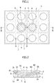
Fig. 1] Fig. 1 is a plan view schematically showing a liquid manipulation device according to a First Embodiment. - [
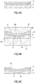
Fig. 2] Fig. 2 is a sectional view taken along line A-A ofFig. 1 . - [
Fig. 3] Figs. 3(a), (b), and (c) are sectional views schematically showing the liquid manipulation devices taken along line B-B ofFig. 1 , in a state before a droplet is moved, a state during the movement of the droplet, and a state after the droplet is moved, respectively. - [
Fig. 4] Figs. 4(a), (b), and (c) are sectional views schematically showing the liquid manipulation devices taken along line A-A ofFig. 1 , in a state before a dimple forming process, a state during the dimple forming process, and a state after the dimple forming process, respectively. - [
Fig. 5] Fig. 5 is a sectional view schematically showing a liquid manipulation device according to a Second Embodiment, taken along a line corresponding to the line A-A ofFig. 1 . - Liquid manipulation devices according to First and Second Embodiments are described below.
- As described herein, a "film" indicates an object having a layer shape and having a thickness of approximately 200 µm (micrometer) or less, and a "sheet" indicates an object having a layer shape and having a thickness exceeding approximately 200 µm.
- A liquid manipulation device according to a First Embodiment is described below.
- The liquid manipulation device according to the present Embodiment is described in outline with reference to
Figs. 1 and 2 . The liquid manipulation device includes asubstrate 1 having a sheet shape or a film shape so as to have flexibility. Thesubstrate 1 has aback surface 1a, and afront surface 1b located opposite theback surface 1a with respect to a thickness direction of thesubstrate 1. - The liquid manipulation device includes
electrodes 2 located on thefront surface 1b of thesubstrate 1. The liquid manipulation device includes aninsulating layer 3 located over thefront surface 1b of thesubstrate 1 so as to cover theelectrodes 2. The liquid manipulation device is configured to move liquid L, in particular, a droplet L, on afront surface 3b of theinsulating layer 3 by using an electrostatic force that is generated when voltage is applied to at least one of theelectrodes 2. Thefront surface 3b of theinsulating layer 3 is described below. - The insulating
layer 3 of the liquid manipulation device has aback surface 3a and thefront surface 3b. Theback surface 3a of the insulatinglayer 3 faces thefront surface 1b of thesubstrate 1. Thefront surface 3b of the insulatinglayer 3 is located opposite theback surface 3a of the insulatinglayer 3 with respect to a thickness direction of the insulatinglayer 3. The insulatinglayer 3 includesdimples 4 that are curved concave in a concave direction directed from thefront surface 3b of the insulatinglayer 3 toward theback surface 3a of the insulatinglayer 3. Thedimples 4 are located in correspondence with theelectrodes 2 respectively. Each of theelectrodes 2 includes a first dimple-correspondingportion 5 being curved concave in the concave direction together with one of thedimples 4 that is located in correspondence with the correspondingelectrode 2. - Furthermore, the
front surface 3b of the insulatinglayer 3 may be open to the outside. Each of theelectrodes 2 may be larger than the corresponding one of thedimples 4. - The
substrate 1 is described below in detail with reference toFigs. 1 and 2 . Thesubstrate 1 may be configured as described below. InFig. 2 , thesubstrate 1 includesconcave portions 1c that are concave in correspondence with theelectrodes 2 respectively. Thesubstrate 1 also includes second dimple-correspondingportions 6 that are concave in the concave direction in correspondence with the first dimple-correspondingportions 5 of theelectrodes 2 respectively. The second dimple-correspondingportion 6 is located within theconcave portion 1c. Theback surface 1a of thesubstrate 1 is smooth or flat. Alternatively, the substrate can be formed to include the second dimple-corresponding portions and include no concave portions. In that case, the electrodes may be placed on the substrate using, for example, a printer, such as an ink jet printer or the like. - The
substrate 1 may be made using paper, resin, and/or the like. As used herein, "paper" indicates a material fabricated by aggregating plant fibers, other fibers, and/or the like, and may include: an inorganic substance, such as a porous material and/or the like; and organic molecules, such as synthetic molecules added to it, and/or the like; and/or the like. As used herein, "resin" indicates a material including a natural and/or synthetic macromolecular compound as the principal component. The material may be a composite material that further includes fiber, an inorganic substance, and/or the like. In particular, thermoplastic resin which can be processed with heat easily, may be used. In particular, thesubstrate 1 may be bendable. Thesubstrate 1 may also be cuttable using a cutting tool, such as scissors, a cutter, and/or the like. - The thickness of the
substrate 1 is set such that thesubstrate 1 possesses flexibility. For example, when thesubstrate 1 is made using paper or is of paper, thesubstrate 1 can have a thickness of approximately 100 µm to approximately 200 µm. When thesubstrate 1 is made using or of resin, thesubstrate 1 may be a film having a thickness of approximately 200 µm or less. Alternatively, thesubstrate 1 made using or of resin, may be a sheet having a thickness exceeding approximately 200 µm. It is preferable that thesubstrate 1 not be made using glass or silicon. However, these are not limitations to the material and thickness of the substrate of the present invention. The thickness of thesubstrate 1 can be set such that thesubstrate 1 has flexibility and theback surface 1a of thesubstrate 1 remains smooth or flat at locations at which the second dimple-correspondingportions 6 are located even after the dimple forming process is performed to form thedimples 4 as described below. - The
electrodes 2 are described below in detail with reference toFigs. 1, 2 , and3(a) to 3(c). Theelectrode 2 may be configured as described below. Theelectrode 2 is made of a conductive material. The conductive material may be a material, such as metal, carbon, metallic oxide, a material containing at least one material among the materials set forth, or the like. Theelectrode 2 has a layer shape. The electrode can be formed using, for example, a conductive ink. The thickness of theelectrode 2 is set to allow plastic deformation of theelectrode 2 and the insulatinglayer 3 together during the dimple forming process, which will be described below. - The
electrode 2 has aback surface 2a and afront surface 2b. Theback surface 2a of theelectrode 2 faces thefront surface 1b of thesubstrate 1. Thefront surface 2b of theelectrode 2 is located opposite theback surface 2a of theelectrode 2 with respect to a thickness direction of theelectrode 2. Theelectrode 2 also includes aperimeter portion 2c located on the outer periphery of the first dimple-correspondingportion 5. Theperimeter portion 2c is located along thefront surface 1b of thesubstrate 1. - In
Fig. 2 , theelectrode 2 is located within theconcave portion 1c of thesubstrate 1 with thefront surface 2b of theelectrode 2 substantially coincident with thefront surface 1b of thesubstrate 1. If the substrate is formed to include the second dimple-corresponding portions and include no concave portions as described above, the perimeter portions of the electrodes can be located on the front surface of the substrate to protrude from the front surface of the substrate. - The
electrodes 2 are spaced apart from one another on thefront surface 1b of thesubstrate 1. Furthermore, theelectrodes 2 are arranged into a matrix with m rows and n columns on thefront surface 1b of thesubstrate 1. As used herein, m is an integer of 1 or greater, and n is an integer of 2 or greater. Alternatively, m is an integer of 2 or greater and n is an integer of 1 or greater. In an example inFig. 1 , 12electrodes 4 are arranged into a matrix with three rows and four columns. The arrangement of the electrodes is not limited to a matrix. The electrodes may be located such that a desired movement route intended for liquid can be provided. For example, the electrodes can be arranged into a honeycomb matrix in which the shapes of the electrodes are not limited to substantially hexagonal shapes. - As shown in
Figs. 3(a) to 3(c) , theelectrodes 2 are connected to a circuit C. The circuit C is configured to apply voltage to theelectrodes 2 individually. InFig. 1 , the circuit C is located outside thesubstrate 1. However, this is not a limitation to the present invention. At least a portion of the circuit may be located in the substrate. For example, wiring of the circuit, which is a portion of the circuit, may be located in the substrate. - In
Figs. 3(a) to 3(c) , the circuit C including a switch, a power supply, and grounding, is schematically shown as an example to describe states in which voltage is applied to theelectrodes 2 individually. The circuit connected to the electrodes, is not limited to the circuit C shown inFigs. 3(a) to 3(c) . The circuit can have any configuration as long as voltage can be applied to the electrodes individually to generate an electrostatic force for stopping and moving a droplet. - The insulating
layer 3 is described below in detail with reference toFigs. 1 and 2 . The insulatinglayer 3 may be configured as described below. The insulatinglayer 3 may be electrically insulating. The insulatinglayer 3, in particular, thefront surface 3b of the insulatinglayer 3, may be hydrophobic. The insulatinglayer 3 may thus be made using an electrically insulating and hydrophobic material. The material may be an electrically insulating and hydrophobic resin, for example, fluororesin or the like. The front surface of the insulating layer can be made using a hydrophobic material or an electrically insulating and hydrophobic material, and the remaining portion of the insulating layer can be made using an electrically insulating material. - Each of the
dimples 4 of the insulatinglayer 3 includes anopening portion 4a and anopening edge portion 4b. Theopening portion 4a is open in thefront surface 3b of the insulatinglayer 3. The openingedge portion 4b is located at the edge of theopening portion 4a, surrounding theopening portion 4a. The openingedge portion 4b has a substantially circular shape. However, the shape of the opening edge portion is not limited to a substantially circular shape. For example, the opening edge portion can have: a substantially polygonal shape, such as a substantially rectangular shape, a substantially hexagonal shape, or the like; a substantially elliptical shape; or the like. The opening edge portion can have a curved corner. - The
dimple 4 also includes abottom portion 4c facing theopening portion 4a in the thickness direction of the insulatinglayer 3 and being located toward theback surface 3a of the insulatinglayer 3 with respect to theopening portion 4a. Thedimple 4 also includes a surroundingwall portion 4d extending between the openingedge portion 4b and thebottom portion 4c. Thebottom portion 4c has a substantially arc shape that is concave in the concave direction. However, the shape of the bottom portion is not limited to a substantially arc shape. For example, the bottom portion can have a substantially flat shape. The bottom portion can have a substantially conic shape that is concave in the concave direction. - The surrounding
wall portion 4d becomes narrower toward thebottom portion 4c from the openingedge portion 4b. The surroundingwall portion 4d has a substantially arc shape that is concave in the concave direction. However, the shape of the surrounding edge portion is not limited to a substantially arc shape. For example, the surrounding wall portion can extend substantially straight between the opening edge portion and the bottom portion. - The
bottom portion 4c and the surroundingwall portion 4d of thedimple 4 that have substantially arc shapes concave in the concave direction, have curvatures that are substantially the same. Alternatively, the bottom portion and the surrounding wall portion that have substantially arc shapes, can have different curvatures. Furthermore, the maximum depth of thedimple 4, the size of the openingedge portion 4b of thedimple 4, the shape of thedimple 4, and the like are defined such that the liquid L, in particular, the droplet L, can be retained continuously and stably in a position in which thedimple 4 is located and the liquid L, in particular, the droplet L, fitted in thedimple 4, can be moved smoothly. - With reference to
Figs. 1 and3(a) to 3(c) , manipulation to move the droplet L in the liquid manipulation device according to the present Embodiment is described below. As shown inFigs. 1 and3(a) , the droplet manipulation device is in a first voltage application state in which a voltage is applied to one of theelectrodes 2, and a voltage lower than the voltage applied to the one of theelectrodes 2 or no voltage, is applied to the remainingelectrodes 2 orelectrodes 2 located in the vicinity of the one of theelectrodes 2. Due to an electrostatic force generated in the first voltage application state, and fitting of a droplet L in one of thedimples 4 that corresponds to the one of theelectrodes 2, the droplet L is retained continuously and stably in a first stop position in which the one of thedimples 4 is located. - As shown in
Fig. 3(b) , the droplet manipulation device is then in a second voltage application state in which a voltage is applied to another one of theelectrodes 2 located next to the one of theelectrodes 2, and a voltage lower than the voltage applied to the other one of theelectrodes 2 or no voltage is applied to the remainingelectrodes 2 orelectrodes 2 located in the vicinity of the other one of theelectrodes 2. Due to an electrostatic force generated in the second voltage application state, the droplet L located in the first stop position, is attracted to a second stop position in which another one of thedimples 4 that corresponds to the other one of the electrodes is located. The droplet L moves from the first stop position to the second stop position. - As shown in
Figs. 1 and3(c) , due to the electrostatic force generated in the second voltage application state and fitting of the droplet L in the other one of thedimples 4, the droplet L is then stopped at the second stop position reliably and retained in the second stop position continuously and stably. In particular, the droplet L moving from the first stop position to the second stop position, can be stopped at the second stop position reliably by the other one of thedimples 4, countering the inertial force of the droplet L. InFig. 1 , the droplet L is indicated by an imaginary line, which is a two-dot chain line. - With reference to
Figs. 4(a) to 4(c) , a method of forming thedimple 4 in the liquid manipulation device according to the present Embodiment, is described below. As shown inFig. 4(a) , in the liquid manipulation device in which thedimple 4 is to be formed, theelectrode 2 is placed on thesubstrate 1, and the insulatinglayer 3 is placed over thesubstrate 1 so as to cover theelectrode 2, while the insulatinglayer 3, theelectrode 2, and thesubstrate 1 are substantially flat. - As shown in
Fig. 4(b) , a process (hereinafter referred to as dimple forming process as required) is then performed on the liquid manipulation device in which thedimple 4 is to be formed. In the process, a lower mold D is brought into contact with theback surface 1a of thesubstrate 1, and an upper mold U is pressed onto thefront surface 3b of the insulatinglayer 3 with a predefined pressing pressure for a predefined pressing time. In the dimple forming process, the lower mold D has a contact surface d1 that is brought into contact with theback surface 1a of thesubstrate 1. The contact surface d1 of the lower mold D is substantially flat. The upper mold U has a contact surface u1 that is brought into contact with thefront surface 3b of the insulatinglayer 3. The contact surface u1 of the upper mold U includes convex portions u2 that correspond to thedimples 4 respectively. The process may be performed with the upper mold U heated to a predefined heating temperature. The pressing pressure, pressing time, and heating temperature of the dimple forming process may be adjusted such that thedimples 4 of the insulatinglayer 3 and the dimple-correspondingportions 5 of theelectrodes 2 can be plastically formed appropriately. The dimple forming process may be an embossing process, but this is not a limitation. - As shown in
Fig. 4(c) , when the upper mold U and the lower mold D are separated from the liquid manipulation device after the elapse of the predefined pressing time, thedimple 4 of the insulatinglayer 3 is curved concave in the concave direction. The dimple-correspondingportion 5 of theelectrode 2, is also curved concave in the concave direction together with thedimple 4 that is located in correspondence with theelectrode 2. Theback surface 1a of thesubstrate 1 remains smooth or flat. - As described above, in the liquid manipulation device according to the present Embodiment, the insulating
layer 3 includes thedimples 4 that are located in correspondence with theelectrodes 2 respectively and curved concave in the concave direction directed from thefront surface 3b of the insulatinglayer 3 toward theback surface 3a of the insulatinglayer 3. Each of theelectrodes 2 includes a dimple-correspondingportion 5 being curved concave in the concave direction together with one of thedimples 4 that is located in correspondence with the correspondingelectrode 2. Thus, liquid L can be stopped efficiently at a desired position on thefront surface 3b of the insulatinglayer 3 due to thedimple 4. The liquid manipulation device can thus have an enhanced ability to control the liquid L, in particular, a droplet L. Since each of theelectrodes 2 includes the dimple-correspondingportion 5 as described above, the dimple forming process to form thedimples 4, for example, an embossing process, in which the insulatinglayer 3, theelectrodes 2, and thesubstrate 1 are together pressed from thefront surface 3b of the insulatinglayer 3, can be performed with a large force to enable deformation of theelectrodes 2. As a result, thedimples 4 can be formed into desired shapes easily, whereby improved accuracy with which the liquid manipulation device is processed, can be provided. Thus, improved efficiency for fabricating the liquid manipulation device can be provided. - The
front surface 3b of the insulatinglayer 3 of the liquid manipulation device according to the present Embodiment is open to the outside. Thus, the liquid manipulation device has a simplified configuration on thefront surface 3b side of the insulatinglayer 3, whereby improved efficiency can be provided for fabricating the liquid manipulation device. - In the liquid manipulation device according to the present Embodiment, each of the
electrodes 2 is larger than the corresponding one of thedimples 4. Thus, when thedimples 4 are formed in the insulatinglayer 3 during the dimple forming process, for example, an embossing process, the dimple-correspondingportion 5 of theelectrode 2 can be formed to conform to thedimple 4 stably while theperimeter portion 2c of theelectrode 2, which is located closer to the outer periphery of thedimple 4 than to thedimple 4, is held. Thus, improved efficiency for fabricating the liquid manipulation device can be provided. - A liquid manipulation device according to a Second Embodiment is described below. The liquid manipulation device according to the present Embodiment is similar to the liquid manipulation device according to the First Embodiment except for the substrate. Constituent elements of the present Embodiment that are similar to those of the First Embodiment, are designated with the same reference signs as those of the First Embodiment.
- As shown in
Fig. 5 , the liquid manipulation device according to the present Embodiment includes asubstrate 11 that is similar to thesubstrate 1 of the First Embodiment, except for what is described below. Thesubstrate 11 includes aback surface 11a, afront surface 11b, and a concave portion 11c that correspond to theback surface 1a, thefront surface 1b, and theconcave portion 1c of thesubstrate 1 of the First Embodiment, respectively. Thesubstrate 11 includes second dimple-correspondingportions 16 that correspond to the second dimple-correspondingportions 6 of the First Embodiment. - Each of the dimple-corresponding
portions 16 of thesubstrate 11 is curved concave in the concave direction together with the dimple-correspondingportion 5 of one of theelectrodes 2 and one of thedimples 4 of the insulatinglayer 3, the one of theelectrodes 2 located in correspondence with the corresponding dimple-correspondingportion 16, the one of thedimples 4 located in correspondence with the corresponding dimple-correspondingportion 16. The second dimple-correspondingportion 16 is located within theconcave portion 1c. Theback surface 11a of thesubstrate 11 has portions that are convex at locations at which the second dimple-correspondingportions 16 are located, respectively. The thickness of thesubstrate 11 is set to allow plastic deformation of thesubstrate 11 together with theelectrodes 2 and the insulatinglayer 3 during the dimple forming process. - Manipulation to move a droplet L in the liquid manipulation device according to the present Embodiment, is similar to the manipulation to move the droplet L in the First Embodiment. A method of forming the
dimples 4 in the present Embodiment, while not specifically shown in a drawing, is similar to the method of forming the dimples in the First Embodiment, except that the lower mold has a contact surface including concave portions being respectively concave in correspondence with the second dimple-corresponding portions that are convex as described above. - In addition to operation and effects similar to those of the liquid manipulation device according to the First Embodiment, the liquid manipulation device according to the present Embodiment can provide operation and effects as described below. In the liquid manipulation device according to the present Embodiment, the
substrate 11 includes the dimple-correspondingportions 16 located in correspondence with thedimples 4 respectively. Each of the dimple-correspondingportions 16 of thesubstrate 11 is curved concave in the concave direction together with the dimple-correspondingportion 5 of one of theelectrodes 2 and one of thedimples 4 of the insulatinglayer 3, the one of theelectrodes 2 being located in correspondence with the corresponding dimple-correspondingportion 16, the one of thedimples 4 being located in correspondence with the corresponding dimple-correspondingportion 16. - Thus, the dimple forming process to form the
dimples 4, for example, an embossing process, in which the insulatinglayer 2, theelectrodes 2, and thesubstrate 11 are together pressed from thefront surface 3b of the insulatinglayer 3, can be performed with an even greater force to enable deformation of thesubstrate 11 in addition to theelectrodes 2. As a result, thedimples 4 can be formed into desired shapes easily, whereby improved accuracy with which the liquid manipulation device is processed, can be provided. Thus, improved efficiency for fabricating the liquid manipulation device, can be offered. - While some Embodiments of the present invention have been described above, the present invention is not limited to the aforementioned Embodiments and can be modified or changed based on the technical concept of the present invention.
- In use, the liquid manipulation device according to the present invention can be integrated in a device, such as a portable and disposable automated batch-type device, an assay device, and/or the like. Nonlimiting examples of such devices include: a reagent component sensor; a reagent formulation processing device; an automated reagent component selector; a closed microenvironment type isolated aseptic cell incubator; a synthesizer of artificial organs arranged per cell strain; and/or the like.
- 1, 11 ... Substrate, 1b, 11b ... Front surface, 2 ... Electrode, 3 ... Insulating layer, 3a ... Back surface, 3b ... Front surface, 4 ... Dimple, 5 ... First dimple-corresponding portion, 16 ... Second dimple-corresponding portion
Claims (4)
- A liquid manipulation device comprising:a substrate including a sheet shape or a film shape to have flexibility;a plurality of electrodes located on a front surface of the substrate; andan insulating layer located over the front surface of the substrate to cover the electrodes, whereinthe insulating layer has: a back surface facing the front surface of the substrate; and a front surface being located opposite the back surface of the insulating layer with respect to a thickness direction of the insulating layer,the liquid manipulation device is configured to move liquid on the front surface of the insulating layer by using an electrostatic force that is generated when voltage is applied to at least one of the electrodes,the insulating layer includes dimples that are located in correspondence with the electrodes respectively and are curved concave in a concave direction directed from the front surface of the insulating layer toward the back surface of the insulating layer, andeach of the electrodes includes a dimple-corresponding portion being curved concave in the concave direction together with one of the dimples that is located in correspondence with the corresponding electrode.
- The liquid manipulation device as claimed in claim 1, wherein
the front surface of the insulating layer is open to outside. - The liquid manipulation device as claimed in claim 1, wherein
each of the electrodes is larger than the corresponding one of the dimples. - The liquid manipulation device as claimed in claim 1, whereinthe substrate includes dimple-corresponding portions located in correspondence with the dimples respectively, andeach of the dimple-corresponding portions in the substrate is curved concave in the concave direction together with the dimple-corresponding portion in one of the electrodes and one of the dimples in the insulating layer, the one of the electrodes being located in correspondence with the corresponding dimple-corresponding portion in the substrate, the one of the dimples in the insulating layer being located in correspondence with the corresponding dimple-corresponding portion in the substrate.
Applications Claiming Priority (2)
| Application Number | Priority Date | Filing Date | Title |
|---|---|---|---|
| JP2018217609A JP6899588B2 (en) | 2018-11-20 | 2018-11-20 | Liquid control device |
| PCT/JP2019/044114 WO2020105488A1 (en) | 2018-11-20 | 2019-11-11 | Liquid manipulation device |
Publications (2)
| Publication Number | Publication Date |
|---|---|
| EP3885310A1 true EP3885310A1 (en) | 2021-09-29 |
| EP3885310A4 EP3885310A4 (en) | 2022-09-07 |
Family
ID=70774446
Family Applications (1)
| Application Number | Title | Priority Date | Filing Date |
|---|---|---|---|
| EP19887294.7A Withdrawn EP3885310A4 (en) | 2018-11-20 | 2019-11-11 | DEVICE FOR HANDLING LIQUIDS |
Country Status (6)
| Country | Link |
|---|---|
| US (1) | US20220001379A1 (en) |
| EP (1) | EP3885310A4 (en) |
| JP (1) | JP6899588B2 (en) |
| KR (1) | KR102522825B1 (en) |
| CN (1) | CN113056436B (en) |
| WO (1) | WO2020105488A1 (en) |
Family Cites Families (27)
| Publication number | Priority date | Publication date | Assignee | Title |
|---|---|---|---|---|
| JP2005030985A (en) * | 2003-07-09 | 2005-02-03 | Olympus Corp | Liquid feed treatment method and liquid feed treatment means |
| TWI262309B (en) * | 2004-12-31 | 2006-09-21 | Ind Tech Res Inst | Droplet controlling apparatus, manufacturing method, controlling method and digital flow inspection apparatus |
| GB0526230D0 (en) * | 2005-12-22 | 2006-02-01 | Eastman Kodak Co | Display devices |
| JP4760426B2 (en) | 2006-02-13 | 2011-08-31 | ソニー株式会社 | Optical element and lens array |
| JP4792338B2 (en) * | 2006-07-04 | 2011-10-12 | 株式会社日立製作所 | Liquid transfer device |
| WO2008007511A1 (en) | 2006-07-10 | 2008-01-17 | Hitachi High-Technologies Corporation | Liquid transfer device |
| JP2008197296A (en) * | 2007-02-13 | 2008-08-28 | Sony Corp | Electrowetting device and manufacturing method thereof |
| KR20080082811A (en) * | 2007-03-09 | 2008-09-12 | 성균관대학교산학협력단 | Carbon nanotube-containing transparent electrode and manufacturing method thereof |
| WO2010009463A2 (en) * | 2008-07-18 | 2010-01-21 | Advanced Liquid Logic, Inc. | Droplet operations device |
| KR20100100974A (en) * | 2007-12-23 | 2010-09-15 | 어드밴스드 리퀴드 로직, 아이엔씨. | Droplet actuator configurations and methods of conducting droplet operations |
| FR2933315B1 (en) * | 2008-07-07 | 2012-02-10 | Commissariat Energie Atomique | MICROFLUIDIC DEVICE FOR DISPLACING LIQUID |
| FR2935763B1 (en) * | 2008-09-09 | 2010-10-08 | Commissariat Energie Atomique | MICROFLUID MICROFLUIDIC CONTINUES |
| US8877512B2 (en) * | 2009-01-23 | 2014-11-04 | Advanced Liquid Logic, Inc. | Bubble formation techniques using physical or chemical features to retain a gas bubble within a droplet actuator |
| US9823221B2 (en) * | 2012-02-17 | 2017-11-21 | STRATEC CONSUMABLES GmbH | Microstructured polymer devices |
| DK2910604T3 (en) * | 2012-10-16 | 2022-05-16 | Daikin Ind Ltd | HIGH-ELECTRICAL FILM |
| US9630176B2 (en) * | 2013-01-09 | 2017-04-25 | Tecan Trading Ag | Microfluidics systems with waste hollow |
| GB2515571A (en) * | 2013-06-28 | 2014-12-31 | Ibm | Fabrication of microfluidic chips having electrodes level with microchannel walls |
| JP2016539343A (en) * | 2013-08-30 | 2016-12-15 | イルミナ インコーポレイテッド | Manipulating droplets on hydrophilic or mottled hydrophilic surfaces |
| JP2016109499A (en) * | 2014-12-04 | 2016-06-20 | パナソニックIpマネジメント株式会社 | Device and method for droplet driving device |
| JP2018518655A (en) * | 2015-04-03 | 2018-07-12 | アボット・ラボラトリーズAbbott Laboratories | Sample analysis device and method |
| WO2017083131A1 (en) * | 2015-11-09 | 2017-05-18 | Qorvo Us, Inc. | Baw sensor with enhanced surface area active region |
| US10434513B2 (en) * | 2016-06-08 | 2019-10-08 | Wisconsin Alumni Research Foundation | Method and device for containing expanding droplets |
| JP6494580B2 (en) * | 2016-09-28 | 2019-04-03 | シャープ ライフ サイエンス (イーユー) リミテッド | Microfluidic device |
| CN109952154B (en) * | 2018-06-26 | 2022-05-13 | 京东方科技集团股份有限公司 | Sample analysis chip and method for manufacturing same |
| MX2020014066A (en) * | 2018-12-17 | 2021-05-27 | Illumina Inc | Flow cells and sequencing kits. |
| JP7479606B2 (en) * | 2020-05-19 | 2024-05-09 | 国立研究開発法人産業技術総合研究所 | Method for producing a radioactive composition |
| US20230201823A1 (en) * | 2021-12-23 | 2023-06-29 | Rutgers, The State University Of New Jersey | Micromachined electroactive membranes with embedded microfluidic channels and methods of making and using the same |
-
2018
- 2018-11-20 JP JP2018217609A patent/JP6899588B2/en active Active
-
2019
- 2019-11-11 WO PCT/JP2019/044114 patent/WO2020105488A1/en not_active Ceased
- 2019-11-11 CN CN201980075612.8A patent/CN113056436B/en active Active
- 2019-11-11 KR KR1020217012126A patent/KR102522825B1/en active Active
- 2019-11-11 EP EP19887294.7A patent/EP3885310A4/en not_active Withdrawn
- 2019-11-11 US US17/290,568 patent/US20220001379A1/en not_active Abandoned
Also Published As
| Publication number | Publication date |
|---|---|
| KR102522825B1 (en) | 2023-04-18 |
| JP6899588B2 (en) | 2021-07-07 |
| KR20210064314A (en) | 2021-06-02 |
| CN113056436B (en) | 2024-12-13 |
| EP3885310A4 (en) | 2022-09-07 |
| CN113056436A (en) | 2021-06-29 |
| JP2020081937A (en) | 2020-06-04 |
| US20220001379A1 (en) | 2022-01-06 |
| WO2020105488A1 (en) | 2020-05-28 |
Similar Documents
| Publication | Publication Date | Title |
|---|---|---|
| Zheng et al. | Self‐powered electrostatic actuation systems for manipulating the movement of both microfluid and solid objects by using triboelectric nanogenerator | |
| CA2468334C (en) | Apparatus and methods for microfluidic applications | |
| EP2928606B1 (en) | Manipulation of objects in microfluidic devices using external electrodes | |
| JPWO2007094254A1 (en) | Microchannel chip and manufacturing method thereof | |
| WO2014108367A1 (en) | Disposable cartridge for microfluidics systems | |
| EP3435150A1 (en) | Electrowetting device and method of manufacturing electrowetting device | |
| Hale et al. | Electrowetting-based microfluidic operations on rapid-manufactured devices for heat pipe applications | |
| EP3498373B1 (en) | Microfluidic device and manufacturing method therefor | |
| US20050045539A1 (en) | Control device and method for controlling liquid droplets | |
| JP2007527505A (en) | Method for bonding microstructured substrates | |
| US20220001379A1 (en) | Liquid manipulation device | |
| CN110773247A (en) | A detection chip for trace samples | |
| US10954118B2 (en) | Device with a suspended membrane having an increased amplitude of displacement | |
| CN115151342A (en) | Substrate, microfluidic device, driving method, and manufacturing method | |
| Neog et al. | Electrical actuation of hydrophobic bilayer membranes of reduced graphene oxide and agar for inducing chemical reactions in microdroplets | |
| US20140054261A1 (en) | Micro-device on glass | |
| Ciou et al. | Microfluidic patterning using a digital microfluidic system | |
| WO2007060851A1 (en) | Method for fabricating barrier rib and substrate for electrophoretic display medium and electrophoretic display medium | |
| US11213821B2 (en) | Microfluidic device and manufacturing method therefor | |
| US20220126256A1 (en) | Open-type liquid manipulation device | |
| US20130210070A1 (en) | Microfluidic device and method for controlling interaction between liquids | |
| CN115007227B (en) | droplet manipulation method | |
| Chen et al. | A Digital Microfluidic Droplet Robotic System Enabled by Programmed Electrostatic Tweezer Arrays and Femtosecond Laser-Engineered Insulating Superhydrophobic Platforms | |
| Franco et al. | Bonding process using integrated electrothermal actuators for microfluidic circuit fabrication | |
| US20100175998A1 (en) | Virtual channel platform |
Legal Events
| Date | Code | Title | Description |
|---|---|---|---|
| STAA | Information on the status of an ep patent application or granted ep patent |
Free format text: STATUS: THE INTERNATIONAL PUBLICATION HAS BEEN MADE |
|
| PUAI | Public reference made under article 153(3) epc to a published international application that has entered the european phase |
Free format text: ORIGINAL CODE: 0009012 |
|
| STAA | Information on the status of an ep patent application or granted ep patent |
Free format text: STATUS: REQUEST FOR EXAMINATION WAS MADE |
|
| 17P | Request for examination filed |
Effective date: 20210519 |
|
| AK | Designated contracting states |
Kind code of ref document: A1 Designated state(s): AL AT BE BG CH CY CZ DE DK EE ES FI FR GB GR HR HU IE IS IT LI LT LU LV MC MK MT NL NO PL PT RO RS SE SI SK SM TR |
|
| DAV | Request for validation of the european patent (deleted) | ||
| DAX | Request for extension of the european patent (deleted) | ||
| A4 | Supplementary search report drawn up and despatched |
Effective date: 20220809 |
|
| RIC1 | Information provided on ipc code assigned before grant |
Ipc: B01L 3/00 20060101ALI20220803BHEP Ipc: B01J 19/00 20060101ALI20220803BHEP Ipc: G01N 35/08 20060101ALI20220803BHEP Ipc: G01N 37/00 20060101ALI20220803BHEP Ipc: B81B 1/00 20060101AFI20220803BHEP |
|
| STAA | Information on the status of an ep patent application or granted ep patent |
Free format text: STATUS: THE APPLICATION HAS BEEN WITHDRAWN |
|
| 18W | Application withdrawn |
Effective date: 20250801 |