EP3885264A1 - Thermostatically controlled galley air extraction - Google Patents
Thermostatically controlled galley air extraction Download PDFInfo
- Publication number
- EP3885264A1 EP3885264A1 EP21165691.3A EP21165691A EP3885264A1 EP 3885264 A1 EP3885264 A1 EP 3885264A1 EP 21165691 A EP21165691 A EP 21165691A EP 3885264 A1 EP3885264 A1 EP 3885264A1
- Authority
- EP
- European Patent Office
- Prior art keywords
- poppet
- coupled
- piston
- louver
- plenum chamber
- Prior art date
- Legal status (The legal status is an assumption and is not a legal conclusion. Google has not performed a legal analysis and makes no representation as to the accuracy of the status listed.)
- Granted
Links
Images



Classifications
-
- B—PERFORMING OPERATIONS; TRANSPORTING
- B64—AIRCRAFT; AVIATION; COSMONAUTICS
- B64D—EQUIPMENT FOR FITTING IN OR TO AIRCRAFT; FLIGHT SUITS; PARACHUTES; ARRANGEMENT OR MOUNTING OF POWER PLANTS OR PROPULSION TRANSMISSIONS IN AIRCRAFT
- B64D13/00—Arrangements or adaptations of air-treatment apparatus for aircraft crew or passengers, or freight space
-
- B—PERFORMING OPERATIONS; TRANSPORTING
- B64—AIRCRAFT; AVIATION; COSMONAUTICS
- B64D—EQUIPMENT FOR FITTING IN OR TO AIRCRAFT; FLIGHT SUITS; PARACHUTES; ARRANGEMENT OR MOUNTING OF POWER PLANTS OR PROPULSION TRANSMISSIONS IN AIRCRAFT
- B64D11/00—Passenger or crew accommodation; Flight-deck installations not otherwise provided for
- B64D11/04—Galleys
-
- F—MECHANICAL ENGINEERING; LIGHTING; HEATING; WEAPONS; BLASTING
- F16—ENGINEERING ELEMENTS AND UNITS; GENERAL MEASURES FOR PRODUCING AND MAINTAINING EFFECTIVE FUNCTIONING OF MACHINES OR INSTALLATIONS; THERMAL INSULATION IN GENERAL
- F16K—VALVES; TAPS; COCKS; ACTUATING-FLOATS; DEVICES FOR VENTING OR AERATING
- F16K15/00—Check valves
-
- B—PERFORMING OPERATIONS; TRANSPORTING
- B64—AIRCRAFT; AVIATION; COSMONAUTICS
- B64D—EQUIPMENT FOR FITTING IN OR TO AIRCRAFT; FLIGHT SUITS; PARACHUTES; ARRANGEMENT OR MOUNTING OF POWER PLANTS OR PROPULSION TRANSMISSIONS IN AIRCRAFT
- B64D13/00—Arrangements or adaptations of air-treatment apparatus for aircraft crew or passengers, or freight space
- B64D13/06—Arrangements or adaptations of air-treatment apparatus for aircraft crew or passengers, or freight space the air being conditioned
- B64D2013/0603—Environmental Control Systems
- B64D2013/0655—Environmental Control Systems with zone or personal climate controls
Definitions
- the system includes an actuating assembly.
- the actuating assembly includes a cylinder.
- the actuating assembly includes a heat-expanding material that is disposed within the cylinder.
- the actuating assembly includes a piston disposed within the cylinder.
- the heat-expanding material is configured to actuate the piston when the heat-expanding material is heated.
- the actuating assembly includes a piston seal.
- the system includes a valve assembly coupled to the actuating assembly and disposed upon at least one of a surface of the galley compartment or a face of the plenum chamber. In some embodiments, an adjustment of the valve by the actuating assembly adjust airflow within an opening of the at least one of the surface of the galley compartment or the face of the plenum chamber. In some embodiments, the actuating assembly further includes a return spring seated at one end at the piston and its opposite end at a retaining surface proximate to an open face of the cylinder. In some embodiments, a compressive force of the return spring upon the piston at least partially counteracts the force of the heat-expanding material on the piston.
- the valve assembly further includes a connecting rod. In some embodiments, a first end of the connecting rod is coupled to the piston. In some embodiments, the valve assembly further includes a louver assembly coupled to a second end of the connecting rod. In some embodiments, the louver assembly includes a louver frame. In some embodiments, the louver assembly includes one or more louver blades disposed within the louver frame. In some embodiments, the louver assembly includes a bracket coupled to the louver frame and the connecting rod. In some embodiments, an articulation of the connecting rod causes a movement of one or more louver blades. In some embodiments, the movement of one or more louver blades adjusts an airflow within an opening of at least one of the surface of the galley compartment or the face of the plenum chamber.
- the heat-expanding material is configured of at least one of a wax, a gel, or a copolymer.
- the one or more louver blades are configured to pivot relative to the louver frame upon the articulation of the connecting rod.
- the one or more louver blades are configured to reciprocate along the surface of at least one of the galley compartment or the face of the plenum chamber upon the articulation of the connecting rod, wherein the reciprocation adjusts airflow within the opening of at least one of the surface of the galley compartment or the face of the plenum chamber.
- the one or more louver blades are configured to rotate along a rotation axis, wherein the rotation adjusts airflow within the opening of at least one of the surface of the galley compartment or the face of the plenum chamber.
- system further includes an air bleed pathway configured to allow air from the galley compartment to contact the heat-expanding material.
- the valve assembly is disposed within a plenum chamber.
- the valve assembly further includes a poppet valve.
- the poppet valve comprises a poppet body seat coupled to an open face of the cylinder.
- the poppet body seat is coupled to at least one of the surface of the galley compartment or the face of the plenum chamber.
- the poppet valve further includes a poppet stem coupled to the piston.
- the poppet stem is inserted into a channel formed in the poppet body seat.
- the poppet valve includes a poppet head coupled to the poppet stem. In some embodiments, the movement of the poppet head adjusts an airflow within an opening of at least one of the surface of the galley compartment or the face of the plenum chamber.
- the heat-expanding material is at least one of a wax, a gel, or a copolymer.
- system further comprises an air bleed pathway configured allow air from the galley compartment to contact the heat-expanding material.
- the air bleed pathway is further configured to move air through one or more air bleed holes within the poppet head.
- system further includes a bellow chamber configured to improve airflow through the valve assembly.
- the valve assembly is coupled to at least one end of a hose or a manifold.
- the system includes at least one actuating assembly coupled to a valve assembly containing a louver assembly and at least one actuating assembly coupled to a valve assembly containing a poppet valve.
- a letter following a reference numeral is intended to reference an embodiment of the feature or element that may be similar, but not necessarily identical, to a previously described element or feature bearing the same reference numeral (e.g., 1, 1a, 1b).
- reference numeral e.g. 1, 1a, 1b
- Such shorthand notations are used for purposes of convenience only and should not be construed to limit the disclosure in any way unless expressly stated to the contrary.
- any reference to “one embodiment” or “some embodiments” means that a particular element, feature, structure, or characteristic described in connection with the embodiment is included in at least one embodiment disclosed herein.
- the appearances of the phrase “in some embodiments” in various places in the specification are not necessarily all referring to the same embodiment, and embodiments may include one or more of the features expressly described or inherently present herein, or any combination of sub-combination of two or more such features, along with any other features which may not necessarily be expressly described or inherently present in the instant disclosure.
- the embodiments of the inventive concepts disclosed herein are directed to devices within a galley, such as an aircraft or train galley, where food is prepared that regulate the movement of air between the galley and an air extraction system (e.g., an aircraft galley ventilation system).
- a galley such as an aircraft or train galley
- food is prepared that regulate the movement of air between the galley and an air extraction system (e.g., an aircraft galley ventilation system).
- an air extraction system e.g., an aircraft galley ventilation system
- Many commercial passenger transport vehicles have galleys and/or galley monuments that have multiple food preparation appliances installed. Many of these food preparation appliances produce large amounts of heat, including appliances such as ovens, refrigerators, and beverage makers. The heat generated from these appliances may be detrimental to the electronic componentry and other aspects of the operation of the appliance. The heat also increases the overall temperature of the air in the galley, possibly causing discomfort to staff and/or passengers, and may also exceed mandated maximum surface touch temperatures on the appliance surface.
- the appliances within the galley also may generate odors that are unpleasant to staff and/or passengers.
- galley air extraction systems have been created to remove the offending air from the galley. Many of these extraction systems involve ductwork that hold air at a lower pressure than air within the galley. Vents built into the interface between the galley and air extraction system allow hot and/or odiferous air to be removed into the ductwork, where it may be either expelled or retained within another area in the vehicle.
- vents within the air extraction systems can be problematic. Newer generations of appliances, particularly food and/or beverage heating devices, tend to generate more heat than previous devices which cannot be adequately be removed by the original vents. This increase in heat may also require an increase in airflow by the air extraction system, which may not be possible due to limits in the design of the air extraction system. If an increased air flow is achieved, the increased air flow during times when the galley is not in use is a wasted energy.
- the embodiments of the inventive concepts disclosed herein are intended as airflow devices that automatically controls flow of air from the galley into the air extraction system on a need basis. The devices are dependent on a temperature sensitive material that expands when heat is applied. The devices operate on an "on demand" basis, do not require any electrical or electronic equipment, and may be retrofitted on any commercial aircraft with an air handling system.
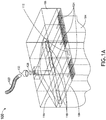
- FIG.1A and FIG.1B illustrate an example environment 100 for a system for controlling airflow from a galley compartment to an adjoining plenum chamber, in accordance with one or more embodiments of this disclosure.
- the example environment 100 includes one or more galley compartments 104.
- the galley compartment 104 houses heat-producing appliances of the galley, including but not limited to ovens, refrigerators, and beverage makers.
- the galley compartment 104 may also include areas used by galley staff to perform food preparation tasks.
- the example environment may also include one or more standard unit compartments 106 used for galley storage and/or meal storage. Air from the galley compartment 106 may or may not freely flow back and forth from the galley compartment 104
- the example environment 100 further includes a plenum chamber 108 disposed adjacent to the galley compartment 104.
- the plenum chamber 108 is pressurized at a lower pressure than the galley compartment.
- the plenum chamber 108 may be of any size or shape.
- the plenum chamber 108 may be a wide and relatively flat structure that is disposed upon the galley compartment 104 (e.g., as in FIG. 1A ).
- the example environment includes one or more openings 112 that connects the galley compartment 104 to the plenum chamber 108, allowing airflow between the two compartments. Since the air pressure in the galley compartment 104 is higher than the air pressure in the plenum chamber 108, air will flow through the opening 112 from the galley compartment 104 into the plenum chamber 108 unless the opening is obstructed.
- the galley compartment 104 and the plenum chamber 108 are adjoining.
- at least one surface of the galley compartment 104 may be immediately flush, or is a part of, a least one surface of the plenum chamber 108.
- the opening 112 would comprise a hole that matches between the two surfaces, allowing air to pass between the galley compartment 104 and the plenum chamber 108.
- the adjoining surfaces of the galley compartment 104 and the plenum chamber 108 is a simple flat surface.
- the adjoining surface may be a complex surface.
- an extension e.g., a pipe
- the plenum chamber 108 may be coupled to a manifold 116.
- the manifold 116 is a structure that directs air from the plenum chamber 108 into other componentry of the air extraction system of the aircraft (e.g., to a discharge port).
- the manifold may be of any size or shape.
- the manifold 116 may be a triangular structure set toward the rear of the plenum chamber 108.
- air may enter the manifold from the plenum chamber 108 via a vent 118 within the manifold 116.
- the manifold 116 may be coupled to an extraction hose 120. The extraction hose assists in directing air from the extraction compartment to the other componentry of the air extraction system.
- the extraction hose 120 is coupled directly to the manifold 116 via a port 122.
- a bellow chamber 123 is used to couple the extraction hose 120 to the port 122 of the manifold 116
- the extraction hose is omitted (e.g., the plenum chamber is directly coupled to other componentry of the air extraction system).
- the system includes a valve assembly configured to control airflow through the opening 112 or the port.
- the valve assembly is a louver-type valve assembly 124 (e.g., shown in FIG. 1A as covering openings 112.
- the valve assembly is a poppet-style valve assembly 128 (e.g., a 'mushroom' valve).
- FIG. 1B is a diagram illustrating a rear-view of a second example environment 150 of a system for controlling airflow from a galley compartment 104 to a plenum chamber 108, in accordance with one or more embodiments of this disclosure.
- the second example environment 150 is configured with one or more, or all components of the example environment 100, and vice-versa.
- the manifold 116 directly receives air from the galley compartment 104 via the louver-type valve assembly 124 (i.e., the manifold is acting as a de facto plenum chamber 108 as in FIG. 1B . Air then travels through the port 122 via the poppet-style valve assembly 128.
- an extraction hose 120 may connect directly to the port 122 or may use a bellow chamber 123 to couple to the port 122.
- an adapter duct 154 may be used to couple the extraction hose 120 to the port 122. It should be known that air extraction systems that have separate plenum chamber 108 and manifold 116 sections may have vents 118 that are controlled by a louver-style valve assembly 124. Therefore, the above description should not be interpreted as a limitation of the present disclosure, but merely as an illustration.
- the louver-type valve assembly 124 and the poppet-style valve assembly 128 may also be installed in many different configurations.
- the louver-type valve assembly 124 and/or the poppet-style valve assembly 128 may be installed on a wall (e.g., a vertically oriented wall), on a ceiling, or on a floor).
- the louver-type valve assembly 124 and/or the poppet-style valve assembly 128 may be installed on either an interior surface or an exterior surface of the galley compartment 104 or the plenum chamber 108. Therefore, the above description should not be interpreted as a limitation of the present disclosure, but merely as an illustration.
- the louver-type valve assembly 124 and the poppet-style valve assembly 128 are used together in within an air extraction system (e.g., such as in the example environments 100, 150).
- the poppet-style valve assembly 128 may be used to control the total gallery airflow, while the louver-type valve assembly 124 may be used to control the extraction of or air near each individual appliance.
- either the louver-style valve assembly 124 or the poppet-style valve assembly 128 may be used (i.e., the assemblies may work independently of each other). Therefore, the above description should not be interpreted as a limitation of the present disclosure, but merely as an illustration.
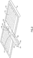
- FIG. 2 illustrates an actuating assembly coupled to a louver-type valve assembly 124, in accordance with one or more embodiments of this disclosure.
- the louver-type valve assembly 124 includes an actuating assembly 200.
- the actuating assembly 200 is configured to provide a motive force upon an increase in temperature (i.e. the actuating assembly 200 is a mechanical actuator used to provide unidirectional force through a unidirectional stroke, acting similarly to a hydraulic cylinder).
- the actuating assembly 124 includes a cylinder 204.
- the cylinder 204 is a hollow tube with one open end that houses componentry of the actuating assembly 200.
- the cylinder 204 may also provide a resistance for the components of the actuating assembly to act upon, resulting in a motive force.
- the cylinder 204 may be of any shape and size known in the art that can provide a unidirectional force.
- the cylinder 204 may have the external shape of a traditional cylinder shape.
- the cylinder 204 may have one or more flat surfaces along its external length. Therefore, the above description should not be interpreted as a limitation of the present disclosure, but merely an illustration.
- the actuating assembly 200 further includes a heat-expanding material 208 disposed within the cylinder 204.
- the heat-expanding material 208 changes volume over a range of temperatures (typically, the volume expands when heat is applied). Expansion of the heat-expanding material 208 pushes against all interior surfaces of the cylinder 204, delivering a motive force that can articulate movement.
- the heat-expanding material 208 may be any material known in the art, including but not limited to a wax or a gel.
- the heat-expanding material gel may be a copolymer gel.
- the copolymer gel may be dimethylaminoethyl methacrylate.
- the heat-expanding material 208 may be a paraffin-based wax.
- the heat-expanding material 208 should be certified as safe to use by the relevant authorities.
- the heat-expanding material may be compliant to Registration, Evaluation, Authorization, and Restriction of Chemicals (REACH) regulations of the European Union.
- the heat-expanding material 208 may respond to any range of temperatures.
- the heat-expanding material 208 may be response to a temperature between 15°C and 40°C.
- the actuating assembly 200 includes a piston 212.
- the piston 212 is a disk closely fitting within the cylinder 204 in which the piston moves up or down within the cylinder 204, depending on the expansion of the heat-expanding material 208 (e.g., the piston traps the heat-expanding material within the cylinder 204.)
- the piston seal is an O-shaped structure disposed upon the circumference of the piston, further providing a seal between the circumference of the piston 212 and the inner side wall of the cylinder 204.
- the actuating assembly includes a return spring 214 disposed between the piston and a side wall of the cylinder 204 (not shown in FIG. 2 ).
- the return spring 214 provides a countering force to the heat-expanding material 208, pushing the piston to a default position when the heat-expanding material 208 has cooled.
- the return spring can be any spring known in the art, including but not limited to a compression spring.
- the return spring 214 is seated with one end at the piston 212 and the opposite end at a retaining surface proximate to an open face of the cylinder 204.
- the open end of the cylinder 204 may be partially occluded within its circumference, allowing space for the connecting rod 220 to be inserted, while allowing a surface for the return spring 214 to push against.
- the connecting rod 220 is inserted through the return spring 214.
- one or more return springs 214 are utilized with each return spring 214 seated with one end at the piston 212 and the other end at the cylinder surface. Many configurations for the return spring 214 within the louver-style assembly are possible. Therefore, above description should not be interpreted as a limitation of the present disclosure, but merely as an illustration.
- the actuating assembly 200 and/or the louver-style valve is configured to bleed air through the surface of the galley compartment 104 and/or the face of the plenum chamber 108 (e.g., most aircraft systems are intended to extract air constantly, and therefore air may be bled through the valve constantly).
- air e.g., through an air bleed pathway
- the space within and immediately surrounding the actuating assembly will mix rapidly with the surrounding air (e.g., such as air near heat producing appliances), further exposing the heat-expanding material 208 to the air and decreasing the response time of the actuating assembly 200.
- the air may bleed directly from one or more small holes (e.g., holes considerably smaller than the openings 112) formed in at least one of the surface of the galley compartment or the face of the plenum chamber. Air flowing through these holes may come into contact with the cylinder 204 (e.g., the underside of the cylinder 204 in FIG. 2 ), or other components of the actuating assembly 200.
- small holes e.g., holes considerably smaller than the openings 112
- Air flowing through these holes may come into contact with the cylinder 204 (e.g., the underside of the cylinder 204 in FIG. 2 ), or other components of the actuating assembly 200.
- the actuating assembly includes a deflector 216.
- the deflector 216 increases the circulation of air to the heat-expanding material 208 within the cylinder 204.
- the one or more small holes formed in the surface of the galley compartment or the face of the plenum chamber that allows air to come into contact with the cylinder 204 may be further deflected by the deflector 216 further distributing the air throughout the length of the cylinder 204, allowing the air to heat and/or cool the heat-expanding material 208 within the cylinder 204.
- the louver-style valve assembly 124 includes a connecting rod 220 and a bracket 224.
- the connecting rod is coupled to the piston 212 on one end, and the bracket 224 on the other end.
- expansion of the heat-expanding material 208 through the addition of heat pushes the piston 212 towards the opening within the cylinder 204.
- the connecting rod 220 is articulated along with the piston, which then articulates the bracket 224.
- the movement of the connecting rod may be any range of movement needed to adjust the constriction of the opening. For example, the movement may be up to one centimeter. In another example, the movement may be up to 5 centimeters.
- the louver-style valve assembly 124 includes a louver assembly 228.
- the louver assembly 228 includes a louver frame 232 and one or more louver blades 236.
- the louver frame 232 provides a housing for the louver blades 236 and provides the mechanism for the coordinated movement of the louver blades 236.
- the louver frame also provides an attachment point for the bracket 224.
- the louver blades 236 are disposed at or near the one or more openings 112. Adjustment of the louver blades (e.g., through movement of the bracket articulated through the action of the articulation assembly) adjust the airflow through the opening.
- the mechanism of articulation of the louver blades 236 may be any mechanism known in the art.
- the louver blades 236 may be configured to rotate relative to the louver frame 232 along a rotational axis (e.g., along the long axis, as in a venetian blind) when the bracket 224 is articulated. In this manner, the rotation of the louver blades 236 may seal the opening 112 shut when the louver blades 236 are arranged in a single plane (e.g., the flat side of each louver blade 236 contacting or nearly contacting the flat end of another louver blade 236).
- the louver blades 236 may reopen through another rotation of the blades (e.g., a rotation that allows the flat side of the louver blades 236 to assume a position perpendicular to the face of the plenum chamber 108 and/or surface of the galley compartment 104).
- the louver blades 236 are configured to pivot relative to the louver frame 232 upon the articulation of the connecting rod 220,
- the louver blades 236 may be configured to reciprocate along the surface of at least one of the surface of the galley compartment 104 or the face of the plenum chamber 108 (e.g., slide along the surface).
- the louver blades 236 may be configured to form a slotted plate configured to cover openings 112 (e.g., openings in the form of slots or holes). Upon a sliding movement of the slotted plate, the constriction of the openings 112 are adjusted along with airflow through the openings 112.
- the louver-style valve assembly may also include a fixed grill body (e.g., containing slots and or holes) that is disposed over one or more openings 112, where the slots and or holes may be blocked or unblocked by the movement of the slotted plate.
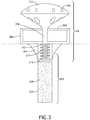
- FIG. 3 illustrates an actuating assembly 200 coupled to a poppet-type valve assembly 128, in accordance with one or more embodiments of this disclosure.
- the actuating assembly 200 of the poppet-style valve assembly 128 includes a cylinder 204.
- the actuating assembly 200 further includes a heat-expanding material 208.
- the actuating assembly further includes a piston 212.
- the actuating assembly includes a piston seal.
- the cylinder 204, heat-expanding material 208, piston 212 and piston seal of the actuating assembly 200 coupled to the poppet-type valve assembly 128 are similarly structured and have similar actions as that of the actuating assembly 200 of the louver-style valve assembly 124.
- the actuating assembly 200 coupled to the louver-style valve assembly 124 and the poppet-style valve assembly 128 have similar function and componentry (e.g., the heat-expanding material 208 and the cylinder 204). Therefore, the reference labels for the actuating assemblies 200 and the components of the actuating assemblies 200 coupled to the louver-style valve assembly 124 and the poppet-style valve assembly 128 have been replicated in the interest of clarity
- the poppet-type valve assembly 128 includes a poppet body element 300.
- the poppet body element 300 provides a structure to anchor the poppet-type valve assembly 128 to the surface of the galley compartment 104 and/or the face of the plenum chamber 108 (e.g., as indicated by the dotted line). It should be known that the poppet body element 300 may be disposed above, below, or incorporated into the surface of the galley compartment and/or the face of the plenum chamber 108, the manifold 116, or other ducts. Therefore, the above description should not be interpreted as a limitation of the present disclosure, but merely as an illustration.
- the poppet body element 300 is coupled to the open end of the cylinder 204.
- the poppet body element 300 may be coupled to the cylinder 204 (e.g., with bolts or screws) with the surface of the galley compartment 104 or face of the plenum chamber 108 sandwiched between the poppet body element 300 and the cylinder 204 (e.g., the poppet body element 300 is disposed upon or within the opening 112 or port 122 to either the surface of the galley compartment 104 or the face of the plenum chamber 108).
- the poppet body element 300 and the cylinder 204 are directly coupled.
- the poppet-type valve assembly 128 includes a gusset 304. The gusset stabilized the coupling between the poppet body element 300 and the cylinder 204.
- FIG. 4 is a diagram illustrating an underside view of the actuating assembly 200 coupled to the poppet-style valve assembly 128, in accordance with one or more embodiments of this disclosure.
- This underside plan view illustrates an underside surface of the poppet body element 300 that interacts with the face of the cylinder.
- the underside surface of the poppet body element 300 contains several apertures 305 that allow air to flow from the galley compartment 104 into the poppet body element 300.
- the underside surface of the poppet further contains crossmembers 306 that support the poppet body element 300 and are configured to form a shaft for a poppet stem 308 to slide through (e.g., the poppet stem 308 as shown in FIG. 3 ).
- the crossmembers 306 are further supported by one more gussets 304.
- the gussets 304 and the crossmembers 306 are configured as a single entity (e.g., the gusset 304 extends into the poppet body element 300, forming the crossmembers 306).
- the actuating assembly 200 of the poppet-type valve assembly 128 further includes a return spring 214.
- the spring provides a force upon the piston that is opposite of the motive force of the heat-expanding material 208 (i.e., when the heat-expanding material 208 shrinks due to a loss of heat, the return spring 214 assists in pushing the piston towards the shrinking heat-expanding material 208.
- the spring is seated with one end at the piston and the opposite end at the poppet body element 300.
- the spring 214 is seated with one end at the piston 212 and the opposite end at the surface of the galley compartment or the face of the air exchange compartment.
- the poppet-style valve assembly 128 further includes the poppet head 312 and the aforementioned poppet stem 308.
- the poppet stem 308 is coupled with one end to the piston 212, with the opposite end coupled to the poppet head 312.
- the poppet stem 308 is inserted into a channel 316 formed within the poppet body element 300 (e.g., formed by the crossmembers 306 and/or gussets 304).
- the poppet stem 308 is inserted through the center of the return spring 214.
- the poppet-style valve assembly 128 further includes a poppet seat 320.
- the poppet seat 320 seals off airflow when the poppet-style valve assembly 128 is in the closed position (e.g., when the poppet head 312 is seated against the poppet body element 300).
- the poppet head 312 is removed from the poppet seat 320, allowing air from the galley compartment 104 to enter the plenum chamber 108 through the apertures 305.
- the actuating assembly 200 and the poppet-style valve 128 is configured to bleed air through the surface of the galley compartment 104 and/or the face of the plenum chamber 105 (e.g., through an air bleed pathway). By bleeding a small amount of air, the space within and immediately surrounding the actuating assembly 200 will mix rapidly with the surrounding air (e.g., such as air near heat producing appliances), further exposing the heat-expanding material 208 to the air and decreasing the response time of the actuating assembly 200.
- the surrounding air e.g., such as air near heat producing appliances
- the poppet head 312 further contains one or more bleed holes 326.
- the one or more bleed holes 326 assist is moving a small amount of air through the components of the actuating assembly 200 and the poppet-like valve assembly 128. The movement of air assists in exposing the heat-expanding material 208 to the surrounding air, increasing the rapidity of the heat-expanding material to respond to a change in temperature.
- the air enters the bleed holes 326 from the poppet body element 300. An arrangement of bleed holes is illustrated in FIG. 5 .
- air from the plenum chamber 108 may flow into the poppet body element 300 (e.g., through the apertures 305), through the entrance of the one or more bleed holes 326 on the underside of the poppet head 312, and flow out of the poppet head 312 via the exit of the one of more bleed holes 326 into the adapter duct 154.
- the arrangement of bleed holes may be any arrangement that allow the flow of bleed air out from the poppet head. Therefore, the above description should note be interpreted as a limitation of the present disclosure, but merely an illustration.
- louver-type valve assembly 124 and the poppet-style valve assembly 128 allow efficient control of galley without overtaxing the aircraft air extraction system.
- a louver-style valve assembly 124 located near an oven may cause the heat-expanding material 208 within the actuating assembly 200 of the louver-type valve assembly to actuate when the oven has warmed the surrounding air after cooking a meal, while a separate louver-style valve assembly 124 near a nonoperating toaster may stay closed if the surrounding air is not hot enough to actuate the actuating assembly of the louver-style valve assembly 124.
- louver-style valve assemblies 124 The ability of the louver-style valve assemblies 124 to selectively open increases the airflow at the section of the galley compartment 104 with the heated air to the plenum chamber 108. Once air within the plenum chamber has been heated sufficiently, the poppet-style valve assembly will actuate, and a larger volume of air can be extracted from the galley compartment.
- the stepwise use of louver-style valve assemblies 124 and poppet-style valve assemblies 128 allow the extraction of air from specific portions of the galley compartment and ensure that overall air extraction is only turned on when necessary. This control of air extraction from the galley compartment may allow the aircraft air extraction system to more effectively remove air from other areas of the aircraft, such as the lavatory.
- any arrangement of components to achieve a same functionality is effectively “associated” such that the desired functionality is achieved, such that any two components herein combined to achieve a particular functionality can be seen as “associated with” each other (irrespective of architectures or intermedial components).
- Any two components so associated can also be viewed as being “operably connected” or “operably coupled” to each other to achieve the desired functionality, and any two components capable of being so associated can also be viewed as being “operably coupleable” to each other to achieve the desired functionality.
- Examples of operably coupleable include, but are not limited to, physically mateable and/or physically interacting components, wirelessly interactable and/or wirelessly interacting components, logically interacting and/or logically interactable components, or the like.
- one or more components may be referred to herein as “configured to,” “configurable to,” “operable/operative to,” “adapted/adaptable,” “able to,” “conformable/conformed to,” etc.
- configured to can generally encompass active-state components and/or inactive-state components and/or standby-state components, unless context requires otherwise.
Landscapes
- Engineering & Computer Science (AREA)
- Aviation & Aerospace Engineering (AREA)
- General Engineering & Computer Science (AREA)
- Health & Medical Sciences (AREA)
- General Health & Medical Sciences (AREA)
- Pulmonology (AREA)
- Mechanical Engineering (AREA)
- Air-Flow Control Members (AREA)
Abstract
Description
- In commercial aircraft with galley monuments installed, it is common to have beverage makers, ovens, refrigerators, and other galley insert equipment installed for the purpose of providing a catering service for passengers. All of these appliances produce waste heat and odors when in use. It is common to extract the air from around these appliances using an aircraft-based galley extraction system for cooling and environmental purposes. However, if the capacity of the galley extraction systems is overloaded by a large number of appliances installed within the aircraft, or if the extraction system operates regardless of whether the appliances are in operation or not, then it may not be possible to extract the minimum standard volumes of air at each individual appliance, possibly resulting in overheating of the appliances, increased working temperatures for aircraft staff and passengers, surface touch temperatures exceeding the mandatory maximum requirements, and the escape of cooking odors. Therefore, it would be advantageous to provide a solution that cures the shortcomings described above.
- A system for controlling airflow from a galley compartment to a plenum chamber is disclosed. In some embodiments, the system includes an actuating assembly. In some embodiments, the actuating assembly includes a cylinder. In some embodiments, the actuating assembly includes a heat-expanding material that is disposed within the cylinder. In some embodiments, the actuating assembly includes a piston disposed within the cylinder. In some embodiments, the heat-expanding material is configured to actuate the piston when the heat-expanding material is heated. In some embodiments, the actuating assembly includes a piston seal. In some embodiments, the system includes a valve assembly coupled to the actuating assembly and disposed upon at least one of a surface of the galley compartment or a face of the plenum chamber. In some embodiments, an adjustment of the valve by the actuating assembly adjust airflow within an opening of the at least one of the surface of the galley compartment or the face of the plenum chamber. In some embodiments, the actuating assembly further includes a return spring seated at one end at the piston and its opposite end at a retaining surface proximate to an open face of the cylinder. In some embodiments, a compressive force of the return spring upon the piston at least partially counteracts the force of the heat-expanding material on the piston.
- In some embodiments of the system, the valve assembly further includes a connecting rod. In some embodiments, a first end of the connecting rod is coupled to the piston. In some embodiments, the valve assembly further includes a louver assembly coupled to a second end of the connecting rod. In some embodiments, the louver assembly includes a louver frame. In some embodiments, the louver assembly includes one or more louver blades disposed within the louver frame. In some embodiments, the louver assembly includes a bracket coupled to the louver frame and the connecting rod. In some embodiments, an articulation of the connecting rod causes a movement of one or more louver blades. In some embodiments, the movement of one or more louver blades adjusts an airflow within an opening of at least one of the surface of the galley compartment or the face of the plenum chamber.
- In some embodiments of the system, the heat-expanding material is configured of at least one of a wax, a gel, or a copolymer.
- In some embodiments of the system, the one or more louver blades are configured to pivot relative to the louver frame upon the articulation of the connecting rod.
- In some embodiments of the system, the one or more louver blades are configured to reciprocate along the surface of at least one of the galley compartment or the face of the plenum chamber upon the articulation of the connecting rod, wherein the reciprocation adjusts airflow within the opening of at least one of the surface of the galley compartment or the face of the plenum chamber.
- In some embodiments of the system, the one or more louver blades are configured to rotate along a rotation axis, wherein the rotation adjusts airflow within the opening of at least one of the surface of the galley compartment or the face of the plenum chamber.
- In some embodiments of the system, the system further includes an air bleed pathway configured to allow air from the galley compartment to contact the heat-expanding material.
- In some embodiments of the system, the valve assembly is disposed within a plenum chamber.
- In some embodiments of the system, the valve assembly further includes a poppet valve. In some embodiments, the poppet valve comprises a poppet body seat coupled to an open face of the cylinder. In some embodiments, the poppet body seat is coupled to at least one of the surface of the galley compartment or the face of the plenum chamber. In some embodiments, the poppet valve further includes a poppet stem coupled to the piston. In some embodiments, the poppet stem is inserted into a channel formed in the poppet body seat. In some embodiments, the poppet valve includes a poppet head coupled to the poppet stem. In some embodiments, the movement of the poppet head adjusts an airflow within an opening of at least one of the surface of the galley compartment or the face of the plenum chamber.
- In some embodiments of the system, the heat-expanding material is at least one of a wax, a gel, or a copolymer.
- In some embodiments of the system, the system further comprises an air bleed pathway configured allow air from the galley compartment to contact the heat-expanding material.
- In some embodiments of the system, the air bleed pathway is further configured to move air through one or more air bleed holes within the poppet head.
- In some embodiments of the system, the system further includes a bellow chamber configured to improve airflow through the valve assembly.
- In some embodiments of the system, the valve assembly is coupled to at least one end of a hose or a manifold.
- In some embodiments of the system, the system includes at least one actuating assembly coupled to a valve assembly containing a louver assembly and at least one actuating assembly coupled to a valve assembly containing a poppet valve.
- This Summary is provided solely as an introduction to subject matter that is fully described in the Detailed Description and Drawings. The Summary should not be considered to describe essential features nor be used to determine the scope of the Claims. Moreover, it is to be understood that both the foregoing Summary and the following Detailed Description are example and explanatory only and are not necessarily restrictive of the subject matter claimed.
- The detailed description is described with reference to the accompanying figures. The use of the same reference numbers in different instances in the description and the figures may indicate similar or identical items. Various embodiments or examples ("examples") of the present disclosure are disclosed in the following detailed description and the accompanying drawings. The drawings are not necessarily to scale. In general, operations of disclosed processes may be performed in an arbitrary order, unless otherwise provided in the claims. In the drawings:
-
FIG.1A is a diagram illustrating an example environment of a system for controlling airflow from a galley compartment to a plenum chamber, in accordance with one or more embodiments of this disclosure. -
FIG. 1B is a diagram illustrating a rear-view of an example environment of a system for controlling airflow from a galley compartment to a plenum chamber, in accordance with one or more embodiments of this disclosure. -
FIG. 2 is a diagram illustrating an actuating assembly coupled to a louver-type valve assembly, in accordance with one or more embodiments of this disclosure. -
FIG. 3 is a diagram illustrates a side view of an actuatingassembly 200 coupled to a poppet-type valve assembly 128, in accordance with one or more embodiments of this disclosure. -
FIG. 4 is a diagram illustrating an underside view of the actuating assembly coupled to the poppet-style valve assembly, in accordance with one or more embodiments of this disclosure. -
FIG. 5 is a diagram illustrating a plan view (top) and an underneath view (bottom) of a poppet head, in in accordance with one or more embodiments of this disclosure. - Before explaining one or more embodiments of the disclosure in detail, it is to be understood that the embodiments are not limited in their application to the details of construction and the arrangement of the components or steps or methodologies set forth in the following description or illustrated in the drawings. In the following detailed description of embodiments, numerous specific details may be set forth in order to provide a more thorough understanding of the disclosure. However, it will be apparent to one of ordinary skill in the art having the benefit of the instant disclosure that the embodiments disclosed herein may be practiced without some of these specific details. In other instances, well-known features may not be described in detail to avoid unnecessarily complicating the instant disclosure.
- As used herein a letter following a reference numeral is intended to reference an embodiment of the feature or element that may be similar, but not necessarily identical, to a previously described element or feature bearing the same reference numeral (e.g., 1, 1a, 1b). Such shorthand notations are used for purposes of convenience only and should not be construed to limit the disclosure in any way unless expressly stated to the contrary.
- Further, unless expressly stated to the contrary, "or" refers to an inclusive or and not to an exclusive or. For example, a condition A or B is satisfied by anyone of the following: A is true (or present) and B is false (or not present), A is false (or not present) and B is true (or present), and both A and B are true (or present).
- In addition, use of "a" or "an" may be employed to describe elements and components of embodiments disclosed herein. This is done merely for convenience and "a" and "an" are intended to include "one" or "at least one," and the singular also includes the plural unless it is obvious that it is meant otherwise.
- Finally, as used herein any reference to "one embodiment" or "some embodiments" means that a particular element, feature, structure, or characteristic described in connection with the embodiment is included in at least one embodiment disclosed herein. The appearances of the phrase "in some embodiments" in various places in the specification are not necessarily all referring to the same embodiment, and embodiments may include one or more of the features expressly described or inherently present herein, or any combination of sub-combination of two or more such features, along with any other features which may not necessarily be expressly described or inherently present in the instant disclosure.
- Broadly, the embodiments of the inventive concepts disclosed herein are directed to devices within a galley, such as an aircraft or train galley, where food is prepared that regulate the movement of air between the galley and an air extraction system (e.g., an aircraft galley ventilation system). Many commercial passenger transport vehicles have galleys and/or galley monuments that have multiple food preparation appliances installed. Many of these food preparation appliances produce large amounts of heat, including appliances such as ovens, refrigerators, and beverage makers. The heat generated from these appliances may be detrimental to the electronic componentry and other aspects of the operation of the appliance. The heat also increases the overall temperature of the air in the galley, possibly causing discomfort to staff and/or passengers, and may also exceed mandated maximum surface touch temperatures on the appliance surface. The appliances within the galley also may generate odors that are unpleasant to staff and/or passengers. To counter the heat and odor issues, galley air extraction systems have been created to remove the offending air from the galley. Many of these extraction systems involve ductwork that hold air at a lower pressure than air within the galley. Vents built into the interface between the galley and air extraction system allow hot and/or odiferous air to be removed into the ductwork, where it may be either expelled or retained within another area in the vehicle.
- The use of vents within the air extraction systems can be problematic. Newer generations of appliances, particularly food and/or beverage heating devices, tend to generate more heat than previous devices which cannot be adequately be removed by the original vents. This increase in heat may also require an increase in airflow by the air extraction system, which may not be possible due to limits in the design of the air extraction system. If an increased air flow is achieved, the increased air flow during times when the galley is not in use is a wasted energy. The embodiments of the inventive concepts disclosed herein are intended as airflow devices that automatically controls flow of air from the galley into the air extraction system on a need basis. The devices are dependent on a temperature sensitive material that expands when heat is applied. The devices operate on an "on demand" basis, do not require any electrical or electronic equipment, and may be retrofitted on any commercial aircraft with an air handling system.
-
FIG.1A andFIG.1B illustrate anexample environment 100 for a system for controlling airflow from a galley compartment to an adjoining plenum chamber, in accordance with one or more embodiments of this disclosure. Theexample environment 100 includes one or more galley compartments 104. Thegalley compartment 104 houses heat-producing appliances of the galley, including but not limited to ovens, refrigerators, and beverage makers. Thegalley compartment 104 may also include areas used by galley staff to perform food preparation tasks. The example environment may also include one or more standard unit compartments 106 used for galley storage and/or meal storage. Air from thegalley compartment 106 may or may not freely flow back and forth from thegalley compartment 104 - In some embodiments, the
example environment 100 further includes a plenum chamber 108 disposed adjacent to thegalley compartment 104. The plenum chamber 108 is pressurized at a lower pressure than the galley compartment. The plenum chamber 108 may be of any size or shape. For example, the plenum chamber 108 may be a wide and relatively flat structure that is disposed upon the galley compartment 104 (e.g., as inFIG. 1A ). In some embodiments, the example environment includes one ormore openings 112 that connects thegalley compartment 104 to the plenum chamber 108, allowing airflow between the two compartments. Since the air pressure in thegalley compartment 104 is higher than the air pressure in the plenum chamber 108, air will flow through the opening 112 from thegalley compartment 104 into the plenum chamber 108 unless the opening is obstructed. - In some embodiments, the
galley compartment 104 and the plenum chamber 108 are adjoining. For example, at least one surface of thegalley compartment 104 may be immediately flush, or is a part of, a least one surface of the plenum chamber 108. In this manner, theopening 112 would comprise a hole that matches between the two surfaces, allowing air to pass between thegalley compartment 104 and the plenum chamber 108. In some embodiments, the adjoining surfaces of thegalley compartment 104 and the plenum chamber 108 is a simple flat surface. However, the adjoining surface may be a complex surface. For example, an extension (e.g., a pipe) from either thegalley compartment 104 or the plenum chamber 108 may be used to adjoin to the other respective compartment. Therefore, the above description should not be interpreted as a limitation of the present disclosure, but merely as an illustration. - In some embodiments, the plenum chamber 108 may be coupled to a
manifold 116. The manifold 116 is a structure that directs air from the plenum chamber 108 into other componentry of the air extraction system of the aircraft (e.g., to a discharge port). The manifold may be of any size or shape. For example, the manifold 116 may be a triangular structure set toward the rear of the plenum chamber 108. In some embodiments, air may enter the manifold from the plenum chamber 108 via avent 118 within themanifold 116. In some embodiments, the manifold 116 may be coupled to anextraction hose 120. The extraction hose assists in directing air from the extraction compartment to the other componentry of the air extraction system. In some embodiments, theextraction hose 120 is coupled directly to the manifold 116 via a port 122. In some embodiments, a bellow chamber 123 is used to couple theextraction hose 120 to the port 122 of the manifold 116 In another embodiment, the extraction hose is omitted (e.g., the plenum chamber is directly coupled to other componentry of the air extraction system). - In some embodiments, the system includes a valve assembly configured to control airflow through the
opening 112 or the port. In some embodiments, the valve assembly is a louver-type valve assembly 124 (e.g., shown inFIG. 1A as coveringopenings 112. In some embodiments, the valve assembly is a poppet-style valve assembly 128 (e.g., a 'mushroom' valve). -
FIG. 1B is a diagram illustrating a rear-view of a second example environment 150 of a system for controlling airflow from agalley compartment 104 to a plenum chamber 108, in accordance with one or more embodiments of this disclosure. The second example environment 150 is configured with one or more, or all components of theexample environment 100, and vice-versa. In this second example embodiment 150, the manifold 116 directly receives air from thegalley compartment 104 via the louver-type valve assembly 124 (i.e., the manifold is acting as a de facto plenum chamber 108 as inFIG. 1B . Air then travels through the port 122 via the poppet-style valve assembly 128. As inFIG.1A , anextraction hose 120 may connect directly to the port 122 or may use a bellow chamber 123 to couple to the port 122. In some embodiments, anadapter duct 154 may be used to couple theextraction hose 120 to the port 122. It should be known that air extraction systems that have separate plenum chamber 108 and manifold 116 sections may havevents 118 that are controlled by a louver-style valve assembly 124. Therefore, the above description should not be interpreted as a limitation of the present disclosure, but merely as an illustration. - The louver-
type valve assembly 124 and the poppet-style valve assembly 128 may also be installed in many different configurations. For example, the louver-type valve assembly 124 and/or the poppet-style valve assembly 128 may be installed on a wall (e.g., a vertically oriented wall), on a ceiling, or on a floor). In another example, the louver-type valve assembly 124 and/or the poppet-style valve assembly 128 may be installed on either an interior surface or an exterior surface of thegalley compartment 104 or the plenum chamber 108. Therefore, the above description should not be interpreted as a limitation of the present disclosure, but merely as an illustration. - In some embodiments, the louver-
type valve assembly 124 and the poppet-style valve assembly 128 are used together in within an air extraction system (e.g., such as in theexample environments 100, 150). For example, the poppet-style valve assembly 128 may be used to control the total gallery airflow, while the louver-type valve assembly 124 may be used to control the extraction of or air near each individual appliance. In some embodiments, either the louver-style valve assembly 124 or the poppet-style valve assembly 128 may be used (i.e., the assemblies may work independently of each other). Therefore, the above description should not be interpreted as a limitation of the present disclosure, but merely as an illustration. -
FIG. 2 illustrates an actuating assembly coupled to a louver-type valve assembly 124, in accordance with one or more embodiments of this disclosure. In some embodiments, the louver-type valve assembly 124 includes anactuating assembly 200. Theactuating assembly 200 is configured to provide a motive force upon an increase in temperature (i.e. theactuating assembly 200 is a mechanical actuator used to provide unidirectional force through a unidirectional stroke, acting similarly to a hydraulic cylinder). In some embodiments, theactuating assembly 124 includes acylinder 204. Thecylinder 204 is a hollow tube with one open end that houses componentry of theactuating assembly 200. Thecylinder 204 may also provide a resistance for the components of the actuating assembly to act upon, resulting in a motive force. Thecylinder 204 may be of any shape and size known in the art that can provide a unidirectional force. For example, thecylinder 204 may have the external shape of a traditional cylinder shape. In another example, thecylinder 204 may have one or more flat surfaces along its external length. Therefore, the above description should not be interpreted as a limitation of the present disclosure, but merely an illustration. - In some embodiments, the
actuating assembly 200 further includes a heat-expandingmaterial 208 disposed within thecylinder 204. The heat-expandingmaterial 208 changes volume over a range of temperatures (typically, the volume expands when heat is applied). Expansion of the heat-expandingmaterial 208 pushes against all interior surfaces of thecylinder 204, delivering a motive force that can articulate movement. - The heat-expanding
material 208 may be any material known in the art, including but not limited to a wax or a gel. For example, the heat-expanding material gel may be a copolymer gel. For instance, the copolymer gel may be dimethylaminoethyl methacrylate. In another example, the heat-expandingmaterial 208 may be a paraffin-based wax. It should be noted that the heat-expandingmaterial 208 should be certified as safe to use by the relevant authorities. For example, the heat-expanding material may be compliant to Registration, Evaluation, Authorization, and Restriction of Chemicals (REACH) regulations of the European Union. The heat-expandingmaterial 208 may respond to any range of temperatures. For example, the heat-expandingmaterial 208 may be response to a temperature between 15°C and 40°C. - In some embodiments, the
actuating assembly 200 includes apiston 212. Thepiston 212 is a disk closely fitting within thecylinder 204 in which the piston moves up or down within thecylinder 204, depending on the expansion of the heat-expanding material 208 (e.g., the piston traps the heat-expanding material within thecylinder 204.) In some embodiments, the further includes a piston seal. For example, the piston seal is an O-shaped structure disposed upon the circumference of the piston, further providing a seal between the circumference of thepiston 212 and the inner side wall of thecylinder 204. - In some embodiments, the actuating assembly includes a
return spring 214 disposed between the piston and a side wall of the cylinder 204 (not shown inFIG. 2 ). Thereturn spring 214 provides a countering force to the heat-expandingmaterial 208, pushing the piston to a default position when the heat-expandingmaterial 208 has cooled. The return spring can be any spring known in the art, including but not limited to a compression spring. In some embodiments, thereturn spring 214 is seated with one end at thepiston 212 and the opposite end at a retaining surface proximate to an open face of thecylinder 204. For instance, the open end of thecylinder 204 may be partially occluded within its circumference, allowing space for the connectingrod 220 to be inserted, while allowing a surface for thereturn spring 214 to push against. In some embodiments, the connectingrod 220 is inserted through thereturn spring 214. In some embodiments, one or more return springs 214 are utilized with eachreturn spring 214 seated with one end at thepiston 212 and the other end at the cylinder surface. Many configurations for thereturn spring 214 within the louver-style assembly are possible. Therefore, above description should not be interpreted as a limitation of the present disclosure, but merely as an illustration. - In some embodiments the
actuating assembly 200 and/or the louver-style valve is configured to bleed air through the surface of thegalley compartment 104 and/or the face of the plenum chamber 108 (e.g., most aircraft systems are intended to extract air constantly, and therefore air may be bled through the valve constantly). By bleeding a small amount of air (e.g., through an air bleed pathway), the space within and immediately surrounding the actuating assembly will mix rapidly with the surrounding air (e.g., such as air near heat producing appliances), further exposing the heat-expandingmaterial 208 to the air and decreasing the response time of theactuating assembly 200. For example, the air may bleed directly from one or more small holes (e.g., holes considerably smaller than the openings 112) formed in at least one of the surface of the galley compartment or the face of the plenum chamber. Air flowing through these holes may come into contact with the cylinder 204 (e.g., the underside of thecylinder 204 inFIG. 2 ), or other components of theactuating assembly 200. - In some embodiments, the actuating assembly includes a
deflector 216. Thedeflector 216 increases the circulation of air to the heat-expandingmaterial 208 within thecylinder 204. For example, the one or more small holes formed in the surface of the galley compartment or the face of the plenum chamber that allows air to come into contact with thecylinder 204 may be further deflected by thedeflector 216 further distributing the air throughout the length of thecylinder 204, allowing the air to heat and/or cool the heat-expandingmaterial 208 within thecylinder 204. - In some embodiments, the louver-
style valve assembly 124 includes a connectingrod 220 and abracket 224. The connecting rod is coupled to thepiston 212 on one end, and thebracket 224 on the other end. For example, expansion of the heat-expandingmaterial 208 through the addition of heat pushes thepiston 212 towards the opening within thecylinder 204. The connectingrod 220 is articulated along with the piston, which then articulates thebracket 224. The movement of the connecting rod may be any range of movement needed to adjust the constriction of the opening. For example, the movement may be up to one centimeter. In another example, the movement may be up to 5 centimeters. - In some embodiments, the louver-
style valve assembly 124 includes alouver assembly 228. Thelouver assembly 228 includes alouver frame 232 and one ormore louver blades 236. Thelouver frame 232 provides a housing for thelouver blades 236 and provides the mechanism for the coordinated movement of thelouver blades 236. The louver frame also provides an attachment point for thebracket 224. Thelouver blades 236 are disposed at or near the one ormore openings 112. Adjustment of the louver blades (e.g., through movement of the bracket articulated through the action of the articulation assembly) adjust the airflow through the opening. - The mechanism of articulation of the
louver blades 236 may be any mechanism known in the art. For example, thelouver blades 236 may be configured to rotate relative to thelouver frame 232 along a rotational axis (e.g., along the long axis, as in a venetian blind) when thebracket 224 is articulated. In this manner, the rotation of thelouver blades 236 may seal theopening 112 shut when thelouver blades 236 are arranged in a single plane (e.g., the flat side of eachlouver blade 236 contacting or nearly contacting the flat end of another louver blade 236). Thelouver blades 236 may reopen through another rotation of the blades (e.g., a rotation that allows the flat side of thelouver blades 236 to assume a position perpendicular to the face of the plenum chamber 108 and/or surface of the galley compartment 104). Similarly, in some embodiments, thelouver blades 236 are configured to pivot relative to thelouver frame 232 upon the articulation of the connectingrod 220, In another example, thelouver blades 236 may be configured to reciprocate along the surface of at least one of the surface of thegalley compartment 104 or the face of the plenum chamber 108 (e.g., slide along the surface). For instance, thelouver blades 236 may be configured to form a slotted plate configured to cover openings 112 (e.g., openings in the form of slots or holes). Upon a sliding movement of the slotted plate, the constriction of theopenings 112 are adjusted along with airflow through theopenings 112. In some embodiments, the louver-style valve assembly may also include a fixed grill body (e.g., containing slots and or holes) that is disposed over one ormore openings 112, where the slots and or holes may be blocked or unblocked by the movement of the slotted plate. -
FIG. 3 illustrates anactuating assembly 200 coupled to a poppet-type valve assembly 128, in accordance with one or more embodiments of this disclosure. In some embodiments, theactuating assembly 200 of the poppet-style valve assembly 128 includes acylinder 204. In some embodiments, theactuating assembly 200 further includes a heat-expandingmaterial 208. In some embodiments, the actuating assembly further includes apiston 212. In some embodiments, the actuating assembly includes a piston seal. Thecylinder 204, heat-expandingmaterial 208,piston 212 and piston seal of theactuating assembly 200 coupled to the poppet-type valve assembly 128 are similarly structured and have similar actions as that of theactuating assembly 200 of the louver-style valve assembly 124. - It should be known that the
actuating assembly 200 coupled to the louver-style valve assembly 124 and the poppet-style valve assembly 128 have similar function and componentry (e.g., the heat-expandingmaterial 208 and the cylinder 204). Therefore, the reference labels for theactuating assemblies 200 and the components of theactuating assemblies 200 coupled to the louver-style valve assembly 124 and the poppet-style valve assembly 128 have been replicated in the interest of clarity - In some embodiments, the poppet-
type valve assembly 128 includes apoppet body element 300. Thepoppet body element 300 provides a structure to anchor the poppet-type valve assembly 128 to the surface of thegalley compartment 104 and/or the face of the plenum chamber 108 (e.g., as indicated by the dotted line). It should be known that thepoppet body element 300 may be disposed above, below, or incorporated into the surface of the galley compartment and/or the face of the plenum chamber 108, the manifold 116, or other ducts. Therefore, the above description should not be interpreted as a limitation of the present disclosure, but merely as an illustration. - In some embodiments, the
poppet body element 300 is coupled to the open end of thecylinder 204. For example, thepoppet body element 300 may be coupled to the cylinder 204 (e.g., with bolts or screws) with the surface of thegalley compartment 104 or face of the plenum chamber 108 sandwiched between thepoppet body element 300 and the cylinder 204 (e.g., thepoppet body element 300 is disposed upon or within theopening 112 or port 122 to either the surface of thegalley compartment 104 or the face of the plenum chamber 108). In some embodiments, thepoppet body element 300 and thecylinder 204 are directly coupled. In some embodiments, the poppet-type valve assembly 128 includes agusset 304. The gusset stabilized the coupling between thepoppet body element 300 and thecylinder 204. -
FIG. 4 is a diagram illustrating an underside view of theactuating assembly 200 coupled to the poppet-style valve assembly 128, in accordance with one or more embodiments of this disclosure. This underside plan view illustrates an underside surface of thepoppet body element 300 that interacts with the face of the cylinder. The underside surface of thepoppet body element 300 containsseveral apertures 305 that allow air to flow from thegalley compartment 104 into thepoppet body element 300. The underside surface of the poppet further containscrossmembers 306 that support thepoppet body element 300 and are configured to form a shaft for apoppet stem 308 to slide through (e.g., thepoppet stem 308 as shown inFIG. 3 ). In some embodiments thecrossmembers 306 are further supported by onemore gussets 304. In some embodiments, thegussets 304 and thecrossmembers 306 are configured as a single entity (e.g., thegusset 304 extends into thepoppet body element 300, forming the crossmembers 306). - Referring back to
FIG. 3 , in some embodiments, theactuating assembly 200 of the poppet-type valve assembly 128 further includes areturn spring 214. The spring provides a force upon the piston that is opposite of the motive force of the heat-expanding material 208 (i.e., when the heat-expandingmaterial 208 shrinks due to a loss of heat, thereturn spring 214 assists in pushing the piston towards the shrinking heat-expandingmaterial 208. In some embodiments, the spring is seated with one end at the piston and the opposite end at thepoppet body element 300. In some embodiments, thespring 214 is seated with one end at thepiston 212 and the opposite end at the surface of the galley compartment or the face of the air exchange compartment. - In some embodiments, the poppet-
style valve assembly 128 further includes thepoppet head 312 and theaforementioned poppet stem 308. Thepoppet stem 308 is coupled with one end to thepiston 212, with the opposite end coupled to thepoppet head 312. Thepoppet stem 308 is inserted into a channel 316 formed within the poppet body element 300 (e.g., formed by thecrossmembers 306 and/or gussets 304). In some embodiments, thepoppet stem 308 is inserted through the center of thereturn spring 214. - In some embodiments, the poppet-
style valve assembly 128 further includes apoppet seat 320. Thepoppet seat 320 seals off airflow when the poppet-style valve assembly 128 is in the closed position (e.g., when thepoppet head 312 is seated against the poppet body element 300). Upon articulation of thepoppet stem 308 by the articulation assembly, thepoppet head 312 is removed from thepoppet seat 320, allowing air from thegalley compartment 104 to enter the plenum chamber 108 through theapertures 305. - In some embodiments the
actuating assembly 200 and the poppet-style valve 128 is configured to bleed air through the surface of thegalley compartment 104 and/or the face of the plenum chamber 105 (e.g., through an air bleed pathway). By bleeding a small amount of air, the space within and immediately surrounding theactuating assembly 200 will mix rapidly with the surrounding air (e.g., such as air near heat producing appliances), further exposing the heat-expandingmaterial 208 to the air and decreasing the response time of theactuating assembly 200. - In some embodiments, the
poppet head 312 further contains one or more bleed holes 326. The one or more bleed holes 326 assist is moving a small amount of air through the components of theactuating assembly 200 and the poppet-like valve assembly 128. The movement of air assists in exposing the heat-expandingmaterial 208 to the surrounding air, increasing the rapidity of the heat-expanding material to respond to a change in temperature. In some embodiments, the air enters the bleed holes 326 from thepoppet body element 300. An arrangement of bleed holes is illustrated inFIG. 5 . For example, while the poppet-style valve assembly is in a closed state, air from the plenum chamber 108 may flow into the poppet body element 300 (e.g., through the apertures 305), through the entrance of the one or more bleed holes 326 on the underside of thepoppet head 312, and flow out of thepoppet head 312 via the exit of the one of more bleed holes 326 into theadapter duct 154. The arrangement of bleed holes may be any arrangement that allow the flow of bleed air out from the poppet head. Therefore, the above description should note be interpreted as a limitation of the present disclosure, but merely an illustration. - The ability of the louver-
type valve assembly 124 and the poppet-style valve assembly 128 to each have individual heal-responsive actuating devices allow efficient control of galley without overtaxing the aircraft air extraction system. For instance, a louver-style valve assembly 124 located near an oven may cause the heat-expandingmaterial 208 within theactuating assembly 200 of the louver-type valve assembly to actuate when the oven has warmed the surrounding air after cooking a meal, while a separate louver-style valve assembly 124 near a nonoperating toaster may stay closed if the surrounding air is not hot enough to actuate the actuating assembly of the louver-style valve assembly 124. The ability of the louver-style valve assemblies 124 to selectively open increases the airflow at the section of thegalley compartment 104 with the heated air to the plenum chamber 108. Once air within the plenum chamber has been heated sufficiently, the poppet-style valve assembly will actuate, and a larger volume of air can be extracted from the galley compartment. The stepwise use of louver-style valve assemblies 124 and poppet-style valve assemblies 128 allow the extraction of air from specific portions of the galley compartment and ensure that overall air extraction is only turned on when necessary. This control of air extraction from the galley compartment may allow the aircraft air extraction system to more effectively remove air from other areas of the aircraft, such as the lavatory. - Although inventive concepts have been described with reference to the embodiments illustrated in the attached drawing figures, equivalents may be employed and substitutions made herein without departing from the scope of the claims. Components illustrated and described herein are merely examples of a system/device and components that may be used to implement embodiments of the inventive concepts and may be replaced with other devices and components without departing from the scope of the claims. Furthermore, any dimensions, degrees, and/or numerical ranges provided herein are to be understood as non-limiting examples unless otherwise specified in the claims.
- Further, any arrangement of components to achieve a same functionality is effectively "associated" such that the desired functionality is achieved, such that any two components herein combined to achieve a particular functionality can be seen as "associated with" each other (irrespective of architectures or intermedial components). Any two components so associated can also be viewed as being "operably connected" or "operably coupled" to each other to achieve the desired functionality, and any two components capable of being so associated can also be viewed as being "operably coupleable" to each other to achieve the desired functionality. Examples of operably coupleable include, but are not limited to, physically mateable and/or physically interacting components, wirelessly interactable and/or wirelessly interacting components, logically interacting and/or logically interactable components, or the like.
- Further, one or more components may be referred to herein as "configured to," "configurable to," "operable/operative to," "adapted/adaptable," "able to," "conformable/conformed to," etc. Those skilled in the art will recognize that such terms (e.g., "configured to") can generally encompass active-state components and/or inactive-state components and/or standby-state components, unless context requires otherwise.
Claims (15)
- A system for controlling airflow from a galley compartment (104) to a plenum chamber (108) comprising:an actuating assembly (200) comprising:a cylinder (204);a heat-expanding material (208) disposed within the cylinder;a piston (212) disposed within the cylinder, wherein the heat-expanding material is configured to actuate the piston when the heat-expanding material is heated;a piston seal; anda return spring (214) seated at one end at the piston and its opposite end at a retaining surface proximate to an open face of the cylinder,wherein a compressive force of the spring upon the piston at least partially counteracts the force of the heat-expanding material on the piston; anda valve assembly (124) coupled to the actuating assembly and disposed upon at least one of a surface of the galley compartment or a face of the plenum chamber, wherein an adjustment of the valve by the actuating assembly adjusts airflow within an opening (112) of at least one of the galley compartment or the plenum chamber.
- The system of claim 1, wherein the valve assembly further comprises:a connecting rod (220), wherein a first end of the connecting rod is coupled to the piston (212);a louver assembly (124) coupled to a second end of the connecting rod, comprising:a louver frame (232);one or more louver blades (236) disposed within the louver frame; and a bracket (224) coupled to the louver frame and to the connecting rod,wherein an articulation of the connecting rod causes a movement of one or more louver blades, wherein the movement of one or more louver blades adjusts an airflow within an opening of at least one of the surface of the galley compartment or the face of the plenum chamber.
- The system of claim 2, wherein the one or more louver blades (236) are configured to pivot relative to the louver frame upon the articulation of the connecting rod.
- The system of claim 2 wherein the one or more louver blades (236) are configured to rotate along a rotation axis, wherein the rotation adjusts airflow within the opening of at least one of the surface of the galley compartment or the face of the plenum chamber.
- The system of claim 2, further comprising an air bleed pathway configured to allow air from the galley compartment to contact the heat-expanding material.
- The system of claim 1, wherein the valve assembly further comprises a poppet valve (128), the poppet valve further comprising:a poppet body element (300) coupled to an open side of the cylinder, whereinthe poppet body element is coupled to at least one of the surface of the galley compartment or the face of the plenum chamber;a poppet stem (308) coupled to the piston and inserted within a channel formed in the poppet body element, anda poppet head (312) coupled to the poppet stem, wherein a movement of the poppet head adjusts an airflow within an opening of at least one of the surface of the galley compartment or the face of the plenum chamber.
- The system of claim 6, further comprising an air bleed pathway configured to allow air from the galley compartment to contact the heat-expanding material.
- The system of claim 7, wherein the air bleed pathway is further configured to move air through one or more air bleed holes within the poppet head.
- The system of claim 6, wherein the valve assembly is coupled to a manifold (116).
- The system of any preceding claim, comprising two or more actuating assemblies.
- An aircraft galley comprising a system as claimed in any preceding claim.
- An aircraft galley ventilation system comprising:an actuating assembly (200) comprising:a cylinder (204);a heat-expanding material (208) disposed within the cylinder;a piston (212) disposed within the cylinder, wherein the heat-expanding material is configured to actuate the piston when the heat-expanding material is heated;a piston seal; anda return spring (214) seated at one end at the piston and its opposite end at a retaining surface proximate to an open face of the cylinder,wherein a compressive force of the spring upon the piston at least partially counteracts the force of the heat-expanding material on the piston; anda valve assembly (124, 128) coupled to the actuating assembly and disposed upon at least one of a surface of a galley compartment or a face of a plenum chamber, wherein an adjustment of the valve by the actuating assembly adjusts airflow within an opening of at least one of the galley compartment or the plenum chamber.
- The aircraft galley ventilation system of claim 12, wherein the valve assembly further comprises:a connecting rod (220), wherein a first end of the connecting rod is coupled to the piston;a louver assembly (124) coupled to a second end of the connecting rod, comprising:a louver frame (232);one or more louver blades (236) disposed within the louver frame; anda bracket (224) coupled to the louver frame and to the connecting rod,wherein an articulation of the connecting rod causes a movement of one or more louver blades, wherein the movement of one or more louver blades adjusts an airflow within an opening of at least one of the surface of the galley compartment or the face of the plenum chamber.
- The aircraft galley ventilation system of claim 13 wherein the one or more louver blades are configured to rotate along a rotation axis, wherein the rotation adjusts airflow within the opening of at least one of the surface of the galley compartment or the face of the plenum chamber.
- The aircraft galley ventilation system of claim 13, wherein the valve assembly further comprises a poppet valve (128), the poppet valve further comprising:a poppet body element (300) coupled to an open side of the cylinder, whereinthe poppet body element is coupled to at least one of the surface of the galley compartment or the face of the plenum chamber;a poppet stem (308) coupled to the piston and inserted within a channel formed in the poppet body element, anda poppet head (312) coupled to the poppet stem, wherein a movement of the poppet head adjusts an airflow within the opening of at least one of the surface of the galley compartment or the face of the plenum chamber.
Applications Claiming Priority (2)
| Application Number | Priority Date | Filing Date | Title |
|---|---|---|---|
| US202063000664P | 2020-03-27 | 2020-03-27 | |
| US17/211,080 US11958615B2 (en) | 2020-03-27 | 2021-03-24 | Thermostatically controlled galley air extraction |
Publications (2)
| Publication Number | Publication Date |
|---|---|
| EP3885264A1 true EP3885264A1 (en) | 2021-09-29 |
| EP3885264B1 EP3885264B1 (en) | 2023-05-03 |
Family
ID=75277918
Family Applications (1)
| Application Number | Title | Priority Date | Filing Date |
|---|---|---|---|
| EP21165691.3A Active EP3885264B1 (en) | 2020-03-27 | 2021-03-29 | Thermostatically controlled galley air extraction |
Country Status (2)
| Country | Link |
|---|---|
| US (1) | US11958615B2 (en) |
| EP (1) | EP3885264B1 (en) |
Cited By (2)
| Publication number | Priority date | Publication date | Assignee | Title |
|---|---|---|---|---|
| CN116443254A (en) * | 2023-06-14 | 2023-07-18 | 中国航发沈阳发动机研究所 | High-temperature air-entraining backflow preventing device |
| US20240166353A1 (en) * | 2022-11-17 | 2024-05-23 | B/E Aerospace, Inc. | Aircraft galley insert |
Citations (3)
| Publication number | Priority date | Publication date | Assignee | Title |
|---|---|---|---|---|
| CN200982144Y (en) * | 2006-11-27 | 2007-11-28 | 上海市闵行中学 | Thermostatic bath room |
| US20100224726A1 (en) * | 2009-03-04 | 2010-09-09 | B/E Aerospace, Inc. | Wall-mounted point-of-use air chiller for aircraft galley cart compartment |
| US20150251761A1 (en) * | 2014-03-10 | 2015-09-10 | The Boeing Company | Dry ice draw through galley cooling |
Family Cites Families (15)
| Publication number | Priority date | Publication date | Assignee | Title |
|---|---|---|---|---|
| US2970768A (en) | 1957-04-09 | 1961-02-07 | Robertson Co H H | Damper control apparatus for dual duct air conditioning system |
| US3213928A (en) | 1962-05-29 | 1965-10-26 | American Radiator & Standard | Air conditioner damper control |
| US3659783A (en) | 1969-10-24 | 1972-05-02 | Eaton Yale & Towne | Temperature regulated flow control element for automotive air-conditioners |
| US3654768A (en) | 1970-06-16 | 1972-04-11 | Vortec Corp | Vortex tube cooling system |
| GB1583522A (en) | 1977-07-27 | 1981-01-28 | Impuls Innovation Ab | Open fireplace provided with an air damper device |
| US4154215A (en) | 1977-07-28 | 1979-05-15 | Impuls Innovation Ab | Air damper for open fireplace |
| CA1076908A (en) | 1977-08-01 | 1980-05-06 | Lars Tjernstrom | Air damper for open fireplace |
| JP3117797B2 (en) | 1992-06-25 | 2000-12-18 | 本田技研工業株式会社 | Variable grill unit for radiator |
| JPH07234009A (en) | 1994-02-25 | 1995-09-05 | Nippon Thermostat Kk | Air supply damper device |
| WO2013142535A2 (en) | 2012-03-19 | 2013-09-26 | Casey Daniel P | Novel louver system |
| CN103850774A (en) | 2012-12-04 | 2014-06-11 | 武隆县驰锐轮胎销售部 | Universal engine louver-type heat control cooling adjuster |
| CN203067074U (en) | 2012-12-04 | 2013-07-17 | 武隆县驰锐轮胎销售部 | General engine louver-type heat control cooling regulator |
| CN104653271A (en) | 2013-11-20 | 2015-05-27 | 重庆市众力水电开发有限公司 | Universal engine louver type thermal control cooling regulating device |
| US10898743B2 (en) * | 2018-11-14 | 2021-01-26 | The Boeing Company | Ventilation closure system |
| US11306958B2 (en) * | 2019-11-08 | 2022-04-19 | The Boeing Company | Galley refrigeration system |
-
2021
- 2021-03-24 US US17/211,080 patent/US11958615B2/en active Active
- 2021-03-29 EP EP21165691.3A patent/EP3885264B1/en active Active
Patent Citations (3)
| Publication number | Priority date | Publication date | Assignee | Title |
|---|---|---|---|---|
| CN200982144Y (en) * | 2006-11-27 | 2007-11-28 | 上海市闵行中学 | Thermostatic bath room |
| US20100224726A1 (en) * | 2009-03-04 | 2010-09-09 | B/E Aerospace, Inc. | Wall-mounted point-of-use air chiller for aircraft galley cart compartment |
| US20150251761A1 (en) * | 2014-03-10 | 2015-09-10 | The Boeing Company | Dry ice draw through galley cooling |
Cited By (2)
| Publication number | Priority date | Publication date | Assignee | Title |
|---|---|---|---|---|
| US20240166353A1 (en) * | 2022-11-17 | 2024-05-23 | B/E Aerospace, Inc. | Aircraft galley insert |
| CN116443254A (en) * | 2023-06-14 | 2023-07-18 | 中国航发沈阳发动机研究所 | High-temperature air-entraining backflow preventing device |
Also Published As
| Publication number | Publication date |
|---|---|
| US20210300569A1 (en) | 2021-09-30 |
| US11958615B2 (en) | 2024-04-16 |
| EP3885264B1 (en) | 2023-05-03 |
Similar Documents
| Publication | Publication Date | Title |
|---|---|---|
| CA2108327C (en) | Two section economizer damper asembly providing improved air mixing | |
| US11958615B2 (en) | Thermostatically controlled galley air extraction | |
| CN103009964B (en) | For the active blowdown valve of power actuated vehicle air extractor | |
| CN106541866B (en) | Seat unit operatively connected to heating, ventilation and air conditioning equipment | |
| US4804140A (en) | Solar powered ventilating system for vehicles | |
| US8973867B2 (en) | Fresh air inlet for an aircraft | |
| CN110360624A (en) | Air in kitchen regulating system | |
| CN101855134B (en) | Outlet valve for an airplane | |
| US5588480A (en) | Automobile heat transfer apparatus | |
| CN107044664B (en) | Range hood and control method thereof | |
| US2488278A (en) | Heating and ventilating device for vehicles | |
| CN110360685A (en) | Air in kitchen regulating system | |
| US20120090814A1 (en) | Vehicle hvac system | |
| US3285154A (en) | Positive direct relief means for exhaust systems | |
| CN117022652A (en) | Combined ventilation system for cooling engine room | |
| US4673029A (en) | Zoned heating and air conditioning system | |
| WO2005114059A2 (en) | Ventilation register and ventilation systems | |
| US20010035462A1 (en) | HVAC safety shutoff system | |
| KR102505851B1 (en) | Air conditioning golf cart | |
| US4470342A (en) | Air-handling unit | |
| AU2015202520B2 (en) | Kitchen Appliance with a Heatable Volume with an Improved Energy Efficiency | |
| EP3038917B1 (en) | Device for reversing chiller airflow in an aircraft galley | |
| CN215863817U (en) | Kitchen air conditioning system | |
| CN111845252A (en) | Air conditioning equipment for motor vehicle | |
| US5700192A (en) | Register with injector nozzle |
Legal Events
| Date | Code | Title | Description |
|---|---|---|---|
| PUAI | Public reference made under article 153(3) epc to a published international application that has entered the european phase |
Free format text: ORIGINAL CODE: 0009012 |
|
| STAA | Information on the status of an ep patent application or granted ep patent |
Free format text: STATUS: THE APPLICATION HAS BEEN PUBLISHED |
|
| AK | Designated contracting states |
Kind code of ref document: A1 Designated state(s): AL AT BE BG CH CY CZ DE DK EE ES FI FR GB GR HR HU IE IS IT LI LT LU LV MC MK MT NL NO PL PT RO RS SE SI SK SM TR |
|
| STAA | Information on the status of an ep patent application or granted ep patent |
Free format text: STATUS: REQUEST FOR EXAMINATION WAS MADE |
|
| 17P | Request for examination filed |
Effective date: 20220329 |
|
| RBV | Designated contracting states (corrected) |
Designated state(s): AL AT BE BG CH CY CZ DE DK EE ES FI FR GB GR HR HU IE IS IT LI LT LU LV MC MK MT NL NO PL PT RO RS SE SI SK SM TR |
|
| GRAP | Despatch of communication of intention to grant a patent |
Free format text: ORIGINAL CODE: EPIDOSNIGR1 |
|
| STAA | Information on the status of an ep patent application or granted ep patent |
Free format text: STATUS: GRANT OF PATENT IS INTENDED |
|
| RIC1 | Information provided on ipc code assigned before grant |
Ipc: B64D 13/06 20060101ALN20230210BHEP Ipc: B64D 11/04 20060101ALI20230210BHEP Ipc: G05D 23/02 20060101ALI20230210BHEP Ipc: B60H 1/00 20060101ALI20230210BHEP Ipc: B64D 13/00 20060101AFI20230210BHEP |
|
| GRAS | Grant fee paid |
Free format text: ORIGINAL CODE: EPIDOSNIGR3 |
|
| RIC1 | Information provided on ipc code assigned before grant |
Ipc: B64D 13/06 20060101ALN20230220BHEP Ipc: B64D 11/04 20060101ALI20230220BHEP Ipc: G05D 23/02 20060101ALI20230220BHEP Ipc: B60H 1/00 20060101ALI20230220BHEP Ipc: B64D 13/00 20060101AFI20230220BHEP |
|
| GRAA | (expected) grant |
Free format text: ORIGINAL CODE: 0009210 |
|
| STAA | Information on the status of an ep patent application or granted ep patent |
Free format text: STATUS: THE PATENT HAS BEEN GRANTED |
|
| INTG | Intention to grant announced |
Effective date: 20230309 |
|
| AK | Designated contracting states |
Kind code of ref document: B1 Designated state(s): AL AT BE BG CH CY CZ DE DK EE ES FI FR GB GR HR HU IE IS IT LI LT LU LV MC MK MT NL NO PL PT RO RS SE SI SK SM TR |
|
| REG | Reference to a national code |
Ref country code: GB Ref legal event code: FG4D |
|
| REG | Reference to a national code |
Ref country code: DE Ref legal event code: R096 Ref document number: 602021002128 Country of ref document: DE |
|
| REG | Reference to a national code |
Ref country code: AT Ref legal event code: REF Ref document number: 1564403 Country of ref document: AT Kind code of ref document: T Effective date: 20230515 Ref country code: CH Ref legal event code: EP |
|
| REG | Reference to a national code |
Ref country code: IE Ref legal event code: FG4D |
|
| REG | Reference to a national code |
Ref country code: LT Ref legal event code: MG9D |
|
| REG | Reference to a national code |
Ref country code: NL Ref legal event code: MP Effective date: 20230503 |
|
| REG | Reference to a national code |
Ref country code: AT Ref legal event code: MK05 Ref document number: 1564403 Country of ref document: AT Kind code of ref document: T Effective date: 20230503 |
|
| PG25 | Lapsed in a contracting state [announced via postgrant information from national office to epo] |
Ref country code: SE Free format text: LAPSE BECAUSE OF FAILURE TO SUBMIT A TRANSLATION OF THE DESCRIPTION OR TO PAY THE FEE WITHIN THE PRESCRIBED TIME-LIMIT Effective date: 20230503 Ref country code: PT Free format text: LAPSE BECAUSE OF FAILURE TO SUBMIT A TRANSLATION OF THE DESCRIPTION OR TO PAY THE FEE WITHIN THE PRESCRIBED TIME-LIMIT Effective date: 20230904 Ref country code: NO Free format text: LAPSE BECAUSE OF FAILURE TO SUBMIT A TRANSLATION OF THE DESCRIPTION OR TO PAY THE FEE WITHIN THE PRESCRIBED TIME-LIMIT Effective date: 20230803 Ref country code: NL Free format text: LAPSE BECAUSE OF FAILURE TO SUBMIT A TRANSLATION OF THE DESCRIPTION OR TO PAY THE FEE WITHIN THE PRESCRIBED TIME-LIMIT Effective date: 20230503 Ref country code: ES Free format text: LAPSE BECAUSE OF FAILURE TO SUBMIT A TRANSLATION OF THE DESCRIPTION OR TO PAY THE FEE WITHIN THE PRESCRIBED TIME-LIMIT Effective date: 20230503 Ref country code: AT Free format text: LAPSE BECAUSE OF FAILURE TO SUBMIT A TRANSLATION OF THE DESCRIPTION OR TO PAY THE FEE WITHIN THE PRESCRIBED TIME-LIMIT Effective date: 20230503 |
|
| PG25 | Lapsed in a contracting state [announced via postgrant information from national office to epo] |
Ref country code: RS Free format text: LAPSE BECAUSE OF FAILURE TO SUBMIT A TRANSLATION OF THE DESCRIPTION OR TO PAY THE FEE WITHIN THE PRESCRIBED TIME-LIMIT Effective date: 20230503 Ref country code: PL Free format text: LAPSE BECAUSE OF FAILURE TO SUBMIT A TRANSLATION OF THE DESCRIPTION OR TO PAY THE FEE WITHIN THE PRESCRIBED TIME-LIMIT Effective date: 20230503 Ref country code: LV Free format text: LAPSE BECAUSE OF FAILURE TO SUBMIT A TRANSLATION OF THE DESCRIPTION OR TO PAY THE FEE WITHIN THE PRESCRIBED TIME-LIMIT Effective date: 20230503 Ref country code: LT Free format text: LAPSE BECAUSE OF FAILURE TO SUBMIT A TRANSLATION OF THE DESCRIPTION OR TO PAY THE FEE WITHIN THE PRESCRIBED TIME-LIMIT Effective date: 20230503 Ref country code: IS Free format text: LAPSE BECAUSE OF FAILURE TO SUBMIT A TRANSLATION OF THE DESCRIPTION OR TO PAY THE FEE WITHIN THE PRESCRIBED TIME-LIMIT Effective date: 20230903 Ref country code: HR Free format text: LAPSE BECAUSE OF FAILURE TO SUBMIT A TRANSLATION OF THE DESCRIPTION OR TO PAY THE FEE WITHIN THE PRESCRIBED TIME-LIMIT Effective date: 20230503 Ref country code: GR Free format text: LAPSE BECAUSE OF FAILURE TO SUBMIT A TRANSLATION OF THE DESCRIPTION OR TO PAY THE FEE WITHIN THE PRESCRIBED TIME-LIMIT Effective date: 20230804 |
|
| PG25 | Lapsed in a contracting state [announced via postgrant information from national office to epo] |
Ref country code: FI Free format text: LAPSE BECAUSE OF FAILURE TO SUBMIT A TRANSLATION OF THE DESCRIPTION OR TO PAY THE FEE WITHIN THE PRESCRIBED TIME-LIMIT Effective date: 20230503 |
|
| PG25 | Lapsed in a contracting state [announced via postgrant information from national office to epo] |
Ref country code: SK Free format text: LAPSE BECAUSE OF FAILURE TO SUBMIT A TRANSLATION OF THE DESCRIPTION OR TO PAY THE FEE WITHIN THE PRESCRIBED TIME-LIMIT Effective date: 20230503 |
|
| PG25 | Lapsed in a contracting state [announced via postgrant information from national office to epo] |
Ref country code: SM Free format text: LAPSE BECAUSE OF FAILURE TO SUBMIT A TRANSLATION OF THE DESCRIPTION OR TO PAY THE FEE WITHIN THE PRESCRIBED TIME-LIMIT Effective date: 20230503 Ref country code: SK Free format text: LAPSE BECAUSE OF FAILURE TO SUBMIT A TRANSLATION OF THE DESCRIPTION OR TO PAY THE FEE WITHIN THE PRESCRIBED TIME-LIMIT Effective date: 20230503 Ref country code: RO Free format text: LAPSE BECAUSE OF FAILURE TO SUBMIT A TRANSLATION OF THE DESCRIPTION OR TO PAY THE FEE WITHIN THE PRESCRIBED TIME-LIMIT Effective date: 20230503 Ref country code: EE Free format text: LAPSE BECAUSE OF FAILURE TO SUBMIT A TRANSLATION OF THE DESCRIPTION OR TO PAY THE FEE WITHIN THE PRESCRIBED TIME-LIMIT Effective date: 20230503 Ref country code: DK Free format text: LAPSE BECAUSE OF FAILURE TO SUBMIT A TRANSLATION OF THE DESCRIPTION OR TO PAY THE FEE WITHIN THE PRESCRIBED TIME-LIMIT Effective date: 20230503 Ref country code: CZ Free format text: LAPSE BECAUSE OF FAILURE TO SUBMIT A TRANSLATION OF THE DESCRIPTION OR TO PAY THE FEE WITHIN THE PRESCRIBED TIME-LIMIT Effective date: 20230503 |
|
| REG | Reference to a national code |
Ref country code: DE Ref legal event code: R097 Ref document number: 602021002128 Country of ref document: DE |
|
| PLBE | No opposition filed within time limit |
Free format text: ORIGINAL CODE: 0009261 |
|
| STAA | Information on the status of an ep patent application or granted ep patent |
Free format text: STATUS: NO OPPOSITION FILED WITHIN TIME LIMIT |
|
| 26N | No opposition filed |
Effective date: 20240206 |
|
| PG25 | Lapsed in a contracting state [announced via postgrant information from national office to epo] |
Ref country code: SI Free format text: LAPSE BECAUSE OF FAILURE TO SUBMIT A TRANSLATION OF THE DESCRIPTION OR TO PAY THE FEE WITHIN THE PRESCRIBED TIME-LIMIT Effective date: 20230503 |
|
| PG25 | Lapsed in a contracting state [announced via postgrant information from national office to epo] |
Ref country code: SI Free format text: LAPSE BECAUSE OF FAILURE TO SUBMIT A TRANSLATION OF THE DESCRIPTION OR TO PAY THE FEE WITHIN THE PRESCRIBED TIME-LIMIT Effective date: 20230503 Ref country code: IT Free format text: LAPSE BECAUSE OF FAILURE TO SUBMIT A TRANSLATION OF THE DESCRIPTION OR TO PAY THE FEE WITHIN THE PRESCRIBED TIME-LIMIT Effective date: 20230503 |
|
| REG | Reference to a national code |
Ref country code: CH Ref legal event code: PL |
|
| PG25 | Lapsed in a contracting state [announced via postgrant information from national office to epo] |
Ref country code: BG Free format text: LAPSE BECAUSE OF FAILURE TO SUBMIT A TRANSLATION OF THE DESCRIPTION OR TO PAY THE FEE WITHIN THE PRESCRIBED TIME-LIMIT Effective date: 20230503 |
|
| PG25 | Lapsed in a contracting state [announced via postgrant information from national office to epo] |
Ref country code: LU Free format text: LAPSE BECAUSE OF NON-PAYMENT OF DUE FEES Effective date: 20240329 |
|
| PG25 | Lapsed in a contracting state [announced via postgrant information from national office to epo] |
Ref country code: MC Free format text: LAPSE BECAUSE OF FAILURE TO SUBMIT A TRANSLATION OF THE DESCRIPTION OR TO PAY THE FEE WITHIN THE PRESCRIBED TIME-LIMIT Effective date: 20230503 |
|
| PG25 | Lapsed in a contracting state [announced via postgrant information from national office to epo] |
Ref country code: MC Free format text: LAPSE BECAUSE OF FAILURE TO SUBMIT A TRANSLATION OF THE DESCRIPTION OR TO PAY THE FEE WITHIN THE PRESCRIBED TIME-LIMIT Effective date: 20230503 Ref country code: LU Free format text: LAPSE BECAUSE OF NON-PAYMENT OF DUE FEES Effective date: 20240329 Ref country code: BG Free format text: LAPSE BECAUSE OF FAILURE TO SUBMIT A TRANSLATION OF THE DESCRIPTION OR TO PAY THE FEE WITHIN THE PRESCRIBED TIME-LIMIT Effective date: 20230503 |
|
| REG | Reference to a national code |
Ref country code: BE Ref legal event code: MM Effective date: 20240331 |
|
| PG25 | Lapsed in a contracting state [announced via postgrant information from national office to epo] |
Ref country code: BE Free format text: LAPSE BECAUSE OF NON-PAYMENT OF DUE FEES Effective date: 20240331 |
|
| PG25 | Lapsed in a contracting state [announced via postgrant information from national office to epo] |
Ref country code: IE Free format text: LAPSE BECAUSE OF NON-PAYMENT OF DUE FEES Effective date: 20240329 |
|
| PG25 | Lapsed in a contracting state [announced via postgrant information from national office to epo] |
Ref country code: IE Free format text: LAPSE BECAUSE OF NON-PAYMENT OF DUE FEES Effective date: 20240329 Ref country code: BE Free format text: LAPSE BECAUSE OF NON-PAYMENT OF DUE FEES Effective date: 20240331 Ref country code: CH Free format text: LAPSE BECAUSE OF NON-PAYMENT OF DUE FEES Effective date: 20240331 |
|
| PG25 | Lapsed in a contracting state [announced via postgrant information from national office to epo] |
Ref country code: CY Free format text: LAPSE BECAUSE OF FAILURE TO SUBMIT A TRANSLATION OF THE DESCRIPTION OR TO PAY THE FEE WITHIN THE PRESCRIBED TIME-LIMIT; INVALID AB INITIO Effective date: 20210329 |
|
| PG25 | Lapsed in a contracting state [announced via postgrant information from national office to epo] |
Ref country code: HU Free format text: LAPSE BECAUSE OF FAILURE TO SUBMIT A TRANSLATION OF THE DESCRIPTION OR TO PAY THE FEE WITHIN THE PRESCRIBED TIME-LIMIT; INVALID AB INITIO Effective date: 20210329 |
|
| PG25 | Lapsed in a contracting state [announced via postgrant information from national office to epo] |
Ref country code: TR Free format text: LAPSE BECAUSE OF FAILURE TO SUBMIT A TRANSLATION OF THE DESCRIPTION OR TO PAY THE FEE WITHIN THE PRESCRIBED TIME-LIMIT Effective date: 20230503 |
|
| P01 | Opt-out of the competence of the unified patent court (upc) registered |
Free format text: CASE NUMBER: UPC_APP_0018696_3885264/2025 Effective date: 20251221 |
|
| PGFP | Annual fee paid to national office [announced via postgrant information from national office to epo] |
Ref country code: GB Payment date: 20260220 Year of fee payment: 6 |
|
| PGFP | Annual fee paid to national office [announced via postgrant information from national office to epo] |
Ref country code: DE Payment date: 20260219 Year of fee payment: 6 |
|
| PGFP | Annual fee paid to national office [announced via postgrant information from national office to epo] |
Ref country code: FR Payment date: 20260220 Year of fee payment: 6 |