EP3885148A1 - Drying apparatus, printing system and drying method - Google Patents
Drying apparatus, printing system and drying method Download PDFInfo
- Publication number
- EP3885148A1 EP3885148A1 EP21159989.9A EP21159989A EP3885148A1 EP 3885148 A1 EP3885148 A1 EP 3885148A1 EP 21159989 A EP21159989 A EP 21159989A EP 3885148 A1 EP3885148 A1 EP 3885148A1
- Authority
- EP
- European Patent Office
- Prior art keywords
- printing medium
- nozzles
- air
- recording surface
- conveyed
- Prior art date
- Legal status (The legal status is an assumption and is not a legal conclusion. Google has not performed a legal analysis and makes no representation as to the accuracy of the status listed.)
- Granted
Links
Images




Classifications
-
- B—PERFORMING OPERATIONS; TRANSPORTING
- B41—PRINTING; LINING MACHINES; TYPEWRITERS; STAMPS
- B41J—TYPEWRITERS; SELECTIVE PRINTING MECHANISMS, i.e. MECHANISMS PRINTING OTHERWISE THAN FROM A FORME; CORRECTION OF TYPOGRAPHICAL ERRORS
- B41J11/00—Devices or arrangements of selective printing mechanisms, e.g. ink-jet printers or thermal printers, for supporting or handling copy material in sheet or web form
- B41J11/0015—Devices or arrangements of selective printing mechanisms, e.g. ink-jet printers or thermal printers, for supporting or handling copy material in sheet or web form for treating before, during or after printing or for uniform coating or laminating the copy material before or after printing
- B41J11/002—Curing or drying the ink on the copy materials, e.g. by heating or irradiating
- B41J11/0022—Curing or drying the ink on the copy materials, e.g. by heating or irradiating using convection means, e.g. by using a fan for blowing or sucking air
-
- B—PERFORMING OPERATIONS; TRANSPORTING
- B41—PRINTING; LINING MACHINES; TYPEWRITERS; STAMPS
- B41J—TYPEWRITERS; SELECTIVE PRINTING MECHANISMS, i.e. MECHANISMS PRINTING OTHERWISE THAN FROM A FORME; CORRECTION OF TYPOGRAPHICAL ERRORS
- B41J11/00—Devices or arrangements of selective printing mechanisms, e.g. ink-jet printers or thermal printers, for supporting or handling copy material in sheet or web form
- B41J11/0015—Devices or arrangements of selective printing mechanisms, e.g. ink-jet printers or thermal printers, for supporting or handling copy material in sheet or web form for treating before, during or after printing or for uniform coating or laminating the copy material before or after printing
- B41J11/002—Curing or drying the ink on the copy materials, e.g. by heating or irradiating
- B41J11/0022—Curing or drying the ink on the copy materials, e.g. by heating or irradiating using convection means, e.g. by using a fan for blowing or sucking air
- B41J11/00222—Controlling the convection means
-
- B—PERFORMING OPERATIONS; TRANSPORTING
- B41—PRINTING; LINING MACHINES; TYPEWRITERS; STAMPS
- B41J—TYPEWRITERS; SELECTIVE PRINTING MECHANISMS, i.e. MECHANISMS PRINTING OTHERWISE THAN FROM A FORME; CORRECTION OF TYPOGRAPHICAL ERRORS
- B41J11/00—Devices or arrangements of selective printing mechanisms, e.g. ink-jet printers or thermal printers, for supporting or handling copy material in sheet or web form
- B41J11/007—Conveyor belts or like feeding devices
-
- B—PERFORMING OPERATIONS; TRANSPORTING
- B41—PRINTING; LINING MACHINES; TYPEWRITERS; STAMPS
- B41J—TYPEWRITERS; SELECTIVE PRINTING MECHANISMS, i.e. MECHANISMS PRINTING OTHERWISE THAN FROM A FORME; CORRECTION OF TYPOGRAPHICAL ERRORS
- B41J11/00—Devices or arrangements of selective printing mechanisms, e.g. ink-jet printers or thermal printers, for supporting or handling copy material in sheet or web form
- B41J11/36—Blanking or long feeds; Feeding to a particular line, e.g. by rotation of platen or feed roller
-
- B—PERFORMING OPERATIONS; TRANSPORTING
- B41—PRINTING; LINING MACHINES; TYPEWRITERS; STAMPS
- B41J—TYPEWRITERS; SELECTIVE PRINTING MECHANISMS, i.e. MECHANISMS PRINTING OTHERWISE THAN FROM A FORME; CORRECTION OF TYPOGRAPHICAL ERRORS
- B41J2/00—Typewriters or selective printing mechanisms characterised by the printing or marking process for which they are designed
- B41J2/005—Typewriters or selective printing mechanisms characterised by the printing or marking process for which they are designed characterised by bringing liquid or particles selectively into contact with a printing material
- B41J2/01—Ink jet
- B41J2/135—Nozzles
- B41J2/145—Arrangement thereof
- B41J2/155—Arrangement thereof for line printing
-
- F—MECHANICAL ENGINEERING; LIGHTING; HEATING; WEAPONS; BLASTING
- F26—DRYING
- F26B—DRYING SOLID MATERIALS OR OBJECTS BY REMOVING LIQUID THEREFROM
- F26B13/00—Machines and apparatus for drying fabrics, fibres, yarns, or other materials in long lengths, with progressive movement
- F26B13/10—Arrangements for feeding, heating or supporting materials; Controlling movement, tension or position of materials
- F26B13/101—Supporting materials without tension, e.g. on or between foraminous belts
- F26B13/103—Supporting materials without tension, e.g. on or between foraminous belts with mechanical supporting means, e.g. belts, rollers, and fluid impingement arrangement having a displacing effect on the materials
-
- F—MECHANICAL ENGINEERING; LIGHTING; HEATING; WEAPONS; BLASTING
- F26—DRYING
- F26B—DRYING SOLID MATERIALS OR OBJECTS BY REMOVING LIQUID THEREFROM
- F26B13/00—Machines and apparatus for drying fabrics, fibres, yarns, or other materials in long lengths, with progressive movement
- F26B13/10—Arrangements for feeding, heating or supporting materials; Controlling movement, tension or position of materials
- F26B13/101—Supporting materials without tension, e.g. on or between foraminous belts
- F26B13/104—Supporting materials without tension, e.g. on or between foraminous belts supported by fluid jets only; Fluid blowing arrangements for flotation dryers, e.g. coanda nozzles
-
- F—MECHANICAL ENGINEERING; LIGHTING; HEATING; WEAPONS; BLASTING
- F26—DRYING
- F26B—DRYING SOLID MATERIALS OR OBJECTS BY REMOVING LIQUID THEREFROM
- F26B21/00—Arrangements for supplying or controlling air or other gases for drying solid materials or objects
- F26B21/30—Controlling, e.g. regulating, parameters of gas supply
- F26B21/37—Velocity of flow; Quantity of flow
-
- B—PERFORMING OPERATIONS; TRANSPORTING
- B41—PRINTING; LINING MACHINES; TYPEWRITERS; STAMPS
- B41F—PRINTING MACHINES OR PRESSES
- B41F23/00—Devices for treating the surfaces of sheets, webs, or other articles in connection with printing
- B41F23/04—Devices for treating the surfaces of sheets, webs, or other articles in connection with printing by heat drying, by cooling, by applying powders
- B41F23/0403—Drying webs
- B41F23/0423—Drying webs by convection
- B41F23/0426—Drying webs by convection using heated air
-
- B—PERFORMING OPERATIONS; TRANSPORTING
- B41—PRINTING; LINING MACHINES; TYPEWRITERS; STAMPS
- B41F—PRINTING MACHINES OR PRESSES
- B41F23/00—Devices for treating the surfaces of sheets, webs, or other articles in connection with printing
- B41F23/04—Devices for treating the surfaces of sheets, webs, or other articles in connection with printing by heat drying, by cooling, by applying powders
- B41F23/0403—Drying webs
- B41F23/0423—Drying webs by convection
- B41F23/043—Drying webs by convection using gas or fuel burners
Definitions
- the white printing unit 33 includes a single discharge head 331 arranged above the printing medium M conveyed by the conveying unit 4.
- the discharge head 331 includes nozzles facing the front surface M1 of the printing medium M passing therebelow from above, and discharges the white ink from the nozzles by the ink-jet method.
- the discharge head 321 of the white printing unit 33 prints a white image on the front surface M1 of the printing medium M by discharging the white ink to the front surface M1 of the printing medium M passing therebelow from above.
- the conveying unit 4 includes a descending conveying part 44 (seventh conveying part) provided on the other side X2 of the upper conveying part 43.
- the descending conveying part 44 includes a plurality of rollers 441 arrayed in the vertical direction Z outside (other side X2 of) the color printing unit 32.
- This descending conveying part 44 conveys the printing medium M downward while supporting the printing medium M by the plurality of rollers 441 after changing the moving direction of the printing medium M from the direction toward the other side X2 to a downward direction by bending the printing medium M, which is conveyed from the upper conveying part 43, downward by the uppermost roller 441, out of the plurality of rollers 441.
- the printing medium M having passed through the upper conveying part 43 is conveyed from the other side X2 toward the one side X1 by the color conveying part 45 while being vertically inverted by the descending conveying part 44 and the color conveying part 45.
- the front surface M1 of the printing medium M conveyed by the color conveying part 45 is facing up.
- the lowermost roller 474 changes the moving direction of the printing medium M from the direction toward the other side X2 to the upward direction by bending the printing medium M ,which is conveyed from the plurality of rollers 473, upward
- the uppermost roller 477 changes the moving direction of the printing medium M from the upward direction to the direction toward the one side X1 by bending the printing medium M, which is conveyed from the roller 474 via the roller 476, toward the one side X1.
- the inverting conveying part 47 vertically inverts the front surface M1 and the back surface M2 of the printing medium M twice by the only rollers 471 to 478 rotating while being in contact with the back surface M2 of the printing medium M and having the back surface M2 wound thereon.
- the inverting conveying part 47 can vertically invert the front surface M1 and the back surface M2 of the printing medium M twice without providing supporting members such as rollers and air turn bars on the side of the front surface M1 of the printing medium M at all.
- the conveying unit 4 includes a white conveying part 48 (second conveying part) provided above the upper conveying part 43 and on the one side X1 of the roller 478 of the inverting conveying part 47.
- This white conveying part 48 includes a roller 481, and the printing medium M conveyed from the roller 478 of the inverting conveying part 47 is supported below the white printing unit 33 by the roller 481.
- the roller 481 of the white conveying part 48 conveys the printing medium M from the other side X2 toward the one side X1 while supporting the printing medium M from below by being in contact with the back surface M2 of the printing medium M conveyed from the roller 478 of the inverting conveying part 47 from below.
- the white printing unit 33 discharges the white ink from above to the front surface M1 of the printing medium M conveyed along the front surface M1 by the white conveying part 48.
- the upper-stage conveying part 51u includes a roller 52 at an end of the one side XI
- the middle-stage conveying part 51m includes a roller 53 at an end on the one side X1.
- the rollers 52, 53 are vertically arranged, and fold the printing medium M from the one side X1 toward the other side X2. That is, out of the rollers 52, 53, the roller 52 on an upper side folds the printing medium M downward by contacting the back surface M2 of the printing medium M conveyed from the carry-in port 61 toward the one side XI, and the roller 53 on a lower side folds the printing medium M toward the other side X2 by contacting the back surface M2 of the printing medium M conveyed downward from the roller 52.
- the front surface M1 and the back surface M2 of the printing medium M are vertically inverted.
- the lower-stage conveying part 511 includes a roller 56 at an end on the one side X1.
- This roller 56 is arranged for the carry-out port 66, and conveys the printing medium M toward the carry-out port 66 by rotating while contacting the back surface M2 of the printing medium M conveyed from the air turn bar 55 toward the one side X1.
- Such a drying apparatus 5 includes six air-blow dryers 7a to 7f. Out of these, two air-blow dryers 7a, 7b are provided for the printing medium M conveyed by the upper-stage conveying part 51u and arranged between the carry-in port 61 and the roller 52.
- the air-blow dryers 7a, 7b dry the printing medium M conveyed by the upper-stage conveying part 51u.
- Two air-blow dryers 7c, 7d are provided for the printing medium M conveyed by the middle-stage conveying part 51m and arranged between the roller 53 and the air turn bar 54.
- the air-blow dryers 7c, 7d dry the printing medium M conveyed by the middle-stage conveying part 51m.
- the printing medium M is shifted further downward than the upper ends of the rollers 74 by being pressed downward by the hot wind from the nozzles 76u in parts facing the nozzles 76u, and is supported by the rollers 74 in parts facing the rollers 74. Accordingly, the printing medium M is conveyed in the horizontal direction X from the other side X2 toward the one side X1 while becoming wavy between the upper ends of the rollers 74 and a side below these upper ends.
- the upper-stage supplying unit 91u includes an input part 911 to which the air heated by the external heater, i.e. the hot wind is input, an introduction pipe 912 which introduces the hot wind input from the input part 911, and a branched pipe 913 branched from the introduction pipe 912 to the respective air-blow dryers 7a, 7b. Accordingly, the hot wind input from the input part 911 is supplied to the respective air-blow dryers 7a, 7b via the branched pipe 913 after passing through the introduction pipe 912, and injected from the nozzles 76u of the respective air-blow dryers 7a, 7b.
- the hot wind having the wind velocity thereof adjusted by a blower 914 is supplied to the air-blow dryers 7c, 7d by the middle-stage supplying unit 91m, and injected from the nozzles 76u, 761 of the air-blow dryers 7c, 7d.
- the hot wind having the wind velocity thereof adjusted by a blower 914 is supplied to the air-blow dryers 7e, 7f by the lower-stage supplying unit 911, and injected from the nozzles 76u, 761 of the air-blow dryers 7e, 7f.
- the plurality of nozzles 76u of the air-blow dryers 7a, 7b inject the air at the same wind velocity. Accordingly, a uniform air can be injected to the front surface M1 of the printing medium M conveyed by the upper-stage conveying part 51u from the plurality of nozzles 76u.
- the plurality of nozzles 761 of the air-blow dryers 7c, 7d inject the air at the same wind velocity. Accordingly, a uniform air can be injected to the front surface M1 of the printing medium M conveyed by the middle-stage conveying part 51m from the plurality of nozzles 761.
- the wind velocity of the air injected by the nozzles 76u of the air-blow dryers 7a, 7b is lower than that of the air injected by the nozzles 76u of the air-blow dryers 7c, 7d, in other words, the wind velocity of the air injected by the nozzles 76u of the air-blow dryers 7c, 7d is higher than that of the air injected by the nozzles 76u of the air-blow dryers 7a, 7b.
- the drying of the printing medium can be promoted by injecting the air at a high wind velocity to the printing medium M passing through the air-blow dryers 7c, 7d from both sides.
- the conveying unit 51 includes the rollers 52, 53 (preceding-stage inverter) which bend the printing medium M conveyed from the air-blow dryers 7a, 7b downward and further bend the printing medium M toward the air-blow dryers 7c, 7d.
- the printing medium M can be precisely conveyed from the air-blow dryers 7a, 7b on an upper side to the air-blow dryers 7c, 7d on a lower side by the rollers 52, 53.
- the conveying unit 51 includes the air turn bars 54, 55 (next-stage inverter) which bend the printing medium M conveyed from the air-blow dryers 7c, 7d downward and further bend the printing medium M toward the air-blow dryers 7e, 7f.
- the printing medium M can be precisely conveyed from the air-blow dryers 7c, 7d on an upper side to the air-blow dryers 7e, 7f on a lower side by the air turn bars 54, 55.
- the air has a temperature of 60°C or higher.
- the drying of the printing medium M can be promoted by the hot wind of 60°C or higher.
- the invention is not limited to the above embodiment and various changes other than the aforementioned ones can be made without departing from the gist of the invention. That is, in the above example, the plurality of nozzles 76u of the air-blow dryers 7a, 7b inject the air at the same wind velocity, and the plurality of nozzles 761 of the air-blow dryers 7c, 7d inject the air at the same wind velocity.
- a setting example of the wind velocities is not limited to this. That is, the respective nozzles 76u of the air-blow dryers 7a, 7b need not necessarily inject the air at an equal wind velocity and the wind velocity may be different among these nozzles 76u.
- FIG. 7 is a front view schematically showing a modification of the drying apparatus.
- a drying apparatus 5 of FIG. 7 differs from the drying apparatus 5 of FIG. 3 in that an air-blow dryer 7a includes the nozzles 761 below the printing medium M, and the other configuration is common in these drying apparatuses 5.
- FIG. 8 is a diagram schematically showing another modification of the drying apparatus.
- a drying apparatus 5 includes heating unit 75 heating a plurality of rollers 74.
- the heating unit 75 includes a heating wire 751 arranged inside the roller 74 and a power supply 752 supplying a current to the heating wire 751.
- the heating wire 751 is provided in each of the plurality of rollers 74.
- the heating wire 751 generates heat by the current supplied from the power supply 752 and heats the roller 74. Accordingly, the printing medium M conveyed by the upper-stage conveying part 51u is supported from below by the heated rollers 74. In such a configuration, the drying of the printing medium M can be promoted by the heat of the rollers 74.
- the drying apparatus may be configured so that the preceding-stage dryer includes a plurality of rotary bodies arrayed in the moving direction of the printing medium conveyed by the conveyor on the non-recording surface side of the printing medium, and the rotary bodies have peripheral surfaces contacting the non-recording surface of the printing medium and rotate, following the printing medium. That is, in the drying in the preceding-stage dryer, a temperature distribution of the printing medium becomes nonuniform due to the latent heat of a large amount of moisture remaining on the printing medium and the printing medium is easily creased. As a countermeasure against this, the non-recording surface of the printing medium is supported by the rotary bodies in the preceding-stage dryer. In this way, the printing medium is extended along the rotary bodies, whereby the formation of creases of the printing medium can be suppressed against the influence of the temperature distribution due to the latent heat of the moisture on the printing medium.
- the drying apparatus may be configures so that the next-stage dryer includes a plurality of third nozzles arrayed in the moving direction of the printing medium conveyed by the conveyor on the non-recording surface side of the printing medium and injects the gas toward the non-recording surface of the printing medium from the third nozzles, and a wind velocity of the gas injected by the first nozzle is lower than a wind velocity of the gas injected by the third nozzle.
- the drying of the printing medium can be promoted by injecting the gas at a high wind velocity to the printing medium passing through the next-stage dryer from both sides.
- the drying apparatus may be configured so that the plurality of third nozzles inject the gas at the same wind velocity. In such a configuration, a uniform wind can be injected to the printing medium passing through the next-stage dryer from the plurality of third nozzles.
- the drying apparatus may be configured so that the next-stage dryer is arranged below the preceding-stage dryer in a vertical direction. In such a configuration, the dryer can be reduced in size in the horizontal direction.
- the drying apparatus may be configured so that the succeeding-stage dryer includes a plurality of fifth nozzles arrayed in the moving direction of the printing medium conveyed by the conveyor on the non-recording surface side of the printing medium and injects the gas toward the non-recording surface of the printing medium from the fifth nozzles, and a wind velocity of the gas injected by the first nozzle is lower than a wind velocity of the gas injected by the fifth nozzle.
- the drying of the printing medium can be promoted by injecting the gas at a high wind velocity to the printing medium passing through the succeeding-stage dryer from both sides.
- drying apparatus according to any one of claims 1 to 16, wherein the gas has a temperature of 60°C or higher.
- the drying of the printing medium can be promoted by a hot wind of 60°C or higher.
Landscapes
- Engineering & Computer Science (AREA)
- Mechanical Engineering (AREA)
- General Engineering & Computer Science (AREA)
- Textile Engineering (AREA)
- Ink Jet (AREA)
- Drying Of Solid Materials (AREA)
Abstract
Description
- This invention relates to a technique for drying a printing medium, on which an aqueous ink adheres, by a hot wind.
- In the case of printing a printing medium by an aqueous ink, the printing medium needs to be dried to evaporate the moisture of the aqueous ink. Accordingly, it is considered to apply a drying technique by air injection as in
JP 2000-24574A JP 2000-24574A - However, a large amount of moisture remains on a recording surface of the printing medium before the drying of the printing medium progresses. Thus, by injecting a gas, the aqueous ink may be flowed to disturb an image. Against such a problem, a method for weaking a wind velocity of the gas to be injected is considered, but it takes a long time to dry the printing medium with this method.
- This invention was developed in view of the above problem and aims to suppress a time required to dry a printing medium while suppressing a disturbance of an image due to the flow of an aqueous ink caused by an injected gas.
- A drying apparatus according to the invention, comprises: a conveyor which conveys a printing medium having a recording surface and a non-recording surface opposite to the recording surface, an aqueous ink adhering to the recording surface, a preceding-stage dryer which dries the printing medium by injecting a gas toward the recording surface of the printing medium being conveyed by the conveyor; and a next-stage dryer which dries the printing medium by injecting the gas toward the recording surface of the printing medium being conveyed by the conveyor on a side downstream of the preceding-stage dryer in a moving direction of the printing medium conveyed by the conveyor, a wind velocity of the gas injected by the preceding-stage dryer being lower than a wind velocity of the gas injected by the next-stage dryer.
- A drying method according to the invention, comprises: a conveying step of conveying a printing medium having a recording surface to which aqueous ink adhered and a non-recording surface opposite to the recording surface by a conveyor; a preceding-stage drying step of drying the printing medium by injecting a gas toward the recording surface of the printing medium being conveyed by the conveyor by a preceding-stage dryer; and a next-stage drying step of drying the printing medium by injecting the gas toward the recording surface of the printing medium being conveyed by the conveyor by a next-stage dryer on a side downstream of the preceding-stage dryer in a moving direction of the printing medium conveyed by the conveyor, a wind velocity of the gas injected by the preceding-stage dryer being lower than a wind velocity of the gas injected by the next-stage dryer.
- In the invention (drying apparatus, drying method) thus configured, the next-stage dryer injects the gas the recording surface of the printing medium being conveyed by the conveyor after the preceding-stage dryer injects the gas to the recording surface of the printing medium, whereby the printing medium having the recording surface adhered with the aqueous ink is dried. At this time, the wind velocity of the gas injected by the preceding-stage dryer is lower than the wind velocity of the gas injected by the next-stage dryer. That is, since a large amount of moisture remains on the recording surface of the printing medium passing through the preceding-stage dryer, the printing medium is dried while the flow of the aqueous ink is suppressed by injecting the gas at a low wind velocity. On the other hand, the moisture on the recording surface of the printing medium dried by the preceding-stage dryer decreases and the fluidity of the aqueous ink is reduced. Accordingly, the drying of the printing medium is promoted by injecting the gas at a high wind velocity to the printing medium passing through the next-stage dryer. In this way, a time required to dry the printing medium can be suppressed while a disturbance of an image due to the flow of the aqueous ink caused by the injected gas is suppressed.
- A printing system according to the invention, comprises: a printing apparatus which adheres an aqueous ink to a recording surface of a printing medium having the recording surface and a non-recording surface opposite to the recording surface; and the above drying apparatus, and the drying apparatus dries the printing medium having the aqueous ink adhered thereto by the printing apparatus. Therefore, a time required to dry the printing medium can be suppressed while a disturbance of an image due to the flow of the aqueous ink caused by the injected gas is suppressed.
- The printing system may further comprises a coating apparatus which applies a primer to the recording surface of the printing medium, wherein: the printing apparatus adheres the aqueous ink to the recording surface having the primer applied thereto by the coating apparatus. In such a configuration, the aqueous ink can be fixed to the recording surface of the printing medium by the primer.
- As described above, according to the invention, it is possible to suppress a time required to dry a printing medium while suppressing a disturbance of an image due to the flow of an aqueous ink caused by an injected gas.
- As described above, according to the invention, the formation of wrinkles in an ink discharge range can be suppressed in printing an image by discharging ink to a printing medium while conveying the printing medium in a conveying direction.
-
-
FIG. 1 is a front view schematically showing an example of a printing system according to the invention. -
FIG. 2 is a front view schematically showing the printing apparatus provided in the printing system ofFIG. 1 . -
FIG. 3 is a front view schematically showing the drying apparatus equipped in the printing system ofFIG. 1 . -
FIG. 4 is a schematic diagram partially and enlargedly showing the air-blow dryer provided for the upper-stage conveying part. -
FIG 5 is a schematic diagram partially and enlargedly showing the air-blow dryer provided for the middle- conveying part and the lower-stage conveying part. -
FIG. 6 is a block diagram schematically showing a hot wind supply mechanism equipped in the drying apparatus. -
FIG 7 is a front view schematically showing a modification of the drying apparatus. -
FIG. 8 is a diagram schematically showing another modification of the drying apparatus. -
FIG. 1 is a front view schematically showing an example of a printing system according to the invention. InFIG. 1 and subsequent figures, a horizontal direction X and a vertical direction Z are shown as appropriate. As shown inFIG. 1 , theprinting system 1 has a configuration with acoating apparatus 2, aprinting apparatus 3 and adrying apparatus 5 arrayed in this order in the horizontal direction X (array direction). In thisprinting system 1, theprinting apparatus 3 prints an image by an ink-jet method on a printing medium M having a coating liquid applied thereto by thecoating apparatus 2 and thedrying apparatus 5 dries the printing medium M having the image printed thereon while the printing medium M in the form of an elongated belt is conveyed in a roll-to-roll manner from anunwinding roll 11 to awinding roll 12. Note that a material of the printing medium M is a film made of OPP (oriented polypropylene), PET (polyethylene terephthalate) or the like. However, the material of the printing medium M is not limited to the film and may be paper or the like. Such a printing medium M is flexible. Further, out of both surfaces of the printing medium M, the surface on which images are to be printed is referred to as a front surface M1 and the surface opposite to the front surface M1 is referred to as a back surface M2 as appropriate. - The
coating apparatus 2 includes apan 21 storing a liquid primer (coating liquid), agravure roller 22 partially immersed in the primer stored in thepan 21 and aconveying unit 23 conveying the printing medium M. In thecoating apparatus 2, a coating region is provided where thegravure roller 22 contacts the printing medium M conveyed by theconveying unit 23 from below, and theconveying unit 23 conveys the printing medium M along the coating region with the front surface M1 of the printing medium M facing down. On the other hand, thegravure roller 22 supplies the primer to the coating region by rotating while holding the primer on the peripheral surface thereof. In this way, the primer supplied by thegravure roller 22 is applied to the front surface M1 of the printing medium M in the coating region. Further, in the coating region, a moving direction of the printing medium M and a rotating direction of the peripheral surface of thegravure roller 22 are opposite. That is, the primer is applied to the printing medium M by a reverse kiss method. Then, theconveying unit 23 carries out the printing medium M from thecoating apparatus 2 to theprinting apparatus 3 with the front surface M1 of the printing medium M having the primer applied thereto facing up. -
FIG 2 is a front view schematically showing the printing apparatus provided in the printing system ofFIG. 1 . InFIG. 2 and subsequent figures, one side X1 and the other side X2 of the horizontal direction X are shown as appropriate. Here, the one side X1 is a side from thecoating apparatus 2 to theprinting apparatus 3 and from theprinting apparatus 3 to thedrying apparatus 5, and the other side X2 is a side opposite to the one side X1. Theprinting apparatus 3 includes ahousing 31, acolor printing unit 32 arranged in thehousing 31, awhite printing unit 33 arranged above thecolor printing unit 32 in thehousing 31, and aconveying unit 4 conveying the printing medium M by a plurality of rollers arranged in thehousing 31. - The
color printing unit 32 includes a plurality of (six)discharge heads 321 arrayed in the moving direction (direction from the other side X2 toward the one side XI) of the printing medium M above the printing medium M conveyed by theconveying unit 4. The plurality ofdischarge heads 321 include nozzles facing the front surface M1 of the printing medium M passing therebelow from above, and discharge color inks of mutually different colors from the nozzles by the ink-jet method. Here, the color inks mean inks other than a white ink and include inks of cyan, magenta, yellow, black and the like. In this way, the plurality ofdischarge heads 321 of thecolor printing unit 32 print a color image on the front surface M1 of the printing medium M by discharging the color inks to the front surface M1 of the printing medium M passing therebelow from above. - Further, the
white printing unit 33 includes asingle discharge head 331 arranged above the printing medium M conveyed by theconveying unit 4. Thedischarge head 331 includes nozzles facing the front surface M1 of the printing medium M passing therebelow from above, and discharges the white ink from the nozzles by the ink-jet method. In this way, thedischarge head 321 of thewhite printing unit 33 prints a white image on the front surface M1 of the printing medium M by discharging the white ink to the front surface M1 of the printing medium M passing therebelow from above. - A carry-in
port 311 is open in a side wall on the other side X2 of thehousing 31. The printing medium M carried out from thecoating apparatus 2 is carried into thehousing 31 through the carry-inport 311. In contrast, theconveying unit 4 includes a carry-in part 41 (fourth conveying part). The carry-inpart 41 includes a plurality ofrollers 411 arrayed in the horizontal direction X below thecolor printing unit 32 and conveys the printing medium M carried in from the carry-inport 311 from the other side X2 toward the one side X1 while supporting the printing medium M by the plurality ofrollers 411. - Further, the conveying
unit 4 includes an ascending conveying part 42 (fifth conveying part) provided on the one side X1 of the carry-inpart 41. Theascending conveying part 42 includes a plurality ofrollers 421 arrayed in the vertical direction Z outside (one side X1 of) thecolor printing unit 32. Thisascending conveying part 42 conveys the printing medium M upward while supporting the printing medium M by the plurality ofrollers 421 after changing the moving direction of the printing medium M from a direction toward the one side X1 to an upward direction by bending the printing medium M, which is conveyed from the carry-inpart 41, upward by thelowermost roller 421, out of the plurality ofrollers 421. - Further, the conveying
unit 4 includes an upper conveying part 43 (sixth conveying part) provided above thecolor printing unit 32. The upper conveyingpart 43 includes a plurality ofrollers 431 arrayed in the horizontal direction X above thecolor printing unit 32. This upper conveyingpart 43 conveys the printing medium M toward the other side X2 while supporting the printing medium M by the plurality ofrollers 431 after changing the moving direction of the printing medium M from the upward direction to a direction toward the other side X2 by bending the printing medium M, which is conveyed from theascending conveying part 42, toward the other side X2 by theroller 431 located at the end of the one side XI, out of the plurality ofrollers 431. - Further, the conveying
unit 4 includes a descending conveying part 44 (seventh conveying part) provided on the other side X2 of the upper conveyingpart 43. Thedescending conveying part 44 includes a plurality ofrollers 441 arrayed in the vertical direction Z outside (other side X2 of) thecolor printing unit 32. Thisdescending conveying part 44 conveys the printing medium M downward while supporting the printing medium M by the plurality ofrollers 441 after changing the moving direction of the printing medium M from the direction toward the other side X2 to a downward direction by bending the printing medium M, which is conveyed from the upper conveyingpart 43, downward by theuppermost roller 441, out of the plurality ofrollers 441. Out of the plurality ofrollers 441 of thisdescending conveying part 44, theuppermost roller 441 is located to be higher than the respective discharge heads 321 of thecolor printing unit 32, and thelowermost roller 441 is located to be lower than the respective discharge heads 321 of thecolor printing unit 32. That is, thedescending conveying part 44 conveys the printing medium M from a side above thecolor printing unit 32 to a side below thecolor printing unit 32. - Further, the conveying
unit 4 includes a color conveying part 45 (first conveying part) provided below the upper conveyingpart 43 and on the one side X1 of thedescending conveying part 44. Thiscolor conveying part 45 includes a plurality ofrollers 451 arrayed in the horizontal direction X and configured to contact the back surface M2 of the printing medium M, and the printing medium M conveyed from thedescending conveying part 44 is supported below thecolor printing unit 32 by the plurality ofrollers 451. In this way, the plurality ofrollers 451 of thecolor conveying part 45 convey the printing medium M from the other side X2 toward the one side X1 while supporting the printing medium M conveyed from thedescending conveying part 44 from below by contacting the back surface M2 of the printing medium M from below. Thecolor printing unit 32 discharges the color inks from above to the front surface M1 of the printing medium M conveyed along the front surface M1 by thecolor conveying part 45. - At this time, the front surface M1 of the printing medium M conveyed by the
color conveying part 45 is facing up, and the back surface M2 of the printing medium M is facing down. Specifically, the printing medium M carried out from thecoating apparatus 2 is carried in through the carry-inport 311 with the front surface M1 thereof facing up, and conveyed from the other side X2 toward the one side X1 by the carry-inpart 41. The printing medium M having passed through the carry-inpart 41 is conveyed from the one side X1 toward the other side X2 by the upper conveyingpart 43 while being vertically inverted by theascending conveying part 42 and the upper conveyingpart 43. Thus, the front surface M1 of the printing medium M conveyed by the upper conveyingpart 43 is facing down. The printing medium M having passed through the upper conveyingpart 43 is conveyed from the other side X2 toward the one side X1 by thecolor conveying part 45 while being vertically inverted by thedescending conveying part 44 and thecolor conveying part 45. Thus, the front surface M1 of the printing medium M conveyed by thecolor conveying part 45 is facing up. - Further, the conveying
unit 4 includesrollers color conveying part 45 in the moving direction of the printing medium M. Theroller 461 is a drive roller driving the printing medium M, and theroller 462 is a driven roller including a tension sensor detecting a tension applied to the printing medium M.Such drive roller 461 and drivenroller 462 constitute a tension adjuster which adjusts a tension of the printing medium M together with a drivenroller 472 including a later-described tension sensor detecting a tension applied to the printing medium M, adrive roller 471 and adrive roller 491. Specifically, therollers rollers unit 4 is adjusted to a predetermined target tension. In this way, the color inks and the white ink can be discharged to the printing medium while a proper tension is applied to the printing medium. - Further, the conveying
unit 4 includes aninverting conveying part 47 vertically inverting the printing medium, which is conveyed from thecolor conveying part 45 toward the one side XI, twice. Thisinverting conveying part 47 includes a plurality ofrollers color conveying part 45 and configured to contact the back surface M2 of the printing medium M. Out of the plurality ofrollers upper roller 471 changes the moving direction of the printing medium M from the direction toward the one side X1 to the downward direction by bending the printing medium M, which is conveyed from thecolor conveying part 45, downward, and thelower roller 472 changes the moving direction of the printing medium M from the downward direction to the direction toward the other side X2 by bending the printing medium M, which is conveyed from theroller 471, toward the other side X2. In this way, the printing medium M is vertically inverted by therollers - Further, the
inverting conveying part 47 includes a plurality ofrollers 473 arrayed in the horizontal direction X below thecolor conveying part 45 and on the other side X2 of theroller 472 and configured to contact the back surface M2 of the printing medium M. Theserollers 473 convey the printing medium M conveyed from theroller 472 from the one side X1 toward the other side X2. In this way, the printing medium M whose back surface M2 is facing up is conveyed from the one side X1 toward the other side X2 by the plurality ofrollers 473 in contact with the back surface M2 of the printing medium M. - Furthermore, the
inverting conveying part 47 includes a plurality ofrollers rollers 473 and thedescending conveying part 44 and configured to contact the back surface M2 of the printing medium M. Out of the plurality of rollers 474 to 477, the lowermost roller 474 changes the moving direction of the printing medium M from the direction toward the other side X2 to the upward direction by bending the printing medium M ,which is conveyed from the plurality ofrollers 473, upward, and theuppermost roller 477 changes the moving direction of the printing medium M from the upward direction to the direction toward the one side X1 by bending the printing medium M, which is conveyed from the roller 474 via theroller 476, toward the one side X1. In this way, the printing medium M is vertically inverted by the rollers 474 to 477 in contact with the back surface M2 of the printing medium M, whereby the front surface M1 of the printing medium M is facing up and the back surface M2 of the printing medium M is facing down. - Further, the
inverting conveying part 47 includes aroller 478 arranged above the upper conveyingpart 43 and on the one side X1 of theroller 477 and configured to contact the back surface M2 of the printing medium M. Theroller 478 conveys the printing medium M conveyed from theroller 477 from the other side X2 toward the one side X1. In this way, the printing medium M whose front surface M1 is facing up is conveyed from the other side X2 toward the one side X1 by theroller 478 in contact with the back surface M2 of the printing medium M. - As just described, the
inverting conveying part 47 vertically inverts the front surface M1 and the back surface M2 of the printing medium M by conveying the printing medium M conveyed from thecolor conveying part 45 downward by therollers roller 472. Subsequently, theinverting conveying part 47 conveys the printing medium M from the one side X1 toward the other side X2 by the plurality ofrollers 473, and then conveys the printing medium M upward by the rollers 474 to 477. Further, theinverting conveying part 47 vertically inverts the front surface M1 and the back surface M2 of the printing medium M again by changing the moving direction of the printing medium M to the direction toward the one side X1 by theroller 477, and conveys the printing medium M from the other side X2 toward the one side X1 by theroller 478. - In this way, the
inverting conveying part 47 vertically inverts the front surface M1 and the back surface M2 of the printing medium M twice by theonly rollers 471 to 478 rotating while being in contact with the back surface M2 of the printing medium M and having the back surface M2 wound thereon. Specifically, theinverting conveying part 47 can vertically invert the front surface M1 and the back surface M2 of the printing medium M twice without providing supporting members such as rollers and air turn bars on the side of the front surface M1 of the printing medium M at all. - Further, the conveying
unit 4 includes a white conveying part 48 (second conveying part) provided above the upper conveyingpart 43 and on the one side X1 of theroller 478 of theinverting conveying part 47. This white conveyingpart 48 includes aroller 481, and the printing medium M conveyed from theroller 478 of theinverting conveying part 47 is supported below thewhite printing unit 33 by theroller 481. As just described, theroller 481 of the white conveyingpart 48 conveys the printing medium M from the other side X2 toward the one side X1 while supporting the printing medium M from below by being in contact with the back surface M2 of the printing medium M conveyed from theroller 478 of theinverting conveying part 47 from below. Thewhite printing unit 33 discharges the white ink from above to the front surface M1 of the printing medium M conveyed along the front surface M1 by the white conveyingpart 48. - Further, the conveying
unit 4 includes a carry-out part 49 (third conveying part) provided above the upper conveyingpart 43 and on the one side X1 of the white conveyingpart 48. The carry-outpart 49 includes a plurality ofrollers 491 arrayed in the horizontal direction X and configured to contact the back surface M2 of the printing medium M. In contrast, a carry-outport 312 is open in a side wall on the one side X1 of thehousing 31, and the plurality ofrollers 491 of the carry-outpart 49 carry out the printing medium M from the carry-outport 312 by conveying the printing medium M from the other side X2 toward the one side X1 while being in contact with the back surface M2 of the printing medium M from below. - As just described, the conveying
unit 4 includes supporting members to support the printing medium M, which is vertically inverted twice and reaches the carry-outport 312 after entering thecolor conveying part 45, not on the side of the front surface M1 of the printing medium M, but only on the side of the back surface M2 of the printing medium M. - Further, the
printing apparatus 3 includes a pre-dryer 34 arranged in thehousing 31. The pre-dryer 34 is arranged between the carry-inpart 41 and theinverting conveying part 47 in the vertical direction Z. This pre-dryer 34 includes a plurality ofnozzles 341 arrayed in the moving direction of the printing medium M conveyed from the one side X1 toward the other side X2 by the plurality ofrollers 473 of theinverting conveying part 47. Eachnozzle 341 faces the front surface M1 of the printing medium M conveyed by the plurality ofrollers 473 from below and injects room-temperature air to the front surface M1 of this printing medium M from below. That is, the front surface M1 of the printing medium M, to which the color inks were discharged from thecolor printing unit 32, is dried by the pre-dryer 34. Note that this pre-dryer 34 is not necessarily limited to the one between the carry-inpart 41 and theinverting conveying part 47, and the arrangement position of the pre-dryer 34 is not limited as long as the pre-dryer 34 can be positioned to inject air to the front surface M1 of the printing medium M conveyed by theinverting conveying part 47. Specifically, this pre-dryer 34 can be so arranged that air can be injected to the front surface M1 of the printing medium M before the white ink is discharged to the front surface M1 of the printing medium M by thewhite printing unit 33 after the color inks are discharged to the front surface of the printing medium M by thecolor printing unit 32. However, if this pre-dryer 34 is arranged between the carry-inpart 41 and theinverting conveying part 47, there is a merit that a space below theinverting conveying part 47 can be utilized as an arrangement space for the pre-dryer and the printing apparatus can be reduced in size in the horizontal direction. - Furthermore, the
printing apparatus 3 includes anupper dryer 35 arranged in thehousing 31. Theupper dryer 35 is arranged above the carry-outpart 49. Thisupper dryer 35 includes a plurality ofnozzles 351 arrayed in the moving direction of the printing medium M conveyed from the other side X2 toward the one side X1 by the carry-outpart 49. Eachnozzle 351 faces the front surface M1 of the printing medium M conveyed by the carry-outpart 49 from above and injects room-temperature air to the front surface M1 of this printing medium M from above. That is, the front surface M1 of the printing medium M, to which the white ink was discharged from thewhite printing unit 33, is dried by theupper dryer 35. -
FIG. 3 is a front view schematically showing the drying apparatus equipped in the printing system ofFIG. 1 . The dryingapparatus 5 dries the printing medium M while appropriately conveying the printing medium M in the horizontal direction X in a zigzag manner. This dryingapparatus 5 includes a housing 6 (drying furnace) arranged on the one side X1 of thehousing 31 of theprinting apparatus 3. Thishousing 6 has a rectangular parallelepiped shape extending in the horizontal direction X, and bothside walls housing 6 in the horizontal direction X are parallel to the vertical direction Z, perpendicular to the horizontal direction X and facing each other while being spaced apart in the horizontal direction X. - A carry-in
port 61 penetrates in the horizontal direction X through theside wall 6a on the side X2 of the horizontal direction X, out of theside walls port 66 penetrates in the horizontal direction X through theside wall 6b on the side X1 (side opposite to the printing apparatus 3) of the horizontal direction X. The printing medium M carried out from the carry-outport 312 of theprinting apparatus 3 is carried into thehousing 6 through the carry-inport 61 and carried out to the outside of thehousing 6 through the carry-outport 66. - That is, the drying
apparatus 5 includes a conveyingunit 51 conveying the printing medium M in thehousing 6, and the conveyingunit 51 conveys the printing medium M from the carry-inport 61 to the carry-outport 66. This conveyingunit 51 includes an upper-stage conveying part 51u conveying the printing medium M from the other side X2 toward the one side X1, a middle-stage conveying part 51m conveying the printing medium M from the one side X1 toward the other side X2, and a lower-stage conveying part 511 conveying the printing medium M from the other side X2 toward the one side X1. The middle-stage conveying part 51m is arranged below the upper-stage conveying part 51u, and the lower-stage conveying part 511 is arranged below the middle-stage conveying part 51m. Accordingly, the printing medium M conveyed by the upper-stage conveying part 51u, the printing medium M conveyed by the middle-stage conveying part 51m and the printing medium conveyed by the lower-stage conveying part 511 are arranged in the vertical direction Z, in other words, overlap each other when viewed from the vertical direction Z. Specifically, the upper-stage conveying part 51u conveys the printing medium M at the same height as the carry-inport 61, and the printing medium M is conveyed in the horizontal direction X by the upper-stage conveying part 51u with the front surface M1 facing up and the back surface M2 facing down. The middle-stage conveying part 51m conveys the printing medium M below the upper-stage conveying part 51u, and the printing medium M is conveyed in the horizontal direction X by the middle-stage conveying part 51m with the front surface M1 facing down and the back surface M2 facing up. The lower-stage conveying part 511 conveys the printing medium M below the middle-stage conveying part 51m, and the printing medium M is conveyed in the horizontal direction X by the lower-stage conveying part 511 with the front surface M1 facing up and the back surface M2 facing down. - The upper-
stage conveying part 51u includes aroller 52 at an end of the one side XI, and the middle-stage conveying part 51m includes aroller 53 at an end on the one side X1. Therollers rollers roller 52 on an upper side folds the printing medium M downward by contacting the back surface M2 of the printing medium M conveyed from the carry-inport 61 toward the one side XI, and theroller 53 on a lower side folds the printing medium M toward the other side X2 by contacting the back surface M2 of the printing medium M conveyed downward from theroller 52. By folding the printing medium M from the one side X1 toward the other side X2 in this way, the front surface M1 and the back surface M2 of the printing medium M are vertically inverted. - Further, the middle-
stage conveying part 51m includes anair turn bar 54 at an end on the other side X2, and the lower-stage conveying part 511 includes anair turn bar 55 at an end on the other side X2. The air turn bars 54, 55 are vertically arranged, and fold the printing medium M from the other side M2 toward the one side X1. That is, out of the air turn bars 54, 55, theair turn bar 54 on an upper side injects air to the front surface M1 of the printing medium M conveyed from theroller 53 toward the other side X2. In this way, theair turn bar 54 folds the printing medium M downward while being spaced apart from the front surface M1 of the printing medium M. Further, theair turn bar 55 on a lower side injects air to the front surface M1 of the printing medium M conveyed downward from theair turn bar 54. In this way, theair turn bar 55 folds the printing medium M toward the one side X1 while being spaced apart from the front surface M1 of the printing medium M. By folding the printing medium M from the other side X2 toward the one side X1 in this way, the front surface M1 and the back surface M2 of the printing medium M are vertically inverted. - Further, the lower-
stage conveying part 511 includes aroller 56 at an end on the one side X1. Thisroller 56 is arranged for the carry-outport 66, and conveys the printing medium M toward the carry-outport 66 by rotating while contacting the back surface M2 of the printing medium M conveyed from theair turn bar 55 toward the one side X1. - Such a
drying apparatus 5 includes six air-blow dryers 7a to 7f. Out of these, two air-blow dryers stage conveying part 51u and arranged between the carry-inport 61 and theroller 52. The air-blow dryers stage conveying part 51u. Two air-blow dryers stage conveying part 51m and arranged between theroller 53 and theair turn bar 54. The air-blow dryers stage conveying part 51m. Two air-blow dryers stage conveying part 511 and arranged between theair turn bar 55 and the carry-outport 66. The air-blow dryers stage conveying part 511. -
FIG. 4 is a schematic diagram partially and enlargedly showing the air-blow dryer provided for the upper-stage conveying part, andFIG. 5 is a schematic diagram partially and enlargedly showing the air-blow dryer provided for the middle- conveying part and the lower-stage conveying part. Next, the air-blow dryers 7a to 7f are described also with reference toFIGS. 4 and 5 . - The air-
blow dryer 7a includes anair blower unit 71u arranged above the printing medium M conveyed by the upper-stage conveying part 51u. Theair blower unit 71u includes anair blower chamber 72u extending in the horizontal direction X above the printing medium M. Opposite end surfaces in the horizontal direction X of theair blower chamber 72u are planes perpendicular to the horizontal direction X and parallel to the vertical direction Z. A hot wind generated by heating air by a heater provided outside theprinting system 1 is supplied to theair blower chamber 72u. The lower surface of theair blower chamber 72u is anozzle arrangement plane 73u facing the front surface M1 (upper surface) of the printing medium M facing up from above. Thisnozzle arrangement plane 73u is a plane parallel to the horizontal direction X and perpendicular to the vertical direction Z. Further, theair blower unit 71u includes a plurality ofnozzles 76u arranged at a predetermined interval in the horizontal direction X on thisnozzle arrangement plane 73u. In this way, the plurality ofnozzles 76u are arranged between thenozzle arrangement plane 73u and the front surface M1 of the printing medium M and face the front surface M1 of the printing medium M. Therespective nozzles 76u communicate with theair blower chamber 72u, and the hot wind supplied to theair blower chamber 72u is injected to the front surface M1 of the printing medium M from thenozzles 76u to dry the printing medium M. As just described, out of the plurality of air-blow dryers 7a to 7f, the air-blow dryer 7a first dries the printing medium M carried into thehousing 6. - Further, the air-
blow dryer 7a includes a plurality of (as many as thenozzles 76u)rollers 74 arranged below the printing medium M conveyed by the upper-stage conveying part 51u. The plurality ofrollers 74 are arrayed at a predetermined interval in the moving direction (horizontal direction X) of the printing medium M conveyed by the upper-stage conveying part 51u, and the peripheral surface of eachroller 74 contacts the back surface M2 (lower surface) of the printing medium M conveyed by the upper-stage conveying part 51u from below. Eachroller 74 supports the printing medium M from below while rotating about an axis of rotation parallel to a direction (width direction of the printing medium M) perpendicular to the horizontal direction X and the vertical direction Z, following the printing medium M. Further, a fine groove is spirally provided on theroller 74, so that air easily escapes from between the printing medium M and the peripheral surface of theroller 74. - Incidentally, the
nozzle 76u faces a range between tworollers 74 adjacent in the horizontal direction X from above, and theroller 74 faces a range between twonozzles 76u adjacent in the horizontal direction X from below. That is, thenozzles 76u and therollers 74 are alternately arranged at an interval, which is half the predetermined interval, in the horizontal direction X, and alternately arranged one by one in the horizontal direction X in a plan view viewed from the vertical direction Z. In other words, thenozzles 76u and therollers 74 are arrayed in a staggered manner. - In such a configuration, as shown in
FIG. 4 , the printing medium M is shifted further downward than the upper ends of therollers 74 by being pressed downward by the hot wind from thenozzles 76u in parts facing thenozzles 76u, and is supported by therollers 74 in parts facing therollers 74. Accordingly, the printing medium M is conveyed in the horizontal direction X from the other side X2 toward the one side X1 while becoming wavy between the upper ends of therollers 74 and a side below these upper ends. - Further, as shown in
FIG. 4 , the upper ends of therollers 74 are located below the lower ends of thenozzles 76u. Accordingly, there is a clearance in the vertical direction Z between thenozzles 76u and therollers 74 when viewed from an array direction (horizontal direction X) of thenozzles 76u or therollers 74, in other words, from the moving direction of the printing medium M conveyed by the upper-stage conveying part 51u. Thus, if the injection of the hot wind from thenozzles 76u is stopped due to the occurrence of a certain trouble, the printing medium M is supported from below by therollers 74 with the front surface M1 of the printing medium M separated from thenozzles 76u and the back surface M2 of the printing medium M held in contact with therollers 74. - The air-
blow dryer 7b is arranged downstream of the air-blow dryer 7a in the moving direction of the printing medium M conveyed by the upper-stage conveying part 51u. Similarly to the air-blow dryer 7a, this air-blow dryer 7b includes anair blower unit 71u arranged above the printing medium M conveyed by the upper-stage conveying part 51u and a plurality ofrollers 74 arranged below the printing medium M. In such an air-blow dryer 7b, a plurality of (as many as rollers 74) ofnozzles 76u of theair blower unit 71u inject a hot wind to the front surface M1 of the printing medium M from above to dry the printing medium M while the plurality ofrollers 74 support the back surface M2 of the printing medium M from below. - The air-
blow dryer 7c includesair blower units stage conveying part 51m. The upperair blower unit 71u includes anair blower chamber 72u extending in the horizontal direction X above the printing medium M. Opposite end surfaces in the horizontal direction X of theair blower chamber 72u are planes perpendicular to the horizontal direction X and parallel to the vertical direction Z. The above hot wind is supplied to theair blower chamber 72u. The lower surface of theair blower chamber 72u is anozzle arrangement plane 73u facing the back surface M2 (upper surface) of the printing medium M facing up from above. Thisnozzle arrangement plane 73u is a plane parallel to the horizontal direction X and perpendicular to the vertical direction Z. Further, theair blower unit 71u includes a plurality ofnozzles 76u arranged at a predetermined interval in the horizontal direction X on thisnozzle arrangement plane 73u. In this way, the plurality ofnozzles 76u are arranged between thenozzle arrangement plane 73u and the back surface M2 of the printing medium M and face the back surface M2 of the printing medium M. Therespective nozzles 76u communicate with theair blower chamber 72u, and the hot wind supplied to theair blower chamber 72u is injected to the back surface M2 of the printing medium M from thenozzles 76u. - The lower
air blower unit 711 includes anair blower chamber 721 extending in the horizontal direction X below the printing medium M. Opposite end surfaces in the horizontal direction X of theair blower chamber 721 are planes perpendicular to the horizontal direction X and parallel to the vertical direction Z. The above hot wind is supplied to theair blower chamber 721. The upper surface of theair blower chamber 721 is anozzle arrangement plane 731 facing the front surface M1 (lower surface) of the printing medium M facing down from below. Thisnozzle arrangement plane 731 is a plane parallel to the horizontal direction X and perpendicular to the vertical direction Z. Further, theair blower unit 711 includes a plurality ofnozzles 761 arranged at a predetermined interval in the horizontal direction X on thisnozzle arrangement plane 731. In this way, the plurality ofnozzles 761 are arranged between thenozzle arrangement plane 731 and the front surface M1 of the printing medium M and face the front surface M1 of the printing medium M. Therespective nozzles 761 communicate with theair blower chamber 721, and the hot wind supplied to theair blower chamber 721 is injected to the front surface M1 of the printing medium M from thenozzles 761. - As just described, the
air blower units stage conveying part 51m passes between theair blower units blow dryer 7c dries the printing medium M by injecting the hot wind to the printing medium M conveyed by the middle-stage conveying part 51m from the both upper and lowerair blower units - Incidentally, the
upper nozzle 76u faces a range between twonozzles 761 adjacent in the horizontal direction X from above, and thelower nozzle 761 faces a range between twoupper nozzles 76u adjacent in the horizontal direction X from below. That is, the upper andlower nozzles nozzles nozzles air blower chambers - In such a configuration, as shown in
FIG 5 , the printing medium M is shifted further downward than a conveyance center line L by being pressed downward by the hot wind from thenozzles 76u in parts facing theupper nozzles 76u, and is shifted further upward than the conveyance center line L by being pressed upward by the hot wind from thenozzles 761 in parts facing thelower nozzles 761. Here, the conveyance center line L is a horizontal virtual straight line equidistant from eachnozzle 76u and eachnozzle 761 in the vertical direction Z. Thus, the printing medium M is conveyed in the horizontal direction X from the one side X1 toward the other side X2 while becoming wavy between upper and lower sides of the conveyance center line L. - The air-
blow dryer 7d is arranged downstream of the air-blow dryer 7c in the moving direction of the printing medium M conveyed by the middle-stage conveying part 51m. This air-blow dryer 7d includesair blower units stage conveying part 51m in the vertical direction Z, similarly to the air-blow dryer 7c. In such an air-blow dryer 7d, theair blower unit 71u injects the hot wind to the back surface M2 of the printing medium M from above, and theair blower unit 711 injects the hot wind to the front surface M1 of the printing medium M from below, whereby the printing medium M is dried. - Similarly to the air-
blow dryer 7c, the air-blow dryer 7e includesair blower units blow dryer 7e is arranged for the printing medium M conveyed by the lower-stage conveying part 511, theair blower units blow dryer 7e sandwich the printing medium M conveyed by the lower-stage conveying part 511 in the vertical direction Z. In such an air-blow dryer 7e, theair blower unit 71u injects the hot wind to the front surface M1 of the printing medium M from above, and theair blower unit 711 injects the hot wind to the back surface M2 of the printing medium M from below, whereby the printing medium M is dried. - The air-
blow dryer 7f is arranged downstream of the air-blow dryer 7e in the moving direction of the printing medium M conveyed by the lower-stage conveying part 511. This air-blow dryer 7f includesair blower units stage conveying part 511 in the vertical direction Z, similarly to the air-blow dryer 7e. In such an air-blow dryer 7f, theair blower unit 71u injects the hot wind to the front surface M1 of the printing medium M from above, and theair blower unit 711 injects the hot wind to the back surface M2 of the printing medium M from below, whereby the printing medium M is dried. - Further, the drying
apparatus 5 includesexhaust units housing 6,exhaust units housing 6 to outside of thehousing 6. Theexhaust unit 8a is arranged at an end part on the side X2 in thehousing 6 and located between the air-blow dryers side wall 6a. Theexhaust unit 8b is arranged at an end part on the X1 side in thehousing 6 and located between the air-blow dryers side wall 6b. Theseexhaust units exhaust unit exhaust chambers 81 to 84 arrayed in the vertical direction Z. Theexhaust chamber 81 is arranged above the printing medium M conveyed by the upper-stage conveying part 51u, theexhaust chamber 82 is arranged between the printing medium M conveyed by the upper-stage conveying part 51u and the printing medium M conveyed by the middle-stage conveying part 51m, theexhaust chamber 83 is arranged between the printing medium M conveyed by the middle-stage conveying part 51m and the printing medium M conveyed by the lower-stage conveying part 511, and theexhaust chamber 84 is arranged below the printing medium M conveyed by the lower-stage conveying part 511. Each of theexhaust chambers 81 to 84 exhausts the air sucked from the inside of thehousing 6 to the outside of the carry-inport 61. -
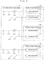
FIG. 6 is a block diagram schematically showing a hot wind supply mechanism equipped in the drying apparatus. An upper-stage drying unit Du including the air-blow dryers stage conveying part 51u, a middle-stage drying unit Dm including the air-blow dryers stage conveying part 51m, and a lower-stage drying unit D1 including the air-blow dryers stage conveying part 511 are shown inFIG. 6 . - The hot wind supply mechanism 9 includes an upper-
stage supplying unit 91u supplying the hot wind to the upper-stage drying unit Du, a middle-stage supplying unit 91m supplying the hot wind to the middle-stage drying unit Dm and a lower-stage supplying unit 911 supplying the hot wind to the lower-stage drying unit Dl. Since the upper-stage supplying unit 91u, the middle-stage supplying unit 91m and the lower-stage supplying unit 911 have a common configuration, this common configuration is described for the upper-stage supplying unit 91u. - The upper-
stage supplying unit 91u includes aninput part 911 to which the air heated by the external heater, i.e. the hot wind is input, anintroduction pipe 912 which introduces the hot wind input from theinput part 911, and abranched pipe 913 branched from theintroduction pipe 912 to the respective air-blow dryers input part 911 is supplied to the respective air-blow dryers branched pipe 913 after passing through theintroduction pipe 912, and injected from thenozzles 76u of the respective air-blow dryers blower 914 which blows the hot wind from the side of theinput part 911 to the side of the upper-stage drying unit Du is mounted in theintroduction pipe 912, and a wind velocity (m/s) of the hot wind to be supplied to the respective air-blow dryers blower 914, with the result that the wind velocity of the hot wind to be injected from thenozzles 76u can be adjusted. - Similarly, for the middle-stage drying unit Dm, the hot wind having the wind velocity thereof adjusted by a
blower 914 is supplied to the air-blow dryers stage supplying unit 91m, and injected from thenozzles blow dryers blower 914 is supplied to the air-blow dryers stage supplying unit 911, and injected from thenozzles blow dryers - Further, the rotation speeds of the
blowers 914 of the upper-stage supplying unit 91u, the middle-stage supplying unit 91m and the lower-stage supplying unit 911 are adjusted in advance, for example, by an operator, and the wind velocity of the air injected from eachnozzle 76u provided in the upper-stage drying unit Du is lower than that of the air injected from eachnozzle nozzle blower 914. That is, a damper may be provided between theblower 914 and thebranched pipe 913 and the wind velocity of the hot wind may be adjusted by changing an opening of the damper. - Further, in this example, the plurality of
nozzles 76u of the air-blow dryers stage conveying part 51u from the plurality ofnozzles 76u. - Furthermore, the plurality of
nozzles 761 of the air-blow dryers stage conveying part 51m from the plurality ofnozzles 761. - Similarly, the plurality of
nozzles 76u of the air-blow dryers stage conveying part 51m from the plurality ofnozzles 76u. - Particularly, in the air-
blow dryers nozzles 761 and that of the air injected by the plurality ofnozzles 76u are equal. Accordingly, it can be suppressed that the printing medium M conveyed by the middle-stage conveying part 51m is shifted to contact either thenozzles 761 or thenozzles 76u. - Further, the wind velocity of the air injected by the
nozzles 76u of the air-blow dryers nozzles 761 of the air-blow dryers stage conveying part 51m and the front surface M1 of the printing medium M conveyed by the lower-stage conveying part 511. - Incidentally, in this specification, the hot wind is a wind of 60°C or higher and the temperature of the hot wind is preferably 80° or higher. Further, the type of a gas injected from the
nozzles - In the embodiment described above, the air-
blow dryers blow dryers unit 51, whereby the printing medium M having the front surface M1 on which the aqueous inks is dried. At this time, the wind velocity of the air injected by the air-blow dryers blow dryers blow dryers blow dryers blow dryers - Further, the air-
blow dryers nozzles 76u (first nozzles) arrayed in the moving direction of the printing medium M conveyed by the conveyingunit 51 on the side of the front surface M1 of the printing medium M, and the air is injected toward the front surface M1 of the printing medium M from thenozzles 76u. Further, the air-blow dryers unit 51 on the side of the front surface M1 of the printing medium M, and the air is injected toward the front surface M1 of the printing medium M from thenozzles 761. At this time, the wind velocity of the air injected by thenozzles 76u of the air-blow dryers nozzles 761 of the air-blow dryers - Further, the plurality of
nozzles 76u of the air-blow dryers nozzles 761 of the air-blow dryers blow dryers nozzles 76u and a uniform wind can be injected to the front surface M1 of the printing medium M passing through the air-blow dryers nozzles 761. - Further, the air-
blow dryers unit 51 on the side of the back surface M2 of the printing medium M. Theserollers 74 have the peripheral surfaces configured to contact the back surface M2 of the printing medium M and rotate, following the printing medium M. That is, in the drying in the air-blow dryers rollers 74 in the air-blow dryers rollers 74 in this way, the formation of creases of the printing medium M can be suppressed against the influence of the temperature distribution caused by the latent heat of the moisture on the printing medium M. - Further, in the air-
blow dryers nozzles 76u and therollers 74 are arranged in a staggered manner in the moving direction of the printing medium M conveyed by the conveyingunit 51. In such a configuration, moisture evaporation from the front surface M1 of the printing medium M can be promoted by air injection from thenozzles 76u, and the formation of creases can be more reliably suppressed by firmly supporting the back surface M2 of the printing medium M byrollers 74. - Further, the air-
blow dryers nozzles 76u (third nozzles) arrayed in the moving direction of the printing medium M conveyed by the conveyingunit 51 on the side of the back surface M2 of the printing medium M, and the air is injected toward the back surface M2 of the printing medium M from thenozzles 76u. At this time, the wind velocity of the air injected by thenozzles 76u of the air-blow dryers nozzles 76u of the air-blow dryers nozzles 76u of the air-blow dryers nozzles 76u of the air-blow dryers blow dryers - Further, the plurality of
nozzles 76u of the air-blow dryers blow dryers nozzles 76u. - Further, the wind velocity of the air injected by the plurality of
nozzles 761 and that of the air injected by the plurality ofnozzles 76u are equal in the air-blow dryers blow dryers nozzles 761 or thenozzles 76u. - Further, in the air-
blow dryers nozzles 761 and thenozzles 76u are arranged in a staggered manner in the moving direction of the printing medium M conveyed by the conveyingunit 51. In such air-blow dryers nozzles 761 and thenozzles 76u are displaced from each other in the moving direction of the printing medium M. Thus, it can be suppressed that the front surface M1 of the printing medium M deflected by the air injected from thenozzles 76u contacts thenozzles 761. - Further, in the vertical direction Z, the air-
blow dryers blow dryers blow dryers blow dryers apparatus 5 can be reduced in size in the horizontal direction X. - Further, the moving direction of the printing medium M conveyed by the conveying
unit 51 in the air-blow dryers unit 51 in the air-blow dryers unit 51 includes therollers 52, 53 (preceding-stage inverter) which bend the printing medium M conveyed from the air-blow dryers blow dryers blow dryers blow dryers rollers - Further, the conveying
unit 51 conveys the printing medium M in the air-blow dryers nozzles 76u are arranged above the printing medium M conveyed by the conveyingunit 51 and therollers 74 are arranged below the printing medium M conveyed by the conveyingunit 51 in the air-blow dryers blow dryers nozzles 76u can be prevented from falling down. - Further, the air-
blow dryers unit 51 is equipped on a downstream side of the air-blow dryers unit 51. In the vertical direction Z, the air-blow dryers blow dryers nozzles 76u (fourth nozzles) arrayed in the moving direction of the printing medium M conveyed by the conveyingunit 51 on the side of the front surface M1 of the printing medium M and inject the air toward the front surface M1 of the printing medium M from thenozzles 76u. At this time, the wind velocity of the air injected by thenozzles 76u of the air-blow dryers nozzles 76u of the air-blow dryers nozzles 76u of the air-blow dryers nozzles 76u of the air-blow dryers blow dryers blow dryers blow dryers blow dryers blow dryers blow dryers apparatus 5 can be reduced in size in the horizontal direction X. - Further, the wind velocity of the air injected by the
nozzles 76u of the air-blow dryers nozzles 761 of the air-blow dryers blow dryers blow dryers - Further, the air-
blow dryers unit 51 on the side of the back surface M2 of the printing medium M and inject the air toward the back surface M2 of the printing medium M from thenozzles 761. At this time, the wind velocity of the air injected by thenozzles 76u of the air-blow dryers nozzles 761 of the air-blow dryers nozzles 761 of the air-blow dryers nozzles 76u of the air-blow dryers blow dryers - Further, the moving direction of the printing medium M conveyed by the conveying
unit 51 in the air-blow dryers unit 51 in the air-blow dryers unit 51 includes the air turn bars 54, 55 (next-stage inverter) which bend the printing medium M conveyed from the air-blow dryers blow dryers blow dryers blow dryers - Further, the air has a temperature of 60°C or higher. In such a configuration, the drying of the printing medium M can be promoted by the hot wind of 60°C or higher.
- Further, the
coating apparatus 2 is provided which applies the primer to the front surface M1 of the printing medium M, and theprinting apparatus 3 adheres the aqueous inks to the front surface M1 on which the primer had been applied by thecoating apparatus 2. In such a configuration, the aqueous inks can be fixed to the front surface M1 of the printing medium M by the primer. - In the embodiment described above, the printing system 1 corresponds to an example of a "printing system" of the invention, the printing apparatus 3 corresponds to an example of a "printing apparatus" of the invention, the drying apparatus 5 corresponds to an example of a "drying apparatus" of the invention, the conveying unit 51 corresponds to an example of a "conveyor" of the invention, the rollers 52, 53 correspond to an example of a "preceding-stage inverter" of the invention, the air-blow dryers 7a, 7b correspond to an example of a "preceding-stage dryer" of the invention, the air-blow dryers 7c, 7d correspond to an example of a "next-stage dryer" of the invention, the air-blow dryers 7e, 7f correspond to an example of a "succeeding-stage dryer" of the invention, the nozzles 76u of the air-blow dryers 7a, 7b correspond to an example of "first nozzles" of the invention, the nozzles 761 of the air-blow dryers 7c, 7d correspond to an example of "second nozzles" of the invention, the nozzles 76u of the air-blow dryers 7c, 7d correspond to an example of "third nozzles" of the invention, the nozzles 76u of the air-blow dryers 7e, 7f correspond to an example of "fourth nozzles" of the invention, the nozzles 761 of the air-blow dryers 7e, 7f correspond to an example of "fifth nozzles" of the invention, the rollers 74 correspond to an example of "rotary bodies" of the invention, the printing medium M corresponds to an example of a "printing medium" of the invention, the front surface M1 corresponds to an example of a "recording surface" of the invention, the back surface M2 corresponds to an example of a "non-recording surface" of the invention, a "conveying step" of the invention is performed by the conveying unit 51, a "preceding-stage drying step" of the invention is performed by the air-blow dryers 7a, 7b and a "next-stage drying step" of the invention is performed by the air-blow dryers 7c, 7d.
- Note that the invention is not limited to the above embodiment and various changes other than the aforementioned ones can be made without departing from the gist of the invention. That is, in the above example, the plurality of
nozzles 76u of the air-blow dryers nozzles 761 of the air-blow dryers respective nozzles 76u of the air-blow dryers nozzles 76u. Similarly, the wind velocity may be different among therespective nozzles 761 of the air-blow dryers respective nozzles 76u of the air-blow dryers respective nozzles 761 of the air-blow dryers - Further, the wind velocity of the air injected from the
nozzles 76u of the air-blow dryers nozzles 761 of the air-blow dryers blow dryers blow dryers nozzles 76u of the air-blow dryer 7a may be set to be lower than those of the air injected from thenozzles blow dryers blow dryer 7a corresponds to the "preceding-stage dryer" of the invention, and the air-blow dryers - Further, in the air-
blow dryer nozzles 76u and that of therollers 74 need not be equal, and the number of thenozzles 76u may be more than or less than that of therollers 74. - Alternatively, as shown in
FIG. 7 , somerollers 74 may be replaced bynozzles 761. Here,FIG 7 is a front view schematically showing a modification of the drying apparatus. A dryingapparatus 5 ofFIG. 7 differs from the dryingapparatus 5 ofFIG. 3 in that an air-blow dryer 7a includes thenozzles 761 below the printing medium M, and the other configuration is common in these dryingapparatuses 5. - The air-
blow dryer 7a of thedrying apparatus 5 shown inFIG. 7 includes a plurality of (less than the number ofnozzles 76u by N)rollers 74 andN nozzles 761 arranged below the printing medium M. Note that N is an integer of 1 or greater, and "4" in this example. The plurality ofrollers 74 are arrayed at a predetermined interval in the moving direction (horizontal direction X) of the printing medium M conveyed by the upper-stage conveying part 51u, and the peripheral surface of eachroller 74 contacts the back surface M2 (lower surface) of the printing medium M conveyed by the upper-stage conveying part 51u from below. Further, theN nozzles 761 are arrayed at a predetermined interval in the horizontal direction X and inject a hot wind to the back surface M2 of the printing medium M from below. In the moving direction of the printing medium M conveyed by the upper-stage conveying part 51u, the plurality of theserollers 74 are located downstream of theN nozzles 761, and the printing medium M conveyed by the upper-stage conveying part 51u is supported from below by therollers 74 after the hot wind is injected from thenozzles 761. - As just described, in the example of
FIG 7 , the air-blow dryers nozzles 761 arranged upstream of the most upstream roller 74 (roller 74 at a right end ofFIG. 7 ), out of the plurality of rollers 74 (rotary bodies), in the moving direction of the printing medium M conveyed by the upper-stage conveying part 51u on the side of the back surface M2 (non-recording surface) of the printing medium M, and thenozzles 761 inject the hot wind to the back surface M2. In an initial stage in which the printing medium M enters the air-blow dryers port 61, a temperature distribution in the printing medium M is relatively uniform. Thus, the drying of the printing medium M can be promoted by injecting the hot wind to the back surface M2 of the printing medium M from thenozzles 761. -
FIG. 8 is a diagram schematically showing another modification of the drying apparatus. In this modification, adrying apparatus 5 includesheating unit 75 heating a plurality ofrollers 74. Theheating unit 75 includes aheating wire 751 arranged inside theroller 74 and apower supply 752 supplying a current to theheating wire 751. Theheating wire 751 is provided in each of the plurality ofrollers 74. Theheating wire 751 generates heat by the current supplied from thepower supply 752 and heats theroller 74. Accordingly, the printing medium M conveyed by the upper-stage conveying part 51u is supported from below by theheated rollers 74. In such a configuration, the drying of the printing medium M can be promoted by the heat of therollers 74. - Further, modifications different from those of
FIGS. 7 and8 can also be added. For example, the air-blow dryer 7b may have the same configuration as the air-blow dryer 7e. In such a modification, the air-blow dryer 7b does not include therollers 74 and supports the printing medium M bynozzles 76u andnozzles 761 arranged above and below the printing medium M, and only the air-blow dryer 7a includes therollers 74. - Further, it is not always necessary to arrange two air-blow dryers for each of the upper-
stage conveying part 51u, the middle-stage conveying part 51m and the lower-stage conveying part 511. Accordingly, a single air-blow dryer 7a may be arranged for the upper-stage conveying part 51u, a single air-blow dryer 7d may be arranged for the middle-stage conveying part 51m and a single air-blow dryer 7e may be arranged for the lower-stage conveying part 511. - Further, the air-
blow dryers 7a to 7f need not necessarily be arranged separately in the vertical direction. Accordingly, the air-blow dryers 7a to 7d may be arranged at the same height and arrayed in the horizontal direction X. Alternatively, the air-blow dryers 7a to 7f may be arranged at the same height and arrayed in the horizontal direction X. - Further, the upper-
stage supplying unit 91u, the middle-stage supplying unit 91m and the lower-stage supplying unit 911 need not have the same configuration. Accordingly, a feedback pipe to return the air exhausted from theexhaust chambers introduction pipe 912 of the middle-stage supplying unit 91m may be, for example, provided. Further, a similar feedback pipe may be provided in the lower-stage supplying unit 911 to return the air exhausted from theexhaust chambers - Further, the specific configuration of the conveying
unit 4 is not limited to the above example. Accordingly, the arrangement or number of the rollers can be changed as appropriate in the carry-inpart 41, theascending conveying part 42, the upper conveyingpart 43, thedescending conveying part 44, thecolor conveying part 45, theinverting conveying part 47, the white conveyingpart 48 and the carry-outpart 49. - Further, the printing medium M needs not be carried into the
housing 31 of theprinting apparatus 3 through the carry-inpart 41. For example, theprinting apparatus 3 may be so configured as to carry the printing medium M into the upper conveyingpart 43 from the one side X1 of thehousing 31 without providing the carry-inpart 41 and theascending conveying part 42. - Further, it is not essential to provide the pre-dryer 34 and the
upper dryer 35 in theprinting apparatus 3. - As described above, the drying apparatus may be configured so that the preceding-stage dryer includes a plurality of first nozzles arrayed in the moving direction of the printing medium conveyed by the conveyor on the recording surface side of the printing medium and injects the gas toward the recording surface of the printing medium from the first nozzles, the next-stage dryer includes a plurality of second nozzles arrayed in the moving direction of the printing medium conveyed by the conveyor on the recording surface side of the printing medium and injects the gas toward the recording surface of the printing medium from the second nozzles, and a wind velocity of the gas injected by the first nozzle is lower than a wind velocity of the gas injected by the second nozzle. In this way, a time required to dry the printing medium can be suppressed while a disturbance of an image due to the flow of the aqueous ink caused by the injected gas is suppressed.
- The drying apparatus may be configured so that the plurality of first nozzles inject the gas at the same wind velocity, and the plurality of second nozzles inject the gas at the same wind velocity. In such a configuration, a uniform wind can be injected to the printing medium passing through the preceding-stage dryer from the first nozzles and a uniform wind can be injected to the printing medium passing through the next-stage dryer from the second nozzles.
- The drying apparatus may be configured so that the preceding-stage dryer includes a plurality of rotary bodies arrayed in the moving direction of the printing medium conveyed by the conveyor on the non-recording surface side of the printing medium, and the rotary bodies have peripheral surfaces contacting the non-recording surface of the printing medium and rotate, following the printing medium. That is, in the drying in the preceding-stage dryer, a temperature distribution of the printing medium becomes nonuniform due to the latent heat of a large amount of moisture remaining on the printing medium and the printing medium is easily creased. As a countermeasure against this, the non-recording surface of the printing medium is supported by the rotary bodies in the preceding-stage dryer. In this way, the printing medium is extended along the rotary bodies, whereby the formation of creases of the printing medium can be suppressed against the influence of the temperature distribution due to the latent heat of the moisture on the printing medium.
- The drying apparatus may be configured so that the first nozzles and the rotary bodies are arranged in a staggered manner in the moving direction of the printing medium conveyed by the conveyor in the preceding-stage dryer. In such a configuration, moisture evaporation from the recording surface of the printing medium can be promoted by the injection of the gas from the first nozzles, and the formation of creases can be more reliably suppressed by firmly supporting the non-recording surface of the printing medium by the rotary bodies.
- The drying apparatus may be configures so that the next-stage dryer includes a plurality of third nozzles arrayed in the moving direction of the printing medium conveyed by the conveyor on the non-recording surface side of the printing medium and injects the gas toward the non-recording surface of the printing medium from the third nozzles, and a wind velocity of the gas injected by the first nozzle is lower than a wind velocity of the gas injected by the third nozzle. In such a configuration, the drying of the printing medium can be promoted by injecting the gas at a high wind velocity to the printing medium passing through the next-stage dryer from both sides.
- The drying apparatus may be configured so that the plurality of third nozzles inject the gas at the same wind velocity. In such a configuration, a uniform wind can be injected to the printing medium passing through the next-stage dryer from the plurality of third nozzles.
- The drying apparatus may be configured so that a wind velocity of the gas injected by the plurality of second nozzles is equal to a wind velocity of the gas injected by the plurality of third nozzles. In such a configuration, it can be suppressed that the printing medium passing through the next-stage dryer is shifted to contact either the second nozzles or the third nozzles.
- The drying apparatus may be configured so that the second nozzles and the third nozzles are arranged in a staggered manner in the moving direction of the printing medium conveyed by the conveyor in the next-stage dryer. In such a next-stage dryer, the second nozzles and the third nozzles are displaced from each other in the moving direction of the printing medium. Accordingly, it can be suppressed that the recording surface of the printing medium deflected by the gas injected from the third nozzles contacts the second nozzles.
- The drying apparatus may be configured so that the next-stage dryer is arranged below the preceding-stage dryer in a vertical direction. In such a configuration, the dryer can be reduced in size in the horizontal direction.
- The drying apparatus may be configured so that the moving direction of the printing medium conveyed by the conveyor in the preceding-stage dryer and the moving direction of the printing medium conveyed by the conveyor in the next-stage dryer are opposite, and the conveyor includes a preceding-stage inverter bends the printing medium conveyed from the preceding-stage dryer downward and further bends the printing medium toward the next-stage dryer. In such a configuration, the printing medium can be precisely conveyed from the preceding-stage dryer on an upper side to the next-stage dryer on a lower side by the preceding-stage inverter.
- The drying apparatus may be configured so that the next-stage dryer includes a plurality of third nozzles arrayed in the moving direction of the printing medium conveyed by the conveyor on the non-recording surface side of the printing medium and injects the gas toward the non-recording surface of the printing medium from the third nozzles, a wind velocity of the gas injected by the first nozzle is lower than a wind velocity of the gas injected by the third nozzle, the next-stage dryer is arranged below the preceding-stage dryer in a vertical direction, the moving direction of the printing medium conveyed by the conveyor in the preceding-stage dryer and the moving direction of the printing medium conveyed by the conveyor in the next-stage dryer are opposite, the conveyor conveys the printing medium in the preceding-stage dryer with the recording surface facing up and the non-recording surface facing down and conveys the printing medium in the next-stage dryer with the recording surface facing down and the non-recording surface facing up, the first nozzles are arranged above the printing medium conveyed by the conveyor, the rotary bodies are arranged below the printing medium conveyed by the conveyor, the second nozzles are arranged below the printing medium conveyed by the conveyor, and the third nozzles are arranged above the printing medium conveyed by the conveyor. In such a configuration, since the recording surface is facing up in the preceding-stage dryer in which a large amount of moisture remains on the recording surface, the moisture blown by the gas injected from the first nozzles can be prevented from falling down.
- The drying apparatus may further comprises a succeeding-stage dryer which dries the printing medium by injecting the gas toward the recording surface of the printing medium being conveyed by the conveyor on a side downstream of the next-stage dryer in the moving direction of the printing medium conveyed by the conveyor, wherein: the succeeding-stage dryer is arranged below the next-stage dryer in a vertical direction, the succeeding-stage dryer includes a plurality of fourth nozzles arrayed in the moving direction of the printing medium conveyed by the conveyor on the recording surface side of the printing medium and injects the gas toward the recording surface of the printing medium from the fourth nozzles, and a wind velocity of the gas injected by the first nozzle is lower than a wind velocity of the gas injected by the fourth nozzle. In such a configuration, since the printing medium dried by the next-stage dryer is further dried by the succeeding-stage dryer, the printing medium can be more reliably dried. Moreover, since the succeeding-stage dryer is arranged below the next-stage dryer, the drying apparatus can be reduced in size in the horizontal direction.
- The drying apparatus may be configured so that a wind velocity of the gas injected by the fourth nozzle and a wind velocity of the gas injected by the second nozzle are equal. In such a configuration, the drying of the printing medium can be promoted by injecting the gas at a high wind velocity to the printing medium passing through the next-stage dryer and the succeeding-stage dryer.
- The drying apparatus may be configured so that the succeeding-stage dryer includes a plurality of fifth nozzles arrayed in the moving direction of the printing medium conveyed by the conveyor on the non-recording surface side of the printing medium and injects the gas toward the non-recording surface of the printing medium from the fifth nozzles, and a wind velocity of the gas injected by the first nozzle is lower than a wind velocity of the gas injected by the fifth nozzle. In such a configuration, the drying of the printing medium can be promoted by injecting the gas at a high wind velocity to the printing medium passing through the succeeding-stage dryer from both sides.
- The drying apparatus may be configured so that the moving direction of the printing medium conveyed by the conveyor in the next-stage dryer and the moving direction of the printing medium conveyed by the conveyor in the succeeding-stage dryer are opposite, and the conveyor includes a next-stage inverter which bends the printing medium conveyed from the next-stage dryer downward and further bends the printing medium toward the succeeding-stage dryer. In such a configuration, the printing medium can be precisely conveyed from the next-stage dryer on an upper side to the succeeding-stage dryer on a lower side by the next-stage inverter.
- The drying apparatus according to any one of
claims 1 to 16, wherein the gas has a temperature of 60°C or higher. In such a configuration, the drying of the printing medium can be promoted by a hot wind of 60°C or higher. - The invention is applicable to techniques in general for drying a printing medium M adhered with aqueous ink(s) by a hot wind.
- Although the invention has been described with reference to specific embodiments, this description is not meant to be construed in a limiting sense. Various modifications of the disclosed embodiment, as well as other embodiments of the present invention, will become apparent to persons skilled in the art upon reference to the description of the invention. It is therefore contemplated that the appended claims will cover any such modifications or embodiments as fall within the true scope of the invention.
Claims (20)
- A drying apparatus, comprising:a conveyor which conveys a printing medium having a recording surface and a non-recording surface opposite to the recording surface, an aqueous ink adhering to the recording surface,a preceding-stage dryer which dries the printing medium by injecting a gas toward the recording surface of the printing medium being conveyed by the conveyor; anda next-stage dryer which dries the printing medium by injecting the gas toward the recording surface of the printing medium being conveyed by the conveyor on a side downstream of the preceding-stage dryer in a moving direction of the printing medium conveyed by the conveyor,a wind velocity of the gas injected by the preceding-stage dryer being lower than a wind velocity of the gas injected by the next-stage dryer.
- The drying apparatus according to claim 1, wherein:the preceding-stage dryer includes a plurality of first nozzles arrayed in the moving direction of the printing medium conveyed by the conveyor on the recording surface side of the printing medium and injects the gas toward the recording surface of the printing medium from the first nozzles,the next-stage dryer includes a plurality of second nozzles arrayed in the moving direction of the printing medium conveyed by the conveyor on the recording surface side of the printing medium and injects the gas toward the recording surface of the printing medium from the second nozzles, anda wind velocity of the gas injected by the first nozzle is lower than a wind velocity of the gas injected by the second nozzle.
- The drying apparatus according to claim 2, wherein the plurality of first nozzles inject the gas at the same wind velocity, and the plurality of second nozzles inject the gas at the same wind velocity.
- The drying apparatus according to claim 2 or 3, wherein the preceding-stage dryer includes a plurality of rotary bodies arrayed in the moving direction of the printing medium conveyed by the conveyor on the non-recording surface side of the printing medium, and the rotary bodies have peripheral surfaces contacting the non-recording surface of the printing medium and rotate, following the printing medium.
- The drying apparatus according to claim 4, wherein the first nozzles and the rotary bodies are arranged in a staggered manner in the moving direction of the printing medium conveyed by the conveyor in the preceding-stage dryer.
- The drying apparatus according to any one of claims 2 to 5, wherein:the next-stage dryer includes a plurality of third nozzles arrayed in the moving direction of the printing medium conveyed by the conveyor on the non-recording surface side of the printing medium and injects the gas toward the non-recording surface of the printing medium from the third nozzles, anda wind velocity of the gas injected by the first nozzle is lower than a wind velocity of the gas injected by the third nozzle.
- The drying apparatus according to claim 6, wherein the plurality of third nozzles inject the gas at the same wind velocity.
- The drying apparatus according to claim 6 or 7, wherein a wind velocity of the gas injected by the plurality of second nozzles is equal to a wind velocity of the gas injected by the plurality of third nozzles.
- The drying apparatus according to any one of claims 6 to 8, wherein the second nozzles and the third nozzles are arranged in a staggered manner in the moving direction of the printing medium conveyed by the conveyor in the next-stage dryer.
- The drying apparatus according to any one of claims 2 to 9, wherein the next-stage dryer is arranged below the preceding-stage dryer in a vertical direction.
- The drying apparatus according to claim 10, wherein:the moving direction of the printing medium conveyed by the conveyor in the preceding-stage dryer and the moving direction of the printing medium conveyed by the conveyor in the next-stage dryer are opposite, andthe conveyor includes a preceding-stage inverter bends the printing medium conveyed from the preceding-stage dryer downward and further bends the printing medium toward the next-stage dryer.
- The drying apparatus according to claim 4, wherein:the next-stage dryer includes a plurality of third nozzles arrayed in the moving direction of the printing medium conveyed by the conveyor on the non-recording surface side of the printing medium and injects the gas toward the non-recording surface of the printing medium from the third nozzles,a wind velocity of the gas injected by the first nozzle is lower than a wind velocity of the gas injected by the third nozzle,the next-stage dryer is arranged below the preceding-stage dryer in a vertical direction,the moving direction of the printing medium conveyed by the conveyor in the preceding-stage dryer and the moving direction of the printing medium conveyed by the conveyor in the next-stage dryer are opposite,the conveyor conveys the printing medium in the preceding-stage dryer with the recording surface facing up and the non-recording surface facing down and conveys the printing medium in the next-stage dryer with the recording surface facing down and the non-recording surface facing up,the first nozzles are arranged above the printing medium conveyed by the conveyor,the rotary bodies are arranged below the printing medium conveyed by the conveyor,the second nozzles are arranged below the printing medium conveyed by the conveyor, andthe third nozzles are arranged above the printing medium conveyed by the conveyor.
- The drying apparatus according to any one of claims 2 to 12, further comprising a succeeding-stage dryer which dries the printing medium by injecting the gas toward the recording surface of the printing medium being conveyed by the conveyor on a side downstream of the next-stage dryer in the moving direction of the printing medium conveyed by the conveyor, wherein:the succeeding-stage dryer is arranged below the next-stage dryer in a vertical direction,the succeeding-stage dryer includes a plurality of fourth nozzles arrayed in the moving direction of the printing medium conveyed by the conveyor on the recording surface side of the printing medium and injects the gas toward the recording surface of the printing medium from the fourth nozzles, anda wind velocity of the gas injected by the first nozzle is lower than a wind velocity of the gas injected by the fourth nozzle.
- The drying apparatus according to claim 13, wherein a wind velocity of the gas injected by the fourth nozzle and a wind velocity of the gas injected by the second nozzle are equal.
- The drying apparatus according to claim 13 or 14, wherein:the succeeding-stage dryer includes a plurality of fifth nozzles arrayed in the moving direction of the printing medium conveyed by the conveyor on the non-recording surface side of the printing medium and injects the gas toward the non-recording surface of the printing medium from the fifth nozzles, anda wind velocity of the gas injected by the first nozzle is lower than a wind velocity of the gas injected by the fifth nozzle.
- The drying apparatus according to any one of claims 13 to 15, wherein:the moving direction of the printing medium conveyed by the conveyor in the next-stage dryer and the moving direction of the printing medium conveyed by the conveyor in the succeeding-stage dryer are opposite, andthe conveyor includes a next-stage inverter which bends the printing medium conveyed from the next-stage dryer downward and further bends the printing medium toward the succeeding-stage dryer.
- The drying apparatus according to any one of claims 1 to 16, wherein the gas has a temperature of 60°C or higher.
- A printing system, comprising:a printing apparatus which adheres an aqueous ink to a recording surface of a printing medium having the recording surface and a non-recording surface opposite to the recording surface; andthe drying apparatus according to any one of claims 1 to 17,the drying apparatus drying the printing medium having the aqueous ink adhered thereto by the printing apparatus.
- The printing system according to claim 18, further comprising a coating apparatus which applies a primer to the recording surface of the printing medium, wherein:
the printing apparatus adheres the aqueous ink to the recording surface having the primer applied thereto by the coating apparatus. - A drying method, comprising:a conveying step of conveying a printing medium having a recording surface and a non-recording surface opposite to the recording surface and having an aqueous ink adhered to the recording surface by a conveyor;a preceding-stage drying step of drying the printing medium by injecting a gas toward the recording surface of the printing medium being conveyed by the conveyor by a preceding-stage dryer; anda next-stage drying step of drying the printing medium by injecting the gas toward the recording surface of the printing medium being conveyed by the conveyor by a next-stage dryer on a side downstream of the preceding-stage dryer in a moving direction of the printing medium conveyed by the conveyor,a wind velocity of the gas injected by the preceding-stage dryer being lower than a wind velocity of the gas injected by the next-stage dryer.
Applications Claiming Priority (1)
| Application Number | Priority Date | Filing Date | Title |
|---|---|---|---|
| JP2020050485A JP7446680B2 (en) | 2020-03-23 | 2020-03-23 | Drying equipment, printing system and drying method |
Publications (2)
| Publication Number | Publication Date |
|---|---|
| EP3885148A1 true EP3885148A1 (en) | 2021-09-29 |
| EP3885148B1 EP3885148B1 (en) | 2024-05-08 |
Family
ID=74853528
Family Applications (1)
| Application Number | Title | Priority Date | Filing Date |
|---|---|---|---|
| EP21159989.9A Active EP3885148B1 (en) | 2020-03-23 | 2021-03-01 | Drying apparatus, printing system and drying method |
Country Status (4)
| Country | Link |
|---|---|
| US (1) | US11590774B2 (en) |
| EP (1) | EP3885148B1 (en) |
| JP (1) | JP7446680B2 (en) |
| KR (1) | KR102572396B1 (en) |
Families Citing this family (4)
| Publication number | Priority date | Publication date | Assignee | Title |
|---|---|---|---|---|
| JP7430084B2 (en) * | 2020-03-23 | 2024-02-09 | 株式会社Screenホールディングス | Printing device, printing system and printing method |
| EP4389434A1 (en) * | 2022-12-20 | 2024-06-26 | Bobst Italia S.P.A. | Inkjet printing machine with nozzle drier |
| JP2024173376A (en) * | 2023-06-02 | 2024-12-12 | キヤノン株式会社 | Recording apparatus and method for drying a recording apparatus |
| IT202400006259A1 (en) * | 2024-03-20 | 2025-09-20 | Expert S R L | APPARATUS FOR DRYING A PRINTED RIBBON |
Citations (3)
| Publication number | Priority date | Publication date | Assignee | Title |
|---|---|---|---|---|
| JP2000024574A (en) | 1998-07-07 | 2000-01-25 | Tdk Corp | Floating nozzle and floating method |
| US20190184717A1 (en) * | 2017-12-19 | 2019-06-20 | Seiko Epson Corporation | Heating device and medium processing apparatus |
| US20190283459A1 (en) * | 2018-03-16 | 2019-09-19 | Ricoh Company, Ltd. | Dryer, liquid discharge apparatus, drying method, and inkjet recording apparatus |
Family Cites Families (19)
| Publication number | Priority date | Publication date | Assignee | Title |
|---|---|---|---|---|
| JP2000329463A (en) | 1999-05-14 | 2000-11-30 | Konica Corp | Method and equipment for drying coat |
| JP2002331267A (en) | 2001-05-09 | 2002-11-19 | Fuji Photo Film Co Ltd | Method for drying coating film |
| JP2004358779A (en) | 2003-06-04 | 2004-12-24 | Toshiba Mach Co Ltd | Drying apparatus for printing machine |
| JP2005178235A (en) | 2003-12-22 | 2005-07-07 | Toppan Printing Co Ltd | Gravure drying equipment |
| JP2010222090A (en) | 2009-03-23 | 2010-10-07 | Lintec Corp | Heating furnace and conveying roller |
| JP2012107792A (en) | 2010-11-16 | 2012-06-07 | Panasonic Corp | Device for drying coating liquid on web |
| JP5587158B2 (en) | 2010-12-16 | 2014-09-10 | 株式会社オリエント総業 | Nozzle and drying device |
| JP2012149788A (en) * | 2011-01-17 | 2012-08-09 | Clean Technology Kk | Film coating machine |
| JP5776508B2 (en) | 2011-11-22 | 2015-09-09 | トヨタ自動車株式会社 | Electrode sheet drying device |
| JP2016525950A (en) | 2013-04-24 | 2016-09-01 | オセ−テクノロジーズ ビーブイ | Printing method |
| JP6168596B2 (en) | 2013-06-06 | 2017-07-26 | 大阪シーリング印刷株式会社 | Drying device and printing device |
| JP6283540B2 (en) | 2014-03-12 | 2018-02-21 | 株式会社Screenホールディングス | Drying apparatus and processing film forming system |
| WO2017069074A1 (en) | 2015-10-19 | 2017-04-27 | コニカミノルタ株式会社 | Recording method, drying method, recording system, and drying device |
| JP6844194B2 (en) | 2015-12-02 | 2021-03-17 | 株式会社リコー | Drying equipment, transfer system |
| WO2019131843A1 (en) * | 2017-12-28 | 2019-07-04 | 株式会社Screenホールディングス | Printing device |
| JP2019119609A (en) | 2017-12-28 | 2019-07-22 | 株式会社Screenホールディングス | Printing machine |
| JP2019162870A (en) * | 2018-03-16 | 2019-09-26 | 株式会社リコー | Dryer, liquid discharge device, drying method, and ink jet recording device |
| JP7387504B2 (en) | 2020-03-23 | 2023-11-28 | 株式会社Screenホールディングス | Drying equipment, printing system and drying method |
| JP7430084B2 (en) | 2020-03-23 | 2024-02-09 | 株式会社Screenホールディングス | Printing device, printing system and printing method |
-
2020
- 2020-03-23 JP JP2020050485A patent/JP7446680B2/en active Active
-
2021
- 2021-01-11 KR KR1020210003592A patent/KR102572396B1/en active Active
- 2021-03-01 EP EP21159989.9A patent/EP3885148B1/en active Active
- 2021-03-04 US US17/192,377 patent/US11590774B2/en active Active
Patent Citations (3)
| Publication number | Priority date | Publication date | Assignee | Title |
|---|---|---|---|---|
| JP2000024574A (en) | 1998-07-07 | 2000-01-25 | Tdk Corp | Floating nozzle and floating method |
| US20190184717A1 (en) * | 2017-12-19 | 2019-06-20 | Seiko Epson Corporation | Heating device and medium processing apparatus |
| US20190283459A1 (en) * | 2018-03-16 | 2019-09-19 | Ricoh Company, Ltd. | Dryer, liquid discharge apparatus, drying method, and inkjet recording apparatus |
Also Published As
| Publication number | Publication date |
|---|---|
| EP3885148B1 (en) | 2024-05-08 |
| US20210291562A1 (en) | 2021-09-23 |
| KR20210118730A (en) | 2021-10-01 |
| KR102572396B1 (en) | 2023-08-29 |
| US11590774B2 (en) | 2023-02-28 |
| JP7446680B2 (en) | 2024-03-11 |
| JP2021148378A (en) | 2021-09-27 |
Similar Documents
| Publication | Publication Date | Title |
|---|---|---|
| EP3885148B1 (en) | Drying apparatus, printing system and drying method | |
| EP3885149B1 (en) | Drying apparatus, printing system and drying method | |
| EP3885150B1 (en) | Printing apparatus, printing system and printing method | |
| US8622538B2 (en) | Recording apparatus and recording method | |
| US8628188B2 (en) | Drying apparatus and printing apparatus | |
| US11320201B2 (en) | Web drying apparatus and web drying method | |
| EP3970979B1 (en) | Printing apparatus and printing method | |
| JP7636198B2 (en) | Drying device, printing system and drying method | |
| JP2023116266A (en) | Substrate drying device and printing device | |
| JP2025116289A (en) | Drying device, printing system and drying method | |
| US20220396085A1 (en) | Condensation control in an inkjet printer | |
| JP7453108B2 (en) | Drying equipment and drying method | |
| JP2025165444A (en) | Drying device and drying method | |
| JP2007331239A (en) | Liquid droplet discharger | |
| JP2023139840A (en) | Drying device, method for preventing print media from falling off, and method for adjusting position of non-contact support member | |
| JP2022125856A (en) | Droplet discharge device and image formation device | |
| JP2021067395A (en) | Recording medium drier and ink jet recording device |
Legal Events
| Date | Code | Title | Description |
|---|---|---|---|
| PUAI | Public reference made under article 153(3) epc to a published international application that has entered the european phase |
Free format text: ORIGINAL CODE: 0009012 |
|
| STAA | Information on the status of an ep patent application or granted ep patent |
Free format text: STATUS: THE APPLICATION HAS BEEN PUBLISHED |
|
| AK | Designated contracting states |
Kind code of ref document: A1 Designated state(s): AL AT BE BG CH CY CZ DE DK EE ES FI FR GB GR HR HU IE IS IT LI LT LU LV MC MK MT NL NO PL PT RO RS SE SI SK SM TR |
|
| STAA | Information on the status of an ep patent application or granted ep patent |
Free format text: STATUS: REQUEST FOR EXAMINATION WAS MADE |
|
| 17P | Request for examination filed |
Effective date: 20220328 |
|
| RBV | Designated contracting states (corrected) |
Designated state(s): AL AT BE BG CH CY CZ DE DK EE ES FI FR GB GR HR HU IE IS IT LI LT LU LV MC MK MT NL NO PL PT RO RS SE SI SK SM TR |
|
| STAA | Information on the status of an ep patent application or granted ep patent |
Free format text: STATUS: EXAMINATION IS IN PROGRESS |
|
| 17Q | First examination report despatched |
Effective date: 20230123 |
|
| GRAP | Despatch of communication of intention to grant a patent |
Free format text: ORIGINAL CODE: EPIDOSNIGR1 |
|
| STAA | Information on the status of an ep patent application or granted ep patent |
Free format text: STATUS: GRANT OF PATENT IS INTENDED |
|
| INTG | Intention to grant announced |
Effective date: 20231009 |
|
| GRAS | Grant fee paid |
Free format text: ORIGINAL CODE: EPIDOSNIGR3 |
|
| P01 | Opt-out of the competence of the unified patent court (upc) registered |
Effective date: 20240119 |
|
| GRAA | (expected) grant |
Free format text: ORIGINAL CODE: 0009210 |
|
| STAA | Information on the status of an ep patent application or granted ep patent |
Free format text: STATUS: THE PATENT HAS BEEN GRANTED |
|
| AK | Designated contracting states |
Kind code of ref document: B1 Designated state(s): AL AT BE BG CH CY CZ DE DK EE ES FI FR GB GR HR HU IE IS IT LI LT LU LV MC MK MT NL NO PL PT RO RS SE SI SK SM TR |
|
| REG | Reference to a national code |
Ref country code: GB Ref legal event code: FG4D |
|
| REG | Reference to a national code |
Ref country code: CH Ref legal event code: EP |
|
| REG | Reference to a national code |
Ref country code: DE Ref legal event code: R096 Ref document number: 602021012916 Country of ref document: DE |
|
| REG | Reference to a national code |
Ref country code: IE Ref legal event code: FG4D |
|
| REG | Reference to a national code |
Ref country code: LT Ref legal event code: MG9D |
|
| REG | Reference to a national code |
Ref country code: NL Ref legal event code: MP Effective date: 20240508 |
|
| PG25 | Lapsed in a contracting state [announced via postgrant information from national office to epo] |
Ref country code: IS Free format text: LAPSE BECAUSE OF FAILURE TO SUBMIT A TRANSLATION OF THE DESCRIPTION OR TO PAY THE FEE WITHIN THE PRESCRIBED TIME-LIMIT Effective date: 20240908 |
|
| PG25 | Lapsed in a contracting state [announced via postgrant information from national office to epo] |
Ref country code: BG Free format text: LAPSE BECAUSE OF FAILURE TO SUBMIT A TRANSLATION OF THE DESCRIPTION OR TO PAY THE FEE WITHIN THE PRESCRIBED TIME-LIMIT Effective date: 20240508 |
|
| PG25 | Lapsed in a contracting state [announced via postgrant information from national office to epo] |
Ref country code: HR Free format text: LAPSE BECAUSE OF FAILURE TO SUBMIT A TRANSLATION OF THE DESCRIPTION OR TO PAY THE FEE WITHIN THE PRESCRIBED TIME-LIMIT Effective date: 20240508 Ref country code: FI Free format text: LAPSE BECAUSE OF FAILURE TO SUBMIT A TRANSLATION OF THE DESCRIPTION OR TO PAY THE FEE WITHIN THE PRESCRIBED TIME-LIMIT Effective date: 20240508 |
|
| PG25 | Lapsed in a contracting state [announced via postgrant information from national office to epo] |
Ref country code: GR Free format text: LAPSE BECAUSE OF FAILURE TO SUBMIT A TRANSLATION OF THE DESCRIPTION OR TO PAY THE FEE WITHIN THE PRESCRIBED TIME-LIMIT Effective date: 20240809 |
|
| PG25 | Lapsed in a contracting state [announced via postgrant information from national office to epo] |
Ref country code: PT Free format text: LAPSE BECAUSE OF FAILURE TO SUBMIT A TRANSLATION OF THE DESCRIPTION OR TO PAY THE FEE WITHIN THE PRESCRIBED TIME-LIMIT Effective date: 20240909 |
|
| REG | Reference to a national code |
Ref country code: AT Ref legal event code: MK05 Ref document number: 1684698 Country of ref document: AT Kind code of ref document: T Effective date: 20240508 |
|
| PG25 | Lapsed in a contracting state [announced via postgrant information from national office to epo] |
Ref country code: NL Free format text: LAPSE BECAUSE OF FAILURE TO SUBMIT A TRANSLATION OF THE DESCRIPTION OR TO PAY THE FEE WITHIN THE PRESCRIBED TIME-LIMIT Effective date: 20240508 |
|
| PG25 | Lapsed in a contracting state [announced via postgrant information from national office to epo] |
Ref country code: ES Free format text: LAPSE BECAUSE OF FAILURE TO SUBMIT A TRANSLATION OF THE DESCRIPTION OR TO PAY THE FEE WITHIN THE PRESCRIBED TIME-LIMIT Effective date: 20240508 |
|
| PG25 | Lapsed in a contracting state [announced via postgrant information from national office to epo] |
Ref country code: AT Free format text: LAPSE BECAUSE OF FAILURE TO SUBMIT A TRANSLATION OF THE DESCRIPTION OR TO PAY THE FEE WITHIN THE PRESCRIBED TIME-LIMIT Effective date: 20240508 |
|
| PG25 | Lapsed in a contracting state [announced via postgrant information from national office to epo] |
Ref country code: PL Free format text: LAPSE BECAUSE OF FAILURE TO SUBMIT A TRANSLATION OF THE DESCRIPTION OR TO PAY THE FEE WITHIN THE PRESCRIBED TIME-LIMIT Effective date: 20240508 |
|
| PG25 | Lapsed in a contracting state [announced via postgrant information from national office to epo] |
Ref country code: LV Free format text: LAPSE BECAUSE OF FAILURE TO SUBMIT A TRANSLATION OF THE DESCRIPTION OR TO PAY THE FEE WITHIN THE PRESCRIBED TIME-LIMIT Effective date: 20240508 |
|
| PG25 | Lapsed in a contracting state [announced via postgrant information from national office to epo] |
Ref country code: PT Free format text: LAPSE BECAUSE OF FAILURE TO SUBMIT A TRANSLATION OF THE DESCRIPTION OR TO PAY THE FEE WITHIN THE PRESCRIBED TIME-LIMIT Effective date: 20240909 Ref country code: PL Free format text: LAPSE BECAUSE OF FAILURE TO SUBMIT A TRANSLATION OF THE DESCRIPTION OR TO PAY THE FEE WITHIN THE PRESCRIBED TIME-LIMIT Effective date: 20240508 Ref country code: NO Free format text: LAPSE BECAUSE OF FAILURE TO SUBMIT A TRANSLATION OF THE DESCRIPTION OR TO PAY THE FEE WITHIN THE PRESCRIBED TIME-LIMIT Effective date: 20240808 Ref country code: NL Free format text: LAPSE BECAUSE OF FAILURE TO SUBMIT A TRANSLATION OF THE DESCRIPTION OR TO PAY THE FEE WITHIN THE PRESCRIBED TIME-LIMIT Effective date: 20240508 Ref country code: LV Free format text: LAPSE BECAUSE OF FAILURE TO SUBMIT A TRANSLATION OF THE DESCRIPTION OR TO PAY THE FEE WITHIN THE PRESCRIBED TIME-LIMIT Effective date: 20240508 Ref country code: IS Free format text: LAPSE BECAUSE OF FAILURE TO SUBMIT A TRANSLATION OF THE DESCRIPTION OR TO PAY THE FEE WITHIN THE PRESCRIBED TIME-LIMIT Effective date: 20240908 Ref country code: HR Free format text: LAPSE BECAUSE OF FAILURE TO SUBMIT A TRANSLATION OF THE DESCRIPTION OR TO PAY THE FEE WITHIN THE PRESCRIBED TIME-LIMIT Effective date: 20240508 Ref country code: GR Free format text: LAPSE BECAUSE OF FAILURE TO SUBMIT A TRANSLATION OF THE DESCRIPTION OR TO PAY THE FEE WITHIN THE PRESCRIBED TIME-LIMIT Effective date: 20240809 Ref country code: FI Free format text: LAPSE BECAUSE OF FAILURE TO SUBMIT A TRANSLATION OF THE DESCRIPTION OR TO PAY THE FEE WITHIN THE PRESCRIBED TIME-LIMIT Effective date: 20240508 Ref country code: ES Free format text: LAPSE BECAUSE OF FAILURE TO SUBMIT A TRANSLATION OF THE DESCRIPTION OR TO PAY THE FEE WITHIN THE PRESCRIBED TIME-LIMIT Effective date: 20240508 Ref country code: BG Free format text: LAPSE BECAUSE OF FAILURE TO SUBMIT A TRANSLATION OF THE DESCRIPTION OR TO PAY THE FEE WITHIN THE PRESCRIBED TIME-LIMIT Effective date: 20240508 Ref country code: AT Free format text: LAPSE BECAUSE OF FAILURE TO SUBMIT A TRANSLATION OF THE DESCRIPTION OR TO PAY THE FEE WITHIN THE PRESCRIBED TIME-LIMIT Effective date: 20240508 Ref country code: RS Free format text: LAPSE BECAUSE OF FAILURE TO SUBMIT A TRANSLATION OF THE DESCRIPTION OR TO PAY THE FEE WITHIN THE PRESCRIBED TIME-LIMIT Effective date: 20240808 |
|
| PG25 | Lapsed in a contracting state [announced via postgrant information from national office to epo] |
Ref country code: DK Free format text: LAPSE BECAUSE OF FAILURE TO SUBMIT A TRANSLATION OF THE DESCRIPTION OR TO PAY THE FEE WITHIN THE PRESCRIBED TIME-LIMIT Effective date: 20240508 |
|
| PG25 | Lapsed in a contracting state [announced via postgrant information from national office to epo] |
Ref country code: EE Free format text: LAPSE BECAUSE OF FAILURE TO SUBMIT A TRANSLATION OF THE DESCRIPTION OR TO PAY THE FEE WITHIN THE PRESCRIBED TIME-LIMIT Effective date: 20240508 |
|
| PG25 | Lapsed in a contracting state [announced via postgrant information from national office to epo] |
Ref country code: CZ Free format text: LAPSE BECAUSE OF FAILURE TO SUBMIT A TRANSLATION OF THE DESCRIPTION OR TO PAY THE FEE WITHIN THE PRESCRIBED TIME-LIMIT Effective date: 20240508 |
|
| PG25 | Lapsed in a contracting state [announced via postgrant information from national office to epo] |
Ref country code: SK Free format text: LAPSE BECAUSE OF FAILURE TO SUBMIT A TRANSLATION OF THE DESCRIPTION OR TO PAY THE FEE WITHIN THE PRESCRIBED TIME-LIMIT Effective date: 20240508 Ref country code: RO Free format text: LAPSE BECAUSE OF FAILURE TO SUBMIT A TRANSLATION OF THE DESCRIPTION OR TO PAY THE FEE WITHIN THE PRESCRIBED TIME-LIMIT Effective date: 20240508 |
|
| PG25 | Lapsed in a contracting state [announced via postgrant information from national office to epo] |
Ref country code: SM Free format text: LAPSE BECAUSE OF FAILURE TO SUBMIT A TRANSLATION OF THE DESCRIPTION OR TO PAY THE FEE WITHIN THE PRESCRIBED TIME-LIMIT Effective date: 20240508 |
|
| PG25 | Lapsed in a contracting state [announced via postgrant information from national office to epo] |
Ref country code: SM Free format text: LAPSE BECAUSE OF FAILURE TO SUBMIT A TRANSLATION OF THE DESCRIPTION OR TO PAY THE FEE WITHIN THE PRESCRIBED TIME-LIMIT Effective date: 20240508 Ref country code: SK Free format text: LAPSE BECAUSE OF FAILURE TO SUBMIT A TRANSLATION OF THE DESCRIPTION OR TO PAY THE FEE WITHIN THE PRESCRIBED TIME-LIMIT Effective date: 20240508 Ref country code: RO Free format text: LAPSE BECAUSE OF FAILURE TO SUBMIT A TRANSLATION OF THE DESCRIPTION OR TO PAY THE FEE WITHIN THE PRESCRIBED TIME-LIMIT Effective date: 20240508 Ref country code: EE Free format text: LAPSE BECAUSE OF FAILURE TO SUBMIT A TRANSLATION OF THE DESCRIPTION OR TO PAY THE FEE WITHIN THE PRESCRIBED TIME-LIMIT Effective date: 20240508 Ref country code: DK Free format text: LAPSE BECAUSE OF FAILURE TO SUBMIT A TRANSLATION OF THE DESCRIPTION OR TO PAY THE FEE WITHIN THE PRESCRIBED TIME-LIMIT Effective date: 20240508 Ref country code: CZ Free format text: LAPSE BECAUSE OF FAILURE TO SUBMIT A TRANSLATION OF THE DESCRIPTION OR TO PAY THE FEE WITHIN THE PRESCRIBED TIME-LIMIT Effective date: 20240508 |
|
| PG25 | Lapsed in a contracting state [announced via postgrant information from national office to epo] |
Ref country code: IT Free format text: LAPSE BECAUSE OF FAILURE TO SUBMIT A TRANSLATION OF THE DESCRIPTION OR TO PAY THE FEE WITHIN THE PRESCRIBED TIME-LIMIT Effective date: 20240508 |
|
| REG | Reference to a national code |
Ref country code: DE Ref legal event code: R097 Ref document number: 602021012916 Country of ref document: DE |
|
| PLBE | No opposition filed within time limit |
Free format text: ORIGINAL CODE: 0009261 |
|
| STAA | Information on the status of an ep patent application or granted ep patent |
Free format text: STATUS: NO OPPOSITION FILED WITHIN TIME LIMIT |
|
| 26N | No opposition filed |
Effective date: 20250211 |
|
| PG25 | Lapsed in a contracting state [announced via postgrant information from national office to epo] |
Ref country code: SI Free format text: LAPSE BECAUSE OF FAILURE TO SUBMIT A TRANSLATION OF THE DESCRIPTION OR TO PAY THE FEE WITHIN THE PRESCRIBED TIME-LIMIT Effective date: 20240508 |
|
| PG25 | Lapsed in a contracting state [announced via postgrant information from national office to epo] |
Ref country code: SE Free format text: LAPSE BECAUSE OF FAILURE TO SUBMIT A TRANSLATION OF THE DESCRIPTION OR TO PAY THE FEE WITHIN THE PRESCRIBED TIME-LIMIT Effective date: 20240508 |
|
| PG25 | Lapsed in a contracting state [announced via postgrant information from national office to epo] |
Ref country code: MC Free format text: LAPSE BECAUSE OF FAILURE TO SUBMIT A TRANSLATION OF THE DESCRIPTION OR TO PAY THE FEE WITHIN THE PRESCRIBED TIME-LIMIT Effective date: 20240508 |
|
| REG | Reference to a national code |
Ref country code: CH Ref legal event code: H13 Free format text: ST27 STATUS EVENT CODE: U-0-0-H10-H13 (AS PROVIDED BY THE NATIONAL OFFICE) Effective date: 20251023 |
|
| PG25 | Lapsed in a contracting state [announced via postgrant information from national office to epo] |
Ref country code: LU Free format text: LAPSE BECAUSE OF NON-PAYMENT OF DUE FEES Effective date: 20250301 |
|
| REG | Reference to a national code |
Ref country code: BE Ref legal event code: MM Effective date: 20250331 |
|
| PG25 | Lapsed in a contracting state [announced via postgrant information from national office to epo] |
Ref country code: BE Free format text: LAPSE BECAUSE OF NON-PAYMENT OF DUE FEES Effective date: 20250331 |
|
| PG25 | Lapsed in a contracting state [announced via postgrant information from national office to epo] |
Ref country code: CH Free format text: LAPSE BECAUSE OF NON-PAYMENT OF DUE FEES Effective date: 20250331 |
|
| PG25 | Lapsed in a contracting state [announced via postgrant information from national office to epo] |
Ref country code: IE Free format text: LAPSE BECAUSE OF NON-PAYMENT OF DUE FEES Effective date: 20250301 |
|
| PGFP | Annual fee paid to national office [announced via postgrant information from national office to epo] |
Ref country code: GB Payment date: 20260202 Year of fee payment: 6 |
|
| PGFP | Annual fee paid to national office [announced via postgrant information from national office to epo] |
Ref country code: DE Payment date: 20260128 Year of fee payment: 6 |
|
| PGFP | Annual fee paid to national office [announced via postgrant information from national office to epo] |
Ref country code: FR Payment date: 20260209 Year of fee payment: 6 |