EP3885117A1 - Method for manufacturing a wind turbine blade - Google Patents
Method for manufacturing a wind turbine blade Download PDFInfo
- Publication number
- EP3885117A1 EP3885117A1 EP20166196.4A EP20166196A EP3885117A1 EP 3885117 A1 EP3885117 A1 EP 3885117A1 EP 20166196 A EP20166196 A EP 20166196A EP 3885117 A1 EP3885117 A1 EP 3885117A1
- Authority
- EP
- European Patent Office
- Prior art keywords
- resin
- mold
- sensor data
- augmented reality
- data
- Prior art date
- Legal status (The legal status is an assumption and is not a legal conclusion. Google has not performed a legal analysis and makes no representation as to the accuracy of the status listed.)
- Granted
Links
Images



Classifications
-
- B—PERFORMING OPERATIONS; TRANSPORTING
- B29—WORKING OF PLASTICS; WORKING OF SUBSTANCES IN A PLASTIC STATE IN GENERAL
- B29D—PRODUCING PARTICULAR ARTICLES FROM PLASTICS OR FROM SUBSTANCES IN A PLASTIC STATE
- B29D99/00—Subject matter not provided for in other groups of this subclass
- B29D99/0025—Producing blades or the like, e.g. blades for turbines, propellers, or wings
- B29D99/0028—Producing blades or the like, e.g. blades for turbines, propellers, or wings hollow blades
-
- B—PERFORMING OPERATIONS; TRANSPORTING
- B29—WORKING OF PLASTICS; WORKING OF SUBSTANCES IN A PLASTIC STATE IN GENERAL
- B29C—SHAPING OR JOINING OF PLASTICS; SHAPING OF MATERIAL IN A PLASTIC STATE, NOT OTHERWISE PROVIDED FOR; AFTER-TREATMENT OF THE SHAPED PRODUCTS, e.g. REPAIRING
- B29C70/00—Shaping composites, i.e. plastics material comprising reinforcements, fillers or preformed parts, e.g. inserts
- B29C70/04—Shaping composites, i.e. plastics material comprising reinforcements, fillers or preformed parts, e.g. inserts comprising reinforcements only, e.g. self-reinforcing plastics
- B29C70/28—Shaping operations therefor
- B29C70/30—Shaping by lay-up, i.e. applying fibres, tape or broadsheet on a mould, former or core; Shaping by spray-up, i.e. spraying of fibres on a mould, former or core
- B29C70/34—Shaping by lay-up, i.e. applying fibres, tape or broadsheet on a mould, former or core; Shaping by spray-up, i.e. spraying of fibres on a mould, former or core and shaping or impregnating by compression, i.e. combined with compressing after the lay-up operation
-
- B—PERFORMING OPERATIONS; TRANSPORTING
- B29—WORKING OF PLASTICS; WORKING OF SUBSTANCES IN A PLASTIC STATE IN GENERAL
- B29C—SHAPING OR JOINING OF PLASTICS; SHAPING OF MATERIAL IN A PLASTIC STATE, NOT OTHERWISE PROVIDED FOR; AFTER-TREATMENT OF THE SHAPED PRODUCTS, e.g. REPAIRING
- B29C35/00—Heating, cooling or curing, e.g. crosslinking or vulcanising; Apparatus therefor
- B29C35/02—Heating or curing, e.g. crosslinking or vulcanizing during moulding, e.g. in a mould
- B29C35/0288—Controlling heating or curing of polymers during moulding, e.g. by measuring temperatures or properties of the polymer and regulating the process
-
- B—PERFORMING OPERATIONS; TRANSPORTING
- B29—WORKING OF PLASTICS; WORKING OF SUBSTANCES IN A PLASTIC STATE IN GENERAL
- B29C—SHAPING OR JOINING OF PLASTICS; SHAPING OF MATERIAL IN A PLASTIC STATE, NOT OTHERWISE PROVIDED FOR; AFTER-TREATMENT OF THE SHAPED PRODUCTS, e.g. REPAIRING
- B29C66/00—General aspects of processes or apparatus for joining preformed parts
- B29C66/90—Measuring or controlling the joining process
- B29C66/96—Measuring or controlling the joining process characterised by the method for implementing the controlling of the joining process
- B29C66/967—Measuring or controlling the joining process characterised by the method for implementing the controlling of the joining process involving special data inputs or special data outputs, e.g. for monitoring purposes
- B29C66/9674—Measuring or controlling the joining process characterised by the method for implementing the controlling of the joining process involving special data inputs or special data outputs, e.g. for monitoring purposes involving special data outputs, e.g. special data display means
-
- B—PERFORMING OPERATIONS; TRANSPORTING
- B29—WORKING OF PLASTICS; WORKING OF SUBSTANCES IN A PLASTIC STATE IN GENERAL
- B29C—SHAPING OR JOINING OF PLASTICS; SHAPING OF MATERIAL IN A PLASTIC STATE, NOT OTHERWISE PROVIDED FOR; AFTER-TREATMENT OF THE SHAPED PRODUCTS, e.g. REPAIRING
- B29C70/00—Shaping composites, i.e. plastics material comprising reinforcements, fillers or preformed parts, e.g. inserts
- B29C70/04—Shaping composites, i.e. plastics material comprising reinforcements, fillers or preformed parts, e.g. inserts comprising reinforcements only, e.g. self-reinforcing plastics
- B29C70/28—Shaping operations therefor
- B29C70/30—Shaping by lay-up, i.e. applying fibres, tape or broadsheet on a mould, former or core; Shaping by spray-up, i.e. spraying of fibres on a mould, former or core
-
- B—PERFORMING OPERATIONS; TRANSPORTING
- B29—WORKING OF PLASTICS; WORKING OF SUBSTANCES IN A PLASTIC STATE IN GENERAL
- B29C—SHAPING OR JOINING OF PLASTICS; SHAPING OF MATERIAL IN A PLASTIC STATE, NOT OTHERWISE PROVIDED FOR; AFTER-TREATMENT OF THE SHAPED PRODUCTS, e.g. REPAIRING
- B29C70/00—Shaping composites, i.e. plastics material comprising reinforcements, fillers or preformed parts, e.g. inserts
- B29C70/04—Shaping composites, i.e. plastics material comprising reinforcements, fillers or preformed parts, e.g. inserts comprising reinforcements only, e.g. self-reinforcing plastics
- B29C70/28—Shaping operations therefor
- B29C70/40—Shaping or impregnating by compression not applied
- B29C70/42—Shaping or impregnating by compression not applied for producing articles of definite length, i.e. discrete articles
- B29C70/44—Shaping or impregnating by compression not applied for producing articles of definite length, i.e. discrete articles using isostatic pressure, e.g. pressure difference-moulding, vacuum bag-moulding, autoclave-moulding or expanding rubber-moulding
- B29C70/443—Shaping or impregnating by compression not applied for producing articles of definite length, i.e. discrete articles using isostatic pressure, e.g. pressure difference-moulding, vacuum bag-moulding, autoclave-moulding or expanding rubber-moulding and impregnating by vacuum or injection
-
- B—PERFORMING OPERATIONS; TRANSPORTING
- B29—WORKING OF PLASTICS; WORKING OF SUBSTANCES IN A PLASTIC STATE IN GENERAL
- B29C—SHAPING OR JOINING OF PLASTICS; SHAPING OF MATERIAL IN A PLASTIC STATE, NOT OTHERWISE PROVIDED FOR; AFTER-TREATMENT OF THE SHAPED PRODUCTS, e.g. REPAIRING
- B29C70/00—Shaping composites, i.e. plastics material comprising reinforcements, fillers or preformed parts, e.g. inserts
- B29C70/04—Shaping composites, i.e. plastics material comprising reinforcements, fillers or preformed parts, e.g. inserts comprising reinforcements only, e.g. self-reinforcing plastics
- B29C70/28—Shaping operations therefor
- B29C70/40—Shaping or impregnating by compression not applied
- B29C70/42—Shaping or impregnating by compression not applied for producing articles of definite length, i.e. discrete articles
- B29C70/46—Shaping or impregnating by compression not applied for producing articles of definite length, i.e. discrete articles using matched moulds, e.g. for deforming sheet moulding compounds [SMC] or prepregs
- B29C70/48—Shaping or impregnating by compression not applied for producing articles of definite length, i.e. discrete articles using matched moulds, e.g. for deforming sheet moulding compounds [SMC] or prepregs and impregnating the reinforcements in the closed mould, e.g. resin transfer moulding [RTM], e.g. by vacuum
-
- B—PERFORMING OPERATIONS; TRANSPORTING
- B29—WORKING OF PLASTICS; WORKING OF SUBSTANCES IN A PLASTIC STATE IN GENERAL
- B29C—SHAPING OR JOINING OF PLASTICS; SHAPING OF MATERIAL IN A PLASTIC STATE, NOT OTHERWISE PROVIDED FOR; AFTER-TREATMENT OF THE SHAPED PRODUCTS, e.g. REPAIRING
- B29C70/00—Shaping composites, i.e. plastics material comprising reinforcements, fillers or preformed parts, e.g. inserts
- B29C70/04—Shaping composites, i.e. plastics material comprising reinforcements, fillers or preformed parts, e.g. inserts comprising reinforcements only, e.g. self-reinforcing plastics
- B29C70/28—Shaping operations therefor
- B29C70/54—Component parts, details or accessories; Auxiliary operations, e.g. feeding or storage of prepregs or SMC after impregnation or during ageing
-
- G—PHYSICS
- G06—COMPUTING OR CALCULATING; COUNTING
- G06T—IMAGE DATA PROCESSING OR GENERATION, IN GENERAL
- G06T19/00—Manipulating three-dimensional [3D] models or images for computer graphics
- G06T19/006—Mixed reality
-
- B—PERFORMING OPERATIONS; TRANSPORTING
- B29—WORKING OF PLASTICS; WORKING OF SUBSTANCES IN A PLASTIC STATE IN GENERAL
- B29C—SHAPING OR JOINING OF PLASTICS; SHAPING OF MATERIAL IN A PLASTIC STATE, NOT OTHERWISE PROVIDED FOR; AFTER-TREATMENT OF THE SHAPED PRODUCTS, e.g. REPAIRING
- B29C2945/00—Indexing scheme relating to injection moulding, i.e. forcing the required volume of moulding material through a nozzle into a closed mould
- B29C2945/76—Measuring, controlling or regulating
- B29C2945/76003—Measured parameter
- B29C2945/76006—Pressure
-
- B—PERFORMING OPERATIONS; TRANSPORTING
- B29—WORKING OF PLASTICS; WORKING OF SUBSTANCES IN A PLASTIC STATE IN GENERAL
- B29C—SHAPING OR JOINING OF PLASTICS; SHAPING OF MATERIAL IN A PLASTIC STATE, NOT OTHERWISE PROVIDED FOR; AFTER-TREATMENT OF THE SHAPED PRODUCTS, e.g. REPAIRING
- B29C2945/00—Indexing scheme relating to injection moulding, i.e. forcing the required volume of moulding material through a nozzle into a closed mould
- B29C2945/76—Measuring, controlling or regulating
- B29C2945/76003—Measured parameter
- B29C2945/7604—Temperature
-
- B—PERFORMING OPERATIONS; TRANSPORTING
- B29—WORKING OF PLASTICS; WORKING OF SUBSTANCES IN A PLASTIC STATE IN GENERAL
- B29C—SHAPING OR JOINING OF PLASTICS; SHAPING OF MATERIAL IN A PLASTIC STATE, NOT OTHERWISE PROVIDED FOR; AFTER-TREATMENT OF THE SHAPED PRODUCTS, e.g. REPAIRING
- B29C2945/00—Indexing scheme relating to injection moulding, i.e. forcing the required volume of moulding material through a nozzle into a closed mould
- B29C2945/76—Measuring, controlling or regulating
- B29C2945/76003—Measured parameter
- B29C2945/7605—Viscosity
-
- B—PERFORMING OPERATIONS; TRANSPORTING
- B29—WORKING OF PLASTICS; WORKING OF SUBSTANCES IN A PLASTIC STATE IN GENERAL
- B29C—SHAPING OR JOINING OF PLASTICS; SHAPING OF MATERIAL IN A PLASTIC STATE, NOT OTHERWISE PROVIDED FOR; AFTER-TREATMENT OF THE SHAPED PRODUCTS, e.g. REPAIRING
- B29C2945/00—Indexing scheme relating to injection moulding, i.e. forcing the required volume of moulding material through a nozzle into a closed mould
- B29C2945/76—Measuring, controlling or regulating
- B29C2945/76003—Measured parameter
- B29C2945/7615—Electrical properties
-
- B—PERFORMING OPERATIONS; TRANSPORTING
- B29—WORKING OF PLASTICS; WORKING OF SUBSTANCES IN A PLASTIC STATE IN GENERAL
- B29C—SHAPING OR JOINING OF PLASTICS; SHAPING OF MATERIAL IN A PLASTIC STATE, NOT OTHERWISE PROVIDED FOR; AFTER-TREATMENT OF THE SHAPED PRODUCTS, e.g. REPAIRING
- B29C2945/00—Indexing scheme relating to injection moulding, i.e. forcing the required volume of moulding material through a nozzle into a closed mould
- B29C2945/76—Measuring, controlling or regulating
- B29C2945/76177—Location of measurement
- B29C2945/76254—Mould
-
- B—PERFORMING OPERATIONS; TRANSPORTING
- B29—WORKING OF PLASTICS; WORKING OF SUBSTANCES IN A PLASTIC STATE IN GENERAL
- B29C—SHAPING OR JOINING OF PLASTICS; SHAPING OF MATERIAL IN A PLASTIC STATE, NOT OTHERWISE PROVIDED FOR; AFTER-TREATMENT OF THE SHAPED PRODUCTS, e.g. REPAIRING
- B29C2945/00—Indexing scheme relating to injection moulding, i.e. forcing the required volume of moulding material through a nozzle into a closed mould
- B29C2945/76—Measuring, controlling or regulating
- B29C2945/76177—Location of measurement
- B29C2945/7629—Moulded articles
-
- B—PERFORMING OPERATIONS; TRANSPORTING
- B29—WORKING OF PLASTICS; WORKING OF SUBSTANCES IN A PLASTIC STATE IN GENERAL
- B29C—SHAPING OR JOINING OF PLASTICS; SHAPING OF MATERIAL IN A PLASTIC STATE, NOT OTHERWISE PROVIDED FOR; AFTER-TREATMENT OF THE SHAPED PRODUCTS, e.g. REPAIRING
- B29C2945/00—Indexing scheme relating to injection moulding, i.e. forcing the required volume of moulding material through a nozzle into a closed mould
- B29C2945/76—Measuring, controlling or regulating
- B29C2945/76344—Phase or stage of measurement
- B29C2945/76381—Injection
-
- B—PERFORMING OPERATIONS; TRANSPORTING
- B29—WORKING OF PLASTICS; WORKING OF SUBSTANCES IN A PLASTIC STATE IN GENERAL
- B29C—SHAPING OR JOINING OF PLASTICS; SHAPING OF MATERIAL IN A PLASTIC STATE, NOT OTHERWISE PROVIDED FOR; AFTER-TREATMENT OF THE SHAPED PRODUCTS, e.g. REPAIRING
- B29C2945/00—Indexing scheme relating to injection moulding, i.e. forcing the required volume of moulding material through a nozzle into a closed mould
- B29C2945/76—Measuring, controlling or regulating
- B29C2945/76929—Controlling method
-
- B—PERFORMING OPERATIONS; TRANSPORTING
- B29—WORKING OF PLASTICS; WORKING OF SUBSTANCES IN A PLASTIC STATE IN GENERAL
- B29C—SHAPING OR JOINING OF PLASTICS; SHAPING OF MATERIAL IN A PLASTIC STATE, NOT OTHERWISE PROVIDED FOR; AFTER-TREATMENT OF THE SHAPED PRODUCTS, e.g. REPAIRING
- B29C66/00—General aspects of processes or apparatus for joining preformed parts
- B29C66/90—Measuring or controlling the joining process
-
- B—PERFORMING OPERATIONS; TRANSPORTING
- B29—WORKING OF PLASTICS; WORKING OF SUBSTANCES IN A PLASTIC STATE IN GENERAL
- B29L—INDEXING SCHEME ASSOCIATED WITH SUBCLASS B29C, RELATING TO PARTICULAR ARTICLES
- B29L2031/00—Other particular articles
- B29L2031/08—Blades for rotors, stators, fans, turbines or the like, e.g. screw propellers
- B29L2031/082—Blades, e.g. for helicopters
- B29L2031/085—Wind turbine blades
-
- Y—GENERAL TAGGING OF NEW TECHNOLOGICAL DEVELOPMENTS; GENERAL TAGGING OF CROSS-SECTIONAL TECHNOLOGIES SPANNING OVER SEVERAL SECTIONS OF THE IPC; TECHNICAL SUBJECTS COVERED BY FORMER USPC CROSS-REFERENCE ART COLLECTIONS [XRACs] AND DIGESTS
- Y02—TECHNOLOGIES OR APPLICATIONS FOR MITIGATION OR ADAPTATION AGAINST CLIMATE CHANGE
- Y02P—CLIMATE CHANGE MITIGATION TECHNOLOGIES IN THE PRODUCTION OR PROCESSING OF GOODS
- Y02P70/00—Climate change mitigation technologies in the production process for final industrial or consumer products
- Y02P70/50—Manufacturing or production processes characterised by the final manufactured product
Definitions
- the present invention relates to a method for manufacturing a wind turbine blade.
- Wind turbine rotor blades usually comprise a fiber-reinforced laminate structure.
- the fiber-reinforced laminate structure is manufactured by wetting a fiber lay-up with resin and curing the resin.
- the wetting process includes, for example, infusing the fibers with resin.
- the quality of the manufactured fiber-reinforced laminate highly depends on several parameters related to the infusion and curing process such as temperature and pressure of the resin. For example, the temperature dependent viscosity of the resin influences the resin flow through the fibers. Therefore, monitoring the parameters influencing the infusion and curing process is desirable.
- wind turbine blades can be manufactured in a closed mold preventing a visual inspection of the resin flow and the curing process during the manufacturing process.
- the method comprises the step of monitoring a process of infusing and/or curing a fiber lay-up with resin in a mold.
- the monitoring is based on sensor data obtained from the resin infusion and/or curing process displayed in an augmented reality device.
- Displaying sensor data obtained from the resin infusion and/or curing process in an augmented reality device allows to better monitor the resin infusion and/or curing process. It allows a real-time visualization of the process. In particular, insight into the current state of the infused resin and/or of the curing of the resin during the manufacturing process can be obtained. Therefore, parameters influencing the infusion and/or curing process can be controlled. Thus, the quality of the manufactured wind turbine blade can be improved. For example, a uniform distribution of the resin throughout the fibers can be better achieved. For example, it can be better prevented that portions of the fibers remain dry, i.e. without resin. Another example is that the occurrence of enclosed air bubbles in the laminate can be reduced. Therefore, a strength and durability of the laminate structure can be improved.
- the wind turbine blade is part of a rotor of a wind turbine.
- the wind turbine is an apparatus to convert the wind's kinetic energy into electrical energy.
- the wind turbine comprises, for example, the rotor having one or more of the blades connected each to a hub, a nacelle including a generator, and a tower holding, at its top end, the nacelle.
- the tower of the wind turbine may be connected via a transition piece to a foundation of the wind turbine, such as a monopile in the seabed.
- the wind turbine blade e.g., its root section, is fixedly or rotatably connected to the hub. Apart from the (cylindrical) root section, the wind turbine blade is formed aerodynamically.
- the wind turbine blade comprises, for example, a pressure side (upwind side) and a suction side (downwind side).
- the pressure side and the suction side are connected with each other at a leading edge and a trailing edge.
- the pressure and suctions sides and the leading and trailing edges define an airfoil of the wind turbine blade.
- the wind turbine blade is, for example, manufactured by arranging the fiber lay-up in the mold, infusing the fiber lay-up with resin, and curing the resin.
- the fibers are, for example, arranged in the mold in a dry condition, i. e. as fibers without a resin.
- the fibers may also be (partially) pre-impregnated fibers (prepreg).
- the fibers include, for example, glass fibers, carbon fibers, aramid fibers and/or natural fibers.
- the fiber lay-up may include a fiber core material, such as wood, balsa, PET foam and/or PVC foam.
- the core material may be sandwiched between layers of fibers such that a fiber-reinforced resin laminate with a core structure is obtained.
- reinforcement beams may be arranged in the mold and connected to the fiber lay-up by the resin infusion and curing.
- the resin is infused into the fiber lay-up, for example, by a vacuum-assisted resin infusion process.
- the fiber lay-up is covered with a vacuum bag and a vacuum is generated in a space covered by the vacuum bag, e.g. in a space between the mold and the vacuum bag.
- the resin is then infused into this space due to the generated vacuum, thus wetting the fibers.
- the mold may comprise a lower mold component and an upper mold component.
- a fiber lay-up for forming a lower shell of the blade e.g., a pressure side of the blade
- a fiber lay-up for forming an upper shell of the blade e.g., a suction side of the blade
- the upper mold may be arranged on the lower mold, thus forming a cavity between them.
- the mold may also comprise a mold core in the mold cavity.
- the fiber lay-ups in the lower and upper molds may be covered by a vacuum bag. Resin may be infused in a space between the vacuum bag and the lower and upper molds in the closed state of the mold, i.e. with the upper mold arranged on the lower mold.
- the resin includes, for example, thermosets, thermoplastics, epoxy, polyurethane, vinyl ester and/or polyester.
- the resin is, for example, cured by applying heat.
- the result is a fiber-reinforced resin laminate.
- Monitoring the process of infusing and/or curing the fiber lay-up with resin based on the sensor data displayed in the augmented reality device includes, for example, inspecting the displayed sensor data. It may include detecting a deviation of the displayed sensor data from a desired state. It may include an alert system to indicate such a deviation.
- the sensor data include measurement data obtained by one or more sensors.
- the one or more sensors are arranged at or close to the mold, the fibers, the resin and/or their nearby environment.
- the one or more sensors are connected, wired or wireless, with the augmented reality device.
- the one or more sensors are connected, wired or wireless, via a computing unit with the augmented reality device.
- the computing unit may be an external hardware computing unit being separate from the augmented reality device.
- the augmented reality device itself may include the computing unit.
- the computing unit may also include a cloud-based computing unit.
- the augmented reality device comprises a monitor to display the sensor data.
- the augmented reality device includes, for example, augmented reality glasses, a tablet, a laptop, a mobile phone and/or a projector.
- An augmented reality device is, in particular, a device, which allows to display real-world information to a user, the real-world information being augmented in a computer-assisted manner.
- Displaying the sensor data in the augmented reality device includes, in particular, displaying the sensor measurement data as augmented information overlaid onto a representation of the mold or the blade. It is also possible to display the sensor data in a virtual reality device or by a projection with a projector onto the mold or the blade during manufacturing.
- the sensor data include a measured physical quantity of the mold, of the fiber lay-up arranged in the mold and/or of the resin.
- the sensor data may also include a measured physical quantity of a nearby environment of the mold, the fiber lay-up and/or the resin.
- the physical quantity includes temperature, pressure, current position of the resin, viscosity, refractive index, density, electric properties and/or dielectric properties.
- Monitoring the temperature of the mold, the fiber lay-up and/or the resin allows to control, for example, the temperature of the resin such that the temperature-dependent viscosity of the resin is suitable for the desired resin flow.
- Monitoring the pressure, and thus the generated vacuum, e.g., in the space covered by the vacuum bag, allows to control the resin flow and/or to detect a resin leakage.
- the sensor data include a chemical information of the resin.
- the sensor data include location data and/or time data.
- the sensor data may include in addition to sensor measurement data obtained by the one or more sensors (such as measured physical of chemical quantities of the mold, the fiber lay-up and/or the resin) also location data indicating the location of where the measured quantity was measured, i.e. where the measured is present.
- location data indicating the location of where the measured quantity was measured, i.e. where the measured is present.
- a temperature sensor may be placed in a specific location within the fiber lay-up, then the sensor data include the measured temperature at this location and the spatial coordinates of this location.
- the sensor data may include also time data indicating the time when the measurement data were obtained.
- Having the location data allows to display the measurement data as function of the location data. Thus, it allows to display, for example, a spatial distribution of the measurement data. For example, a temperature distribution of the mold may be displayed.
- time data allows to display the measurement data as function of the time data. Thus, it allows to display a timely evolution of the measurement data. For example, a development of a flow front of the resin can be displayed.
- the sensor data displayed in the augmented reality device are processed sensor data including a temperature distribution, a pressure distribution, a resin flow front representation and/or a resin curing representation.
- the sensor data obtained from the resin infusion and/or curing process may be stored and processed by a computing unit.
- the data may, for example, be interpreted and interpolated using data analytics models to prepare for visualization.
- the data may, for example, be processed in order to derive from a measured quantity a physical or chemical quantity of interest.
- the data may, for example, be processed to derive a spatial and/or timely distribution of a quantity, such as a spatial temperature distribution, a spatial pressure distribution, a spatial resin flow front state, a spatial resin curing state, a temperature evolution, a pressure evolution, a resin flow front evolution and/or a resin curing evolution.
- the resin infusion and/or curing process can be better controlled.
- the sensor data are displayed in the augmented reality device overlaid onto a real-world representation of the mold and/or of the blade.
- the user of the augmented reality device e.g., augmented reality glasses, sees, for example, the real mold and/or blade during manufacturing as well as the sensor data as augmented information overlaid onto it.
- the sensor data are displayed in the augmented reality device overlaid onto digital data of the mold and/or of the blade.
- the digital data may be visual data of the mold and/or of the blade during manufacturing.
- the visual data are, in particular, obtained by a camera.
- the camera may be included in the augmented reality device or may be separate from the augmented reality device.
- the camera for example the augmented reality device including the camera, may include a tracking system to track the relative position of the camera to the mold and/or the blade.
- a marker-based or model-based tracking may be used. The tracking may be done by capturing visual data (video stream or frames of the video stream) through the camera and analyzing the visual data by means of a computer algorithm and, for example, said computing unit.
- the mold shape and/or blade shape during manufacturing may be recognized in the visual data for tracking and subsequent overlay of augmented information in the form of the sensor data.
- the augmented reality device displays the sensor data overlaid on the camera-based visual data of the mold or the blade during manufacturing.
- the digital data may also be a three-dimensional model of the mold and/or of the blade.
- the augmented reality device displays the sensor data overlaid on the three-dimensional model of the mold and/or of the blade.
- Displaying the sensor data in the augmented reality device overlaid onto the digital data of the mold and/or of the blade allows an intuitive and illustrative recognition of the complex process of the resin infusion and/or curing. Further, it can be seen as a direct instruction of how to control the resin infusion and/or curing process.
- the sensor data are collected by a sensor arranged in the internal structure of the mold and/or at an inner surface of the mold.
- one or more sensors are arranged within boreholes of the mold.
- the boreholes may have an opening towards the inner surface of the mold, and the one or more sensors are arranged within the boreholes such that they are flush with the inner surface of the mold.
- the sensor data are collected by a sensor arranged on and/or within the fiber lay-up.
- an optical fiber may be used as sensor, and (a portion of) the optical fiber remains in the manufactured blade.
- the method comprises, after the step of monitoring, the step of altering the resin infusion process based on the monitoring result.
- the infusion and/or curing process may be promptly manipulated based on the sensor data displayed in the augmented reality device. For example, it allows to intervene when process parameters are unsuitable or unfortunate for the production of the wind turbine blade.
- the resin infusion process is altered by opening a resin inlet channel, heating the mold and/or increasing the infusion pressure.
- one or more first resin inlet channels might be opened to start the resin infusion.
- the mold may comprise several resin inlet channels configured for being opened subsequently.
- the several resin inlet channels might be distributed along a longitudinal direction and/or along a circumferential direction of the mold. After one or more first resin inlet channels of the several resin inlet channels have been opened to start the resin infusion, further resin inlet channels might be opened depending on the monitored resin flow.
- a further example is that if it is detected that there are dry spots of the fibers, the mold may be heated locally in an environment of the detected dry spot to decrease the viscosity of the resin and cause it to flow to the still dry spot.
- Fig. 1 shows a wind turbine 1 according to an embodiment.
- the wind turbine 1 comprises a rotor 2 having one or more blades 3 connected to a hub 4.
- the hub 4 is connected to a generator (not shown) arranged inside a nacelle 5.
- the blades 3 are driven by wind to rotate and the wind's kinetic energy is converted into electrical energy by the generator in the nacelle 5.
- the nacelle 5 is arranged at the upper end of a tower 6 of the wind turbine 1.
- the tower 6 is erected on a foundation 7 such as a monopile or tripile.
- the foundation 7 is connected to and/or driven into the ground or seabed.
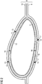
- Fig. 2 shows a mold 8 in cross-section for manufacturing one of the wind turbine blades three of Fig. 1 .
- the mold 8 comprises a lower mold component 9 and an upper mold component 10.
- the mold 8 is shown in Fig. 2 in a closed state in which the upper mold component 10 is arranged on the lower mold component 9.
- a dry fiber lay-up 11 is arranged in the mold 10.
- the fiber lay-up 11 may also comprise a core material and/or reinforcement beams (not shown). Additionally, also a shear web may be arranged in the mold 8 (not shown).
- step S1 of the method the fiber lay-up 11 is casted by a known vacuum infusion process.
- the fiber lay-up 11 is covered with a vacuum bag 12 ( Fig. 2 ).
- a vacuum is generated in a space covered by the vacuum bag 12.
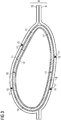
- one or more resin inlet channels 13 are opened, and resin 14 is infused into the fiber lay-up 11 due to the generated vacuum ( Fig. 3 ).
- the resin 14 is cured resulting in a fiber reinforced resin laminate structure.
- Fig. 2 shows sensors 15 arranged in the internal structure of the mold 8.
- the mold 8 comprises several boreholes 17 having an opening towards an inner surface 18 of the mold 8.
- Each of the sensors 15 is arranged in one of the boreholes 17 such that the respective sensor 15 is flush with the inner surface 18 of the mold 8.
- Fig. 2 shows sensors 16 arranged within the fiber lay-up 11, i.e. embedded in the fiber lay-up 11.
- the mold 8 may comprise one or more or all of the shown sensors 15, 16.
- the mold 8 may also comprise additional sensors not show in the figures.
- Fig. 4 shows a first example of monitoring the resin infusion process based on sensor data obtained with one or more of the sensors 15 and/or of the sensors 16 shown in Figs. 2 and 3 .
- the sensor 15, 16 are distributed - in addition to a circumferential direction, as shown in Figs. 2 and 3 - also along a longitudinal direction L of the blade 3 at longitudinal positions X0, X1, X2, X3, X4 and X5.
- step S2 of the method sensor data are obtained by the sensors 15, 16.
- Step S2 can be performed before step S1, simultaneously with S1 or after step S1.
- sensor data such as the temperature of the mold 8 could be obtained (step S2). This allows to start the resin infusion (step S1) only when the mold 8 has an appropriate temperature.
- sensor data of the mold 8, the fiber lay-up 11 or the resin 14 could be obtained (step S2) during the infusion and/or curing of the resin 14 (step S1).
- step S3 the obtained sensor data are processed by a computing unit (not shown) included, for example, in an augmented reality device 19.
- the sensors are, for example, connected wireless with the computing unit in the augmented reality device 19.
- the sensor data are, for example, interpreted and interpolated using data analytics models to prepare for visualization.
- the data are, in the example of Fig. 4 , processed to derive a spatial distribution of a flow front of the resin 14.
- step S4 the processed sensor data are displayed in the augmented reality device 19.
- the augmented reality device of Fig. 4 is in the form of augmented reality glasses 19 (AR-glasses) worn by a worker 20.
- the obtained and processed sensor data are displayed in the AR-glasses 19 overlaid onto a digital three-dimensional representation 21 of the blade 3.
- Fig. 4 shows a worker 20 who is monitoring the manufacturing process of the blade 3.
- the worker 20 is standing in front of the closed mold 8 (see Figs. 2 and 3 ) and cannot look inside the mold 8.
- information about the infusion process is nevertheless made available for the worker 20 by means of the AR-glasses 19.
- Fig. 4 shows an example of what the worker 20 sees in the display of the AR-glasses 19.
- the worker 20 sees the three-dimensional model 21 of the blade 3 the AR-glasses 19.
- overlaid onto the three-dimensional model 21 are processed sensor data representing the flow front 22 ( Fig. 4 ) of the infused resin 14 flowing through the fiber lay-up 11 ( Fig. 3 ).
- the worker 20 with the AR-glasses 20 can walk around the closed mold 8 and inspect the wetting process of the fiber lay-up 11, 11'.
- the AR-glasses 19 are equipped with a tracking system (not shown) which is capturing visual data of the closed mold 8 ( Fig. 3 ) and is able to recognize the mold shape for tracking and subsequent overlay of augmented information in form of the resin flow front 22 ( Fig. 4 ).
- the worker 20 monitors in step S5 the resin infusion process and/or the resin curing process based on the processed sensor data displayed in the AR-glasses 19.
- the worker 20 recognizes, for example, that the resin flow front 22 is not developing as required, she can take measures to alter the infusion process in step S6. For example, if the worker 20 recognizes that there remain dry spots of the fiber lay-up 11 in certain areas, the mold 8 could be locally heated up. Heating up the mold 8 affects the viscosity of the resin 14. With higher temperature, the viscosity of the resin 14 decreases and, thus, the resin flow is improved.
- the mold 8 ( Fig. 2 , 3 ) comprises resin inlet channels 13 in addition to the longitudinal position X0 also at one or more of the further longitudinal positions X1 to X5 ( Fig. 4 ).
- the worker 20 could monitor the resin infusion process and as soon as the resin flow front 22 reaches or passes a certain position x1 to X5, a resin inlet channel at this position could be opened.
- Fig. 5 shows another example of monitoring a resin infusion and/or curing process.
- the worker 20 sees in the AR-glasses 19 the three-dimensional model 21 of the blade 3.
- processed sensor data representing a temperature distribution 25 ( Fig. 4 ) of, for example, the inner surface 18 of the mold 8 ( Fig. 2 ).
Landscapes
- Engineering & Computer Science (AREA)
- Mechanical Engineering (AREA)
- Composite Materials (AREA)
- Chemical & Material Sciences (AREA)
- Physics & Mathematics (AREA)
- Computer Graphics (AREA)
- General Engineering & Computer Science (AREA)
- Software Systems (AREA)
- Computer Hardware Design (AREA)
- General Physics & Mathematics (AREA)
- Theoretical Computer Science (AREA)
- Health & Medical Sciences (AREA)
- Oral & Maxillofacial Surgery (AREA)
- Thermal Sciences (AREA)
- Moulding By Coating Moulds (AREA)
- Casting Or Compression Moulding Of Plastics Or The Like (AREA)
Abstract
Description
- The present invention relates to a method for manufacturing a wind turbine blade.
- Wind turbine rotor blades usually comprise a fiber-reinforced laminate structure. The fiber-reinforced laminate structure is manufactured by wetting a fiber lay-up with resin and curing the resin. The wetting process includes, for example, infusing the fibers with resin. The quality of the manufactured fiber-reinforced laminate highly depends on several parameters related to the infusion and curing process such as temperature and pressure of the resin. For example, the temperature dependent viscosity of the resin influences the resin flow through the fibers. Therefore, monitoring the parameters influencing the infusion and curing process is desirable. Further, wind turbine blades can be manufactured in a closed mold preventing a visual inspection of the resin flow and the curing process during the manufacturing process.
- It is one object of the present invention to provide an improved method for manufacturing a wind turbine blade.
- Accordingly, a method for manufacturing a wind turbine blade is proposed. The method comprises the step of monitoring a process of infusing and/or curing a fiber lay-up with resin in a mold. The monitoring is based on sensor data obtained from the resin infusion and/or curing process displayed in an augmented reality device.
- Displaying sensor data obtained from the resin infusion and/or curing process in an augmented reality device allows to better monitor the resin infusion and/or curing process. It allows a real-time visualization of the process. In particular, insight into the current state of the infused resin and/or of the curing of the resin during the manufacturing process can be obtained. Therefore, parameters influencing the infusion and/or curing process can be controlled. Thus, the quality of the manufactured wind turbine blade can be improved. For example, a uniform distribution of the resin throughout the fibers can be better achieved. For example, it can be better prevented that portions of the fibers remain dry, i.e. without resin. Another example is that the occurrence of enclosed air bubbles in the laminate can be reduced. Therefore, a strength and durability of the laminate structure can be improved.
- The wind turbine blade is part of a rotor of a wind turbine. The wind turbine is an apparatus to convert the wind's kinetic energy into electrical energy. The wind turbine comprises, for example, the rotor having one or more of the blades connected each to a hub, a nacelle including a generator, and a tower holding, at its top end, the nacelle. The tower of the wind turbine may be connected via a transition piece to a foundation of the wind turbine, such as a monopile in the seabed.
- The wind turbine blade, e.g., its root section, is fixedly or rotatably connected to the hub. Apart from the (cylindrical) root section, the wind turbine blade is formed aerodynamically. The wind turbine blade comprises, for example, a pressure side (upwind side) and a suction side (downwind side). The pressure side and the suction side are connected with each other at a leading edge and a trailing edge. The pressure and suctions sides and the leading and trailing edges define an airfoil of the wind turbine blade.
- The wind turbine blade is, for example, manufactured by arranging the fiber lay-up in the mold, infusing the fiber lay-up with resin, and curing the resin.
- The fibers are, for example, arranged in the mold in a dry condition, i. e. as fibers without a resin. The fibers may also be (partially) pre-impregnated fibers (prepreg). The fibers include, for example, glass fibers, carbon fibers, aramid fibers and/or natural fibers.
The fiber lay-up may include a fiber core material, such as wood, balsa, PET foam and/or PVC foam. The core material may be sandwiched between layers of fibers such that a fiber-reinforced resin laminate with a core structure is obtained. - Further, reinforcement beams may be arranged in the mold and connected to the fiber lay-up by the resin infusion and curing.
- The resin is infused into the fiber lay-up, for example, by a vacuum-assisted resin infusion process. For example, the fiber lay-up is covered with a vacuum bag and a vacuum is generated in a space covered by the vacuum bag, e.g. in a space between the mold and the vacuum bag. The resin is then infused into this space due to the generated vacuum, thus wetting the fibers.
- The mold may comprise a lower mold component and an upper mold component. A fiber lay-up for forming a lower shell of the blade (e.g., a pressure side of the blade) may be arranged in the lower mold, and a fiber lay-up for forming an upper shell of the blade (e.g., a suction side of the blade) may be arranged in the upper mold. The upper mold may be arranged on the lower mold, thus forming a cavity between them. The mold may also comprise a mold core in the mold cavity. The fiber lay-ups in the lower and upper molds may be covered by a vacuum bag. Resin may be infused in a space between the vacuum bag and the lower and upper molds in the closed state of the mold, i.e. with the upper mold arranged on the lower mold.
- The resin includes, for example, thermosets, thermoplastics, epoxy, polyurethane, vinyl ester and/or polyester.
- The resin is, for example, cured by applying heat. The result is a fiber-reinforced resin laminate.
- Monitoring the process of infusing and/or curing the fiber lay-up with resin based on the sensor data displayed in the augmented reality device includes, for example, inspecting the displayed sensor data. It may include detecting a deviation of the displayed sensor data from a desired state. It may include an alert system to indicate such a deviation.
- The sensor data include measurement data obtained by one or more sensors. The one or more sensors are arranged at or close to the mold, the fibers, the resin and/or their nearby environment. The one or more sensors are connected, wired or wireless, with the augmented reality device. For example, the one or more sensors are connected, wired or wireless, via a computing unit with the augmented reality device. The computing unit may be an external hardware computing unit being separate from the augmented reality device. Alternatively, the augmented reality device itself may include the computing unit. The computing unit may also include a cloud-based computing unit.
- The augmented reality device comprises a monitor to display the sensor data. The augmented reality device includes, for example, augmented reality glasses, a tablet, a laptop, a mobile phone and/or a projector.
- An augmented reality device is, in particular, a device, which allows to display real-world information to a user, the real-world information being augmented in a computer-assisted manner. Displaying the sensor data in the augmented reality device includes, in particular, displaying the sensor measurement data as augmented information overlaid onto a representation of the mold or the blade. It is also possible to display the sensor data in a virtual reality device or by a projection with a projector onto the mold or the blade during manufacturing.
- According to an embodiment, the sensor data include a measured physical quantity of the mold, of the fiber lay-up arranged in the mold and/or of the resin.
- This allows to monitor a physical quantity of the mold, the fiber lay-up and/or the resin which is influencing the infusion and/or curing process.
- The sensor data may also include a measured physical quantity of a nearby environment of the mold, the fiber lay-up and/or the resin.
- According to a further embodiment, the physical quantity includes temperature, pressure, current position of the resin, viscosity, refractive index, density, electric properties and/or dielectric properties.
- Monitoring the temperature of the mold, the fiber lay-up and/or the resin allows to control, for example, the temperature of the resin such that the temperature-dependent viscosity of the resin is suitable for the desired resin flow.
- Monitoring the pressure, and thus the generated vacuum, e.g., in the space covered by the vacuum bag, allows to control the resin flow and/or to detect a resin leakage.
- Monitoring the current position of the resin allows to control a flow front of the resin during infusion.
- Monitoring the density of the resin and/or the refractive index of the resin (which is related to the density of the resin), allows to control the curing state of the resin.
- Monitoring electric and/or dielectric properties of the resin, which depend on structural properties of the resin, allows to control the curing state of the resin.
- According to a further embodiment, the sensor data include a chemical information of the resin.
- This allows, for example, to control a curing state of the resin.
According to a further embodiment, the sensor data include location data and/or time data. - The sensor data may include in addition to sensor measurement data obtained by the one or more sensors (such as measured physical of chemical quantities of the mold, the fiber lay-up and/or the resin) also location data indicating the location of where the measured quantity was measured, i.e. where the measured is present. For example, a temperature sensor may be placed in a specific location within the fiber lay-up, then the sensor data include the measured temperature at this location and the spatial coordinates of this location.
- Furthermore, the sensor data may include also time data indicating the time when the measurement data were obtained.
- Having the location data allows to display the measurement data as function of the location data. Thus, it allows to display, for example, a spatial distribution of the measurement data. For example, a temperature distribution of the mold may be displayed.
- Having the time data allows to display the measurement data as function of the time data. Thus, it allows to display a timely evolution of the measurement data. For example, a development of a flow front of the resin can be displayed.
- According to a further embodiment, the sensor data displayed in the augmented reality device are processed sensor data including a temperature distribution, a pressure distribution, a resin flow front representation and/or a resin curing representation.
- The sensor data obtained from the resin infusion and/or curing process may be stored and processed by a computing unit. The data may, for example, be interpreted and interpolated using data analytics models to prepare for visualization. The data may, for example, be processed in order to derive from a measured quantity a physical or chemical quantity of interest. The data may, for example, be processed to derive a spatial and/or timely distribution of a quantity, such as a spatial temperature distribution, a spatial pressure distribution, a spatial resin flow front state, a spatial resin curing state, a temperature evolution, a pressure evolution, a resin flow front evolution and/or a resin curing evolution.
- By displaying the processed sensor data in the augmented reality device and, thereby, monitoring the processed sensor data, the resin infusion and/or curing process can be better controlled.
- According to embodiments, the sensor data are displayed in the augmented reality device overlaid onto a real-world representation of the mold and/or of the blade.
- The user of the augmented reality device, e.g., augmented reality glasses, sees, for example, the real mold and/or blade during manufacturing as well as the sensor data as augmented information overlaid onto it.
- According to a further embodiment, the sensor data are displayed in the augmented reality device overlaid onto digital data of the mold and/or of the blade.
- The digital data may be visual data of the mold and/or of the blade during manufacturing. The visual data are, in particular, obtained by a camera. The camera may be included in the augmented reality device or may be separate from the augmented reality device. The camera, for example the augmented reality device including the camera, may include a tracking system to track the relative position of the camera to the mold and/or the blade. For example, a marker-based or model-based tracking may be used. The tracking may be done by capturing visual data (video stream or frames of the video stream) through the camera and analyzing the visual data by means of a computer algorithm and, for example, said computing unit. Based on the computer algorithm, the mold shape and/or blade shape during manufacturing may be recognized in the visual data for tracking and subsequent overlay of augmented information in the form of the sensor data. In this case, the augmented reality device displays the sensor data overlaid on the camera-based visual data of the mold or the blade during manufacturing.
- The digital data may also be a three-dimensional model of the mold and/or of the blade. In this case, the augmented reality device displays the sensor data overlaid on the three-dimensional model of the mold and/or of the blade.
- Displaying the sensor data in the augmented reality device overlaid onto the digital data of the mold and/or of the blade allows an intuitive and illustrative recognition of the complex process of the resin infusion and/or curing. Further, it can be seen as a direct instruction of how to control the resin infusion and/or curing process.
- According to a further embodiment, the sensor data are collected by a sensor arranged in the internal structure of the mold and/or at an inner surface of the mold.
- This allows to better control quantities of the mold, such as a temperature of the mold which significantly influences the resin flow.
- For example, one or more sensors are arranged within boreholes of the mold. For example, the boreholes may have an opening towards the inner surface of the mold, and the one or more sensors are arranged within the boreholes such that they are flush with the inner surface of the mold.
- According to a further embodiment, the sensor data are collected by a sensor arranged on and/or within the fiber lay-up.
- This allows to better measure a quantity of the fiber lay-up and/or of the incoming resin.
According to a further embodiment, at least a portion of the sensor remains in the infused and cured fiber lay-up of the manufactured blade. - This allows to measure sensor data within the fiber lay-up, e.g., in the internal structure of the fiber lay-up, without the need to remove the sensor later.
- For example, an optical fiber may be used as sensor, and (a portion of) the optical fiber remains in the manufactured blade.
- According to a further embodiment, the method comprises, after the step of monitoring, the step of altering the resin infusion process based on the monitoring result.
- This allows to modify the infusion and/or curing process based on the sensor data displayed in the augmented reality device. The infusion and/or curing process may be promptly manipulated based on the sensor data displayed in the augmented reality device. For example, it allows to intervene when process parameters are unsuitable or unfortunate for the production of the wind turbine blade.
- According to a further embodiment, the resin infusion process is altered by opening a resin inlet channel, heating the mold and/or increasing the infusion pressure.
- For example, as soon as the mold temperature is suitable, one or more first resin inlet channels might be opened to start the resin infusion.
- A further example is that the mold may comprise several resin inlet channels configured for being opened subsequently. The several resin inlet channels might be distributed along a longitudinal direction and/or along a circumferential direction of the mold. After one or more first resin inlet channels of the several resin inlet channels have been opened to start the resin infusion, further resin inlet channels might be opened depending on the monitored resin flow.
- A further example is that if it is detected that there are dry spots of the fibers, the mold may be heated locally in an environment of the detected dry spot to decrease the viscosity of the resin and cause it to flow to the still dry spot.
- Further possible implementations or alternative solutions of the invention also encompass combinations - that are not explicitly mentioned herein - of features described above or below with regard to the embodiments. The person skilled in the art may also add individual or isolated aspects and features to the most basic form of the invention.
- Further embodiments, features and advantages of the present invention will become apparent from the subsequent description and dependent claims, taken in conjunction with the accompanying drawings, in which:
-
Fig. 1 shows a wind turbine according to an embodiment; -
Fig. 2 shows a cross-section view of a mold for manufacturing a wind turbine blade of the wind turbine ofFig. 1 ; -
Fig. 3 shows a view similar asFig. 2 but with resin partly infused into a fiber lay-up of the blade; -
Fig. 4 shows a three-dimensional image of the blade of the wind turbine ofFig. 1 overlaid with augmented information from the manufacturing process as seen through an augmented reality device according to an embodiment; -
Fig. 5 shows a three-dimensional image of the blade of the wind turbine ofFig. 1 overlaid with augmented information from the manufacturing process as seen through an augmented reality device according to another embodiment; and -
Fig. 6 shows a flowchart illustrating a method for manufacturing the wind turbine blade of the wind turbine ofFig. 1 . - In the Figures, like reference numerals designate like or functionally equivalent elements, unless otherwise indicated.
- Although the present invention has been described in accordance with preferred embodiments, it is obvious for the person skilled in the art that modifications are possible in all embodiments.
-
Fig. 1 shows a wind turbine 1 according to an embodiment. The wind turbine 1 comprises a rotor 2 having one or more blades 3 connected to a hub 4. The hub 4 is connected to a generator (not shown) arranged inside a nacelle 5. During operation of the wind turbine 1, the blades 3 are driven by wind to rotate and the wind's kinetic energy is converted into electrical energy by the generator in the nacelle 5. The nacelle 5 is arranged at the upper end of atower 6 of the wind turbine 1. Thetower 6 is erected on afoundation 7 such as a monopile or tripile. Thefoundation 7 is connected to and/or driven into the ground or seabed. - In the following an improved method for manufacturing a wind turbine blade 3 is described with respect to
Figs. 2 to 6 . -
Fig. 2 shows amold 8 in cross-section for manufacturing one of the wind turbine blades three ofFig. 1 . Themold 8 comprises alower mold component 9 and anupper mold component 10. Themold 8 is shown inFig. 2 in a closed state in which theupper mold component 10 is arranged on thelower mold component 9. Furthermore, a dry fiber lay-up 11 is arranged in themold 10. The fiber lay-up 11 may also comprise a core material and/or reinforcement beams (not shown). Additionally, also a shear web may be arranged in the mold 8 (not shown). - In step S1 of the method, the fiber lay-
up 11 is casted by a known vacuum infusion process. In this vacuum infusion process, the fiber lay-up 11 is covered with a vacuum bag 12 (Fig. 2 ). Then, a vacuum is generated in a space covered by thevacuum bag 12. Next, one or more resin inlet channels 13 (not visible in the cross-section view ofFig. 2 , only shown inFig. 4 ) are opened, andresin 14 is infused into the fiber lay-up 11 due to the generated vacuum (Fig. 3 ). Then, theresin 14 is cured resulting in a fiber reinforced resin laminate structure. - In order to monitor the resin infusion process and the resin curing process, there are
several sensors mold 8 and within the fiber lay-up 11. As an example,Fig. 2 showssensors 15 arranged in the internal structure of themold 8. Themold 8 comprisesseveral boreholes 17 having an opening towards aninner surface 18 of themold 8. Each of thesensors 15 is arranged in one of theboreholes 17 such that therespective sensor 15 is flush with theinner surface 18 of themold 8. - As a further example of the sensors,
Fig. 2 showssensors 16 arranged within the fiber lay-up 11, i.e. embedded in the fiber lay-up 11. Themold 8 may comprise one or more or all of the shownsensors mold 8 may also comprise additional sensors not show in the figures. -
Fig. 4 shows a first example of monitoring the resin infusion process based on sensor data obtained with one or more of thesensors 15 and/or of thesensors 16 shown inFigs. 2 and3 . In the example ofFig. 4 , thesensor Figs. 2 and3 - also along a longitudinal direction L of the blade 3 at longitudinal positions X0, X1, X2, X3, X4 and X5. - In step S2 of the method, sensor data are obtained by the
sensors Fig. 4 ) for starting the infusion (step S1), sensor data such as the temperature of themold 8 could be obtained (step S2). This allows to start the resin infusion (step S1) only when themold 8 has an appropriate temperature. In another example, sensor data of themold 8, the fiber lay-up 11 or theresin 14 could be obtained (step S2) during the infusion and/or curing of the resin 14 (step S1). - In step S3, the obtained sensor data are processed by a computing unit (not shown) included, for example, in an
augmented reality device 19. The sensors are, for example, connected wireless with the computing unit in theaugmented reality device 19. - The sensor data are, for example, interpreted and interpolated using data analytics models to prepare for visualization. The data are, in the example of
Fig. 4 , processed to derive a spatial distribution of a flow front of theresin 14. - In step S4, the processed sensor data are displayed in the
augmented reality device 19. The augmented reality device ofFig. 4 is in the form of augmented reality glasses 19 (AR-glasses) worn by aworker 20. The obtained and processed sensor data are displayed in the AR-glasses 19 overlaid onto a digital three-dimensional representation 21 of the blade 3. -
Fig. 4 shows aworker 20 who is monitoring the manufacturing process of the blade 3. In reality, theworker 20 is standing in front of the closed mold 8 (seeFigs. 2 and3 ) and cannot look inside themold 8. However, information about the infusion process is nevertheless made available for theworker 20 by means of the AR-glasses 19.Fig. 4 shows an example of what theworker 20 sees in the display of the AR-glasses 19. Theworker 20 sees the three-dimensional model 21 of the blade 3 the AR-glasses 19. Furthermore, overlaid onto the three-dimensional model 21 are processed sensor data representing the flow front 22 (Fig. 4 ) of the infusedresin 14 flowing through the fiber lay-up 11 (Fig. 3 ). Areas of the fiber lay-up 11' which are already wetted withresin 14, i.e. impregnated parts of the blade 3, are denoted with 23 inFig. 4 . Areas of the fiber lay-up 11 which are still dry are denoted with 24 inFig. 4 . - The
worker 20 with the AR-glasses 20 can walk around theclosed mold 8 and inspect the wetting process of the fiber lay-up 11, 11'. The AR-glasses 19 are equipped with a tracking system (not shown) which is capturing visual data of the closed mold 8 (Fig. 3 ) and is able to recognize the mold shape for tracking and subsequent overlay of augmented information in form of the resin flow front 22 (Fig. 4 ). - The
worker 20 monitors in step S5 the resin infusion process and/or the resin curing process based on the processed sensor data displayed in the AR-glasses 19. - In case that the
worker 20 recognizes, for example, that theresin flow front 22 is not developing as required, she can take measures to alter the infusion process in step S6. For example, if theworker 20 recognizes that there remain dry spots of the fiber lay-up 11 in certain areas, themold 8 could be locally heated up. Heating up themold 8 affects the viscosity of theresin 14. With higher temperature, the viscosity of theresin 14 decreases and, thus, the resin flow is improved. - In embodiments, the mold 8 (
Fig. 2 ,3 ) comprisesresin inlet channels 13 in addition to the longitudinal position X0 also at one or more of the further longitudinal positions X1 to X5 (Fig. 4 ). In this case, theworker 20 could monitor the resin infusion process and as soon as theresin flow front 22 reaches or passes a certain position x1 to X5, a resin inlet channel at this position could be opened. -
Fig. 5 shows another example of monitoring a resin infusion and/or curing process. As in the example ofFig. 4 , theworker 20 sees in the AR-glasses 19 the three-dimensional model 21 of the blade 3. Furthermore, overlaid onto this three-dimensional model are processed sensor data representing a temperature distribution 25 (Fig. 4 ) of, for example, theinner surface 18 of the mold 8 (Fig. 2 ).
Claims (12)
- Method for manufacturing a wind turbine blade (3), comprising the step of monitoring (S5) a process of infusing and/or curing (S1) a fiber lay-up (11) with resin (14) in a mold (8), wherein the monitoring (S5) is based on sensor data (22, 25) obtained (S2) from the resin infusion and/or curing process displayed (S4) in an augmented reality device (19).
- The method according to claim 1, wherein the sensor data (22, 25) include a measured physical quantity of the mold (8), of the fiber lay-up (11) arranged in the mold (8) and/or of the resin (14).
- The method according to claim 2, wherein the physical quantity includes temperature, pressure, current position of the resin (14), viscosity, refractive index, density, electric properties and/or dielectric properties.
- The method according to one of claims 1 - 3, wherein the sensor data (22, 25) include a chemical information of the resin (14).
- The method according to one of claims 1 - 4, wherein the sensor data (22, 25) include location data and/or time data.
- The method according to one of claims 1 - 5, wherein the sensor data (22, 25) displayed in the augmented reality device (19) are processed sensor data (22, 25) including a temperature distribution, a pressure distribution, a resin flow front representation and/or a resin curing representation.
- The method according to one of claims 1 - 6, wherein the sensor data (22, 25) are displayed in the augmented reality device (19) overlaid onto digital data (21) of the mold (8) and/or of the blade (3).
- The method according to one of claims 1 - 7, wherein the sensor data (22, 25) are collected by a sensor (15) arranged in the internal structure of the mold (8) and/or at an inner surface (18) of the mold (8).
- The method according to one of claims 1 - 8, wherein the sensor data (22, 25) are collected by a sensor (16) arranged on and/or within the fiber lay-up (11, 11').
- The method according to claim 9, wherein at least a portion of the sensor (16) remains in the infused and cured fiber lay-up (11') of the manufactured blade (3).
- The method according to one of claims 1 - 10, comprising, after the step of monitoring (S5), the step of altering (S6) the resin infusion process based on the monitoring result.
- The method according to claim 11, wherein the resin infusion process is altered (S6) by opening a resin inlet channel (13), heating the mold (8) and/or increasing the infusion pressure.
Priority Applications (7)
| Application Number | Priority Date | Filing Date | Title |
|---|---|---|---|
| PT201661964T PT3885117T (en) | 2020-03-27 | 2020-03-27 | Method for manufacturing a wind turbine blade |
| PL20166196.4T PL3885117T3 (en) | 2020-03-27 | 2020-03-27 | Method for manufacturing a wind turbine blade |
| DK20166196.4T DK3885117T3 (en) | 2020-03-27 | 2020-03-27 | Method for manufacturing a wind turbine blade |
| EP20166196.4A EP3885117B1 (en) | 2020-03-27 | 2020-03-27 | Method for manufacturing a wind turbine blade |
| ES20166196T ES3013865T3 (en) | 2020-03-27 | 2020-03-27 | Method for manufacturing a wind turbine blade |
| US17/212,472 US11691360B2 (en) | 2020-03-27 | 2021-03-25 | Method for manufacturing a wind turbine blade |
| CN202110326544.7A CN113442464B (en) | 2020-03-27 | 2021-03-26 | Method for manufacturing a wind turbine blade |
Applications Claiming Priority (1)
| Application Number | Priority Date | Filing Date | Title |
|---|---|---|---|
| EP20166196.4A EP3885117B1 (en) | 2020-03-27 | 2020-03-27 | Method for manufacturing a wind turbine blade |
Publications (2)
| Publication Number | Publication Date |
|---|---|
| EP3885117A1 true EP3885117A1 (en) | 2021-09-29 |
| EP3885117B1 EP3885117B1 (en) | 2024-12-11 |
Family
ID=70056869
Family Applications (1)
| Application Number | Title | Priority Date | Filing Date |
|---|---|---|---|
| EP20166196.4A Active EP3885117B1 (en) | 2020-03-27 | 2020-03-27 | Method for manufacturing a wind turbine blade |
Country Status (7)
| Country | Link |
|---|---|
| US (1) | US11691360B2 (en) |
| EP (1) | EP3885117B1 (en) |
| CN (1) | CN113442464B (en) |
| DK (1) | DK3885117T3 (en) |
| ES (1) | ES3013865T3 (en) |
| PL (1) | PL3885117T3 (en) |
| PT (1) | PT3885117T (en) |
Cited By (1)
| Publication number | Priority date | Publication date | Assignee | Title |
|---|---|---|---|---|
| CN116080108A (en) * | 2023-02-17 | 2023-05-09 | 浙江恒亿达复合材料有限公司 | Data acquisition management system for production process of wind power glass fiber pultrusion plate |
Family Cites Families (7)
| Publication number | Priority date | Publication date | Assignee | Title |
|---|---|---|---|---|
| US4828472A (en) * | 1983-12-16 | 1989-05-09 | Kawasaki Jukogyo Kabushiki Kaisha | Apparatus for molding and solidifying a resinous composite structure |
| ES2853374T3 (en) | 2014-01-31 | 2021-09-15 | Lm Wp Patent Holding As | Method for manufacturing a wind turbine blade part in two steps |
| CN103847072B (en) * | 2014-02-14 | 2015-10-28 | 江苏恒神股份有限公司 | The RTM mold of resin heating flow channel |
| EP3118604B1 (en) | 2015-07-14 | 2019-03-27 | Airbus Defence and Space GmbH | Testing device for controlling component production |
| GB201611866D0 (en) * | 2016-07-07 | 2016-08-24 | Hexcel Composites Ltd | Improvements in or relating to infusion moulding |
| DE102018104519A1 (en) * | 2018-02-28 | 2019-08-29 | Deutsches Zentrum für Luft- und Raumfahrt e.V. | Apparatus and method for monitoring infiltration during manufacture of a fiber-plastic composite component |
| CN110328868B (en) * | 2019-07-05 | 2020-09-22 | 国电联合动力技术(连云港)有限公司 | Full-automatic intelligent vacuum filling system and method for fan blade |
-
2020
- 2020-03-27 DK DK20166196.4T patent/DK3885117T3/en active
- 2020-03-27 EP EP20166196.4A patent/EP3885117B1/en active Active
- 2020-03-27 PL PL20166196.4T patent/PL3885117T3/en unknown
- 2020-03-27 PT PT201661964T patent/PT3885117T/en unknown
- 2020-03-27 ES ES20166196T patent/ES3013865T3/en active Active
-
2021
- 2021-03-25 US US17/212,472 patent/US11691360B2/en active Active
- 2021-03-26 CN CN202110326544.7A patent/CN113442464B/en active Active
Non-Patent Citations (3)
| Title |
|---|
| ARNOLD KOETJE: ""First-time-right"; Realtime visualisation infusion using augmented reality", 31 May 2018 (2018-05-31), XP055726368, Retrieved from the Internet <URL:http://inhollandcomposites.nl/wp-content/uploads/2018/05/FTR-realtime-visualisation-infusion-using-augmented-reality-iss2-sept2018.pdf> [retrieved on 20200831] * |
| GINGER GARDINER: "Sensors for monitoring resin infusion flow front and cure", COMPOSITESWORLD, 27 February 2018 (2018-02-27), XP055726360, Retrieved from the Internet <URL:https://www.compositesworld.com/articles/sensors-for-monitoring-resin-infusion-flow-front-and-cure> [retrieved on 20200831] * |
| INHOLLAND COMPOSITES: "Augmented Reality Gimmick or Game Changer", 30 October 2019 (2019-10-30), pages 1, XP054980838, Retrieved from the Internet <URL:https://www.youtube.com/watch?v=r39DpojM5n8> [retrieved on 20200901] * |
Cited By (2)
| Publication number | Priority date | Publication date | Assignee | Title |
|---|---|---|---|---|
| CN116080108A (en) * | 2023-02-17 | 2023-05-09 | 浙江恒亿达复合材料有限公司 | Data acquisition management system for production process of wind power glass fiber pultrusion plate |
| CN116080108B (en) * | 2023-02-17 | 2023-07-25 | 浙江恒亿达复合材料有限公司 | Data acquisition management system for production process of wind power glass fiber pultrusion plate |
Also Published As
| Publication number | Publication date |
|---|---|
| DK3885117T3 (en) | 2025-02-24 |
| EP3885117B1 (en) | 2024-12-11 |
| PL3885117T3 (en) | 2025-04-07 |
| US11691360B2 (en) | 2023-07-04 |
| CN113442464B (en) | 2025-05-02 |
| PT3885117T (en) | 2025-03-10 |
| ES3013865T3 (en) | 2025-04-15 |
| US20210299980A1 (en) | 2021-09-30 |
| CN113442464A (en) | 2021-09-28 |
Similar Documents
| Publication | Publication Date | Title |
|---|---|---|
| US20240078654A1 (en) | System and method for inspection of a wind turbine blade shell part | |
| CN111336073A (en) | Wind driven generator tower clearance visual monitoring device and method | |
| EP2913180A1 (en) | System and method for resin flow control | |
| US11691360B2 (en) | Method for manufacturing a wind turbine blade | |
| EP3638478B1 (en) | Method for manufacturing wind turbine rotor blade components using dynamic mold heating | |
| DK2838711T3 (en) | A method of making a composite part and an apparatus for making a composite part | |
| WO2019048597A1 (en) | Method for analysis of sensor data related to a wind turbine | |
| CN115202236B (en) | Flywheel operation risk monitoring system and method | |
| CN118582356B (en) | Method and system for monitoring respiratory deformation of blade based on machine vision | |
| EP4103392B1 (en) | Method for manufacturing a wind turbine blade and mold for manufacturing a wind turbine blade | |
| US20170078841A1 (en) | Wind turbine inspection | |
| CA3210548A1 (en) | Production system, method and computer program product | |
| CN112364684B (en) | A computer room server state acquisition and three-dimensional management and control system and method | |
| CN205135913U (en) | String of a musical instrument locating template and setting angle of blade measurement system of wind turbine generator system blade | |
| CN109060172A (en) | Sandwich component lightning damage monitoring device and method based on interplantation fiber grating | |
| US20130270729A1 (en) | Resin flow control in vartm process | |
| US20250312978A1 (en) | Method for manufacturing a wind turbine blade and mold arrangement | |
| CN115059587A (en) | Internet of things real-time monitoring and early warning system based on 5G communication | |
| EP3969748B1 (en) | A method and an apparatus for computer-implemented monitoring of one or more wind turbines in a wind farm | |
| US11821404B2 (en) | Method and an apparatus for computer-implemented monitoring of one or more wind turbines in a wind farm | |
| CN118832193A (en) | Metal printer composite flexible scanning printing parameter control method and system | |
| CN120936484A (en) | Wind turbine blade fabrication using smart imaging | |
| EP3502467A1 (en) | Wind turbine rotor blade with embedded sensors stitched to drapable plies | |
| EP4542030A1 (en) | Method for detecting at least one property of a component of or for a wind turbine | |
| CN118911949B (en) | A method for controlling ice melting of wind turbine blades |
Legal Events
| Date | Code | Title | Description |
|---|---|---|---|
| PUAI | Public reference made under article 153(3) epc to a published international application that has entered the european phase |
Free format text: ORIGINAL CODE: 0009012 |
|
| STAA | Information on the status of an ep patent application or granted ep patent |
Free format text: STATUS: REQUEST FOR EXAMINATION WAS MADE |
|
| 17P | Request for examination filed |
Effective date: 20210203 |
|
| AK | Designated contracting states |
Kind code of ref document: A1 Designated state(s): AL AT BE BG CH CY CZ DE DK EE ES FI FR GB GR HR HU IE IS IT LI LT LU LV MC MK MT NL NO PL PT RO RS SE SI SK SM TR |
|
| GRAP | Despatch of communication of intention to grant a patent |
Free format text: ORIGINAL CODE: EPIDOSNIGR1 |
|
| STAA | Information on the status of an ep patent application or granted ep patent |
Free format text: STATUS: GRANT OF PATENT IS INTENDED |
|
| RIC1 | Information provided on ipc code assigned before grant |
Ipc: B29L 31/08 20060101ALN20240701BHEP Ipc: B29C 70/48 20060101ALI20240701BHEP Ipc: G06T 19/00 20110101ALI20240701BHEP Ipc: B29C 35/02 20060101ALI20240701BHEP Ipc: B29C 70/44 20060101ALI20240701BHEP Ipc: B29D 99/00 20100101AFI20240701BHEP |
|
| INTG | Intention to grant announced |
Effective date: 20240718 |
|
| GRAS | Grant fee paid |
Free format text: ORIGINAL CODE: EPIDOSNIGR3 |
|
| GRAA | (expected) grant |
Free format text: ORIGINAL CODE: 0009210 |
|
| STAA | Information on the status of an ep patent application or granted ep patent |
Free format text: STATUS: THE PATENT HAS BEEN GRANTED |
|
| AK | Designated contracting states |
Kind code of ref document: B1 Designated state(s): AL AT BE BG CH CY CZ DE DK EE ES FI FR GB GR HR HU IE IS IT LI LT LU LV MC MK MT NL NO PL PT RO RS SE SI SK SM TR |
|
| REG | Reference to a national code |
Ref country code: GB Ref legal event code: FG4D |
|
| REG | Reference to a national code |
Ref country code: CH Ref legal event code: EP |
|
| REG | Reference to a national code |
Ref country code: DE Ref legal event code: R096 Ref document number: 602020042853 Country of ref document: DE |
|
| REG | Reference to a national code |
Ref country code: IE Ref legal event code: FG4D |
|
| REG | Reference to a national code |
Ref country code: DK Ref legal event code: T3 Effective date: 20250221 |
|
| REG | Reference to a national code |
Ref country code: NL Ref legal event code: FP |
|
| REG | Reference to a national code |
Ref country code: PT Ref legal event code: SC4A Ref document number: 3885117 Country of ref document: PT Date of ref document: 20250310 Kind code of ref document: T Free format text: AVAILABILITY OF NATIONAL TRANSLATION Effective date: 20250303 |
|
| REG | Reference to a national code |
Ref country code: LT Ref legal event code: MG9D |
|
| PG25 | Lapsed in a contracting state [announced via postgrant information from national office to epo] |
Ref country code: HR Free format text: LAPSE BECAUSE OF FAILURE TO SUBMIT A TRANSLATION OF THE DESCRIPTION OR TO PAY THE FEE WITHIN THE PRESCRIBED TIME-LIMIT Effective date: 20241211 |
|
| PG25 | Lapsed in a contracting state [announced via postgrant information from national office to epo] |
Ref country code: FI Free format text: LAPSE BECAUSE OF FAILURE TO SUBMIT A TRANSLATION OF THE DESCRIPTION OR TO PAY THE FEE WITHIN THE PRESCRIBED TIME-LIMIT Effective date: 20241211 |
|
| PGFP | Annual fee paid to national office [announced via postgrant information from national office to epo] |
Ref country code: NL Payment date: 20250325 Year of fee payment: 6 |
|
| REG | Reference to a national code |
Ref country code: ES Ref legal event code: FG2A Ref document number: 3013865 Country of ref document: ES Kind code of ref document: T3 Effective date: 20250415 |
|
| PG25 | Lapsed in a contracting state [announced via postgrant information from national office to epo] |
Ref country code: BG Free format text: LAPSE BECAUSE OF FAILURE TO SUBMIT A TRANSLATION OF THE DESCRIPTION OR TO PAY THE FEE WITHIN THE PRESCRIBED TIME-LIMIT Effective date: 20241211 |
|
| PG25 | Lapsed in a contracting state [announced via postgrant information from national office to epo] |
Ref country code: NO Free format text: LAPSE BECAUSE OF FAILURE TO SUBMIT A TRANSLATION OF THE DESCRIPTION OR TO PAY THE FEE WITHIN THE PRESCRIBED TIME-LIMIT Effective date: 20250311 |
|
| PG25 | Lapsed in a contracting state [announced via postgrant information from national office to epo] |
Ref country code: GR Free format text: LAPSE BECAUSE OF FAILURE TO SUBMIT A TRANSLATION OF THE DESCRIPTION OR TO PAY THE FEE WITHIN THE PRESCRIBED TIME-LIMIT Effective date: 20250312 Ref country code: LV Free format text: LAPSE BECAUSE OF FAILURE TO SUBMIT A TRANSLATION OF THE DESCRIPTION OR TO PAY THE FEE WITHIN THE PRESCRIBED TIME-LIMIT Effective date: 20241211 |
|
| PGFP | Annual fee paid to national office [announced via postgrant information from national office to epo] |
Ref country code: PL Payment date: 20250311 Year of fee payment: 6 |
|
| PG25 | Lapsed in a contracting state [announced via postgrant information from national office to epo] |
Ref country code: RS Free format text: LAPSE BECAUSE OF FAILURE TO SUBMIT A TRANSLATION OF THE DESCRIPTION OR TO PAY THE FEE WITHIN THE PRESCRIBED TIME-LIMIT Effective date: 20250311 |
|
| REG | Reference to a national code |
Ref country code: AT Ref legal event code: MK05 Ref document number: 1750097 Country of ref document: AT Kind code of ref document: T Effective date: 20241211 |
|
| PG25 | Lapsed in a contracting state [announced via postgrant information from national office to epo] |
Ref country code: SM Free format text: LAPSE BECAUSE OF FAILURE TO SUBMIT A TRANSLATION OF THE DESCRIPTION OR TO PAY THE FEE WITHIN THE PRESCRIBED TIME-LIMIT Effective date: 20241211 |
|
| PGFP | Annual fee paid to national office [announced via postgrant information from national office to epo] |
Ref country code: ES Payment date: 20250423 Year of fee payment: 6 |
|
| PG25 | Lapsed in a contracting state [announced via postgrant information from national office to epo] |
Ref country code: IS Free format text: LAPSE BECAUSE OF FAILURE TO SUBMIT A TRANSLATION OF THE DESCRIPTION OR TO PAY THE FEE WITHIN THE PRESCRIBED TIME-LIMIT Effective date: 20250411 |
|
| PG25 | Lapsed in a contracting state [announced via postgrant information from national office to epo] |
Ref country code: EE Free format text: LAPSE BECAUSE OF FAILURE TO SUBMIT A TRANSLATION OF THE DESCRIPTION OR TO PAY THE FEE WITHIN THE PRESCRIBED TIME-LIMIT Effective date: 20241211 |
|
| PG25 | Lapsed in a contracting state [announced via postgrant information from national office to epo] |
Ref country code: RO Free format text: LAPSE BECAUSE OF FAILURE TO SUBMIT A TRANSLATION OF THE DESCRIPTION OR TO PAY THE FEE WITHIN THE PRESCRIBED TIME-LIMIT Effective date: 20241211 Ref country code: AT Free format text: LAPSE BECAUSE OF FAILURE TO SUBMIT A TRANSLATION OF THE DESCRIPTION OR TO PAY THE FEE WITHIN THE PRESCRIBED TIME-LIMIT Effective date: 20241211 |
|
| PG25 | Lapsed in a contracting state [announced via postgrant information from national office to epo] |
Ref country code: SK Free format text: LAPSE BECAUSE OF FAILURE TO SUBMIT A TRANSLATION OF THE DESCRIPTION OR TO PAY THE FEE WITHIN THE PRESCRIBED TIME-LIMIT Effective date: 20241211 |
|
| PG25 | Lapsed in a contracting state [announced via postgrant information from national office to epo] |
Ref country code: CZ Free format text: LAPSE BECAUSE OF FAILURE TO SUBMIT A TRANSLATION OF THE DESCRIPTION OR TO PAY THE FEE WITHIN THE PRESCRIBED TIME-LIMIT Effective date: 20241211 |
|
| PG25 | Lapsed in a contracting state [announced via postgrant information from national office to epo] |
Ref country code: IT Free format text: LAPSE BECAUSE OF FAILURE TO SUBMIT A TRANSLATION OF THE DESCRIPTION OR TO PAY THE FEE WITHIN THE PRESCRIBED TIME-LIMIT Effective date: 20241211 |
|
| PG25 | Lapsed in a contracting state [announced via postgrant information from national office to epo] |
Ref country code: SE Free format text: LAPSE BECAUSE OF FAILURE TO SUBMIT A TRANSLATION OF THE DESCRIPTION OR TO PAY THE FEE WITHIN THE PRESCRIBED TIME-LIMIT Effective date: 20241211 |
|
| REG | Reference to a national code |
Ref country code: DE Ref legal event code: R097 Ref document number: 602020042853 Country of ref document: DE |
|
| PG25 | Lapsed in a contracting state [announced via postgrant information from national office to epo] |
Ref country code: MC Free format text: LAPSE BECAUSE OF FAILURE TO SUBMIT A TRANSLATION OF THE DESCRIPTION OR TO PAY THE FEE WITHIN THE PRESCRIBED TIME-LIMIT Effective date: 20241211 |
|
| PLBE | No opposition filed within time limit |
Free format text: ORIGINAL CODE: 0009261 |
|
| STAA | Information on the status of an ep patent application or granted ep patent |
Free format text: STATUS: NO OPPOSITION FILED WITHIN TIME LIMIT |
|
| REG | Reference to a national code |
Ref country code: CH Ref legal event code: L10 Free format text: ST27 STATUS EVENT CODE: U-0-0-L10-L00 (AS PROVIDED BY THE NATIONAL OFFICE) Effective date: 20251022 |
|
| REG | Reference to a national code |
Ref country code: CH Ref legal event code: H13 Free format text: ST27 STATUS EVENT CODE: U-0-0-H10-H13 (AS PROVIDED BY THE NATIONAL OFFICE) Effective date: 20251023 |
|
| PG25 | Lapsed in a contracting state [announced via postgrant information from national office to epo] |
Ref country code: LU Free format text: LAPSE BECAUSE OF NON-PAYMENT OF DUE FEES Effective date: 20250327 |
|
| 26N | No opposition filed |
Effective date: 20250912 |
|
| REG | Reference to a national code |
Ref country code: BE Ref legal event code: MM Effective date: 20250331 |
|
| PG25 | Lapsed in a contracting state [announced via postgrant information from national office to epo] |
Ref country code: BE Free format text: LAPSE BECAUSE OF NON-PAYMENT OF DUE FEES Effective date: 20250331 |
|
| PG25 | Lapsed in a contracting state [announced via postgrant information from national office to epo] |
Ref country code: CH Free format text: LAPSE BECAUSE OF NON-PAYMENT OF DUE FEES Effective date: 20250331 |
|
| PG25 | Lapsed in a contracting state [announced via postgrant information from national office to epo] |
Ref country code: IE Free format text: LAPSE BECAUSE OF NON-PAYMENT OF DUE FEES Effective date: 20250327 |
|
| PGFP | Annual fee paid to national office [announced via postgrant information from national office to epo] |
Ref country code: GB Payment date: 20260323 Year of fee payment: 7 |
|
| PGFP | Annual fee paid to national office [announced via postgrant information from national office to epo] |
Ref country code: DE Payment date: 20250829 Year of fee payment: 7 Ref country code: DK Payment date: 20260323 Year of fee payment: 7 |
|
| PGFP | Annual fee paid to national office [announced via postgrant information from national office to epo] |
Ref country code: FR Payment date: 20260323 Year of fee payment: 7 |
|
| PGFP | Annual fee paid to national office [announced via postgrant information from national office to epo] |
Ref country code: PT Payment date: 20260306 Year of fee payment: 7 |