EP3885033A1 - Method and system for the treatment of materials - Google Patents
Method and system for the treatment of materials Download PDFInfo
- Publication number
- EP3885033A1 EP3885033A1 EP19888053.6A EP19888053A EP3885033A1 EP 3885033 A1 EP3885033 A1 EP 3885033A1 EP 19888053 A EP19888053 A EP 19888053A EP 3885033 A1 EP3885033 A1 EP 3885033A1
- Authority
- EP
- European Patent Office
- Prior art keywords
- treatment system
- chamber
- kinematic pair
- fluid state
- fluid
- Prior art date
- Legal status (The legal status is an assumption and is not a legal conclusion. Google has not performed a legal analysis and makes no representation as to the accuracy of the status listed.)
- Granted
Links
Images



Classifications
-
- B—PERFORMING OPERATIONS; TRANSPORTING
- B02—CRUSHING, PULVERISING, OR DISINTEGRATING; PREPARATORY TREATMENT OF GRAIN FOR MILLING
- B02C—CRUSHING, PULVERISING, OR DISINTEGRATING IN GENERAL; MILLING GRAIN
- B02C15/00—Disintegrating by milling members in the form of rollers or balls co-operating with rings or discs
- B02C15/12—Mills with at least two discs or rings and interposed balls or rollers mounted like ball or roller bearings
- B02C15/123—Mills with at least two discs or rings and interposed balls or rollers mounted like ball or roller bearings with rings and interposed rollers
-
- B—PERFORMING OPERATIONS; TRANSPORTING
- B01—PHYSICAL OR CHEMICAL PROCESSES OR APPARATUS IN GENERAL
- B01F—MIXING, e.g. DISSOLVING, EMULSIFYING OR DISPERSING
- B01F27/00—Mixers with rotary stirring devices in fixed receptacles; Kneaders
- B01F27/27—Mixers with stator-rotor systems, e.g. with intermeshing teeth or cylinders or having orifices
- B01F27/276—Mixers with stator-rotor systems, e.g. with intermeshing teeth or cylinders or having orifices the mixer being composed of a stator-rotor system being formed by bearing elements, e.g. roller bearings
-
- B—PERFORMING OPERATIONS; TRANSPORTING
- B01—PHYSICAL OR CHEMICAL PROCESSES OR APPARATUS IN GENERAL
- B01F—MIXING, e.g. DISSOLVING, EMULSIFYING OR DISPERSING
- B01F23/00—Mixing according to the phases to be mixed, e.g. dispersing or emulsifying
- B01F23/50—Mixing liquids with solids
- B01F23/53—Mixing liquids with solids using driven stirrers
-
- B—PERFORMING OPERATIONS; TRANSPORTING
- B01—PHYSICAL OR CHEMICAL PROCESSES OR APPARATUS IN GENERAL
- B01F—MIXING, e.g. DISSOLVING, EMULSIFYING OR DISPERSING
- B01F23/00—Mixing according to the phases to be mixed, e.g. dispersing or emulsifying
- B01F23/50—Mixing liquids with solids
- B01F23/55—Mixing liquids with solids the mixture being submitted to electrical, sonic or similar energy
- B01F23/551—Mixing liquids with solids the mixture being submitted to electrical, sonic or similar energy using vibrations
-
- B—PERFORMING OPERATIONS; TRANSPORTING
- B01—PHYSICAL OR CHEMICAL PROCESSES OR APPARATUS IN GENERAL
- B01F—MIXING, e.g. DISSOLVING, EMULSIFYING OR DISPERSING
- B01F31/00—Mixers with shaking, oscillating, or vibrating mechanisms
- B01F31/44—Mixers with shaking, oscillating, or vibrating mechanisms with stirrers performing an oscillatory, vibratory or shaking movement
-
- B—PERFORMING OPERATIONS; TRANSPORTING
- B01—PHYSICAL OR CHEMICAL PROCESSES OR APPARATUS IN GENERAL
- B01F—MIXING, e.g. DISSOLVING, EMULSIFYING OR DISPERSING
- B01F35/00—Accessories for mixers; Auxiliary operations or auxiliary devices; Parts or details of general application
- B01F35/30—Driving arrangements; Transmissions; Couplings; Brakes
- B01F35/32—Driving arrangements
- B01F35/32005—Type of drive
- B01F35/3204—Motor driven, i.e. by means of an electric or IC motor
-
- B—PERFORMING OPERATIONS; TRANSPORTING
- B01—PHYSICAL OR CHEMICAL PROCESSES OR APPARATUS IN GENERAL
- B01F—MIXING, e.g. DISSOLVING, EMULSIFYING OR DISPERSING
- B01F35/00—Accessories for mixers; Auxiliary operations or auxiliary devices; Parts or details of general application
- B01F35/90—Heating or cooling systems
- B01F35/92—Heating or cooling systems for heating the outside of the receptacle, e.g. heated jackets or burners
-
- B—PERFORMING OPERATIONS; TRANSPORTING
- B01—PHYSICAL OR CHEMICAL PROCESSES OR APPARATUS IN GENERAL
- B01J—CHEMICAL OR PHYSICAL PROCESSES, e.g. CATALYSIS OR COLLOID CHEMISTRY; THEIR RELEVANT APPARATUS
- B01J8/00—Chemical or physical processes in general, conducted in the presence of fluids and solid particles; Apparatus for such processes
- B01J8/18—Chemical or physical processes in general, conducted in the presence of fluids and solid particles; Apparatus for such processes with fluidised particles
- B01J8/1836—Heating and cooling the reactor
-
- B—PERFORMING OPERATIONS; TRANSPORTING
- B01—PHYSICAL OR CHEMICAL PROCESSES OR APPARATUS IN GENERAL
- B01F—MIXING, e.g. DISSOLVING, EMULSIFYING OR DISPERSING
- B01F35/00—Accessories for mixers; Auxiliary operations or auxiliary devices; Parts or details of general application
- B01F35/30—Driving arrangements; Transmissions; Couplings; Brakes
- B01F2035/35—Use of other general mechanical engineering elements in mixing devices
- B01F2035/351—Sealings
-
- B—PERFORMING OPERATIONS; TRANSPORTING
- B01—PHYSICAL OR CHEMICAL PROCESSES OR APPARATUS IN GENERAL
- B01F—MIXING, e.g. DISSOLVING, EMULSIFYING OR DISPERSING
- B01F2101/00—Mixing characterised by the nature of the mixed materials or by the application field
- B01F2101/2805—Mixing plastics, polymer material ingredients, monomers or oligomers
-
- B—PERFORMING OPERATIONS; TRANSPORTING
- B01—PHYSICAL OR CHEMICAL PROCESSES OR APPARATUS IN GENERAL
- B01F—MIXING, e.g. DISSOLVING, EMULSIFYING OR DISPERSING
- B01F2101/00—Mixing characterised by the nature of the mixed materials or by the application field
- B01F2101/30—Mixing paints or paint ingredients, e.g. pigments, dyes, colours, lacquers or enamel
-
- B—PERFORMING OPERATIONS; TRANSPORTING
- B01—PHYSICAL OR CHEMICAL PROCESSES OR APPARATUS IN GENERAL
- B01J—CHEMICAL OR PHYSICAL PROCESSES, e.g. CATALYSIS OR COLLOID CHEMISTRY; THEIR RELEVANT APPARATUS
- B01J2208/00—Processes carried out in the presence of solid particles; Reactors therefor
- B01J2208/00008—Controlling the process
- B01J2208/00017—Controlling the temperature
- B01J2208/00106—Controlling the temperature by indirect heat exchange
- B01J2208/00168—Controlling the temperature by indirect heat exchange with heat exchange elements outside the bed of solid particles
- B01J2208/00203—Coils
-
- B—PERFORMING OPERATIONS; TRANSPORTING
- B01—PHYSICAL OR CHEMICAL PROCESSES OR APPARATUS IN GENERAL
- B01J—CHEMICAL OR PHYSICAL PROCESSES, e.g. CATALYSIS OR COLLOID CHEMISTRY; THEIR RELEVANT APPARATUS
- B01J2208/00—Processes carried out in the presence of solid particles; Reactors therefor
- B01J2208/00796—Details of the reactor or of the particulate material
- B01J2208/00823—Mixing elements
- B01J2208/00858—Moving elements
-
- B—PERFORMING OPERATIONS; TRANSPORTING
- B02—CRUSHING, PULVERISING, OR DISINTEGRATING; PREPARATORY TREATMENT OF GRAIN FOR MILLING
- B02C—CRUSHING, PULVERISING, OR DISINTEGRATING IN GENERAL; MILLING GRAIN
- B02C15/00—Disintegrating by milling members in the form of rollers or balls co-operating with rings or discs
- B02C15/12—Mills with at least two discs or rings and interposed balls or rollers mounted like ball or roller bearings
- B02C2015/126—Mills with at least two discs or rings and interposed balls or rollers mounted like ball or roller bearings of the plural stage type
Definitions
- the present invention is applicable to industrial processes intended for improving the properties of materials, for example and in a non-limiting manner, polymer materials.
- the present invention relates to a method and system for the treatment of materials, said materials being selected from between materials in a fluid state and particles suspended in a fluid material, by means of the application of high shear rates and/or hydrostatic pressures, allowing the physical, chemical, and/or mechanical properties of said materials or other materials derived therefrom (for example, following polymerisation) to be improved without the need to add reinforcement particles or other similar improvement elements to that end.
- a particular embodiment of the present invention relates to a mixing method for mixing a material in a fluid state with particles suspended in said fluid material at high shear rates and/or hydrostatic pressures.
- Said embodiment is applicable, for example and in a non-limiting manner, to processes for manufacturing paint, as well as to processes for manufacturing materials that are improved/reinforced by means of particles and nanoparticles, and to processes for obtaining said particles and nanoparticles.
- the embodiments of the invention allow obtaining shear rates and hydrostatic pressures that are significantly higher than those contemplated in the state of the art by about two orders of magnitude, even three orders of magnitude in some cases.
- reinforcement particles are often added to said material when it is in a fluid state to improve its physical, chemical, and/or structural properties.
- Said materials may preferably comprise a matrix of starting material, for example and in a non-limiting manner, a polymer material, such as an epoxy resin or a polycarbonate.
- a polymer material such as an epoxy resin or a polycarbonate.
- the resulting mixture formed by the material in a fluid state and the reinforcement particles, then usually solidifies by means of processes such as polymerisation, sintering, cooling, etc.
- the materials obtained as a result of said mixing and subsequent solidification process are usually called "composites”.
- the degree by which the properties of the materials comprising polymer materials are improved by means of the addition of reinforcement particles, such as carbon nanotubes and/or graphene or graphene oxide nanoparticles, depends largely on the following factors: the level of delamination of the reinforcement particles, the level of dispersion of the reinforcement particles, and the quality of the interfaces generated between the reinforcement particles and the polymer material.
- the reinforcement particles mentioned in the preceding paragraph are often formed by stacks of several different sheets.
- the more the sheets are separated from one another i.e., the higher the level of delamination), the better the properties of the resulting nanocomposite material will be.
- the more the linear nanoparticles are separated from one another i.e., the higher the level of disentanglement), the better the properties of the resulting material will be.
- the mixture formed in this case by the polymer material in a fluid state and the suspended reinforcement particles, is often subjected to high shear rates to increase the level of delamination or disentanglement of the reinforcement particles. Therefore, for example, by using a Rannie Gaulin 110T homogeniser marketed by AXFlow Holding AB, shear rates of the order of 10 5 s -1 can be obtained. At these shear rates, many of the sheets originally present in the reinforcement particles are delaminated, but not completely.
- the fluid material is a solvent in which graphite particles are suspended.
- the shear rates that can be obtained with the current systems do not allow completely delaminating all the graphene sheets forming the graphite particles.
- the level of delamination or disentanglement of the reinforcement particles would also improve by increasing the hydrostatic pressure to which the mixture is subjected.
- Rannie Gaulin 110T homogenisers available today, marketed by AXFlow Holding AB, are capable of applying hydrostatic pressures of the order of 0.15 GPa on the mixtures. It would therefore be advisable to develop new mixing methods for mixing reinforcement particles with materials in a fluid state, whereby higher hydrostatic pressures can be applied on the mixture formed by the material in a fluid state and the reinforcement particles.
- the lower the agglomeration of the reinforcement and/or improvement particles i.e., the higher the level of dispersion
- the better the properties of the resulting material will be.
- the mixture is often subjected to high shear rates to reduce the agglomeration of the reinforcement and/or improvement particles.
- the reinforcement/improvement particles and said matrix of starting material do not adhere well to one another, giving rise to the generated interfaces not having a good quality.
- Another way of improving the adhesion of the particles to the matrix which does not present the drawbacks associated with functionalisation is to increase the shear rate and/or hydrostatic pressure to which the mixture is subjected.
- high shear rates of the order of 10 4 - 10 5 s -1
- high hydrostatic pressure of the order of (0.01 - 0.15 GPa.
- devices such as ball mills, calenders, homogenisers (for example, devices of the Rannie Gaulin® brand, marketed by the company AXFlow Holding AB), and dissolver devices (for example, devices of the Dispermat® brand, marketed by the company VMA Getzmann GmbH) are often used.
- performing the mixing at high shear rates is particularly relevant to disperse the particles or nanoparticles used in manufacturing said paint which tend to agglomerate and/or to achieve modifications in said particles or nanoparticles, i.e., delamination, size reduction, etc.
- the "shear rate" to which a material in a fluid state or a mixture (formed by a material in a fluid state and suspended particles) is subjected must be understood to mean the spatial gradient of velocity distribution, i.e., the magnitude of the variation of velocity of the material in a fluid state (or alternatively of the mixture) between two points very close to one another.
- hydrostatic pressure to which a material in a fluid state or a mixture (formed by a material in a fluid state and suspended particles) is subjected must be understood to mean the compression to which the fluid material is subjected, and in the case of a mixture, said pressure also includes the compression to which the particles suspended in the fluid material are subjected.
- a "kinematic pair” is a set of two mechanical elements which are in contact with one another with a specific contact force, with one furthermore being moved with respect to the other at a specific relative velocity.
- An upper kinematic pair is a kinematic pair in which the contact is theoretically a linear or point contact, also called a "Hertzian” contact such as, for example and in a non-limiting manner, the rolling element-race pair in the bearings, as well as those found in gears, cam-follower mechanisms, pin-on-disk tribometers, and ball-on-disk tribometers.
- a lower kinematic pair is one in which contact occurs on a surface such as, for example, the shaft-bearing pair.
- the contact that actually occurs between the two elements of the pair is not strictly a point or linear contact, but rather will be an elliptical contact (the ellipse having very short axes of the order of microns to hundreds of microns) or a rectangular contact (one of the sides of the rectangle having a very short length of the order of microns to hundreds of microns).
- a film of said material in a fluid state (or alternatively a film of the mixture formed by the material in a fluid state and the suspended particles) can be created between both elements of the pair, causing both elements to no longer be in contact.
- the actual contact will not be strictly a linear or point contact (or, in fact, there may be no contact at all), but the kinematic pair created by said elements are still formally called an "upper” or a "lower” pair.
- nanoparticle must be understood to mean a particle in which at least one of its dimensions has a size between 0.1 and 100 nanometres.
- a first object of the present invention relates to a system for the treatment of materials, said materials being selected from between materials in a fluid state and particles suspended in a fluid material, characterised in that it comprises:
- each upper kinematic pair would be subjected to a hydrodynamic lubrication regimen or limit by the material in a fluid state.
- the system for the treatment of materials in a fluid state comprises upper kinematic pairs formed by at least one bearing equipped with rolling elements arranged between a moving ring and a fixed ring.
- said bearing comprises a cage for separating the rolling elements.
- the system for the treatment of materials in a fluid state comprises at least one upper kinematic pair formed by a gear, a cam-follower mechanism, a chain-sprocket mechanism, a chain transmission, a belt transmission, a cable transmission, a pin-on-disk tribometer, or a ball-on-disk tribometer.
- the upper kinematic pair or alternatively, the upper kinematic pairs are housed in a chamber hermetically closed by a cover.
- the closed chamber is equipped with conduits for the entry and/or exit of material in a fluid state.
- the chamber can furthermore be equipped with at least one bore for the controlled entry and/or exit of gas.
- Said bores allow creating controlled vacuums inside the chamber, or alternatively, introducing gases in said chamber with a controlled pressure and temperature and chemical composition.
- the chamber can be equipped with at least one window allowing the access of electromagnetic or acoustic radiation, for example, ultrasound, to the inside of the chamber.
- electromagnetic or acoustic radiation for example, ultrasound
- the system for the treatment of materials according to the present invention can be optionally equipped with a coil through which a heat exchange fluid circulates. Said coil allows controlling the temperature of the material in a fluid state.
- Said coil can be arranged inside the chamber, or alternatively, in the outer part of the chamber, in contact with the walls of the chamber.
- the heat exchange between the inside of the chamber and the coil occurs by convection and radiation.
- some embodiments of the system for the treatment of materials according to the present invention contemplate that the chamber is at least partially submerged in a fluid which is at a pre-set temperature.
- the motor means comprise a motor connected to a transmission shaft and configured such that said motor is capable of transmitting an angular velocity to said transmission shaft, said shaft accessing the inside of the chamber through an opening provided in the cover body and the shaft being configured such that the shaft can transmit said angular velocity to the mechanical elements of the kinematic pair.
- said cover preferably further comprises a retainer and an O-ring.
- additional components assure the tightness of the cover, preventing the material in a fluid state from being able to undesirably come out of the chamber through said cover and simultaneously preventing air or other gases from being able to undesirably enter said chamber.
- the chamber comprises a chamber body for housing the material in a fluid state and a sleeve and a washer for fixing the kinematic pairs.
- the tensioning means of the system according to the invention preferably comprise a fixed base on which the chamber is arranged and a moving platform movable by means of tightening devices so as to exert pressure on the cover of the chamber, the tightening devices being controlled by an actuating device.
- the tensioning means are preferably furthermore equipped with:
- the system for the treatment of materials according to the present invention can optionally be equipped with load cells preferably arranged between the chamber and the fixed base.
- thermocouple intended for measuring the temperature of the material in a fluid state.
- the system for the treatment of materials according to the present invention can be optionally equipped with vibrating means for subjecting the kinematic pair (or alternatively the kinematic pairs) to a vibratory movement. Said vibratory movement contributes to increasing the contact pressure to which the kinematic pairs are subjected.
- a second object of the present invention relates to a method for the treatment of materials, selected from between materials in a fluid state and particles suspended in a fluid material, in a treatment system according to the first object of the invention, characterised in that it comprises the following steps:
- the material in a fluid state is a polymer material. More preferably, said polymer material contains polycarbonates, epoxy resin, bismaleimide, polyester, vinyl ester, phenolic resin, PEEK, ABS, PP, PE, urethane, or any combination thereof, including each one individually.
- the material in a fluid state is a polymer precursor, preferably a precursor of epoxy resin, bismaleimide, polyester, vinyl ester, phenolic resin, PEEK, ABS, PP, PE, urethane, or any combination thereof, including each one individually.
- the suspended particles are made of graphite.
- the purpose of this particular embodiment of the invention is to delaminate the graphite by means of the treatment system of the invention so as to obtain graphene.
- the obtained graphene may have higher levels of delamination and/or disentanglement and/or fragmentation of the particles, in comparison with the mixing methods known today.
- a third object of the present invention relates to a mixing method for mixing a material in a fluid state with suspended particles in a system for the treatment of materials in a fluid state according to the first object of the invention, characterised in that it comprises the following steps:
- this mixing method by contacting the upper kinematic pair or pairs with a mixture (formed by the material in a fluid state and the suspended particles) and applying a sufficiently high force and relative rolling and/or sliding velocity between the mechanical elements of each pair, a hydrodynamic wedge is formed between said mechanical elements which may lead to said mechanical elements separating from one another, such that the mixture is capable of moving between the two mechanical elements of each pair, forming a film of very small thickness (of the order of ones, tens or hundreds of nanometres) between them.
- the suspended particles are preferably reinforcement particles and more preferably, reinforcement nanoparticles.
- said reinforcement nanoparticles are carbon nanotubes and/or graphene or graphene oxide nanoparticles.
- the suspended particles are made of graphite.
- the material in a fluid state comprises a matrix of starting material, preferably a polymer material. More preferably, said polymer material contains polycarbonates, epoxy resin, bismaleimide, polyester, vinyl ester, phenolic resin, PEEK, ABS, PP, PE, urethane, or any combination thereof, including each one individually.
- the material in a fluid state is a polymer precursor, preferably a precursor of epoxy resin, bismaleimide, polyester, vinyl ester, phenolic resin, PEEK, ABS, PP, PE, urethane, or any combination thereof, including each one individually.
- the material in a fluid state is a solvent.
- either the material in a fluid state or the mixture formed by the material in a fluid state and the suspended particles can be subjected to hydrodynamic pressures and shear rates that are significantly higher (by way of example and in a non-limiting manner, of the order of 1 - 6 GPa and 10 6 - 10 9 s -1 , respectively), than those which can be obtained with the already known mixing systems and methods. This is achieved as a result of the high pressure and relative velocity applied to the mechanical elements of the kinematic pairs, and of the very small thickness of the hydrodynamic wedge created between said mechanical elements due to the presence of the mixture.
- the surface of the theoretical contact area and the thickness of the mixture film would depend on the rigidities of the load-supporting elements, on the relative velocity between the mechanical elements of each pair, and on the viscosity of the mixture of the material in a fluid state and the suspended particles.
- These parameters may be calculated, in a manner that is obvious for a one skilled in the art, from the hydrodynamic (HD), elastohydrodynamic (EHD), or thermoelastohydrodynamic (TEHD) lubrication models, so in the mixing methods according to the invention, the shear rate and the hydrostatic pressure to which the mixture of fluid and suspended particles is subjected could be controlled independent of one another.
- Figure 1 shows an axial bearing 2 for use in an embodiment of a treatment system according to the present invention.
- Said bearing 2 is supported on a fixed base 8a and comprises rolling elements 2a which, in this particular case, are steel spheres, arranged between a moving ring 2b and a fixed ring 2c. To assure the separation between the different rolling elements 2a, the bearing 2 is furthermore equipped with a cage 2d.
- This figure also schematically illustrates how, in a treatment system according to the invention, an angular velocity w is imparted on the moving ring 2b and a contact pressure p is exerted on the moving ring 2b which pushes said ring against the fixed ring 2c.
- Figure 2 schematically shows the upper kinematic pairs present in the bearing 2 which, within a treatment system according to the present invention, is placed in contact with a material in a fluid state 1 which can contain suspended particles intended for being mixed with said fluid.
- the mechanical elements are the rolling elements 2a, the moving ring 2b, and the fixed ring 2c.
- a first film of fluid material 1 with a width h 1 is formed between the elements of the first kinematic pair and a second film of fluid material, with a width h 2 , is formed between the elements of the second kinematic pair.
- Figures 3A, 3B, and 3C show the main components provided in a treatment system according to the present invention.
- Figure 3A is a side elevational view
- Figure 3C is an ordered exploded view thereof.
- Figure 3B is in turn a cross-sectional view along line A.
- a chamber 4 housing therein, according to this particular embodiment of the treatment system of the invention, two axial bearings 2, each of which is equipped with rolling elements 2a, a moving ring 2b, and a fixed ring 2c, can be seen in said Figures 3A - 3C .
- the chamber 4 likewise houses the material in a fluid state 1. Obviously, in those cases in which the system for the treatment of materials according to the present invention is used for mixing a material in a fluid state 1 with suspended particles, the chamber 4 will house the mixture formed by the material in a fluid state and the suspended particles intended for being mixed with the material in a fluid state. Furthermore, said cover 4 comprises a body 4a, and a sleeve 4b and washer 4c allowing the radial fixing of the axial bearings 2.
- the chamber 4 is equipped with a cover 3 subjected to a pressure p, exerted by pressure means (not seen in Figures 3A-3C ).
- Said cover 3 comprises a body 3a equipped with a through hole allowing the passage of a shaft 5b.
- Said shaft 5b is part of the motor means 5 and is fitted with the moving rings 2b of each bearing, such that the angular velocity w generated by the motor means 5 is transmitted without friction to the moving rings 2b of each bearing 2.
- the shaft 5b is equipped with a protuberance 5c which maximises contact between said shaft 5b and the moving rings 2b so as to prevent relative movement, and therefore friction, between same.
- the cover 3 is subjected to the pressure p generated by tensioning means (not seen in Figures 3A - 3C ). Said pressure p is transmitted to the mechanical elements of the bearings 2 through the body 3a of the cover 3.
- the cover 3 is also equipped with a retainer 3b and an O-ring 3c which prevent the material in a fluid state 1 (or, as the case may be, the mixture formed by the material in a fluid state 1 and the suspended particles) from being able to seep out of the chamber 4 through the through hole present in the body 3a of the cover 3.
- the retainer 3b and the O-ring 3c also prevent the entry or exit of air or other gases with respect to the inside of the chamber 4.
- Figure 4 shows an ordered exploded view of a chamber 4 for use in a treatment system according to the present invention.
- the chamber 4 in addition to the body 4a, the sleeve 4b, and the washer 4c, the chamber 4 is also equipped with a bore 4d for the controlled entry and/or exit of gas, as well as a window 4e, allowing the access of electromagnetic or acoustic radiation, for example and in a non-limiting manner, ultrasound, to the inside of the chamber.
- the electromagnetic and/or acoustic radiations mentioned in the preceding paragraph are normally used to improve the dispersion of the particles in the fluid material and if the particles are nanoparticles, to furthermore improve the adhesion between said nanoparticles and the fluid material 1.
- FIG 5 shows an ordered exploded view of the cover 3 described in Figures 3A to 3C .
- said cover 3 comprises the body 3a, the retainer 3b, and the O-ring 3c.
- Figure 6 shows a particular embodiment of a treatment system according to the present invention which further comprises a coil 6, in addition to other components already explained in relation to other preceding figures.
- Said coil allows controlling the temperature of the fluid material 1, or as the case maybe, of the mixture formed by the fluid material 1 and the suspended particles.
- Figure 7 shows a particular embodiment of a treatment system according to the present invention which further comprises conduits 7 allowing the entry and/or exit of the fluid material 1, or as the case maybe, of the mixture formed by the fluid material 1 and the suspended particles, with respect to the inside of the chamber, in addition to other components already explained in relation to other preceding figures.
- Figure 8 shows a particular embodiment of a complete treatment system according to the present invention.
- the motor means 5 comprise a motor 5a connected to the shaft 5b through a coupling 5d. Therefore, when the motor 5a is actuated, the resulting driving torque is transmitted to the shaft 5b, such that said shaft 5b is capable of rotating at an angular velocity w (schematically illustrated in Figures 1 and 3A ).
- the chamber 4 containing the fluid material 1, or as the case maybe, the mixture of fluid material 1 and suspended particles is arranged on the fixed base 8a.
- the motor 5a is fixed to said fixed base 8a by means of a fixing element 5e.
- the pressure means 8 comprise, in addition to the fixed base 8a, a moving platform 8b which is capable of moving as a result of the action of an actuating device 8e (in this embodiment, a motor) which causes the rotation of tightening devices 8c which, in this embodiment of the invention, are screws coupled to threaded through portions provided in the moving platform 8b.
- an actuating device 8e in this embodiment, a motor
- tightening devices 8c which, in this embodiment of the invention, are screws coupled to threaded through portions provided in the moving platform 8b.
- speed reducers 8d can be arranged between the screws 8c and the actuating device 8e.
- Said reducers 8d allow amplifying the force which the screw can exert for one same pair of the actuating device 8e.
- a cardan joint 8f which allows equalising the rotating speed of the reducers 8d and guides 8g which allow the moving platform 8b to move parallel to the fixed base 8a.
- At least one load cell 9a intended for measuring the compressive force applied on the cover 3 by the tensioning means and at least one thermocouple 9b intended for measuring the temperature of the fluid material 1, or as the case maybe, of the mixture formed by the fluid material 1 and the suspended particles intended for being mixed with said fluid material 1.
Landscapes
- Chemical & Material Sciences (AREA)
- Chemical Kinetics & Catalysis (AREA)
- Dispersion Chemistry (AREA)
- Engineering & Computer Science (AREA)
- Combustion & Propulsion (AREA)
- Organic Chemistry (AREA)
- Food Science & Technology (AREA)
- Processing And Handling Of Plastics And Other Materials For Molding In General (AREA)
- Accessories For Mixers (AREA)
- Lubricants (AREA)
- Crushing And Grinding (AREA)
- Processes Of Treating Macromolecular Substances (AREA)
- Mixers With Rotating Receptacles And Mixers With Vibration Mechanisms (AREA)
- Physical Or Chemical Processes And Apparatus (AREA)
Abstract
Description
- The present invention is applicable to industrial processes intended for improving the properties of materials, for example and in a non-limiting manner, polymer materials.
- More particularly, the present invention relates to a method and system for the treatment of materials, said materials being selected from between materials in a fluid state and particles suspended in a fluid material, by means of the application of high shear rates and/or hydrostatic pressures, allowing the physical, chemical, and/or mechanical properties of said materials or other materials derived therefrom (for example, following polymerisation) to be improved without the need to add reinforcement particles or other similar improvement elements to that end.
- Likewise, a particular embodiment of the present invention relates to a mixing method for mixing a material in a fluid state with particles suspended in said fluid material at high shear rates and/or hydrostatic pressures. Said embodiment is applicable, for example and in a non-limiting manner, to processes for manufacturing paint, as well as to processes for manufacturing materials that are improved/reinforced by means of particles and nanoparticles, and to processes for obtaining said particles and nanoparticles.
- The embodiments of the invention allow obtaining shear rates and hydrostatic pressures that are significantly higher than those contemplated in the state of the art by about two orders of magnitude, even three orders of magnitude in some cases.
- In some processes for manufacturing materials, reinforcement particles are often added to said material when it is in a fluid state to improve its physical, chemical, and/or structural properties.
- Said materials may preferably comprise a matrix of starting material, for example and in a non-limiting manner, a polymer material, such as an epoxy resin or a polycarbonate.
- The resulting mixture, formed by the material in a fluid state and the reinforcement particles, then usually solidifies by means of processes such as polymerisation, sintering, cooling, etc. The materials obtained as a result of said mixing and subsequent solidification process are usually called "composites".
- Nevertheless, the addition of these reinforcement particles complicates the process of manufacturing the material and increases production costs. Therefore, it would be desirable to develop systems and methods for the treatment of materials in a fluid state which allow the physical, chemical, and/or structural properties of said materials to be improved without the need to add reinforcement and/or improvement particles to that end.
- By way of example and in a non-limiting manner, it is known that the addition of carbon nanotubes and/or graphene or graphene oxide nanoparticles to epoxy resin or polycarbonate matrices as reinforcement particles improves, among others, the following physical and/or structural properties: fracture energy, fatigue life, rigidity, tensile strength, thermal conductivity, and electrical conductivity. The materials obtained as a result of said mixing and subsequent solidification process are called "nanocomposites" (given that the reinforcement particles in this particular case are nanoparticles).
- Moreover, it is known that the degree by which the properties of the materials comprising polymer materials are improved by means of the addition of reinforcement particles, such as carbon nanotubes and/or graphene or graphene oxide nanoparticles, depends largely on the following factors: the level of delamination of the reinforcement particles, the level of dispersion of the reinforcement particles, and the quality of the interfaces generated between the reinforcement particles and the polymer material.
- The reinforcement particles mentioned in the preceding paragraph, particularly flat nanoparticles such as graphene, are often formed by stacks of several different sheets. The more the sheets are separated from one another (i.e., the higher the level of delamination), the better the properties of the resulting nanocomposite material will be. The same occurs with linear nanoparticles such as carbon nanotubes, given that they tend to entangle with one another. The more the linear nanoparticles are separated from one another (i.e., the higher the level of disentanglement), the better the properties of the resulting material will be.
- In the state of the art, the mixture, formed in this case by the polymer material in a fluid state and the suspended reinforcement particles, is often subjected to high shear rates to increase the level of delamination or disentanglement of the reinforcement particles. Therefore, for example, by using a Rannie Gaulin 110T homogeniser marketed by AXFlow Holding AB, shear rates of the order of 105s-1 can be obtained. At these shear rates, many of the sheets originally present in the reinforcement particles are delaminated, but not completely.
- The same method based on the application of high shear rates is used to obtain graphene sheets from the delamination of graphite. In this case, the fluid material is a solvent in which graphite particles are suspended. The shear rates that can be obtained with the current systems do not allow completely delaminating all the graphene sheets forming the graphite particles.
- It would therefore be desirable to develop new mixing methods for mixing reinforcement particles with materials in a fluid state, whereby higher shear rates can be obtained.
- Moreover, the level of delamination or disentanglement of the reinforcement particles would also improve by increasing the hydrostatic pressure to which the mixture is subjected.
- Rannie Gaulin 110T homogenisers available today, marketed by AXFlow Holding AB, are capable of applying hydrostatic pressures of the order of 0.15 GPa on the mixtures. It would therefore be advisable to develop new mixing methods for mixing reinforcement particles with materials in a fluid state, whereby higher hydrostatic pressures can be applied on the mixture formed by the material in a fluid state and the reinforcement particles.
- Likewise, some reinforcement and/or improvement particles tend to cluster together once they have been added to the liquid matrix of starting material.
- As seen above, the lower the agglomeration of the reinforcement and/or improvement particles (i.e., the higher the level of dispersion), the better the properties of the resulting material will be. In the state of the art, the mixture is often subjected to high shear rates to reduce the agglomeration of the reinforcement and/or improvement particles.
- Therefore, it would also be desirable to be able to obtain higher shear rates, for the purpose of achieving a higher degree of dispersion of the reinforcement and/or improvement particles.
- Sometimes, in materials comprising a matrix of starting material, the reinforcement/improvement particles and said matrix of starting material do not adhere well to one another, giving rise to the generated interfaces not having a good quality. There may be various causes, for example, the lack of chemical compatibility between the materials forming the reinforcement/improvement particles and the starting material of the matrix.
- Different techniques for improving the adhesion between the reinforcement particles and the matrix of starting material such as, for example, functionalisation, are known in the state of the art. Said technique consists of physically or chemically modifying the particles to improve the binding thereof to the atomic or molecular structure of the matrix. However, functionalisation is associated with several drawbacks, such as the appearance of defects in the reinforcement particles. This may cause the improvement of the properties of the composite material, which are associated with the improvement in the quality of the interface, to be partially cancelled due to the appearance of defects.
- Another way of improving the adhesion of the particles to the matrix which does not present the drawbacks associated with functionalisation is to increase the shear rate and/or hydrostatic pressure to which the mixture is subjected.
- This is an additional reason why it is advisable to develop mixing methods for mixing reinforcement/improvement particles with materials in a fluid state and, particularly, mixing methods for mixing reinforcement/improvement particles with materials in a fluid state comprising a matrix of starting material, whereby higher shear rates and/or higher hydrostatic pressures can be obtained with respect to the mixtures.
- Moreover, industrial processes for mixing particles with materials in a fluid state, in which there is a need to achieve a good dispersion of the particles in the material (or materials) in a fluid state and to thereby prevent the appearance of agglomerations, are used in other sectors of the industry, besides those that have already been mentioned.
- This is achieved by subjecting the mixture, formed by the material (or materials) in a fluid state and the suspended particles, to high shear rates (of the order of 104- 105s-1 ) and/or high hydrostatic pressure (of the order of (0.01 - 0.15 GPa). For this purpose, devices such as ball mills, calenders, homogenisers (for example, devices of the Rannie Gaulin® brand, marketed by the company AXFlow Holding AB), and dissolver devices (for example, devices of the Dispermat® brand, marketed by the company VMA Getzmann GmbH) are often used.
- In processes for manufacturing paint, performing the mixing at high shear rates is particularly relevant to disperse the particles or nanoparticles used in manufacturing said paint which tend to agglomerate and/or to achieve modifications in said particles or nanoparticles, i.e., delamination, size reduction, etc.
- Likewise, when a high shear rate and/or hydrostatic pressure is applied to a mixture formed by a material in a fluid state and suspended particles, fragmentation of said particles into other smaller particles (similarly to the fragmentation taking place in ball mills or calenders of the state of the art) may even occur if the conditions are suitable, resulting in a better mixing of the components.
- Throughout the present specification, the "shear rate" to which a material in a fluid state or a mixture (formed by a material in a fluid state and suspended particles) is subjected must be understood to mean the spatial gradient of velocity distribution, i.e., the magnitude of the variation of velocity of the material in a fluid state (or alternatively of the mixture) between two points very close to one another.
- Likewise, the "hydrostatic pressure" to which a material in a fluid state or a mixture (formed by a material in a fluid state and suspended particles) is subjected must be understood to mean the compression to which the fluid material is subjected, and in the case of a mixture, said pressure also includes the compression to which the particles suspended in the fluid material are subjected.
- Furthermore, a "kinematic pair" is a set of two mechanical elements which are in contact with one another with a specific contact force, with one furthermore being moved with respect to the other at a specific relative velocity. An upper kinematic pair is a kinematic pair in which the contact is theoretically a linear or point contact, also called a "Hertzian" contact such as, for example and in a non-limiting manner, the rolling element-race pair in the bearings, as well as those found in gears, cam-follower mechanisms, pin-on-disk tribometers, and ball-on-disk tribometers.
- A lower kinematic pair is one in which contact occurs on a surface such as, for example, the shaft-bearing pair.
- Evidently, in an upper kinematic pair, for contact forces that do not cause plastic deformation of the elements forming the pair, the contact that actually occurs between the two elements of the pair is not strictly a point or linear contact, but rather will be an elliptical contact (the ellipse having very short axes of the order of microns to hundreds of microns) or a rectangular contact (one of the sides of the rectangle having a very short length of the order of microns to hundreds of microns). Furthermore, when the elements forming the kinematic pair are in contact with a material in a fluid state in a system for the treatment of materials according to the present invention, as will be described in more detail below, a film of said material in a fluid state (or alternatively a film of the mixture formed by the material in a fluid state and the suspended particles) can be created between both elements of the pair, causing both elements to no longer be in contact. In other words, in two mechanical elements formally forming an upper kinematic pair, the actual contact will not be strictly a linear or point contact (or, in fact, there may be no contact at all), but the kinematic pair created by said elements are still formally called an "upper" or a "lower" pair.
- Lastly, throughout the present specification, a "nanoparticle" must be understood to mean a particle in which at least one of its dimensions has a size between 0.1 and 100 nanometres.
- To solve the problems described in relation to the prior art, a first object of the present invention relates to a system for the treatment of materials, said materials being selected from between materials in a fluid state and particles suspended in a fluid material, characterised in that it comprises:
- at least one upper kinematic pair equipped with two mechanical elements; said kinematic pair being in contact with a material in a fluid state or in contact with particles suspended in a fluid material;
- motor means to generate a relative velocity between the mechanical elements of said kinematic pair, and
- tensioning means to subject said kinematic pair to a pre-set contact pressure.
- It has been observed through experimentation that in the system for the treatment of materials of the present invention, by contacting the upper kinematic pair or pairs with a material in a fluid state and applying a sufficiently high force and relative rolling and/or sliding velocity between the mechanical elements of each pair, a hydrodynamic wedge is formed between said mechanical elements which may lead to said mechanical elements separating from one another, such that said material in a fluid state is capable of moving between the two mechanical elements of each pair, forming a film of very small thickness (of the order of ones, tens or hundreds of nanometres) between them.
- Due to the force and relative velocity applied to the mechanical elements of the kinematic pairs, and to the hydrodynamic wedge created between them as a result of the presence of the material in a fluid state, said material in a fluid state is surprisingly subjected, in this case, to extremely high hydrodynamic pressures and shear rates (by way of example and in a non-limiting manner, of the order of 1 - 6 GPa and 106 - 109 s-1, respectively).
- Without wishing to be bound in any case by theory, this is believed to be possible due to, among other factors, the hydrodynamic phenomena observed in lubricated Hertzian contacts. In fact, it is believed that in the system according to the invention, each upper kinematic pair would be subjected to a hydrodynamic lubrication regimen or limit by the material in a fluid state.
- It has been verified that when the material in a fluid state, particularly if it is a polymer-type material or a polymer precursor material, is subjected to high pressures and/or shear rates by means of the treatment system according to the present invention, some of its physicochemical characteristics, such as, for example and in a non-limiting manner, the length or physical or chemical configuration of the monomers or of the polymer chains present in said material, may be modified. These modifications may lead to an improvement of some properties of the material or of the polymer resulting from the polymerisation of said precursor, such as rigidity, strength, fracture energy, electrical or thermal conductivity, without the need to add any reinforcement particle to that end.
- In one embodiment of the invention, the system for the treatment of materials in a fluid state comprises upper kinematic pairs formed by at least one bearing equipped with rolling elements arranged between a moving ring and a fixed ring. Preferably, said bearing comprises a cage for separating the rolling elements.
- In another embodiment of the invention, the system for the treatment of materials in a fluid state comprises at least one upper kinematic pair formed by a gear, a cam-follower mechanism, a chain-sprocket mechanism, a chain transmission, a belt transmission, a cable transmission, a pin-on-disk tribometer, or a ball-on-disk tribometer.
- In a preferred embodiment of the invention, the upper kinematic pair, or alternatively, the upper kinematic pairs are housed in a chamber hermetically closed by a cover. In a more preferred embodiment of the invention, the closed chamber is equipped with conduits for the entry and/or exit of material in a fluid state.
- Optionally, the chamber can furthermore be equipped with at least one bore for the controlled entry and/or exit of gas. Said bores allow creating controlled vacuums inside the chamber, or alternatively, introducing gases in said chamber with a controlled pressure and temperature and chemical composition.
- Likewise, the chamber can be equipped with at least one window allowing the access of electromagnetic or acoustic radiation, for example, ultrasound, to the inside of the chamber.
- The system for the treatment of materials according to the present invention can be optionally equipped with a coil through which a heat exchange fluid circulates. Said coil allows controlling the temperature of the material in a fluid state.
- Said coil can be arranged inside the chamber, or alternatively, in the outer part of the chamber, in contact with the walls of the chamber. The heat exchange between the inside of the chamber and the coil occurs by convection and radiation.
- Alternatively, instead of being equipped with a heat exchange coil, some embodiments of the system for the treatment of materials according to the present invention contemplate that the chamber is at least partially submerged in a fluid which is at a pre-set temperature.
- In a preferred embodiment of the invention, the motor means comprise a motor connected to a transmission shaft and configured such that said motor is capable of transmitting an angular velocity to said transmission shaft, said shaft accessing the inside of the chamber through an opening provided in the cover body and the shaft being configured such that the shaft can transmit said angular velocity to the mechanical elements of the kinematic pair.
- In the mentioned embodiment of the invention, said cover preferably further comprises a retainer and an O-ring. These additional components (retainer and O-ring) assure the tightness of the cover, preventing the material in a fluid state from being able to undesirably come out of the chamber through said cover and simultaneously preventing air or other gases from being able to undesirably enter said chamber.
- In another preferred embodiment of the invention, the chamber comprises a chamber body for housing the material in a fluid state and a sleeve and a washer for fixing the kinematic pairs.
- The tensioning means of the system according to the invention preferably comprise a fixed base on which the chamber is arranged and a moving platform movable by means of tightening devices so as to exert pressure on the cover of the chamber, the tightening devices being controlled by an actuating device.
- The tensioning means are preferably furthermore equipped with:
- speed reducers arranged between the tightening devices and the actuating device (said speed reducers allow amplifying the force which the tightening devices can exert for one and the same driving torque generated by the actuating device);
- a cardan joint (said cardan joint allows synchronising the movement of the different tightening devices, causing all of them to move at the same speed), and
- guides for guiding the movement of the moving platform.
- To measure the pressure exerted by the tightening devices on the cover of the chamber, the system for the treatment of materials according to the present invention can optionally be equipped with load cells preferably arranged between the chamber and the fixed base.
- Optionally, it can also be equipped with at least of one thermocouple intended for measuring the temperature of the material in a fluid state.
- Lastly, the system for the treatment of materials according to the present invention can be optionally equipped with vibrating means for subjecting the kinematic pair (or alternatively the kinematic pairs) to a vibratory movement. Said vibratory movement contributes to increasing the contact pressure to which the kinematic pairs are subjected.
- A second object of the present invention relates to a method for the treatment of materials, selected from between materials in a fluid state and particles suspended in a fluid material, in a treatment system according to the first object of the invention, characterised in that it comprises the following steps:
- introducing in the system for the treatment of materials a material in a fluid state, such that at least one upper kinematic pair of the treatment system is in contact with said fluid material or in contact with said particles suspended in a fluid material;
- actuating the motor means to generate a pre-set relative velocity between the mechanical elements of said upper kinematic pair; and
- actuating the tensioning means to subject a kinematic pair to a pre-set contact pressure.
- Likewise, in a particular embodiment of the method for the treatment of materials in a fluid state according to the invention, the material in a fluid state is a polymer material. More preferably, said polymer material contains polycarbonates, epoxy resin, bismaleimide, polyester, vinyl ester, phenolic resin, PEEK, ABS, PP, PE, urethane, or any combination thereof, including each one individually.
- In another particular embodiment of the method for the treatment of materials according to the invention, the material in a fluid state is a polymer precursor, preferably a precursor of epoxy resin, bismaleimide, polyester, vinyl ester, phenolic resin, PEEK, ABS, PP, PE, urethane, or any combination thereof, including each one individually.
- In another additional embodiment of the method for the treatment of materials according to the present invention, the suspended particles are made of graphite. Preferably, the purpose of this particular embodiment of the invention is to delaminate the graphite by means of the treatment system of the invention so as to obtain graphene.
- As a result of the high force and high relative rolling and/or sliding velocity between the mechanical elements of the kinematic pairs which can be obtained by means of the system and method of the present invention, the obtained graphene may have higher levels of delamination and/or disentanglement and/or fragmentation of the particles, in comparison with the mixing methods known today.
- A third object of the present invention relates to a mixing method for mixing a material in a fluid state with suspended particles in a system for the treatment of materials in a fluid state according to the first object of the invention, characterised in that it comprises the following steps:
- introducing in the treatment system a material in a fluid state furthermore containing suspended particles intended for being mixed with said fluid material, such that at least one upper kinematic pair of the treatment system is in contact with said fluid material containing suspended particles;
- actuating the motor means to generate a pre-set relative velocity between the mechanical elements of said upper kinematic pair; and
- actuating the tensioning means to subject said kinematic pair to a pre-set contact pressure.
- Like in other embodiments of the present invention, in this mixing method, by contacting the upper kinematic pair or pairs with a mixture (formed by the material in a fluid state and the suspended particles) and applying a sufficiently high force and relative rolling and/or sliding velocity between the mechanical elements of each pair, a hydrodynamic wedge is formed between said mechanical elements which may lead to said mechanical elements separating from one another, such that the mixture is capable of moving between the two mechanical elements of each pair, forming a film of very small thickness (of the order of ones, tens or hundreds of nanometres) between them.
- All this allows higher levels of delamination and/or disentanglement and/or dispersion and/or fragmentation of the particles and/or of adhesion thereof with the fluid material to be obtained in the mixing method according to the present invention, in comparison with the mixing methods known today.
- In the mixing method according to the invention, the suspended particles are preferably reinforcement particles and more preferably, reinforcement nanoparticles. In an even more preferred embodiment of the invention, said reinforcement nanoparticles are carbon nanotubes and/or graphene or graphene oxide nanoparticles.
- Likewise, in another preferred embodiment of the mixing method of the invention, the suspended particles are made of graphite.
- Likewise, in a particular embodiment of the mixing method according to the invention, the material in a fluid state comprises a matrix of starting material, preferably a polymer material. More preferably, said polymer material contains polycarbonates, epoxy resin, bismaleimide, polyester, vinyl ester, phenolic resin, PEEK, ABS, PP, PE, urethane, or any combination thereof, including each one individually.
- In another particular embodiment of the present mixing method, the material in a fluid state is a polymer precursor, preferably a precursor of epoxy resin, bismaleimide, polyester, vinyl ester, phenolic resin, PEEK, ABS, PP, PE, urethane, or any combination thereof, including each one individually.
- In another particular embodiment of the mixing method, the material in a fluid state is a solvent.
- In all the embodiments of the present invention, either the material in a fluid state or the mixture formed by the material in a fluid state and the suspended particles can be subjected to hydrodynamic pressures and shear rates that are significantly higher (by way of example and in a non-limiting manner, of the order of 1 - 6 GPa and 106 - 109 s-1, respectively), than those which can be obtained with the already known mixing systems and methods. This is achieved as a result of the high pressure and relative velocity applied to the mechanical elements of the kinematic pairs, and of the very small thickness of the hydrodynamic wedge created between said mechanical elements due to the presence of the mixture.
- Likewise, the surface of the theoretical contact area and the thickness of the mixture film would depend on the rigidities of the load-supporting elements, on the relative velocity between the mechanical elements of each pair, and on the viscosity of the mixture of the material in a fluid state and the suspended particles. These parameters may be calculated, in a manner that is obvious for a one skilled in the art, from the hydrodynamic (HD), elastohydrodynamic (EHD), or thermoelastohydrodynamic (TEHD) lubrication models, so in the mixing methods according to the invention, the shear rate and the hydrostatic pressure to which the mixture of fluid and suspended particles is subjected could be controlled independent of one another.
- Next, to help better understand this specification and as an integral part thereof, a series of figures is attached in which several different embodiments of the invention are depicted in an illustrative and non-limiting manner.
-
-
Figure 1 is an ordered exploded view of a bearing equipped with upper kinematic pairs, for use in an embodiment of the treatment system of the present invention; -
Figure 2 is a schematic cross-sectional view illustrating the upper kinematic pairs created in a bearing according toFigure 1 in a treatment system according to the present invention; -
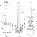
Figure 3A is a side elevational view of the main components provided in a possible embodiment of the treatment system according to the present invention, based on bearings; -
Figure 3B is a cross-sectional view ofFigure 3A ; -
Figure 3C is an ordered exploded view of the elements shown inFigure 3A ; -
Figure 4 is an ordered exploded view of the chamber provided in an embodiment of the treatment system according to the present invention; -
Figure 5 is an ordered exploded view of the cover of the chamber, provided in an embodiment of the treatment system according to the present invention; -
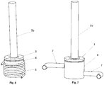
Figures 6 and 7 are perspective views illustrating additional elements of the treatment system in two possible embodiments of the treatment system according to the present invention; and -
Figure 8 is a side elevational view of a complete embodiment of the treatment system according to the present invention. -
- (1) Fluid;
- (2) Bearing;
- (2a) Rolling element;
- (2b) Moving ring;
- (2c) Fixed ring;
- (2d) Cage;
- (3) Cover;
- (3a) Cover body;
- (3b) Retainer;
- (3c) O-ring;
- (4) Chamber;
- (4a) Chamber body;
- (4b) Sleeve;
- (4c) Washer;
- (4d) Bore;
- (4e) Window for radiation;
- (5) Motor means;
- (5a) Motor;
- (5b) Shaft
- (5c) Protuberance of the shaft
- (5d) Coupling for coupling the motor to the shaft;
- (5e) Fixing element of the motor;
- (6) Coil;
- (7) Conduits for the entry/exit of material in a fluid state;
- (8) Tensioning means;
- (8a) Fixed base;
- (8b) Moving platform;
- (8c) Tightening devices;
- (8d) Reducers;
- (8e) Actuating device;
- (8f) Cardan joint;
- (8g) Guides for the moving platform;
- (9a) Load cell;
- (9b) Thermocouple;
- (A) Section line;
- (h1, h2) Thicknesses of the films of material in a fluid state;
- (p) Pressure;
- (v) Relative velocity between the elements of the kinematic pair;
- (w) Angular velocity.
- Throughout the present invention, as well as in the figures, the elements with equal or similar functions will be designated with the same numerical references.
-
Figure 1 shows anaxial bearing 2 for use in an embodiment of a treatment system according to the present invention. - Said
bearing 2 is supported on a fixedbase 8a and comprises rollingelements 2a which, in this particular case, are steel spheres, arranged between a movingring 2b and a fixedring 2c. To assure the separation between thedifferent rolling elements 2a, thebearing 2 is furthermore equipped with acage 2d. This figure also schematically illustrates how, in a treatment system according to the invention, an angular velocity w is imparted on the movingring 2b and a contact pressure p is exerted on the movingring 2b which pushes said ring against the fixedring 2c. -
Figure 2 schematically shows the upper kinematic pairs present in thebearing 2 which, within a treatment system according to the present invention, is placed in contact with a material in afluid state 1 which can contain suspended particles intended for being mixed with said fluid. - This specific case, the mechanical elements are the rolling
elements 2a, the movingring 2b, and the fixedring 2c. In fact, there are two upper kinematic pairs for each rollingelement 2a present in the bearing 2: a first kinematic pair formed by the movingring 2b and the rollingelement 2a and a second kinematic pair formed by the rollingelement 2a and the fixedring 2c. - If the relative velocity v existing between the elements of the kinematic pairs and the contact pressure p to which the mechanical elements are subjected are suitable, a first film of
fluid material 1, with a width h1 is formed between the elements of the first kinematic pair and a second film of fluid material, with a width h2, is formed between the elements of the second kinematic pair. - As will be obvious for one skilled in the art, in those cases in which the system for the treatment of materials according to the present invention is used for mixing a material in a
fluid state 1 with suspended particles, the mixture of the material in a fluid state and the particles (and not only the material in a fluid state) will give rise to the first and second films, of widths h1 and h2, mentioned in the preceding paragraph. -
Figures 3A, 3B, and 3C show the main components provided in a treatment system according to the present invention.Figure 3A is a side elevational view, whereasFigure 3C is an ordered exploded view thereof.Figure 3B is in turn a cross-sectional view along line A. - A
chamber 4 housing therein, according to this particular embodiment of the treatment system of the invention, twoaxial bearings 2, each of which is equipped with rollingelements 2a, a movingring 2b, and a fixedring 2c, can be seen in saidFigures 3A - 3C . - The
chamber 4 likewise houses the material in afluid state 1. Obviously, in those cases in which the system for the treatment of materials according to the present invention is used for mixing a material in afluid state 1 with suspended particles, thechamber 4 will house the mixture formed by the material in a fluid state and the suspended particles intended for being mixed with the material in a fluid state. Furthermore, saidcover 4 comprises abody 4a, and asleeve 4b andwasher 4c allowing the radial fixing of theaxial bearings 2. - Furthermore, the
chamber 4 is equipped with acover 3 subjected to a pressure p, exerted by pressure means (not seen inFigures 3A-3C ). Saidcover 3 comprises abody 3a equipped with a through hole allowing the passage of a shaft 5b. Saidshaft 5b is part of the motor means 5 and is fitted with the movingrings 2b of each bearing, such that the angular velocity w generated by the motor means 5 is transmitted without friction to the movingrings 2b of eachbearing 2. - In this particular embodiment of the invention, the
shaft 5b is equipped with aprotuberance 5c which maximises contact between saidshaft 5b and the movingrings 2b so as to prevent relative movement, and therefore friction, between same. - The
cover 3 is subjected to the pressure p generated by tensioning means (not seen inFigures 3A - 3C ). Said pressure p is transmitted to the mechanical elements of thebearings 2 through thebody 3a of thecover 3. Moreover, in this particular embodiment of the invention, thecover 3 is also equipped with aretainer 3b and an O-ring 3c which prevent the material in a fluid state 1 (or, as the case may be, the mixture formed by the material in afluid state 1 and the suspended particles) from being able to seep out of thechamber 4 through the through hole present in thebody 3a of thecover 3. Theretainer 3b and the O-ring 3c also prevent the entry or exit of air or other gases with respect to the inside of thechamber 4. -
Figure 4 shows an ordered exploded view of achamber 4 for use in a treatment system according to the present invention. In this particular embodiment of the invention, in addition to thebody 4a, thesleeve 4b, and thewasher 4c, thechamber 4 is also equipped with abore 4d for the controlled entry and/or exit of gas, as well as awindow 4e, allowing the access of electromagnetic or acoustic radiation, for example and in a non-limiting manner, ultrasound, to the inside of the chamber. - In those cases in which the system for the treatment of materials according to the present invention is used for mixing a material in a
fluid state 1 with the suspended particles, the electromagnetic and/or acoustic radiations mentioned in the preceding paragraph are normally used to improve the dispersion of the particles in the fluid material and if the particles are nanoparticles, to furthermore improve the adhesion between said nanoparticles and thefluid material 1. -
Figure 5 shows an ordered exploded view of thecover 3 described inFigures 3A to 3C . As seen above, saidcover 3 comprises thebody 3a, theretainer 3b, and the O-ring 3c. -
Figure 6 shows a particular embodiment of a treatment system according to the present invention which further comprises acoil 6, in addition to other components already explained in relation to other preceding figures. Said coil allows controlling the temperature of thefluid material 1, or as the case maybe, of the mixture formed by thefluid material 1 and the suspended particles. - Likewise,
Figure 7 shows a particular embodiment of a treatment system according to the present invention which further comprisesconduits 7 allowing the entry and/or exit of thefluid material 1, or as the case maybe, of the mixture formed by thefluid material 1 and the suspended particles, with respect to the inside of the chamber, in addition to other components already explained in relation to other preceding figures. - Lastly,
Figure 8 shows a particular embodiment of a complete treatment system according to the present invention. In the particular embodiment of the invention shown in this figure, the motor means 5 comprise amotor 5a connected to theshaft 5b through acoupling 5d. Therefore, when themotor 5a is actuated, the resulting driving torque is transmitted to theshaft 5b, such that saidshaft 5b is capable of rotating at an angular velocity w (schematically illustrated inFigures 1 and3A ). - Furthermore, in this particular embodiment of the invention, the
chamber 4 containing thefluid material 1, or as the case maybe, the mixture offluid material 1 and suspended particles, is arranged on the fixedbase 8a. Themotor 5a is fixed to said fixedbase 8a by means of a fixingelement 5e. - Moreover, in this particular embodiment of the invention, the pressure means 8 comprise, in addition to the fixed
base 8a, a movingplatform 8b which is capable of moving as a result of the action of anactuating device 8e (in this embodiment, a motor) which causes the rotation of tightening devices 8c which, in this embodiment of the invention, are screws coupled to threaded through portions provided in the movingplatform 8b. As a result of this movement, the movingplatform 8b can exert pressure on thecover 3 of thechamber 4, and said pressure is in turn transmitted by contact to the mechanical elements. - Optionally,
speed reducers 8d can be arranged between the screws 8c and the actuating device 8e. Saidreducers 8d allow amplifying the force which the screw can exert for one same pair of theactuating device 8e. Preferably, there are also provided a cardan joint 8f which allows equalising the rotating speed of thereducers 8d and guides 8g which allow the movingplatform 8b to move parallel to the fixedbase 8a. - There are also provided in this embodiment of the invention at least one
load cell 9a intended for measuring the compressive force applied on thecover 3 by the tensioning means and at least onethermocouple 9b intended for measuring the temperature of thefluid material 1, or as the case maybe, of the mixture formed by thefluid material 1 and the suspended particles intended for being mixed with saidfluid material 1. - The present invention is in no way limited to the embodiments herein disclosed. For a person skilled in the art, other possible different embodiments of this invention will be evident in light of the present description. As a result, the scope of protection of the present invention is exclusively defined by the claims that follow.
Claims (14)
- A system for the treatment of materials, selected from between materials in a fluid state (1) and particles suspended in a fluid material (1), comprising:- at least one upper kinematic pair equipped with two mechanical elements (2a, 2b; 2a, 2c), said kinematic pair being in contact with a material in a fluid state (1) or in contact with particles suspended in a fluid material (1);- motor means (5) to generate a pre-set relative velocity (v) between the mechanical elements (2a, 2b; 2a, 2c) of said kinematic pair; and- tensioning means (8) to subject said kinematic pair to a pre-set contact pressure (p);characterised in that the upper kinematic pair is formed by at least one bearing (2) equipped with rolling elements (2a) arranged between a moving ring (2b) and a fixed ring (2c).
- The treatment system according to claim 1, characterised in that the bearing (2) comprises a cage (2d) for separating the rolling elements (2a).
- The treatment system according to any of the preceding claims, characterised in that it comprises at least one upper kinematic pair formed by a gear, a cam-follower mechanism, a chain-sprocket mechanism, a chain transmission, a belt transmission, a cable transmission, a pin-on-disk tribometer, or a ball-on-disk tribometer.
- The treatment system according to any of the preceding claims, characterised in that the upper kinematic pairs are housed in a chamber (4) hermetically closed by a cover (3).
- The treatment system according to claim 4, characterised in that the closed chamber (4) is equipped with conduits (7) for the entry and/or exit of materials in a fluid state (1).
- The treatment system according to claim 4, characterised in that the chamber (4) is equipped with at least one bore (4d) for the controlled entry and/or exit of gas.
- The treatment system according to claim 4, characterised in that it is furthermore equipped with a coil (6) through which a heat exchange fluid circulates.
- The treatment system according to claim 4, characterised in that it is furthermore equipped with at least one window allowing the access of electromagnetic or acoustic radiation to the inside of the chamber.
- The treatment system according to claim 4, characterised in that the motor means (5) comprise a motor (5a) connected to a transmission shaft (5b), such that said motor (5a) is capable of transmitting an angular velocity (w) to said transmission shaft (5b), said shaft (5b) accessing the inside of the chamber (4) through an opening provided in the cover body (3a) of the cover (3), such that the shaft (5b) can transmit said angular velocity (w) to one of the elements (2b) of the kinematic pair.
- The treatment system according to claim 9, characterised in that the cover (3) further comprises a retainer (3b) and an O-ring (3c).
- The treatment system according to claim 4, characterised in that the chamber (4) comprises a chamber body (4a) for housing the material in a fluid state (1), and a sleeve (4b) and a washer (4c) for fixing the kinematic pairs.
- The treatment system according to claim 4, characterised in that the tensioning means (8) comprise a fixed base (8a) on which the chamber (4) is arranged and a moving platform (8b) movable by means of tightening devices (8c) so as to exert pressure on the cover (3) of the chamber (4), said tightening devices (8c) being controlled by an actuating device (8e).
- The treatment system according to claim 12, characterised in that the tensioning means (8) are furthermore equipped with:- speed reducers (8d) arranged between the tightening devices (8c) and the actuating device (8e);- a cardan joint (8f), and- guides (8g) for guiding the movement of the moving platform (8b).
- The treatment system according to any of the preceding claims, characterised in that it is furthermore equipped with vibrating means to subject the kinematic pair to a vibratory movement.
Applications Claiming Priority (2)
| Application Number | Priority Date | Filing Date | Title |
|---|---|---|---|
| ES201831123A ES2722499B2 (en) | 2018-11-20 | 2018-11-20 | MATERIALS TREATMENT METHOD AND SYSTEM |
| PCT/ES2019/070789 WO2020104721A1 (en) | 2018-11-20 | 2019-11-19 | Method and system for the treatment of materials |
Publications (3)
| Publication Number | Publication Date |
|---|---|
| EP3885033A1 true EP3885033A1 (en) | 2021-09-29 |
| EP3885033A4 EP3885033A4 (en) | 2022-05-04 |
| EP3885033B1 EP3885033B1 (en) | 2024-03-27 |
Family
ID=67513760
Family Applications (1)
| Application Number | Title | Priority Date | Filing Date |
|---|---|---|---|
| EP19888053.6A Active EP3885033B1 (en) | 2018-11-20 | 2019-11-19 | System for the treatment of materials |
Country Status (6)
| Country | Link |
|---|---|
| US (1) | US12233387B2 (en) |
| EP (1) | EP3885033B1 (en) |
| JP (1) | JP7437785B2 (en) |
| CA (1) | CA3120467A1 (en) |
| ES (1) | ES2722499B2 (en) |
| WO (1) | WO2020104721A1 (en) |
Families Citing this family (3)
| Publication number | Priority date | Publication date | Assignee | Title |
|---|---|---|---|---|
| WO2023245226A1 (en) * | 2022-06-23 | 2023-12-28 | White Graphene Limited | Shear milling apparatus and method |
| CN115301180B (en) * | 2022-06-29 | 2023-12-26 | 南通恒兆节能科技有限公司 | Mixing tower for refrigerant production |
| CN116808988B (en) * | 2023-04-21 | 2025-09-12 | 浙江工业职业技术学院 | A microemulsion polymerization mixing drum |
Family Cites Families (24)
| Publication number | Priority date | Publication date | Assignee | Title |
|---|---|---|---|---|
| US537947A (en) * | 1895-04-23 | tornaghi | ||
| US646507A (en) * | 1899-10-11 | 1900-04-03 | Thomas J Sturtevant | Pulverizing-mill. |
| US1401716A (en) * | 1921-02-12 | 1921-12-27 | Mccrae George | Pulverizer or grinding-machine |
| GB235227A (en) * | 1924-06-07 | 1925-08-06 | Siemens Ag | Improvements in and relating to the production of colloidal solutions |
| DE660721C (en) * | 1936-05-26 | 1938-06-01 | Hermann Plauson | High-speed reaming machine |
| US2115314A (en) * | 1936-09-03 | 1938-04-26 | Mcerlean Wallace Ferguso James | Ore mill |
| US2204140A (en) * | 1937-09-28 | 1940-06-11 | Harold W Langbein | Mill |
| US2432610A (en) * | 1944-09-19 | 1947-12-16 | John H Dryer | Self-classifying ball mill |
| BE640416A (en) * | 1962-11-27 | |||
| US3375982A (en) * | 1966-06-17 | 1968-04-02 | Richard S. Lease | Method and system for reducing coal losses at pyrite traps of a coal pulverizer |
| CH480088A (en) * | 1969-02-12 | 1969-10-31 | Centrans Gmbh | Device for mixing and / or grinding, suspending, disintegrating, emulsifying and homogenizing liquid or liquid / solid mixtures |
| GB1345531A (en) * | 1970-05-06 | 1974-01-30 | Rubber Plastics Research Ass O | Mixing devices |
| SU1095977A1 (en) * | 1982-06-11 | 1984-06-07 | Горьковский Государственный Химико-Фармацевтический Завод | Apparatus for dispersion and homogenization of disperse system |
| SU1449155A1 (en) * | 1984-11-22 | 1989-01-07 | Украинский заочный политехнический институт им.И.З.Соколова | Disperser for making varnish-and-paint suspensions |
| CA2079997A1 (en) * | 1990-04-06 | 1991-10-07 | Thomas W. Winstead | Dynamic mixing system and method for producing thermoplastic materials |
| US20060106147A1 (en) * | 2004-11-12 | 2006-05-18 | Fasulo Paula D | Method for making nanocomposite materials |
| GB2449681B (en) * | 2007-05-31 | 2009-11-11 | Southwestern Corp Ltd | Adapting a grinding mill to introduce a grinding element |
| DE502007005912D1 (en) * | 2007-12-27 | 2011-01-20 | Peters Claudius Tech Gmbh | Apparatus and method for monitoring the grinding ball movement in a ball mill |
| US20100009165A1 (en) * | 2008-07-10 | 2010-01-14 | Zyvex Performance Materials, Llc | Multifunctional Nanomaterial-Containing Composites and Methods for the Production Thereof |
| WO2011024108A2 (en) * | 2009-08-25 | 2011-03-03 | Tjaart Johannes Barnard | Diminution of particulate material |
| US20120292578A1 (en) * | 2009-11-18 | 2012-11-22 | Alexander Bacher | METHOD FOR PRODUCING COMPOSITE MATERIALS BASED ON POLYMERS AND CARBON NANOTUBES (CNTs), COMPOSITE MATERIALS PRODUCED IN THIS WAY AND USE THEREOF |
| KR102031016B1 (en) * | 2012-01-25 | 2019-10-11 | 엠. 테크닉 가부시키가이샤 | Manufacturing processes for garnet precursor microparticles and microparticles of garnet structure |
| KR102698136B1 (en) * | 2014-12-15 | 2024-08-23 | 엠. 테크닉 가부시키가이샤 | Method for producing organic material microparticles |
| CN204338244U (en) * | 2014-12-18 | 2015-05-20 | 李广勋 | Combined type orderly multi-pass internal classification screening vertical ball mill |
-
2018
- 2018-11-20 ES ES201831123A patent/ES2722499B2/en active Active
-
2019
- 2019-11-19 CA CA3120467A patent/CA3120467A1/en active Pending
- 2019-11-19 JP JP2021527929A patent/JP7437785B2/en active Active
- 2019-11-19 EP EP19888053.6A patent/EP3885033B1/en active Active
- 2019-11-19 US US17/295,157 patent/US12233387B2/en active Active
- 2019-11-19 WO PCT/ES2019/070789 patent/WO2020104721A1/en not_active Ceased
Also Published As
| Publication number | Publication date |
|---|---|
| JP2022514190A (en) | 2022-02-10 |
| ES2722499A1 (en) | 2019-08-12 |
| EP3885033B1 (en) | 2024-03-27 |
| EP3885033A4 (en) | 2022-05-04 |
| ES2722499B2 (en) | 2021-06-15 |
| US12233387B2 (en) | 2025-02-25 |
| CA3120467A1 (en) | 2020-05-28 |
| US20220008875A1 (en) | 2022-01-13 |
| JP7437785B2 (en) | 2024-02-26 |
| WO2020104721A1 (en) | 2020-05-28 |
Similar Documents
| Publication | Publication Date | Title |
|---|---|---|
| US12233387B2 (en) | Method and system for the treatment of materials | |
| Malaki et al. | Mechanotribological aspects of MXene‐reinforced nanocomposites | |
| Amirbeygi et al. | Reinforcing effects of aminosilane‐functionalized graphene on the tribological and mechanical behaviors of epoxy nanocomposites | |
| Li et al. | Surface wettability effect on aqueous lubrication: Van der Waals and hydration force competition induced adhesive friction | |
| Upadhyay et al. | Effect of humidity on the synergy of friction and wear properties in ternary epoxy-graphene-MoS2 composites | |
| Friedrich et al. | Effects of various fillers on the sliding wear of polymer composites | |
| Friedrich et al. | Current and future applications of polymer composites in the field of tribology | |
| Mu et al. | Self‐lubricating polytetrafluoroethylene/polyimide blends reinforced with zinc oxide nanoparticles | |
| Mu et al. | Tribological behaviors of polyurethane composites containing self‐lubricating microcapsules and reinforced by short carbon fibers | |
| Abd-Elnaiem et al. | Mechanical characteristics and thermal stability of hybrid epoxy and acrylic polymer coating/nanoclay of various thicknesses | |
| Naidu et al. | Effect of g‐C3N4 nanofiller as filler on mechanical properties of multidirectional glass fiber epoxy hybrid composites | |
| Sun et al. | Mechanical and tribological properties of polyoxymethylene modified with nanoparticles and solid lubricants | |
| Ren et al. | Influence of lubricant filling on the dry sliding wear behaviors of hybrid PTFE/Nomex fabric composite | |
| Alharbi | Wear and mechanical contact behavior of polymer gears | |
| Ren et al. | WS2-filled hybrid PTFE/Nomex fabric composites with improved antiwear property | |
| Wang et al. | Modification effects of short carbon fibers on mechanical properties and fretting wear behavior of UHMWPE composites | |
| Poveda et al. | Carbon-nanofiber-reinforced syntactic foams: compressive properties and strain rate sensitivity | |
| Goriparthi et al. | Performance evaluation of composite gears composed of POM, CNTs, and PTFE | |
| Adarmanabadi et al. | Effect of nano clay, nano-graphene oxide and carbon nanotubes on the mechanical and tribological properties of crosslinked epoxy nanocomposite | |
| Amrishraj et al. | Development of wear mechanism maps for acrylonitrile butadiene styrene hybrid composites reinforced with nano zirconia and PTFE under dry sliding condition | |
| Tiwari et al. | Stiffness enhancement of polymer nanocomposites via graphene nanoplatelet orientation | |
| Zhang et al. | Enhancement on the tribological properties of poly (phthalazinone ether sulfone ketone) by carbon nanotube‐supported graphitic carbon nitride hybrid | |
| Aly et al. | Enhancement in mechanical properties of polystyrene filled with carbon nano-particulates (CNPS) | |
| He et al. | Thermal conductivity and tribological properties of POM‐Cu composites | |
| Rajamani et al. | Experimental studies on the performance of graphene oxide based hybrid nanopolymers for bearing applications |
Legal Events
| Date | Code | Title | Description |
|---|---|---|---|
| STAA | Information on the status of an ep patent application or granted ep patent |
Free format text: STATUS: THE INTERNATIONAL PUBLICATION HAS BEEN MADE |
|
| PUAI | Public reference made under article 153(3) epc to a published international application that has entered the european phase |
Free format text: ORIGINAL CODE: 0009012 |
|
| STAA | Information on the status of an ep patent application or granted ep patent |
Free format text: STATUS: REQUEST FOR EXAMINATION WAS MADE |
|
| 17P | Request for examination filed |
Effective date: 20210525 |
|
| AK | Designated contracting states |
Kind code of ref document: A1 Designated state(s): AL AT BE BG CH CY CZ DE DK EE ES FI FR GB GR HR HU IE IS IT LI LT LU LV MC MK MT NL NO PL PT RO RS SE SI SK SM TR |
|
| RIC1 | Information provided on ipc code assigned before grant |
Ipc: B02C 15/12 20060101ALI20211130BHEP Ipc: B01F 7/00 20060101ALI20211130BHEP Ipc: B01F 3/12 20060101AFI20211130BHEP |
|
| DAV | Request for validation of the european patent (deleted) | ||
| DAX | Request for extension of the european patent (deleted) | ||
| REG | Reference to a national code |
Ref country code: DE Ref legal event code: R079 Free format text: PREVIOUS MAIN CLASS: B01F0005060000 Ipc: B01F0023530000 Ref country code: DE Ref legal event code: R079 Ref document number: 602019049220 Country of ref document: DE Free format text: PREVIOUS MAIN CLASS: B01F0005060000 Ipc: B01F0023530000 |
|
| A4 | Supplementary search report drawn up and despatched |
Effective date: 20220404 |
|
| RIC1 | Information provided on ipc code assigned before grant |
Ipc: B02C 15/12 20060101ALI20220328BHEP Ipc: B01F 27/27 20220101ALI20220328BHEP Ipc: B01F 23/53 20220101AFI20220328BHEP |
|
| GRAP | Despatch of communication of intention to grant a patent |
Free format text: ORIGINAL CODE: EPIDOSNIGR1 |
|
| STAA | Information on the status of an ep patent application or granted ep patent |
Free format text: STATUS: GRANT OF PATENT IS INTENDED |
|
| INTG | Intention to grant announced |
Effective date: 20231108 |
|
| GRAS | Grant fee paid |
Free format text: ORIGINAL CODE: EPIDOSNIGR3 |
|
| GRAA | (expected) grant |
Free format text: ORIGINAL CODE: 0009210 |
|
| STAA | Information on the status of an ep patent application or granted ep patent |
Free format text: STATUS: THE PATENT HAS BEEN GRANTED |
|
| AK | Designated contracting states |
Kind code of ref document: B1 Designated state(s): AL AT BE BG CH CY CZ DE DK EE ES FI FR GB GR HR HU IE IS IT LI LT LU LV MC MK MT NL NO PL PT RO RS SE SI SK SM TR |
|
| REG | Reference to a national code |
Ref country code: GB Ref legal event code: FG4D |
|
| REG | Reference to a national code |
Ref country code: CH Ref legal event code: EP |
|
| REG | Reference to a national code |
Ref country code: DE Ref legal event code: R096 Ref document number: 602019049220 Country of ref document: DE |
|
| REG | Reference to a national code |
Ref country code: IE Ref legal event code: FG4D |
|
| PG25 | Lapsed in a contracting state [announced via postgrant information from national office to epo] |
Ref country code: LT Free format text: LAPSE BECAUSE OF FAILURE TO SUBMIT A TRANSLATION OF THE DESCRIPTION OR TO PAY THE FEE WITHIN THE PRESCRIBED TIME-LIMIT Effective date: 20240327 |
|
| REG | Reference to a national code |
Ref country code: LT Ref legal event code: MG9D |
|
| PG25 | Lapsed in a contracting state [announced via postgrant information from national office to epo] |
Ref country code: GR Free format text: LAPSE BECAUSE OF FAILURE TO SUBMIT A TRANSLATION OF THE DESCRIPTION OR TO PAY THE FEE WITHIN THE PRESCRIBED TIME-LIMIT Effective date: 20240628 |
|
| PG25 | Lapsed in a contracting state [announced via postgrant information from national office to epo] |
Ref country code: HR Free format text: LAPSE BECAUSE OF FAILURE TO SUBMIT A TRANSLATION OF THE DESCRIPTION OR TO PAY THE FEE WITHIN THE PRESCRIBED TIME-LIMIT Effective date: 20240327 Ref country code: RS Free format text: LAPSE BECAUSE OF FAILURE TO SUBMIT A TRANSLATION OF THE DESCRIPTION OR TO PAY THE FEE WITHIN THE PRESCRIBED TIME-LIMIT Effective date: 20240627 |
|
| PG25 | Lapsed in a contracting state [announced via postgrant information from national office to epo] |
Ref country code: RS Free format text: LAPSE BECAUSE OF FAILURE TO SUBMIT A TRANSLATION OF THE DESCRIPTION OR TO PAY THE FEE WITHIN THE PRESCRIBED TIME-LIMIT Effective date: 20240627 Ref country code: NO Free format text: LAPSE BECAUSE OF FAILURE TO SUBMIT A TRANSLATION OF THE DESCRIPTION OR TO PAY THE FEE WITHIN THE PRESCRIBED TIME-LIMIT Effective date: 20240627 Ref country code: LT Free format text: LAPSE BECAUSE OF FAILURE TO SUBMIT A TRANSLATION OF THE DESCRIPTION OR TO PAY THE FEE WITHIN THE PRESCRIBED TIME-LIMIT Effective date: 20240327 Ref country code: HR Free format text: LAPSE BECAUSE OF FAILURE TO SUBMIT A TRANSLATION OF THE DESCRIPTION OR TO PAY THE FEE WITHIN THE PRESCRIBED TIME-LIMIT Effective date: 20240327 Ref country code: GR Free format text: LAPSE BECAUSE OF FAILURE TO SUBMIT A TRANSLATION OF THE DESCRIPTION OR TO PAY THE FEE WITHIN THE PRESCRIBED TIME-LIMIT Effective date: 20240628 Ref country code: FI Free format text: LAPSE BECAUSE OF FAILURE TO SUBMIT A TRANSLATION OF THE DESCRIPTION OR TO PAY THE FEE WITHIN THE PRESCRIBED TIME-LIMIT Effective date: 20240327 Ref country code: BG Free format text: LAPSE BECAUSE OF FAILURE TO SUBMIT A TRANSLATION OF THE DESCRIPTION OR TO PAY THE FEE WITHIN THE PRESCRIBED TIME-LIMIT Effective date: 20240327 |
|
| REG | Reference to a national code |
Ref country code: NL Ref legal event code: MP Effective date: 20240327 |
|
| PG25 | Lapsed in a contracting state [announced via postgrant information from national office to epo] |
Ref country code: SE Free format text: LAPSE BECAUSE OF FAILURE TO SUBMIT A TRANSLATION OF THE DESCRIPTION OR TO PAY THE FEE WITHIN THE PRESCRIBED TIME-LIMIT Effective date: 20240327 Ref country code: LV Free format text: LAPSE BECAUSE OF FAILURE TO SUBMIT A TRANSLATION OF THE DESCRIPTION OR TO PAY THE FEE WITHIN THE PRESCRIBED TIME-LIMIT Effective date: 20240327 |
|
| PG25 | Lapsed in a contracting state [announced via postgrant information from national office to epo] |
Ref country code: NL Free format text: LAPSE BECAUSE OF FAILURE TO SUBMIT A TRANSLATION OF THE DESCRIPTION OR TO PAY THE FEE WITHIN THE PRESCRIBED TIME-LIMIT Effective date: 20240327 |
|
| REG | Reference to a national code |
Ref country code: AT Ref legal event code: MK05 Ref document number: 1669391 Country of ref document: AT Kind code of ref document: T Effective date: 20240327 |
|
| PG25 | Lapsed in a contracting state [announced via postgrant information from national office to epo] |
Ref country code: NL Free format text: LAPSE BECAUSE OF FAILURE TO SUBMIT A TRANSLATION OF THE DESCRIPTION OR TO PAY THE FEE WITHIN THE PRESCRIBED TIME-LIMIT Effective date: 20240327 |
|
| PG25 | Lapsed in a contracting state [announced via postgrant information from national office to epo] |
Ref country code: IS Free format text: LAPSE BECAUSE OF FAILURE TO SUBMIT A TRANSLATION OF THE DESCRIPTION OR TO PAY THE FEE WITHIN THE PRESCRIBED TIME-LIMIT Effective date: 20240727 |
|
| PG25 | Lapsed in a contracting state [announced via postgrant information from national office to epo] |
Ref country code: PT Free format text: LAPSE BECAUSE OF FAILURE TO SUBMIT A TRANSLATION OF THE DESCRIPTION OR TO PAY THE FEE WITHIN THE PRESCRIBED TIME-LIMIT Effective date: 20240729 Ref country code: SM Free format text: LAPSE BECAUSE OF FAILURE TO SUBMIT A TRANSLATION OF THE DESCRIPTION OR TO PAY THE FEE WITHIN THE PRESCRIBED TIME-LIMIT Effective date: 20240327 |
|
| PG25 | Lapsed in a contracting state [announced via postgrant information from national office to epo] |
Ref country code: ES Free format text: LAPSE BECAUSE OF FAILURE TO SUBMIT A TRANSLATION OF THE DESCRIPTION OR TO PAY THE FEE WITHIN THE PRESCRIBED TIME-LIMIT Effective date: 20240327 |
|
| PG25 | Lapsed in a contracting state [announced via postgrant information from national office to epo] |
Ref country code: CZ Free format text: LAPSE BECAUSE OF FAILURE TO SUBMIT A TRANSLATION OF THE DESCRIPTION OR TO PAY THE FEE WITHIN THE PRESCRIBED TIME-LIMIT Effective date: 20240327 Ref country code: EE Free format text: LAPSE BECAUSE OF FAILURE TO SUBMIT A TRANSLATION OF THE DESCRIPTION OR TO PAY THE FEE WITHIN THE PRESCRIBED TIME-LIMIT Effective date: 20240327 |
|
| PG25 | Lapsed in a contracting state [announced via postgrant information from national office to epo] |
Ref country code: AT Free format text: LAPSE BECAUSE OF FAILURE TO SUBMIT A TRANSLATION OF THE DESCRIPTION OR TO PAY THE FEE WITHIN THE PRESCRIBED TIME-LIMIT Effective date: 20240327 |
|
| PG25 | Lapsed in a contracting state [announced via postgrant information from national office to epo] |
Ref country code: PL Free format text: LAPSE BECAUSE OF FAILURE TO SUBMIT A TRANSLATION OF THE DESCRIPTION OR TO PAY THE FEE WITHIN THE PRESCRIBED TIME-LIMIT Effective date: 20240327 |
|
| PG25 | Lapsed in a contracting state [announced via postgrant information from national office to epo] |
Ref country code: SK Free format text: LAPSE BECAUSE OF FAILURE TO SUBMIT A TRANSLATION OF THE DESCRIPTION OR TO PAY THE FEE WITHIN THE PRESCRIBED TIME-LIMIT Effective date: 20240327 |
|
| PG25 | Lapsed in a contracting state [announced via postgrant information from national office to epo] |
Ref country code: SM Free format text: LAPSE BECAUSE OF FAILURE TO SUBMIT A TRANSLATION OF THE DESCRIPTION OR TO PAY THE FEE WITHIN THE PRESCRIBED TIME-LIMIT Effective date: 20240327 Ref country code: SK Free format text: LAPSE BECAUSE OF FAILURE TO SUBMIT A TRANSLATION OF THE DESCRIPTION OR TO PAY THE FEE WITHIN THE PRESCRIBED TIME-LIMIT Effective date: 20240327 Ref country code: RO Free format text: LAPSE BECAUSE OF FAILURE TO SUBMIT A TRANSLATION OF THE DESCRIPTION OR TO PAY THE FEE WITHIN THE PRESCRIBED TIME-LIMIT Effective date: 20240327 Ref country code: PT Free format text: LAPSE BECAUSE OF FAILURE TO SUBMIT A TRANSLATION OF THE DESCRIPTION OR TO PAY THE FEE WITHIN THE PRESCRIBED TIME-LIMIT Effective date: 20240729 Ref country code: PL Free format text: LAPSE BECAUSE OF FAILURE TO SUBMIT A TRANSLATION OF THE DESCRIPTION OR TO PAY THE FEE WITHIN THE PRESCRIBED TIME-LIMIT Effective date: 20240327 Ref country code: IS Free format text: LAPSE BECAUSE OF FAILURE TO SUBMIT A TRANSLATION OF THE DESCRIPTION OR TO PAY THE FEE WITHIN THE PRESCRIBED TIME-LIMIT Effective date: 20240727 Ref country code: ES Free format text: LAPSE BECAUSE OF FAILURE TO SUBMIT A TRANSLATION OF THE DESCRIPTION OR TO PAY THE FEE WITHIN THE PRESCRIBED TIME-LIMIT Effective date: 20240327 Ref country code: EE Free format text: LAPSE BECAUSE OF FAILURE TO SUBMIT A TRANSLATION OF THE DESCRIPTION OR TO PAY THE FEE WITHIN THE PRESCRIBED TIME-LIMIT Effective date: 20240327 Ref country code: CZ Free format text: LAPSE BECAUSE OF FAILURE TO SUBMIT A TRANSLATION OF THE DESCRIPTION OR TO PAY THE FEE WITHIN THE PRESCRIBED TIME-LIMIT Effective date: 20240327 Ref country code: AT Free format text: LAPSE BECAUSE OF FAILURE TO SUBMIT A TRANSLATION OF THE DESCRIPTION OR TO PAY THE FEE WITHIN THE PRESCRIBED TIME-LIMIT Effective date: 20240327 |
|
| REG | Reference to a national code |
Ref country code: DE Ref legal event code: R097 Ref document number: 602019049220 Country of ref document: DE |
|
| PG25 | Lapsed in a contracting state [announced via postgrant information from national office to epo] |
Ref country code: DK Free format text: LAPSE BECAUSE OF FAILURE TO SUBMIT A TRANSLATION OF THE DESCRIPTION OR TO PAY THE FEE WITHIN THE PRESCRIBED TIME-LIMIT Effective date: 20240327 |
|
| PG25 | Lapsed in a contracting state [announced via postgrant information from national office to epo] |
Ref country code: DK Free format text: LAPSE BECAUSE OF FAILURE TO SUBMIT A TRANSLATION OF THE DESCRIPTION OR TO PAY THE FEE WITHIN THE PRESCRIBED TIME-LIMIT Effective date: 20240327 |
|
| PLBE | No opposition filed within time limit |
Free format text: ORIGINAL CODE: 0009261 |
|
| STAA | Information on the status of an ep patent application or granted ep patent |
Free format text: STATUS: NO OPPOSITION FILED WITHIN TIME LIMIT |
|
| 26N | No opposition filed |
Effective date: 20250103 |
|
| PG25 | Lapsed in a contracting state [announced via postgrant information from national office to epo] |
Ref country code: SI Free format text: LAPSE BECAUSE OF FAILURE TO SUBMIT A TRANSLATION OF THE DESCRIPTION OR TO PAY THE FEE WITHIN THE PRESCRIBED TIME-LIMIT Effective date: 20240327 |
|
| REG | Reference to a national code |
Ref country code: CH Ref legal event code: PL |
|
| PG25 | Lapsed in a contracting state [announced via postgrant information from national office to epo] |
Ref country code: MC Free format text: LAPSE BECAUSE OF FAILURE TO SUBMIT A TRANSLATION OF THE DESCRIPTION OR TO PAY THE FEE WITHIN THE PRESCRIBED TIME-LIMIT Effective date: 20240327 |
|
| PG25 | Lapsed in a contracting state [announced via postgrant information from national office to epo] |
Ref country code: LU Free format text: LAPSE BECAUSE OF NON-PAYMENT OF DUE FEES Effective date: 20241119 |
|
| REG | Reference to a national code |
Ref country code: CH Ref legal event code: PL |
|
| GBPC | Gb: european patent ceased through non-payment of renewal fee |
Effective date: 20241119 |
|
| PG25 | Lapsed in a contracting state [announced via postgrant information from national office to epo] |
Ref country code: CH Free format text: LAPSE BECAUSE OF NON-PAYMENT OF DUE FEES Effective date: 20241130 |
|
| REG | Reference to a national code |
Ref country code: BE Ref legal event code: MM Effective date: 20241130 |
|
| PG25 | Lapsed in a contracting state [announced via postgrant information from national office to epo] |
Ref country code: GB Free format text: LAPSE BECAUSE OF NON-PAYMENT OF DUE FEES Effective date: 20241119 Ref country code: BE Free format text: LAPSE BECAUSE OF NON-PAYMENT OF DUE FEES Effective date: 20241130 |
|
| PG25 | Lapsed in a contracting state [announced via postgrant information from national office to epo] |
Ref country code: IE Free format text: LAPSE BECAUSE OF NON-PAYMENT OF DUE FEES Effective date: 20241119 |
|
| PGFP | Annual fee paid to national office [announced via postgrant information from national office to epo] |
Ref country code: DE Payment date: 20251119 Year of fee payment: 7 |
|
| PGFP | Annual fee paid to national office [announced via postgrant information from national office to epo] |
Ref country code: IT Payment date: 20251125 Year of fee payment: 7 |
|
| PGFP | Annual fee paid to national office [announced via postgrant information from national office to epo] |
Ref country code: FR Payment date: 20251126 Year of fee payment: 7 |
|
| PG25 | Lapsed in a contracting state [announced via postgrant information from national office to epo] |
Ref country code: HU Free format text: LAPSE BECAUSE OF FAILURE TO SUBMIT A TRANSLATION OF THE DESCRIPTION OR TO PAY THE FEE WITHIN THE PRESCRIBED TIME-LIMIT; INVALID AB INITIO Effective date: 20191119 |
|
| PG25 | Lapsed in a contracting state [announced via postgrant information from national office to epo] |
Ref country code: CY Free format text: LAPSE BECAUSE OF FAILURE TO SUBMIT A TRANSLATION OF THE DESCRIPTION OR TO PAY THE FEE WITHIN THE PRESCRIBED TIME-LIMIT; INVALID AB INITIO Effective date: 20191119 |