EP3884876A2 - Anchor delivery systems - Google Patents
Anchor delivery systems Download PDFInfo
- Publication number
- EP3884876A2 EP3884876A2 EP21159774.5A EP21159774A EP3884876A2 EP 3884876 A2 EP3884876 A2 EP 3884876A2 EP 21159774 A EP21159774 A EP 21159774A EP 3884876 A2 EP3884876 A2 EP 3884876A2
- Authority
- EP
- European Patent Office
- Prior art keywords
- axially
- anchor
- sleeve body
- delivery system
- tip
- Prior art date
- Legal status (The legal status is an assumption and is not a legal conclusion. Google has not performed a legal analysis and makes no representation as to the accuracy of the status listed.)
- Granted
Links
Images






Classifications
-
- A—HUMAN NECESSITIES
- A61—MEDICAL OR VETERINARY SCIENCE; HYGIENE
- A61B—DIAGNOSIS; SURGERY; IDENTIFICATION
- A61B17/00—Surgical instruments, devices or methods
- A61B17/04—Surgical instruments, devices or methods for suturing wounds; Holders or packages for needles or suture materials
- A61B17/0401—Suture anchors, buttons or pledgets, i.e. means for attaching sutures to bone, cartilage or soft tissue; Instruments for applying or removing suture anchors
-
- A—HUMAN NECESSITIES
- A61—MEDICAL OR VETERINARY SCIENCE; HYGIENE
- A61B—DIAGNOSIS; SURGERY; IDENTIFICATION
- A61B17/00—Surgical instruments, devices or methods
- A61B17/04—Surgical instruments, devices or methods for suturing wounds; Holders or packages for needles or suture materials
- A61B17/0469—Suturing instruments for use in minimally invasive surgery, e.g. endoscopic surgery
-
- A—HUMAN NECESSITIES
- A61—MEDICAL OR VETERINARY SCIENCE; HYGIENE
- A61B—DIAGNOSIS; SURGERY; IDENTIFICATION
- A61B17/00—Surgical instruments, devices or methods
- A61B17/04—Surgical instruments, devices or methods for suturing wounds; Holders or packages for needles or suture materials
- A61B17/0491—Sewing machines for surgery
-
- A—HUMAN NECESSITIES
- A61—MEDICAL OR VETERINARY SCIENCE; HYGIENE
- A61B—DIAGNOSIS; SURGERY; IDENTIFICATION
- A61B17/00—Surgical instruments, devices or methods
- A61B17/16—Instruments for performing osteoclasis; Drills or chisels for bones; Trepans
- A61B17/1655—Instruments for performing osteoclasis; Drills or chisels for bones; Trepans for tapping
-
- A—HUMAN NECESSITIES
- A61—MEDICAL OR VETERINARY SCIENCE; HYGIENE
- A61B—DIAGNOSIS; SURGERY; IDENTIFICATION
- A61B17/00—Surgical instruments, devices or methods
- A61B17/56—Surgical instruments or methods for treatment of bones or joints; Devices specially adapted therefor
- A61B17/58—Surgical instruments or methods for treatment of bones or joints; Devices specially adapted therefor for osteosynthesis, e.g. bone plates, screws or setting implements
- A61B17/68—Internal fixation devices, including fasteners and spinal fixators, even if a part thereof projects from the skin
- A61B17/84—Fasteners therefor or fasteners being internal fixation devices
- A61B17/86—Pins or screws or threaded wires; nuts therefor
- A61B17/8645—Headless screws, e.g. ligament interference screws
-
- A—HUMAN NECESSITIES
- A61—MEDICAL OR VETERINARY SCIENCE; HYGIENE
- A61B—DIAGNOSIS; SURGERY; IDENTIFICATION
- A61B17/00—Surgical instruments, devices or methods
- A61B17/56—Surgical instruments or methods for treatment of bones or joints; Devices specially adapted therefor
- A61B17/58—Surgical instruments or methods for treatment of bones or joints; Devices specially adapted therefor for osteosynthesis, e.g. bone plates, screws or setting implements
- A61B17/88—Osteosynthesis instruments; Methods or means for implanting or extracting internal or external fixation devices
- A61B17/8875—Screwdrivers, spanners or wrenches
- A61B17/8877—Screwdrivers, spanners or wrenches characterised by the cross-section of the driver bit
- A61B17/888—Screwdrivers, spanners or wrenches characterised by the cross-section of the driver bit the driver bit acting on the central region of the screw head
-
- A—HUMAN NECESSITIES
- A61—MEDICAL OR VETERINARY SCIENCE; HYGIENE
- A61B—DIAGNOSIS; SURGERY; IDENTIFICATION
- A61B90/00—Instruments, implements or accessories specially adapted for surgery or diagnosis and not covered by any of the groups A61B1/00 - A61B50/00, e.g. for luxation treatment or for protecting wound edges
- A61B90/39—Markers, e.g. radio-opaque or breast lesions markers
-
- A—HUMAN NECESSITIES
- A61—MEDICAL OR VETERINARY SCIENCE; HYGIENE
- A61B—DIAGNOSIS; SURGERY; IDENTIFICATION
- A61B17/00—Surgical instruments, devices or methods
- A61B17/56—Surgical instruments or methods for treatment of bones or joints; Devices specially adapted therefor
- A61B17/58—Surgical instruments or methods for treatment of bones or joints; Devices specially adapted therefor for osteosynthesis, e.g. bone plates, screws or setting implements
- A61B17/68—Internal fixation devices, including fasteners and spinal fixators, even if a part thereof projects from the skin
- A61B17/84—Fasteners therefor or fasteners being internal fixation devices
- A61B17/86—Pins or screws or threaded wires; nuts therefor
- A61B17/8605—Heads, i.e. proximal ends projecting from bone
- A61B17/861—Heads, i.e. proximal ends projecting from bone specially shaped for gripping driver
- A61B17/8615—Heads, i.e. proximal ends projecting from bone specially shaped for gripping driver at the central region of the screw head
-
- A—HUMAN NECESSITIES
- A61—MEDICAL OR VETERINARY SCIENCE; HYGIENE
- A61B—DIAGNOSIS; SURGERY; IDENTIFICATION
- A61B17/00—Surgical instruments, devices or methods
- A61B17/56—Surgical instruments or methods for treatment of bones or joints; Devices specially adapted therefor
- A61B17/58—Surgical instruments or methods for treatment of bones or joints; Devices specially adapted therefor for osteosynthesis, e.g. bone plates, screws or setting implements
- A61B17/68—Internal fixation devices, including fasteners and spinal fixators, even if a part thereof projects from the skin
- A61B17/84—Fasteners therefor or fasteners being internal fixation devices
- A61B17/86—Pins or screws or threaded wires; nuts therefor
- A61B17/864—Pins or screws or threaded wires; nuts therefor hollow, e.g. with socket or cannulated
-
- A—HUMAN NECESSITIES
- A61—MEDICAL OR VETERINARY SCIENCE; HYGIENE
- A61B—DIAGNOSIS; SURGERY; IDENTIFICATION
- A61B17/00—Surgical instruments, devices or methods
- A61B17/56—Surgical instruments or methods for treatment of bones or joints; Devices specially adapted therefor
- A61B17/58—Surgical instruments or methods for treatment of bones or joints; Devices specially adapted therefor for osteosynthesis, e.g. bone plates, screws or setting implements
- A61B17/68—Internal fixation devices, including fasteners and spinal fixators, even if a part thereof projects from the skin
- A61B17/84—Fasteners therefor or fasteners being internal fixation devices
- A61B17/86—Pins or screws or threaded wires; nuts therefor
- A61B17/869—Pins or screws or threaded wires; nuts therefor characterised by an open form, e.g. wire helix
-
- A—HUMAN NECESSITIES
- A61—MEDICAL OR VETERINARY SCIENCE; HYGIENE
- A61B—DIAGNOSIS; SURGERY; IDENTIFICATION
- A61B17/00—Surgical instruments, devices or methods
- A61B2017/0042—Surgical instruments, devices or methods with special provisions for gripping
-
- A—HUMAN NECESSITIES
- A61—MEDICAL OR VETERINARY SCIENCE; HYGIENE
- A61B—DIAGNOSIS; SURGERY; IDENTIFICATION
- A61B17/00—Surgical instruments, devices or methods
- A61B17/04—Surgical instruments, devices or methods for suturing wounds; Holders or packages for needles or suture materials
- A61B17/0401—Suture anchors, buttons or pledgets, i.e. means for attaching sutures to bone, cartilage or soft tissue; Instruments for applying or removing suture anchors
- A61B2017/0409—Instruments for applying suture anchors
-
- A—HUMAN NECESSITIES
- A61—MEDICAL OR VETERINARY SCIENCE; HYGIENE
- A61B—DIAGNOSIS; SURGERY; IDENTIFICATION
- A61B17/00—Surgical instruments, devices or methods
- A61B17/04—Surgical instruments, devices or methods for suturing wounds; Holders or packages for needles or suture materials
- A61B17/0401—Suture anchors, buttons or pledgets, i.e. means for attaching sutures to bone, cartilage or soft tissue; Instruments for applying or removing suture anchors
- A61B2017/0412—Suture anchors, buttons or pledgets, i.e. means for attaching sutures to bone, cartilage or soft tissue; Instruments for applying or removing suture anchors having anchoring barbs or pins extending outwardly from suture anchor body
-
- A—HUMAN NECESSITIES
- A61—MEDICAL OR VETERINARY SCIENCE; HYGIENE
- A61B—DIAGNOSIS; SURGERY; IDENTIFICATION
- A61B17/00—Surgical instruments, devices or methods
- A61B17/04—Surgical instruments, devices or methods for suturing wounds; Holders or packages for needles or suture materials
- A61B17/0401—Suture anchors, buttons or pledgets, i.e. means for attaching sutures to bone, cartilage or soft tissue; Instruments for applying or removing suture anchors
- A61B2017/0414—Suture anchors, buttons or pledgets, i.e. means for attaching sutures to bone, cartilage or soft tissue; Instruments for applying or removing suture anchors having a suture-receiving opening, e.g. lateral opening
-
- A—HUMAN NECESSITIES
- A61—MEDICAL OR VETERINARY SCIENCE; HYGIENE
- A61B—DIAGNOSIS; SURGERY; IDENTIFICATION
- A61B17/00—Surgical instruments, devices or methods
- A61B17/04—Surgical instruments, devices or methods for suturing wounds; Holders or packages for needles or suture materials
- A61B17/0401—Suture anchors, buttons or pledgets, i.e. means for attaching sutures to bone, cartilage or soft tissue; Instruments for applying or removing suture anchors
- A61B2017/044—Suture anchors, buttons or pledgets, i.e. means for attaching sutures to bone, cartilage or soft tissue; Instruments for applying or removing suture anchors with a threaded shaft, e.g. screws
-
- A—HUMAN NECESSITIES
- A61—MEDICAL OR VETERINARY SCIENCE; HYGIENE
- A61B—DIAGNOSIS; SURGERY; IDENTIFICATION
- A61B17/00—Surgical instruments, devices or methods
- A61B17/04—Surgical instruments, devices or methods for suturing wounds; Holders or packages for needles or suture materials
- A61B17/0401—Suture anchors, buttons or pledgets, i.e. means for attaching sutures to bone, cartilage or soft tissue; Instruments for applying or removing suture anchors
- A61B2017/0445—Suture anchors, buttons or pledgets, i.e. means for attaching sutures to bone, cartilage or soft tissue; Instruments for applying or removing suture anchors cannulated, e.g. with a longitudinal through-hole for passage of an instrument
-
- A—HUMAN NECESSITIES
- A61—MEDICAL OR VETERINARY SCIENCE; HYGIENE
- A61B—DIAGNOSIS; SURGERY; IDENTIFICATION
- A61B17/00—Surgical instruments, devices or methods
- A61B17/04—Surgical instruments, devices or methods for suturing wounds; Holders or packages for needles or suture materials
- A61B17/0401—Suture anchors, buttons or pledgets, i.e. means for attaching sutures to bone, cartilage or soft tissue; Instruments for applying or removing suture anchors
- A61B2017/0446—Means for attaching and blocking the suture in the suture anchor
-
- A—HUMAN NECESSITIES
- A61—MEDICAL OR VETERINARY SCIENCE; HYGIENE
- A61B—DIAGNOSIS; SURGERY; IDENTIFICATION
- A61B17/00—Surgical instruments, devices or methods
- A61B17/04—Surgical instruments, devices or methods for suturing wounds; Holders or packages for needles or suture materials
- A61B17/0401—Suture anchors, buttons or pledgets, i.e. means for attaching sutures to bone, cartilage or soft tissue; Instruments for applying or removing suture anchors
- A61B2017/0446—Means for attaching and blocking the suture in the suture anchor
- A61B2017/0448—Additional elements on or within the anchor
- A61B2017/045—Additional elements on or within the anchor snug fit within the anchor
-
- A—HUMAN NECESSITIES
- A61—MEDICAL OR VETERINARY SCIENCE; HYGIENE
- A61B—DIAGNOSIS; SURGERY; IDENTIFICATION
- A61B90/00—Instruments, implements or accessories specially adapted for surgery or diagnosis and not covered by any of the groups A61B1/00 - A61B50/00, e.g. for luxation treatment or for protecting wound edges
- A61B90/06—Measuring instruments not otherwise provided for
- A61B2090/062—Measuring instruments not otherwise provided for penetration depth
-
- A—HUMAN NECESSITIES
- A61—MEDICAL OR VETERINARY SCIENCE; HYGIENE
- A61B—DIAGNOSIS; SURGERY; IDENTIFICATION
- A61B90/00—Instruments, implements or accessories specially adapted for surgery or diagnosis and not covered by any of the groups A61B1/00 - A61B50/00, e.g. for luxation treatment or for protecting wound edges
- A61B90/08—Accessories or related features not otherwise provided for
- A61B2090/0801—Prevention of accidental cutting or pricking
-
- A—HUMAN NECESSITIES
- A61—MEDICAL OR VETERINARY SCIENCE; HYGIENE
- A61B—DIAGNOSIS; SURGERY; IDENTIFICATION
- A61B90/00—Instruments, implements or accessories specially adapted for surgery or diagnosis and not covered by any of the groups A61B1/00 - A61B50/00, e.g. for luxation treatment or for protecting wound edges
- A61B90/08—Accessories or related features not otherwise provided for
- A61B2090/0807—Indication means
-
- A—HUMAN NECESSITIES
- A61—MEDICAL OR VETERINARY SCIENCE; HYGIENE
- A61B—DIAGNOSIS; SURGERY; IDENTIFICATION
- A61B90/00—Instruments, implements or accessories specially adapted for surgery or diagnosis and not covered by any of the groups A61B1/00 - A61B50/00, e.g. for luxation treatment or for protecting wound edges
- A61B90/08—Accessories or related features not otherwise provided for
- A61B2090/0807—Indication means
- A61B2090/0811—Indication means for the position of a particular part of an instrument with respect to the rest of the instrument, e.g. position of the anvil of a stapling instrument
-
- A—HUMAN NECESSITIES
- A61—MEDICAL OR VETERINARY SCIENCE; HYGIENE
- A61B—DIAGNOSIS; SURGERY; IDENTIFICATION
- A61B90/00—Instruments, implements or accessories specially adapted for surgery or diagnosis and not covered by any of the groups A61B1/00 - A61B50/00, e.g. for luxation treatment or for protecting wound edges
- A61B90/39—Markers, e.g. radio-opaque or breast lesions markers
- A61B2090/3904—Markers, e.g. radio-opaque or breast lesions markers specially adapted for marking specified tissue
- A61B2090/3916—Bone tissue
-
- A—HUMAN NECESSITIES
- A61—MEDICAL OR VETERINARY SCIENCE; HYGIENE
- A61B—DIAGNOSIS; SURGERY; IDENTIFICATION
- A61B90/00—Instruments, implements or accessories specially adapted for surgery or diagnosis and not covered by any of the groups A61B1/00 - A61B50/00, e.g. for luxation treatment or for protecting wound edges
- A61B90/39—Markers, e.g. radio-opaque or breast lesions markers
- A61B2090/3937—Visible markers
-
- A—HUMAN NECESSITIES
- A61—MEDICAL OR VETERINARY SCIENCE; HYGIENE
- A61B—DIAGNOSIS; SURGERY; IDENTIFICATION
- A61B90/00—Instruments, implements or accessories specially adapted for surgery or diagnosis and not covered by any of the groups A61B1/00 - A61B50/00, e.g. for luxation treatment or for protecting wound edges
- A61B90/39—Markers, e.g. radio-opaque or breast lesions markers
- A61B2090/3937—Visible markers
- A61B2090/395—Visible markers with marking agent for marking skin or other tissue
-
- A—HUMAN NECESSITIES
- A61—MEDICAL OR VETERINARY SCIENCE; HYGIENE
- A61B—DIAGNOSIS; SURGERY; IDENTIFICATION
- A61B90/00—Instruments, implements or accessories specially adapted for surgery or diagnosis and not covered by any of the groups A61B1/00 - A61B50/00, e.g. for luxation treatment or for protecting wound edges
- A61B90/39—Markers, e.g. radio-opaque or breast lesions markers
- A61B2090/397—Markers, e.g. radio-opaque or breast lesions markers electromagnetic other than visible, e.g. microwave
Definitions
- Typical anchors may be pound-in or screw-in type anchors, or combination anchors having a pound-in distal tip and a screw-in proximal anchor.
- combination pound-in/screw-in type anchors can be problematic due to several issues.
- One issue is the lack of prominent visual landmarks available to provide feedback to the user on the insertion progress of the anchor. This problem occurs both during the initial pound-in phase of the distal tip as well as during the subsequent screw-in phase of the proximal anchor.
- Another issue is that some current pound-in/screw-in type anchors include an internal locking plug advanceable within the tip for locking sutures within the tip eyelet. In some cases, insufficient suture retention by the locking plug can allow for the sutures to slip, and thus for the repair construct to loosen and fail.
- anchor delivery systems for combination pound-in/screw-in type anchors which include markings on the surfaces of the delivery device.
- the markings consist of countdown markers on the driver tip which are visually exposed to the user through openings or fenestrations in the screw-in portion of the anchor.
- the countdown markers create a countdown sequence for the user, which advantageously provides visual feedback to the user on the progress of the anchor's insertion.
- a suture-locking plug that is deformable within the anchor tip, and thereby enhances suture entrapment within the tip of the anchor.
- a compliant component of the handle places the handle components in tension, thereby absorbing built-in axial looseness within the handle.
- the handle further comprises a spin cavity which allows for free spin of the inserter shaft to finalize insertion of the screw-in anchor into bone when the screw-in anchor has not been fully seated flush with or below the cortical bone surface.
- a length of internal threads of the delivery device is selected to allow the screw-in anchor to rotate for several turns without threading into the bone while still allowing sufficient axial travel of the screw-in anchor to fully seat into bone. Also disclosed are instruments that can be used by the surgeon to loosen the plug in the anchor tip, allowing for removal of the anchor tip from the repair suture, and to mark the site of a prepared bone hole for easy identification.
- anchor delivery systems of this disclosure may include one or more of the following, in any suitable combination.
- the anchor delivery system of this disclosure includes a sleeve body having a proximal end, a distal end, and a plurality of turns of a screw thread extending between the proximal and distal ends.
- the sleeve body defines an internal volume communicating with a region exterior to the sleeve body through at least one set of axially-aligned openings defined by the sleeve body between adjacent turns of the plurality of turns of screw thread along a length of the sleeve body.
- a delivery device has an elongated shaft having a proximal portion and a distal portion. The distal portion includes at least one ridge defined by first and second sides of the shaft.
- At least one of the first and second sides has a series of axially-aligned markings extending along a length of the at least one of the first and second sides.
- each marking of the series of axially-aligned markings of the delivery device is visible through a respective opening of the at least one set of axially-aligned openings of the sleeve body, providing a user with visual feedback on insertion progress of the sleeve body into bone.
- the internal volume of the sleeve body includes at least one slot extending between the proximal and distal ends of the sleeve body.
- the at least one ridge of the delivery device is engageable with the at least one slot of the sleeve body.
- the at least one slot is four slots. Each slot is spaced about 90° around a surface of the internal volume of the sleeve body from another slot.
- the at least one set of axially-aligned openings is two sets of axially-aligned openings, and the at least one slot is positioned between the two sets of axially-aligned openings.
- the at least one set of axially-aligned openings is four sets of axially-aligned openings. Each set of axially-aligned openings is spaced about 90° around a circumference of the sleeve body from another set of axially-aligned openings.
- the at least one ridge is four ridges. Each ridge is spaced about 90° around a surface of the shaft of the delivery device from another ridge.
- the at least one set of axially-aligned markings is a set of numerals. In examples, the set of numerals includes five numerals which count down in a stepwise fashion by odd numbers from the distal end to the proximal end of the shaft.
- the set of numerals includes four numerals which count down in a stepwise fashion by even numbers from the distal end to the proximal end of the shaft.
- the at least one set of axially-aligned openings is five axially-aligned openings. In other examples, the at least one set of axially-aligned openings is four axially-aligned openings.
- the anchor delivery system of this disclosure includes a tip having a distal portion and a proximal portion.
- the proximal portion defines a cavity therein with a wall of the cavity having threads.
- An eyelet is defined in the distal portion of the tip in communication with the cavity.
- a plug has a threaded outer portion and an internal cannulation configured for receipt of an inner shaft of a delivery device. The plug is disposed within the cavity of the tip such that threads of the threaded outer portion are engaged with the threads of the cavity. The plug is rotatable and axially moveable through the cavity by rotation of the inner shaft to engage a suture threaded through the eyelet.
- a length of the inner shaft is selected such that a gap is formed between a distal end of the inner shaft and a distal end of the cannulation.
- the gap provides a crushable zone such that a distal end of the plug is deformable when the plug is engaged with the suture in the eyelet.
- a proximal portion of the plug extends from the cavity of the tip.
- the tip is coupled to an intermediate shaft of the delivery device such that the inner shaft extends through the intermediate shaft.
- the plug includes a non-threaded outer portion. The non-threaded outer portion is distal to the threaded outer portion.
- the anchor delivery system of this disclosure includes a handle assembly including a handle grip.
- An outer shaft extends from a distal end of the handle assembly.
- a proximal end of the outer shaft is coupled to an outer shaft hub.
- a sleeve advancement member is at least partially disposed within the handle assembly.
- a proximal end of the sleeve advancement member defines a rotatable knob adjacent a proximal end of the handle assembly.
- a distal end of the sleeve advancement member is operatively coupled to the outer shaft hub such that rotation of the rotatable knob causes rotational movement of the outer shaft.
- a drive housing is at least partially disposed within the sleeve advancement member.
- An anti-rotation member is coupled to the handle grip and the drive housing for preventing rotation of the handle grip during rotation of the rotatable knob.
- a length and stiffness of the anti-rotation member is selected to force the drive housing, the sleeve advancement member and the handle grip into axial contact to eliminate axial looseness in the handle assembly.
- an anchor delivery system of this disclosure includes a handle assembly including a handle grip.
- An outer shaft extends from a distal end of the handle assembly.
- a proximal end of the outer shaft is coupled to an outer shaft hub.
- a sleeve advancement member is at least partially disposed within the handle assembly.
- a proximal end of the sleeve advancement member defines a rotatable knob adjacent a proximal end of the handle assembly.
- a distal end of the sleeve advancement member is operatively coupled to a center housing having internal threads configured to engage outer threads on the outer shaft hub, such that rotation of the rotatable knob causes rotational movement of the outer shaft.
- the outer shaft hub is configured to freely rotate within a non-threaded portion of the center housing.
- the system includes an anti-rotation member coupled to the handle grip and a drive housing at least partially disposed within the sleeve advancement member. The anti-rotation member is configured to prevent rotation of the handle grip during rotation of the rotatable knob.
- an anchor delivery system of this disclosure includes a handle assembly including a handle grip.
- a first shaft is coupled to the handle assembly.
- a proximal end of the first shaft coupled to a hub and a distal end of the first shaft is coupled to an anchor sleeve.
- a second shaft extends through the first shaft.
- a distal end of the second shaft is coupled to a tip having a proximal portion and a distal portion.
- a sleeve advancement member is at least partially disposed within the handle assembly.
- a proximal end of the sleeve advancement member defines a rotatable knob adjacent a proximal end of the handle assembly.
- a distal end of the sleeve advancement member is operatively coupled to a center housing having internal threads configured to engage outer threads on the hub such that rotation of the rotatable knob causes rotational movement of the first shaft.
- a length of the internal threads of the center housing is selected to exceed a distance between a distal end of the anchor sleeve and the distal portion of the tip.
- the terms “about” and “substantially” are used to represent the inherent degree of uncertainty that may be attributed to any quantitative comparison, value, measurement, or other representation.
- the terms “about” and “substantially” are also used herein to represent the degree by which a quantitative representation may vary from a stated reference without resulting in a change in the basic function of the subject matter at issue.
- “Comprise,” “include,” and/or plural forms of each are open ended and include the listed parts and can include additional parts that are not listed.
- “And/or” is open-ended and includes one or more of the listed parts and combinations of the listed parts.
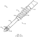
- FIGS. 1A and 1B depict a prior art anchor delivery system 100 for securing a tissue to bone.
- the anchor delivery system 100 generally includes a screw-in type anchor sleeve 101 and a pound-in type tip 102.
- the anchor sleeve 101 includes a plurality of turns of a screw thread 104 having a plurality of openings 106 between turns of the plurality of turns of a screw thread 104 for allowing bony ingrowth from the bone into an internal volume defined within the plurality of turns of a screw thread 104.
- the tip 102 includes a suture capture member, such as a plug (not shown), advanceable through an internal cavity of the tip 102 to lock one or more sutures in an eyelet 102a extending through the tip 102.
- the tip 102 may include barbs 108 protruding therefrom to improve pullout strength of the tip 102.
- the tip 102 may be smooth-sided.
- the anchor sleeve 101, the tip 102 and the plug can be constructed from polymers (e.g., PEEK), bioabsorbable materials, metals (e.g., surgical steel, titanium), or any other suitable material.
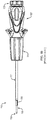
- the anchor sleeve 101 and the tip 102 can be installed into bone using a delivery device 115.
- the delivery device 115 generally includes an outer shaft 117 for engaging with the anchor sleeve 101, an inner shaft 103 for engaging with the plug of the tip 102, and a handle assembly 107 for holding and operating the delivery device 115.
- the delivery device 115 can also include one or more intermediate shafts 105 to provide additional stiffness when pounding in the tip 102.
- the internal volume of the anchor sleeve 101 may comprise longitudinal ribs to engage grooves or slots 108 extending along the outer shaft 117.
- the outer shaft 117 may comprise longitudinal ribs (not shown) to engage recesses extending through the internal volume of the anchor sleeve 101.
- the anchor sleeve 101 is screwed or otherwise advanced by the outer shaft 117 into bone over a proximal end of the tip 102 by rotation of a sleeve advancement member 111.
- a suture capture knob 109 is operatively coupled to a proximal end of the inner shaft 103 such that rotating or twisting the suture capture knob 109 causes the inner shaft 103 to advance the plug within the eyelet 102a of the tip 102. Additional non-limiting examples of anchor delivery systems can be found in U.S. Patent No. 9,526,488 , to Smith & Nephew, Inc. (Memphis, TN), the entire contents of which are incorporated herein by reference.
- the anchor delivery system 200 may be used to insert an anchor sleeve 201 and a tip, such as tip 102, into bone.
- the anchor delivery system 200 includes a delivery device 215 having an outer shaft 217 for engaging with the anchor sleeve 201.
- the anchor sleeve 201 comprises a substantially cylindrical sleeve body 210 having a proximal end 210a, a distal end 210b, and a plurality of turns of a screw thread 204 extending between the proximal end 210a and the distal end 210b.
- the distal end 210b of the sleeve body 210 can include a non-threaded portion, as shown.
- the sleeve body 210 defines an internal volume 212 which communicates with an exterior of the sleeve body 210 through at least one set axially-aligned openings 206 defined by the portions of the sleeve body 210 extending between adjacent turns of the screw thread 204.
- four sets of axially-aligned openings 206 are defined by the sleeve body 210. However, more or fewer than four sets of axially-aligned openings 206 are contemplated by this disclosure.
- Each set of axially-aligned openings 206 are spaced about 90° from another set of axially-aligned openings 206 around a circumference of the sleeve body 210.
- the sleeve body 210 also includes at least one slot 216 disposed within the internal volume 212 and extending between the proximal end 210a and the distal end 210b of the sleeve body 210.
- the sleeve body 210 includes four slots 216. However, more or fewer than four slots 216 are contemplated by this disclosure. Each slot 216 is spaced about 90° from another slot 216 around a surface of the interior volume 212 and is disposed between adjacent sets of axially-aligned openings 206.
- the outer shaft 217 of the delivery device 215 includes a proximal portion 217a and a distal portion 217b.
- An outer surface of the distal portion 217b includes a plurality of ridges 220 extending a length of the distal portion 217b.
- the distal portion 217b includes four ridges 220.
- Each ridge 220 is spaced about 90° from another ridge 220 around an outer surface of the outer shaft 217 and is defined by two substantially flat sides 222, 224 extending along a length of the ridge 220.
- Side 224 includes a first set of axially-aligned, laser-marked numerals 214, while side 222 includes a second set of axially-aligned, laser-marked numerals 218, the purpose of which will be described in more detail below.
- Each ridge 220 is configured to engage a respective slot 216 of the anchor body 210 when the distal portion 217b of the delivery device 215 is inserted into the interior volume 212 of the anchor body 210.
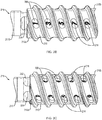
- FIG. 2B a detailed view of the sleeve body 210 and the distal portion 217b of the delivery device 215 is shown in an assembled view.
- the first set of laser marked numerals 214 which may be five numerals 214, on the side 224 of the delivery device 215, are visible through a first set of axially-aligned openings 206 of the sleeve body 210.
- the first set of numerals 214 count down in a stepwise fashion by odd numbers (e.g., 9, 7, 5, 3, 1) from the distal end 210b to the proximal end 210a of the sleeve body 210.
- FIG. 2C shows the sleeve body 210 of FIG.
- the second set of numerals 218 count down in a stepwise fashion by even numbers (e.g., 8, 6, 4, 2) from the distal end 210b to the proximal end 210a of the sleeve body 210.
- the first set of numerals 214 and second set of numerals 218 give the user visual feedback that the sleeve body 210 is inserting into bone, rather than merely free-spinning.
- a third set of laser marked numerals which may be five numerals, on an opposite side of the delivery device 215 from side 224, would be visible through a third set of axially-aligned openings 206 of the sleeve body 210.
- the third set of numerals would count down in a stepwise fashion by odd numbers from the distal end 210b to the proximal end 210a of the sleeve body 210. If the sleeve body 210 of FIG.
- a fourth set of laser marked numerals which may be four numerals, on an opposite side of the delivery device 215 from side 222, would be visible through a fourth set of axially-aligned openings 206 of the sleeve body 210.
- the fourth set of numerals would count down in a stepwise fashion by even numbers from the distal end 210b to the proximal end 210a of the sleeve body 210.
- other visual markings could be used to indicate the insertion progress of the anchor body 210 into bone.
- the markings could be a sequence of alternating characters, such as dots and dashes.
- the markings could be a sequence of dots of changing size, number and/or shape.
- the markings could be a series of dash lines with a changing azimuth angle.
- the tip 302 includes a distal portion 302c and a proximal portion 302b.
- a tip cavity 302d is defined within the proximal portion 302b of the tip 302 and is configured to receive the plug 313 through an opening in the proximal portion 302b.
- the eyelet 302a extends through the distal portion 302c of the tip 302 and is in communication with the tip cavity 302d.
- a distal end of the tip 302 may be pointed as shown, for creation of a bone hole.
- the plug 313 includes an internal cannulation 313b extending through the plug 313, while an outer surface of the plug 313 includes threads 313a.
- the threads 313a extend an entire length of the plug 313.
- only a proximal portion of the plug 313 is threaded, while a distal portion of the plug 313 is unthreaded.
- the tip cavity 302d includes threads 302e that engage the threads 313a of the plug 313 upon insertion of a portion of the plug 313 into the tip cavity 302d. In examples, the remainder of the plug 313 extends outside of the tip cavity 302d.
- the proximal portion 302b of the tip 302 when engaged with the delivery device, the proximal portion 302b of the tip 302 is coupled to the intermediate shaft 305, and the inner shaft 303 extends through the intermediate shaft 305 for engagement with the internal cannulation 313b of the plug 313.
- the internal cannulation 313b of the plug 313 and a mating portion of the inner shaft 303 having a corresponding geometry, such as a hexagonal shape.
- sutures 319 attached to soft tissue are placed through the eyelet 302a of the tip 302.
- a length of the inner shaft 303 is selected such that a gap or void 330 ( FIG.
- the void 330 may be empty of material, or may be filled with a material having a lower density than the plug 313.
- the void 330 thus provides a crushable zone at the distal end of the plug 313 which allows the distal end of the plug 313 to be deformable.
- the tip 302 is placed within a bone hole (not shown) via axial advancement, such as malleting, of the delivery device.
- the suture capture knob 109 of the delivery device 115 FIG.
- the plug 313 is rotated to move the plug 313 via the inner shaft 303 distally into the eyelet 302a where the plug 313 encounters the sutures 319.
- the plug 313 and the inner shaft 303 are descended further into the eyelet 302a, the plug 313 impinges on the sutures 319 with a force sufficient to deform the distal end of the plug 313 around the sutures 319, thus allowing for more surface contact between the sutures 319 and the plug 313.
- the increased surface contact between the plug 313 and the sutures 319 advantageously allows for more friction and holding force on the sutures 319 by the plug 313 within the eyelet 302a.
- FIG. 4A an example of an anchor delivery system 400 of this disclosure is shown in a perspective, exploded view.
- the anchor delivery system 400 may be used to insert an anchor sleeve 401 and a tip 402 into bone.
- the anchor delivery system 400 includes an outer shaft 417 for engaging with the sleeve 401, and an intermediate shaft 405 extending through the outer shaft 417 for engaging with the tip 402.
- a proximal end of the outer shaft 417 is coupled to an outer shaft hub 423.
- the outer shaft hub 423 in turn is configured to be threadingly coupled to a center housing 430.
- the anchor delivery system 400 also includes a drive housing 426 for holding the intermediate shaft 405.
- the anchor delivery system 400 furthermore includes a suture capture knob 409 coupled to the inner shaft 403 for advancing the plug 413 within the tip 402, a sleeve advancement member 411 for screwing the anchor sleeve 401 into bone, and a handle grip 425 for holding and/or maneuvering the anchor delivery system 400 during insertion of the anchor sleeve 401 into bone.
- a spring 432 is configured to be disposed within the drive housing 426 to allow a relative motion between the outer shaft 417 and the inner shaft 403, thereby absorbing at least a portion of the impact forces exerted on the sleeve 401 during the pounding-in of the tip structure 402.
- the anchor delivery system 400 may also include an anti-rotation feature, such as a bridge 434, which is described in more detail below.
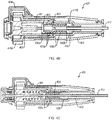
- FIG. 4B shows the internal components of the handle assembly 407 of the delivery device 415 of FIG. 4A in a cross-sectional view.
- FIG. 4B shows the sleeve advancement member 411 and the handle grip 425.
- a proximal end of the sleeve advancement member 411 defines a rotatable knob 411a extending outside of the handle grip 425 near the proximal end of the handle assembly 407.
- a proximal portion 430a of the center housing 430 may have internal threads 430c for engaging threads 423a on an outer surface of the outer shaft hub 423.
- a distal portion 430b of the center housing 430 may be unthreaded, forming a "spin cavity" 436, the purpose of which will be described in more detail below.
- the outer shaft hub 423 can be further engaged with a distal end 411b of the sleeve advancement member 411.
- twisting or rotating the sleeve advancement member 411 via the rotatable knob 411a rotates the outer shaft hub 423, thereby causing the outer shaft hub 423 to advance distally along the threads 430c of the center housing 430 and, consequently, to cause the outer shaft 417 to advance the sleeve 401 into engagement with bone and/or the tip 402.
- the bridge 434 is configured to stabilize the handle grip 425 to the drive housing 426, preventing the handle grip 425 from rotating during rotation of the sleeve advancement member 411.
- the bridge 434, the drive housing 426, the sleeve advancement member 411 and the handle grip 425 have built-in axial clearances to prevent these components from binding during use. Therefore, in the handle assembly 407 of this disclosure, a length of the bridge 434 is selected to place the bridge 434 in compression, like a spring. This compression causes the axial clearances between the components to be absorbed as the drive housing 426, the sleeve advancement member 411 and the handle grip 425 are forced into axial contact.
- the force generated by the bridge 434 being placed in compression forces the drive housing 426 and the handle grip 425 away from each other.
- the force generated by the bridge 434 being placed in compression is counteracted in the flexure joint between the sleeve advancement member 411 and the drive housing 426, and in the flexure joint between the handle grip 425 and the sleeve advancement member 411.
- the quantity of the axial force exerted by the bridge 434 is a function of the amount of built-in interference between the bridge 434 and the other components and by the stiffness of the bridge 434.
- a stiffness of the bridge 434 is selected such that a range of acceptable, non-zero axial loads are generated by the handle assembly 407 with the currently defined component tolerances.
- the outer shaft hub 423 is configured to fully unthread from the threads of the center housing 430 and freely rotate within the spin cavity 436.
- the free rotation of the outer shaft hub 423 within the spin cavity 436 may be sufficient to complete the insertion of the anchor sleeve 401 into bone. It is further contemplated that the threads may be entirely eliminated from both of the center housing 430 and the outer shaft hub 423, and that the free spinning of the outer shaft hub 423 within the center housing 430 is sufficient to insert the anchor sleeve 401 into bone.
- FIG. 5A another example of a handle assembly 507 of this disclosure is shown in a cross-sectional view.
- a length L of the threads 530c of the center housing 530 is selected to exceed a staging distance D between the distal end of the anchor sleeve 501 and the distal portion 502c of the tip 502 ( FIG. 5B ).
- the length L of the threads 530c allows the anchor sleeve 501 to undergo more handle-driven advancement, helping to address the issue of leaving the anchor sleeve 501 proud of the bone or tissue.
- the user first inserts the tip 502 into a bone hole.
- the threads 530c of the center housing 530 can be longer or shorter as long as the total length L of the threads 530c exceeds the distance D between the anchor sleeve 501 and the distal portion 502c of the tip 502.
- FIG. 6A an example of an unlocking instrument 600 of this disclosure for use with the anchor delivery systems 100, 200, 400 is shown in a side view.
- the unlocking instrument 600 is configured for removing a tip 602 from a suture 619 after the tip 602 has been deployed into bone.
- the unlocking instrument 600 has a similar working length to the working lengths of the anchor delivery systems 100, 200, 400 described above.
- the unlocking instrument 600 comprises a handle 625 and a shaft 603 extending from the handle 625.
- the handle 625 is made for single-use and is comprised of injection molded plastic.
- the handle 625 is reusable and comprised of stainless steel.
- a distal end of the shaft 603 comprises a hex feature 660 configured to mate with the hexagonal cannulation 613b of the plug 613 ( FIG. 6B ).
- the unlocking instrument 600 is used to loosen the contact between the plug 613 and the suture 619 secured within the tip 602, allowing for removal of the tip 602 from the suture 619.
- an instrument such as a grasper tool 662 is introduced into a repair site in which, for example, the anchor sleeve 601 has broken after insertion into bone.
- the tip 602 is held with the grasper tool 662 to stabilize the tip 602 during removal of the plug 613.
- the unlocking instrument 600 is then inserted into the proximal end 602b of the tip 602.
- the hex feature 660 of the unlocking instrument 600 is then engaged with the cannulation 613b of the plug 613.
- the unlocking instrument 600 is rotated to loosen the contact between the plug 613 and the suture 619 which has been threaded through the eyelet 602a. With the plug 613 loosened, the user can use the grasper tool 662 (or other means) to hold and slide the tip 602 off of the suture 619 and retrieve the tip 602 from the repair site. The user is then free to use a replacement anchor sleeve/tip with the suture 619 to complete the repair. It is also contemplated by this disclosure that the unlocking instrument 600 could also include a mechanism (not shown) for gripping the tip 602 during removal of the plug 613.
- FIGS. 7A and 7B an example of a hole preparation tool 700 of this disclosure for use with the anchor delivery systems 100, 200, 400 is shown in a side view ( FIG. 7A ) and a detailed view ( FIG. 7B ).
- the hole preparation tool 700 includes a handle grip 725 and a shaft 717 extending from the handle grip 725.
- the shaft 717 includes a distal pointed tip 742 for piercing bone.
- a threaded portion 701 of the hole preparation tool 700 may include a plurality of turns of a screw thread 704 for pre-tapping a bone hole before insertion of a threaded anchor sleeve.
- the hole preparation tool 700 also includes a marking element 738 disposed around the shaft 717 adjacent to a proximal end 710a of the threaded portion 701.
- the marking element 738 comprises an absorbent material pre-saturated with surgical ink.
- the marking element 738 has an annular shape, as shown. However, the disclosure contemplates other suitable shapes of the marking element 738, including two half-annuli.
- a protective cap 740 covers the tip 742 as well as the marking element 738 of the bone preparation tool 700.
- FIGS. 7D-G illustrate an example using the hole preparation tool 700 in a surgical repair.
- a surgeon first inserts the tip 742 of the hole preparation tool 700 into bone 744.
- the surgeons rotates the hole preparation tool 700 to advance the threaded portion 701 into the bone 744 until the marking element 738 comes into contact with the surface of the bone 744.
- the marking element 738 marks the bone 744 with ink.
- FIG. 7D a surgeon first inserts the tip 742 of the hole preparation tool 700 into bone 744.
- FIG. 7E the surgeons rotates the hole preparation tool 700 to advance the threaded portion 701 into the bone 744 until the marking element 738 comes into contact with the surface of the bone 744.
- the marking element 738 marks the bone 744 with ink.
- the surgeon then unthreads the hole preparation tool 700 and removes it from the repair site, leaving behind a prepared bone hole 746 and an ink mark 748 identifying the location of the prepared bone hole 746 ( FIG. 7G ).
- the disclosure also contemplates other methods of marking the bone hole 746, including using radio-frequency energy.
Landscapes
- Health & Medical Sciences (AREA)
- Surgery (AREA)
- Life Sciences & Earth Sciences (AREA)
- Animal Behavior & Ethology (AREA)
- Public Health (AREA)
- Engineering & Computer Science (AREA)
- Biomedical Technology (AREA)
- Heart & Thoracic Surgery (AREA)
- Medical Informatics (AREA)
- Molecular Biology (AREA)
- Veterinary Medicine (AREA)
- General Health & Medical Sciences (AREA)
- Nuclear Medicine, Radiotherapy & Molecular Imaging (AREA)
- Orthopedic Medicine & Surgery (AREA)
- Rheumatology (AREA)
- Oral & Maxillofacial Surgery (AREA)
- Pathology (AREA)
- Neurology (AREA)
- Dentistry (AREA)
- Surgical Instruments (AREA)
Abstract
Description
- This application claims priority to and benefit of
U.S. Provisional Application No. 62/993,322, filed March 23, 2020 U.S. Provisional Application No. 63/009,632, filed April 14, 2020 - Arthroscopic procedures often require soft tissue to be reattached to bone. To achieve this, anchors are typically placed in the bone and sutures attached to the anchor are passed through the tissue to securely retain the tissue in place. Typical anchors may be pound-in or screw-in type anchors, or combination anchors having a pound-in distal tip and a screw-in proximal anchor.
- Installation of combination pound-in/screw-in type anchors can be problematic due to several issues. One issue is the lack of prominent visual landmarks available to provide feedback to the user on the insertion progress of the anchor. This problem occurs both during the initial pound-in phase of the distal tip as well as during the subsequent screw-in phase of the proximal anchor. Another issue is that some current pound-in/screw-in type anchors include an internal locking plug advanceable within the tip for locking sutures within the tip eyelet. In some cases, insufficient suture retention by the locking plug can allow for the sutures to slip, and thus for the repair construct to loosen and fail.
- Another problem with pound-in/screw-in type anchors is that, in instances where there are large amounts of suture loaded into the anchor tip, rotatable parts of the inserter can sometimes reach a travel limit before the screw-in anchor is fully seated into bone. In these cases, the screw-in anchor is left proud of the cortical bone surface, which can lead to irritation of adjacent tissue. This issue is more common with poor quality bone, as the partially implanted anchor cannot finish "pulling" itself into the bone without the mechanical assist of the inserter. In these instances, the bone itself begins to mechanically fail under the loads required to drive the screw-in anchor into the bone hole. Furthermore, while surgeons can choose to abrade the exposed portion of the anchor, this may cause a delay in the progress of the surgery and risk damaging the repair suture.
- Another issue with pound-in/screw-in type anchors is that some handles of current anchor delivery systems have an excess of axial clearance between the component parts of the handle, giving an undesirable feeling of looseness within the handle as experienced by the user. Furthermore, if the screw-in portion of the anchor either breaks or pulls out of the bone intraoperatively, it is difficult to remove the distal tip from the repair suture in order to reload the suture into a backup anchor to complete the repair.
- Described herein are anchor delivery systems for combination pound-in/screw-in type anchors which include markings on the surfaces of the delivery device. The markings consist of countdown markers on the driver tip which are visually exposed to the user through openings or fenestrations in the screw-in portion of the anchor. The countdown markers create a countdown sequence for the user, which advantageously provides visual feedback to the user on the progress of the anchor's insertion. Also described herein is a suture-locking plug that is deformable within the anchor tip, and thereby enhances suture entrapment within the tip of the anchor. Additionally, a compliant component of the handle places the handle components in tension, thereby absorbing built-in axial looseness within the handle. In some examples, the handle further comprises a spin cavity which allows for free spin of the inserter shaft to finalize insertion of the screw-in anchor into bone when the screw-in anchor has not been fully seated flush with or below the cortical bone surface. In other examples, a length of internal threads of the delivery device is selected to allow the screw-in anchor to rotate for several turns without threading into the bone while still allowing sufficient axial travel of the screw-in anchor to fully seat into bone. Also disclosed are instruments that can be used by the surgeon to loosen the plug in the anchor tip, allowing for removal of the anchor tip from the repair suture, and to mark the site of a prepared bone hole for easy identification.
- Further examples of the anchor delivery systems of this disclosure may include one or more of the following, in any suitable combination.
- In examples, the anchor delivery system of this disclosure includes a sleeve body having a proximal end, a distal end, and a plurality of turns of a screw thread extending between the proximal and distal ends. The sleeve body defines an internal volume communicating with a region exterior to the sleeve body through at least one set of axially-aligned openings defined by the sleeve body between adjacent turns of the plurality of turns of screw thread along a length of the sleeve body. A delivery device has an elongated shaft having a proximal portion and a distal portion. The distal portion includes at least one ridge defined by first and second sides of the shaft. At least one of the first and second sides has a series of axially-aligned markings extending along a length of the at least one of the first and second sides. When the sleeve body is engaged with the distal portion of the shaft, each marking of the series of axially-aligned markings of the delivery device is visible through a respective opening of the at least one set of axially-aligned openings of the sleeve body, providing a user with visual feedback on insertion progress of the sleeve body into bone.
- In further examples, the internal volume of the sleeve body includes at least one slot extending between the proximal and distal ends of the sleeve body. When the sleeve body is engaged with the distal portion of the shaft, the at least one ridge of the delivery device is engageable with the at least one slot of the sleeve body. In examples, the at least one slot is four slots. Each slot is spaced about 90° around a surface of the internal volume of the sleeve body from another slot. In examples, the at least one set of axially-aligned openings is two sets of axially-aligned openings, and the at least one slot is positioned between the two sets of axially-aligned openings. In examples, the at least one set of axially-aligned openings is four sets of axially-aligned openings. Each set of axially-aligned openings is spaced about 90° around a circumference of the sleeve body from another set of axially-aligned openings. In examples, the at least one ridge is four ridges. Each ridge is spaced about 90° around a surface of the shaft of the delivery device from another ridge. In examples, the at least one set of axially-aligned markings is a set of numerals. In examples, the set of numerals includes five numerals which count down in a stepwise fashion by odd numbers from the distal end to the proximal end of the shaft. In other examples, the set of numerals includes four numerals which count down in a stepwise fashion by even numbers from the distal end to the proximal end of the shaft. In examples, the at least one set of axially-aligned openings is five axially-aligned openings. In other examples, the at least one set of axially-aligned openings is four axially-aligned openings.
- In further examples, the anchor delivery system of this disclosure includes a tip having a distal portion and a proximal portion. The proximal portion defines a cavity therein with a wall of the cavity having threads. An eyelet is defined in the distal portion of the tip in communication with the cavity. A plug has a threaded outer portion and an internal cannulation configured for receipt of an inner shaft of a delivery device. The plug is disposed within the cavity of the tip such that threads of the threaded outer portion are engaged with the threads of the cavity. The plug is rotatable and axially moveable through the cavity by rotation of the inner shaft to engage a suture threaded through the eyelet. When the inner shaft of the delivery device is disposed within the cannulation of the plug, a length of the inner shaft is selected such that a gap is formed between a distal end of the inner shaft and a distal end of the cannulation. The gap provides a crushable zone such that a distal end of the plug is deformable when the plug is engaged with the suture in the eyelet. In yet further examples, a proximal portion of the plug extends from the cavity of the tip. In other examples, the tip is coupled to an intermediate shaft of the delivery device such that the inner shaft extends through the intermediate shaft. In further examples, the plug includes a non-threaded outer portion. The non-threaded outer portion is distal to the threaded outer portion.
- In other examples, the anchor delivery system of this disclosure includes a handle assembly including a handle grip. An outer shaft extends from a distal end of the handle assembly. A proximal end of the outer shaft is coupled to an outer shaft hub. A sleeve advancement member is at least partially disposed within the handle assembly. A proximal end of the sleeve advancement member defines a rotatable knob adjacent a proximal end of the handle assembly. A distal end of the sleeve advancement member is operatively coupled to the outer shaft hub such that rotation of the rotatable knob causes rotational movement of the outer shaft. A drive housing is at least partially disposed within the sleeve advancement member. An anti-rotation member is coupled to the handle grip and the drive housing for preventing rotation of the handle grip during rotation of the rotatable knob. A length and stiffness of the anti-rotation member is selected to force the drive housing, the sleeve advancement member and the handle grip into axial contact to eliminate axial looseness in the handle assembly.
- In other examples, an anchor delivery system of this disclosure includes a handle assembly including a handle grip. An outer shaft extends from a distal end of the handle assembly. A proximal end of the outer shaft is coupled to an outer shaft hub. A sleeve advancement member is at least partially disposed within the handle assembly. A proximal end of the sleeve advancement member defines a rotatable knob adjacent a proximal end of the handle assembly. A distal end of the sleeve advancement member is operatively coupled to a center housing having internal threads configured to engage outer threads on the outer shaft hub, such that rotation of the rotatable knob causes rotational movement of the outer shaft. At an end of an axial travel limit of the outer shaft hub along the internal threads of the center housing, the outer shaft hub is configured to freely rotate within a non-threaded portion of the center housing. In further examples, the system includes an anti-rotation member coupled to the handle grip and a drive housing at least partially disposed within the sleeve advancement member. The anti-rotation member is configured to prevent rotation of the handle grip during rotation of the rotatable knob.
- In further examples, an anchor delivery system of this disclosure includes a handle assembly including a handle grip. A first shaft is coupled to the handle assembly. A proximal end of the first shaft coupled to a hub and a distal end of the first shaft is coupled to an anchor sleeve. A second shaft extends through the first shaft. A distal end of the second shaft is coupled to a tip having a proximal portion and a distal portion. A sleeve advancement member is at least partially disposed within the handle assembly. A proximal end of the sleeve advancement member defines a rotatable knob adjacent a proximal end of the handle assembly. A distal end of the sleeve advancement member is operatively coupled to a center housing having internal threads configured to engage outer threads on the hub such that rotation of the rotatable knob causes rotational movement of the first shaft. A length of the internal threads of the center housing is selected to exceed a distance between a distal end of the anchor sleeve and the distal portion of the tip.
- These and other features and advantages will be apparent from a reading of the following detailed description and a review of the associated drawings. It is to be understood that both the foregoing general description and the following detailed description are explanatory only and are not restrictive of aspects as claimed.
- The disclosure will be more fully understood by reference to the detailed description, in conjunction with the following figures, wherein:
-
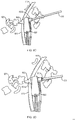
FIGS. 1A and1B illustrate a prior art anchor delivery system; -
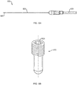
FIG. 2A illustrates an anchor sleeve portion of an anchor delivery system of this disclosure in an exploded view; -
FIGS. 2B and 2C are detailed illustrations of the anchor sleeve portion ofFIG. 2A in an assembled view; -
FIGS. 3A and 3B are detailed illustrations of a distal tip portion of another example of an anchor delivery system of this disclosure in a cross-sectional view; -
FIG. 4A illustrates another example of an anchor delivery system of this disclosure in an exploded view; -
FIGS. 4B and 4C illustrate the handle assembly of the anchor delivery system ofFIG. 4A in cross-sectional views; -
FIGS. 5A and 5B illustrate another handle assembly of the anchor delivery system of this disclosure; -
FIGS. 6A and 6B illustrate an unlocking instrument for use with the anchor delivery systems of this disclosure; -
FIGS. 6C and 6D illustrate the use of the unlocking instrument ofFIGS. 6A and 6B ; -
FIGS. 7A-C illustrate a hole preparation tool for use with the anchor delivery systems of this disclosure; and -
FIGS. 7D-G illustrate the use of the hole preparation tool ofFIGS. 7A-C . - In the description that follows, like components have been given the same reference numerals, regardless of whether they are shown in different examples. To illustrate example(s) in a clear and concise manner, the drawings may not necessarily be to scale and certain features may be shown in somewhat schematic form. Features that are described and/or illustrated with respect to one example may be used in the same way or in a similar way in one or more other examples and/or in combination with or instead of the features of the other examples.
- As used in the specification and claims, for the purposes of describing and defining the invention, the terms "about" and "substantially" are used to represent the inherent degree of uncertainty that may be attributed to any quantitative comparison, value, measurement, or other representation. The terms "about" and "substantially" are also used herein to represent the degree by which a quantitative representation may vary from a stated reference without resulting in a change in the basic function of the subject matter at issue. "Comprise," "include," and/or plural forms of each are open ended and include the listed parts and can include additional parts that are not listed. "And/or" is open-ended and includes one or more of the listed parts and combinations of the listed parts.
- For a better understanding of the current disclosure,
FIGS. 1A and1B depict a prior artanchor delivery system 100 for securing a tissue to bone. As shown inFIG. 1A , theanchor delivery system 100 generally includes a screw-intype anchor sleeve 101 and a pound-intype tip 102. In examples, theanchor sleeve 101 includes a plurality of turns of ascrew thread 104 having a plurality ofopenings 106 between turns of the plurality of turns of ascrew thread 104 for allowing bony ingrowth from the bone into an internal volume defined within the plurality of turns of ascrew thread 104. In examples, thetip 102 includes a suture capture member, such as a plug (not shown), advanceable through an internal cavity of thetip 102 to lock one or more sutures in aneyelet 102a extending through thetip 102. In examples, thetip 102 may includebarbs 108 protruding therefrom to improve pullout strength of thetip 102. However, in other examples, thetip 102 may be smooth-sided. In examples, theanchor sleeve 101, thetip 102 and the plug can be constructed from polymers (e.g., PEEK), bioabsorbable materials, metals (e.g., surgical steel, titanium), or any other suitable material. - As shown in more detail in
FIG. 1B , theanchor sleeve 101 and thetip 102 can be installed into bone using adelivery device 115. Thedelivery device 115 generally includes anouter shaft 117 for engaging with theanchor sleeve 101, aninner shaft 103 for engaging with the plug of thetip 102, and ahandle assembly 107 for holding and operating thedelivery device 115. In examples, thedelivery device 115 can also include one or moreintermediate shafts 105 to provide additional stiffness when pounding in thetip 102. In examples, the internal volume of theanchor sleeve 101 may comprise longitudinal ribs to engage grooves orslots 108 extending along theouter shaft 117. In other examples, theouter shaft 117 may comprise longitudinal ribs (not shown) to engage recesses extending through the internal volume of theanchor sleeve 101. In some examples, theanchor sleeve 101 is screwed or otherwise advanced by theouter shaft 117 into bone over a proximal end of thetip 102 by rotation of asleeve advancement member 111. In examples, asuture capture knob 109 is operatively coupled to a proximal end of theinner shaft 103 such that rotating or twisting thesuture capture knob 109 causes theinner shaft 103 to advance the plug within theeyelet 102a of thetip 102. Additional non-limiting examples of anchor delivery systems can be found inU.S. Patent No. 9,526,488 - Turning now to
FIG. 2A , an example of ananchor delivery system 200 of this disclosure is shown in an exploded, perspective view. Theanchor delivery system 200 may be used to insert ananchor sleeve 201 and a tip, such astip 102, into bone. As shown inFIG. 2A , theanchor delivery system 200 includes adelivery device 215 having anouter shaft 217 for engaging with theanchor sleeve 201. Theanchor sleeve 201 comprises a substantiallycylindrical sleeve body 210 having aproximal end 210a, adistal end 210b, and a plurality of turns of ascrew thread 204 extending between theproximal end 210a and thedistal end 210b. In examples, thedistal end 210b of thesleeve body 210 can include a non-threaded portion, as shown. Thesleeve body 210 defines aninternal volume 212 which communicates with an exterior of thesleeve body 210 through at least one set axially-alignedopenings 206 defined by the portions of thesleeve body 210 extending between adjacent turns of thescrew thread 204. In examples, four sets of axially-alignedopenings 206 are defined by thesleeve body 210. However, more or fewer than four sets of axially-alignedopenings 206 are contemplated by this disclosure. Each set of axially-alignedopenings 206 are spaced about 90° from another set of axially-alignedopenings 206 around a circumference of thesleeve body 210. Thesleeve body 210 also includes at least oneslot 216 disposed within theinternal volume 212 and extending between theproximal end 210a and thedistal end 210b of thesleeve body 210. In examples, thesleeve body 210 includes fourslots 216. However, more or fewer than fourslots 216 are contemplated by this disclosure. Eachslot 216 is spaced about 90° from anotherslot 216 around a surface of theinterior volume 212 and is disposed between adjacent sets of axially-alignedopenings 206. - Still referring to
FIG. 2A , theouter shaft 217 of thedelivery device 215 includes aproximal portion 217a and adistal portion 217b. An outer surface of thedistal portion 217b includes a plurality ofridges 220 extending a length of thedistal portion 217b. In examples, thedistal portion 217b includes fourridges 220. However, more or fewer than fourridges 220 are contemplated by this disclosure. Eachridge 220 is spaced about 90° from anotherridge 220 around an outer surface of theouter shaft 217 and is defined by two substantiallyflat sides ridge 220.Side 224 includes a first set of axially-aligned, laser-markednumerals 214, whileside 222 includes a second set of axially-aligned, laser-markednumerals 218, the purpose of which will be described in more detail below. Eachridge 220 is configured to engage arespective slot 216 of theanchor body 210 when thedistal portion 217b of thedelivery device 215 is inserted into theinterior volume 212 of theanchor body 210. - Turning now to
FIG. 2B , a detailed view of thesleeve body 210 and thedistal portion 217b of thedelivery device 215 is shown in an assembled view. InFIG. 2B , the first set of laser markednumerals 214, which may be fivenumerals 214, on theside 224 of thedelivery device 215, are visible through a first set of axially-alignedopenings 206 of thesleeve body 210. The first set ofnumerals 214 count down in a stepwise fashion by odd numbers (e.g., 9, 7, 5, 3, 1) from thedistal end 210b to theproximal end 210a of thesleeve body 210.FIG. 2C shows thesleeve body 210 ofFIG. 2B rotated clockwise by about 1/8th of a turn. As seen inFIG. 2C , the second set of laser markednumerals 218, which may be four numerals, on theside 222 of thedelivery device 215, are visible through a second set of axially-alignedopenings 206 of thesleeve body 210. The second set ofnumerals 218 count down in a stepwise fashion by even numbers (e.g., 8, 6, 4, 2) from thedistal end 210b to theproximal end 210a of thesleeve body 210. In use, as thesleeve body 210 is inserted into bone via rotation of theouter shaft 217, the first set ofnumerals 214 and second set ofnumerals 218 give the user visual feedback that thesleeve body 210 is inserting into bone, rather than merely free-spinning. - It will be appreciated that, if the
sleeve body 210 ofFIG. 2C were again rotated clockwise, a third set of laser marked numerals, which may be five numerals, on an opposite side of thedelivery device 215 fromside 224, would be visible through a third set of axially-alignedopenings 206 of thesleeve body 210. The third set of numerals would count down in a stepwise fashion by odd numbers from thedistal end 210b to theproximal end 210a of thesleeve body 210. If thesleeve body 210 ofFIG. 2C were further rotated clockwise, a fourth set of laser marked numerals, which may be four numerals, on an opposite side of thedelivery device 215 fromside 222, would be visible through a fourth set of axially-alignedopenings 206 of thesleeve body 210. The fourth set of numerals would count down in a stepwise fashion by even numbers from thedistal end 210b to theproximal end 210a of thesleeve body 210. It is also contemplated by this disclosure that, rather than numerals, other visual markings could be used to indicate the insertion progress of theanchor body 210 into bone. For example, the markings could be a sequence of alternating characters, such as dots and dashes. In other examples, the markings could be a sequence of dots of changing size, number and/or shape. In further examples, the markings could be a series of dash lines with a changing azimuth angle. - Turning now to
FIG. 3A , examples of atip 302, aninner shaft 303, anintermediate shaft 305, and a lockingplug 313 are illustrated in a cross-sectional, detailed view. In examples, thetip 302 includes a distal portion 302c and aproximal portion 302b. Atip cavity 302d is defined within theproximal portion 302b of thetip 302 and is configured to receive theplug 313 through an opening in theproximal portion 302b. Theeyelet 302a extends through the distal portion 302c of thetip 302 and is in communication with thetip cavity 302d. In examples, a distal end of thetip 302 may be pointed as shown, for creation of a bone hole. However, it contemplated by this disclosure that the distal end of thetip 302 may be blunt in cases where a bone hole is created prior to insertion of thetip 302. Theplug 313 includes aninternal cannulation 313b extending through theplug 313, while an outer surface of theplug 313 includesthreads 313a. In examples, thethreads 313a extend an entire length of theplug 313. In other examples, as shown, only a proximal portion of theplug 313 is threaded, while a distal portion of theplug 313 is unthreaded. Thetip cavity 302d includesthreads 302e that engage thethreads 313a of theplug 313 upon insertion of a portion of theplug 313 into thetip cavity 302d. In examples, the remainder of theplug 313 extends outside of thetip cavity 302d. - Still referring to
FIG. 3A , when engaged with the delivery device, theproximal portion 302b of thetip 302 is coupled to theintermediate shaft 305, and theinner shaft 303 extends through theintermediate shaft 305 for engagement with theinternal cannulation 313b of theplug 313. In examples, theinternal cannulation 313b of theplug 313 and a mating portion of theinner shaft 303 having a corresponding geometry, such as a hexagonal shape. During tissue repair,sutures 319 attached to soft tissue (not shown) are placed through theeyelet 302a of thetip 302. A length of theinner shaft 303 is selected such that a gap or void 330 (FIG. 3B ) is formed between the distal end of theinner shaft 303 and the distal end of theinternal cannulation 313b of theplug 313. The void 330 may be empty of material, or may be filled with a material having a lower density than theplug 313. The void 330 thus provides a crushable zone at the distal end of theplug 313 which allows the distal end of theplug 313 to be deformable. In use, thetip 302 is placed within a bone hole (not shown) via axial advancement, such as malleting, of the delivery device. Thesuture capture knob 109 of the delivery device 115 (FIG. 1B ) is rotated to move theplug 313 via theinner shaft 303 distally into theeyelet 302a where theplug 313 encounters thesutures 319. As theplug 313 and theinner shaft 303 are descended further into theeyelet 302a, theplug 313 impinges on thesutures 319 with a force sufficient to deform the distal end of theplug 313 around thesutures 319, thus allowing for more surface contact between thesutures 319 and theplug 313. The increased surface contact between theplug 313 and thesutures 319 advantageously allows for more friction and holding force on thesutures 319 by theplug 313 within theeyelet 302a. - Turning now to
FIG. 4A , an example of ananchor delivery system 400 of this disclosure is shown in a perspective, exploded view. Theanchor delivery system 400 may be used to insert ananchor sleeve 401 and atip 402 into bone. As shown inFIG. 4A , theanchor delivery system 400 includes anouter shaft 417 for engaging with thesleeve 401, and anintermediate shaft 405 extending through theouter shaft 417 for engaging with thetip 402. A proximal end of theouter shaft 417 is coupled to anouter shaft hub 423. Theouter shaft hub 423 in turn is configured to be threadingly coupled to acenter housing 430. Theanchor delivery system 400 also includes adrive housing 426 for holding theintermediate shaft 405. Theanchor delivery system 400 furthermore includes asuture capture knob 409 coupled to theinner shaft 403 for advancing theplug 413 within thetip 402, asleeve advancement member 411 for screwing theanchor sleeve 401 into bone, and ahandle grip 425 for holding and/or maneuvering theanchor delivery system 400 during insertion of theanchor sleeve 401 into bone. Aspring 432 is configured to be disposed within thedrive housing 426 to allow a relative motion between theouter shaft 417 and theinner shaft 403, thereby absorbing at least a portion of the impact forces exerted on thesleeve 401 during the pounding-in of thetip structure 402. Theanchor delivery system 400 may also include an anti-rotation feature, such as abridge 434, which is described in more detail below. -
FIG. 4B shows the internal components of thehandle assembly 407 of the delivery device 415 ofFIG. 4A in a cross-sectional view. In particular,FIG. 4B shows thesleeve advancement member 411 and thehandle grip 425. A proximal end of thesleeve advancement member 411 defines arotatable knob 411a extending outside of thehandle grip 425 near the proximal end of thehandle assembly 407. In examples, aproximal portion 430a of thecenter housing 430 may have internal threads 430c for engagingthreads 423a on an outer surface of theouter shaft hub 423. Adistal portion 430b of thecenter housing 430 may be unthreaded, forming a "spin cavity" 436, the purpose of which will be described in more detail below. Theouter shaft hub 423 can be further engaged with adistal end 411b of thesleeve advancement member 411. Thus, twisting or rotating thesleeve advancement member 411 via therotatable knob 411a rotates theouter shaft hub 423, thereby causing theouter shaft hub 423 to advance distally along the threads 430c of thecenter housing 430 and, consequently, to cause theouter shaft 417 to advance thesleeve 401 into engagement with bone and/or thetip 402. - Still referring to
FIG. 4B , thebridge 434 is configured to stabilize thehandle grip 425 to thedrive housing 426, preventing thehandle grip 425 from rotating during rotation of thesleeve advancement member 411. In their natural state, thebridge 434, thedrive housing 426, thesleeve advancement member 411 and thehandle grip 425 have built-in axial clearances to prevent these components from binding during use. Therefore, in thehandle assembly 407 of this disclosure, a length of thebridge 434 is selected to place thebridge 434 in compression, like a spring. This compression causes the axial clearances between the components to be absorbed as thedrive housing 426, thesleeve advancement member 411 and thehandle grip 425 are forced into axial contact. Specifically, the force generated by thebridge 434 being placed in compression forces thedrive housing 426 and thehandle grip 425 away from each other. The force generated by thebridge 434 being placed in compression is counteracted in the flexure joint between thesleeve advancement member 411 and thedrive housing 426, and in the flexure joint between thehandle grip 425 and thesleeve advancement member 411. The quantity of the axial force exerted by thebridge 434 is a function of the amount of built-in interference between thebridge 434 and the other components and by the stiffness of thebridge 434. Thus, a stiffness of thebridge 434 is selected such that a range of acceptable, non-zero axial loads are generated by thehandle assembly 407 with the currently defined component tolerances. These generated axial loads advantageously remove axial clearance from the components of thehandle assembly 407, thus eliminating a feeling of looseness in thehandle assembly 407 as experienced by the user. It is also contemplated by this disclosure that other compression mechanisms than thebridge 434 could be used to axially load thehandle assembly 407. In addition, the amount of interference could be set on eachindividual handle assembly 407 with shims (not shown) to closely tune the compression force and feel of eachindividual handle assembly 407. - Turning now to
FIG. 4C , in some cases, some of the available travel of theouter shaft hub 423 within thecenter housing 430 is consumed while theanchor sleeve 401 spins at the bone surface without entering the bone. This can prevent theanchor sleeve 401 from being fully seated flush with or below the cortical bone surface, which is the desired outcome. Thus, in thehandle assembly 407 of this disclosure, at the end of the distal travel of theouter shaft hub 423 within thecenter housing 430, theouter shaft hub 423 is configured to fully unthread from the threads of thecenter housing 430 and freely rotate within thespin cavity 436. If theanchor sleeve 401 has not been fully seated flush with or below the cortical surface of bone, the free rotation of theouter shaft hub 423 within thespin cavity 436 may be sufficient to complete the insertion of theanchor sleeve 401 into bone. It is further contemplated that the threads may be entirely eliminated from both of thecenter housing 430 and theouter shaft hub 423, and that the free spinning of theouter shaft hub 423 within thecenter housing 430 is sufficient to insert theanchor sleeve 401 into bone. - Turning to
FIG. 5A , another example of ahandle assembly 507 of this disclosure is shown in a cross-sectional view. In thehandle assembly 507, a length L of the threads 530c of thecenter housing 530 is selected to exceed a staging distance D between the distal end of theanchor sleeve 501 and thedistal portion 502c of the tip 502 (FIG. 5B ). The length L of the threads 530c allows theanchor sleeve 501 to undergo more handle-driven advancement, helping to address the issue of leaving theanchor sleeve 501 proud of the bone or tissue. In use, the user first inserts thetip 502 into a bone hole. The user then activates the plug (for example, plug 313, 413) into thetip 502 prior to inserting theanchor sleeve 501 into engagement with thetip 502. Activating the plug releases thetip 502 from theintermediate shaft 505 of thedelivery device 515. If theanchor sleeve 501 rotates without inserting into bone, the mechanical action of thedelivery device 515 will withdraw theintermediate shaft 505 from the bone hole. However, because thetip 502 has been released from theintermediate shaft 505, thetip 502 generally remains at its fully deployed, distal location. The user can then rotate theanchor sleeve 501 without theanchor sleeve 501 threading into the bone for several turns of thesleeve advancement member 511 without fear of running out of mechanically assisted axial travel from thedelivery device 515. In examples, the threads 530c of thecenter housing 530 can be longer or shorter as long as the total length L of the threads 530c exceeds the distance D between theanchor sleeve 501 and thedistal portion 502c of thetip 502. - Turning now to
FIG. 6A , an example of an unlockinginstrument 600 of this disclosure for use with theanchor delivery systems instrument 600 is configured for removing atip 602 from asuture 619 after thetip 602 has been deployed into bone. The unlockinginstrument 600 has a similar working length to the working lengths of theanchor delivery systems FIG. 6A , the unlockinginstrument 600 comprises ahandle 625 and ashaft 603 extending from thehandle 625. In examples, thehandle 625 is made for single-use and is comprised of injection molded plastic. In other examples, thehandle 625 is reusable and comprised of stainless steel. A distal end of theshaft 603 comprises ahex feature 660 configured to mate with thehexagonal cannulation 613b of the plug 613 (FIG. 6B ). Thus, the unlockinginstrument 600 is used to loosen the contact between theplug 613 and thesuture 619 secured within thetip 602, allowing for removal of thetip 602 from thesuture 619. - Turning now to
FIG. 6C , in use, an instrument such as agrasper tool 662 is introduced into a repair site in which, for example, theanchor sleeve 601 has broken after insertion into bone. Thetip 602 is held with thegrasper tool 662 to stabilize thetip 602 during removal of theplug 613. The unlockinginstrument 600 is then inserted into theproximal end 602b of thetip 602. As shown inFIG. 6D , thehex feature 660 of the unlockinginstrument 600 is then engaged with thecannulation 613b of theplug 613. Once the unlockinginstrument 600 is engaged with theplug 613, the unlockinginstrument 600 is rotated to loosen the contact between theplug 613 and thesuture 619 which has been threaded through theeyelet 602a. With theplug 613 loosened, the user can use the grasper tool 662 (or other means) to hold and slide thetip 602 off of thesuture 619 and retrieve thetip 602 from the repair site. The user is then free to use a replacement anchor sleeve/tip with thesuture 619 to complete the repair. It is also contemplated by this disclosure that the unlockinginstrument 600 could also include a mechanism (not shown) for gripping thetip 602 during removal of theplug 613. - Turning now to
FIGS. 7A and 7B , an example of ahole preparation tool 700 of this disclosure for use with theanchor delivery systems FIG. 7A ) and a detailed view (FIG. 7B ). As shown inFIGS. 7A and 7B , thehole preparation tool 700 includes ahandle grip 725 and ashaft 717 extending from thehandle grip 725. In examples, theshaft 717 includes a distalpointed tip 742 for piercing bone. A threadedportion 701 of thehole preparation tool 700 may include a plurality of turns of ascrew thread 704 for pre-tapping a bone hole before insertion of a threaded anchor sleeve. Thehole preparation tool 700 also includes a markingelement 738 disposed around theshaft 717 adjacent to a proximal end 710a of the threadedportion 701. In examples, the markingelement 738 comprises an absorbent material pre-saturated with surgical ink. In examples, the markingelement 738 has an annular shape, as shown. However, the disclosure contemplates other suitable shapes of the markingelement 738, including two half-annuli. As shown inFIG. 7C , to protect thetip 742 from puncturing surrounding packaging and to protect the markingelement 738 from drying out, aprotective cap 740 covers thetip 742 as well as the markingelement 738 of thebone preparation tool 700. -
FIGS. 7D-G illustrate an example using thehole preparation tool 700 in a surgical repair. As shown inFIG. 7D , a surgeon first inserts thetip 742 of thehole preparation tool 700 intobone 744. Next, as shown inFIG. 7E , the surgeons rotates thehole preparation tool 700 to advance the threadedportion 701 into thebone 744 until the markingelement 738 comes into contact with the surface of thebone 744. When the markingelement 738 contacts the surface of thebone 744, the markingelement 738 marks thebone 744 with ink. As shown inFIG. 7F , the surgeon then unthreads thehole preparation tool 700 and removes it from the repair site, leaving behind aprepared bone hole 746 and anink mark 748 identifying the location of the prepared bone hole 746 (FIG. 7G ). The disclosure also contemplates other methods of marking thebone hole 746, including using radio-frequency energy. - While the disclosure has been particularly shown and described with references to preferred examples thereof, it will be understood by those skilled in the art that various changes in form and details may be made therein without departing from the spirit and scope of the present application as defined by the appended claims. Such variations are intended to be covered by the scope of this present application. As such, the foregoing description of examples of the present application is not intended to be limiting, the full scope rather being conveyed by the appended claims.
Claims (15)
- An anchor delivery system comprising:an sleeve body having a proximal end, a distal end, and a plurality of turns of a screw thread extending between the proximal and distal ends, the sleeve body defining an internal volume communicating with a region exterior to the sleeve body through at least one set of axially-aligned openings defined by the sleeve body between adjacent turns of the plurality of turns of screw thread along a length of the sleeve body; andan delivery device comprising an elongated shaft having a proximal portion and a distal portion, the distal portion including at least one ridge defined by first and second sides of the shaft, at least one of the first and second sides comprising a series of axially-aligned markings extending along a length of the at least one of the first and second sides;wherein, when the sleeve body is engaged with the distal portion of the shaft, each marking of the series of axially-aligned markings of the delivery device is visible through a respective opening of the at least one set of axially-aligned openings of the sleeve body, providing a user with visual feedback on insertion progress of the sleeve body into bone.
- The anchor delivery system of claim 1, wherein the internal volume of the sleeve body comprises at least one slot extending between the proximal and distal ends of the sleeve body, and wherein, when the sleeve body is engaged with the distal portion of the shaft, the at least one ridge of the delivery device is engageable with the at least one slot of the sleeve body.
- The anchor delivery system of claim 2, wherein the at least one slot is four slots, each slot being spaced about 90° around a surface of the internal volume of the sleeve body from another slot.
- The anchor delivery system of claim 2, wherein the at least one set of axially-aligned openings is two sets of axially-aligned openings, and wherein the at least one slot is positioned between the two sets of axially-aligned openings.
- The anchor delivery system of claim 1, wherein the at least one set of axially-aligned openings is four sets of axially-aligned openings, each set of axially-aligned openings being spaced about 90° around a circumference of the sleeve body from another set of axially-aligned openings.
- The anchor delivery system of claim 1, wherein the at least one ridge is four ridges, each ridge being spaced about 90° around a surface of the shaft of the delivery device from another ridge.
- The anchor delivery system of claim 1, wherein the at least one set of axially-aligned markings comprises a set of numerals.
- The anchor delivery system of claim 7, wherein the set of numerals includes five numerals which count down in a stepwise fashion by odd numbers from the distal end to the proximal end of the shaft.
- The anchor delivery system of claim 7, wherein the set of numerals includes four numerals which count down in a stepwise fashion by even numbers from the distal end to the proximal end of the shaft.
- The anchor delivery system of claim 1, wherein the at least one set of axially-aligned openings comprises five axially-aligned openings.
- The anchor delivery system of claim 1, wherein the at least one set of axially-aligned openings comprises four axially-aligned openings.
- An anchor delivery system comprising:a tip comprising a distal portion and a proximal portion, the proximal portion defining a cavity therein with a wall of the cavity having threads, and an eyelet defined in the distal portion of the tip in communication with the cavity; anda plug having a threaded outer portion and an internal cannulation configured for receipt of an inner shaft of a delivery device, the plug disposed within the cavity of the tip such that threads of the threaded outer portion are engaged with the threads of the cavity, the plug being rotatable and axially moveable through the cavity by rotation of the inner shaft to engage a suture threaded through the eyelet; andwherein, when the inner shaft of the delivery device is disposed within the cannulation of the plug, a length of the inner shaft is selected such that a gap is formed between a distal end of the inner shaft and a distal end of the cannulation, the gap providing a crushable zone such that a distal end of the plug is deformable when the plug is engaged with the suture in the eyelet.
- The anchor delivery system of claim 12, wherein a proximal portion of the plug extends from the cavity of the tip.
- The anchor delivery system of claim 12, wherein the tip is coupled to an intermediate shaft of the delivery device such that the inner shaft extends through the intermediate shaft.
- The anchor delivery system of claim 12, wherein the plug further comprises a non-threaded outer portion, the non-threaded outer portion being distal to the threaded outer portion.
Applications Claiming Priority (2)
| Application Number | Priority Date | Filing Date | Title |
|---|---|---|---|
| US202062993322P | 2020-03-23 | 2020-03-23 | |
| US202063009632P | 2020-04-14 | 2020-04-14 |
Publications (3)
| Publication Number | Publication Date |
|---|---|
| EP3884876A2 true EP3884876A2 (en) | 2021-09-29 |
| EP3884876A3 EP3884876A3 (en) | 2021-11-10 |
| EP3884876B1 EP3884876B1 (en) | 2025-01-08 |
Family
ID=74844730
Family Applications (1)
| Application Number | Title | Priority Date | Filing Date |
|---|---|---|---|
| EP21159774.5A Active EP3884876B1 (en) | 2020-03-23 | 2021-02-26 | Anchor delivery systems |
Country Status (5)
| Country | Link |
|---|---|
| US (1) | US11648002B2 (en) |
| EP (1) | EP3884876B1 (en) |
| JP (1) | JP7651318B2 (en) |
| CN (1) | CN113425349B (en) |
| AU (1) | AU2021201202B2 (en) |
Families Citing this family (3)
| Publication number | Priority date | Publication date | Assignee | Title |
|---|---|---|---|---|
| US11554197B2 (en) * | 2018-11-20 | 2023-01-17 | BioMark, LLC | Device with an open cell element |
| US20240057990A1 (en) * | 2022-08-22 | 2024-02-22 | Anika Therapeutics, Inc. | Suture anchor |
| US12672866B2 (en) | 2023-05-26 | 2026-07-07 | Wright Medical Technology, Inc. | Syndesmosis device inserter |
Citations (1)
| Publication number | Priority date | Publication date | Assignee | Title |
|---|---|---|---|---|
| US9526488B2 (en) | 2013-03-15 | 2016-12-27 | Smith & Nephew, Inc. | Fenestrated locking suture anchor assembly |
Family Cites Families (20)
| Publication number | Priority date | Publication date | Assignee | Title |
|---|---|---|---|---|
| US6030162A (en) * | 1998-12-18 | 2000-02-29 | Acumed, Inc. | Axial tension screw |
| US20100179573A1 (en) * | 2006-10-31 | 2010-07-15 | Core Essence Orthopaedics, Llc | Medical device and procedure for attaching tissue to bone |
| US8974494B2 (en) * | 2008-07-17 | 2015-03-10 | Smith & Nephew, Inc. | Surgical devices |
| US9050077B2 (en) * | 2008-09-18 | 2015-06-09 | Smith & Nephew, Inc. | Suture anchor inserter |
| RU2562601C2 (en) * | 2009-11-10 | 2015-09-10 | Смит Энд Нефью, Инк. | Device for tissue repair (versions) |
| BR112012010998A2 (en) * | 2009-11-10 | 2016-04-12 | Smith & Nephew Inc | locking suture anchor set |
| US9775702B2 (en) * | 2010-03-10 | 2017-10-03 | Smith & Nephew, Inc. | Composite interference screws and drivers |
| US9308080B2 (en) * | 2010-03-10 | 2016-04-12 | Smith & Nephew Inc. | Composite interference screws and drivers |
| US9883899B2 (en) * | 2010-03-18 | 2018-02-06 | Smith & Nephew, Inc. | Device and method for use during ligament reconstruction |
| MX2013010810A (en) * | 2011-03-22 | 2014-02-19 | Smith & Nephew Inc | Anchor system and delivery device for use therewith. |
| US9265494B2 (en) * | 2011-12-20 | 2016-02-23 | Medos International Sarl | Knotless instability anchor |
| ES2563758T3 (en) * | 2012-06-18 | 2016-03-16 | Biedermann Technologies Gmbh & Co. Kg | Bone anchor |
| US9451954B2 (en) * | 2013-03-15 | 2016-09-27 | Howmedica Osteonics Corp. | Ratcheting inserter device and suture anchor arrangement |
| MX2016011559A (en) * | 2014-03-06 | 2017-04-13 | Smith & Nephew Inc | Two-piece knotless suture anchor. |
| WO2016154406A1 (en) * | 2015-03-24 | 2016-09-29 | Smith & Nephew, Inc. | Bone anchor system having movable medial eyelet |
| EP3316794B1 (en) * | 2015-06-30 | 2021-01-20 | Smith & Nephew, Inc | Suture anchor system with threaded plug |
| US9924935B2 (en) * | 2015-10-23 | 2018-03-27 | Smith & Nephew, Inc. | Suture anchor assembly with slip fit tip |
| EP4631440A3 (en) * | 2015-12-16 | 2025-12-17 | ConMed Corporation | Knotless suture anchor and deployment device |
| US10820915B2 (en) * | 2018-03-06 | 2020-11-03 | Medos International Sarl | Methods, systems, and devices for instability repair |
| US11026674B2 (en) * | 2018-05-18 | 2021-06-08 | Biomet Manufacturing, Llc | Anchoring system and method for securing a suture to a pre-drilled hole |
-
2021
- 2021-02-24 AU AU2021201202A patent/AU2021201202B2/en active Active
- 2021-02-26 EP EP21159774.5A patent/EP3884876B1/en active Active
- 2021-03-02 CN CN202110230156.9A patent/CN113425349B/en active Active
- 2021-03-03 JP JP2021033401A patent/JP7651318B2/en active Active
- 2021-03-17 US US17/203,881 patent/US11648002B2/en active Active
Patent Citations (1)
| Publication number | Priority date | Publication date | Assignee | Title |
|---|---|---|---|---|
| US9526488B2 (en) | 2013-03-15 | 2016-12-27 | Smith & Nephew, Inc. | Fenestrated locking suture anchor assembly |
Also Published As
| Publication number | Publication date |
|---|---|
| AU2021201202B2 (en) | 2026-02-19 |
| JP2021146209A (en) | 2021-09-27 |
| AU2021201202A1 (en) | 2021-10-07 |
| EP3884876A3 (en) | 2021-11-10 |
| US11648002B2 (en) | 2023-05-16 |
| CN113425349A (en) | 2021-09-24 |
| CN113425349B (en) | 2026-03-24 |
| US20210290218A1 (en) | 2021-09-23 |
| JP7651318B2 (en) | 2025-03-26 |
| EP3884876B1 (en) | 2025-01-08 |
Similar Documents
| Publication | Publication Date | Title |
|---|---|---|
| US20200155143A1 (en) | Threaded suture anchor | |
| EP1954199B1 (en) | Suture anchor | |
| EP3884876B1 (en) | Anchor delivery systems | |
| US5941882A (en) | Medical screw particularly for surgery and emplacement tool | |
| US6685728B2 (en) | Threaded suture anchor and method of use | |
| US5626613A (en) | Corkscrew suture anchor and driver | |
| US6666877B2 (en) | Apparatus and method for securing suture to bone | |
| JP4864276B2 (en) | Medical screw and its mounting method | |
| EP3332715B1 (en) | Dual thread cannulated suture anchor | |
| EP2568899B1 (en) | Bone screw assembly and instruments for implantation of the same | |
| EP2772212B1 (en) | Instrument for inserting a bone anchoring element and system of such an instrument and a polyaxial bone anchoring element | |
| US20040243178A1 (en) | Push-in suture anchor, insertion tool, and method for inserting a push-in suture anchor | |
| EP1797825B1 (en) | Suture anchor with insert-molded suture eyelet | |
| AU2002367551A1 (en) | Threaded suture anchor and method of use | |
| EP1797828B1 (en) | Threaded suture anchor with starting pitch | |
| EP4051131B1 (en) | Healicoil knotless distal tip and plug transmission | |
| US7837709B2 (en) | Bone fixation means |
Legal Events
| Date | Code | Title | Description |
|---|---|---|---|
| PUAI | Public reference made under article 153(3) epc to a published international application that has entered the european phase |
Free format text: ORIGINAL CODE: 0009012 |
|
| STAA | Information on the status of an ep patent application or granted ep patent |
Free format text: STATUS: THE APPLICATION HAS BEEN PUBLISHED |
|
| AK | Designated contracting states |
Kind code of ref document: A2 Designated state(s): AL AT BE BG CH CY CZ DE DK EE ES FI FR GB GR HR HU IE IS IT LI LT LU LV MC MK MT NL NO PL PT RO RS SE SI SK SM TR |
|
| PUAL | Search report despatched |
Free format text: ORIGINAL CODE: 0009013 |
|
| AK | Designated contracting states |
Kind code of ref document: A3 Designated state(s): AL AT BE BG CH CY CZ DE DK EE ES FI FR GB GR HR HU IE IS IT LI LT LU LV MC MK MT NL NO PL PT RO RS SE SI SK SM TR |
|
| RIC1 | Information provided on ipc code assigned before grant |
Ipc: A61B 17/04 20060101AFI20211006BHEP |
|
| STAA | Information on the status of an ep patent application or granted ep patent |
Free format text: STATUS: REQUEST FOR EXAMINATION WAS MADE |
|
| 17P | Request for examination filed |
Effective date: 20220510 |
|
| RBV | Designated contracting states (corrected) |
Designated state(s): AL AT BE BG CH CY CZ DE DK EE ES FI FR GB GR HR HU IE IS IT LI LT LU LV MC MK MT NL NO PL PT RO RS SE SI SK SM TR |
|
| GRAP | Despatch of communication of intention to grant a patent |
Free format text: ORIGINAL CODE: EPIDOSNIGR1 |
|
| STAA | Information on the status of an ep patent application or granted ep patent |
Free format text: STATUS: GRANT OF PATENT IS INTENDED |
|
| RIC1 | Information provided on ipc code assigned before grant |
Ipc: A61B 17/00 20060101ALN20240731BHEP Ipc: A61B 90/00 20160101ALN20240731BHEP Ipc: A61B 17/16 20060101ALI20240731BHEP Ipc: A61B 17/88 20060101ALI20240731BHEP Ipc: A61B 17/86 20060101ALI20240731BHEP Ipc: A61B 17/04 20060101AFI20240731BHEP |
|
| INTG | Intention to grant announced |
Effective date: 20240812 |
|
| P01 | Opt-out of the competence of the unified patent court (upc) registered |
Free format text: CASE NUMBER: APP_49205/2024 Effective date: 20240830 |
|
| GRAS | Grant fee paid |
Free format text: ORIGINAL CODE: EPIDOSNIGR3 |
|
| GRAA | (expected) grant |
Free format text: ORIGINAL CODE: 0009210 |
|
| STAA | Information on the status of an ep patent application or granted ep patent |
Free format text: STATUS: THE PATENT HAS BEEN GRANTED |
|
| AK | Designated contracting states |
Kind code of ref document: B1 Designated state(s): AL AT BE BG CH CY CZ DE DK EE ES FI FR GB GR HR HU IE IS IT LI LT LU LV MC MK MT NL NO PL PT RO RS SE SI SK SM TR |
|
| REG | Reference to a national code |
Ref country code: GB Ref legal event code: FG4D |
|
| REG | Reference to a national code |
Ref country code: CH Ref legal event code: EP |
|
| REG | Reference to a national code |
Ref country code: DE Ref legal event code: R096 Ref document number: 602021024548 Country of ref document: DE |
|
| REG | Reference to a national code |
Ref country code: IE Ref legal event code: FG4D |
|
| PGFP | Annual fee paid to national office [announced via postgrant information from national office to epo] |
Ref country code: AT Payment date: 20250417 Year of fee payment: 5 |
|
| REG | Reference to a national code |
Ref country code: LT Ref legal event code: MG9D |
|
| REG | Reference to a national code |
Ref country code: NL Ref legal event code: MP Effective date: 20250108 |
|
| REG | Reference to a national code |
Ref country code: AT Ref legal event code: MK05 Ref document number: 1757809 Country of ref document: AT Kind code of ref document: T Effective date: 20250108 |
|
| PG25 | Lapsed in a contracting state [announced via postgrant information from national office to epo] |
Ref country code: NL Free format text: LAPSE BECAUSE OF FAILURE TO SUBMIT A TRANSLATION OF THE DESCRIPTION OR TO PAY THE FEE WITHIN THE PRESCRIBED TIME-LIMIT Effective date: 20250108 |
|
| PG25 | Lapsed in a contracting state [announced via postgrant information from national office to epo] |
Ref country code: RS Free format text: LAPSE BECAUSE OF FAILURE TO SUBMIT A TRANSLATION OF THE DESCRIPTION OR TO PAY THE FEE WITHIN THE PRESCRIBED TIME-LIMIT Effective date: 20250408 |
|
| PG25 | Lapsed in a contracting state [announced via postgrant information from national office to epo] |
Ref country code: FI Free format text: LAPSE BECAUSE OF FAILURE TO SUBMIT A TRANSLATION OF THE DESCRIPTION OR TO PAY THE FEE WITHIN THE PRESCRIBED TIME-LIMIT Effective date: 20250108 |
|
| PG25 | Lapsed in a contracting state [announced via postgrant information from national office to epo] |
Ref country code: PL Free format text: LAPSE BECAUSE OF FAILURE TO SUBMIT A TRANSLATION OF THE DESCRIPTION OR TO PAY THE FEE WITHIN THE PRESCRIBED TIME-LIMIT Effective date: 20250108 |
|
| PG25 | Lapsed in a contracting state [announced via postgrant information from national office to epo] |
Ref country code: ES Free format text: LAPSE BECAUSE OF FAILURE TO SUBMIT A TRANSLATION OF THE DESCRIPTION OR TO PAY THE FEE WITHIN THE PRESCRIBED TIME-LIMIT Effective date: 20250108 |
|
| PG25 | Lapsed in a contracting state [announced via postgrant information from national office to epo] |
Ref country code: IS Free format text: LAPSE BECAUSE OF FAILURE TO SUBMIT A TRANSLATION OF THE DESCRIPTION OR TO PAY THE FEE WITHIN THE PRESCRIBED TIME-LIMIT Effective date: 20250508 Ref country code: NO Free format text: LAPSE BECAUSE OF FAILURE TO SUBMIT A TRANSLATION OF THE DESCRIPTION OR TO PAY THE FEE WITHIN THE PRESCRIBED TIME-LIMIT Effective date: 20250408 |
|
| PG25 | Lapsed in a contracting state [announced via postgrant information from national office to epo] |
Ref country code: HR Free format text: LAPSE BECAUSE OF FAILURE TO SUBMIT A TRANSLATION OF THE DESCRIPTION OR TO PAY THE FEE WITHIN THE PRESCRIBED TIME-LIMIT Effective date: 20250108 |
|
| PG25 | Lapsed in a contracting state [announced via postgrant information from national office to epo] |
Ref country code: LV Free format text: LAPSE BECAUSE OF FAILURE TO SUBMIT A TRANSLATION OF THE DESCRIPTION OR TO PAY THE FEE WITHIN THE PRESCRIBED TIME-LIMIT Effective date: 20250108 Ref country code: PT Free format text: LAPSE BECAUSE OF FAILURE TO SUBMIT A TRANSLATION OF THE DESCRIPTION OR TO PAY THE FEE WITHIN THE PRESCRIBED TIME-LIMIT Effective date: 20250508 |
|
| PG25 | Lapsed in a contracting state [announced via postgrant information from national office to epo] |
Ref country code: BG Free format text: LAPSE BECAUSE OF FAILURE TO SUBMIT A TRANSLATION OF THE DESCRIPTION OR TO PAY THE FEE WITHIN THE PRESCRIBED TIME-LIMIT Effective date: 20250108 Ref country code: GR Free format text: LAPSE BECAUSE OF FAILURE TO SUBMIT A TRANSLATION OF THE DESCRIPTION OR TO PAY THE FEE WITHIN THE PRESCRIBED TIME-LIMIT Effective date: 20250409 |
|
| PG25 | Lapsed in a contracting state [announced via postgrant information from national office to epo] |
Ref country code: AT Free format text: LAPSE BECAUSE OF FAILURE TO SUBMIT A TRANSLATION OF THE DESCRIPTION OR TO PAY THE FEE WITHIN THE PRESCRIBED TIME-LIMIT Effective date: 20250108 |
|
| PG25 | Lapsed in a contracting state [announced via postgrant information from national office to epo] |
Ref country code: SE Free format text: LAPSE BECAUSE OF FAILURE TO SUBMIT A TRANSLATION OF THE DESCRIPTION OR TO PAY THE FEE WITHIN THE PRESCRIBED TIME-LIMIT Effective date: 20250108 |
|
| REG | Reference to a national code |
Ref country code: CH Ref legal event code: PL |
|
| PG25 | Lapsed in a contracting state [announced via postgrant information from national office to epo] |
Ref country code: SM Free format text: LAPSE BECAUSE OF FAILURE TO SUBMIT A TRANSLATION OF THE DESCRIPTION OR TO PAY THE FEE WITHIN THE PRESCRIBED TIME-LIMIT Effective date: 20250108 |
|
| REG | Reference to a national code |
Ref country code: DE Ref legal event code: R097 Ref document number: 602021024548 Country of ref document: DE |
|
| PG25 | Lapsed in a contracting state [announced via postgrant information from national office to epo] |
Ref country code: DK Free format text: LAPSE BECAUSE OF FAILURE TO SUBMIT A TRANSLATION OF THE DESCRIPTION OR TO PAY THE FEE WITHIN THE PRESCRIBED TIME-LIMIT Effective date: 20250108 |
|
| PG25 | Lapsed in a contracting state [announced via postgrant information from national office to epo] |
Ref country code: MC Free format text: LAPSE BECAUSE OF FAILURE TO SUBMIT A TRANSLATION OF THE DESCRIPTION OR TO PAY THE FEE WITHIN THE PRESCRIBED TIME-LIMIT Effective date: 20250108 |
|
| PG25 | Lapsed in a contracting state [announced via postgrant information from national office to epo] |
Ref country code: LU Free format text: LAPSE BECAUSE OF NON-PAYMENT OF DUE FEES Effective date: 20250226 |
|
| PG25 | Lapsed in a contracting state [announced via postgrant information from national office to epo] |
Ref country code: CH Free format text: LAPSE BECAUSE OF NON-PAYMENT OF DUE FEES Effective date: 20250228 |
|
| PG25 | Lapsed in a contracting state [announced via postgrant information from national office to epo] |
Ref country code: CZ Free format text: LAPSE BECAUSE OF FAILURE TO SUBMIT A TRANSLATION OF THE DESCRIPTION OR TO PAY THE FEE WITHIN THE PRESCRIBED TIME-LIMIT Effective date: 20250108 Ref country code: EE Free format text: LAPSE BECAUSE OF FAILURE TO SUBMIT A TRANSLATION OF THE DESCRIPTION OR TO PAY THE FEE WITHIN THE PRESCRIBED TIME-LIMIT Effective date: 20250108 |
|
| PG25 | Lapsed in a contracting state [announced via postgrant information from national office to epo] |
Ref country code: RO Free format text: LAPSE BECAUSE OF FAILURE TO SUBMIT A TRANSLATION OF THE DESCRIPTION OR TO PAY THE FEE WITHIN THE PRESCRIBED TIME-LIMIT Effective date: 20250108 |
|
| PG25 | Lapsed in a contracting state [announced via postgrant information from national office to epo] |
Ref country code: SK Free format text: LAPSE BECAUSE OF FAILURE TO SUBMIT A TRANSLATION OF THE DESCRIPTION OR TO PAY THE FEE WITHIN THE PRESCRIBED TIME-LIMIT Effective date: 20250108 |
|
| PLBE | No opposition filed within time limit |
Free format text: ORIGINAL CODE: 0009261 |
|
| STAA | Information on the status of an ep patent application or granted ep patent |
Free format text: STATUS: NO OPPOSITION FILED WITHIN TIME LIMIT |
|
| REG | Reference to a national code |
Ref country code: BE Ref legal event code: MM Effective date: 20250228 |
|
| 26N | No opposition filed |
Effective date: 20251009 |
|
| PGFP | Annual fee paid to national office [announced via postgrant information from national office to epo] |
Ref country code: FR Payment date: 20251231 Year of fee payment: 6 |
|
| PG25 | Lapsed in a contracting state [announced via postgrant information from national office to epo] |
Ref country code: BE Free format text: LAPSE BECAUSE OF NON-PAYMENT OF DUE FEES Effective date: 20250228 |
|
| PG25 | Lapsed in a contracting state [announced via postgrant information from national office to epo] |
Ref country code: IE Free format text: LAPSE BECAUSE OF NON-PAYMENT OF DUE FEES Effective date: 20250226 |
|
| PG25 | Lapsed in a contracting state [announced via postgrant information from national office to epo] |
Ref country code: IT Free format text: LAPSE BECAUSE OF FAILURE TO SUBMIT A TRANSLATION OF THE DESCRIPTION OR TO PAY THE FEE WITHIN THE PRESCRIBED TIME-LIMIT Effective date: 20250108 |
|
| PGFP | Annual fee paid to national office [announced via postgrant information from national office to epo] |
Ref country code: GB Payment date: 20260106 Year of fee payment: 6 |
|
| PGFP | Annual fee paid to national office [announced via postgrant information from national office to epo] |
Ref country code: DE Payment date: 20260102 Year of fee payment: 6 |
|
| PG25 | Lapsed in a contracting state [announced via postgrant information from national office to epo] |
Ref country code: CY Free format text: LAPSE BECAUSE OF FAILURE TO SUBMIT A TRANSLATION OF THE DESCRIPTION OR TO PAY THE FEE WITHIN THE PRESCRIBED TIME-LIMIT Effective date: 20250108 |
|
| PG25 | Lapsed in a contracting state [announced via postgrant information from national office to epo] |
Ref country code: LT Free format text: LAPSE BECAUSE OF FAILURE TO SUBMIT A TRANSLATION OF THE DESCRIPTION OR TO PAY THE FEE WITHIN THE PRESCRIBED TIME-LIMIT Effective date: 20250108 |
|
| PG25 | Lapsed in a contracting state [announced via postgrant information from national office to epo] |
Ref country code: TR Free format text: LAPSE BECAUSE OF FAILURE TO SUBMIT A TRANSLATION OF THE DESCRIPTION OR TO PAY THE FEE WITHIN THE PRESCRIBED TIME-LIMIT Effective date: 20250108 |