EP3884856A1 - Wearable device for sensing vital signs - Google Patents
Wearable device for sensing vital signs Download PDFInfo
- Publication number
- EP3884856A1 EP3884856A1 EP21160324.6A EP21160324A EP3884856A1 EP 3884856 A1 EP3884856 A1 EP 3884856A1 EP 21160324 A EP21160324 A EP 21160324A EP 3884856 A1 EP3884856 A1 EP 3884856A1
- Authority
- EP
- European Patent Office
- Prior art keywords
- polarizer
- optical signals
- light
- interior cavity
- light emitters
- Prior art date
- Legal status (The legal status is an assumption and is not a legal conclusion. Google has not performed a legal analysis and makes no representation as to the accuracy of the status listed.)
- Withdrawn
Links
- 230000003287 optical effect Effects 0.000 claims abstract description 112
- 230000036772 blood pressure Effects 0.000 claims abstract description 27
- QVGXLLKOCUKJST-UHFFFAOYSA-N atomic oxygen Chemical compound [O] QVGXLLKOCUKJST-UHFFFAOYSA-N 0.000 claims description 18
- 229910052760 oxygen Inorganic materials 0.000 claims description 18
- 239000001301 oxygen Substances 0.000 claims description 18
- 230000002093 peripheral effect Effects 0.000 claims description 8
- 238000012545 processing Methods 0.000 description 18
- 239000008280 blood Substances 0.000 description 17
- 210000004369 blood Anatomy 0.000 description 17
- 210000001519 tissue Anatomy 0.000 description 17
- 210000000038 chest Anatomy 0.000 description 16
- 238000000034 method Methods 0.000 description 15
- 238000009530 blood pressure measurement Methods 0.000 description 14
- 102000001554 Hemoglobins Human genes 0.000 description 11
- 108010054147 Hemoglobins Proteins 0.000 description 11
- 238000013500 data storage Methods 0.000 description 5
- 230000031700 light absorption Effects 0.000 description 5
- 238000005259 measurement Methods 0.000 description 5
- 230000005540 biological transmission Effects 0.000 description 4
- 238000001914 filtration Methods 0.000 description 4
- 230000004313 glare Effects 0.000 description 4
- 238000010521 absorption reaction Methods 0.000 description 3
- 230000008081 blood perfusion Effects 0.000 description 3
- 238000004364 calculation method Methods 0.000 description 3
- 230000035487 diastolic blood pressure Effects 0.000 description 3
- 230000036541 health Effects 0.000 description 3
- 239000000463 material Substances 0.000 description 3
- 238000012544 monitoring process Methods 0.000 description 3
- 230000010287 polarization Effects 0.000 description 3
- 230000035488 systolic blood pressure Effects 0.000 description 3
- PXHVJJICTQNCMI-UHFFFAOYSA-N Nickel Chemical compound [Ni] PXHVJJICTQNCMI-UHFFFAOYSA-N 0.000 description 2
- 210000001367 artery Anatomy 0.000 description 2
- 239000011248 coating agent Substances 0.000 description 2
- 238000000576 coating method Methods 0.000 description 2
- 238000004891 communication Methods 0.000 description 2
- 230000000694 effects Effects 0.000 description 2
- 238000005516 engineering process Methods 0.000 description 2
- 230000006870 function Effects 0.000 description 2
- 238000004519 manufacturing process Methods 0.000 description 2
- 230000007246 mechanism Effects 0.000 description 2
- 239000002991 molded plastic Substances 0.000 description 2
- 230000008569 process Effects 0.000 description 2
- 210000000779 thoracic wall Anatomy 0.000 description 2
- 230000000007 visual effect Effects 0.000 description 2
- 208000010496 Heart Arrest Diseases 0.000 description 1
- 206010021143 Hypoxia Diseases 0.000 description 1
- 206010038669 Respiratory arrest Diseases 0.000 description 1
- 239000000853 adhesive Substances 0.000 description 1
- 230000001070 adhesive effect Effects 0.000 description 1
- 230000000903 blocking effect Effects 0.000 description 1
- 230000017531 blood circulation Effects 0.000 description 1
- 210000004204 blood vessel Anatomy 0.000 description 1
- 230000036760 body temperature Effects 0.000 description 1
- 210000004556 brain Anatomy 0.000 description 1
- 230000000747 cardiac effect Effects 0.000 description 1
- 230000001413 cellular effect Effects 0.000 description 1
- 210000003109 clavicle Anatomy 0.000 description 1
- 150000001875 compounds Chemical class 0.000 description 1
- 239000013078 crystal Substances 0.000 description 1
- 230000002950 deficient Effects 0.000 description 1
- 230000001419 dependent effect Effects 0.000 description 1
- 201000010099 disease Diseases 0.000 description 1
- 208000037265 diseases, disorders, signs and symptoms Diseases 0.000 description 1
- 239000011521 glass Substances 0.000 description 1
- 210000003709 heart valve Anatomy 0.000 description 1
- 208000018875 hypoxemia Diseases 0.000 description 1
- 230000003601 intercostal effect Effects 0.000 description 1
- 238000012986 modification Methods 0.000 description 1
- 230000004048 modification Effects 0.000 description 1
- 229910052759 nickel Inorganic materials 0.000 description 1
- 210000000056 organ Anatomy 0.000 description 1
- 230000037368 penetrate the skin Effects 0.000 description 1
- 239000004033 plastic Substances 0.000 description 1
- 238000007747 plating Methods 0.000 description 1
- 230000035485 pulse pressure Effects 0.000 description 1
- 238000005086 pumping Methods 0.000 description 1
- 238000011084 recovery Methods 0.000 description 1
- 230000000241 respiratory effect Effects 0.000 description 1
- 230000029058 respiratory gaseous exchange Effects 0.000 description 1
- 229920006395 saturated elastomer Polymers 0.000 description 1
- 239000007787 solid Substances 0.000 description 1
- 210000001562 sternum Anatomy 0.000 description 1
- 238000012546 transfer Methods 0.000 description 1
- 238000009528 vital sign measurement Methods 0.000 description 1
Images



Classifications
-
- A—HUMAN NECESSITIES
- A61—MEDICAL OR VETERINARY SCIENCE; HYGIENE
- A61B—DIAGNOSIS; SURGERY; IDENTIFICATION
- A61B5/00—Measuring for diagnostic purposes; Identification of persons
- A61B5/68—Arrangements of detecting, measuring or recording means, e.g. sensors, in relation to patient
- A61B5/6801—Arrangements of detecting, measuring or recording means, e.g. sensors, in relation to patient specially adapted to be attached to or worn on the body surface
- A61B5/6813—Specially adapted to be attached to a specific body part
- A61B5/6823—Trunk, e.g., chest, back, abdomen, hip
-
- A—HUMAN NECESSITIES
- A61—MEDICAL OR VETERINARY SCIENCE; HYGIENE
- A61B—DIAGNOSIS; SURGERY; IDENTIFICATION
- A61B5/00—Measuring for diagnostic purposes; Identification of persons
- A61B5/02—Detecting, measuring or recording for evaluating the cardiovascular system, e.g. pulse, heart rate, blood pressure or blood flow
- A61B5/0205—Simultaneously evaluating both cardiovascular conditions and different types of body conditions, e.g. heart and respiratory condition
-
- A—HUMAN NECESSITIES
- A61—MEDICAL OR VETERINARY SCIENCE; HYGIENE
- A61B—DIAGNOSIS; SURGERY; IDENTIFICATION
- A61B5/00—Measuring for diagnostic purposes; Identification of persons
- A61B5/02—Detecting, measuring or recording for evaluating the cardiovascular system, e.g. pulse, heart rate, blood pressure or blood flow
- A61B5/021—Measuring pressure in heart or blood vessels
-
- A—HUMAN NECESSITIES
- A61—MEDICAL OR VETERINARY SCIENCE; HYGIENE
- A61B—DIAGNOSIS; SURGERY; IDENTIFICATION
- A61B5/00—Measuring for diagnostic purposes; Identification of persons
- A61B5/02—Detecting, measuring or recording for evaluating the cardiovascular system, e.g. pulse, heart rate, blood pressure or blood flow
- A61B5/021—Measuring pressure in heart or blood vessels
- A61B5/02141—Details of apparatus construction, e.g. pump units or housings therefor, cuff pressurising systems, arrangements of fluid conduits or circuits
-
- A—HUMAN NECESSITIES
- A61—MEDICAL OR VETERINARY SCIENCE; HYGIENE
- A61B—DIAGNOSIS; SURGERY; IDENTIFICATION
- A61B5/00—Measuring for diagnostic purposes; Identification of persons
- A61B5/02—Detecting, measuring or recording for evaluating the cardiovascular system, e.g. pulse, heart rate, blood pressure or blood flow
- A61B5/024—Measuring pulse rate or heart rate
- A61B5/02416—Measuring pulse rate or heart rate using photoplethysmograph signals, e.g. generated by infrared radiation
- A61B5/02427—Details of sensor
-
- A—HUMAN NECESSITIES
- A61—MEDICAL OR VETERINARY SCIENCE; HYGIENE
- A61B—DIAGNOSIS; SURGERY; IDENTIFICATION
- A61B5/00—Measuring for diagnostic purposes; Identification of persons
- A61B5/145—Measuring characteristics of blood in vivo, e.g. gas concentration or pH-value ; Measuring characteristics of body fluids or tissues, e.g. interstitial fluid or cerebral tissue
- A61B5/1455—Measuring characteristics of blood in vivo, e.g. gas concentration or pH-value ; Measuring characteristics of body fluids or tissues, e.g. interstitial fluid or cerebral tissue using optical sensors, e.g. spectral photometrical oximeters
- A61B5/14551—Measuring characteristics of blood in vivo, e.g. gas concentration or pH-value ; Measuring characteristics of body fluids or tissues, e.g. interstitial fluid or cerebral tissue using optical sensors, e.g. spectral photometrical oximeters for measuring blood gases
-
- A—HUMAN NECESSITIES
- A61—MEDICAL OR VETERINARY SCIENCE; HYGIENE
- A61B—DIAGNOSIS; SURGERY; IDENTIFICATION
- A61B5/00—Measuring for diagnostic purposes; Identification of persons
- A61B5/145—Measuring characteristics of blood in vivo, e.g. gas concentration or pH-value ; Measuring characteristics of body fluids or tissues, e.g. interstitial fluid or cerebral tissue
- A61B5/1455—Measuring characteristics of blood in vivo, e.g. gas concentration or pH-value ; Measuring characteristics of body fluids or tissues, e.g. interstitial fluid or cerebral tissue using optical sensors, e.g. spectral photometrical oximeters
- A61B5/14551—Measuring characteristics of blood in vivo, e.g. gas concentration or pH-value ; Measuring characteristics of body fluids or tissues, e.g. interstitial fluid or cerebral tissue using optical sensors, e.g. spectral photometrical oximeters for measuring blood gases
- A61B5/14552—Details of sensors specially adapted therefor
-
- A—HUMAN NECESSITIES
- A61—MEDICAL OR VETERINARY SCIENCE; HYGIENE
- A61B—DIAGNOSIS; SURGERY; IDENTIFICATION
- A61B5/00—Measuring for diagnostic purposes; Identification of persons
- A61B5/72—Signal processing specially adapted for physiological signals or for diagnostic purposes
- A61B5/7271—Specific aspects of physiological measurement analysis
- A61B5/7282—Event detection, e.g. detecting unique waveforms indicative of a medical condition
-
- A—HUMAN NECESSITIES
- A61—MEDICAL OR VETERINARY SCIENCE; HYGIENE
- A61B—DIAGNOSIS; SURGERY; IDENTIFICATION
- A61B7/00—Instruments for auscultation
- A61B7/02—Stethoscopes
- A61B7/04—Electric stethoscopes
-
- A—HUMAN NECESSITIES
- A61—MEDICAL OR VETERINARY SCIENCE; HYGIENE
- A61B—DIAGNOSIS; SURGERY; IDENTIFICATION
- A61B2562/00—Details of sensors; Constructional details of sensor housings or probes; Accessories for sensors
- A61B2562/02—Details of sensors specially adapted for in-vivo measurements
- A61B2562/0204—Acoustic sensors
-
- A—HUMAN NECESSITIES
- A61—MEDICAL OR VETERINARY SCIENCE; HYGIENE
- A61B—DIAGNOSIS; SURGERY; IDENTIFICATION
- A61B2562/00—Details of sensors; Constructional details of sensor housings or probes; Accessories for sensors
- A61B2562/02—Details of sensors specially adapted for in-vivo measurements
- A61B2562/0233—Special features of optical sensors or probes classified in A61B5/00
- A61B2562/0242—Special features of optical sensors or probes classified in A61B5/00 for varying or adjusting the optical path length in the tissue
-
- A—HUMAN NECESSITIES
- A61—MEDICAL OR VETERINARY SCIENCE; HYGIENE
- A61B—DIAGNOSIS; SURGERY; IDENTIFICATION
- A61B5/00—Measuring for diagnostic purposes; Identification of persons
- A61B5/0002—Remote monitoring of patients using telemetry, e.g. transmission of vital signals via a communication network
- A61B5/0015—Remote monitoring of patients using telemetry, e.g. transmission of vital signals via a communication network characterised by features of the telemetry system
- A61B5/0022—Monitoring a patient using a global network, e.g. telephone networks, internet
-
- A—HUMAN NECESSITIES
- A61—MEDICAL OR VETERINARY SCIENCE; HYGIENE
- A61B—DIAGNOSIS; SURGERY; IDENTIFICATION
- A61B5/00—Measuring for diagnostic purposes; Identification of persons
- A61B5/02—Detecting, measuring or recording for evaluating the cardiovascular system, e.g. pulse, heart rate, blood pressure or blood flow
- A61B5/021—Measuring pressure in heart or blood vessels
- A61B5/02108—Measuring pressure in heart or blood vessels from analysis of pulse wave characteristics
- A61B5/02125—Measuring pressure in heart or blood vessels from analysis of pulse wave characteristics of pulse wave propagation time
-
- A—HUMAN NECESSITIES
- A61—MEDICAL OR VETERINARY SCIENCE; HYGIENE
- A61B—DIAGNOSIS; SURGERY; IDENTIFICATION
- A61B5/00—Measuring for diagnostic purposes; Identification of persons
- A61B5/145—Measuring characteristics of blood in vivo, e.g. gas concentration or pH-value ; Measuring characteristics of body fluids or tissues, e.g. interstitial fluid or cerebral tissue
- A61B5/14546—Measuring characteristics of blood in vivo, e.g. gas concentration or pH-value ; Measuring characteristics of body fluids or tissues, e.g. interstitial fluid or cerebral tissue for measuring analytes not otherwise provided for, e.g. ions, cytochromes
-
- A—HUMAN NECESSITIES
- A61—MEDICAL OR VETERINARY SCIENCE; HYGIENE
- A61B—DIAGNOSIS; SURGERY; IDENTIFICATION
- A61B5/00—Measuring for diagnostic purposes; Identification of persons
- A61B5/72—Signal processing specially adapted for physiological signals or for diagnostic purposes
- A61B5/7203—Signal processing specially adapted for physiological signals or for diagnostic purposes for noise prevention, reduction or removal
- A61B5/7207—Signal processing specially adapted for physiological signals or for diagnostic purposes for noise prevention, reduction or removal of noise induced by motion artifacts
-
- A—HUMAN NECESSITIES
- A61—MEDICAL OR VETERINARY SCIENCE; HYGIENE
- A61B—DIAGNOSIS; SURGERY; IDENTIFICATION
- A61B5/00—Measuring for diagnostic purposes; Identification of persons
- A61B5/74—Details of notification to user or communication with user or patient; User input means
- A61B5/746—Alarms related to a physiological condition, e.g. details of setting alarm thresholds or avoiding false alarms
Definitions
- vital sign measurements are taken to help assess the general physical health of a subject, give clues to possible diseases, and show progress toward recovery.
- One type of vital sign that is often measured is blood oxygen saturation which is the fraction of oxygen-saturated hemoglobin relative to total hemoglobin in the blood of the subject. Normal blood oxygen saturation levels in humans are 95-100 percent. Blood oxygen saturation levels below 90 percent are considered deficient and are diagnosed as hypoxemia. Blood oxygen saturation levels below 80 percent may compromise organ function, such as the brain and heart, and should be promptly addressed. Continued low oxygen levels may lead to respiratory or cardiac arrest.
- Blood pressure is the pressure of circulating blood on the walls of blood vessels. Blood pressure results from the heart pumping blood through the circulatory system and is usually expressed in terms of the systolic pressure (maximum pressure during one heartbeat) over diastolic pressure (minimum pressure in between two heartbeats). Blood pressure is typically measured using an inflatable cuff to collapse and then release the artery under the cuff in a controlled manner to measure the pressure.
- the present disclosure relates to a wearable device for sensing vital signs.
- the wearable device provides a technical effect by sensing the blood oxygen saturation level of a subject when attached to a portion of the subject's body that has low blood perfusion and that is ordinarily unable to provide useful data for measuring blood oxygen saturation.
- the wearable device provides a technical effect by measuring both the blood oxygen saturation and blood pressure of the subject simultaneously when attached to a portion of the subject's body.
- a wearable device for sensing vital signs comprises: a housing defining an interior cavity; an optical unit positioned inside the interior cavity, the optical unit having: one or more light emitters that emit optical signals; at least one polarizer orientated to block optical signals having a predetermined polarity direction; and one or more light sensors that receive optical signals that pass through the at least one polarizer; and an acoustic unit positioned inside the interior cavity, the acoustic unit having: a microphone to receive acoustic signals that enter into the interior cavity, the acoustic signals being used to non-invasively estimate blood pressure.
- a wearable device for sensing vital signs comprises: a housing defining an interior cavity; an optical unit positioned inside the interior cavity, the optical unit having: one or more light emitters that emit optical signals; a first polarizer orientated to polarize the optical signals emitted from the one or more light emitters in a first polarity direction; a second polarizer orientated with respect to the second polarizer to block optical signals reflected in the first polarity direction; and one or more light sensors that receive reflected optical signals that pass through the second polarizer, the reflected optical signals being used to non-invasively measure peripheral oxygen saturation.
- a method for obtaining vital signs comprises: emitting polarized optical signals; filtering optical signals that do not penetrate into a tissue; receiving the filtered optical signals; and using the filtered optical signals to measure a vital sign.
- FIG. 1 is a schematic view of a patient monitoring system 10 that includes a wearable device 100 that can be worn by a subject S to measure one or more vital signs.
- the wearable device 100 is "wearable" in that it can be applied to a subject's skin and will resist unintentional dislodgement over a specified interval of time
- the wearable device 100 is used to measure peripheral oxygen saturation (SpO 2 ) of the subject S by calculating a difference in absorption between oxygenated and deoxygenated hemoglobin in the blood of the subject S.
- the wearable device 100 can be attached to any area of the body of the subject S including the chest to detect a first set of signals 12 for sensing SpO 2 .
- the wearable device 100 amplifies and removes noise from the first set of signals 12 to improve the quality of the SpO 2 measurements.
- the wearable device 100 is used to measure both the SpO 2 and blood pressure of the subject S by detecting the first set of signals 12 for sensing SpO 2 and detecting a second set of signals 14 for sensing blood pressure.
- the wearable device 100 can be used to non-invasively measure blood pressure without using an inflatable cuff. Instead, the wearable device 100 is attached to the chest of the subject S. The wearable device 100 simultaneously detects the first and second sets of signals 12, 14 such that the blood pressure and SpO 2 of the subject S can be simultaneously measured. In this embodiment, the wearable device 100 both amplifies the first and second sets of signals 12, 14 and removes noise from these signals to improve the quality of the SpO 2 and blood pressure measurements.
- the wearable device 100 transmits the first and second sets of signals 12, 14 to a monitor device 200.
- the monitor device 200 is a smartphone, tablet computer, or other portable computing device.
- the display device is a vital signs monitor that can be fixed to a wall or to another device within a facility such as a bed, or is a portable spot monitor that can be moved about the facility.
- the first and second sets of signals 12, 14 are wirelessly transmitted to a wireless transceiver 202 of the monitor device 200 such that the wearable device 100 is not tethered to the monitor device 200.
- the wireless transmission allows the subject S to move freely relative to the monitor device 200 and thereby enhances the mobility of the subject S while the wearable device 100 is worn by the subject S.
- Examples of the wireless transmission between the wearable device 100 and the monitor device 200 can include, without limitation, Bluetooth, Wi-Fi, RFID, Near-Field Communication (NFC), ZigBee, and the like.
- the first and second sets of signals 12, 14 are raw data that is processed by the monitor device 200 to determine the SpO 2 and blood pressure measurements.
- the monitor device 200 includes a computing device 1200 for processing the first and second sets of signals 12, 14.
- the computing device 1200 includes at least one processing unit and a memory (which are described in more detail below with reference to FIG. 7 ).
- the memory of the computing device 1200 stores one or more algorithms that are performed by the processing unit of the computing device 1200 to calculate the SpO 2 and blood pressure measurements.
- the patient monitoring system 10 includes a server 1300 that is remotely located with respect to the wearable device 100 and monitor device 200.
- the monitor device 200 transmits the first and second sets of signals 12, 14 as raw data to the server 1300 via a network 250, and the server 1300 uses a computing device 1200 to process the first and second sets of signals 12, 14 to determine the SpO 2 and blood pressure measurements of the subject S. The calculated SpO 2 and blood pressure measurements are then communicated back to the monitor device 200 and/or wearable device 100 via the network 250.
- the network 250 can include any type of wired or wireless connections or any combinations thereof.
- wireless connections include digital cellular network connections such as 5G.
- wireless connections can be accomplished using Bluetooth, Wi-Fi, RFID, NFC, ZigBee, and the like.
- the wearable device 100 processes the raw data itself to determine the SpO 2 and blood pressure measurements such that the first and second sets of signals 12, 14 are calculated measurements.
- the wearable device 100 include a computing device that includes at least one processing unit and a memory (e.g., such as those described below with reference to FIG. 7 ).
- the processing of the raw data to determine the SpO 2 and blood pressure measurements is shared between the wearable device 100, the monitor device 200, and/or the server 1300, and may vary depending on one or more system parameters including, but not limited to, the processing capacities of the respective devices, the battery levels of the respective devices, energy cost of transmitting the first and second sets of signals 12, 14, the levels of noise in the first and second sets of signals 12, 14, and/or the link rate and link reliability for linking the respective devices together, and the like.
- the monitor device 200 includes a display 204 for displaying the determined SpO 2 and blood pressure measurements of the subject S.
- the display 204 displays the determined SpO 2 and blood pressure measurements numerically, graphically, or in a combination of numerical and graphical representations.
- the determined SpO 2 and blood pressure measurements are displayed on the wearable device 100 while worn by the subject S in addition or as an alternative to being displayed on the display 204.
- the monitor device 200 further includes an alarm unit 206.
- the alarm unit 206 generates one or more alarms when the determined SpO 2 and blood pressure measurements are outside a predetermined limit.
- the alarm unit 206 generates visual alarms on the display 204, audible alarms, and the like.
- the alarm unit 206 in addition to or as an alternative to generating visual and/or audible alarms, the alarm unit 206 generates a message sent directly to one or more caregivers to notify the caregivers that the determined SpO 2 and blood pressure measurements are outside a predetermined limit. Examples of such messages can include text messages, instant messages, emails, and the like.
- the monitor device 200 is in communication with the network 250 for transmitting the determined SpO 2 and blood pressure measurements to an electronic medical record system 260 (alternatively termed electronic health record, EMR/EHR).
- EMR/EHR electronic health record
- the determined SpO 2 and blood pressure measurements can be stored in an electronic medical record or electronic health record associated with the subject S.
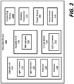
- FIG. 2 schematically illustrates the wearable device 100.
- the wearable device 100 includes an optical unit 120 that detects the first set of signals 12 for sensing SpO 2 and an acoustic unit 130 that detects the second set of signals 14 for sensing blood pressure.
- the optical unit 120 is a photoplethysmogram (PPG) sensor while the acoustic unit 130 is a phonocardiogram (PCG) sensor.
- the wearable device 100 includes both the optical unit 120 and acoustic unit 130 in a single assembly to provide a small, lightweight, and easy to integrate sensor package for measuring both SpO 2 and blood pressure.
- the wearable device 100 may include only the optical unit 120.
- the optical unit 120 includes one or more light emitters 122 to transmit optical signals to illuminate a portion of the body of the subject S, one or more light sensors 124 to receive optical signals reflected back from the illuminated portion of the body of the subject S, and first and second polarizers 126, 128 that are used to filter the reflected optical signals.
- the light emitters 122 emit optical signals in the form of infrared (IR) and visible red light.
- the light emitters 122 can be LEDs, lasers, lamps, and the like.
- the light emitters 122 include a pair of LEDs with one LED emitting visible red light with a wavelength of about 660 nm, and the other LED emitting infrared light with a wavelength of about 940 nm. Absorption of light at these wavelengths differs significantly between blood loaded with oxygen and blood lacking oxygen. Oxygenated hemoglobin absorbs more infrared light and allows more visible red light to pass through. Deoxygenated hemoglobin allows more infrared light to pass through and absorbs more visible red light. The pair of LEDs can sequence the transmission of the red and infrared light to allow the light sensors 124 to respond to the red and infrared light separately.
- the amount of absorption for each wavelength of light is measured.
- the ratio of the red light absorption to the infrared light absorption is calculated which represents the ratio of oxygenated hemoglobin to deoxygenated hemoglobin, and this ratio is converted to an SpO 2 measurement by using a lookup table.
- the amount of absorption for each wavelength of light can also be used to generate a plethysmograph and to evaluate blood perfusion.
- the light sensors 124 measure changes in the infra-red (IR) and red light absorption in the blood of the subject S where the wearable device 100 is attached.
- the light sensors 124 are photodetectors or photodiodes.
- the first and second polarizers 126, 128 are optical filters that let light waves of a specific polarization to pass through while blocking light waves that are not polarized.
- the first polarizer 126 polarizes the optical signals emitted from the light emitters 122 into a beam of polarized light
- the second polarizer 128 filters the optical signals reflected back from the body to reduce noise in the reflected optical signals received by the light sensors 124.
- the light emitters 122 are lasers
- the emitted light is already linearly polarized such that the first polarizer 126 is not needed in such a configuration.
- the optical unit 120 in addition to sensing SpO 2 , is also used to measure photoplethysmogram (PPG) signals of the subject S that can be used to detect blood volume changes in the subject S.
- PPG signals are obtained by using the optical unit 120 to illuminate a microvascular bed of tissue and measure changes in light absorption.
- the acoustic unit 130 includes a microphone 132 to record acoustic signals from the heart of the subject S during a cardiac cycle.
- the wearable device 100 is preferably attached to the chest of the subject S.
- the wearable device 100 is attached to a position of the chest adjacent to the sternum and in the second intercostal space between the ribs below the clavicle such that the microphone 132 is positioned next to the heart.
- the acoustic signals also referred to herein as PCG signals, detect heart sounds that result from vibrations caused by the closing of heart valves and are used for non-invasive blood pressure (NIBP) algorithms.
- NIBP non-invasive blood pressure
- the optical and acoustical signals obtained by the optical unit 120 and acoustic unit 130, respectively, can be used to calculate a pulse transit time (PTT) which is the time it takes a pulse pressure waveform to propagate through a length of an artery.
- PTT pulse transit time
- the PTT is the time delay of blood flow waveforms which closely correlates to blood pressure, and can be used to estimate both systolic and diastolic blood pressure.
- the PTT can be calculated from the detected blood volume changes which are determined from the optical signals obtained by the optical unit 120 and from the heart sounds obtained by the acoustic unit 130.
- the wearable device 100 includes a circuit board 140 to mechanically support and electrically connect the various electronic components of the wearable device 100.
- the circuit board 140 can include an analog to digital converter 142.
- the wearable device 100 further includes a computing device 1200 for processing the optical and acoustical signals from the optical unit 120 and acoustic unit 130, respectively.
- the computing device 1200 includes at least one processing unit and a memory.
- the memory stores algorithms that when performed by the processing unit calculate the SpO 2 and blood pressure of the subject S. Once calculated, a wireless transceiver 150 can transmit the SpO 2 and blood pressure values to the monitor device 200 for display on the display 204.
- the wireless transceiver 150 can transmit raw data (i.e., the optical and acoustical signals from the optical and acoustic units 120, 130) to the monitor device 200, and the monitor device 200 performs the algorithms to calculate the SpO 2 and blood pressure of the subject S, or the monitor device 200 forwards the raw data to the server 1300 and the server 1300 performs the algorithms to calculate the SpO 2 and blood pressure of the subject S.
- raw data i.e., the optical and acoustical signals from the optical and acoustic units 120, 130
- the monitor device 200 performs the algorithms to calculate the SpO 2 and blood pressure of the subject S
- the monitor device 200 forwards the raw data to the server 1300 and the server 1300 performs the algorithms to calculate the SpO 2 and blood pressure of the subject S.
- an algorithm stored in a memory of either the wearable device 100, monitor device 200, or server 1300 is used to calculate the SpO 2 of the subject S.
- the oxygenated and deoxygenated hemoglobin are detected by the optical unit 120 from the optical signals that are reflected back from the body and received by the light sensors 124.
- one or more algorithms stored in a memory of either the wearable device 100 or monitor device 200 are used to calculate the pulse transit time (PTT) from the PPG and PCG signals.
- PTT pulse transit time
- the PTT can be calculated as the time delay between the PCG and PPG waveforms.
- the PTT can be calculated as the time delay between proximal and distal PPG waveforms. Thereafter, the calculated PTT is used to estimate the systolic blood pressure and diastolic blood pressure of the subject S.
- the wearable device 100 further includes a power source 160 to power the various components of the wearable device 100 including the components of the optical unit 120 such as the light emitters 122 and light sensors 124 and the components of the acoustic unit 130 including the microphone 132.
- the power source 160 can include disposable or rechargeable batteries. Alternative power sources are possible.
- the wearable device 100 can include an attachment mechanism 170 to secure the wearable device 100 to the body of the subject S.
- attachment mechanisms 170 can be used.
- an adhesive can be used to secure the wearable device 100 to the body of the subject S.
- the wearable device 100 can be incorporated into a strap or clothing that can be tightly fitted around the body of the subject S such that the wearable device 100 is snuggly attached up against a body surface such as the chest wall of the subject S.
- the wearable device 100 can be included in an assembly that includes additional components and sensors.
- the wearable device 100 can be included in a patch worn by the subject S that includes additional sensors such as ECG electrodes, temperature sensors, and the like.
- the wearable device 100 is included in a patch that can noninvasively determine various vital signs such as body temperature, blood pressure, pulse (i.e., heart rate), and breathing rate.
- the wearable device 100 is included in a patch that calculate an early warning score based on the noninvasively determined vitals.
- FIG. 3 illustrates a housing 102 of the wearable device 100.
- FIG. 4 is a cross-sectional view of the housing 102.
- the housing 102 includes a rim 108 that defines an opening into an interior cavity 104.
- the rim 108 includes a surface 110 that is substantially planar.
- the surface 110 is in direct contact with a skin surface such as the chest wall so that the optical and acoustical signals from the optical unit 120 and acoustic unit 130, respectively, are able to penetrate the skin surface and reach the chest tissue of the subject S.
- the interior cavity 104 is funnel shaped.
- the interior cavity 104 has a concave profile that defines an apex at an end opposite the opening.
- the concave profile is symmetrical about a central axis 114 (see FIG. 3 ).
- the concave profile is parabolic such that the housing 102 is a parabolic reflector.
- the interior cavity 104 is a compound parabolic concentrator (CPC), an off-axis reflector, or a freeform surface.
- the interior cavity 104 can be asymmetrical with respect to the central axis 114.
- the opening of the interior cavity 104 can be about 1 inch to about 3 ⁇ 4 of one inch in diameter.
- the rim 108 is shown as having a substantially circular shape, a plurality of shapes for the rim 108 are possible.
- the circuit board 140 is mounted inside the housing 102 toward an apex of the interior cavity 104.
- the light emitters 122, light sensors 124, and microphone 132 are each mounted to the circuit board 140 toward the apex of the interior cavity 104.
- the light emitters 122 and light sensors 124 are mounted to a first side of the circuit board 140 and face the opening of the interior cavity 104, and the first and second polarizers 126, 128 are mounted over the light emitters 122 and light sensors 124. As shown in FIG.
- the first and second polarizers 126, 128 are mounted over the light emitters 122 and light sensors 124 such that the first and second polarizers 126, 128 are axially aligned about the central axis 114 of the interior cavity 104.
- the microphone 132 is mounted to an opposite, second side of the circuit board 140 that faces away from the opening of the interior cavity 104.
- the first and second polarizers 126, 128 each include an aperture 129 that allows the acoustic signals to pass through the first and second polarizers 126, 128.
- the circuit board 140 also includes an aperture 134 that is axially aligned with the apertures 129 of the first and second polarizers 126, 128.
- the aperture 134 together with the apertures 129 on the first and second polarizers 126, 128 forms a passageway that allows the acoustic signals to enter the interior cavity 104 of the housing 102 and reach the microphone 132 positioned at the apex of the interior cavity 104.
- the passageway formed by the apertures 129, 134 improves the transmission of the acoustic signals to the microphone 132.
- the concave surface profile of the interior cavity 104 funnels the acoustic signals from the opening of the interior cavity 104 to the microphone 132 located at the apex.
- the concave surface profile also funnels the reflected optical signals from the opening of the interior cavity 104 toward the light sensors 124 at the apex.
- the interior cavity 104 effectively collects and amplifies the acoustic and optical signals simultaneously.
- the interior cavity 104 has a reflective interior surface 106 that is applied over the concave surface profile.
- the housing 102 is molded plastic while the reflective interior surface 106 is a coating applied to the molded plastic using one or more coating techniques during the manufacture of the wearable device 100.
- the reflective interior surface 106 is electro-deposited nickel plating.
- the wearable device 100 is preferably attached to the chest so that the microphone 132 is positioned next to the heart.
- the light emitters 122 and light sensors 124 are positioned on the same side of the subject's body (i.e., the chest), and the optical signals emitted from the light emitters 122 are reflected off the chest tissue and back to the light sensors 124.
- the chest tissue is a poor site for blood perfusion and the reflected optical signals are weaker than the signals typically recorded by pulse oximeters.
- the shape of the interior cavity 104 and the reflective interior surface 106 are used to amplify the optical signals that are reflected off the chest tissue for reading by the light sensors 124 which are positioned at the apex of the interior cavity 104. Also, the shape of the interior cavity 104 is used to reduce the potential for ambient light interference.
- the reflected optical signals include noise from the light that is reflected directly off the skin surface covering the chest tissue (i.e., glare).
- the glare from the skin surface is noise because it does not provide useful data on the oxygenated and deoxygenated hemoglobin which is used for the calculation of the SpO 2 .
- the glare from the skin surface does not provide useful data for detecting blood volume changes for the calculation of the pulse transit time (PTT) and blood pressure.
- the first and second polarizers 126, 128 filter the optical signals received by the light sensors 124 so that only optical signals that penetrates deeper into the chest tissue are received by the light sensors 124 for calculation of SpO 2 and blood pressure which results in a more accurate device.
- FIG. 5 illustrates the light emitters 122 and light sensors 124 positioned around the circuit board 140, and with the first and second polarizers 126, 128 mounted over the light emitters 122 and the light sensors 124.
- the first and second polarizers 126, 128 polarize the optical signals emitted from the light emitters 122 and filter the reflected optical signals received by the light sensors 124.
- the first and second polarizers 126, 128 each include cutouts 127 that correspond to the shape, size, and location of the light emitters 122 and light sensors 124 on the circuit board 140.
- the first and second polarizers 126, 128 are linear polarizers that are both die cut from a single sheet of material that has a polarization running in one direction.
- the sheet of material from which the first and second polarizers 126, 128 are die cut is plastic.
- the first and second polarizers 126, 128 are glass or crystal.
- the first and second polarizers 126, 128 are circular-shaped discs mounted over the circuit board 140. In some examples, the circular-shaped discs each have an identical thickness of about 0.5 mm.
- the first polarizer 126 is mounted over the light emitters 122 and light sensors 124 while the second polarizer 128 is mounted over the first polarizer 126.
- the first and second polarizers 126, 128 are shifted 90 degrees with respect to one another such that the optical signals emitted by the light emitters 122 and received by the light sensors 124 are 90 degrees out of phase due to the polarization of the first and second polarizers 126, 128.
- the first and second polarizers 126, 128 each include one or more keys 131 to ensure that they are shifted 90 degrees with respect to one another when mounted over the light emitters 122 and light sensors 124.
- the keys 131 can include one or more notches on the first and second polarizers 126, 128 that correspond to one or more features on the housing 102 or circuit board 140 to ensure the polarizers are shifted 90 degrees with respect to one another.
- the cutouts 127 on the first polarizer 126 are positioned over the light sensors 124 such that the light emitters 122 are covered by the first polarizer 126 and the light sensors 124 are not covered by the first polarizer 126.
- the cutouts 127 on the second polarizer 128 are positioned over the light emitters 122 such that the light sensors 124 are covered by the second polarizer 128 and the light emitters 122 are not covered by the second polarizer 128.
- the cutouts 127 on the first polarizer 126 are positioned over the light emitters 122 so that the light sensors 124 are covered by the first polarizer 126 and the light emitters 122 are not covered by the first polarizer 126.
- the cutouts 127 on the second polarizer 128 are positioned over the light sensors 124 such that the light emitters 122 are covered by the second polarizer 128 and the light sensors 124 are not covered by the second polarizer 128.
- lines running in a first direction represent a first polarity direction and are superimposed over the light emitters 122 by the first polarizer 126.
- Lines running in a second direction represent a second polarity direction and are superimposed over the light sensors 124 by the second polarizer 128.
- the optical signals emitted from the light emitters 122 are polarized by the first polarizer 126 in the first polarity direction and the second polarizer 128 filters the reflected optical signals in the second polarity direction.
- the first and second polarizers 126, 128 are shifted 90 degrees such that the first and second polarity directions are orthogonal.
- FIG. 5 is provided as an illustrative example such that the first and second polarity directions of the first and second polarizers 126, 128, respectively, could be flipped with respect to one another.
- the first and second polarizers 126, 128 can be pieces of polarized material individually mounted over each light emitter 122 and light sensor124.
- the first polarizers 126 can be individually mounted over each light emitter 122 to have a first polarity direction while the second polarizers 128 can be individually mounted over each light sensor 124 to have a second polarity direction. Additional alternative embodiments are contemplated.
- the first and second polarizers 126, 128 operate to filter the reflected optical signals as follows.
- the optical signals reflected from the skin surface remain polarized in the first polarity direction. Since the second polarizer 128 is 90 degrees out of phase with respect to the first polarizer 126, the optical signals reflected from the skin surface are blocked from reaching the light sensors 124.
- the optical signals that penetrate into the chest tissue are no longer polarized in the first polarity direction such that these optical signals are able to pass through the second polarizer 128 and reach the light sensors 124.
- the glare from the skin surface is blocked from reaching the light sensors 124, while the optical signals that penetrate the chest tissue are received by the light sensors 124. This reduces noise in the optical signals received by the light sensors 124, and can thus lead to more accurate measurements.
- the first and second polarizers 126, 128 are circular polarizers.
- the first polarizer is configured to polarize the optical signals emitted from the light emitters 122 in a clockwise or counter-clockwise direction.
- the second polarizer 128 is configured to have a circular polarity direction opposite that of the first polarizer 126 such that the second polarizer 128 blocks the optical signals reflected from the skin surface that remain polarized in the clockwise or counter-clockwise direction set by the first polarizer 126.
- the light emitters 122 emit polarized light.
- the light emitters 122 can be lasers that emit polarized light.
- the polarized light emitted from light emitters 122 is linearly polarized light.
- there is no need for a second polarizer such that the optical unit 120 uses only one polarizer.
- the optical unit 120 has at least one polarizer 126, 128, and the polarized light emitted from the light emitters 122 that is reflected off a skin surface is filtered by the at least one polarizer 126, 128.
- the optical signals reflected from the skin surface remain polarized in the direction of the polarized light.
- the at least one polarizer 126, 128 is orientated to block optical signals having a predetermined polarity direction such as the polarity direction of the polarized light from the light emitters 122.
- the optical signals reflected from the skin surface are blocked by the at least one polarizer 126, 128 from reaching the one or more light sensors 124, while the optical signals that penetrate into the chest tissue are no longer polarized in the direction of the polarized light such that these optical signals pass through the at least one polarizer 126, 128 and reach the one or more light sensors 124.
- FIG. 6 illustrates a method 600 for obtaining vital signs that is performed by the wearable device 100.
- the method 600 includes an operation 602 of emitting optical signals using the light emitters 122.
- the method 600 includes an operation 604 of polarizing the emitted optical signals in a first direction by using the first polarizer 126.
- Method 600 includes an operation 606 of filtering the reflected optical signals by using the second polarizer 128 to block the reflected optical signals that do not penetrate into a tissue.
- method 600 includes an operation 608 of using the light sensors 124 to receive reflected optical signals that penetrate into the tissue.
- the tissue is a chest tissue located next to the heart of the subject S.
- the method can further include using the reflected optical signals that penetrate into the tissue to measure a vital sign.
- the reflected optical signals can be used to calculate peripheral oxygen saturation.
- the reflected optical signals can be used to calculate blood pressure.
- FIG. 7 illustrates an exemplary architecture of a computing device 1200 which can be used to implement aspects of the present disclosure such as the functions of the wearable device 100 and monitor device 200 described above.
- the computing device 1200 includes a processing unit 1202, a system memory 1208, and a system bus 1220 that couples the system memory 1208 to the processing unit 1202.
- the processing unit 1202 is an example of a processing device such as a central processing unit (CPU).
- the system memory 1208 includes a random access memory (“RAM”) 1210 and a read-only memory (“ROM”) 1212.
- RAM random access memory
- ROM read-only memory
- the computing device 1200 can also include a mass storage device 1214 that is able to store software instructions and data.
- the mass storage device 1214 is connected to the processing unit 1202 through a mass storage controller (not shown) connected to the system bus 1220.
- the mass storage device 1214 and its associated computer-readable data storage media provide non-volatile, non-transitory storage for the computing device 1200.
- computer-readable data storage media can be any available non-transitory, physical device or article of manufacture from which the device can read data and/or instructions.
- the mass storage device 1214 is an example of a computer-readable storage device.
- Computer-readable data storage media include volatile and non-volatile, removable and non-removable media implemented in any method or technology for storage of information such as computer-readable software instructions, data structures, program modules or other data.
- Example types of computer-readable data storage media include, but are not limited to, RAM, ROM, EPROM, EEPROM, flash memory or other solid state memory technology, or any other medium which can be used to store information and which can be accessed by the device.
- the computing device 1200 may operate in a networked environment using logical connections to remote network devices through the network 250, such as a local network, the Internet, or another type of network.
- the device connects to the network 250 through a network interface unit 1204 connected to the system bus 1220.
- the network interface unit 1204 may also be utilized to connect to other types of networks and remote computing systems.
- the computing device 1200 can also include an input/output controller 1206 for receiving and processing input from a number of input devices. Similarly, the input/output controller 1206 may provide output to a number of output devices.
- the mass storage device 1214 and the RAM 1210 can store software instructions and data.
- the software instructions can include an operating system 1218 suitable for controlling the operation of the device.
- the mass storage device 1214 and/or the RAM 1210 also store software instructions 1216, that when executed by the processing unit 1202, cause the device to provide the functionality of the device discussed in this document.
- the mass storage device 1214 and/or the RAM 1210 can store software instructions that, when executed by the processing unit 1202, cause the wearable device to send or receive vital signs measurements.
Landscapes
- Health & Medical Sciences (AREA)
- Life Sciences & Earth Sciences (AREA)
- Physics & Mathematics (AREA)
- Engineering & Computer Science (AREA)
- Public Health (AREA)
- Veterinary Medicine (AREA)
- General Health & Medical Sciences (AREA)
- Animal Behavior & Ethology (AREA)
- Biomedical Technology (AREA)
- Heart & Thoracic Surgery (AREA)
- Medical Informatics (AREA)
- Molecular Biology (AREA)
- Surgery (AREA)
- Pathology (AREA)
- Cardiology (AREA)
- Biophysics (AREA)
- Physiology (AREA)
- Acoustics & Sound (AREA)
- Optics & Photonics (AREA)
- Spectroscopy & Molecular Physics (AREA)
- Vascular Medicine (AREA)
- Psychiatry (AREA)
- Signal Processing (AREA)
- Pulmonology (AREA)
- Computer Vision & Pattern Recognition (AREA)
- Artificial Intelligence (AREA)
- Measurement Of The Respiration, Hearing Ability, Form, And Blood Characteristics Of Living Organisms (AREA)
Abstract
A wearable device for sensing vital signs includes a housing defining an interior cavity. An optical unit is positioned inside the interior cavity. The optical unit includes one or more light emitters that emit optical signals, at least one polarizer orientated to block optical signals having a predetermined polarity direction, and one or more light sensors that receive optical signals that pass through the at least one polarizer. An acoustic unit is positioned inside the interior cavity, and has a microphone to receive acoustic signals that enter into the interior cavity. The acoustic signals are used to non-invasively estimate blood pressure.
Description
- Vital sign measurements are taken to help assess the general physical health of a subject, give clues to possible diseases, and show progress toward recovery. One type of vital sign that is often measured is blood oxygen saturation which is the fraction of oxygen-saturated hemoglobin relative to total hemoglobin in the blood of the subject. Normal blood oxygen saturation levels in humans are 95-100 percent. Blood oxygen saturation levels below 90 percent are considered deficient and are diagnosed as hypoxemia. Blood oxygen saturation levels below 80 percent may compromise organ function, such as the brain and heart, and should be promptly addressed. Continued low oxygen levels may lead to respiratory or cardiac arrest.
- Another vital sign that is often measured is blood pressure which is the pressure of circulating blood on the walls of blood vessels. Blood pressure results from the heart pumping blood through the circulatory system and is usually expressed in terms of the systolic pressure (maximum pressure during one heartbeat) over diastolic pressure (minimum pressure in between two heartbeats). Blood pressure is typically measured using an inflatable cuff to collapse and then release the artery under the cuff in a controlled manner to measure the pressure.
- In general terms, the present disclosure relates to a wearable device for sensing vital signs. In one possible configuration, the wearable device provides a technical effect by sensing the blood oxygen saturation level of a subject when attached to a portion of the subject's body that has low blood perfusion and that is ordinarily unable to provide useful data for measuring blood oxygen saturation. In yet another possible configuration, the wearable device provides a technical effect by measuring both the blood oxygen saturation and blood pressure of the subject simultaneously when attached to a portion of the subject's body. Various aspects are described in this disclosure, which include, but are not limited to, the following aspects.
- In one aspect, a wearable device for sensing vital signs comprises: a housing defining an interior cavity; an optical unit positioned inside the interior cavity, the optical unit having: one or more light emitters that emit optical signals; at least one polarizer orientated to block optical signals having a predetermined polarity direction; and one or more light sensors that receive optical signals that pass through the at least one polarizer; and an acoustic unit positioned inside the interior cavity, the acoustic unit having: a microphone to receive acoustic signals that enter into the interior cavity, the acoustic signals being used to non-invasively estimate blood pressure.
- In another aspect, a wearable device for sensing vital signs comprises: a housing defining an interior cavity; an optical unit positioned inside the interior cavity, the optical unit having: one or more light emitters that emit optical signals; a first polarizer orientated to polarize the optical signals emitted from the one or more light emitters in a first polarity direction; a second polarizer orientated with respect to the second polarizer to block optical signals reflected in the first polarity direction; and one or more light sensors that receive reflected optical signals that pass through the second polarizer, the reflected optical signals being used to non-invasively measure peripheral oxygen saturation.
- In another aspect, a method for obtaining vital signs comprises: emitting polarized optical signals; filtering optical signals that do not penetrate into a tissue; receiving the filtered optical signals; and using the filtered optical signals to measure a vital sign.
- The invention will now be further described by way of example with reference to the accompanying drawings, in which:
-
FIG. 1 schematically illustrates a patient monitoring system. -
FIG. 2 schematically illustrates a wearable device for sensing vital signs. -
FIG. 3 illustrates a housing of the wearable device. -
FIG. 4 is a cross-sectional view of the housing. -
FIG. 5 illustrates an array of light emitters and light sensors. -
FIG. 6 illustrates a method for filtering reflected optical signals. -
FIG. 7 illustrates an exemplary architecture of a computing device that can be used to implement aspects of the present disclosure. -
FIG. 1 is a schematic view of apatient monitoring system 10 that includes awearable device 100 that can be worn by a subject S to measure one or more vital signs. Thewearable device 100 is "wearable" in that it can be applied to a subject's skin and will resist unintentional dislodgement over a specified interval of time - In one embodiment, the
wearable device 100 is used to measure peripheral oxygen saturation (SpO2) of the subject S by calculating a difference in absorption between oxygenated and deoxygenated hemoglobin in the blood of the subject S. In this embodiment, thewearable device 100 can be attached to any area of the body of the subject S including the chest to detect a first set ofsignals 12 for sensing SpO2. Thewearable device 100 amplifies and removes noise from the first set ofsignals 12 to improve the quality of the SpO2 measurements. - In another embodiment, the
wearable device 100 is used to measure both the SpO2 and blood pressure of the subject S by detecting the first set ofsignals 12 for sensing SpO2 and detecting a second set ofsignals 14 for sensing blood pressure. Advantageously, thewearable device 100 can be used to non-invasively measure blood pressure without using an inflatable cuff. Instead, thewearable device 100 is attached to the chest of the subject S. Thewearable device 100 simultaneously detects the first and second sets ofsignals wearable device 100 both amplifies the first and second sets ofsignals - As shown in
FIG. 1 , thewearable device 100 transmits the first and second sets ofsignals monitor device 200. In one embodiment, themonitor device 200 is a smartphone, tablet computer, or other portable computing device. In another embodiment, the display device is a vital signs monitor that can be fixed to a wall or to another device within a facility such as a bed, or is a portable spot monitor that can be moved about the facility. - The first and second sets of
signals wireless transceiver 202 of themonitor device 200 such that thewearable device 100 is not tethered to themonitor device 200. Advantageously, the wireless transmission allows the subject S to move freely relative to themonitor device 200 and thereby enhances the mobility of the subject S while thewearable device 100 is worn by the subject S. Examples of the wireless transmission between thewearable device 100 and themonitor device 200 can include, without limitation, Bluetooth, Wi-Fi, RFID, Near-Field Communication (NFC), ZigBee, and the like. - In one embodiment, the first and second sets of
signals monitor device 200 to determine the SpO2 and blood pressure measurements. Themonitor device 200 includes acomputing device 1200 for processing the first and second sets ofsignals computing device 1200 includes at least one processing unit and a memory (which are described in more detail below with reference toFIG. 7 ). The memory of thecomputing device 1200 stores one or more algorithms that are performed by the processing unit of thecomputing device 1200 to calculate the SpO2 and blood pressure measurements. - In another embodiment, the
patient monitoring system 10 includes aserver 1300 that is remotely located with respect to thewearable device 100 andmonitor device 200. In this embodiment, themonitor device 200 transmits the first and second sets ofsignals server 1300 via anetwork 250, and theserver 1300 uses acomputing device 1200 to process the first and second sets ofsignals monitor device 200 and/orwearable device 100 via thenetwork 250. - The
network 250 can include any type of wired or wireless connections or any combinations thereof. Examples of wireless connections include digital cellular network connections such as 5G. In some embodiments, wireless connections can be accomplished using Bluetooth, Wi-Fi, RFID, NFC, ZigBee, and the like. - In another embodiment, the
wearable device 100 processes the raw data itself to determine the SpO2 and blood pressure measurements such that the first and second sets ofsignals wearable device 100 include a computing device that includes at least one processing unit and a memory (e.g., such as those described below with reference toFIG. 7 ). - In further embodiments, the processing of the raw data to determine the SpO2 and blood pressure measurements is shared between the
wearable device 100, themonitor device 200, and/or theserver 1300, and may vary depending on one or more system parameters including, but not limited to, the processing capacities of the respective devices, the battery levels of the respective devices, energy cost of transmitting the first and second sets ofsignals signals - The
monitor device 200 includes adisplay 204 for displaying the determined SpO2 and blood pressure measurements of the subject S. In some examples, thedisplay 204 displays the determined SpO2 and blood pressure measurements numerically, graphically, or in a combination of numerical and graphical representations. In some examples, the determined SpO2 and blood pressure measurements are displayed on thewearable device 100 while worn by the subject S in addition or as an alternative to being displayed on thedisplay 204. - The
monitor device 200 further includes analarm unit 206. Thealarm unit 206 generates one or more alarms when the determined SpO2 and blood pressure measurements are outside a predetermined limit. In some examples, thealarm unit 206 generates visual alarms on thedisplay 204, audible alarms, and the like. In some further examples, in addition to or as an alternative to generating visual and/or audible alarms, thealarm unit 206 generates a message sent directly to one or more caregivers to notify the caregivers that the determined SpO2 and blood pressure measurements are outside a predetermined limit. Examples of such messages can include text messages, instant messages, emails, and the like. - The
monitor device 200 is in communication with thenetwork 250 for transmitting the determined SpO2 and blood pressure measurements to an electronic medical record system 260 (alternatively termed electronic health record, EMR/EHR). The determined SpO2 and blood pressure measurements can be stored in an electronic medical record or electronic health record associated with the subject S. -
FIG. 2 schematically illustrates thewearable device 100. As shown inFIG. 2 , thewearable device 100 includes anoptical unit 120 that detects the first set ofsignals 12 for sensing SpO2 and an acoustic unit 130 that detects the second set ofsignals 14 for sensing blood pressure. In some examples, theoptical unit 120 is a photoplethysmogram (PPG) sensor while the acoustic unit 130 is a phonocardiogram (PCG) sensor. Preferably, thewearable device 100 includes both theoptical unit 120 and acoustic unit 130 in a single assembly to provide a small, lightweight, and easy to integrate sensor package for measuring both SpO2 and blood pressure. In alternative examples thewearable device 100 may include only theoptical unit 120. - The
optical unit 120 includes one or morelight emitters 122 to transmit optical signals to illuminate a portion of the body of the subject S, one or morelight sensors 124 to receive optical signals reflected back from the illuminated portion of the body of the subject S, and first andsecond polarizers - The
light emitters 122 emit optical signals in the form of infrared (IR) and visible red light. Thelight emitters 122 can be LEDs, lasers, lamps, and the like. - In one embodiment, the
light emitters 122 include a pair of LEDs with one LED emitting visible red light with a wavelength of about 660 nm, and the other LED emitting infrared light with a wavelength of about 940 nm. Absorption of light at these wavelengths differs significantly between blood loaded with oxygen and blood lacking oxygen. Oxygenated hemoglobin absorbs more infrared light and allows more visible red light to pass through. Deoxygenated hemoglobin allows more infrared light to pass through and absorbs more visible red light. The pair of LEDs can sequence the transmission of the red and infrared light to allow thelight sensors 124 to respond to the red and infrared light separately. - The amount of absorption for each wavelength of light is measured. The ratio of the red light absorption to the infrared light absorption is calculated which represents the ratio of oxygenated hemoglobin to deoxygenated hemoglobin, and this ratio is converted to an SpO2 measurement by using a lookup table. The amount of absorption for each wavelength of light can also be used to generate a plethysmograph and to evaluate blood perfusion.
- The
light sensors 124 measure changes in the infra-red (IR) and red light absorption in the blood of the subject S where thewearable device 100 is attached. In some examples, thelight sensors 124 are photodetectors or photodiodes. - The first and
second polarizers first polarizer 126 polarizes the optical signals emitted from thelight emitters 122 into a beam of polarized light, and thesecond polarizer 128 filters the optical signals reflected back from the body to reduce noise in the reflected optical signals received by thelight sensors 124. In embodiments where thelight emitters 122 are lasers, the emitted light is already linearly polarized such that thefirst polarizer 126 is not needed in such a configuration. - In some embodiments, in addition to sensing SpO2, the
optical unit 120 is also used to measure photoplethysmogram (PPG) signals of the subject S that can be used to detect blood volume changes in the subject S. The PPG signals are obtained by using theoptical unit 120 to illuminate a microvascular bed of tissue and measure changes in light absorption. - The acoustic unit 130 includes a
microphone 132 to record acoustic signals from the heart of the subject S during a cardiac cycle. In embodiments where thewearable device 100 includes the acoustic unit 130, thewearable device 100 is preferably attached to the chest of the subject S. In some examples, thewearable device 100 is attached to a position of the chest adjacent to the sternum and in the second intercostal space between the ribs below the clavicle such that themicrophone 132 is positioned next to the heart. The acoustic signals, also referred to herein as PCG signals, detect heart sounds that result from vibrations caused by the closing of heart valves and are used for non-invasive blood pressure (NIBP) algorithms. - In some embodiments, the optical and acoustical signals obtained by the
optical unit 120 and acoustic unit 130, respectively, can be used to calculate a pulse transit time (PTT) which is the time it takes a pulse pressure waveform to propagate through a length of an artery. The PTT is the time delay of blood flow waveforms which closely correlates to blood pressure, and can be used to estimate both systolic and diastolic blood pressure. The PTT can be calculated from the detected blood volume changes which are determined from the optical signals obtained by theoptical unit 120 and from the heart sounds obtained by the acoustic unit 130. - Still referring to
FIG. 2 , thewearable device 100 includes acircuit board 140 to mechanically support and electrically connect the various electronic components of thewearable device 100. Thecircuit board 140 can include an analog todigital converter 142. - The
wearable device 100 further includes acomputing device 1200 for processing the optical and acoustical signals from theoptical unit 120 and acoustic unit 130, respectively. Thecomputing device 1200 includes at least one processing unit and a memory. In some embodiments, the memory stores algorithms that when performed by the processing unit calculate the SpO2 and blood pressure of the subject S. Once calculated, awireless transceiver 150 can transmit the SpO2 and blood pressure values to themonitor device 200 for display on thedisplay 204. Alternatively, thewireless transceiver 150 can transmit raw data (i.e., the optical and acoustical signals from the optical andacoustic units 120, 130) to themonitor device 200, and themonitor device 200 performs the algorithms to calculate the SpO2 and blood pressure of the subject S, or themonitor device 200 forwards the raw data to theserver 1300 and theserver 1300 performs the algorithms to calculate the SpO2 and blood pressure of the subject S. - With respect to SpO2, an algorithm stored in a memory of either the
wearable device 100,monitor device 200, orserver 1300 is used to calculate the SpO2 of the subject S. As an example, an algorithm to calculate the SpO2 of the subject S can be expressed as follows:
optical unit 120 from the optical signals that are reflected back from the body and received by thelight sensors 124. - With respect to blood pressure, one or more algorithms stored in a memory of either the
wearable device 100 or monitordevice 200 are used to calculate the pulse transit time (PTT) from the PPG and PCG signals. For example, the PTT can be calculated as the time delay between the PCG and PPG waveforms. Alternatively, the PTT can be calculated as the time delay between proximal and distal PPG waveforms. Thereafter, the calculated PTT is used to estimate the systolic blood pressure and diastolic blood pressure of the subject S. - The
wearable device 100 further includes apower source 160 to power the various components of thewearable device 100 including the components of theoptical unit 120 such as thelight emitters 122 andlight sensors 124 and the components of the acoustic unit 130 including themicrophone 132. As an example, thepower source 160 can include disposable or rechargeable batteries. Alternative power sources are possible. - The
wearable device 100 can include anattachment mechanism 170 to secure thewearable device 100 to the body of the subject S. A variety ofattachment mechanisms 170 can be used. For example, an adhesive can be used to secure thewearable device 100 to the body of the subject S. Alternatively, thewearable device 100 can be incorporated into a strap or clothing that can be tightly fitted around the body of the subject S such that thewearable device 100 is snuggly attached up against a body surface such as the chest wall of the subject S. - The
wearable device 100 can be included in an assembly that includes additional components and sensors. For example, thewearable device 100 can be included in a patch worn by the subject S that includes additional sensors such as ECG electrodes, temperature sensors, and the like. In some embodiments, thewearable device 100 is included in a patch that can noninvasively determine various vital signs such as body temperature, blood pressure, pulse (i.e., heart rate), and breathing rate. In some further embodiments, thewearable device 100 is included in a patch that calculate an early warning score based on the noninvasively determined vitals. -
FIG. 3 illustrates ahousing 102 of thewearable device 100.FIG. 4 is a cross-sectional view of thehousing 102. Referring now toFIGS. 3 and4 , thehousing 102 includes arim 108 that defines an opening into aninterior cavity 104. Therim 108 includes asurface 110 that is substantially planar. When thewearable device 100 is worn by the subject S, thesurface 110 is in direct contact with a skin surface such as the chest wall so that the optical and acoustical signals from theoptical unit 120 and acoustic unit 130, respectively, are able to penetrate the skin surface and reach the chest tissue of the subject S. - The
interior cavity 104 is funnel shaped. In some examples, theinterior cavity 104 has a concave profile that defines an apex at an end opposite the opening. In some examples, the concave profile is symmetrical about a central axis 114 (seeFIG. 3 ). In some examples, the concave profile is parabolic such that thehousing 102 is a parabolic reflector. In yet further examples, theinterior cavity 104 is a compound parabolic concentrator (CPC), an off-axis reflector, or a freeform surface. In alternative examples, theinterior cavity 104 can be asymmetrical with respect to thecentral axis 114. - In some examples, the opening of the
interior cavity 104 can be about 1 inch to about ¾ of one inch in diameter. Additionally, while therim 108 is shown as having a substantially circular shape, a plurality of shapes for therim 108 are possible. - As shown in
FIG. 4 , thecircuit board 140 is mounted inside thehousing 102 toward an apex of theinterior cavity 104. Thelight emitters 122,light sensors 124, andmicrophone 132 are each mounted to thecircuit board 140 toward the apex of theinterior cavity 104. Thelight emitters 122 andlight sensors 124 are mounted to a first side of thecircuit board 140 and face the opening of theinterior cavity 104, and the first andsecond polarizers light emitters 122 andlight sensors 124. As shown inFIG. 3 , the first andsecond polarizers light emitters 122 andlight sensors 124 such that the first andsecond polarizers central axis 114 of theinterior cavity 104. Themicrophone 132 is mounted to an opposite, second side of thecircuit board 140 that faces away from the opening of theinterior cavity 104. - As shown in
FIG. 3 , the first andsecond polarizers aperture 129 that allows the acoustic signals to pass through the first andsecond polarizers FIG. 4 , thecircuit board 140 also includes anaperture 134 that is axially aligned with theapertures 129 of the first andsecond polarizers aperture 134 together with theapertures 129 on the first andsecond polarizers interior cavity 104 of thehousing 102 and reach themicrophone 132 positioned at the apex of theinterior cavity 104. Advantageously, the passageway formed by theapertures microphone 132. - The concave surface profile of the
interior cavity 104 funnels the acoustic signals from the opening of theinterior cavity 104 to themicrophone 132 located at the apex. The concave surface profile also funnels the reflected optical signals from the opening of theinterior cavity 104 toward thelight sensors 124 at the apex. Thus, theinterior cavity 104 effectively collects and amplifies the acoustic and optical signals simultaneously. - To further enhance the funneling of the optical signals reflected toward the
light sensors 124, theinterior cavity 104 has a reflectiveinterior surface 106 that is applied over the concave surface profile. Thehousing 102 is molded plastic while the reflectiveinterior surface 106 is a coating applied to the molded plastic using one or more coating techniques during the manufacture of thewearable device 100. In some embodiments, the reflectiveinterior surface 106 is electro-deposited nickel plating. - As described above, the
wearable device 100 is preferably attached to the chest so that themicrophone 132 is positioned next to the heart. Thus, unlike pulse oximeters that are clipped onto a fingertip to emit light signals that pass through the fingertip, thelight emitters 122 andlight sensors 124 are positioned on the same side of the subject's body (i.e., the chest), and the optical signals emitted from thelight emitters 122 are reflected off the chest tissue and back to thelight sensors 124. The chest tissue is a poor site for blood perfusion and the reflected optical signals are weaker than the signals typically recorded by pulse oximeters. To overcome these obstacles, the shape of theinterior cavity 104 and the reflectiveinterior surface 106 are used to amplify the optical signals that are reflected off the chest tissue for reading by thelight sensors 124 which are positioned at the apex of theinterior cavity 104. Also, the shape of theinterior cavity 104 is used to reduce the potential for ambient light interference. - Additionally, the reflected optical signals include noise from the light that is reflected directly off the skin surface covering the chest tissue (i.e., glare). The glare from the skin surface is noise because it does not provide useful data on the oxygenated and deoxygenated hemoglobin which is used for the calculation of the SpO2. Also, the glare from the skin surface does not provide useful data for detecting blood volume changes for the calculation of the pulse transit time (PTT) and blood pressure. To reduce this noise, the first and
second polarizers light sensors 124 so that only optical signals that penetrates deeper into the chest tissue are received by thelight sensors 124 for calculation of SpO2 and blood pressure which results in a more accurate device. -
FIG. 5 illustrates thelight emitters 122 andlight sensors 124 positioned around thecircuit board 140, and with the first andsecond polarizers light emitters 122 and thelight sensors 124. Referring now toFIGS. 3-5 , the first andsecond polarizers light emitters 122 and filter the reflected optical signals received by thelight sensors 124. As shown inFIG. 3 , the first andsecond polarizers cutouts 127 that correspond to the shape, size, and location of thelight emitters 122 andlight sensors 124 on thecircuit board 140. - In one embodiment, the first and
second polarizers second polarizers second polarizers second polarizers circuit board 140. In some examples, the circular-shaped discs each have an identical thickness of about 0.5 mm. - The
first polarizer 126 is mounted over thelight emitters 122 andlight sensors 124 while thesecond polarizer 128 is mounted over thefirst polarizer 126. The first andsecond polarizers light emitters 122 and received by thelight sensors 124 are 90 degrees out of phase due to the polarization of the first andsecond polarizers - The first and
second polarizers more keys 131 to ensure that they are shifted 90 degrees with respect to one another when mounted over thelight emitters 122 andlight sensors 124. For example, thekeys 131 can include one or more notches on the first andsecond polarizers housing 102 orcircuit board 140 to ensure the polarizers are shifted 90 degrees with respect to one another. - In one example, the
cutouts 127 on thefirst polarizer 126 are positioned over thelight sensors 124 such that thelight emitters 122 are covered by thefirst polarizer 126 and thelight sensors 124 are not covered by thefirst polarizer 126. Thecutouts 127 on thesecond polarizer 128 are positioned over thelight emitters 122 such that thelight sensors 124 are covered by thesecond polarizer 128 and thelight emitters 122 are not covered by thesecond polarizer 128. - In another example, the
cutouts 127 on thefirst polarizer 126 are positioned over thelight emitters 122 so that thelight sensors 124 are covered by thefirst polarizer 126 and thelight emitters 122 are not covered by thefirst polarizer 126. Thecutouts 127 on thesecond polarizer 128 are positioned over thelight sensors 124 such that thelight emitters 122 are covered by thesecond polarizer 128 and thelight sensors 124 are not covered by thesecond polarizer 128. - As shown in
FIG. 5 , lines running in a first direction (e.g., horizontal) represent a first polarity direction and are superimposed over thelight emitters 122 by thefirst polarizer 126. Lines running in a second direction (e.g., vertical) represent a second polarity direction and are superimposed over thelight sensors 124 by thesecond polarizer 128. Thus, the optical signals emitted from thelight emitters 122 are polarized by thefirst polarizer 126 in the first polarity direction and thesecond polarizer 128 filters the reflected optical signals in the second polarity direction. As described above, the first andsecond polarizers FIG. 5 is provided as an illustrative example such that the first and second polarity directions of the first andsecond polarizers - As an alternative embodiment, instead of the disc shaped polarizers shown in
FIGS. 3-5 , the first andsecond polarizers light emitter 122 and light sensor124. For example, thefirst polarizers 126 can be individually mounted over eachlight emitter 122 to have a first polarity direction while thesecond polarizers 128 can be individually mounted over eachlight sensor 124 to have a second polarity direction. Additional alternative embodiments are contemplated. - The first and
second polarizers second polarizer 128 is 90 degrees out of phase with respect to thefirst polarizer 126, the optical signals reflected from the skin surface are blocked from reaching thelight sensors 124. In contrast, the optical signals that penetrate into the chest tissue are no longer polarized in the first polarity direction such that these optical signals are able to pass through thesecond polarizer 128 and reach thelight sensors 124. Thus, the glare from the skin surface is blocked from reaching thelight sensors 124, while the optical signals that penetrate the chest tissue are received by thelight sensors 124. This reduces noise in the optical signals received by thelight sensors 124, and can thus lead to more accurate measurements. - In alternative embodiments, the first and
second polarizers second polarizers light emitters 122 in a clockwise or counter-clockwise direction. Thesecond polarizer 128 is configured to have a circular polarity direction opposite that of thefirst polarizer 126 such that thesecond polarizer 128 blocks the optical signals reflected from the skin surface that remain polarized in the clockwise or counter-clockwise direction set by thefirst polarizer 126. - In alternative examples, the
light emitters 122 emit polarized light. For example, thelight emitters 122 can be lasers that emit polarized light. In certain examples, the polarized light emitted fromlight emitters 122 is linearly polarized light. In such examples, there is no need for a second polarizer such that theoptical unit 120 uses only one polarizer. In such examples, theoptical unit 120 has at least onepolarizer light emitters 122 that is reflected off a skin surface is filtered by the at least onepolarizer - For example, the optical signals reflected from the skin surface remain polarized in the direction of the polarized light. In such examples, the at least one
polarizer light emitters 122. Thus, the optical signals reflected from the skin surface are blocked by the at least onepolarizer light sensors 124, while the optical signals that penetrate into the chest tissue are no longer polarized in the direction of the polarized light such that these optical signals pass through the at least onepolarizer light sensors 124. -
FIG. 6 illustrates amethod 600 for obtaining vital signs that is performed by thewearable device 100. Themethod 600 includes anoperation 602 of emitting optical signals using thelight emitters 122. Next, themethod 600 includes anoperation 604 of polarizing the emitted optical signals in a first direction by using thefirst polarizer 126.Method 600 includes anoperation 606 of filtering the reflected optical signals by using thesecond polarizer 128 to block the reflected optical signals that do not penetrate into a tissue. Next,method 600 includes anoperation 608 of using thelight sensors 124 to receive reflected optical signals that penetrate into the tissue. In some examples, the tissue is a chest tissue located next to the heart of the subject S. - The method can further include using the reflected optical signals that penetrate into the tissue to measure a vital sign. For example, the reflected optical signals can be used to calculate peripheral oxygen saturation. Alternatively, or in addition to calculating the peripheral oxygen saturation, the reflected optical signals can be used to calculate blood pressure.
-
FIG. 7 illustrates an exemplary architecture of acomputing device 1200 which can be used to implement aspects of the present disclosure such as the functions of thewearable device 100 and monitordevice 200 described above. Thecomputing device 1200 includes aprocessing unit 1202, asystem memory 1208, and asystem bus 1220 that couples thesystem memory 1208 to theprocessing unit 1202. Theprocessing unit 1202 is an example of a processing device such as a central processing unit (CPU). Thesystem memory 1208 includes a random access memory ("RAM") 1210 and a read-only memory ("ROM") 1212. A basic input/output logic containing the basic routines that help to transfer information between elements within thecomputing device 1200, such as during startup, is stored in theROM 1212. - The
computing device 1200 can also include amass storage device 1214 that is able to store software instructions and data. Themass storage device 1214 is connected to theprocessing unit 1202 through a mass storage controller (not shown) connected to thesystem bus 1220. Themass storage device 1214 and its associated computer-readable data storage media provide non-volatile, non-transitory storage for thecomputing device 1200. - Although the description of computer-readable data storage media contained herein refers to a mass storage device, it should be appreciated by those skilled in the art that computer-readable data storage media can be any available non-transitory, physical device or article of manufacture from which the device can read data and/or instructions. The
mass storage device 1214 is an example of a computer-readable storage device. - Computer-readable data storage media include volatile and non-volatile, removable and non-removable media implemented in any method or technology for storage of information such as computer-readable software instructions, data structures, program modules or other data. Example types of computer-readable data storage media include, but are not limited to, RAM, ROM, EPROM, EEPROM, flash memory or other solid state memory technology, or any other medium which can be used to store information and which can be accessed by the device.
- The
computing device 1200 may operate in a networked environment using logical connections to remote network devices through thenetwork 250, such as a local network, the Internet, or another type of network. The device connects to thenetwork 250 through anetwork interface unit 1204 connected to thesystem bus 1220. Thenetwork interface unit 1204 may also be utilized to connect to other types of networks and remote computing systems. - The
computing device 1200 can also include an input/output controller 1206 for receiving and processing input from a number of input devices. Similarly, the input/output controller 1206 may provide output to a number of output devices. - The
mass storage device 1214 and the RAM 1210 can store software instructions and data. The software instructions can include anoperating system 1218 suitable for controlling the operation of the device. Themass storage device 1214 and/or the RAM 1210 also storesoftware instructions 1216, that when executed by theprocessing unit 1202, cause the device to provide the functionality of the device discussed in this document. For example, themass storage device 1214 and/or the RAM 1210 can store software instructions that, when executed by theprocessing unit 1202, cause the wearable device to send or receive vital signs measurements. - The various embodiments described above are provided by way of illustration only and should not be construed to be limiting in any way. Various modifications can be made to the embodiments described above.
- Embodiments of the invention can be described with reference to the following numbered clauses, with preferred features laid out in the dependent clauses:
- 1. A wearable device for sensing vital signs comprising:
- a housing defining an interior cavity;
- an optical unit positioned inside the interior cavity, the optical unit having:
- one or more light emitters that emit optical signals;
- a first polarizer orientated to polarize the optical signals emitted from the one or more light emitters in a first polarity direction;
- a second polarizer orientated with respect to the second polarizer to block optical signals reflected in the first polarity direction; and
- one or more light sensors that receive reflected optical signals that pass through the second polarizer, the reflected optical signals being used to non-invasively measure peripheral oxygen saturation.
- 2. The wearable device of clause 1, further comprising an acoustic unit positioned inside the interior cavity, the acoustic unit having a microphone to receive acoustic signals that enter into the interior cavity, the acoustic signals being used to non-invasively estimate blood pressure.
- 3. A method for obtaining vital signs, comprising:
- emitting polarized optical signals;
- filtering optical signals that do not penetrate into a tissue;
- receiving the filtered optical signals; and
- using the filtered optical signals to measure a vital sign.
- 4. The method of clause 3, where the vital sign is peripheral oxygen saturation.
- 5. The method of either clause 3 or clause 4, where the vital sign is blood pressure.
Claims (15)
- A wearable device for sensing vital signs comprising:a housing defining an interior cavity;an optical unit positioned inside the interior cavity, the optical unit having:one or more light emitters that emit optical signals;at least one polarizer orientated to block optical signals having a predetermined polarity direction; andone or more light sensors that receive optical signals that pass through the at least one polarizer; andan acoustic unit positioned inside the interior cavity, the acoustic unit having:
a microphone to receive acoustic signals that enter into the interior cavity, the acoustic signals being used to non-invasively estimate blood pressure. - The device of claim 1, wherein the one or more light emitters emit polarized optical signals.
- The device of either claim 1 or claim 2, wherein the polarizer polarizes the optical signals emitted from the one or more light emitters.
- The device of any preceding claim, wherein the interior cavity has a concave profile that defines an apex opposite an opening, and the optical unit and acoustic unit are mounted at the apex.
- The device of any preceding claim 1 wherein the interior cavity has a reflective interior surface.
- The device of any preceding claim, wherein the optical unit includes first and second polarizers each mounted over the light emitters and light sensors, the first polarizer is orientated to polarize the optical signals emitted from the one or more light emitters in a first polarity direction, and the second polarizer is orientated with respect to the first polarizer such that the second polarizer blocks optical signals that are reflected back in the first polarity direction, and the one or more light sensors receive optical signals that pass through the second polarizer.
- The device of claim 6, wherein the first and second polarizers are axially aligned about a central axis of the interior cavity.
- The device of either claim 6 or claim 7, wherein the second polarizer is shifted 90 degrees with respect to the first polarizer.
- The device of any one of claims 6 to 8, wherein the first and second polarizers each includes an aperture allowing the acoustic signals to pass through the first and second polarizers.
- The device of any one of claims 6 to 9, further comprising a circuit board having an aperture forming a passageway with the apertures of the first and second polarizers, the passageway allowing the acoustic signals to reach the microphone which is positioned on an opposite side of the circuit board as the one or more light emitters and the one or more light sensors.
- The device of any one of claims 6 to 10, wherein the first and second polarizers are each circular discs having one or more cutouts corresponding to locations of the one or more light emitters and the one or more light sensors, respectively.
- The device of claim 11, wherein the one or more cutouts of the first polarizer are positioned over the one or more light sensors, the one or more light emitters are covered by the first polarizer, and the one or more the light sensors are not covered by the first polarizer.
- The device of claim 12, wherein the one or more cutouts of the second polarizer are positioned over the one or more light emitters, the one or more light sensors are covered by the second polarizer, and the one or more light emitters are not covered by the second polarizer.
- The device of any preceding claim, wherein the optical signals received by the one or more light sensors are used to non-invasively measure peripheral oxygen saturation.
- The device of claim 14, wherein the wearable device non-invasively measures the blood pressure and peripheral oxygen saturation simultaneously.
Applications Claiming Priority (1)
| Application Number | Priority Date | Filing Date | Title |
|---|---|---|---|
| US202062985389P | 2020-03-05 | 2020-03-05 |
Publications (1)
| Publication Number | Publication Date |
|---|---|
| EP3884856A1 true EP3884856A1 (en) | 2021-09-29 |
Family
ID=74856682
Family Applications (1)
| Application Number | Title | Priority Date | Filing Date |
|---|---|---|---|
| EP21160324.6A Withdrawn EP3884856A1 (en) | 2020-03-05 | 2021-03-02 | Wearable device for sensing vital signs |
Country Status (2)
| Country | Link |
|---|---|
| US (1) | US11684271B2 (en) |
| EP (1) | EP3884856A1 (en) |
Families Citing this family (3)
| Publication number | Priority date | Publication date | Assignee | Title |
|---|---|---|---|---|
| CN113892927B (en) * | 2021-09-30 | 2024-03-08 | 歌尔科技有限公司 | Measuring device for photoplethysmography and electronic device |
| US12446835B2 (en) * | 2022-02-10 | 2025-10-21 | Gn Hearing A/S | Hearing system with cardiac arrest detection |
| EP4278959A1 (en) | 2022-05-19 | 2023-11-22 | Nokia Technologies Oy | Blood pressure monitoring |
Citations (3)
| Publication number | Priority date | Publication date | Assignee | Title |
|---|---|---|---|---|
| US20170209052A1 (en) * | 2014-07-28 | 2017-07-27 | Shinano Kenshi Co., Ltd. | Biological information reading device |
| EP3223540A1 (en) * | 2016-03-25 | 2017-09-27 | Northrop Grumman Systems Corporation | Optical microphone system |
| WO2020023681A1 (en) * | 2018-07-24 | 2020-01-30 | Tosense, Inc. | Patch-based physiological sensor |
Family Cites Families (14)
| Publication number | Priority date | Publication date | Assignee | Title |
|---|---|---|---|---|
| US7438686B2 (en) * | 2003-01-10 | 2008-10-21 | Medtronic, Inc. | Apparatus and method for monitoring for disordered breathing |
| US8442607B2 (en) | 2006-09-07 | 2013-05-14 | Sotera Wireless, Inc. | Hand-held vital signs monitor |
| US20080082004A1 (en) | 2006-09-08 | 2008-04-03 | Triage Wireless, Inc. | Blood pressure monitor |
| WO2009009761A1 (en) | 2007-07-11 | 2009-01-15 | Triage Wireless, Inc. | Device for determining respiratory rate and other vital signs |
| US9055869B2 (en) * | 2011-10-28 | 2015-06-16 | Covidien Lp | Methods and systems for photoacoustic signal processing |
| US10299685B2 (en) * | 2011-12-22 | 2019-05-28 | University of Pittsburgh—of the Commonwealth System of Higher Education | Method and apparatus to enhance light illuminating intensity and diffusivity |
| US20130190589A1 (en) * | 2012-01-25 | 2013-07-25 | Nellcor Puritan Bennett Llc | Multiple peak analysis in a photoacoustic system |
| JP5895673B2 (en) | 2012-04-05 | 2016-03-30 | オムロンヘルスケア株式会社 | Sphygmomanometer |
| EP2742853B1 (en) | 2012-12-11 | 2022-03-23 | Helmholtz Zentrum München Deutsches Forschungszentrum für Gesundheit und Umwelt GmbH | Handheld device and method for volumetric real-time optoacoustic imaging of an object |
| CN111464901B (en) | 2012-12-14 | 2022-02-11 | 瓦伦赛尔公司 | Light guide device and monitoring device including light guide device |
| CA2931274A1 (en) | 2014-01-21 | 2015-07-30 | California Institute Of Technology | Portable electronic hemodynamic sensor systems |
| RU2018121341A (en) * | 2015-11-10 | 2019-12-16 | Конинклейке Филипс Н.В, | DEVICE FOR PHOTOPLETISMOGRAPHY |
| EP3463073A4 (en) | 2016-06-06 | 2019-12-18 | Tosense, Inc. | PHYSIOLOGICAL MONITOR FOR MONITORING PATIENTS UNDER HEMODIALYSIS |
| US11389063B2 (en) | 2017-11-20 | 2022-07-19 | Welch Allyn, Inc. | Modular vital signs monitor |
-
2021
- 2021-02-23 US US17/182,355 patent/US11684271B2/en active Active
- 2021-03-02 EP EP21160324.6A patent/EP3884856A1/en not_active Withdrawn
Patent Citations (3)
| Publication number | Priority date | Publication date | Assignee | Title |
|---|---|---|---|---|
| US20170209052A1 (en) * | 2014-07-28 | 2017-07-27 | Shinano Kenshi Co., Ltd. | Biological information reading device |
| EP3223540A1 (en) * | 2016-03-25 | 2017-09-27 | Northrop Grumman Systems Corporation | Optical microphone system |
| WO2020023681A1 (en) * | 2018-07-24 | 2020-01-30 | Tosense, Inc. | Patch-based physiological sensor |
Also Published As
| Publication number | Publication date |
|---|---|
| US11684271B2 (en) | 2023-06-27 |
| US20210275038A1 (en) | 2021-09-09 |
Similar Documents
| Publication | Publication Date | Title |
|---|---|---|
| US11957504B2 (en) | Patient monitoring and treatment systems and methods | |
| US12478268B2 (en) | Apparatus and method for non-invasively measuring blood pressure of mammal subject | |
| CN110868920B (en) | Wearable device with multi-modal diagnostics | |
| KR102329229B1 (en) | Personal health data collection | |
| CN112739255B (en) | Blood pressure measuring device | |
| AU2016382973B2 (en) | Systems, devices, and methods for performing trans-abdominal fetal oximetry and/or trans-abdominal fetal pulse oximetry | |
| US20250032012A1 (en) | Trans-abdominal fetal pulse oximetry and/or uterine tone determination devices and systems with adjustable components and methods of use thereof | |
| US11684271B2 (en) | Wearable device for sensing vital signs | |
| US20170105679A1 (en) | Earphone comprising bio-signal measurement means, and bio-signal monitoring system comprising same | |
| US12070333B2 (en) | Wearable device for sensing vital signs | |
| US20170367597A1 (en) | Wearable hemodynamic sensor | |
| US10335043B2 (en) | Implantable vital sign sensor | |
| US20150073239A1 (en) | Continuous cuffless blood pressure measurement using a mobile device | |
| CN107708527A (en) | Implanted vital sign sensors | |
| EP3125750A1 (en) | Single site vitals | |
| WO2018185056A1 (en) | Sublingual patient monitoring | |
| US11330987B2 (en) | Implantable vital sign sensor | |
| US20220287579A1 (en) | System and method for continuous non-invasive blood pressure measurement | |
| US20150359471A1 (en) | Composite medical examination device | |
| US20220087609A1 (en) | In-ear biometric monitoring using photoplethysmography (ppg) | |
| JP2007021106A (en) | Biological information-measuring device | |
| EP4084678B1 (en) | A system for non-invasively determining an indication and/or an assessment of intracranial pressure | |
| CN113274012A (en) | Noninvasive blood gas monitoring device and noninvasive closed-loop monitoring system for in-vivo and in-vitro blood | |
| JPWO2019181268A1 (en) | Biological information measuring device | |
| KR20140112989A (en) | Apparatus for measuring bio-signal |
Legal Events
| Date | Code | Title | Description |
|---|---|---|---|
| PUAI | Public reference made under article 153(3) epc to a published international application that has entered the european phase |
Free format text: ORIGINAL CODE: 0009012 |
|
| STAA | Information on the status of an ep patent application or granted ep patent |
Free format text: STATUS: THE APPLICATION HAS BEEN PUBLISHED |
|
| AK | Designated contracting states |
Kind code of ref document: A1 Designated state(s): AL AT BE BG CH CY CZ DE DK EE ES FI FR GB GR HR HU IE IS IT LI LT LU LV MC MK MT NL NO PL PT RO RS SE SI SK SM TR |
|
| STAA | Information on the status of an ep patent application or granted ep patent |
Free format text: STATUS: THE APPLICATION IS DEEMED TO BE WITHDRAWN |
|
| 18D | Application deemed to be withdrawn |
Effective date: 20220330 |