EP3884747A2 - Control system for an agricultural implement - Google Patents
Control system for an agricultural implement Download PDFInfo
- Publication number
- EP3884747A2 EP3884747A2 EP21165028.8A EP21165028A EP3884747A2 EP 3884747 A2 EP3884747 A2 EP 3884747A2 EP 21165028 A EP21165028 A EP 21165028A EP 3884747 A2 EP3884747 A2 EP 3884747A2
- Authority
- EP
- European Patent Office
- Prior art keywords
- sensor
- actuator
- height
- frame
- coupled
- Prior art date
- Legal status (The legal status is an assumption and is not a legal conclusion. Google has not performed a legal analysis and makes no representation as to the accuracy of the status listed.)
- Granted
Links
Images

Classifications
-
- A—HUMAN NECESSITIES
- A01—AGRICULTURE; FORESTRY; ANIMAL HUSBANDRY; HUNTING; TRAPPING; FISHING
- A01B—SOIL WORKING IN AGRICULTURE OR FORESTRY; PARTS, DETAILS, OR ACCESSORIES OF AGRICULTURAL MACHINES OR IMPLEMENTS, IN GENERAL
- A01B63/00—Lifting or adjusting devices or arrangements for agricultural machines or implements
- A01B63/02—Lifting or adjusting devices or arrangements for agricultural machines or implements for implements mounted on tractors
- A01B63/10—Lifting or adjusting devices or arrangements for agricultural machines or implements for implements mounted on tractors operated by hydraulic or pneumatic means
- A01B63/111—Lifting or adjusting devices or arrangements for agricultural machines or implements for implements mounted on tractors operated by hydraulic or pneumatic means regulating working depth of implements
- A01B63/1112—Lifting or adjusting devices or arrangements for agricultural machines or implements for implements mounted on tractors operated by hydraulic or pneumatic means regulating working depth of implements using a non-tactile ground distance measurement, e.g. using reflection of waves
-
- A—HUMAN NECESSITIES
- A01—AGRICULTURE; FORESTRY; ANIMAL HUSBANDRY; HUNTING; TRAPPING; FISHING
- A01B—SOIL WORKING IN AGRICULTURE OR FORESTRY; PARTS, DETAILS, OR ACCESSORIES OF AGRICULTURAL MACHINES OR IMPLEMENTS, IN GENERAL
- A01B49/00—Combined machines
- A01B49/02—Combined machines with two or more soil-working tools of different kind
- A01B49/027—Combined machines with two or more soil-working tools of different kind with a rotating, soil working support element, e.g. a roller
-
- A—HUMAN NECESSITIES
- A01—AGRICULTURE; FORESTRY; ANIMAL HUSBANDRY; HUNTING; TRAPPING; FISHING
- A01B—SOIL WORKING IN AGRICULTURE OR FORESTRY; PARTS, DETAILS, OR ACCESSORIES OF AGRICULTURAL MACHINES OR IMPLEMENTS, IN GENERAL
- A01B63/00—Lifting or adjusting devices or arrangements for agricultural machines or implements
- A01B63/002—Devices for adjusting or regulating the position of tools or wheels
- A01B63/008—Vertical adjustment of tools
-
- A—HUMAN NECESSITIES
- A01—AGRICULTURE; FORESTRY; ANIMAL HUSBANDRY; HUNTING; TRAPPING; FISHING
- A01B—SOIL WORKING IN AGRICULTURE OR FORESTRY; PARTS, DETAILS, OR ACCESSORIES OF AGRICULTURAL MACHINES OR IMPLEMENTS, IN GENERAL
- A01B63/00—Lifting or adjusting devices or arrangements for agricultural machines or implements
- A01B63/14—Lifting or adjusting devices or arrangements for agricultural machines or implements for implements drawn by animals or tractors
- A01B63/16—Lifting or adjusting devices or arrangements for agricultural machines or implements for implements drawn by animals or tractors with wheels adjustable relatively to the frame
- A01B63/22—Lifting or adjusting devices or arrangements for agricultural machines or implements for implements drawn by animals or tractors with wheels adjustable relatively to the frame operated by hydraulic or pneumatic means
-
- A—HUMAN NECESSITIES
- A01—AGRICULTURE; FORESTRY; ANIMAL HUSBANDRY; HUNTING; TRAPPING; FISHING
- A01C—PLANTING; SOWING; FERTILISING
- A01C5/00—Making or covering furrows or holes for sowing, planting or manuring
- A01C5/06—Machines for making or covering drills or furrows for sowing or planting
- A01C5/066—Devices for covering drills or furrows
- A01C5/068—Furrow packing devices, e.g. press wheels
-
- A—HUMAN NECESSITIES
- A01—AGRICULTURE; FORESTRY; ANIMAL HUSBANDRY; HUNTING; TRAPPING; FISHING
- A01B—SOIL WORKING IN AGRICULTURE OR FORESTRY; PARTS, DETAILS, OR ACCESSORIES OF AGRICULTURAL MACHINES OR IMPLEMENTS, IN GENERAL
- A01B79/00—Methods for working soil
- A01B79/005—Precision agriculture
-
- G—PHYSICS
- G01—MEASURING; TESTING
- G01B—MEASURING LENGTH, THICKNESS OR SIMILAR LINEAR DIMENSIONS; MEASURING ANGLES; MEASURING AREAS; MEASURING IRREGULARITIES OF SURFACES OR CONTOURS
- G01B7/00—Measuring arrangements characterised by the use of electric or magnetic techniques
- G01B7/02—Measuring arrangements characterised by the use of electric or magnetic techniques for measuring length, width or thickness
- G01B7/023—Measuring arrangements characterised by the use of electric or magnetic techniques for measuring length, width or thickness for measuring distance between sensor and object
-
- G—PHYSICS
- G01—MEASURING; TESTING
- G01S—RADIO DIRECTION-FINDING; RADIO NAVIGATION; DETERMINING DISTANCE OR VELOCITY BY USE OF RADIO WAVES; LOCATING OR PRESENCE-DETECTING BY USE OF THE REFLECTION OR RERADIATION OF RADIO WAVES; ANALOGOUS ARRANGEMENTS USING OTHER WAVES
- G01S13/00—Systems using the reflection or reradiation of radio waves, e.g. radar systems; Analogous systems using reflection or reradiation of waves whose nature or wavelength is irrelevant or unspecified
- G01S13/02—Systems using reflection of radio waves, e.g. primary radar systems; Analogous systems
- G01S13/06—Systems determining position data of a target
- G01S13/08—Systems for measuring distance only
-
- G—PHYSICS
- G01—MEASURING; TESTING
- G01S—RADIO DIRECTION-FINDING; RADIO NAVIGATION; DETERMINING DISTANCE OR VELOCITY BY USE OF RADIO WAVES; LOCATING OR PRESENCE-DETECTING BY USE OF THE REFLECTION OR RERADIATION OF RADIO WAVES; ANALOGOUS ARRANGEMENTS USING OTHER WAVES
- G01S15/00—Systems using the reflection or reradiation of acoustic waves, e.g. sonar systems
- G01S15/02—Systems using the reflection or reradiation of acoustic waves, e.g. sonar systems using reflection of acoustic waves
- G01S15/06—Systems determining the position data of a target
- G01S15/08—Systems for measuring distance only
-
- G—PHYSICS
- G01—MEASURING; TESTING
- G01S—RADIO DIRECTION-FINDING; RADIO NAVIGATION; DETERMINING DISTANCE OR VELOCITY BY USE OF RADIO WAVES; LOCATING OR PRESENCE-DETECTING BY USE OF THE REFLECTION OR RERADIATION OF RADIO WAVES; ANALOGOUS ARRANGEMENTS USING OTHER WAVES
- G01S17/00—Systems using the reflection or reradiation of electromagnetic waves other than radio waves, e.g. lidar systems
- G01S17/02—Systems using the reflection of electromagnetic waves other than radio waves
- G01S17/06—Systems determining position data of a target
- G01S17/08—Systems determining position data of a target for measuring distance only
Definitions
- the present disclosure relates generally to an orientation control system for an agricultural implement.
- Certain agricultural implements include ground engaging tools configured to interact with the soil.
- a tillage implement may include tillage points and/or disc blades configured to break up the soil for subsequent planting or seeding operations.
- Certain tillage implements include a depth adjustment mechanism configured to control a penetration depth of the ground engaging tools into the soil.
- an agricultural implement may include a turnbuckle extending between a hitch assembly and a frame of the tillage implement. The turnbuckle may be adjusted to set the height of the frame relative to the surface of the soil, thereby setting the penetration depth of the ground engaging tools to a target penetration depth.
- the height of certain portion(s) of the frame above the soil surface may vary due to variations in the soil surface.
- the penetration depth of ground engaging tools positioned at the portion(s) of the agricultural implement frame may vary significantly from the target penetration depth. Therefore, the effectiveness of the tillage operation may be substantially reduced.
- an orientation control system for an agricultural implement includes a first sensor configured to be positioned at a first portion of a frame of the agricultural implement proximate to a first ground engaging tool.
- the first sensor is configured to be directed toward a soil surface, and the first sensor is configured to emit a first output signal toward the soil surface and to receive a first return signal indicative of a first height of the first portion of the frame above the soil surface.
- the orientation control system also includes a second sensor configured to be positioned at a second portion of the frame proximate to a second ground engaging tool.
- the second sensor is configured to be directed toward the soil surface, and the second sensor is configured to emit a second output signal toward the soil surface and to receive a second return signal indicative of a second height of the second portion of the frame above the soil surface.
- the orientation control system includes a first actuator configured to be coupled to a hitch assembly of the agricultural implement. The first actuator is configured to control a position of a hitch of the hitch assembly relative to the frame along a vertical axis.
- the orientation control system also includes a second actuator configured to be coupled to a wheel assembly of the agricultural implement. The second actuator is configured to control a position of the wheel assembly relative to the frame along the vertical axis.
- the orientation control system includes a controller comprising a memory and a processor.
- the controller is communicatively coupled to the first sensor, to the second sensor, to the first actuator, and to the second actuator, the controller is configured to control the first and second actuators such that a difference between the first height and a first target height is less than a first threshold value and a difference between the second height and a second target height is less than a second threshold value, and the first target height is different than the second target height.
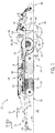
- FIG. 1 is a side view of an embodiment of an agricultural implement 10 having an orientation control system 12 (e.g., control system).
- the agricultural implement 10 is a primary tillage implement having multiple ground engaging tools configured to till soil.
- the agricultural implement 10 includes a frame 14 and a hitch assembly 16 coupled to the frame 14.
- the frame 14 is substantially rigid (e.g., does not include any translatable and/or rotatable components) and formed from multiple frame elements (e.g., rails, tubes, braces, etc.) coupled to one another (e.g., via welded connection(s), via fastener(s), etc.).
- the hitch assembly 16 includes a hitch frame 18 and a hitch 20.
- the hitch frame 18 is pivotally coupled to the implement frame 14 via pivot joint(s) 22, and the hitch 20 is configured to couple to a corresponding hitch of a work vehicle (e.g., tractor), which is configured to tow the agricultural implement 10 through a field along a direction of travel 24.
- a work vehicle e.g., tractor
- the hitch frame 18 is pivotally coupled to the implement frame 14 in the illustrated embodiment, in other embodiments, the hitch frame may be movably coupled to the implement frame by a linkage assembly (e.g., four bar linkage assembly, etc.) or another suitable assembly/mechanism that enables the hitch to move along a vertical axis 25 relative to the implement frame.
- each wheel assembly 26 includes a wheel frame and a wheel 28 rotatably coupled to the wheel frame.
- the wheels 28 of the wheel assemblies 26 are configured to engage the surface 30 of the soil 32, and the wheel assemblies 26 are configured to support at least a portion of the weight of the agricultural implement 10.
- each wheel frame is pivotally coupled to the implement frame 14, thereby facilitating adjustment of the position of each wheel 28 along the vertical axis 25.
- at least one wheel frame may be movably coupled to the implement frame by another suitable connection (e.g., sliding connection, linkage assembly, etc.) that facilitates adjustment of the vertical position of the respective wheel(s).
- the agricultural implement 10 includes ground engaging tools, such as the illustrated disc blades 34, tillage point assemblies 36, and finishing discs 38.
- the disc blades 34 are configured to engage a top layer of the soil 32. As the agricultural implement 10 is towed through the field, the disc blades 34 are driven to rotate, thereby breaking up the top layer.
- the disc blades 34 are arranged in two rows. However, in alternative embodiments, the disc blades may be arranged in more or fewer rows (e.g., 1, 2, 3, 4, 5, 6, or more).
- the angle of each row relative to the direction of travel 24 may be selected to control the interaction of the disc blades 34 with the top layer of soil 32.
- the tillage point assemblies 36 are configured to engage the soil 32 at a greater depth 40, thereby breaking up a lower layer of the soil.
- Each tillage point assembly 36 includes a tillage point 42 and a shank 44.
- the shank 44 is configured to position the tillage point 42 at the depth 40 beneath the soil surface 30, and the tillage point 42 is configured to break up the soil.
- the shape of each tillage point 42, the arrangement of the tillage point assemblies 36, and the number of tillage point assemblies 36 may be selected to control tillage within the field.
- the finishing discs 38 are driven to rotate, thereby sizing soil clods, leveling the soil surface, smoothing the soil surface, cutting residue on the soil surface, or a combination thereof.
- the finishing discs 38 are rotatably coupled to a finishing disc frame 45, and the finishing disc frame 45 is pivotally coupled to the implement frame 14.
- biasing member(s) 47 extend between the implement frame 14 and the finishing disc frame 45.
- the biasing member(s) 47 are configured to urge the finishing disc frame 45 toward the surface 30 of the soil 32, thereby driving the finishing discs 38 to engage the soil.
- the finishing disc frame is pivotally coupled to the implement frame in the illustrated embodiment, in other embodiments, the finishing disc frame may be movable coupled to the implement frame by a linkage assembly (e.g., four bar linkage assembly, etc.) or another suitable assembly/mechanism that enables the finishing disc frame to move vertically relative to the implement frame.
- the finishing disc frame may be non-translatably and/or non-rotatably coupled to the implement frame, or the finishing disc frame may be omitted, and the finishing discs may be coupled to the implement frame.
- the agricultural implement may include other and/or additional ground engaging tool(s).
- the disc blades, the tillage point assemblies, the finishing discs, or a combination thereof may be omitted in certain embodiments.
- the agricultural implement may include one or more other suitable ground engaging tools, such as coulter(s), opener(s), and tine(s), among other suitable ground engaging tools.
- the agricultural implement 10 is a primary tillage implement in the illustrated embodiment, in other embodiments, the agricultural implement may be a vertical tillage implement, another suitable type of tillage implement, a seeding implement, a planting implement, or another suitable type of implement.
- the agricultural implement 10 includes an orientation control system 12 configured to control an orientation (e.g., a fore-aft orientation and/or a side-to-side orientation) of the implement frame 14.
- the orientation control system 12 includes a first sensor 46 coupled to a first portion 48 of the implement frame 14 proximate to the disc blades 34 (e.g., first ground engaging tool).
- the first sensor 46 is directed toward the surface 30 of the soil 32, and the first sensor 46 is configured to emit a first output signal 50 toward the soil surface 30 and to receive a first return signal indicative of a first height 52 of the first portion 48 of the implement frame 14 above the soil surface 30.
- the orientation control system 12 includes a second sensor 54 coupled to a second portion 56 of the implement frame 14 proximate to the tillage point assemblies 36 (e.g., second ground engaging tool).
- the second sensor 54 is directed toward the surface 30 of the soil 32, and the second sensor 54 is configured to emit a second output signal 58 toward the soil surface 30 and to receive a second return signal indicative of a second height 60 of the second portion 56 of the implement frame 14 above the soil surface 30.
- a sensor coupled to a portion of the implement frame refers to the sensor being coupled to the implement frame (e.g., via any suitable mounting system/assembly) such that the sensor is positioned at the portion of the implement frame.
- the orientation control system 12 includes a first actuator 62 coupled to the implement frame 14 and to the hitch frame 18 of the hitch assembly 16.
- the first actuator 62 is configured to control a position of the hitch 20 of the hitch assembly 16 relative to the implement frame 14 along the vertical axis 25.
- the orientation control system 12 includes a single first actuator 62 in the illustrated embodiment, in other embodiments, the orientation control system may include more first actuators extending between the implement frame and the hitch frame.
- the first actuator 62 is coupled to the hitch frame 18 in the illustrated embodiment, in other embodiments, the first actuator may be coupled directly to the hitch or another suitable element of the hitch assembly.
- the orientation control system 12 includes a second actuator 64 coupled to the implement frame 14 and to the wheel frame of a first wheel assembly 66.
- the second actuator 64 is configured to control a position of the first wheel assembly 66 relative to the implement frame 14 along the vertical axis 25.
- the orientation control system 12 includes a single second actuator 64 in the illustrated embodiment, in other embodiments, the orientation control system may include more second actuators extending between the implement frame and the first wheel assembly.
- the agricultural implement may include a single wheel assembly, and the second actuator may be coupled to the single wheel assembly.
- the agricultural implement may include multiple wheel assemblies, and the second actuator may be coupled to the wheel assemblies (e.g., via a linkage assembly).
- the agricultural implement may include multiple wheel assemblies, and at least one second actuator may be coupled to each respective wheel assembly.
- the orientation control system 12 includes a controller communicatively coupled to the first sensor 46, to the second sensor 54, to the first actuator 62, and to the second actuator 64.
- the controller is configured to control the first and second actuators such that the difference between the first height 52 and a first target height (e.g., corresponding to a target penetration depth of corresponding ground engaging tool(s)) is less than a first threshold value (e.g., 1 mm, 2 mm, 3 mm, 5 mm, 10 mm, 15 mm, or 20 mm) and the difference between the second height 60 and a second target height (e.g., corresponding to a target penetration depth of corresponding ground engaging tool(s)) is less than a second threshold value (e.g., 1 mm, 2 mm, 3 mm, 5 mm, 10 mm, 15 mm, or 20 mm).
- a first threshold value e.g., 1 mm, 2 mm, 3 mm, 5 mm, 10 mm, 15 mm,
- the first target height may be different than the second target height. Accordingly, the controller may control the first and second actuators such that the frame tilts about a lateral axis. As a result, the penetration depth of the disc blades 34 may be adjusted substantially independently of the penetration depth of the tillage point assemblies 36 (e.g., by independently controlling the first height 52 and the second height 60). For example, as the agricultural implement traverses a field, the controller may control the first and second actuators to selectively increase or decrease the penetration depth of the disc blades while substantially maintaining the penetration depth of the tillage point assemblies.
- the controller may control the first and second actuators to selectively increase or decrease the penetration depth of the tillage point assemblies while substantially maintaining the penetration depth of the disc blades. Accordingly, control of the tillage operation may be enhanced.
- the illustrated second actuator 64 is configured to move the respective wheel 28 from the illustrated raised position to a lowered position. While the wheels 28 are in the lowered position, the ground engaging tools of the agricultural implement 10 are disengaged from the soil 32 (e.g., to facilitate transport and/or inspection of the agricultural implement 10).
- the illustrated second actuator 64 may lift the respective wheel 28 from the lowered position to the illustrated raised position (e.g., and other actuators may lift respective wheels from the lowered position to the raised position), thereby causing the ground engaging tools to engage the soil 32. Once the ground engaging tools are engaged with the soil 32, the work vehicle may tow the agricultural implement 10 throughout a field.
- the first sensor may be positioned proximate to other suitable ground engaging tool(s) (e.g., first ground engaging tool(s)).
- the first sensor may be positioned proximate to one or more coulters, tillage point assemblies, finishing discs, openers, tines, or blades, among other suitable ground engaging tool(s).
- the second sensor is positioned proximate to the tillage point assemblies in the illustrated embodiment, in other embodiments, the second sensor may be positioned proximate to other suitable ground engaging tool(s) (e.g., second ground engaging tool(s)).
- the second sensor may be positioned proximate to one or more coulters, disc blades, finishing discs, openers, tines, or blades, among other suitable ground engaging tool(s).
- a single sensor (e.g., the first sensor 46) may be positioned at (e.g., coupled to) any suitable location on the implement frame 14 (e.g., the longitudinal center of the implement frame).
- the controller may be configured to control the first and second actuators (e.g., only based on feedback from the single sensor), such that a difference between the implement frame height (e.g., height of the implement frame above the soil surface) and a target height (e.g., corresponding to a target penetration depth of the ground engaging tools) is less than a threshold value (e.g., 1 mm, 2 mm, 3 mm, 5 mm, 10 mm, 15 mm, or 20 mm).
- a threshold value e.g., 1 mm, 2 mm, 3 mm, 5 mm, 10 mm, 15 mm, or 20 mm.
- the ground engaging tools e.g., all of the ground engaging tools
- the single sensor may be the only sensor of the agricultural implement configured to provide feedback indicative of the implement frame height. Due to the reduced number of sensors, the cost of the orientation control system may be reduced, as compared to the embodiments disclosed above with multiple sensors.
- the hitch assembly may be coupled to the wheel assemblies by a mechanical linkage.
- a single actuator e.g., the first actuator
- the single actuator may control the implement frame height, thereby further reducing the cost of the orientation control system.
- the first actuator may be omitted, and the hitch frame may freely move (e.g., rotate) relative to the implement frame.
- the agricultural implement may include one or more forward wheel assemblies (e.g., one or more gauge wheel assemblies), and an actuator may extend from the implement frame to each respective forward wheel assembly.
- the controller may control each wheel actuator to control the height of the implement frame above the soil surface.
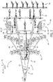
- FIG. 2 is a top view of the agricultural implement 10 of FIG. 1 .
- each wheel assembly 26 includes a wheel frame 27 and a wheel 28 rotatably coupled to the wheel frame.
- each wheel frame 27 is pivotally coupled to the implement frame 14, thereby facilitating adjustment of the position of each wheel 28 along the vertical axis.
- at least one wheel frame may be movably coupled to the implement frame by another suitable connection (e.g., sliding connection, linkage assembly, etc.) that facilitates adjustment of the vertical position of the respective wheel(s).
- the agricultural implement 10 includes two wheel assemblies 26 in the illustrated embodiment, in other embodiments, the agricultural implement may include more or fewer wheel assemblies (e.g., 1, 2, 3, 4, 5, 6, or more).
- each wheel assembly may include any suitable number of wheels (e.g., 1, 2, 3, 4, 5, 6, or more).
- the first sensor 46 is configured to emit a first output signal toward the soil surface and to receive a first return signal indicative of a first height of the first portion 48 of the implement frame 14 above the soil surface.
- the second sensor 54 is configured to emit a second output signal toward the soil surface and to receive a second return signal indicative of a second height of the second portion 56 of the implement frame 14 above the soil surface.
- the first actuator 62 is coupled to the implement frame 14 and to the hitch frame 18 of the hitch assembly 16, and the first actuator 62 is configured to control a position of the hitch 20 of the hitch assembly 16 relative to the implement frame 14 along the vertical axis.
- the second actuator 64 is coupled to the implement frame 14 and to the wheel frame 27 of the first wheel assembly 66, and the second actuator 64 is configured to control a position of the first wheel assembly 66 relative to the implement frame along the vertical axis.
- the first portion 48 is positioned forward of the second portion 56 relative to the direction of travel 24 of the agricultural implement 10.
- another second actuator may be coupled to the implement frame 14 and to a second wheel assembly 67, and the other second actuator may be configured to control a position of the second wheel assembly 67 relative to the implement frame along the vertical axis.
- the controller is configured to control the first and second actuators to tilt the implement frame 14 about a lateral axis 70 such that a difference between the first height and the first target height is less than a first threshold value, and a difference between the second height and the second target height is less than a second threshold value.
- the first target height is different than the second target height.
- the penetration depth of the disc blades 34 may be adjusted substantially independently of the penetration depth of the tillage point assemblies 36 (e.g., by independently controlling the first height and the second height).
- control of the tillage operation may be enhanced.
- the illustrated embodiment includes two wheel assemblies, in other embodiments, the agricultural implement may include more or fewer wheels assemblies (e.g., 1, 2, 3, 4, 5, 6, or more).
- the embodiment described above includes one second actuator for each wheel assembly, in other embodiments, the orientation control system may include more or fewer second actuators for each wheel assembly.
- multiple second actuators may be coupled to at least one wheel assembly, and/or a single second actuator may be coupled to multiple wheel assemblies.
- the orientation control system 12 includes a third actuator 68 coupled to the frame 14 of the agricultural implement 10 and to the second wheel assembly 67 (e.g., to the wheel frame 27 of the second wheel assembly 67).
- the third actuator 68 is communicatively coupled to the controller and configured to control a position of the second wheel assembly 67 relative to the frame 14 along the vertical axis, thereby controlling the position of the respective wheel 28 relative to the frame 14.
- the first portion is laterally offset from the second portion relative to the direction of travel 24 of the agricultural implement (e.g., the first portion is offset from the second portion along the lateral axis 70).
- the controller is configured to control the first, second, and third actuators to tilt the frame 14 about a longitudinal axis 71 (e.g., extending along the direction of travel 24) such that the difference between the first height and the first target height is less than the first threshold value, and the difference between the second height and the second target height is less than the second threshold value.
- the first target height is different than the second target height.
- the penetration depth of the ground engaging tools (e.g., disc blades 34, tillage point assemblies 36, etc.) on the left side of the agricultural implement 10 may be adjusted substantially independently of the penetration depth of the ground engaging tools (e.g., disc blades 34, tillage point assemblies 36, etc.) on the right side of the agricultural implement (e.g., by independently controlling the first height and the second height).
- control of the tillage operation may be enhanced.
- the illustrated embodiment includes two wheel assemblies, in other embodiments, the agricultural implement may include more or fewer wheels assemblies (e.g., 1, 2, 3, 4, 5, 6, or more).
- the orientation control system may include more second/third actuators for each wheel assembly.
- the hitch assembly may be coupled to the wheel assemblies by a mechanical linkage.
- the first actuator may control both the position of the hitch and the position of the wheel assemblies along the vertical axis.
- the second actuators, or the second and third actuators may extend from the mechanical linkage to the respective wheel assemblies.
- the controller is configured to control the first and second/third actuators to control the first and second heights of the implement frame.
- the first actuator may be omitted, and the hitch frame may freely move (e.g., rotate) relative to the implement frame.
- the agricultural implement may include one or more forward wheel assemblies (e.g., one or more gauge wheel assemblies), and an actuator may extend from the implement frame to each respective forward wheel assembly.
- the controller may control each wheel actuator to control the first and second heights of the implement frame.
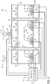
- FIG. 3 is a schematic view of an embodiment of an orientation control system 12 that may be employed within the agricultural implement of FIG. 1 .
- the orientation control system 12 includes a controller 72 communicatively coupled to the first sensor 46, to the second sensor 54, to the first actuator 62, to the second actuator 64, and to the third actuator 68.
- the controller 72 is configured to control the first, second, and third actuators such that the difference between the first height and the first target height is less than the first threshold value and the difference between the second height and the second target height is less than the second threshold value.
- the controller 72 is an element of the orientation control system 12 and may be located in/on the agricultural implement. However, in other embodiments, the controller may be located in/on a work vehicle coupled to the agricultural implement.
- one or more functions of the controller may be distributed across multiple control devices (e.g., the control devices forming the controller).
- the controller 72 is an electronic controller having electrical circuitry configured to control the first, second, and third actuators.
- the controller 72 includes a processor, such as the illustrated microprocessor 74, and a memory device 76.
- the controller 72 may also include one or more storage devices and/or other suitable components.
- the processor 74 may be used to execute software, such as software for controlling the first, second, and third actuators, and so forth.
- the processor 74 may include multiple microprocessors, one or more "general-purpose" microprocessors, one or more special-purpose microprocessors, and/or one or more application specific integrated circuits (ASICS), or some combination thereof.
- ASICS application specific integrated circuits
- the processor 74 may include one or more reduced instruction set (RISC) processors.
- RISC reduced instruction set
- the memory device 76 may include a volatile memory, such as random access memory (RAM), and/or a nonvolatile memory, such as read-only memory (ROM).
- the memory device 76 may store a variety of information and may be used for various purposes.
- the memory device 76 may store processor-executable instructions (e.g., firmware or software) for the processor 74 to execute, such as instructions for controlling the first, second, and third actuators, and so forth.
- the storage device(s) e.g., nonvolatile storage
- the storage device(s) may include ROM, flash memory, a hard drive, or any other suitable optical, magnetic, or solid-state storage medium, or a combination thereof.
- the storage device(s) may store data, instructions (e.g., software or firmware for controlling the first, second, and third actuators, etc.), and any other suitable data.
- the first sensor 46 is configured to emit a first output signal toward the soil surface and to receive a first return signal indicative of the first height of the first portion of the implement frame above the soil surface.
- the second sensor 54 is configured to emit a second output signal toward the soil surface and to receive a second return signal indicative of the second height of the second potion of the implement frame above the soil surface.
- the first sensor 46 and the second sensor 54 may include any suitable type of sensor configured to emit an output signal toward the soil surface and to receive a return signal indicative of a distance between the sensor and the soil surface.
- the first sensor and/or the second sensor may include an infrared sensor configured to emit an infrared signal toward the soil surface and to receive a return infrared signal from the soil surface.
- the first sensor and/or the second sensor may include a radio detection and ranging (RADAR) sensor (e.g., millimeter wave (MMW) scanner, etc.) configured to emit a radio frequency signal toward the soil surface and to receive a return radio frequency signal from the soil surface.
- RADAR radio detection and ranging
- MMW millimeter wave
- the first sensor and/or the second sensor may include a lidar sensor (e.g., time-of-flight scanning laser, etc.) configured to emit a light signal toward the soil surface and to receive a return light signal from the soil surface.
- the first sensor and/or the second sensor may include an ultrasonic sensor configured to emit an ultrasonic signal toward the soil surface and to receive a return ultrasonic signal from the soil surface.
- the first sensor and/or the second sensor may include a capacitive sensor configured to emit an electric signal/field toward the soil surface and to receive a return electric signal from the soil surface (e.g., in the form of a change to the emitted electric signal/field).
- first sensor and the second sensor are non-contact sensors (e.g., configured to emit an output signal and to receive a return signal) in the illustrated embodiment, in other embodiments, the first sensor and/or the second sensor may be contact sensor(s) (e.g., including a ground contact element) configured to monitor the height of the respective portion(s) of the frame above the soil surface.
- contact sensor(s) e.g., including a ground contact element
- the first actuator 62 includes a hydraulic cylinder configured to control the position of the hitch of the hitch assembly relative to the implement frame along the vertical axis.
- the orientation control system 12 includes a first valve assembly 78 configured to control a flow of fluid (e.g., hydraulic fluid) to the first actuator 62/hydraulic cylinder. Accordingly, the controller 72 is communicatively coupled to the first actuator 62 via the first valve assembly 78.
- the first valve assembly may include any suitable number and/or type(s) of valve(s) (e.g., proportional control valve(s), gate valve(s), check valve(s), needle valve(s), etc.) and other suitable component(s) (e.g., hose(s), fluid passage(s), solenoid(s), etc.) to control the flow of fluid to the first actuator 62/hydraulic cylinder (e.g., from a fluid source) and, in certain embodiments, from the first actuator 62/hydraulic cylinder (e.g., to a fluid tank, etc.).
- the valve assembly may be located on the agricultural implement, the valve assembly may be located on the work vehicle towing the agricultural implement, or the valve assembly may be distributed between the agricultural implement and the work vehicle.
- the first actuator 62 includes a single hydraulic cylinder in the illustrated embodiment, in other embodiments, the first actuator may include multiple hydraulic cylinders (e.g., 2, 3, 4, 5, 6, etc.). Furthermore, in certain embodiments, the first actuator may include any other suitable type(s) of actuator(s) (e.g., hydraulic motor(s), pneumatic cylinder(s), pneumatic motor(s), electromechanical actuator(s), linear actuator(s), screw drive(s), etc.). In embodiments in which the actuator(s) are controlled by fluid (e.g., air, hydraulic fluid, etc.), the actuator(s) may be communicatively coupled to the controller via an appropriate valve assembly.
- actuator(s) may be communicatively coupled to the controller via an appropriate valve assembly.
- the second actuator 64 includes a hydraulic cylinder configured to control the position of the respective wheel assembly relative to the implement frame along the vertical axis.
- the orientation control system 12 includes a second valve assembly 80 configured to control a flow of fluid (e.g., hydraulic fluid) to the second actuator 64/hydraulic cylinder. Accordingly, the controller 72 is communicatively coupled to the second actuator 64 via the second valve assembly 80.
- the second valve assembly may include any suitable number and/or type(s) of valve(s) (e.g., proportional control valve(s), gate valve(s), check valve(s), needle valve(s), etc.) and other suitable component(s) (e.g., hose(s), fluid passage(s), solenoid(s), etc.) to control the flow of fluid to the second actuator 64/hydraulic cylinder (e.g., from a fluid source) and, in certain embodiments, from the second actuator 64/hydraulic cylinder (e.g., to a fluid tank, etc.).
- the valve assembly may be located on the agricultural implement, the valve assembly may be located on the work vehicle towing the agricultural implement, or the valve assembly may be distributed between the agricultural implement and the work vehicle.
- the second actuator 64 includes a single hydraulic cylinder in the illustrated embodiment, in other embodiments, the second actuator may include multiple hydraulic cylinders (e.g., 2, 3, 4, 5, 6, etc.). Furthermore, in certain embodiments, the second actuator may include any other suitable type(s) of actuator(s) (e.g., hydraulic motor(s), pneumatic cylinder(s), pneumatic motor(s), electromechanical actuator(s), linear actuator(s), screw drive(s), etc.). In embodiments in which the actuator(s) are controlled by fluid (e.g., air, hydraulic fluid, etc.), the actuator(s) may be communicatively coupled to the controller via an appropriate valve assembly.
- actuator(s) may be communicatively coupled to the controller via an appropriate valve assembly.
- the third actuator 68 includes a hydraulic cylinder configured to control the position of the respective wheel assembly relative to the implement frame along the vertical axis.
- the orientation control system 12 includes a third valve assembly 82 configured to control a flow of fluid (e.g., hydraulic fluid) to the third actuator 68/hydraulic cylinder. Accordingly, the controller 72 is communicatively coupled to the third actuator 68 via the third valve assembly 82.
- the third valve assembly may include any suitable number and/or type(s) of valve(s) (e.g., proportional control valve(s), gate valve(s), check valve(s), needle valve(s), etc.) and other suitable component(s) (e.g., hose(s), fluid passage(s), solenoid(s), etc.) to control the flow of fluid to the third actuator 68/hydraulic cylinder (e.g., from a fluid source) and, in certain embodiments, from the third actuator 68/hydraulic cylinder (e.g., to a fluid tank, etc.).
- the valve assembly may be located on the agricultural implement, the valve assembly may be located on the work vehicle towing the agricultural implement, or the valve assembly may be distributed between the agricultural implement and the work vehicle.
- the third actuator 68 includes a single hydraulic cylinder in the illustrated embodiment, in other embodiments, the third actuator may include multiple hydraulic cylinders (e.g., 2, 3, 4, 5, 6, etc.). Furthermore, in certain embodiments, the third actuator may include any other suitable type(s) of actuator(s) (e.g., hydraulic motor(s), pneumatic cylinder(s), pneumatic motor(s), electromechanical actuator(s), linear actuator(s), screw drive(s), etc.). In embodiments in which the actuator(s) are controlled by fluid (e.g., air, hydraulic fluid, etc.), the actuator(s) may be communicatively coupled to the controller via an appropriate valve assembly.
- actuator(s) may be communicatively coupled to the controller via an appropriate valve assembly.
- the controller 72 is configured to control the first and second actuators such that a difference between the first height and a first target height is less than a first threshold value and a difference between the second height and a second target height is less than a second threshold value.
- the first target height may be different than the second target height.
- the controller 72 may control the first and second actuators such that the frame tilts about the lateral axis. As a result, the penetration depth of the forward ground engaging tools may be adjusted substantially independently of the penetration depth of the rearward ground engaging tools.
- the control 72 may control the first, second, and third actuators such that the difference between the first height and the first target height is less than the first threshold value and the difference between the second height and the second target height is less the second threshold value.
- the controller 74 may control the first, second, and third actuators such that the frame tilts about the longitudinal axis.
- the penetration depth of left ground engaging tools may be adjusted substantially independently of right ground engaging tools.
- the controller 72 may control the first, second, and third actuators such that the frame tilts about the lateral axis. Accordingly, control of the tillage operation may be enhanced.
- the orientation control system 12 includes a user interface 84 communicatively coupled to the controller 72.
- the user interface 84 may include any suitable control(s) configured to enable an operator to interact with (e.g., provide input to, etc.) the orientation control system 12, such as a keyboard, a mouse, one or more switches, one or more buttons, and one or more knobs.
- the operator may input the first target height, the second target height, the first threshold value, the second threshold value, other suitable parameters, or a combination thereof, into the user interface.
- the user interface may output signal(s) to the controller indicative of the input values.
- the user interface includes a display 86 configured to present information to the operator.
- the display 86 may present the first height of the first portion of the implement frame above the soil surface, the second height of the second portion of the implement frame above the soil surface, a difference between the first height and the second height, the first threshold value, the second threshold value, other suitable parameters, or a combination thereof.
- the display may include a touchscreen interface configured to enable an operator to provide input to the controller via the display.
- FIG. 4 is a top view of another embodiment of an agricultural implement 88 having wing frames rotatably coupled to a main frame 14.
- the main frame 14 e.g., implement frame
- the main frame 14 is configured to support a first group of ground engaging tools, such as the illustrated tillage point assemblies 36.
- the main frame 14 supports two rows of tillage point assemblies 36 in the illustrated embodiment, in other embodiments, the main frame 14 may support more or fewer rows of tillage point assemblies (e.g., 1, 2, 3, 4, 5, 6, 7, 8, or more).
- the main frame 14 includes tillage point assemblies 36 in the illustrated embodiment, in other embodiments, the main frame may support other suitable ground engaging tools, such as disc blades and finishing discs, among other suitable ground engaging tools.
- the agricultural implement 88 includes a first wing frame 90 pivotally coupled to the main frame 14 by one or more pivot joints 92.
- the pivot joints 92 enable the first wing frame 90 to pivot about the longitudinal axis 71 relative to the main frame 14, thereby enabling the first wing frame 90 to follow contours of the soil surface.
- the agricultural implement 88 includes a second wing frame 94 pivotally coupled to the main frame 14 by one or more pivot joints 92.
- the second wing frame 94 is positioned on the opposite lateral side of the main frame 14 from the first wing frame.
- the pivot joints 92 enable the second wing frame 94 to pivot about the longitudinal axis 71 relative to the main frame 14, thereby enabling the second wing frame 94 to follow contours of the soil surface.
- first wing frame 90 supports a second group of ground engaging tools, such as the illustrated tillage point assemblies 36
- second wing frame 94 supports a third group of ground engaging tools, such as the illustrated tillage point assemblies 36.
- Each wing frame may support the same type(s) of ground engaging tools as the main frame, or at least one wing frame may support different type(s) of ground engaging tools from the main frame.
- the agricultural implement has two wing frames in the illustrated embodiment, in other embodiments, the agricultural implement may include more or fewer wing frames.
- the agricultural implement may include a single wing frame positioned on one lateral side of the main frame.
- the agricultural implement may include multiple wing frames on at least one lateral side of the main frame (e.g., in which at least two of the wing frames are pivotally coupled to one another by respective pivot joint(s)).
- first wheel assembly 66 and the second wheel assembly 67 are movably coupled to the main frame 14.
- a third wheel assembly 96 is movably coupled to the first wing frame 90
- a fourth wheel assembly 98 is movably coupled to the second wing frame 94.
- Each wheel assembly 26 includes a wheel frame 27 and a wheel 28 rotatably coupled to the wheel frame.
- each wheel frame 27 is pivotally coupled to the respective frame (e.g., main frame or wing frame), thereby facilitating adjustment of the position of each wheel 28 along the vertical axis.
- At least one wheel frame may be movably coupled to the respective frame (e.g., main frame or wing frame) by another suitable connection (e.g., sliding connection, linkage assembly, etc.) that facilitates adjustment of the vertical position of the respective wheel(s).
- another suitable connection e.g., sliding connection, linkage assembly, etc.
- wheel assemblies 26 are coupled to the main frame 14 in the illustrated embodiment, in other embodiments, more or fewer wheel assemblies (e.g., 1, 2, 3, 4, 5, 6, or more) may be coupled to the main frame.
- one wheel assembly 26 is coupled to each wing frame in the illustrated embodiment, in other embodiments, additional wheel assemblies (e.g., 1, 2, 3, 4, 5, 6, or more) may be coupled to at least one wing frame.
- each wheel assembly may include any suitable number of wheels (e.g., 1, 2, 3, 4, 5, 6, or more).
- the hitch assembly 16 is movably coupled to the main frame 14, and the hitch 20 of the hitch assembly 16 is configured to engaging a corresponding hitch of a work vehicle (e.g., tractor), which is configured to tow the agricultural implement 88 through a field along the direction of travel 24.
- the hitch frame 18 of the hitch assembly 16 is pivotally coupled to the main frame 14 via pivot joint(s) 22.
- the hitch frame may be movably coupled to the main frame by a linkage assembly (e.g., four bar linkage assembly, etc.) or another suitable assembly/mechanism that enables the hitch to move along the vertical axis relative to the main frame.
- the orientation control system 12 includes the first sensor 46 coupled to the first portion 48 of the main frame 14 proximate to a first ground engaging tool (e.g., tillage point assembly 36) of the first group of ground engaging tools.
- the first sensor 46 is configured to emit the first output signal toward the soil surface and to receive the first return signal indicative of the first height of the first portion 48 of the main frame 14 above the soil surface.
- the orientation control system 12 includes the second sensor 54 coupled to the second portion 56 of the main frame 14 proximate to a second ground engaging tool (e.g., tillage point assembly 36) of the first group of ground engaging tools.
- the second sensor 54 is configured to emit the second output signal toward the soil surface and to receive the second return signal indicative of the second height of the second portion 56 of the main frame 14 above the soil surface.
- the orientation control system 12 includes the first actuator 62 coupled to the main frame 14 and to the hitch assembly 16.
- the first actuator 62 is configured to control the position of the hitch 20 of the hitch assembly 16 relative to the main frame 14 along the vertical axis.
- the orientation control system 12 also includes the second actuator 64 coupled to the main frame 14 and to the first wheel assembly 66.
- the second actuator 64 is configured to control the position of the first wheel assembly 66 relative to the main frame 14 along the vertical axis.
- the orientation control system 12 includes the third actuator 68 coupled to the main frame 14 and to the second wheel assembly 67.
- the third actuator 68 is configured to control the position of the second wheel assembly 67 relative to the main frame 14 along the vertical axis.
- the controller 72 is communicatively coupled to the first sensor 46, to the second sensor 54, to the first actuator 62 (e.g., via the first valve assembly), to the second actuator 64 (e.g., via the second valve assembly), and to the third actuator 68 (e.g., via the third valve assembly). Similar to the embodiment described above with reference to FIGS. 1-3 , the controller 72 is configured to control the first, second, and third actuators such that a difference between the first height and a first target height is less than a first threshold value and a difference between the second height and a second target height is less than a second threshold value. In certain embodiments, the first target height is different than the second target height.
- the penetration depth of the ground engaging tools (e.g., tillage point assemblies 36, etc.) at the first portion 48 of the main frame 14 may be adjusted substantially independently of the penetration depth of the ground engaging tools (e.g., tillage point assemblies 36, etc.) at the second portion of the main frame (e.g., by independently controlling the first height and the second height).
- control of the tillage operation may be enhanced.
- the illustrated agricultural implement/orientation control system may include any of the variations disclosed above with reference to the embodiment of FIGS. 1-3 .
- first and second portions may be located at opposite lateral sides of the main frame, the first and second portions may be located at opposite longitudinal sides of the main frame, a second actuator may be coupled to the second wheel assembly, the hitch assembly may be coupled to the wheel assemblies by a mechanical linkage, etc.
- the orientation control system 12 includes a third sensor 100 coupled to the first wing frame 90 proximate to a ground engaging tool (e.g., tillage point assembly 36) of the second group of ground engaging tools.
- the third sensor 100 is communicatively coupled to the controller 72 and directed toward the soil surface.
- the third sensor 100 is configured to emit a third output signal toward the soil surface and to receive a third return signal indicative of a third height of the first wing frame 90 above the soil surface.
- the orientation control system 12 includes a fourth sensor 102 coupled to the second wing frame 94 proximate to a ground engaging tool (e.g., tillage point assembly 36) of the third group of ground engaging tools.
- the fourth sensor 102 is communicatively coupled to the controller 72 and directed toward the soil surface.
- the fourth sensor 102 is configured to emit a fourth output signal toward the soil surface and to receive a fourth return signal indicative of a fourth height of the second wing frame 94 above the soil surface.
- the third sensor and the fourth sensor may include any suitable type of sensor, such as the sensors described above with reference to the first sensor and the second sensor.
- the orientation control system may include one sensor for each wing frame.
- the orientation control system 12 includes a fourth actuator 104 coupled to the first wing frame 90 and to the wheel frame 27 of the third wheel assembly 96.
- the fourth actuator 104 is configured to control a position of the third wheel assembly 96 relative to the first wing frame 90 along the vertical axis.
- the orientation control system 12 includes a single fourth actuator 104 in the illustrated embodiment, in other embodiments, the orientation control system may include more fourth actuators extending between the first wing frame and the third wheel assembly.
- the orientation control system may include at least one fourth actuator for each wheel assembly, or the orientation control system may include a fourth actuator coupled to multiple wheel assemblies by a linkage.
- the orientation control system 12 includes a fifth actuator 106 coupled to the second wing frame 94 and to the wheel frame 27 of the fourth wheel assembly 98.
- the fifth actuator 106 is configured to control a position of the fourth wheel assembly 98 relative to the second wing frame 94 along the vertical axis.
- the orientation control system 12 includes a single fifth actuator 106 in the illustrated embodiment, in other embodiments, the orientation control system may include more fifth actuators extending between the second wing frame and the fourth wheel assembly.
- the orientation control system may include at least one fifth actuator for each wheel assembly, or the orientation control system may include a fifth actuator coupled to multiple wheel assemblies by a linkage.
- the fourth and fifth actuators are communicatively coupled to the controller 72 (e.g., via respective valve assemblies, such as the valve assemblies described above with reference to FIG. 3 ).
- the controller is configured to control the first actuator 62, the second actuator(s) 66, and the fourth actuator 104 such that a difference between the first height and a first target height is less than a first threshold value (e.g., 1 mm, 2 mm, 3 mm, 5 mm, 10 mm, 15 mm, or 20 mm), a difference between the second height and a second target height is less than a second threshold value (e.g., 1 mm, 2 mm, 3 mm, 5 mm, 10 mm, 15 mm, or 20 mm), and a difference between the third height and a third target height (e.g., corresponding to a target penetration depth of corresponding ground engaging tool(s)) is less than a third threshold value (e.g., 1 mm, 2 mm, 3 mm, 5 mm,
- the first target height may be different than the second target height, the first target height may be different than the third target height, the second target height may be different than the third target height, or a combination thereof.
- the controller may control the first, second, and fourth actuators such that the main frame tilts about the lateral axis 70, and/or such that the height of the first wing frame is different than the height of a portion of the main frame.
- the penetration depth of forward tillage point assemblies 36 of the first group may be adjusted substantially independently of the penetration depth of rearward tillage point assemblies 36 of the first group (e.g., by independently controlling the first height and the second height), and/or the penetration depth of the second group of tillage point assemblies 36 may be adjusted substantially independently of the penetration depth of the first group of tillage point assemblies 36 (e.g., by independently controlling the third height and the first/second height). Accordingly, control of the tillage operation may be enhanced.
- the controller is configured to control the first actuator 62, the second actuator 66, the third actuator 68, and the fourth actuator 104 such that a difference between the first height and a first target height is less than a first threshold value (e.g., 1 mm, 2 mm, 3 mm, 5 mm, 10 mm, 15 mm, or 20 mm), a difference between the second height and a second target height is less than a second threshold value (e.g., 1 mm, 2 mm, 3 mm, 5 mm, 10 mm, 15 mm, or 20 mm), and a difference between the third height and a third target height is less than a third threshold value (e.g., 1 mm, 2 mm, 3 mm, 5 mm, 10 mm, 15 mm),
- a third threshold value e.g., 1 mm, 2 mm, 3 mm, 5 mm, 10 mm, 15 mm
- the first target height may be different than the second target height, the first target height may be different than the third target height, the second target height may be different than the third target height, or a combination thereof.
- the controller may control the first, second, third, and fourth actuators such that the main frame tilts about the longitudinal axis 71, and/or such that the height of the first wing frame is different than the height of a portion of the main frame.
- the penetration depth of the tillage point assemblies 36 of the first group on the left side of the main frame 14 may be adjusted substantially independently of the penetration depth of the tillage point assemblies 36 of the first group on the right side of the main frame 14 (e.g., by independently controlling the first height and the second height), and/or the penetration depth of the second group of tillage point assemblies 36 may be adjusted substantially independently of the penetration depth of the first group of tillage point assemblies 36 (e.g., by independently controlling the third height and the first/second height). Accordingly, control of the tillage operation may be enhanced.
- the controller is configured to control the first actuator 62, the second actuator 66, the third actuator 68, the fourth actuator 104, and the fifth actuator 106, such that a difference between the first height and a first target height is less than a first threshold value, a difference between the second height and a second target height is less than a second threshold value, a difference between the third height and a third target height is less than a third threshold value, and a difference between the fourth height and a fourth target height (e.g., corresponding to a target penetration depth of corresponding ground engaging tool(s)) is less than a fourth threshold value (e.g., 1 mm, 2 mm, 3 mm, 5 mm, 10 mm, 15 mm, or 20 mm).
- a fourth threshold value e.g., 1 mm, 2 mm, 3 mm, 5 mm, 10 mm, 15 mm, or 20 mm.
- the fourth target height may be different than the first target height, the second target height, the third target height, or a combination thereof.
- the controller may control the fifth actuator such that the height of the second wing frame is different than the height of a portion of the main frame and/or the height of the first wing frame.
- the penetration depth of the tillage point assemblies 36 of the third group may be adjusted substantially independently of the penetration depth of the tillage point assemblies 36 of the first group and/or the tillage point assemblies 36 of the second group. Accordingly, control of the tillage operation may be enhanced.
Landscapes
- Life Sciences & Earth Sciences (AREA)
- Soil Sciences (AREA)
- Environmental Sciences (AREA)
- Engineering & Computer Science (AREA)
- Mechanical Engineering (AREA)
- Zoology (AREA)
- Lifting Devices For Agricultural Implements (AREA)
Abstract
Description
- The present disclosure relates generally to an orientation control system for an agricultural implement.
- Certain agricultural implements include ground engaging tools configured to interact with the soil. For example, a tillage implement may include tillage points and/or disc blades configured to break up the soil for subsequent planting or seeding operations. Certain tillage implements include a depth adjustment mechanism configured to control a penetration depth of the ground engaging tools into the soil. For example, an agricultural implement may include a turnbuckle extending between a hitch assembly and a frame of the tillage implement. The turnbuckle may be adjusted to set the height of the frame relative to the surface of the soil, thereby setting the penetration depth of the ground engaging tools to a target penetration depth. However, during operation, the height of certain portion(s) of the frame above the soil surface may vary due to variations in the soil surface. As a result, the penetration depth of ground engaging tools positioned at the portion(s) of the agricultural implement frame may vary significantly from the target penetration depth. Therefore, the effectiveness of the tillage operation may be substantially reduced.
- In certain embodiments, an orientation control system for an agricultural implement includes a first sensor configured to be positioned at a first portion of a frame of the agricultural implement proximate to a first ground engaging tool. The first sensor is configured to be directed toward a soil surface, and the first sensor is configured to emit a first output signal toward the soil surface and to receive a first return signal indicative of a first height of the first portion of the frame above the soil surface. The orientation control system also includes a second sensor configured to be positioned at a second portion of the frame proximate to a second ground engaging tool. The second sensor is configured to be directed toward the soil surface, and the second sensor is configured to emit a second output signal toward the soil surface and to receive a second return signal indicative of a second height of the second portion of the frame above the soil surface. In addition, the orientation control system includes a first actuator configured to be coupled to a hitch assembly of the agricultural implement. The first actuator is configured to control a position of a hitch of the hitch assembly relative to the frame along a vertical axis. The orientation control system also includes a second actuator configured to be coupled to a wheel assembly of the agricultural implement. The second actuator is configured to control a position of the wheel assembly relative to the frame along the vertical axis. Furthermore, the orientation control system includes a controller comprising a memory and a processor. The controller is communicatively coupled to the first sensor, to the second sensor, to the first actuator, and to the second actuator, the controller is configured to control the first and second actuators such that a difference between the first height and a first target height is less than a first threshold value and a difference between the second height and a second target height is less than a second threshold value, and the first target height is different than the second target height.
- These and other features, aspects, and advantages of the present disclosure will become better understood when the following detailed description is read with reference to the accompanying drawings in which like characters represent like parts throughout the drawings, wherein:
-
FIG. 1 is a side view of an embodiment of an agricultural implement having an orientation control system; -
FIG. 2 is a top view of the agricultural implement ofFIG. 1 ; -
FIG. 3 is a schematic view of an embodiment of an orientation control system that may be employed within the agricultural implement ofFIG. 1 ; and -
FIG. 4 is a top view of another embodiment of an agricultural implement having wing frames rotatably coupled to a main frame. - One or more specific embodiments of the present disclosure will be described below. In an effort to provide a concise description of these embodiments, all features of an actual implementation may not be described in the specification. It should be appreciated that in the development of any such actual implementation, as in any engineering or design project, numerous implementation-specific decisions must be made to achieve the developers' specific goals, such as compliance with system-related and business-related constraints, which may vary from one implementation to another. Moreover, it should be appreciated that such a development effort might be complex and time consuming, but would nevertheless be a routine undertaking of design, fabrication, and manufacture for those of ordinary skill having the benefit of this disclosure.
- When introducing elements of various embodiments of the present disclosure, the articles "a," "an," "the," and "said" are intended to mean that there are one or more of the elements. The terms "comprising," "including," and "having" are intended to be inclusive and mean that there may be additional elements other than the listed elements. Any examples of operating parameters and/or environmental conditions are not exclusive of other parameters/conditions of the disclosed embodiments.
-
FIG. 1 is a side view of an embodiment of anagricultural implement 10 having an orientation control system 12 (e.g., control system). In the illustrated embodiment, theagricultural implement 10 is a primary tillage implement having multiple ground engaging tools configured to till soil. As illustrated, theagricultural implement 10 includes aframe 14 and ahitch assembly 16 coupled to theframe 14. Theframe 14 is substantially rigid (e.g., does not include any translatable and/or rotatable components) and formed from multiple frame elements (e.g., rails, tubes, braces, etc.) coupled to one another (e.g., via welded connection(s), via fastener(s), etc.). Thehitch assembly 16 includes ahitch frame 18 and ahitch 20. Thehitch frame 18 is pivotally coupled to theimplement frame 14 via pivot joint(s) 22, and thehitch 20 is configured to couple to a corresponding hitch of a work vehicle (e.g., tractor), which is configured to tow theagricultural implement 10 through a field along a direction oftravel 24. While thehitch frame 18 is pivotally coupled to theimplement frame 14 in the illustrated embodiment, in other embodiments, the hitch frame may be movably coupled to the implement frame by a linkage assembly (e.g., four bar linkage assembly, etc.) or another suitable assembly/mechanism that enables the hitch to move along a vertical axis 25 relative to the implement frame. - As illustrated, the
agricultural implement 10 includes wheel assemblies 26 movably coupled to theimplement frame 14. In the illustrated embodiment, each wheel assembly 26 includes a wheel frame and awheel 28 rotatably coupled to the wheel frame. Thewheels 28 of the wheel assemblies 26 are configured to engage thesurface 30 of thesoil 32, and the wheel assemblies 26 are configured to support at least a portion of the weight of theagricultural implement 10. In the illustrated embodiment, each wheel frame is pivotally coupled to theimplement frame 14, thereby facilitating adjustment of the position of eachwheel 28 along the vertical axis 25. However, in other embodiments, at least one wheel frame may be movably coupled to the implement frame by another suitable connection (e.g., sliding connection, linkage assembly, etc.) that facilitates adjustment of the vertical position of the respective wheel(s). - In the illustrated embodiment, the
agricultural implement 10 includes ground engaging tools, such as the illustrateddisc blades 34,tillage point assemblies 36, andfinishing discs 38. Thedisc blades 34 are configured to engage a top layer of thesoil 32. As theagricultural implement 10 is towed through the field, thedisc blades 34 are driven to rotate, thereby breaking up the top layer. In the illustrated embodiment, thedisc blades 34 are arranged in two rows. However, in alternative embodiments, the disc blades may be arranged in more or fewer rows (e.g., 1, 2, 3, 4, 5, 6, or more). In addition, the angle of each row relative to the direction oftravel 24 may be selected to control the interaction of thedisc blades 34 with the top layer ofsoil 32. Thetillage point assemblies 36 are configured to engage thesoil 32 at agreater depth 40, thereby breaking up a lower layer of the soil. Eachtillage point assembly 36 includes atillage point 42 and ashank 44. Theshank 44 is configured to position thetillage point 42 at thedepth 40 beneath thesoil surface 30, and thetillage point 42 is configured to break up the soil. The shape of eachtillage point 42, the arrangement of the tillage point assemblies 36, and the number oftillage point assemblies 36 may be selected to control tillage within the field. Furthermore, as theagricultural implement 10 is towed through the field, thefinishing discs 38 are driven to rotate, thereby sizing soil clods, leveling the soil surface, smoothing the soil surface, cutting residue on the soil surface, or a combination thereof. - In the illustrated embodiment, the
finishing discs 38 are rotatably coupled to afinishing disc frame 45, and thefinishing disc frame 45 is pivotally coupled to theimplement frame 14. In addition, biasing member(s) 47 extend between theimplement frame 14 and thefinishing disc frame 45. The biasing member(s) 47 are configured to urge thefinishing disc frame 45 toward thesurface 30 of thesoil 32, thereby driving thefinishing discs 38 to engage the soil. While the finishing disc frame is pivotally coupled to the implement frame in the illustrated embodiment, in other embodiments, the finishing disc frame may be movable coupled to the implement frame by a linkage assembly (e.g., four bar linkage assembly, etc.) or another suitable assembly/mechanism that enables the finishing disc frame to move vertically relative to the implement frame. Furthermore, in certain embodiments, the finishing disc frame may be non-translatably and/or non-rotatably coupled to the implement frame, or the finishing disc frame may be omitted, and the finishing discs may be coupled to the implement frame. - While the illustrated agricultural implement includes the
disc blades 34, the tillage point assemblies 36, and thefinishing discs 38, in other embodiments, the agricultural implement may include other and/or additional ground engaging tool(s). For example, the disc blades, the tillage point assemblies, the finishing discs, or a combination thereof, may be omitted in certain embodiments. Furthermore, in certain embodiments, the agricultural implement may include one or more other suitable ground engaging tools, such as coulter(s), opener(s), and tine(s), among other suitable ground engaging tools. Furthermore, while the agricultural implement 10 is a primary tillage implement in the illustrated embodiment, in other embodiments, the agricultural implement may be a vertical tillage implement, another suitable type of tillage implement, a seeding implement, a planting implement, or another suitable type of implement. - In the illustrated embodiment, the agricultural implement 10 includes an
orientation control system 12 configured to control an orientation (e.g., a fore-aft orientation and/or a side-to-side orientation) of the implementframe 14. Theorientation control system 12 includes afirst sensor 46 coupled to afirst portion 48 of the implementframe 14 proximate to the disc blades 34 (e.g., first ground engaging tool). Thefirst sensor 46 is directed toward thesurface 30 of thesoil 32, and thefirst sensor 46 is configured to emit afirst output signal 50 toward thesoil surface 30 and to receive a first return signal indicative of afirst height 52 of thefirst portion 48 of the implementframe 14 above thesoil surface 30. In addition, theorientation control system 12 includes asecond sensor 54 coupled to asecond portion 56 of the implementframe 14 proximate to the tillage point assemblies 36 (e.g., second ground engaging tool). Thesecond sensor 54 is directed toward thesurface 30 of thesoil 32, and thesecond sensor 54 is configured to emit asecond output signal 58 toward thesoil surface 30 and to receive a second return signal indicative of asecond height 60 of thesecond portion 56 of the implementframe 14 above thesoil surface 30. As used herein, a sensor coupled to a portion of the implement frame refers to the sensor being coupled to the implement frame (e.g., via any suitable mounting system/assembly) such that the sensor is positioned at the portion of the implement frame. - Furthermore, the
orientation control system 12 includes afirst actuator 62 coupled to the implementframe 14 and to thehitch frame 18 of thehitch assembly 16. Thefirst actuator 62 is configured to control a position of thehitch 20 of thehitch assembly 16 relative to the implementframe 14 along the vertical axis 25. While theorientation control system 12 includes a singlefirst actuator 62 in the illustrated embodiment, in other embodiments, the orientation control system may include more first actuators extending between the implement frame and the hitch frame. Furthermore, while thefirst actuator 62 is coupled to thehitch frame 18 in the illustrated embodiment, in other embodiments, the first actuator may be coupled directly to the hitch or another suitable element of the hitch assembly. In addition, theorientation control system 12 includes asecond actuator 64 coupled to the implementframe 14 and to the wheel frame of a first wheel assembly 66. Thesecond actuator 64 is configured to control a position of the first wheel assembly 66 relative to the implementframe 14 along the vertical axis 25. While theorientation control system 12 includes a singlesecond actuator 64 in the illustrated embodiment, in other embodiments, the orientation control system may include more second actuators extending between the implement frame and the first wheel assembly. Furthermore, in certain embodiments, the agricultural implement may include a single wheel assembly, and the second actuator may be coupled to the single wheel assembly. In other embodiments, the agricultural implement may include multiple wheel assemblies, and the second actuator may be coupled to the wheel assemblies (e.g., via a linkage assembly). Furthermore, in certain embodiments, the agricultural implement may include multiple wheel assemblies, and at least one second actuator may be coupled to each respective wheel assembly. - As discussed in detail below, the
orientation control system 12 includes a controller communicatively coupled to thefirst sensor 46, to thesecond sensor 54, to thefirst actuator 62, and to thesecond actuator 64. The controller is configured to control the first and second actuators such that the difference between thefirst height 52 and a first target height (e.g., corresponding to a target penetration depth of corresponding ground engaging tool(s)) is less than a first threshold value (e.g., 1 mm, 2 mm, 3 mm, 5 mm, 10 mm, 15 mm, or 20 mm) and the difference between thesecond height 60 and a second target height (e.g., corresponding to a target penetration depth of corresponding ground engaging tool(s)) is less than a second threshold value (e.g., 1 mm, 2 mm, 3 mm, 5 mm, 10 mm, 15 mm, or 20 mm). The first target height may be different than the second target height. Accordingly, the controller may control the first and second actuators such that the frame tilts about a lateral axis. As a result, the penetration depth of thedisc blades 34 may be adjusted substantially independently of the penetration depth of the tillage point assemblies 36 (e.g., by independently controlling thefirst height 52 and the second height 60). For example, as the agricultural implement traverses a field, the controller may control the first and second actuators to selectively increase or decrease the penetration depth of the disc blades while substantially maintaining the penetration depth of the tillage point assemblies. In addition, as the agricultural implement traverses the field, the controller may control the first and second actuators to selectively increase or decrease the penetration depth of the tillage point assemblies while substantially maintaining the penetration depth of the disc blades. Accordingly, control of the tillage operation may be enhanced. - In certain embodiments, the illustrated
second actuator 64 is configured to move therespective wheel 28 from the illustrated raised position to a lowered position. While thewheels 28 are in the lowered position, the ground engaging tools of the agricultural implement 10 are disengaged from the soil 32 (e.g., to facilitate transport and/or inspection of the agricultural implement 10). The illustratedsecond actuator 64 may lift therespective wheel 28 from the lowered position to the illustrated raised position (e.g., and other actuators may lift respective wheels from the lowered position to the raised position), thereby causing the ground engaging tools to engage thesoil 32. Once the ground engaging tools are engaged with thesoil 32, the work vehicle may tow the agricultural implement 10 throughout a field. - While the first sensor is positioned proximate to the disc blades in the illustrated embodiment, in other embodiments, the first sensor may be positioned proximate to other suitable ground engaging tool(s) (e.g., first ground engaging tool(s)). For example, the first sensor may be positioned proximate to one or more coulters, tillage point assemblies, finishing discs, openers, tines, or blades, among other suitable ground engaging tool(s). In addition, while the second sensor is positioned proximate to the tillage point assemblies in the illustrated embodiment, in other embodiments, the second sensor may be positioned proximate to other suitable ground engaging tool(s) (e.g., second ground engaging tool(s)). For example, the second sensor may be positioned proximate to one or more coulters, disc blades, finishing discs, openers, tines, or blades, among other suitable ground engaging tool(s).
- In certain embodiments, a single sensor (e.g., the first sensor 46) may be positioned at (e.g., coupled to) any suitable location on the implement frame 14 (e.g., the longitudinal center of the implement frame). In such embodiments, the controller may be configured to control the first and second actuators (e.g., only based on feedback from the single sensor), such that a difference between the implement frame height (e.g., height of the implement frame above the soil surface) and a target height (e.g., corresponding to a target penetration depth of the ground engaging tools) is less than a threshold value (e.g., 1 mm, 2 mm, 3 mm, 5 mm, 10 mm, 15 mm, or 20 mm). Accordingly, at least a portion of the ground engaging tools (e.g., all of the ground engaging tools) on the implement frame may be substantially maintained at a target penetration depth beneath the soil surface, thereby enhancing the effectiveness of the agricultural operation. The single sensor may be the only sensor of the agricultural implement configured to provide feedback indicative of the implement frame height. Due to the reduced number of sensors, the cost of the orientation control system may be reduced, as compared to the embodiments disclosed above with multiple sensors. In certain embodiments, the hitch assembly may be coupled to the wheel assemblies by a mechanical linkage. In such embodiments, a single actuator (e.g., the first actuator) may control both the position of the hitch and the position of the wheel assemblies along the vertical axis. Accordingly, the single actuator (e.g., first actuator) may control the implement frame height, thereby further reducing the cost of the orientation control system. Furthermore, in certain embodiments, the first actuator may be omitted, and the hitch frame may freely move (e.g., rotate) relative to the implement frame. In such embodiments, the agricultural implement may include one or more forward wheel assemblies (e.g., one or more gauge wheel assemblies), and an actuator may extend from the implement frame to each respective forward wheel assembly. The controller may control each wheel actuator to control the height of the implement frame above the soil surface.
-
FIG. 2 is a top view of the agricultural implement 10 ofFIG. 1 . As previously discussed, each wheel assembly 26 includes awheel frame 27 and awheel 28 rotatably coupled to the wheel frame. In the illustrated embodiment, eachwheel frame 27 is pivotally coupled to the implementframe 14, thereby facilitating adjustment of the position of eachwheel 28 along the vertical axis. However, in other embodiments, at least one wheel frame may be movably coupled to the implement frame by another suitable connection (e.g., sliding connection, linkage assembly, etc.) that facilitates adjustment of the vertical position of the respective wheel(s). Furthermore, while the agricultural implement 10 includes two wheel assemblies 26 in the illustrated embodiment, in other embodiments, the agricultural implement may include more or fewer wheel assemblies (e.g., 1, 2, 3, 4, 5, 6, or more). In addition, each wheel assembly may include any suitable number of wheels (e.g., 1, 2, 3, 4, 5, 6, or more). - As previously discussed, the
first sensor 46 is configured to emit a first output signal toward the soil surface and to receive a first return signal indicative of a first height of thefirst portion 48 of the implementframe 14 above the soil surface. In addition, thesecond sensor 54 is configured to emit a second output signal toward the soil surface and to receive a second return signal indicative of a second height of thesecond portion 56 of the implementframe 14 above the soil surface. Furthermore, as illustrated, thefirst actuator 62 is coupled to the implementframe 14 and to thehitch frame 18 of thehitch assembly 16, and thefirst actuator 62 is configured to control a position of thehitch 20 of thehitch assembly 16 relative to the implementframe 14 along the vertical axis. In addition, thesecond actuator 64 is coupled to the implementframe 14 and to thewheel frame 27 of the first wheel assembly 66, and thesecond actuator 64 is configured to control a position of the first wheel assembly 66 relative to the implement frame along the vertical axis. - In certain embodiments, the
first portion 48 is positioned forward of thesecond portion 56 relative to the direction oftravel 24 of the agricultural implement 10. In such embodiments, another second actuator may be coupled to the implementframe 14 and to a second wheel assembly 67, and the other second actuator may be configured to control a position of the second wheel assembly 67 relative to the implement frame along the vertical axis. In addition, the controller is configured to control the first and second actuators to tilt the implementframe 14 about alateral axis 70 such that a difference between the first height and the first target height is less than a first threshold value, and a difference between the second height and the second target height is less than a second threshold value. In certain embodiments, the first target height is different than the second target height. Accordingly, the penetration depth of thedisc blades 34 may be adjusted substantially independently of the penetration depth of the tillage point assemblies 36 (e.g., by independently controlling the first height and the second height). As a result, control of the tillage operation may be enhanced. While the illustrated embodiment includes two wheel assemblies, in other embodiments, the agricultural implement may include more or fewer wheels assemblies (e.g., 1, 2, 3, 4, 5, 6, or more). In addition, while the embodiment described above includes one second actuator for each wheel assembly, in other embodiments, the orientation control system may include more or fewer second actuators for each wheel assembly. For example, in certain embodiments, multiple second actuators may be coupled to at least one wheel assembly, and/or a single second actuator may be coupled to multiple wheel assemblies. - In the illustrated embodiment, the
orientation control system 12 includes athird actuator 68 coupled to theframe 14 of the agricultural implement 10 and to the second wheel assembly 67 (e.g., to thewheel frame 27 of the second wheel assembly 67). Thethird actuator 68 is communicatively coupled to the controller and configured to control a position of the second wheel assembly 67 relative to theframe 14 along the vertical axis, thereby controlling the position of therespective wheel 28 relative to theframe 14. In certain embodiments, the first portion is laterally offset from the second portion relative to the direction oftravel 24 of the agricultural implement (e.g., the first portion is offset from the second portion along the lateral axis 70). In such embodiments, the controller is configured to control the first, second, and third actuators to tilt theframe 14 about a longitudinal axis 71 (e.g., extending along the direction of travel 24) such that the difference between the first height and the first target height is less than the first threshold value, and the difference between the second height and the second target height is less than the second threshold value. In certain embodiments, the first target height is different than the second target height. Accordingly, the penetration depth of the ground engaging tools (e.g.,disc blades 34,tillage point assemblies 36, etc.) on the left side of the agricultural implement 10 may be adjusted substantially independently of the penetration depth of the ground engaging tools (e.g.,disc blades 34,tillage point assemblies 36, etc.) on the right side of the agricultural implement (e.g., by independently controlling the first height and the second height). As a result, control of the tillage operation may be enhanced. While the illustrated embodiment includes two wheel assemblies, in other embodiments, the agricultural implement may include more or fewer wheels assemblies (e.g., 1, 2, 3, 4, 5, 6, or more). In addition, while the embodiment described above includes one second/third actuator for each wheel assembly, in other embodiments, the orientation control system may include more second/third actuators for each wheel assembly. - In certain embodiments, the hitch assembly may be coupled to the wheel assemblies by a mechanical linkage. In such embodiments, the first actuator may control both the position of the hitch and the position of the wheel assemblies along the vertical axis. In addition, the second actuators, or the second and third actuators, may extend from the mechanical linkage to the respective wheel assemblies. Accordingly, the controller is configured to control the first and second/third actuators to control the first and second heights of the implement frame. Furthermore, in certain embodiments, the first actuator may be omitted, and the hitch frame may freely move (e.g., rotate) relative to the implement frame. In such embodiments, the agricultural implement may include one or more forward wheel assemblies (e.g., one or more gauge wheel assemblies), and an actuator may extend from the implement frame to each respective forward wheel assembly. The controller may control each wheel actuator to control the first and second heights of the implement frame.
-
FIG. 3 is a schematic view of an embodiment of anorientation control system 12 that may be employed within the agricultural implement ofFIG. 1 . In the illustrated embodiment, theorientation control system 12 includes acontroller 72 communicatively coupled to thefirst sensor 46, to thesecond sensor 54, to thefirst actuator 62, to thesecond actuator 64, and to thethird actuator 68. Thecontroller 72 is configured to control the first, second, and third actuators such that the difference between the first height and the first target height is less than the first threshold value and the difference between the second height and the second target height is less than the second threshold value. In the illustrated embodiment, thecontroller 72 is an element of theorientation control system 12 and may be located in/on the agricultural implement. However, in other embodiments, the controller may be located in/on a work vehicle coupled to the agricultural implement. Furthermore, in certain embodiments, one or more functions of the controller may be distributed across multiple control devices (e.g., the control devices forming the controller). - In certain embodiments, the
controller 72 is an electronic controller having electrical circuitry configured to control the first, second, and third actuators. In the illustrated embodiment, thecontroller 72 includes a processor, such as the illustratedmicroprocessor 74, and amemory device 76. Thecontroller 72 may also include one or more storage devices and/or other suitable components. Theprocessor 74 may be used to execute software, such as software for controlling the first, second, and third actuators, and so forth. Moreover, theprocessor 74 may include multiple microprocessors, one or more "general-purpose" microprocessors, one or more special-purpose microprocessors, and/or one or more application specific integrated circuits (ASICS), or some combination thereof. For example, theprocessor 74 may include one or more reduced instruction set (RISC) processors. - The
memory device 76 may include a volatile memory, such as random access memory (RAM), and/or a nonvolatile memory, such as read-only memory (ROM). Thememory device 76 may store a variety of information and may be used for various purposes. For example, thememory device 76 may store processor-executable instructions (e.g., firmware or software) for theprocessor 74 to execute, such as instructions for controlling the first, second, and third actuators, and so forth. The storage device(s) (e.g., nonvolatile storage) may include ROM, flash memory, a hard drive, or any other suitable optical, magnetic, or solid-state storage medium, or a combination thereof. The storage device(s) may store data, instructions (e.g., software or firmware for controlling the first, second, and third actuators, etc.), and any other suitable data. - As previously discussed, the
first sensor 46 is configured to emit a first output signal toward the soil surface and to receive a first return signal indicative of the first height of the first portion of the implement frame above the soil surface. In addition, thesecond sensor 54 is configured to emit a second output signal toward the soil surface and to receive a second return signal indicative of the second height of the second potion of the implement frame above the soil surface. Thefirst sensor 46 and thesecond sensor 54 may include any suitable type of sensor configured to emit an output signal toward the soil surface and to receive a return signal indicative of a distance between the sensor and the soil surface. In certain embodiments, the first sensor and/or the second sensor may include an infrared sensor configured to emit an infrared signal toward the soil surface and to receive a return infrared signal from the soil surface. Furthermore, in certain embodiments, the first sensor and/or the second sensor may include a radio detection and ranging (RADAR) sensor (e.g., millimeter wave (MMW) scanner, etc.) configured to emit a radio frequency signal toward the soil surface and to receive a return radio frequency signal from the soil surface. In addition, in certain embodiments, the first sensor and/or the second sensor may include a lidar sensor (e.g., time-of-flight scanning laser, etc.) configured to emit a light signal toward the soil surface and to receive a return light signal from the soil surface. By way of further example, in certain embodiments, the first sensor and/or the second sensor may include an ultrasonic sensor configured to emit an ultrasonic signal toward the soil surface and to receive a return ultrasonic signal from the soil surface. Furthermore, in certain embodiments, the first sensor and/or the second sensor may include a capacitive sensor configured to emit an electric signal/field toward the soil surface and to receive a return electric signal from the soil surface (e.g., in the form of a change to the emitted electric signal/field). While the first sensor and the second sensor are non-contact sensors (e.g., configured to emit an output signal and to receive a return signal) in the illustrated embodiment, in other embodiments, the first sensor and/or the second sensor may be contact sensor(s) (e.g., including a ground contact element) configured to monitor the height of the respective portion(s) of the frame above the soil surface. - In the illustrated embodiment, the
first actuator 62 includes a hydraulic cylinder configured to control the position of the hitch of the hitch assembly relative to the implement frame along the vertical axis. In addition, theorientation control system 12 includes afirst valve assembly 78 configured to control a flow of fluid (e.g., hydraulic fluid) to thefirst actuator 62/hydraulic cylinder. Accordingly, thecontroller 72 is communicatively coupled to thefirst actuator 62 via thefirst valve assembly 78. The first valve assembly may include any suitable number and/or type(s) of valve(s) (e.g., proportional control valve(s), gate valve(s), check valve(s), needle valve(s), etc.) and other suitable component(s) (e.g., hose(s), fluid passage(s), solenoid(s), etc.) to control the flow of fluid to thefirst actuator 62/hydraulic cylinder (e.g., from a fluid source) and, in certain embodiments, from thefirst actuator 62/hydraulic cylinder (e.g., to a fluid tank, etc.). The valve assembly may be located on the agricultural implement, the valve assembly may be located on the work vehicle towing the agricultural implement, or the valve assembly may be distributed between the agricultural implement and the work vehicle. While thefirst actuator 62 includes a single hydraulic cylinder in the illustrated embodiment, in other embodiments, the first actuator may include multiple hydraulic cylinders (e.g., 2, 3, 4, 5, 6, etc.). Furthermore, in certain embodiments, the first actuator may include any other suitable type(s) of actuator(s) (e.g., hydraulic motor(s), pneumatic cylinder(s), pneumatic motor(s), electromechanical actuator(s), linear actuator(s), screw drive(s), etc.). In embodiments in which the actuator(s) are controlled by fluid (e.g., air, hydraulic fluid, etc.), the actuator(s) may be communicatively coupled to the controller via an appropriate valve assembly. - In the illustrated embodiment, the
second actuator 64 includes a hydraulic cylinder configured to control the position of the respective wheel assembly relative to the implement frame along the vertical axis. In addition, theorientation control system 12 includes asecond valve assembly 80 configured to control a flow of fluid (e.g., hydraulic fluid) to thesecond actuator 64/hydraulic cylinder. Accordingly, thecontroller 72 is communicatively coupled to thesecond actuator 64 via thesecond valve assembly 80. The second valve assembly may include any suitable number and/or type(s) of valve(s) (e.g., proportional control valve(s), gate valve(s), check valve(s), needle valve(s), etc.) and other suitable component(s) (e.g., hose(s), fluid passage(s), solenoid(s), etc.) to control the flow of fluid to thesecond actuator 64/hydraulic cylinder (e.g., from a fluid source) and, in certain embodiments, from thesecond actuator 64/hydraulic cylinder (e.g., to a fluid tank, etc.). The valve assembly may be located on the agricultural implement, the valve assembly may be located on the work vehicle towing the agricultural implement, or the valve assembly may be distributed between the agricultural implement and the work vehicle. While thesecond actuator 64 includes a single hydraulic cylinder in the illustrated embodiment, in other embodiments, the second actuator may include multiple hydraulic cylinders (e.g., 2, 3, 4, 5, 6, etc.). Furthermore, in certain embodiments, the second actuator may include any other suitable type(s) of actuator(s) (e.g., hydraulic motor(s), pneumatic cylinder(s), pneumatic motor(s), electromechanical actuator(s), linear actuator(s), screw drive(s), etc.). In embodiments in which the actuator(s) are controlled by fluid (e.g., air, hydraulic fluid, etc.), the actuator(s) may be communicatively coupled to the controller via an appropriate valve assembly. - In the illustrated embodiment, the
third actuator 68 includes a hydraulic cylinder configured to control the position of the respective wheel assembly relative to the implement frame along the vertical axis. In addition, theorientation control system 12 includes athird valve assembly 82 configured to control a flow of fluid (e.g., hydraulic fluid) to thethird actuator 68/hydraulic cylinder. Accordingly, thecontroller 72 is communicatively coupled to thethird actuator 68 via thethird valve assembly 82. The third valve assembly may include any suitable number and/or type(s) of valve(s) (e.g., proportional control valve(s), gate valve(s), check valve(s), needle valve(s), etc.) and other suitable component(s) (e.g., hose(s), fluid passage(s), solenoid(s), etc.) to control the flow of fluid to thethird actuator 68/hydraulic cylinder (e.g., from a fluid source) and, in certain embodiments, from thethird actuator 68/hydraulic cylinder (e.g., to a fluid tank, etc.). The valve assembly may be located on the agricultural implement, the valve assembly may be located on the work vehicle towing the agricultural implement, or the valve assembly may be distributed between the agricultural implement and the work vehicle. While thethird actuator 68 includes a single hydraulic cylinder in the illustrated embodiment, in other embodiments, the third actuator may include multiple hydraulic cylinders (e.g., 2, 3, 4, 5, 6, etc.). Furthermore, in certain embodiments, the third actuator may include any other suitable type(s) of actuator(s) (e.g., hydraulic motor(s), pneumatic cylinder(s), pneumatic motor(s), electromechanical actuator(s), linear actuator(s), screw drive(s), etc.). In embodiments in which the actuator(s) are controlled by fluid (e.g., air, hydraulic fluid, etc.), the actuator(s) may be communicatively coupled to the controller via an appropriate valve assembly. - In certain embodiments (e.g., embodiments in which a second actuator is coupled to each wheel assembly of the implement frame), the
controller 72 is configured to control the first and second actuators such that a difference between the first height and a first target height is less than a first threshold value and a difference between the second height and a second target height is less than a second threshold value. The first target height may be different than the second target height. Accordingly, thecontroller 72 may control the first and second actuators such that the frame tilts about the lateral axis. As a result, the penetration depth of the forward ground engaging tools may be adjusted substantially independently of the penetration depth of the rearward ground engaging tools. In addition, in certain embodiments (e.g., embodiments in which the second actuator is coupled to the first wheel assembly, and the third actuator is coupled to the second wheel assembly), thecontrol 72 may control the first, second, and third actuators such that the difference between the first height and the first target height is less than the first threshold value and the difference between the second height and the second target height is less the second threshold value. Accordingly, thecontroller 74 may control the first, second, and third actuators such that the frame tilts about the longitudinal axis. As a result, the penetration depth of left ground engaging tools may be adjusted substantially independently of right ground engaging tools. Additionally or alternatively, thecontroller 72 may control the first, second, and third actuators such that the frame tilts about the lateral axis. Accordingly, control of the tillage operation may be enhanced. - In the illustrated embodiment, the
orientation control system 12 includes auser interface 84 communicatively coupled to thecontroller 72. Theuser interface 84 may include any suitable control(s) configured to enable an operator to interact with (e.g., provide input to, etc.) theorientation control system 12, such as a keyboard, a mouse, one or more switches, one or more buttons, and one or more knobs. For example, the operator may input the first target height, the second target height, the first threshold value, the second threshold value, other suitable parameters, or a combination thereof, into the user interface. The user interface, in turn, may output signal(s) to the controller indicative of the input values. In the illustrated embodiment, the user interface includes adisplay 86 configured to present information to the operator. For example, thedisplay 86 may present the first height of the first portion of the implement frame above the soil surface, the second height of the second portion of the implement frame above the soil surface, a difference between the first height and the second height, the first threshold value, the second threshold value, other suitable parameters, or a combination thereof. In addition, in certain embodiments, the display may include a touchscreen interface configured to enable an operator to provide input to the controller via the display. -
FIG. 4 is a top view of another embodiment of an agricultural implement 88 having wing frames rotatably coupled to amain frame 14. In the illustrated embodiment, the main frame 14 (e.g., implement frame) is configured to support a first group of ground engaging tools, such as the illustratedtillage point assemblies 36. While themain frame 14 supports two rows oftillage point assemblies 36 in the illustrated embodiment, in other embodiments, themain frame 14 may support more or fewer rows of tillage point assemblies (e.g., 1, 2, 3, 4, 5, 6, 7, 8, or more). Furthermore, while themain frame 14 includestillage point assemblies 36 in the illustrated embodiment, in other embodiments, the main frame may support other suitable ground engaging tools, such as disc blades and finishing discs, among other suitable ground engaging tools. - In the illustrated embodiment, the agricultural implement 88 includes a
first wing frame 90 pivotally coupled to themain frame 14 by one or more pivot joints 92. The pivot joints 92 enable thefirst wing frame 90 to pivot about the longitudinal axis 71 relative to themain frame 14, thereby enabling thefirst wing frame 90 to follow contours of the soil surface. Furthermore, the agricultural implement 88 includes asecond wing frame 94 pivotally coupled to themain frame 14 by one or more pivot joints 92. Thesecond wing frame 94 is positioned on the opposite lateral side of themain frame 14 from the first wing frame. The pivot joints 92 enable thesecond wing frame 94 to pivot about the longitudinal axis 71 relative to themain frame 14, thereby enabling thesecond wing frame 94 to follow contours of the soil surface. Furthermore, thefirst wing frame 90 supports a second group of ground engaging tools, such as the illustratedtillage point assemblies 36, and thesecond wing frame 94 supports a third group of ground engaging tools, such as the illustratedtillage point assemblies 36. Each wing frame may support the same type(s) of ground engaging tools as the main frame, or at least one wing frame may support different type(s) of ground engaging tools from the main frame. While the agricultural implement has two wing frames in the illustrated embodiment, in other embodiments, the agricultural implement may include more or fewer wing frames. For example, the agricultural implement may include a single wing frame positioned on one lateral side of the main frame. In addition, the agricultural implement may include multiple wing frames on at least one lateral side of the main frame (e.g., in which at least two of the wing frames are pivotally coupled to one another by respective pivot joint(s)). - In the illustrated embodiment, the first wheel assembly 66 and the second wheel assembly 67 are movably coupled to the
main frame 14. In addition, a third wheel assembly 96 is movably coupled to thefirst wing frame 90, and a fourth wheel assembly 98 is movably coupled to thesecond wing frame 94. Each wheel assembly 26 includes awheel frame 27 and awheel 28 rotatably coupled to the wheel frame. In the illustrated embodiment, eachwheel frame 27 is pivotally coupled to the respective frame (e.g., main frame or wing frame), thereby facilitating adjustment of the position of eachwheel 28 along the vertical axis. However, in other embodiments, at least one wheel frame may be movably coupled to the respective frame (e.g., main frame or wing frame) by another suitable connection (e.g., sliding connection, linkage assembly, etc.) that facilitates adjustment of the vertical position of the respective wheel(s). Furthermore, while two wheel assemblies 26 are coupled to themain frame 14 in the illustrated embodiment, in other embodiments, more or fewer wheel assemblies (e.g., 1, 2, 3, 4, 5, 6, or more) may be coupled to the main frame. While one wheel assembly 26 is coupled to each wing frame in the illustrated embodiment, in other embodiments, additional wheel assemblies (e.g., 1, 2, 3, 4, 5, 6, or more) may be coupled to at least one wing frame. In addition, each wheel assembly may include any suitable number of wheels (e.g., 1, 2, 3, 4, 5, 6, or more). - As illustrated, the
hitch assembly 16 is movably coupled to themain frame 14, and thehitch 20 of thehitch assembly 16 is configured to engaging a corresponding hitch of a work vehicle (e.g., tractor), which is configured to tow the agricultural implement 88 through a field along the direction oftravel 24. Thehitch frame 18 of thehitch assembly 16 is pivotally coupled to themain frame 14 via pivot joint(s) 22. However, in other embodiments, the hitch frame may be movably coupled to the main frame by a linkage assembly (e.g., four bar linkage assembly, etc.) or another suitable assembly/mechanism that enables the hitch to move along the vertical axis relative to the main frame. - In the illustrated embodiment, the
orientation control system 12 includes thefirst sensor 46 coupled to thefirst portion 48 of themain frame 14 proximate to a first ground engaging tool (e.g., tillage point assembly 36) of the first group of ground engaging tools. As previously discussed, thefirst sensor 46 is configured to emit the first output signal toward the soil surface and to receive the first return signal indicative of the first height of thefirst portion 48 of themain frame 14 above the soil surface. In addition, theorientation control system 12 includes thesecond sensor 54 coupled to thesecond portion 56 of themain frame 14 proximate to a second ground engaging tool (e.g., tillage point assembly 36) of the first group of ground engaging tools. As previously discussed, thesecond sensor 54 is configured to emit the second output signal toward the soil surface and to receive the second return signal indicative of the second height of thesecond portion 56 of themain frame 14 above the soil surface. - Furthermore, the
orientation control system 12 includes thefirst actuator 62 coupled to themain frame 14 and to thehitch assembly 16. Thefirst actuator 62 is configured to control the position of thehitch 20 of thehitch assembly 16 relative to themain frame 14 along the vertical axis. Theorientation control system 12 also includes thesecond actuator 64 coupled to themain frame 14 and to the first wheel assembly 66. Thesecond actuator 64 is configured to control the position of the first wheel assembly 66 relative to themain frame 14 along the vertical axis. In the illustrated embodiment, theorientation control system 12 includes thethird actuator 68 coupled to themain frame 14 and to the second wheel assembly 67. Thethird actuator 68 is configured to control the position of the second wheel assembly 67 relative to themain frame 14 along the vertical axis. - In the illustrated embodiment, the
controller 72 is communicatively coupled to thefirst sensor 46, to thesecond sensor 54, to the first actuator 62 (e.g., via the first valve assembly), to the second actuator 64 (e.g., via the second valve assembly), and to the third actuator 68 (e.g., via the third valve assembly). Similar to the embodiment described above with reference toFIGS. 1-3 , thecontroller 72 is configured to control the first, second, and third actuators such that a difference between the first height and a first target height is less than a first threshold value and a difference between the second height and a second target height is less than a second threshold value. In certain embodiments, the first target height is different than the second target height. Accordingly, the penetration depth of the ground engaging tools (e.g.,tillage point assemblies 36, etc.) at thefirst portion 48 of themain frame 14 may be adjusted substantially independently of the penetration depth of the ground engaging tools (e.g.,tillage point assemblies 36, etc.) at the second portion of the main frame (e.g., by independently controlling the first height and the second height). As a result, control of the tillage operation may be enhanced. The illustrated agricultural implement/orientation control system may include any of the variations disclosed above with reference to the embodiment ofFIGS. 1-3 . For example, the first and second portions may be located at opposite lateral sides of the main frame, the first and second portions may be located at opposite longitudinal sides of the main frame, a second actuator may be coupled to the second wheel assembly, the hitch assembly may be coupled to the wheel assemblies by a mechanical linkage, etc. - In the illustrated embodiment, the
orientation control system 12 includes athird sensor 100 coupled to thefirst wing frame 90 proximate to a ground engaging tool (e.g., tillage point assembly 36) of the second group of ground engaging tools. Thethird sensor 100 is communicatively coupled to thecontroller 72 and directed toward the soil surface. In addition, thethird sensor 100 is configured to emit a third output signal toward the soil surface and to receive a third return signal indicative of a third height of thefirst wing frame 90 above the soil surface. Furthermore, theorientation control system 12 includes afourth sensor 102 coupled to thesecond wing frame 94 proximate to a ground engaging tool (e.g., tillage point assembly 36) of the third group of ground engaging tools. Thefourth sensor 102 is communicatively coupled to thecontroller 72 and directed toward the soil surface. In addition, thefourth sensor 102 is configured to emit a fourth output signal toward the soil surface and to receive a fourth return signal indicative of a fourth height of thesecond wing frame 94 above the soil surface. The third sensor and the fourth sensor may include any suitable type of sensor, such as the sensors described above with reference to the first sensor and the second sensor. Furthermore, in embodiments having more or fewer wing frames, the orientation control system may include one sensor for each wing frame. - In the illustrated embodiment, the
orientation control system 12 includes afourth actuator 104 coupled to thefirst wing frame 90 and to thewheel frame 27 of the third wheel assembly 96. Thefourth actuator 104 is configured to control a position of the third wheel assembly 96 relative to thefirst wing frame 90 along the vertical axis. While theorientation control system 12 includes a singlefourth actuator 104 in the illustrated embodiment, in other embodiments, the orientation control system may include more fourth actuators extending between the first wing frame and the third wheel assembly. Furthermore, in embodiments in which multiple wheel assemblies are coupled to the first wing frame, the orientation control system may include at least one fourth actuator for each wheel assembly, or the orientation control system may include a fourth actuator coupled to multiple wheel assemblies by a linkage. In addition, theorientation control system 12 includes afifth actuator 106 coupled to thesecond wing frame 94 and to thewheel frame 27 of the fourth wheel assembly 98. Thefifth actuator 106 is configured to control a position of the fourth wheel assembly 98 relative to thesecond wing frame 94 along the vertical axis. While theorientation control system 12 includes a singlefifth actuator 106 in the illustrated embodiment, in other embodiments, the orientation control system may include more fifth actuators extending between the second wing frame and the fourth wheel assembly. Furthermore, in embodiments in which multiple wheel assemblies are coupled to the second wing frame, the orientation control system may include at least one fifth actuator for each wheel assembly, or the orientation control system may include a fifth actuator coupled to multiple wheel assemblies by a linkage. In the illustrated embodiment, the fourth and fifth actuators are communicatively coupled to the controller 72 (e.g., via respective valve assemblies, such as the valve assemblies described above with reference toFIG. 3 ). - In certain embodiments (e.g., embodiments in which a second actuator is coupled to each wheel assembly of the main frame, and the first and second portions are located at opposite longitudinal sides of the main frame), the controller is configured to control the
first actuator 62, the second actuator(s) 66, and thefourth actuator 104 such that a difference between the first height and a first target height is less than a first threshold value (e.g., 1 mm, 2 mm, 3 mm, 5 mm, 10 mm, 15 mm, or 20 mm), a difference between the second height and a second target height is less than a second threshold value (e.g., 1 mm, 2 mm, 3 mm, 5 mm, 10 mm, 15 mm, or 20 mm), and a difference between the third height and a third target height (e.g., corresponding to a target penetration depth of corresponding ground engaging tool(s)) is less than a third threshold value (e.g., 1 mm, 2 mm, 3 mm, 5 mm, 10 mm, 15 mm, or 20 mm). The first target height may be different than the second target height, the first target height may be different than the third target height, the second target height may be different than the third target height, or a combination thereof. Accordingly, the controller may control the first, second, and fourth actuators such that the main frame tilts about thelateral axis 70, and/or such that the height of the first wing frame is different than the height of a portion of the main frame. As a result, the penetration depth of forwardtillage point assemblies 36 of the first group may be adjusted substantially independently of the penetration depth of rearwardtillage point assemblies 36 of the first group (e.g., by independently controlling the first height and the second height), and/or the penetration depth of the second group oftillage point assemblies 36 may be adjusted substantially independently of the penetration depth of the first group of tillage point assemblies 36 (e.g., by independently controlling the third height and the first/second height). Accordingly, control of the tillage operation may be enhanced. - In certain embodiments (e.g., embodiments in which the second actuator is coupled to the first wheel assembly, the third actuator is coupled to the second wheel assembly, and the first portion is laterally offset from the second portion relative to the direction of
travel 24 of the agricultural implement), the controller is configured to control thefirst actuator 62, the second actuator 66, thethird actuator 68, and thefourth actuator 104 such that a difference between the first height and a first target height is less than a first threshold value (e.g., 1 mm, 2 mm, 3 mm, 5 mm, 10 mm, 15 mm, or 20 mm), a difference between the second height and a second target height is less than a second threshold value (e.g., 1 mm, 2 mm, 3 mm, 5 mm, 10 mm, 15 mm, or 20 mm), and a difference between the third height and a third target height is less than a third threshold value (e.g., 1 mm, 2 mm, 3 mm, 5 mm, 10 mm, 15 mm, or 20 mm). The first target height may be different than the second target height, the first target height may be different than the third target height, the second target height may be different than the third target height, or a combination thereof. Accordingly, the controller may control the first, second, third, and fourth actuators such that the main frame tilts about the longitudinal axis 71, and/or such that the height of the first wing frame is different than the height of a portion of the main frame. As a result, the penetration depth of thetillage point assemblies 36 of the first group on the left side of themain frame 14 may be adjusted substantially independently of the penetration depth of thetillage point assemblies 36 of the first group on the right side of the main frame 14 (e.g., by independently controlling the first height and the second height), and/or the penetration depth of the second group oftillage point assemblies 36 may be adjusted substantially independently of the penetration depth of the first group of tillage point assemblies 36 (e.g., by independently controlling the third height and the first/second height). Accordingly, control of the tillage operation may be enhanced. - Furthermore, in certain embodiments, the controller is configured to control the
first actuator 62, the second actuator 66, thethird actuator 68, thefourth actuator 104, and thefifth actuator 106, such that a difference between the first height and a first target height is less than a first threshold value, a difference between the second height and a second target height is less than a second threshold value, a difference between the third height and a third target height is less than a third threshold value, and a difference between the fourth height and a fourth target height (e.g., corresponding to a target penetration depth of corresponding ground engaging tool(s)) is less than a fourth threshold value (e.g., 1 mm, 2 mm, 3 mm, 5 mm, 10 mm, 15 mm, or 20 mm). The fourth target height may be different than the first target height, the second target height, the third target height, or a combination thereof. Accordingly, the controller may control the fifth actuator such that the height of the second wing frame is different than the height of a portion of the main frame and/or the height of the first wing frame. As a result, the penetration depth of thetillage point assemblies 36 of the third group may be adjusted substantially independently of the penetration depth of thetillage point assemblies 36 of the first group and/or thetillage point assemblies 36 of the second group. Accordingly, control of the tillage operation may be enhanced. - While only certain features have been illustrated and described herein, many modifications and changes will occur to those skilled in the art. It is, therefore, to be understood that the appended claims are intended to cover all such modifications and changes.
Claims (15)
- A control system (12) for an agricultural implement (10), characterized in that the control system (12) comprises:a single sensor configured to be coupled to a frame (14) of the agricultural implement (10) and directed toward a soil surface (30), wherein the single sensor is configured to emit an output signal toward the soil surface (30) and to receive a return signal indicative of a measured height of the frame (14) above the soil surface (30);a first actuator configured to control a position of the frame (14) relative to the soil surface (30) along a vertical axis (25); anda controller (72) comprising a memory (76) and a processor (74), wherein the controller (72) is communicatively coupled to the single sensor and to the first actuator, the controller (72) is configured to control the first actuator such that a difference between the measured height and a target height is less than a threshold value, and the single sensor is the only sensor of the agricultural implement (10) configured to provide feedback indicative of the measured height.
- The control system (12) of claim 1, wherein the single sensor comprises an infrared sensor, a radio detection and ranging sensor, a lidar sensor, an ultrasonic sensor, or a capacitive sensor.
- The control system (12) of any of claims 1-2, wherein the first actuator comprises a hydraulic cylinder.
- The control system (12) of any of claims 1-3, comprising a valve assembly configured to control a flow of fluid to the first actuator, wherein the controller (72) is communicatively coupled to the first actuator via the valve assembly.
- The control system (12) of any of claims 1-4, wherein the first actuator (62) is configured to be coupled to a hitch assembly (16) of the agricultural implement (10), and the first actuator (62) is configured to control a position of a hitch (20) of the hitch assembly (16) relative to the frame (14) along the vertical axis (25).
- The control system (12) of claim 5, comprising a second actuator (64) configured to be coupled to a wheel assembly (26) of the agricultural implement (10), wherein the second actuator (64) is configured to control a position of the wheel assembly (26) relative to the frame (14) along the vertical axis (25);
wherein the controller (72) is communicatively coupled to the second actuator (64), and the controller (72) is configured to control the first and second actuators such that the difference between the measured height and the target height is less than the threshold value. - The control system (12) of claim 6, comprising a second valve assembly (80), wherein the second actuator (64) comprises a hydraulic cylinder, the second valve assembly (80) is configured to control a flow of fluid to the second actuator (64), and the controller (72) is communicatively coupled to the second actuator (64) via the second valve assembly (80).
- An orientation control system (12) for an agricultural implement (10), characterized in that the orientation control system (12) comprises:a first sensor (46) configured to be positioned at a first portion (48) of a frame (14) of the agricultural implement (10) proximate to a first ground engaging tool, wherein the first sensor (46) is configured to be directed toward a soil surface (30), and the first sensor (46) is configured to emit a first output signal (50) toward the soil surface (30) and to receive a first return signal indicative of a first height (52) of the first portion (48) of the frame (14) above the soil surface (30);a second sensor (54) configured to be positioned at a second portion (56) of the frame (14) proximate to a second ground engaging tool, wherein the second sensor (54) is configured to be directed toward the soil surface (30), and the second sensor (54) is configured to emit a second output signal (58) toward the soil surface (30) and to receive a second return signal indicative of a second height (60) of the second portion (56) of the frame (14) above the soil surface (30);a first actuator (62) configured to be coupled to a hitch assembly (16) of the agricultural implement (10), wherein the first actuator (62) is configured to control a position of a hitch (20) of the hitch assembly (16) relative to the frame (14) along a vertical axis (25);a second actuator (64) configured to be coupled to a first wheel assembly (66) of the agricultural implement (10), wherein the second actuator (64) is configured to control a position of the first wheel assembly (66) relative to the frame (14) along the vertical axis (25); anda controller (72) comprising a memory (76) and a processor (74), wherein the controller (72) is communicatively coupled to the first sensor (46), to the second sensor (54), to the first actuator (62), and to the second actuator (64), the controller (72) is configured to control the first and second actuators such that a difference between the first height (52) and a first target height is less than a first threshold value and a difference between the second height (60) and a second target height is less than a second threshold value, and the first target height is different than the second target height.
- The orientation control system (12) of claim 8, wherein the first sensor (46) comprises an infrared sensor, a radio detection and ranging sensor, a lidar sensor, an ultrasonic sensor, or a capacitive sensor; and
wherein the second sensor (54) comprises an infrared sensor, a radio detection and ranging sensor, a lidar sensor, an ultrasonic sensor, or a capacitive sensor. - The orientation control system (12) of any of claims 8-9, comprising a third actuator (68) configured to be coupled to a second wheel assembly (67) of the agricultural implement (10), wherein the third actuator (68) is configured to control a position of the second wheel assembly (67) relative to the frame (14) along the vertical axis (25);
wherein the controller (72) is communicatively coupled to the third actuator (68), and the controller (72) is configured to control the first, second, and third actuators such that the difference between the first height (52) and the first target height is less than the first threshold value and the difference between the second height (60) and the second target height is less than the second threshold value. - An agricultural implement (88), characterized in that the agricultural implement (88) comprises:a main frame (14) configured to support a first plurality of ground engaging tools;a first wing frame (90) pivotally coupled to the main frame (14), wherein the first wing frame (90) is configured to support a second plurality of ground engaging tools;a first wheel assembly (66) movably coupled to the main frame (14);a second wheel assembly (96) movably coupled to the first wing frame (90);a hitch assembly (16) movably coupled to the main frame (14), wherein the hitch assembly (16) comprises a hitch (20) configured to engage a corresponding hitch of a work vehicle;an orientation control system (12), comprising:a first sensor (46) coupled to a first portion (48) of the main frame (14) proximate to a first ground engaging tool of the first plurality of ground engaging tools, wherein the first sensor (46) is directed toward a soil surface (30), and the first sensor (46) is configured to emit a first output signal (50) toward the soil surface (30) and to receive a first return signal indicative of a first height (52) of the first portion (48) of the main frame (14) above the soil surface (30);a second sensor (54) coupled to a second portion (56) of the main frame (14) proximate to a second ground engaging tool of the first plurality of ground engaging tools, wherein the second sensor (54) is directed toward the soil surface (30), and the second sensor (54) is configured to emit a second output signal (58) toward the soil surface (30) and to receive a second return signal indicative of a second height (60) of the second portion (56) of the main frame (14) above the soil surface (30);a third sensor (100) coupled to the first wing frame (90) proximate to a ground engaging tool of the second plurality of ground engaging tools, wherein the third sensor (100) is directed toward the soil surface (30), and the third sensor (100) is configured to emit a third output signal toward the soil surface (30) and to receive a third return signal indicative of a third height of the first wing frame (90) above the soil surface (30);a first actuator (62) coupled to the hitch assembly (16), wherein the first actuator (62) is configured to control a position of the hitch (20) of the hitch assembly (16) relative to the main frame (14) along a vertical axis (25);a second actuator (64) coupled to the first wheel assembly (66), wherein the second actuator (64) is configured to control a position of the first wheel assembly (66) relative to the main frame (14) along the vertical axis (25);a third actuator (104) coupled to the second wheel assembly (96), wherein the third actuator (104) is configured to control a position of the second wheel assembly (96) relative to the first wing frame (90) along the vertical axis (25); anda controller (72) comprising a memory (76) and a processor (74), wherein the controller (72) is communicatively coupled to the first sensor (46), to the second sensor (54), to the third sensor (100), to the first actuator (62), to the second actuator (64), and to the third actuator (104), and the controller (72) is configured to control the first, second, and third actuators such that a difference between the first height (52) and a first target height is less than a first threshold value, a difference between the second height (60) and a second target height is less than a second threshold value, and a difference between the third height and a third target height is less than a third threshold value;wherein the first target height is different than the second target height.
- The agricultural implement (88) of claim 11, wherein the first sensor (46) comprises an infrared sensor, a radio detection and ranging sensor, a lidar sensor, an ultrasonic sensor, or a capacitive sensor;
wherein the second sensor (54) comprises an infrared sensor, a radio detection and ranging sensor, a lidar sensor, an ultrasonic sensor, or a capacitive sensor; and
wherein the third sensor (100) comprises an infrared sensor, a radio detection and ranging sensor, a lidar sensor, an ultrasonic sensor, or a capacitive sensor. - The agricultural implement (88) of any of claims 11-12, wherein the first portion (48) is positioned forward of the second portion (56) relative to a direction of travel (24) of the agricultural implement (88), and the controller (72) is configured to control the first and second actuators to tilt the main frame (14) about a lateral axis such that the difference between the first height (52) and the first target height is less than the first threshold value and the difference between the second height (60) and the second target height is less than the second threshold value.
- The agricultural implement (88) of claim 11, comprising a third wheel assembly (67) movably coupled to the main frame (14);
wherein the orientation control system (12) comprises a fourth actuator (68) coupled to the third wheel assembly (67), and the fourth actuator (68) is configured to control a position of the third wheel assembly (67) relative to the main frame (14) along the vertical axis (25);
wherein the controller (72) is communicatively coupled to the fourth actuator (68), and the controller (72) is configured to control the first, second, and fourth actuators such that the difference between the first height (52) and the first target height is less than the first threshold value and the difference between the second height (60) and the second target height is less than the second threshold value. - The agricultural implement (88) of claim 14, wherein the first portion (48) is laterally offset from the second portion (56) relative to a direction of travel of the agricultural implement (88), and the controller (72) is configured to control the first, second, and fourth actuators to tilt the main frame (14) about a longitudinal axis such that the difference between the first height (52) and the first target height is less than the first threshold value and the difference between the second height (60) and the second target height is less than the second threshold value.
Applications Claiming Priority (1)
| Application Number | Priority Date | Filing Date | Title |
|---|---|---|---|
| US16/830,373 US11730076B2 (en) | 2020-03-26 | 2020-03-26 | Control system for an agricultural implement |
Publications (3)
| Publication Number | Publication Date |
|---|---|
| EP3884747A2 true EP3884747A2 (en) | 2021-09-29 |
| EP3884747A3 EP3884747A3 (en) | 2022-01-12 |
| EP3884747B1 EP3884747B1 (en) | 2024-07-10 |
Family
ID=75252307
Family Applications (1)
| Application Number | Title | Priority Date | Filing Date |
|---|---|---|---|
| EP21165028.8A Active EP3884747B1 (en) | 2020-03-26 | 2021-03-25 | Control system for an agricultural implement |
Country Status (2)
| Country | Link |
|---|---|
| US (1) | US11730076B2 (en) |
| EP (1) | EP3884747B1 (en) |
Cited By (2)
| Publication number | Priority date | Publication date | Assignee | Title |
|---|---|---|---|---|
| US20210298218A1 (en) * | 2020-03-26 | 2021-09-30 | Cnh Industrial America Llc | Orientation control system for an agricultural implement |
| WO2022171484A1 (en) * | 2021-02-10 | 2022-08-18 | Amazonen-Werke H. Dreyer SE & Co. KG | Inter-row cultivator with a large working width |
Families Citing this family (4)
| Publication number | Priority date | Publication date | Assignee | Title |
|---|---|---|---|---|
| US10939604B2 (en) * | 2018-10-01 | 2021-03-09 | Deere & Company | Multi-sensor tool height control for ground engaging tools |
| EP3729934A1 (en) | 2019-04-25 | 2020-10-28 | CNH Industrial Sweden AB | Plough |
| CA3201209A1 (en) * | 2022-07-28 | 2024-01-28 | Ausplow Pty. Ltd | Seeding tool |
| US12419210B2 (en) * | 2022-09-21 | 2025-09-23 | Deere & Company | Furrow visualization |
Family Cites Families (113)
| Publication number | Priority date | Publication date | Assignee | Title |
|---|---|---|---|---|
| US3642087A (en) | 1970-10-09 | 1972-02-15 | Pentron Electronics Corp | Automatic guidance system |
| US4413685A (en) | 1979-12-11 | 1983-11-08 | Gremelspacher Philip E | Planter implement with adjusting position-display apparatus and system thereof |
| US4491183A (en) | 1981-03-03 | 1985-01-01 | Jack F. Anderson | Retractable in-row tiller device |
| DE3337317A1 (en) | 1983-10-13 | 1985-04-25 | Mannesmann Rexroth GmbH, 8770 Lohr | METHOD AND DEVICE FOR REGULATING THE WORKING DEPTH OF A GROUND MACHINING DEVICE CARRIED BY A TRACTOR |
| CA1254286A (en) | 1985-12-05 | 1989-05-16 | Tetsuya Nishida | Plowing depth detecting system for rotary plow |
| US4776153A (en) | 1986-02-27 | 1988-10-11 | Deere & Company | Automatic height control for a laterally pivoted harvester header |
| US4821806A (en) * | 1986-09-05 | 1989-04-18 | Deere & Company | Implement having parallel cylinder depth control and series cylinder lift |
| JP2712445B2 (en) | 1988-12-19 | 1998-02-10 | 井関農機株式会社 | Working depth control device for tractor working machine |
| US5060205A (en) | 1990-05-29 | 1991-10-22 | Deere & Company | Ultrasonic distance measuring system |
| JP2969808B2 (en) | 1990-06-13 | 1999-11-02 | 井関農機株式会社 | Level control device for powered vehicle |
| US5327345A (en) | 1991-02-15 | 1994-07-05 | Laser Alignment, Inc. | Position control system for a construction implement such as a road grader |
| US5359836A (en) | 1993-02-01 | 1994-11-01 | Control Concepts, Inc. | Agricultural harvester with closed loop header control |
| EP0775612B1 (en) | 1993-06-28 | 2003-09-24 | CNH Belgium N.V. | Process for the control of self-propelled agricultural harvesting machines |
| DE4406892A1 (en) | 1994-03-03 | 1995-09-07 | Bosch Gmbh Robert | Device for controlling the ground clearance of a processing unit of an agricultural machine |
| US5621666A (en) | 1995-04-20 | 1997-04-15 | Dynavisions, Inc. | Planter monitor |
| US6089327A (en) | 1996-07-05 | 2000-07-18 | Sugano Farm Machinery Mfg. Co., Ltd. | Bottom cultivating machine and field cultivating machine for forming soil layer having uniform field |
| US5711139A (en) | 1996-04-04 | 1998-01-27 | Swanson; Floyd R. | Self-leveling hillside mower with remote control |
| JP4121613B2 (en) | 1998-05-19 | 2008-07-23 | 日本車輌製造株式会社 | Guide sensor mounting structure for automated guided vehicles |
| IT1302609B1 (en) | 1998-10-06 | 2000-09-29 | Techint Spa | PROCEDURE AND RELATED EQUIPMENT FOR MEASURING THE DEVIATION OF SHAPE OF WORKED SURFACES. |
| KR20000031741A (en) | 1998-11-10 | 2000-06-05 | 권문구 | Method for automatically controlling horizontal positioning of tractors and apparatus thereof |
| CA2289240C (en) | 1998-11-12 | 2009-01-20 | Flexi-Coil Ltd. | Lift assist mechanism for a forwardly folding planting implement |
| US6076611A (en) | 1998-12-17 | 2000-06-20 | Agco Corporation | Implement mounted depth control system |
| US6164385A (en) | 1999-07-01 | 2000-12-26 | Buchl; Andrew F. | Automatic depth control system and method |
| US6216794B1 (en) | 1999-07-01 | 2001-04-17 | Andrew F. Buchl | Joystick control for an automatic depth control system and method |
| DE10011498B4 (en) | 2000-03-09 | 2004-12-30 | Case Harvesting Systems Gmbh | Soil copying device for attachments on harvesting machines |
| US7063167B1 (en) | 2000-06-16 | 2006-06-20 | Case Corporation | Self leveling towed implement |
| JP3581923B2 (en) | 2000-11-30 | 2004-10-27 | 伊藤 栄彦 | Ridge riding mower |
| DE10120732A1 (en) | 2001-04-27 | 2002-10-31 | Deere & Co | Interface between work vehicle and work equipment and control device |
| US6588187B2 (en) | 2001-06-05 | 2003-07-08 | Deere & Company | Harvester row unit height control with electrohydraulic proportional valve structure |
| DE50211154D1 (en) * | 2001-07-05 | 2007-12-20 | Amazonen Werke Dreyer H | Harrow |
| US7028554B2 (en) | 2003-07-11 | 2006-04-18 | Deere & Company | Instrumented deep tillage implement |
| JP2005095045A (en) | 2003-09-24 | 2005-04-14 | Kubota Corp | Harvester harvesting part height detector |
| US6990390B2 (en) | 2004-05-19 | 2006-01-24 | Caterpillar Inc. | Method and apparatus to detect change in work tool |
| DE102004038404B4 (en) | 2004-08-07 | 2021-01-07 | Deere & Company | Device for the automatic adjustment of the cutting height of a header for harvesting stem-like plants |
| US7748264B2 (en) | 2005-10-05 | 2010-07-06 | Mechanical System Dynamics Pty Ltd | Measurement of pavement unevenness |
| US7540130B2 (en) | 2006-03-02 | 2009-06-02 | Deere & Company | Height control for a multi-section cutting platform in an agricultural harvesting machine |
| CA2539354A1 (en) | 2006-03-10 | 2007-09-10 | Straw Track Manufacturing Inc. | Guiding agricultural implements |
| PL2104413T5 (en) | 2007-01-08 | 2020-07-13 | The Climate Corporation | Planter monitor system and method |
| US9585307B2 (en) | 2007-07-03 | 2017-03-07 | Kyle H. Holland | Optical real-time soil sensor and auto-calibration methods |
| US8235130B2 (en) | 2008-06-05 | 2012-08-07 | Cnh Canada, Ltd. | Method and apparatus for controlling the depth of an agricultural work unit mounted to a frame that can be raised and lowered by a cylinder assembly |
| US7866671B2 (en) | 2009-01-12 | 2011-01-11 | Herman Madler | Automatic leveling vehicle |
| US7870709B2 (en) | 2009-02-25 | 2011-01-18 | Chn America Llc | Automatic lateral tilt control of a header in stubble height mode using machine level sensor |
| US8752642B2 (en) | 2010-02-26 | 2014-06-17 | Yetter Manufacturing Company | Implement height adjuster |
| US8751147B2 (en) | 2010-08-03 | 2014-06-10 | Fori Automation, Inc. | Sensor system and method for use with an automated guided vehicle (AGV) |
| US8943788B2 (en) | 2010-10-14 | 2015-02-03 | Intelligent Agricultural Solutions, Llc | Harvester with automatic depth and level control |
| US8857530B2 (en) * | 2011-03-07 | 2014-10-14 | Cnh Industrial Canada, Ltd. | Automatic depth control system for an agricultural implement |
| SE535908C2 (en) | 2011-03-14 | 2013-02-12 | Vaederstad Verken Ab | Agricultural implements and procedure for controlling an agricultural implement |
| RU2576457C2 (en) | 2011-04-27 | 2016-03-10 | Кинз Мэньюфэкчеринг, Инк. | System regulating force directed downward and/or upward |
| US8977441B2 (en) | 2011-06-28 | 2015-03-10 | Caterpillar Inc. | Method and system for calculating and displaying work tool orientation and machine using same |
| US20130068489A1 (en) | 2011-09-20 | 2013-03-21 | Tim Blunier | Method And Apparatus For Maintaining Farm Implement Level Throughout Vertical Range Of Motion |
| US8909435B2 (en) | 2011-09-29 | 2014-12-09 | Cnh Industrial Canada, Ltd. | Method and apparatus for implement control of tractor hydraulics via isobus connection |
| US8720170B2 (en) | 2011-10-18 | 2014-05-13 | Deere & Company | Header height control with tire flex compensation |
| US9433142B2 (en) * | 2011-11-08 | 2016-09-06 | Buhler Ezee-On Inc. | Tool control system for agricultural seeders |
| US9271440B2 (en) * | 2011-11-08 | 2016-03-01 | Buhler Ezec-On Inc. | Parallel linkage opener with adjustable spring loaded packer wheel |
| US8827001B2 (en) | 2012-01-17 | 2014-09-09 | Cnh Industrial America Llc | Soil monitoring system |
| US8657023B2 (en) * | 2012-06-20 | 2014-02-25 | Deere & Company | Multiple-section agricultural implement |
| US8573319B1 (en) | 2012-06-20 | 2013-11-05 | Deere & Company | Position and pressure depth control system for an agricultural implement |
| EP2679085A1 (en) | 2012-06-26 | 2014-01-01 | Norac Systems International Inc. | Height control |
| WO2014004633A1 (en) | 2012-06-28 | 2014-01-03 | Kinze Manufacturing, Inc. | Weight distribution system for seed planters and product applicators |
| US8862339B2 (en) | 2012-08-09 | 2014-10-14 | Cnh Industrial Canada, Ltd. | System and method for controlling soil finish from an agricultural implement |
| UA125643C2 (en) | 2012-10-24 | 2022-05-11 | Пресіжн Плентінг Елелсі | Agricultural systems, methods and device for measuring the depth of furrow |
| US9215839B2 (en) | 2013-02-01 | 2015-12-22 | Dawn Equipment Company | Agricultural apparatus with hybrid single-disk, double-disk coulter arrangement |
| ES2599580T3 (en) | 2013-03-20 | 2017-02-02 | Johnny COUCHMAN | Autonomous Agricultural Vehicle |
| US9629304B2 (en) | 2013-04-08 | 2017-04-25 | Ag Leader Technology | On-the go soil sensors and control methods for agricultural machines |
| DE102013108229A1 (en) * | 2013-07-31 | 2015-02-05 | Lemken Gmbh & Co. Kg | Soil cultivator with reconsolidation device |
| CA2866050C (en) | 2013-12-11 | 2019-02-26 | Cnh Industrial Canada, Ltd. | Agricultural implement actuator sensor protection |
| GB201322859D0 (en) | 2013-12-23 | 2014-02-12 | Agco Int Gmbh | Vehicle control system |
| US9554504B2 (en) | 2014-02-19 | 2017-01-31 | Shane Houck | Depth control for a seed planting system |
| US9405039B2 (en) | 2014-04-22 | 2016-08-02 | Deere & Company | Ground engaging member accumulation determination |
| US10028424B2 (en) | 2014-04-25 | 2018-07-24 | Cnh Industrial America Llc | System for mounting an agricultural soil analyzer to agricultural implement |
| US9554098B2 (en) | 2014-04-25 | 2017-01-24 | Deere & Company | Residue monitoring and residue-based control |
| DE102014009090B4 (en) * | 2014-06-19 | 2017-04-06 | Technische Universität Dresden | Agricultural device for conservation tillage |
| US20160029547A1 (en) | 2014-07-30 | 2016-02-04 | Deere & Company | Sensing the soil profile behind a soil-engaging implement |
| US10262413B2 (en) | 2015-05-08 | 2019-04-16 | The Climate Corporation | Work layer imaging and analysis for implement monitoring, control and operator feedback |
| US10512203B2 (en) * | 2015-07-31 | 2019-12-24 | Agco International Gmbh | Vehicle control system |
| WO2017049186A1 (en) * | 2015-09-18 | 2017-03-23 | Precision Planting Llc | Apparatus, system and method for monitoring soil criteria during tillage operations and control of tillage tools |
| US9693496B2 (en) | 2015-09-30 | 2017-07-04 | Deere & Company | Agricultural planting depth sensor |
| AT518034B1 (en) | 2015-12-02 | 2018-02-15 | Geoprospectors Gmbh | Agricultural working machine with a soil sensor |
| US10440876B2 (en) * | 2016-03-02 | 2019-10-15 | Deere & Company | Automated leveling and depth control system of a work machine and method thereof |
| US9961823B2 (en) * | 2016-03-02 | 2018-05-08 | Deere & Company | Hydraulic control system of an implement for a work machine and method thereof |
| US10750653B2 (en) * | 2016-03-02 | 2020-08-25 | Deere & Company | Automated leveling and depth control system of a work machine and method thereof |
| ITUA20161821A1 (en) | 2016-03-18 | 2017-09-18 | Cnh Ind Italia Spa | ULTRASONIC SENSORS TO MEASURE THE IRREGULARITY OF THE SOIL |
| CN105783839B (en) | 2016-04-27 | 2018-06-26 | 中电科卫星导航运营服务有限公司 | The tilling depth on-line measurement system and method for agricultural machinery and implement Subsoiler |
| WO2017197274A1 (en) | 2016-05-13 | 2017-11-16 | Precision Planting Llc | Seed trench closing sensors |
| US20170339819A1 (en) * | 2016-05-27 | 2017-11-30 | Cnh Industrial Canada, Ltd. | Independent ground engaging tool depth control |
| US9980422B2 (en) * | 2016-06-15 | 2018-05-29 | Cnh Industrial America Llc | System and method for leveling an agricultural implement |
| RU2021126418A (en) | 2016-07-22 | 2021-11-23 | ПРЕСИЖН ПЛЭНТИНГ ЭлЭлСи | SYSTEMS FOR DETERMINING AGRICULTURAL FURROUND DEPTH, METHODS AND EQUIPMENT |
| DE102016219470A1 (en) | 2016-10-07 | 2018-04-12 | Robert Bosch Gmbh | Control arrangement, tractor with a control arrangement and method for a control arrangement |
| US10178823B2 (en) | 2016-12-12 | 2019-01-15 | Cnh Industrial Canada, Ltd. | Agricultural implement with automatic shank depth control |
| US10123475B2 (en) | 2017-02-03 | 2018-11-13 | Cnh Industrial America Llc | System and method for automatically monitoring soil surface roughness |
| US10624253B2 (en) | 2017-03-31 | 2020-04-21 | Cnh Industrial America Llc | Seedbed condition monitoring system with a seedbed floor detection assembly |
| DE102017121152B4 (en) | 2017-04-24 | 2023-10-26 | Pöttinger Landtechnik Gmbh | Agricultural tillage equipment |
| US10561052B2 (en) | 2017-04-25 | 2020-02-18 | Cnh Industrial Canada, Ltd. | Automatic fore/aft leveling trim function in a towable tillage implement |
| US11259454B2 (en) | 2017-04-28 | 2022-03-01 | Cnh Industrial America Llc | System and method for detecting ground engaging tool float for an agricultural implement |
| US10561056B2 (en) | 2017-04-28 | 2020-02-18 | Cnh Industrial America Llc | System and method for monitoring soil conditions within a field |
| US10645856B2 (en) * | 2017-04-28 | 2020-05-12 | Cnh Industrial America Llc | Remote hydraulic actuation and positioning of a plurality of implement stabilizer wheels |
| US10481142B2 (en) | 2017-05-25 | 2019-11-19 | Deere & Company | Sensor system for determining soil characteristics |
| US10986765B2 (en) | 2017-08-23 | 2021-04-27 | Topcon Positioning Systems, Inc. | System and method for quantifying soil roughness |
| US10752237B2 (en) * | 2017-10-27 | 2020-08-25 | Cnh Industrial America Llc | System and method for automatically leveling an agricultural implement |
| US11849660B2 (en) * | 2017-12-21 | 2023-12-26 | Agco Corporation | Tillage implement having hydraulic down-pressure |
| US10838432B2 (en) | 2018-01-26 | 2020-11-17 | Cnh Industrial Canada, Ltd. | System and method for monitoring frame levelness of an agricultural implement |
| US11297757B2 (en) | 2018-02-13 | 2022-04-12 | Cnh Industrial America Llc | System for monitoring the displacement of a ground engaging tool |
| AT520903B1 (en) | 2018-02-14 | 2019-11-15 | Geoprospectors Gmbh | Apparatus and method for soil cultivation |
| US10750656B2 (en) | 2018-06-29 | 2020-08-25 | Cnh Industrial America Llc | System and method for monitoring the frame levelness of an agricultural implement |
| US11019762B2 (en) * | 2018-07-12 | 2021-06-01 | Cnh Industrial Canada, Ltd. | Precision depth control of seed planting units of an agricultural implement |
| US10827665B2 (en) * | 2018-09-19 | 2020-11-10 | Deere & Company | Tool height control for ground engaging tools |
| US10813265B2 (en) | 2018-09-27 | 2020-10-27 | Cnh Industrial America Llc | System and method for automatically resetting ground engaging tools |
| US10939604B2 (en) * | 2018-10-01 | 2021-03-09 | Deere & Company | Multi-sensor tool height control for ground engaging tools |
| CN109588075A (en) | 2018-10-18 | 2019-04-09 | 江苏大学 | A kind of adjustable farm implements roll the suspension arrangement and control method of posture and tilling depth |
| EP3729934A1 (en) | 2019-04-25 | 2020-10-28 | CNH Industrial Sweden AB | Plough |
| DE102019122116A1 (en) | 2019-08-16 | 2021-02-18 | Claas Tractor Sas | Agricultural team with a tractor and a plow |
| US11737385B2 (en) * | 2019-09-06 | 2023-08-29 | Deere & Company | Automated implement level sensing control system of a work machine and method thereof |
| US20210105928A1 (en) * | 2019-10-14 | 2021-04-15 | Cnh Industrial Canada, Ltd. | System and method for managing material accumulation relative to ground engaging tools of an agricultural implement |
-
2020
- 2020-03-26 US US16/830,373 patent/US11730076B2/en active Active
-
2021
- 2021-03-25 EP EP21165028.8A patent/EP3884747B1/en active Active
Cited By (3)
| Publication number | Priority date | Publication date | Assignee | Title |
|---|---|---|---|---|
| US20210298218A1 (en) * | 2020-03-26 | 2021-09-30 | Cnh Industrial America Llc | Orientation control system for an agricultural implement |
| US11617294B2 (en) * | 2020-03-26 | 2023-04-04 | Cnh Industrial America Llc | Orientation control system for an agricultural implement |
| WO2022171484A1 (en) * | 2021-02-10 | 2022-08-18 | Amazonen-Werke H. Dreyer SE & Co. KG | Inter-row cultivator with a large working width |
Also Published As
| Publication number | Publication date |
|---|---|
| EP3884747A3 (en) | 2022-01-12 |
| EP3884747B1 (en) | 2024-07-10 |
| US11730076B2 (en) | 2023-08-22 |
| US20210298216A1 (en) | 2021-09-30 |
Similar Documents
| Publication | Publication Date | Title |
|---|---|---|
| EP3884747B1 (en) | Control system for an agricultural implement | |
| EP3884746B1 (en) | Frame control system for an agricultural implement | |
| US10813265B2 (en) | System and method for automatically resetting ground engaging tools | |
| US11558993B2 (en) | Soil monitoring system for an agricultural tillage implement | |
| US12022756B2 (en) | Orientation control system for an agricultural implement | |
| US11224159B2 (en) | Downforce monitoring system for an agricultural row unit | |
| US10750656B2 (en) | System and method for monitoring the frame levelness of an agricultural implement | |
| EP3884748B1 (en) | Ground engaging tool monitoring system | |
| US20110036281A1 (en) | Agricultural implement skew detection and correction | |
| US11039563B2 (en) | System for monitoring the condition of a seedbed within a field with a seedbed floor detection assembly | |
| US11617294B2 (en) | Orientation control system for an agricultural implement | |
| US12532794B2 (en) | System and method for controlling an agricultural system based on slip | |
| US11178804B2 (en) | Ground engaging tool positioning system | |
| US11711994B2 (en) | System and method for monitoring the condition of a lateral swath of a seedbed with a seedbed floor detection assembly | |
| US11147206B2 (en) | System and method for monitoring the frame levelness of an agricultural implement based on seedbed floor data | |
| US12207578B2 (en) | Finishing tool assembly position control system for an agricultural tillage implement | |
| US20250255209A1 (en) | Wing force management system for an agricultural implement | |
| US20250275496A1 (en) | Independent wing position control for an agricultural implement | |
| US20250113755A1 (en) | Control system for an agricultural tillage implement | |
| US20250113753A1 (en) | Control system for an agricultural tillage implement | |
| US20240147887A1 (en) | Joint assembly for an agricultural implement | |
| US12507608B2 (en) | Disc blade spacing adjustment system | |
| US20240164240A1 (en) | Disc blade angle adjustment system for a tillage implement | |
| US20250255210A1 (en) | Independent front and rear gang angle control for a tillage implement | |
| JPH0775402A (en) | Method for performing plowing operation with tractor |
Legal Events
| Date | Code | Title | Description |
|---|---|---|---|
| PUAI | Public reference made under article 153(3) epc to a published international application that has entered the european phase |
Free format text: ORIGINAL CODE: 0009012 |
|
| STAA | Information on the status of an ep patent application or granted ep patent |
Free format text: STATUS: THE APPLICATION HAS BEEN PUBLISHED |
|
| AK | Designated contracting states |
Kind code of ref document: A2 Designated state(s): AL AT BE BG CH CY CZ DE DK EE ES FI FR GB GR HR HU IE IS IT LI LT LU LV MC MK MT NL NO PL PT RO RS SE SI SK SM TR |
|
| PUAL | Search report despatched |
Free format text: ORIGINAL CODE: 0009013 |
|
| AK | Designated contracting states |
Kind code of ref document: A3 Designated state(s): AL AT BE BG CH CY CZ DE DK EE ES FI FR GB GR HR HU IE IS IT LI LT LU LV MC MK MT NL NO PL PT RO RS SE SI SK SM TR |
|
| RIC1 | Information provided on ipc code assigned before grant |
Ipc: A01B 79/00 20060101ALI20211206BHEP Ipc: A01B 63/22 20060101ALI20211206BHEP Ipc: A01B 63/111 20060101AFI20211206BHEP |
|
| STAA | Information on the status of an ep patent application or granted ep patent |
Free format text: STATUS: REQUEST FOR EXAMINATION WAS MADE |
|
| 17P | Request for examination filed |
Effective date: 20220712 |
|
| RBV | Designated contracting states (corrected) |
Designated state(s): AL AT BE BG CH CY CZ DE DK EE ES FI FR GB GR HR HU IE IS IT LI LT LU LV MC MK MT NL NO PL PT RO RS SE SI SK SM TR |
|
| GRAP | Despatch of communication of intention to grant a patent |
Free format text: ORIGINAL CODE: EPIDOSNIGR1 |
|
| STAA | Information on the status of an ep patent application or granted ep patent |
Free format text: STATUS: GRANT OF PATENT IS INTENDED |
|
| INTG | Intention to grant announced |
Effective date: 20240209 |
|
| GRAS | Grant fee paid |
Free format text: ORIGINAL CODE: EPIDOSNIGR3 |
|
| GRAA | (expected) grant |
Free format text: ORIGINAL CODE: 0009210 |
|
| STAA | Information on the status of an ep patent application or granted ep patent |
Free format text: STATUS: THE PATENT HAS BEEN GRANTED |
|
| AK | Designated contracting states |
Kind code of ref document: B1 Designated state(s): AL AT BE BG CH CY CZ DE DK EE ES FI FR GB GR HR HU IE IS IT LI LT LU LV MC MK MT NL NO PL PT RO RS SE SI SK SM TR |
|
| REG | Reference to a national code |
Ref country code: CH Ref legal event code: EP |
|
| REG | Reference to a national code |
Ref country code: DE Ref legal event code: R096 Ref document number: 602021015341 Country of ref document: DE |
|
| REG | Reference to a national code |
Ref country code: LT Ref legal event code: MG9D |
|
| REG | Reference to a national code |
Ref country code: NL Ref legal event code: MP Effective date: 20240710 |
|
| PG25 | Lapsed in a contracting state [announced via postgrant information from national office to epo] |
Ref country code: PT Free format text: LAPSE BECAUSE OF FAILURE TO SUBMIT A TRANSLATION OF THE DESCRIPTION OR TO PAY THE FEE WITHIN THE PRESCRIBED TIME-LIMIT Effective date: 20241111 |
|
| REG | Reference to a national code |
Ref country code: AT Ref legal event code: MK05 Ref document number: 1701150 Country of ref document: AT Kind code of ref document: T Effective date: 20240710 |
|
| PG25 | Lapsed in a contracting state [announced via postgrant information from national office to epo] |
Ref country code: NL Free format text: LAPSE BECAUSE OF FAILURE TO SUBMIT A TRANSLATION OF THE DESCRIPTION OR TO PAY THE FEE WITHIN THE PRESCRIBED TIME-LIMIT Effective date: 20240710 |
|
| PG25 | Lapsed in a contracting state [announced via postgrant information from national office to epo] |
Ref country code: PT Free format text: LAPSE BECAUSE OF FAILURE TO SUBMIT A TRANSLATION OF THE DESCRIPTION OR TO PAY THE FEE WITHIN THE PRESCRIBED TIME-LIMIT Effective date: 20241111 Ref country code: NL Free format text: LAPSE BECAUSE OF FAILURE TO SUBMIT A TRANSLATION OF THE DESCRIPTION OR TO PAY THE FEE WITHIN THE PRESCRIBED TIME-LIMIT Effective date: 20240710 |
|
| PG25 | Lapsed in a contracting state [announced via postgrant information from national office to epo] |
Ref country code: NO Free format text: LAPSE BECAUSE OF FAILURE TO SUBMIT A TRANSLATION OF THE DESCRIPTION OR TO PAY THE FEE WITHIN THE PRESCRIBED TIME-LIMIT Effective date: 20241010 |
|
| PG25 | Lapsed in a contracting state [announced via postgrant information from national office to epo] |
Ref country code: GR Free format text: LAPSE BECAUSE OF FAILURE TO SUBMIT A TRANSLATION OF THE DESCRIPTION OR TO PAY THE FEE WITHIN THE PRESCRIBED TIME-LIMIT Effective date: 20241011 Ref country code: FI Free format text: LAPSE BECAUSE OF FAILURE TO SUBMIT A TRANSLATION OF THE DESCRIPTION OR TO PAY THE FEE WITHIN THE PRESCRIBED TIME-LIMIT Effective date: 20240710 Ref country code: PL Free format text: LAPSE BECAUSE OF FAILURE TO SUBMIT A TRANSLATION OF THE DESCRIPTION OR TO PAY THE FEE WITHIN THE PRESCRIBED TIME-LIMIT Effective date: 20240710 |
|
| PG25 | Lapsed in a contracting state [announced via postgrant information from national office to epo] |
Ref country code: BG Free format text: LAPSE BECAUSE OF FAILURE TO SUBMIT A TRANSLATION OF THE DESCRIPTION OR TO PAY THE FEE WITHIN THE PRESCRIBED TIME-LIMIT Effective date: 20240710 |
|
| PG25 | Lapsed in a contracting state [announced via postgrant information from national office to epo] |
Ref country code: LV Free format text: LAPSE BECAUSE OF FAILURE TO SUBMIT A TRANSLATION OF THE DESCRIPTION OR TO PAY THE FEE WITHIN THE PRESCRIBED TIME-LIMIT Effective date: 20240710 |
|
| PG25 | Lapsed in a contracting state [announced via postgrant information from national office to epo] |
Ref country code: IS Free format text: LAPSE BECAUSE OF FAILURE TO SUBMIT A TRANSLATION OF THE DESCRIPTION OR TO PAY THE FEE WITHIN THE PRESCRIBED TIME-LIMIT Effective date: 20241110 Ref country code: AT Free format text: LAPSE BECAUSE OF FAILURE TO SUBMIT A TRANSLATION OF THE DESCRIPTION OR TO PAY THE FEE WITHIN THE PRESCRIBED TIME-LIMIT Effective date: 20240710 |
|
| PG25 | Lapsed in a contracting state [announced via postgrant information from national office to epo] |
Ref country code: HR Free format text: LAPSE BECAUSE OF FAILURE TO SUBMIT A TRANSLATION OF THE DESCRIPTION OR TO PAY THE FEE WITHIN THE PRESCRIBED TIME-LIMIT Effective date: 20240710 |
|
| PG25 | Lapsed in a contracting state [announced via postgrant information from national office to epo] |
Ref country code: RS Free format text: LAPSE BECAUSE OF FAILURE TO SUBMIT A TRANSLATION OF THE DESCRIPTION OR TO PAY THE FEE WITHIN THE PRESCRIBED TIME-LIMIT Effective date: 20241010 Ref country code: ES Free format text: LAPSE BECAUSE OF FAILURE TO SUBMIT A TRANSLATION OF THE DESCRIPTION OR TO PAY THE FEE WITHIN THE PRESCRIBED TIME-LIMIT Effective date: 20240710 |
|
| PG25 | Lapsed in a contracting state [announced via postgrant information from national office to epo] |
Ref country code: RS Free format text: LAPSE BECAUSE OF FAILURE TO SUBMIT A TRANSLATION OF THE DESCRIPTION OR TO PAY THE FEE WITHIN THE PRESCRIBED TIME-LIMIT Effective date: 20241010 Ref country code: PL Free format text: LAPSE BECAUSE OF FAILURE TO SUBMIT A TRANSLATION OF THE DESCRIPTION OR TO PAY THE FEE WITHIN THE PRESCRIBED TIME-LIMIT Effective date: 20240710 Ref country code: NO Free format text: LAPSE BECAUSE OF FAILURE TO SUBMIT A TRANSLATION OF THE DESCRIPTION OR TO PAY THE FEE WITHIN THE PRESCRIBED TIME-LIMIT Effective date: 20241010 Ref country code: LV Free format text: LAPSE BECAUSE OF FAILURE TO SUBMIT A TRANSLATION OF THE DESCRIPTION OR TO PAY THE FEE WITHIN THE PRESCRIBED TIME-LIMIT Effective date: 20240710 Ref country code: IS Free format text: LAPSE BECAUSE OF FAILURE TO SUBMIT A TRANSLATION OF THE DESCRIPTION OR TO PAY THE FEE WITHIN THE PRESCRIBED TIME-LIMIT Effective date: 20241110 Ref country code: HR Free format text: LAPSE BECAUSE OF FAILURE TO SUBMIT A TRANSLATION OF THE DESCRIPTION OR TO PAY THE FEE WITHIN THE PRESCRIBED TIME-LIMIT Effective date: 20240710 Ref country code: GR Free format text: LAPSE BECAUSE OF FAILURE TO SUBMIT A TRANSLATION OF THE DESCRIPTION OR TO PAY THE FEE WITHIN THE PRESCRIBED TIME-LIMIT Effective date: 20241011 Ref country code: FI Free format text: LAPSE BECAUSE OF FAILURE TO SUBMIT A TRANSLATION OF THE DESCRIPTION OR TO PAY THE FEE WITHIN THE PRESCRIBED TIME-LIMIT Effective date: 20240710 Ref country code: ES Free format text: LAPSE BECAUSE OF FAILURE TO SUBMIT A TRANSLATION OF THE DESCRIPTION OR TO PAY THE FEE WITHIN THE PRESCRIBED TIME-LIMIT Effective date: 20240710 Ref country code: BG Free format text: LAPSE BECAUSE OF FAILURE TO SUBMIT A TRANSLATION OF THE DESCRIPTION OR TO PAY THE FEE WITHIN THE PRESCRIBED TIME-LIMIT Effective date: 20240710 Ref country code: AT Free format text: LAPSE BECAUSE OF FAILURE TO SUBMIT A TRANSLATION OF THE DESCRIPTION OR TO PAY THE FEE WITHIN THE PRESCRIBED TIME-LIMIT Effective date: 20240710 |
|
| REG | Reference to a national code |
Ref country code: DE Ref legal event code: R097 Ref document number: 602021015341 Country of ref document: DE |
|
| PG25 | Lapsed in a contracting state [announced via postgrant information from national office to epo] |
Ref country code: DK Free format text: LAPSE BECAUSE OF FAILURE TO SUBMIT A TRANSLATION OF THE DESCRIPTION OR TO PAY THE FEE WITHIN THE PRESCRIBED TIME-LIMIT Effective date: 20240710 Ref country code: RO Free format text: LAPSE BECAUSE OF FAILURE TO SUBMIT A TRANSLATION OF THE DESCRIPTION OR TO PAY THE FEE WITHIN THE PRESCRIBED TIME-LIMIT Effective date: 20240710 Ref country code: SM Free format text: LAPSE BECAUSE OF FAILURE TO SUBMIT A TRANSLATION OF THE DESCRIPTION OR TO PAY THE FEE WITHIN THE PRESCRIBED TIME-LIMIT Effective date: 20240710 |
|
| PG25 | Lapsed in a contracting state [announced via postgrant information from national office to epo] |
Ref country code: EE Free format text: LAPSE BECAUSE OF FAILURE TO SUBMIT A TRANSLATION OF THE DESCRIPTION OR TO PAY THE FEE WITHIN THE PRESCRIBED TIME-LIMIT Effective date: 20240710 |
|
| PG25 | Lapsed in a contracting state [announced via postgrant information from national office to epo] |
Ref country code: CZ Free format text: LAPSE BECAUSE OF FAILURE TO SUBMIT A TRANSLATION OF THE DESCRIPTION OR TO PAY THE FEE WITHIN THE PRESCRIBED TIME-LIMIT Effective date: 20240710 |
|
| PG25 | Lapsed in a contracting state [announced via postgrant information from national office to epo] |
Ref country code: SK Free format text: LAPSE BECAUSE OF FAILURE TO SUBMIT A TRANSLATION OF THE DESCRIPTION OR TO PAY THE FEE WITHIN THE PRESCRIBED TIME-LIMIT Effective date: 20240710 |
|
| PLBE | No opposition filed within time limit |
Free format text: ORIGINAL CODE: 0009261 |
|
| STAA | Information on the status of an ep patent application or granted ep patent |
Free format text: STATUS: NO OPPOSITION FILED WITHIN TIME LIMIT |
|
| 26N | No opposition filed |
Effective date: 20250411 |
|
| PG25 | Lapsed in a contracting state [announced via postgrant information from national office to epo] |
Ref country code: SE Free format text: LAPSE BECAUSE OF FAILURE TO SUBMIT A TRANSLATION OF THE DESCRIPTION OR TO PAY THE FEE WITHIN THE PRESCRIBED TIME-LIMIT Effective date: 20240710 |
|
| PG25 | Lapsed in a contracting state [announced via postgrant information from national office to epo] |
Ref country code: MC Free format text: LAPSE BECAUSE OF FAILURE TO SUBMIT A TRANSLATION OF THE DESCRIPTION OR TO PAY THE FEE WITHIN THE PRESCRIBED TIME-LIMIT Effective date: 20240710 |
|
| REG | Reference to a national code |
Ref country code: CH Ref legal event code: H13 Free format text: ST27 STATUS EVENT CODE: U-0-0-H10-H13 (AS PROVIDED BY THE NATIONAL OFFICE) Effective date: 20251023 |
|
| PG25 | Lapsed in a contracting state [announced via postgrant information from national office to epo] |
Ref country code: LU Free format text: LAPSE BECAUSE OF NON-PAYMENT OF DUE FEES Effective date: 20250325 |
|
| REG | Reference to a national code |
Ref country code: BE Ref legal event code: MM Effective date: 20250331 |
|
| PG25 | Lapsed in a contracting state [announced via postgrant information from national office to epo] |
Ref country code: BE Free format text: LAPSE BECAUSE OF NON-PAYMENT OF DUE FEES Effective date: 20250331 |
|
| PG25 | Lapsed in a contracting state [announced via postgrant information from national office to epo] |
Ref country code: CH Free format text: LAPSE BECAUSE OF NON-PAYMENT OF DUE FEES Effective date: 20250331 |
|
| PG25 | Lapsed in a contracting state [announced via postgrant information from national office to epo] |
Ref country code: IE Free format text: LAPSE BECAUSE OF NON-PAYMENT OF DUE FEES Effective date: 20250325 |
|
| PGFP | Annual fee paid to national office [announced via postgrant information from national office to epo] |
Ref country code: GB Payment date: 20260319 Year of fee payment: 6 |
|
| PGFP | Annual fee paid to national office [announced via postgrant information from national office to epo] |
Ref country code: DE Payment date: 20260320 Year of fee payment: 6 |
|
| PGFP | Annual fee paid to national office [announced via postgrant information from national office to epo] |
Ref country code: IT Payment date: 20260320 Year of fee payment: 6 |
|
| PGFP | Annual fee paid to national office [announced via postgrant information from national office to epo] |
Ref country code: FR Payment date: 20260323 Year of fee payment: 6 |