EP3884715B1 - Method and apparatus for maximizing weighted sum rate - Google Patents
Method and apparatus for maximizing weighted sum rate Download PDFInfo
- Publication number
- EP3884715B1 EP3884715B1 EP18804620.5A EP18804620A EP3884715B1 EP 3884715 B1 EP3884715 B1 EP 3884715B1 EP 18804620 A EP18804620 A EP 18804620A EP 3884715 B1 EP3884715 B1 EP 3884715B1
- Authority
- EP
- European Patent Office
- Prior art keywords
- subcarrier
- stage procedure
- processing
- power
- allocation
- Prior art date
- Legal status (The legal status is an assumption and is not a legal conclusion. Google has not performed a legal analysis and makes no representation as to the accuracy of the status listed.)
- Active
Links
Images



Classifications
-
- H—ELECTRICITY
- H04—ELECTRIC COMMUNICATION TECHNIQUE
- H04W—WIRELESS COMMUNICATION NETWORKS
- H04W52/00—Power management, e.g. Transmission Power Control [TPC] or power classes
- H04W52/04—Transmission power control [TPC]
- H04W52/18—TPC being performed according to specific parameters
- H04W52/26—TPC being performed according to specific parameters using transmission rate or quality of service QoS [Quality of Service]
- H04W52/267—TPC being performed according to specific parameters using transmission rate or quality of service QoS [Quality of Service] taking into account the information rate
-
- H—ELECTRICITY
- H04—ELECTRIC COMMUNICATION TECHNIQUE
- H04W—WIRELESS COMMUNICATION NETWORKS
- H04W52/00—Power management, e.g. Transmission Power Control [TPC] or power classes
- H04W52/04—Transmission power control [TPC]
- H04W52/30—Transmission power control [TPC] using constraints in the total amount of available transmission power
- H04W52/34—TPC management, i.e. sharing limited amount of power among users or channels or data types, e.g. cell loading
- H04W52/346—TPC management, i.e. sharing limited amount of power among users or channels or data types, e.g. cell loading distributing total power among users or channels
-
- H—ELECTRICITY
- H04—ELECTRIC COMMUNICATION TECHNIQUE
- H04L—TRANSMISSION OF DIGITAL INFORMATION, e.g. TELEGRAPHIC COMMUNICATION
- H04L5/00—Arrangements affording multiple use of the transmission path
- H04L5/003—Arrangements for allocating sub-channels of the transmission path
- H04L5/0058—Allocation criteria
- H04L5/0073—Allocation arrangements that take into account other cell interferences
-
- H—ELECTRICITY
- H04—ELECTRIC COMMUNICATION TECHNIQUE
- H04L—TRANSMISSION OF DIGITAL INFORMATION, e.g. TELEGRAPHIC COMMUNICATION
- H04L5/00—Arrangements affording multiple use of the transmission path
- H04L5/02—Channels characterised by the type of signal
- H04L5/04—Channels characterised by the type of signal the signals being represented by different amplitudes or polarities, e.g. quadriplex
-
- H—ELECTRICITY
- H04—ELECTRIC COMMUNICATION TECHNIQUE
- H04W—WIRELESS COMMUNICATION NETWORKS
- H04W52/00—Power management, e.g. Transmission Power Control [TPC] or power classes
- H04W52/04—Transmission power control [TPC]
- H04W52/18—TPC being performed according to specific parameters
- H04W52/24—TPC being performed according to specific parameters using SIR [Signal to Interference Ratio] or other wireless path parameters
- H04W52/243—TPC being performed according to specific parameters using SIR [Signal to Interference Ratio] or other wireless path parameters taking into account interferences
-
- H—ELECTRICITY
- H04—ELECTRIC COMMUNICATION TECHNIQUE
- H04W—WIRELESS COMMUNICATION NETWORKS
- H04W52/00—Power management, e.g. Transmission Power Control [TPC] or power classes
- H04W52/04—Transmission power control [TPC]
- H04W52/30—Transmission power control [TPC] using constraints in the total amount of available transmission power
- H04W52/34—TPC management, i.e. sharing limited amount of power among users or channels or data types, e.g. cell loading
-
- H—ELECTRICITY
- H04—ELECTRIC COMMUNICATION TECHNIQUE
- H04W—WIRELESS COMMUNICATION NETWORKS
- H04W52/00—Power management, e.g. Transmission Power Control [TPC] or power classes
- H04W52/04—Transmission power control [TPC]
- H04W52/30—Transmission power control [TPC] using constraints in the total amount of available transmission power
- H04W52/36—Transmission power control [TPC] using constraints in the total amount of available transmission power with a discrete range or set of values, e.g. step size, ramping or offsets
- H04W52/367—Power values between minimum and maximum limits, e.g. dynamic range
-
- H—ELECTRICITY
- H04—ELECTRIC COMMUNICATION TECHNIQUE
- H04L—TRANSMISSION OF DIGITAL INFORMATION, e.g. TELEGRAPHIC COMMUNICATION
- H04L5/00—Arrangements affording multiple use of the transmission path
- H04L5/003—Arrangements for allocating sub-channels of the transmission path
- H04L5/0037—Inter-user or inter-terminal allocation
-
- H—ELECTRICITY
- H04—ELECTRIC COMMUNICATION TECHNIQUE
- H04W—WIRELESS COMMUNICATION NETWORKS
- H04W52/00—Power management, e.g. Transmission Power Control [TPC] or power classes
- H04W52/04—Transmission power control [TPC]
- H04W52/06—TPC algorithms
- H04W52/14—Separate analysis of uplink or downlink
- H04W52/143—Downlink power control
Definitions
- Examples of embodiments relate to apparatuses, methods, computer program products and computer-readable media usable for conducting radio resource management in a communication network using non-orthogonal multiple access (NOMA), and in particular to apparatuses, methods, systems, computer programs, computer program products and (non-transitory) computer-readable media usable for maximizing a weighted sum rate in a multi-carrier NOMA with cellular power constraints.
- NOMA non-orthogonal multiple access
- an apparatus for use by a communication network control element or function configured to conduct a radio resource management control for a communication to at least one communication element or function in a communication network by using a plurality of subcarriers
- the apparatus comprising at least one processing circuitry, and at least one memory for storing instructions to be executed by the processing circuitry, wherein the at least one memory and the instructions are configured to, with the at least one processing circuitry, cause the apparatus at least: to acquire input parameters; to process the input parameters by using a first-stage procedure for maximizing a weighted sum-rate for a fixed subcarrier allocation for all subcarriers, and a second-stage procedure for determining a power allocation for a single subcarrier under consideration of specified multiplexing and interference cancellation constraints, wherein a processing result output from the first-stage procedure is input into the second-stage procedure, and a processing result output from the second-stage procedure is returned to the first-stage procedure; and to output, on the basis of results of the
- a method for use in a communication network control element or function configured to conduct a radio resource management control for a communication to at least one communication element or function in a communication network by using a plurality of subcarriers, the method comprising acquiring input parameters; processing the input parameters by using a first-stage procedure for maximizing a weighted sum-rate for a fixed subcarrier allocation for all subcarriers, and a second-stage procedure for determining a power allocation for a single subcarrier under consideration of specified multiplexing and interference cancellation constraints, wherein a processing result output from the first-stage procedure is input into the second-stage procedure, and a processing result output from the second-stage procedure is returned to the first-stage procedure; and outputting, on the basis of results of the processing in the first-stage procedure and the second-stage procedure, a power setting for at least one subcarrier.
- these examples may include one or more of the following features:
- a computer program product for a computer including software code portions for performing the steps of the above defined methods, when said product is run on the computer.
- the computer program product may include a computer-readable medium on which said software code portions are stored.
- the computer program product may be directly loadable into the internal memory of the computer and/or transmittable via a network by means of at least one of upload, download and push procedures.
- communication networks e.g. of wire based communication networks, such as the Integrated Services Digital Network (ISDN), Digital Subscriber Line (DSL), or wireless communication networks, such as the cdma2000 (code division multiple access) system, cellular 3 rd generation (3G) like the Universal Mobile Telecommunications System (UMTS), fourth generation (4G) communication networks or enhanced communication networks based e.g.
- ISDN Integrated Services Digital Network
- DSL Digital Subscriber Line
- wireless communication networks such as the cdma2000 (code division multiple access) system, cellular 3 rd generation (3G) like the Universal Mobile Telecommunications System (UMTS), fourth generation (4G) communication networks or enhanced communication networks based e.g.
- LTE Long Term Evolution
- LTE-A Long Term Evolution-Advanced
- 5G fifth generation
- 2G cellular 2 nd generation
- GSM Global System for Mobile communications
- GPRS General Packet Radio System
- EDGE Enhanced Data Rates for Global Evolution
- WLAN Wireless Local Area Network
- WiMAX Worldwide Interoperability for Microwave Access
- ETSI European Telecommunications Standards Institute
- 3GPP 3 rd Generation Partnership Project
- Telecoms & Internet converged Services & Protocols for Advanced Networks TISPAN
- ITU International Telecommunication Union
- 3GPP2 3 rd Generation Partnership Project 2
- IETF Internet Engineering Task Force
- IEEE Institute of Electrical and Electronics Engineers
- a communication between two or more end points e.g. communication stations or elements, such as terminal devices, user equipments (UEs), or other communication network elements, a database, a server, host etc.
- one or more network elements or functions e.g. virtualized network functions
- communication network control elements or functions for example access network elements like access points, radio base stations, relay stations, eNBs, gNBs etc.
- core network elements or functions for example control nodes, support nodes, service nodes, gateways, user plane functions, access and mobility functions etc., may be involved, which may belong to one communication network system or different communication network systems.
- legacy communication networks such as third generation (3G) cellular networks
- frequency division multiple access (FDMA) frequency division multiple access
- time division multiple access time division multiple access
- code division multiple access code division multiple access
- 4G networks like LTE and LTE-A techniques like orthogonal frequency division multiple access (OFDMA) are adopted as an OMA approach, allowing to avoid mutual interference among users and providing therefore good system-level performance even with simplified receivers.
- OFDMA orthogonal frequency division multiple access
- NOMA non-orthogonal multiple access
- NOMA is based on the usage of signals that possess significant differences e.g. in power levels. It is then possible to totally isolate the one signal (e.g. the high level signal) at the receiver and then cancel it out to leave only the other signal (e.g. the low level signal). In this way, NOMA exploits the path loss differences amongst users, although it does need additional processing power in the receiver.
- NOMA schemes can be classified into two types: power-domain multiplexing and code-domain multiplexing.
- power-domain multiplexing principles for power-domain multiplexing are described.
- different users are allocated different power coefficients according to their channel conditions in order to achieve a high system performance.
- multiple users' information signals are superimposed at the transmitter side.
- successive interference cancellation (SIC) is applied for decoding the signals one by one until the desired user's signal is obtained, providing a good trade-off between the throughput of the system and the user fairness.
- SIC successive interference cancellation
- Power-domain multiplexing is easy to implement as considerable changes are not required on the existing networks. Also, it does not require additional bandwidth in order to improve spectral efficiency.
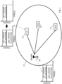
- Fig. 1 shows a diagram illustrating an example of a communication network using MC-NOMA in which examples of embodiments are implementable.
- a communication network control element or function 20 such as a BS or a gNB, controls communication in a network portion (such as a cell) 21.
- Reference signs 10, 12 and 13 denote communication elements or functions (UE 1, UE 2, ... UE k), respectively, which can communicate with the communication network vie the communication network control element or function 20.
- the transmit signal from the BS 20 and the received signal at the UEs is composed of a superposition of transmit signals of both UEs. This is indicated in the additional diagrams illustrated in Fig. 1 , especially the diagram linked to the BS 10, where a transmit signal composed of a part representing a small power allocation for UE 1 10 and part representing a large power allocation for UE 2 12 are indicated in frequency-power diagram).
- Multi-user signal separation is implemented at the UE side so that each UE is able to retrieve the signal dedicated to the corresponding UE so as to decode its own data.
- non-linear receivers such as maximum likelihood detection or SIC (Successive Interference Cancellation) is used.
- SIC Successessive Interference Cancellation
- the optimal order for decoding is in the order of the decreasing channel gain normalized by noise and inter-carrier interference power. Based on this order, it is possible that any user can correctly decode the signals of other users whose decoding order comes before the corresponding user.
- UE 1 10 when two UEs (i.e. UE 1 10 and US 2 12) are involved, UE 2 12 does not perform interference cancellation since it comes first in the decoding order.
- UE 1 10 first decodes the UE 2 signal, and subtracts its component from total received signal. Thus, it obtains its own signal component and decodes it, without interference from UE 2 signal. This is illustrated in the additional diagrams linked to the UE 1 10 in Fig. 1 .
- MC-NOMA achieves a better spectral efficiency and higher data rates than OMA schemes.
- the joint subcarrier and power allocation problem in NOMA is NP-hard to solve in general, due to complex impacts of signal superposition on each user's achievable data rates, as well as combinatorial constraints on the number of multiplexed users per subcarrier to mitigate error propagation.
- weighted sum-rate (WSR) maximization is especially important as it can achieve different tradeoffs between sum-rate performance and userfairness.
- WSR weighted sum-rate
- cellular power constraint is mostly used in downlink transmissions to represent the total transmit power budget available at the BS.
- individual power constraint sets a power limit independently for each user. The latter is more appropriate for uplink scenarios, nevertheless it can also be applied to the downlink.
- WSR maximization in OFDMA systems is polynomial time solvable if cellular power constraint is considered but strongly NP-hard with individual power constraints. It is also known that MC-NOMA with individual power constraints is strongly NP-hard.
- FTPC fractional transmit power control
- a time efficient iterative waterfilling heuristic can be used to solve the problem with equal weights.
- a nearly optimal WSR is achieved by a scheme using dynamic programming and Lagrangian duality techniques (also referred to as LDDP). This scheme has a high computational complexity, which is critical for systems with low latency requirements.
- MC-NOMA with cellular power constraint is polynomial time solvable or NP-hard.
- Known optimization schemes for this problem are either heuristics with no theoretical performance guarantee or algorithms with impractical computational complexity. For example, a greedy user selection and heuristic power allocation scheme based on difference-of-convex programming is proposed wherein a monotonic optimization is employed to develop an optimal resource allocation policy, which serves as benchmark due to its exponential complexity.
- LDDP can also be applied to cellular power constraint scenarios, but it has very high complexity as well.
- RRM radio resource management
- NOMA non-orthogonal multiple access
- NR 5G new radio
- Wi-Fi worldwide interoperability for microwave access (WiMAX), Bluetooth ® , personal communications services (PCS), ZigBee ® , wideband code division multiple access (WCDMA), systems using ultra-wideband (UWB) technology, mobile ad-hoc networks (MANETs), wired access, etc.
- WiMAX worldwide interoperability for microwave access
- Bluetooth ® personal communications services
- PCS personal communications services
- ZigBee ® wideband code division multiple access
- WCDMA wideband code division multiple access
- UWB ultra-wideband
- MANETs mobile ad-hoc networks
- wired access etc.
- a basic system architecture of a (tele)communication network including a mobile communication system may include an architecture of one or more communication networks including wireless access network subsystem(s) and core network(s).
- Such an architecture may include one or more communication network control elements or functions, access network elements, radio access network elements, access service network gateways or base transceiver stations, such as a base station (BS), an access point (AP), a NodeB (NB), an eNB or a gNB, a distributed or a centralized unit, which controls a respective coverage area or cell(s) and with which one or more communication stations such as communication elements, user devices or terminal devices, like a UE, or another device having a similar function, such as a modem chipset, a chip, a module etc., which can also be part of a station, an element, a function or an application capable of conducting a communication, such as a UE, an element or function usable in a machine-to-machine communication architecture, or attached as a separate
- a communication network architecture as being considered in examples of embodiments may also be able to communicate with other networks, such as a public switched telephone network or the Internet.
- the communication network may also be able to support the usage of cloud services for virtual network elements or functions thereof, wherein it is to be noted that the virtual network part of the telecommunication network can also be provided by non-cloud resources, e.g. an internal network or the like.
- network elements of an access system, of a core network etc., and/or respective functionalities may be implemented by using any node, host, server, access node or entity etc. being suitable for such a usage.
- a network function can be implemented either as a network element on a dedicated hardware, as a software instance running on a dedicated hardware, or as a virtualized function instantiated on an appropriate platform, e.g., a cloud infrastructure.
- a network element such as communication elements, like a UE, a terminal device, control elements or functions, such as access network elements, like a base station (BS), an gNB, a radio network controller, a core network control element or function, such as a gateway element, or other network elements or functions, as described herein, and any other elements, functions or applications may be implemented by software, e.g. by a computer program product for a computer, and/or by hardware.
- correspondingly used devices, nodes, functions or network elements may include several means, modules, units, components, etc. (not shown) which are required for control, processing and/or communication/signaling functionality.
- Such means, modules, units and components may include, for example, one or more processors or processor units including one or more processing portions for executing instructions and/or programs and/or for processing data, storage or memory units or means for storing instructions, programs and/or data, for serving as a work area of the processor or processing portion and the like (e.g. ROM, RAM, EEPROM, and the like), input or interface means for inputting data and instructions by software (e.g.
- a user interface for providing monitor and manipulation possibilities to a user (e.g. a screen, a keyboard and the like), other interface or means for establishing links and/or connections under the control of the processor unit or portion (e.g. wired and wireless interface means, radio interface means including e.g. an antenna unit or the like, means for forming a radio communication part etc.) and the like, wherein respective means forming an interface, such as a radio communication part, can be also located on a remote site (e.g. a radio head or a radio station etc.).
- processing portions should not be only considered to represent physical portions of one or more processors, but may also be considered as a logical division of the referred processing tasks performed by one or more processors.
- a so-called “liquid” or flexible network concept may be employed where the operations and functionalities of a network element, a network function, or of another entity of the network, may be performed in different entities or functions, such as in a node, host or server, in a flexible manner.
- a "division of labor" between involved network elements, functions or entities may vary case by case.
- a new RRM control scheme is proposed in which the problem to maximize the system's WSR in a DL MC NOMA system is solved by using two tasks, i.e. a single-carrier user selection (SCUS) procedure, which solves the user selection combinatorial problem, and a multi-carrier power control (MCPC) procedure to solve the multi-carrier power control problem.
- SCUS single-carrier user selection
- MCPC multi-carrier power control
- the optimization search space is restricted to a single subcarrier and the problem to be solved is to find a power allocation on the subcarrier satisfying certain multiplexing and successive interference cancellation (SIC) constraints.
- SIC multiplexing and successive interference cancellation
- MCPC aims to maximize the WSR for fixed subcarrier allocation for all subcarriers.
- Both procedures SCUS and MCPS are combinable into a joint subcarrier and power allocation (JSPA) procedure representing a a two-stage optimization procedure.
- JSPA joint subcarrier and power allocation
- the MCPC (given a fixed subcarrier allocation) sub-problem is non-convex.
- an optimal and low complexity algorithm (MCPC) based on projected gradient descent is provided, as described below.
- SCUS dynamic programming
- MCPC and SCUS represent examples of basic building blocks that can be applied in a wide range of resource allocation problems. That is, mathematical tools are provided based on the analysis of the separability property in MCPC and the combinatorial constraints in SCUS which are usable for other similar resource allocation optimization problems.
- examples of embodiments are applicable to a variable number of users. While conventional apporaches restrict the number of multiplexed users per subcarrier, denoted by M, to be equal to 2, examples of embodiments of the invention can be applied for an arbitrary number of superposed signals on each subcarrier, i.e., M ⁇ 1.
- M can be set depending on error propagation and decoding complexity concerns in practice, for example.
- a downlink multi-carrier NOMA system is considered composed of one base station (BS 20) serving K users (i.e. UEs 10, 12 and 13, in Fig. 1 , for example).
- BS 20 base station
- K users i.e. UEs 10, 12 and 13, in Fig. 1 , for example.
- the index set of users is denoted by K ⁇ 1 , ... , K
- the set of subcarriers is denoted by N ⁇ 1 , ... , N .
- p k n denotes the transmit power from the BS to user k ⁇ K on subcarrier n ⁇ N .
- User k is said to be active on subcarrier n if p k n > 0 , and inactive otherwise.
- gk be the channel gain between the BS and user k on subcarrier n
- ⁇ k n be the received noise power.
- the normalized noise power is defiend as ⁇ ⁇ k n ⁇ ⁇ k n / g k n .
- UEs In power domain NOMA, several users (UEs) are multiplexed on the same subcarrier using superposition coding, as described above.
- a common approach is, for example, to limit the number of superposed signals on each subcarrier to be no more than M .
- M The value of M is meant to characterize practical limitations of SIC due to decoding complexity and error propagation.
- the set of active users on subcarrier n is represented by U n ⁇ k ⁇ K : p k n > 0 .
- the aforementioned constraint can then be formulated as ⁇ n ⁇ , U n ⁇ M , where
- Each subcarrier is modeled, for example, as a multi-user Gaussian broadcast channel and SIC is applied at the receiver side to mitigate intra-band interference.
- a decoding order is considered comprising decoding users' signals from the highest to the lowest normalized noise power: ⁇ ⁇ ⁇ n 1 n ⁇ ⁇ ⁇ ⁇ n 2 n ⁇ ⁇ ⁇ ⁇ ⁇ ⁇ n K n
- User ⁇ n ( i ) first decodes the signals of users ⁇ n (1) to ⁇ n ( i - 1) and subtracts them from the superposed signal before decoding its own signal. Interference from users ⁇ n ( j ) for j > i is treated as noise.
- w ⁇ w 1 , ... , w K ⁇ be a sequence of K positive weights.
- the main focus is to solve the following joint subcarrier and power allocation optimization problem P: maximize p ⁇ k ⁇ K w k ⁇ n ⁇ N R k n p n , subject to C 1 : ⁇ k ⁇ K ⁇ n ⁇ N p k n ⁇ P max , C 2 : ⁇ k ⁇ K p k n ⁇ P max n , n ⁇ N , C 3 : p k n ⁇ 0 , k ⁇ K , n ⁇ N , C 4 : U n ⁇ M , n ⁇ N .
- the objective of P is to maximize the system's WSR. As discussed above, this objective function has received much attention since its weights w can be chosen to achieve different tradeoffs between sum-rate performance and fairness. The weights can also be tuned to perform fair resource allocation in a stable scheduling.
- constraint C1 represents the cellular power constraint, i.e., a total power budget P max at the BS 20.
- P max n a power limit of P max n for each subcarrier n is set. This is a common assumption in multi-carrier systems.
- Constraint C 3 ensures that the allocated powers remain non-negative. Due to decoding complexity and error propagation in SIC, the maximum number of multiplexed users per subcarrier is restricted to M in constraint C 4.
- Equality ( b ) comes from the definition (2).
- the weights w ⁇ n ( i ) are put inside the logarithm.
- ( d ) is obtained by combining the numerator of the i-th term with the denominator of the ( i - 1)-th term, for i ⁇ ⁇ 2, ..., K ⁇ .
- the active users set in C 4' is defined as U ′ n ⁇ i ⁇ 1 , ... K : x i n > x i + 1 n .
- Decomposing the joint subcarrier and power allocation problem P ' into smaller sub-problems allows to develop efficient algorithms by taking advantage of each sub-problem's particular structure. The technical details are given below.
- the optimization search space is restricted to a single subcarrier.
- auxiliary functions are introduced helping for the algorithm design.
- Fig. 10 illustrates an example of f j , i n which shows two general forms of function f j , i n .
- MaxF a pseudocode MaxF which is used to compute the maximum of f j , i n on [0, P ⁇ n ] following the result of Lemma 2.
- MaxF only requires a constant number of basic operations, therefore its complexity is O (1).
- J n w K W n g k n k ⁇ K ⁇ k n k ⁇ K .
- X [ m,j, i ] contains the corresponding optimal value of x j n , ... , x i n . Note that this is a scalar, as these variables are all equal from criterion (B). These arrays are computed recursively, i.e., their value at index ( m, j, i ) depends on their value either at ( m - 1 , j - 1 , j - 1), ( m, j - 1 , j - 1) or ( m, j - 1, i ).
- V [ m,j,i ] v 1 .
- v 1 is the sum of the optimal objective with at most m - 1 active users from indexes 1 to j - 1, i.e., V [ m - 1 , j - 1 , j - 1], and the individual contribution of the active user i, i.e., f j , i n MaxF j i J n P ⁇ n ⁇ f j , i n 0 .
- v 0 , v 1 and v 2 are assigned to V[m,j, i ], and the corresponding allocation is stored in X [ m,j, i].
- v 1 is only chosen if, in addition, conditions (4) and (5) are true as shown in line 26.
- V [ M, K, K ] is by definition the optimal value of P.
- the corresponding optimal allocation x n is retrieved in lines 43 to 46 by finding recursively the indexes ( m, j, i ) in U used to construct the solution until reaching (0,0,0).
- X [ m,j, i ] is assigned to variables x j n , ... , x i n .
- a detailed analysis of Algorithm 2 shows that SCUS's construction of V, X, U indeed match their definition.
- V [ M,K,K ] is by definition the optimal value of P'scus(n). The corresponding optimal allocation x n is retrieved in lines 40 to 46.
- P is transformed to P ' wherein the remaining active users on each subcarrier n are indexed by i n ⁇ 1 n , ... , U ′ n n .
- P' MCPC is formulated as a two-stage optimization problem. The first-stage is: maximize P ⁇ ⁇ n ⁇ N F n P ⁇ n P ′ MCPC subject to P ⁇ n ⁇ F , where P ⁇ n , for n ⁇ N , are intermediate variables representing each subcarrier's power budget. P ⁇ ⁇ P ⁇ 1 , ... , P ⁇ N denotes the power budget vector.
- the feasible set F ⁇ P ⁇ : ⁇ n ⁇ N P ⁇ n ⁇ P max and 0 ⁇ P ⁇ n ⁇ P max n , n ⁇ N is chosen to satisfy C1' and C2'.
- F n ( P ⁇ n ) is the optimal value of the second-stage (single-carroer power control SCPC):
- the first-stage P' MCPC consists in optimizing the allocated power budget P ⁇ n among subcarriers n ⁇ N . While the second-stage P' SCPC performs power allocation on each subcarrier n , with a given allocation U ′ n and power budget P ⁇ n .
- the second-stage P' SCPC can be solved, for example, by using the following Algorithm 3 (SCPC).
- variables x j n n , ... , x i n n are set equal to MaxF j n i n J n P ⁇ n at line 10.
- the optimality and complexity of this algorithm 3 are presented in the follwing Theorem 4.
- Theorem 4 Given subcarrier n ⁇ N and a power budget P n , algorithm SCPC computes the optimal single-carrier power control. Its worst case computational complexity is O U ′ n 2 .
- ⁇ l q i f l n n x l n n is optimal by construction.
- the convexity of P' MCPC is discussed in the following Lemma 5. That is, it is shown that is a convex set and ⁇ n ⁇ N F n is concave with respect to P ⁇ ⁇ F .
- the allocation returned by SCPC J n , U ′ n , P ⁇ n is equal to min x 1 n n P ⁇ n , ... , min x U ′ n n n P ⁇ n .
- Lemma 2 implies that f q n , q ′ n n is concave on 0 x q n n , therefore f q n , q ′ n n min x q n n P ⁇ n is concave in P ⁇ n ⁇ 0 P max n . It follows by summation that F n and ⁇ n ⁇ N F n F n are concave, which completes the proof.
- the second-stage optimal value F n ( P ⁇ n ), defined in P' SCPC is determined using SCPC as described in the auxiliary function in lines 12 to 13 of Algorithm 4.
- the search direction at line 4 can be found either using numerical methods or an exact gradient formula (see also the proof of Lemma 5).
- the step size ⁇ at line 5 can be tuned by backtracking line search or exact line search, for example. The latter is adopted to perform simulations, as discussed below.
- the projection of P + ⁇ ⁇ on the simplex at line 6 can be computed efficiently, the details of its implementation are omitted here.
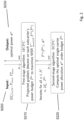
- Fig. 2 gives an overview of an example for the nested optimization that is designed to solve P' MCPC , wherein the above described Algorithms 3 and 4 are employed. It is to be noted that the example of Fig. 2 represents a case where the subcarrier allocation is given as a parameter.
- the output of the first stage algorithm representing an iteration for all subcarriers n ⁇ N of n, allocation U ′ n and power budget P ⁇ n is input into the second-stage algorithm SCPC.
- SCPC the optimal single-carrier power allocation x n under power budget P ⁇ n is computed.
- the output of the second-stage algorithm SCPC i.e. F n ( P ⁇ n ) and x n , are returned to the first-stage algorithm MCPC.
- computation of the received input is effected leading to an output of the optimal power x n for the respective subcarrier which is provided in S230.
- the first-stage algorithm MCPC can use the result achieved by processing (computing) the input of the second-stage algorithm SCPC for the next iteration (i.e. first-stage algorithm MCPC and second-stage algorithm SCPC form a loop), e.g. in case the condition in line 7 of algorithm 4 is not fulfilled.
- JSPA multi-carrier joint subscriber and power allocation
- JSPA represents efficient heuristic joint subcarrier and power allocation scheme which combines MCPC and SCUS. That is, basically, JSPA is similar to the two-stage MCPC approach depicted in Fig. 2 . However, there are some differences which will be discussed in the following.
- Fig. 3 gives an overview of an example for the JSPA procedure, wherein the above described Algorithms 2 and 4' are employed. It is to be noted that the example of Fig. 3 represents a case where the subcarrier allocation is not given as a parameter.
- the output of the first-stage algorithm representing an iteration for all subcarriers n ⁇ N of n , M and power budget P ⁇ n is input into the second-stage algorithm SCUS.
- the optimal single-carrier power allocation x n under power budget P ⁇ n is computed under the constraint U ′ n ⁇ M .
- the output of the second-stage algorithm SCUS i.e. F n ( P ⁇ n ) and x n , are returned to the first-stage algorithm MCPC.
- computation of the received input is effected leading to an output of the optimal power x n for the respective subcarrier which is provided in S330.
- the first-stage algorithm MCPC can use the result achieved by processing (computing) the input of the second-stage algorithm SCUS for the next iteration (i.e. first-stage algorithm MCPC and second-stage algorithm SCUS form a loop), e.g. in case the condition in line 7 of algorithm 4' is not fulfilled.
- a cell e.g. corresponding to cell 21 of Fig. 1
- K users e.g. UEs 10, 12, 13
- N 10
- Simulation results are indicated in the following as average values obtained over 1000 random instances. Simulation parameters and channel model are summarized in Table 1.
- Table 1 Simulation parameters Parameters Value Cell radius 250 m Minimum distance from user to BS 35 m Carrier frequency 2 GHz Path loss model 128.1 + 37.6log 10 d dB, d is in km Shadowing Log-normal, 8 dB standard deviation Fading Rayleigh fading with variance 1 Noise power spectral density -174 dBm/Hz System bandwidth W 5 MHz Number of subcarriers N 10 Number of users K 5 to 30 Total power budget P max 1 W Error tolerance ⁇ 10 -4 Parameter M 1 (OMA), 2 and 3 (NOMA)
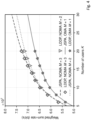
- Figs. 4 and 5 illustrate diagrams showing a comparison of results achievable by implementing the JSPA procedure as depicted, for example, in Fig. 3 according to some examples of embodiments and results achievable by using the LDDP procedure.
- weights w are generated uniformly at random in [0,1].
- the LDDP procedure requires to discretize the total power budget P max into J power levels.
- the performance loss of JSPA compared to LDDP is less than 0.8% for any number of users K . This indicates that JSPA also achieves near-optimal WSR, close to that of LDDP.
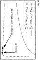
- Figs. 6 and 7 illustrate diagrams showing a comparison of results achievable by implementing the JSPA procedure as depicted, for example, in Fig. 3 according to some examples of embodiments and results achievable by using the FTPC procedure FTPC with greedy subcarrier allocation (the decay factor of FTPC is set to 0.4, which is a commonly set value).
- Fig. 6 shows a proportional fairness index defined as ⁇ k ⁇ K log R k mean / K
- Fig. 7 shows the sum-rate ⁇ k ⁇ K R k mean discussed below.
- the JSPA procedure outperforms the heuristic FTPC in both user fairness and sum-rate performance, and in both the OMA and NOMA systems.
- the WSR maximization problem in MC-NOMA with cellular power constraint is solved by providing a two-stage approach in which two sub-problems are solved optimally with low complexity.
- the user selection combinatorial problem is solved e.g. by SCUS (as proposed in Algorithm 2 discussed above, for example) on the basis of dynamic programming.
- the multi-carrier power control non-convex problem is solved by the two-stage algorithm MCPC (as proposed in Algorithm 4 or 4' discussed above, for example), which uses separability property and gradient descent methods.
- MCPC as proposed in Algorithm 4 or 4' discussed above, for example
- JSPA is proposed to tackle the joint subcarrier and power allocation problem.
- Fig. 8 shows a flow chart of a processing executed by a communication network control element or function according to some examples of embodiments, which conducts a radio resource management control for a communication to at least one communication element or function (UE) in a communication network by using a plurality of subcarriers.
- the communication network control element or function is configured to use NOMA for communicating with at least one communication element or function.
- input parameters for the processing are acquired.
- a set of a maximum total power budget, a maximum power budget for each subcarrier, and at least one of a maximum number of multiplexed users per subcarrier and a number of allocated users per subcarrier is acquired.
- the input parameters are processed by using a first-stage procedure for maximizing a weighted sum-rate for a fixed subcarrier allocation for all subcarriers, and a second-stage procedure for determining a power allocation for a single subcarrier under consideration of specified multiplexing and interference cancellation constraints.
- a processing result output from the first-stage procedure is input into the second-stage procedure, and a processing result output from the second-stage procedure is returned to the first-stage procedure.
- the maximum total power budget, the maximum power budget for each subcarrier, and the maximum number of multiplexed users per subcarrier is processed by using a projected gradient descent on each power budget for each subcarrier to maximize the weighted sum-rate.
- the first-stage procedure is based, for example, on the MCPC procedure described above, wherein e.g. one of Algorithm 4' can be employed. From the first-stage procedure to the second stage procedure, an indication of the subcarrier to be considered, the maximum number of multiplexed users per subcarrier and the power budget for the indicated subcarrier are output.
- the indication of the subcarrier to be considered, the maximum number of multiplexed users per subcarrier and the power budget for the indicated subcarrier for computing an optimal single-carrier power allocation under the power budget for the indicated subcarrier are processed. Furthermore, in the second-stage procedure, a constraint indicating that the number of allocated users is equal to or less than the maximum number of multiplexed users per subcarrier is considered.
- the second-stage procedure is based, for example, on the SCUS procedure described above, wherein e.g. Algorithm 2 can be employed.
- the computed optimal single-carrier power allocation is output, and/or the parameter for determining the weighted sum-rate and the computed optimal single-carrier power allocation are used in a next iteration for providing an input into the second-stage procedure by updating parameters used in the processing of the first-stage procedure.
- the processing in the first-stage procedure and the second stage procedure is based on maximize p ⁇ k ⁇ K w k ⁇ n ⁇ N R k n p n , subject to C 1 : ⁇ k ⁇ K ⁇ n ⁇ N p k n ⁇ P max , C 2 : ⁇ k ⁇ K p k n ⁇ P max n , n ⁇ N , C 3 : p k n ⁇ 0 , k ⁇ K , n ⁇ N , C 4 : U n ⁇ M , n ⁇ N .
- w K is a sequence of K positive weights
- R k n p n is a maximum achievable data rage of user k on a subcarrier n
- P represents a joint subcarrier and power allocation optimization problem P
- C 1 represents a cellular power constraint in form of the total power budget
- C 2 sets a power limit for each subcarrier n
- C 3 defines that the allocated powers remain non-negative
- C4 restricts the maximum number of multiplexed users per subcarrier to M.
- a power setting for at least one subcarrier is output.
- Fig. 9 shows a diagram of a network element or function representing a communication network control element or function according to some examples of embodiments, e.g. the BS 20 of Fig. 1 , which is configured to conduct a radio resource management control procedure as described in connection with some of the examples of embodiments.
- the communication network control element or function like the BS 20 of Fig. 1 , may include further elements or functions besides those described herein below.
- the element or function may be also another device or function having a similar task, such as a chipset, a chip, a module, an application etc., which can also be part of a network element or attached as a separate element to a network element, or the like. It should be understood that each block and any combination thereof may be implemented by various means or their combinations, such as hardware, software, firmware, one or more processors and/or circuitry.
- the communication network control element or function shown in Fig. 9 may include a processing circuitry, a processing function, a control unit or a processor 201, such as a CPU or the like, which is suitable for executing instructions given by programs or the like related to the paging control procedure.
- the processor 201 may include one or more processing portions or functions dedicated to specific processing as described below, or the processing may be run in a single processor or processing function. Portions for executing such specific processing may be also provided as discrete elements or within one or more further processors, processing functions or processing portions, such as in one physical processor like a CPU or in one or more physical or virtual entities, for example.
- Reference sign 202 and 203 denote input/output (I/O) units or functions (interfaces) connected to the processor or processing function 201.
- the I/O units 202 may be used for communicating with a communication element or function like the UEs 10, 12, 13, as described in connection with Fig. 1 , for example.
- the I/O units 203 may be used for communicating with other network element, like core network elements.
- the I/O units 202 and 203 may be a combined unit including communication equipment towards several entities, or may include a distributed structure with a plurality of different interfaces for different entities.
- Reference sign 204 denotes a memory usable, for example, for storing data and programs to be executed by the processor or processing function 201 and/or as a working storage of the processor or processing function 201. It is to be noted that the memory 204 may be implemented by using one or more memory portions of the same or different type of memory.
- the processor or processing function 201 is configured to execute processing related to the above described paging control processing.
- the processor or processing circuitry or function 201 includes one or more of the following sub-portions.
- Sub-portion 2011 is a processing portion which is usable as a portion for acquiring input data.
- the portion 2011 may be configured to perform processing according to S800 of Fig. 8 .
- the processor or processing circuitry or function 201 may include a sub-portion 2012 usable as a portion for conducting a processing using the first-stage and second-stage procedures.
- the portion 2012 may be configured to perform a processing according to S810 of Fig. 8 .
- the processor or processing circuitry or function 201 may include a sub-portion 2013 usable as a portion for outputting the power setting value.
- the portion 2013 may be configured to perform a processing according to S820 of Fig. 8 .
- an apparatus for use by a communication network control element or function configured to conduct a radio resource management control for a communication to at least one communication element or function in a communication network by using a plurality of subcarriers comprising: means configured to acquire input parameters; means configured to process the input parameters by using a first-stage procedure for maximizing a weighted sum-rate for a fixed subcarrier allocation for all subcarriers, and a second-stage procedure for determining a power allocation for a single subcarrier under consideration of specified multiplexing and interference cancellation constraints, wherein a processing result output from the first-stage procedure is input into the second-stage procedure, and a processing result output from the second-stage procedure is returned to the first-stage procedure; and means configured to output, on the basis of results of the processing in the first-stage procedure and the second-stage procedure, a power setting for at least one subcarrier.
- the above defined apparatus may further comprise means for conducting at least one of the processing defined in the above described methods, for example a method according to that described in connection with Fig 8 .
- a non-transitory computer readable medium comprising program instructions for causing an apparatus to perform at least the following: conducting a radio resource management control for a communication to at least one communication element or function in a communication network by using a plurality of subcarriers; acquiring input parameters; processing the input parameters by using a first-stage procedure for maximizing a weighted sum-rate for a fixed subcarrier allocation for all subcarriers, and a second-stage procedure for determining a power allocation for a single subcarrier under consideration of specified multiplexing and interference cancellation constraints, wherein a processing result output from the first-stage procedure is input into the second-stage procedure, and a processing result output from the second-stage procedure is returned to the first-stage procedure; and outputting, on the basis of results of the processing in the first-stage procedure and the second-stage procedure, a power setting for at least one subcarrier.
Landscapes
- Engineering & Computer Science (AREA)
- Signal Processing (AREA)
- Computer Networks & Wireless Communication (AREA)
- Quality & Reliability (AREA)
- Mobile Radio Communication Systems (AREA)
Description
- Examples of embodiments relate to apparatuses, methods, computer program products and computer-readable media usable for conducting radio resource management in a communication network using non-orthogonal multiple access (NOMA), and in particular to apparatuses, methods, systems, computer programs, computer program products and (non-transitory) computer-readable media usable for maximizing a weighted sum rate in a multi-carrier NOMA with cellular power constraints.
- The following description of background art may include insights, discoveries, understandings or disclosures, or associations, together with disclosures not known to the relevant prior art, to at least some examples of embodiments of the present invention but provided by the invention. Some of such contributions of the invention may be specifically pointed out below, whereas other of such contributions of the invention will be apparent from the related context.
- Salaunen at al, "Optimal Joint Subcarrier and Power Allocation in NOMA Is Strongly NP-Hard", 2018 IEEE International Conference on Communications (ICC), 20180520 IEEE, discusses the complexity of solving the joint subcarrier and power allocation problem in NOMA systems, and identifies special cases of the NP-hard problem which are solvable in polynomial time. It is shown that computing the optimal solution to the joint subcarrier and power allocation problem can be reduced to a power control problem, which in turn can be solved for a fixed and arbitrary chosen subcarrier allocation by convex programming techniques.
- Guo Shaozhen et al, "Distributed optimization for downlink broadband small cell networks", 2015 IEEE International Conference on Communications (ICC), 20150608 IEEE, presents a distributed algorithm for optimizing power of subcarriers jointly. A first algorithm computes the power allocation P, which is then input to a second algorithm, to find the subcarrier allocation matrix.
- Zhang et al, "Joint Subcarrier Assignment and Downlink-Uplink Time-Power Allocation for Wireless Powered OFDM-NOMA Systems", 2018 10th International Conference on Wireless Communications and Signal Processing (WCSP), 20181018 IEEE, proposes optimization of subcarrier assignment with fairness, based on which an optimal solution to joint downlink-uplink time-power allocation problem is discussed.
- The following meanings for the abbreviations used in this specification apply:
- 3GPP
- 3rd Generation Partnership Project
- 4G
- fourth generation
- 5G
- fifth generation
- BS
- base station
- CN
- core network
- CPU
- central processing unit
- DL
- downlink
- eNB
- evolved node B
- ETSI
- European Telecommunications Standards Institute
- FTPC
- fractional transmit power control
- gNB
- next generation node B
- JSPA
- joint subcarrier and power allocation
- LDDP
- Lagrangian duality and dynamic programming
- LTE
- Long Term Evolution
- LTE-A
- LTE Advanced
- MC-NOMA
- multi carrier NOMA
- MCPC
- multi carrier power control
- NOMA
- non-orthogonal multiple access
- NG
- new generation
- NP
- non-deterministic polynomial acceptable problems
- NR
- new radio
- OFDMA
- orthogonal frequency-division multiple access
- OMA
- orthogonal multiple access
- QoS
- quality of service
- RRM
- radio resource management
- SCUS
- single carrier user selection
- SIC
- successive interference cancellation
- UE
- user equipment
- UL
- uplink
- UMTS
- universal mobile telecommunication system
- WSR
- weighted sum-rate
- The object is solved by the subject-matter covered by the independent claims. Preferred embodiments are defined in the dependent claims.
- According to an example of an embodiment, there is provided, for example, an apparatus for use by a communication network control element or function configured to conduct a radio resource management control for a communication to at least one communication element or function in a communication network by using a plurality of subcarriers, the apparatus comprising at least one processing circuitry, and at least one memory for storing instructions to be executed by the processing circuitry, wherein the at least one memory and the instructions are configured to, with the at least one processing circuitry, cause the apparatus at least: to acquire input parameters; to process the input parameters by using a first-stage procedure for maximizing a weighted sum-rate for a fixed subcarrier allocation for all subcarriers, and a second-stage procedure for determining a power allocation for a single subcarrier under consideration of specified multiplexing and interference cancellation constraints, wherein a processing result output from the first-stage procedure is input into the second-stage procedure, and a processing result output from the second-stage procedure is returned to the first-stage procedure; and to output, on the basis of results of the processing in the first-stage procedure and the second-stage procedure, a power setting for at least one subcarrier.
- Furthermore, according to an example of an embodiment, there is provided, for example, a method for use in a communication network control element or function configured to conduct a radio resource management control for a communication to at least one communication element or function in a communication network by using a plurality of subcarriers, the method comprising acquiring input parameters; processing the input parameters by using a first-stage procedure for maximizing a weighted sum-rate for a fixed subcarrier allocation for all subcarriers, and a second-stage procedure for determining a power allocation for a single subcarrier under consideration of specified multiplexing and interference cancellation constraints, wherein a processing result output from the first-stage procedure is input into the second-stage procedure, and a processing result output from the second-stage procedure is returned to the first-stage procedure; and outputting, on the basis of results of the processing in the first-stage procedure and the second-stage procedure, a power setting for at least one subcarrier.
- These examples include the following features:
- as the input parameters, a maximum total power budget, a maximum power budget for each subcarrier, and at least one of a maximum number of multiplexed users per subcarrier and a number of allocated users per subcarrier may be acquired;
- in the first-stage procedure, as the input parameters, the maximum total power budget, the maximum power budget for each subcarrier, and the maximum number of multiplexed users per subcarrier may be processed, by using a projected gradient descent on each power budget for each subcarrier to maximize the weighted sum-rate; from the first-stage procedure to the second stage procedure, an indication of the subcarrier to be considered, the maximum number of multiplexed users per subcarrier and the power budget for the indicated subcarrier may be output; in the second-stage procedure, the indication of the subcarrier to be considered, the maximum number of multiplexed users per subcarrier and the power budget for the indicated subcarrier may be processed for computing an optimal single-carrier power allocation under the power budget for the indicated subcarrier and by considering a constraint indicating that the number of allocated users is equal to or less than the maximum number of multiplexed users per subcarrier; from the second-stage procedure to the first-stage procedure, an indication of the subcarrier to be considered, a parameter for determining the weighted sum-rate and the computed optimal single-carrier power allocation may be output; process, in the first-stage procedure, the parameter for determining the weighted sum-rate and the computed optimal single-carrier power allocation may be processed;
- According to further refinements, these examples may include one or more of the following features:
- in the processing in the first-stage procedure of the parameter for determining the weighted sum-rate and the computed optimal single-carrier power allocation, at least one of outputting the computed optimal single-carrier power allocation, and using the parameter for determining the weighted sum-rate and the computed optimal single-carrier power allocation in a next iteration for providing an input into the second-stage procedure by updating parameters used in the processing of the first-stage procedure may be conducted;
- the processing in the first-stage procedure and the second stage procedure may be based on


- the communication network control element or function may be configured to use at least one of non-orthogonal muliple access and orthogonal multiple access for communicating with the at least one communication element or function.
- In addition, according to embodiments, there is provided, for example, a computer program product for a computer, including software code portions for performing the steps of the above defined methods, when said product is run on the computer. The computer program product may include a computer-readable medium on which said software code portions are stored. Furthermore, the computer program product may be directly loadable into the internal memory of the computer and/or transmittable via a network by means of at least one of upload, download and push procedures.
- Some embodiments of the present invention are described below, by way of example only, with reference to the accompanying drawings, in which:
-
Fig. 1 shows a diagram illustrating an example of a communication network using MC-NOMA in which examples of embodiments are implementable; -
Fig. 2 shows a diagram for explaining a MCPC procedure according to some examples of embodiments; -
Fig. 3 shows a diagram for explaining a JSPA procedure according to some examples of embodiments; -
Fig. 4 shows a diagram for illustrating a comparison of results achievable by implementing a JSPA procedure according to some examples of embodiments and results achievable by a LDDP procedure; -
Fig. 5 shows a diagram for illustrating a comparison of results achievable by implementing a JSPA procedure according to some examples of embodiments and results achievable by a LDDP procedure; -
Fig. 6 shows a diagram for illustrating a comparison of results achievable by implementing a JSPA procedure according to some examples of embodiments and results achievable by a FTPC procedure; -
Fig. 7 shows a diagram for illustrating a comparison of results achievable by implementing a JSPA procedure according to some examples of embodiments and results achievable by a FTPC procedure; -
Fig. 8 shows a flow chart of a processing executed by a communication network control element or function according to some examples of embodiments; -
Fig. 9 shows a diagram of a network element or function representing a communication network control element or function according to some examples of embodiments; and -
Fig. 10 shows a diagram illustrating a function used for algorithm design. - In the last years, an increasing extension of communication networks, e.g. of wire based communication networks, such as the Integrated Services Digital Network (ISDN), Digital Subscriber Line (DSL), or wireless communication networks, such as the cdma2000 (code division multiple access) system, cellular 3rd generation (3G) like the Universal Mobile Telecommunications System (UMTS), fourth generation (4G) communication networks or enhanced communication networks based e.g. on Long Term Evolution (LTE) or Long Term Evolution-Advanced (LTE-A), fifth generation (5G) communication networks, cellular 2nd generation (2G) communication networks like the Global System for Mobile communications (GSM), the General Packet Radio System (GPRS), the Enhanced Data Rates for Global Evolution (EDGE), or other wireless communication system, such as the Wireless Local Area Network (WLAN), Bluetooth or Worldwide Interoperability for Microwave Access (WiMAX), took place all over the world. Various organizations, such as the European Telecommunications Standards Institute (ETSI), the 3rd Generation Partnership Project (3GPP), Telecoms & Internet converged Services & Protocols for Advanced Networks (TISPAN), the International Telecommunication Union (ITU), 3rd Generation Partnership Project 2 (3GPP2), Internet Engineering Task Force (IETF), the IEEE (Institute of Electrical and Electronics Engineers), the WiMAX Forum and the like are working on standards or specifications for telecommunication network and access environments.
- Basically, for properly establishing and handling a communication between two or more end points (e.g. communication stations or elements, such as terminal devices, user equipments (UEs), or other communication network elements, a database, a server, host etc.), one or more network elements or functions (e.g. virtualized network functions), such as communication network control elements or functions, for example access network elements like access points, radio base stations, relay stations, eNBs, gNBs etc., and core network elements or functions, for example control nodes, support nodes, service nodes, gateways, user plane functions, access and mobility functions etc., may be involved, which may belong to one communication network system or different communication network systems.
- In legacy communication networks, such as third generation (3G) cellular networks, frequency division multiple access (FDMA), time division multiple access and code division multiple access were introduced, respectively. In 4G networks like LTE and LTE-A, techniques like orthogonal frequency division multiple access (OFDMA) are adopted as an OMA approach, allowing to avoid mutual interference among users and providing therefore good system-level performance even with simplified receivers.
- However, future radio access systems, such as 5G systems, have increased demands, for example due to an increasing demand of mobile Internet and the Internet of Things which poses challenging requirements for 5G wireless communications, such as high spectral efficiency and massive connectivity.
- As a possible technology allowing to meet these demands, non-orthogonal multiple access (NOMA) is introduced. NOMA represents a multiple access technique allowing to significantly improve the spectral efficiency of mobile communication networks, and it outperforms orthogonal schemes, such as OFDMA, in terms of spectral efficiency and massive connectivity.
- Basically, NOMA is based on the usage of signals that possess significant differences e.g. in power levels. It is then possible to totally isolate the one signal (e.g. the high level signal) at the receiver and then cancel it out to leave only the other signal (e.g. the low level signal). In this way, NOMA exploits the path loss differences amongst users, although it does need additional processing power in the receiver.
- NOMA schemes can be classified into two types: power-domain multiplexing and code-domain multiplexing. In the following, principles for power-domain multiplexing are described. Here, different users are allocated different power coefficients according to their channel conditions in order to achieve a high system performance. In particular, multiple users' information signals are superimposed at the transmitter side. At the receiver side successive interference cancellation (SIC) is applied for decoding the signals one by one until the desired user's signal is obtained, providing a good trade-off between the throughput of the system and the user fairness. Power-domain multiplexing is easy to implement as considerable changes are not required on the existing networks. Also, it does not require additional bandwidth in order to improve spectral efficiency.
-
Fig. 1 shows a diagram illustrating an example of a communication network using MC-NOMA in which examples of embodiments are implementable. Specifically, inFig. 1 , a communication network control element orfunction 20, such as a BS or a gNB, controls communication in a network portion (such as a cell) 21. Reference signs 10, 12 and 13 denote communication elements or functions (UE 1,UE 2, ... UE k), respectively, which can communicate with the communication network vie the communication network control element orfunction 20. - In downlink NOMA, the transmit signal from the
BS 20 and the received signal at the UEs (in the following,UE 1 10 andUE 2 20 are considered, but the principles described below are also application in case of more than two UEs) is composed of a superposition of transmit signals of both UEs. This is indicated in the additional diagrams illustrated inFig. 1 , especially the diagram linked to theBS 10, where a transmit signal composed of a part representing a small power allocation forUE 1 10 and part representing a large power allocation forUE 2 12 are indicated in frequency-power diagram). - Multi-user signal separation is implemented at the UE side so that each UE is able to retrieve the signal dedicated to the corresponding UE so as to decode its own data. For example, non-linear receivers such as maximum likelihood detection or SIC (Successive Interference Cancellation) is used. In case of SIC, the optimal order for decoding is in the order of the decreasing channel gain normalized by noise and inter-carrier interference power. Based on this order, it is possible that any user can correctly decode the signals of other users whose decoding order comes before the corresponding user.
- Considering the case shown in
Fig. 1 , when two UEs (i.e.UE 1 10 andUS 2 12) are involved,UE 2 12 does not perform interference cancellation since it comes first in the decoding order.UE 1 10 first decodes theUE 2 signal, and subtracts its component from total received signal. Thus, it obtains its own signal component and decodes it, without interference fromUE 2 signal. This is illustrated in the additional diagrams linked to theUE 1 10 inFig. 1 . - As described above, the principle of MC-NOMA is to multiplex several users on the same subcarrier by performing signals superposition at the transmitter side. Successive interference cancellation (SIC) is applied at the receiver side to mitigate interference between superposed signals. MC-NOMA achieves a better spectral efficiency and higher data rates than OMA schemes.
- Careful optimization of the transmit powers is required to control the intra-carrier interference of superposed signals and maximize the achievable data rates. Besides, due to error propagation and decoding complexity concerns in practice, subcarrier allocation for each transmission also needs to be optimized. As a consequence, joint subcarrier and power allocation problems in NOMA have received much attention.
- The joint subcarrier and power allocation problem in NOMA is NP-hard to solve in general, due to complex impacts of signal superposition on each user's achievable data rates, as well as combinatorial constraints on the number of multiplexed users per subcarrier to mitigate error propagation. In this class of problems, weighted sum-rate (WSR) maximization is especially important as it can achieve different tradeoffs between sum-rate performance and userfairness. One may also consider to use the weights to perform fair resource allocation in a stable scheduling.
- Conventionally, two types of power constraints are considered. On the one hand, cellular power constraint is mostly used in downlink transmissions to represent the total transmit power budget available at the BS. On the other hand, individual power constraint sets a power limit independently for each user. The latter is more appropriate for uplink scenarios, nevertheless it can also be applied to the downlink.
- It is known that WSR maximization in OFDMA systems is polynomial time solvable if cellular power constraint is considered but strongly NP-hard with individual power constraints. It is also known that MC-NOMA with individual power constraints is strongly NP-hard. Several algorithms are developed to perform subcarrier and/or power allocation in this setting. For example, fractional transmit power control (FTPC) is a simple heuristic that allocates a fraction of the total power budget to each user based on their channel condition. Also approaches where heuristic user pairing strategies and iterative resource allocation algorithms are studied for uplink transmissions are known. A time efficient iterative waterfilling heuristic can be used to solve the problem with equal weights. A nearly optimal WSR is achieved by a scheme using dynamic programming and Lagrangian duality techniques (also referred to as LDDP). This scheme has a high computational complexity, which is critical for systems with low latency requirements.
- It is not known if MC-NOMA with cellular power constraint is polynomial time solvable or NP-hard. Known optimization schemes for this problem are either heuristics with no theoretical performance guarantee or algorithms with impractical computational complexity. For example, a greedy user selection and heuristic power allocation scheme based on difference-of-convex programming is proposed wherein a monotonic optimization is employed to develop an optimal resource allocation policy, which serves as benchmark due to its exponential complexity. LDDP can also be applied to cellular power constraint scenarios, but it has very high complexity as well.
- In view of the above, improvements in radio resource management (RRM) in a non-orthogonal multiple access (NOMA) system, which is considered e.g. in connection with 5G new radio (NR), are possible. Specifically, improvements can be made with regard to the WSR maximization problem in a downlink MC NOMA system with cellular power constraint, in order to avoid problems in large systems due to high computational complexity of existing solutions.
- In the following, different exemplifying embodiments will be described using, as an example of a communication network to which examples of embodiments may be applied, a communication network architecture based on 3GPP standards for a communication network, such as a 5G, using NOMA, without restricting the embodiments to such an architecture, however. It is obvious for a person skilled in the art that the embodiments may also be applied to other kinds of communication networks having suitable means by adjusting parameters and procedures appropriately, e.g. Wi-Fi, worldwide interoperability for microwave access (WiMAX), Bluetooth®, personal communications services (PCS), ZigBee®, wideband code division multiple access (WCDMA), systems using ultra-wideband (UWB) technology, mobile ad-hoc networks (MANETs), wired access, etc.. Furthermore, without loss of generality, the description of some examples of embodiments is related to a mobile communication network, but principles of the invention can be extended and applied to any other type of communication network, such as a wired communication network.
- The following examples and embodiments are to be understood only as illustrative examples. Although the specification may refer to "an", "one", or "some" example(s) or embodiment(s) in several locations, this does not necessarily mean that each such reference is related to the same example(s) or embodiment(s), or that the feature only applies to a single example or embodiment. Single features of different embodiments may also be combined to provide other embodiments. Furthermore, terms like "comprising" and "including" should be understood as not limiting the described embodiments to consist of only those features that have been mentioned; such examples and embodiments may also contain features, structures, units, modules etc. that have not been specifically mentioned.
- A basic system architecture of a (tele)communication network including a mobile communication system where some examples of embodiments are applicable may include an architecture of one or more communication networks including wireless access network subsystem(s) and core network(s). Such an architecture may include one or more communication network control elements or functions, access network elements, radio access network elements, access service network gateways or base transceiver stations, such as a base station (BS), an access point (AP), a NodeB (NB), an eNB or a gNB, a distributed or a centralized unit, which controls a respective coverage area or cell(s) and with which one or more communication stations such as communication elements, user devices or terminal devices, like a UE, or another device having a similar function, such as a modem chipset, a chip, a module etc., which can also be part of a station, an element, a function or an application capable of conducting a communication, such as a UE, an element or function usable in a machine-to-machine communication architecture, or attached as a separate element to such an element, function or application capable of conducting a communication, or the like, are capable to communicate via one or more channels via one or more communication beams for transmitting several types of data in a plurality of access domains. Furthermore, core network elements or network functions, such as gateway network elements/functions, mobility management entities, a mobile switching center, servers, databases and the like may be included.
- The general functions and interconnections of the described elements and functions, which also depend on the actual network type, are known to those skilled in the art and described in corresponding specifications, so that a detailed description thereof is omitted herein. However, it is to be noted that several additional network elements and signaling links may be employed for a communication to or from an element, function or application, like a communication endpoint, a communication network control element, such as a server, a gateway, a radio network controller, and other elements of the same or other communication networks besides those described in detail herein below.
- A communication network architecture as being considered in examples of embodiments may also be able to communicate with other networks, such as a public switched telephone network or the Internet. The communication network may also be able to support the usage of cloud services for virtual network elements or functions thereof, wherein it is to be noted that the virtual network part of the telecommunication network can also be provided by non-cloud resources, e.g. an internal network or the like. It should be appreciated that network elements of an access system, of a core network etc., and/or respective functionalities may be implemented by using any node, host, server, access node or entity etc. being suitable for such a usage. Generally, a network function can be implemented either as a network element on a dedicated hardware, as a software instance running on a dedicated hardware, or as a virtualized function instantiated on an appropriate platform, e.g., a cloud infrastructure.
- Furthermore, a network element, such as communication elements, like a UE, a terminal device, control elements or functions, such as access network elements, like a base station (BS), an gNB, a radio network controller, a core network control element or function, such as a gateway element, or other network elements or functions, as described herein, and any other elements, functions or applications may be implemented by software, e.g. by a computer program product for a computer, and/or by hardware.
- For executing their respective processing, correspondingly used devices, nodes, functions or network elements may include several means, modules, units, components, etc. (not shown) which are required for control, processing and/or communication/signaling functionality. Such means, modules, units and components may include, for example, one or more processors or processor units including one or more processing portions for executing instructions and/or programs and/or for processing data, storage or memory units or means for storing instructions, programs and/or data, for serving as a work area of the processor or processing portion and the like (e.g. ROM, RAM, EEPROM, and the like), input or interface means for inputting data and instructions by software (e.g. floppy disc, CD-ROM, EEPROM, and the like), a user interface for providing monitor and manipulation possibilities to a user (e.g. a screen, a keyboard and the like), other interface or means for establishing links and/or connections under the control of the processor unit or portion (e.g. wired and wireless interface means, radio interface means including e.g. an antenna unit or the like, means for forming a radio communication part etc.) and the like, wherein respective means forming an interface, such as a radio communication part, can be also located on a remote site (e.g. a radio head or a radio station etc.). It is to be noted that in the present specification processing portions should not be only considered to represent physical portions of one or more processors, but may also be considered as a logical division of the referred processing tasks performed by one or more processors.
- It should be appreciated that according to some examples, a so-called "liquid" or flexible network concept may be employed where the operations and functionalities of a network element, a network function, or of another entity of the network, may be performed in different entities or functions, such as in a node, host or server, in a flexible manner. In other words, a "division of labor" between involved network elements, functions or entities may vary case by case.
- According to embodiments of the invention, a new RRM control scheme is proposed in which the problem to maximize the system's WSR in a DL MC NOMA system is solved by using two tasks, i.e. a single-carrier user selection (SCUS) procedure, which solves the user selection combinatorial problem, and a multi-carrier power control (MCPC) procedure to solve the multi-carrier power control problem. Specifically, in SCUS, the optimization search space is restricted to a single subcarrier and the problem to be solved is to find a power allocation on the subcarrier satisfying certain multiplexing and successive interference cancellation (SIC) constraints. On the other hand, MCPC aims to maximize the WSR for fixed subcarrier allocation for all subcarriers.
- Both procedures SCUS and MCPS are combinable into a joint subcarrier and power allocation (JSPA) procedure representing a a two-stage optimization procedure. By means of this, the system's WSR can be maximized, i.e. a near-optimal sum-rate and user fairness can be achieved with an decreased computational effort.
- That is, according to examples of embodiments, two polynomial time solvable sub-problems are processed. The MCPC (given a fixed subcarrier allocation) sub-problem is non-convex. By taking advantage of its separability property, according to examples of embodiments, an optimal and low complexity algorithm (MCPC) based on projected gradient descent is provided, as described below. Furthermore, the SCUS sub-problem is a non-convex mixed-integer problem that is solved, according to examples of embodiments, by using dynamic programming (SCUS).
- Furthermore, according to example of embodiments, a procedure is provided regarding how each sub-problem's particular structure can facilitate the algorithm design. In that respect, the above MCPC and SCUS represent examples of basic building blocks that can be applied in a wide range of resource allocation problems. That is, mathematical tools are provided based on the analysis of the separability property in MCPC and the combinatorial constraints in SCUS which are usable for other similar resource allocation optimization problems.
- It is to be noted that examples of embodiments are applicable to a variable number of users. While conventional apporaches restrict the number of multiplexed users per subcarrier, denoted by M, to be equal to 2, examples of embodiments of the invention can be applied for an arbitrary number of superposed signals on each subcarrier, i.e., M ≥ 1. The value of M can be set depending on error propagation and decoding complexity concerns in practice, for example.
- In order to solve the general WSR maximization problem, an efficient heuristic is proposed by combining MCPC and SCUS into the JSPA procedure. Thus, a near-optimal sum-rate and user fairness can be achieved, wherein a significant improvement in performance over OMA is still provided.
- In the following, examples of embodiments are described in further detail by referring to a system model and notations being used, a formulation of the underlying WSR problem, a description of the used algorithms and an analysis of their optimality and complexity, which is examplified by illustrating corresponding numerical results in comparison to existing approaches like LDDP and FTPC in order to highlight sum-rate and fairness performance, as well as the computational complexity of the respective approaches.
- With regard to the system model and notations, a general example for a NOMA system as shown in
Fig. 1 is used as a basis. That is, in the following, a downlink multi-carrier NOMA system is considered composed of one base station (BS 20) serving K users (i.e.UEs Fig. 1 , for example). - The index set of users is denoted by


- Let


- In power domain NOMA, several users (UEs) are multiplexed on the same subcarrier using superposition coding, as described above. A common approach is, for example, to limit the number of superposed signals on each subcarrier to be no more than M. The value of M is meant to characterize practical limitations of SIC due to decoding complexity and error propagation. The set of active users on subcarrier n is represented by
 ,
,

- The SIC decoding order on subcarrier n is usually defined as a permutation over the active users on n, i.e.,
 , i.e.,


- According to examples of embodiments, a decoding order is considered comprising decoding users' signals from the highest to the lowest normalized noise power:

- User πn (i) first decodes the signals of users πn (1) to πn (i - 1) and subtracts them from the superposed signal before decoding its own signal. Interference from users πn (j) for j > i is treated as noise. The maximum achievable data rate of user k on subcarrier n is given by Shannon capacity:


- Next, the problem to be solved in the procedure according to examples of embodiments is formulated.
- Let w = {w 1, ... , wK } be a sequence of K positive weights. The main focus is to solve the following joint subcarrier and power allocation optimization problem P:

- The objective of P is to maximize the system's WSR. As discussed above, this objective function has received much attention since its weights w can be chosen to achieve different tradeoffs between sum-rate performance and fairness. The weights can also be tuned to perform fair resource allocation in a stable scheduling. Note that constraint C1 represents the cellular power constraint, i.e., a total power budget Pmax at the
BS 20. In constraint C2, a power limit of
- For a further detailed explanation, the following change of variables is considered:

- It is defined that


- A problem equivalent to the above defined problem P is considered in the following helping theorem (referred to as Lemma)
Lemma 1 as equivalent problem P'. That is problem P is equivalent to problem P' formulated below:


- This is proved as follows.
- The objective of P can be written as:

- Equality (b) comes from the definition (2). At (c), the weights w πn(i) are put inside the logarithm. Finally, (d) is obtained by combining the numerator of the i-th term with the denominator of the (i - 1)-th term, for i ∈ {2, ...,K}.
- The constant term




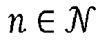

- The advantage of this formulation P' is that it exhibits a separable objective function in both dimensions i ∈ {1, ..., K} and


- In the following, the algorithm design is described.
- Decomposing the joint subcarrier and power allocation problem P' into smaller sub-problems allows to develop efficient algorithms by taking advantage of each sub-problem's particular structure. The technical details are given below.
- Regarding the SCUS, the optimization search space is restricted to a single subcarrier. Given

P̅ n , the single-carrier user selection sub-problem P'scus(n) consists in finding a power allocation on n satisfying the multiplexing and SIC constraint C4'.
- In the following, auxiliary functions are introduced helping for the algorithm design. For


P n ],

- This simplification of notation is relevant for the analysis of SCUS (see
Algorithm 2 described below) and also the coming MCPC (see Algorithm 4 described below). Indeed, if users j, ..., i - 1 are not active (i.e.,
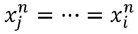


- The properties of

Lemma 2. Note that
Lemma 2 also holds for functions
Fig. 10 illustrates an example of

- Let

- If j = 1 or w πn(i) ≥ w πn(j-1), then fjj is strictly increasing and concave on [0, ∞).
- otherwise when j > 1 and w πn(i) < w πn(j-1),


- Besides,


- As a
first algorithm 1,a pseudocode MaxF is presented which is used to compute the maximum of
P̅ n ] following the result ofLemma 2. MaxF only requires a constant number of basic operations, therefore its complexity is O(1). For ease of reading, some system parameters of a given instance of P, for all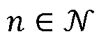


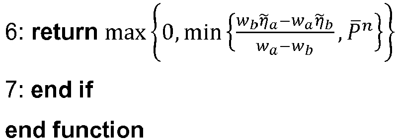
- For solving the above described problem P'scus(n) an Algorithm 2 (SCUS) defined below is used which is based on dynamic programming (DP). Basically, this approach consists in computing recursively the elements of three arrays V, X, T. Let m ∈ {1, ..., M}, j ∈ {1, ..., K} and i ≥ j, V[m,j, i] is defined as the optimal value of the objective function

- A. Constraints C2', C3' and C3",
- B. Variables


- C. Variables with index l > i are equal to zero, i.e.,

- D. There are at most m active users, i.e.,

- X[m,j, i] contains the corresponding optimal value of


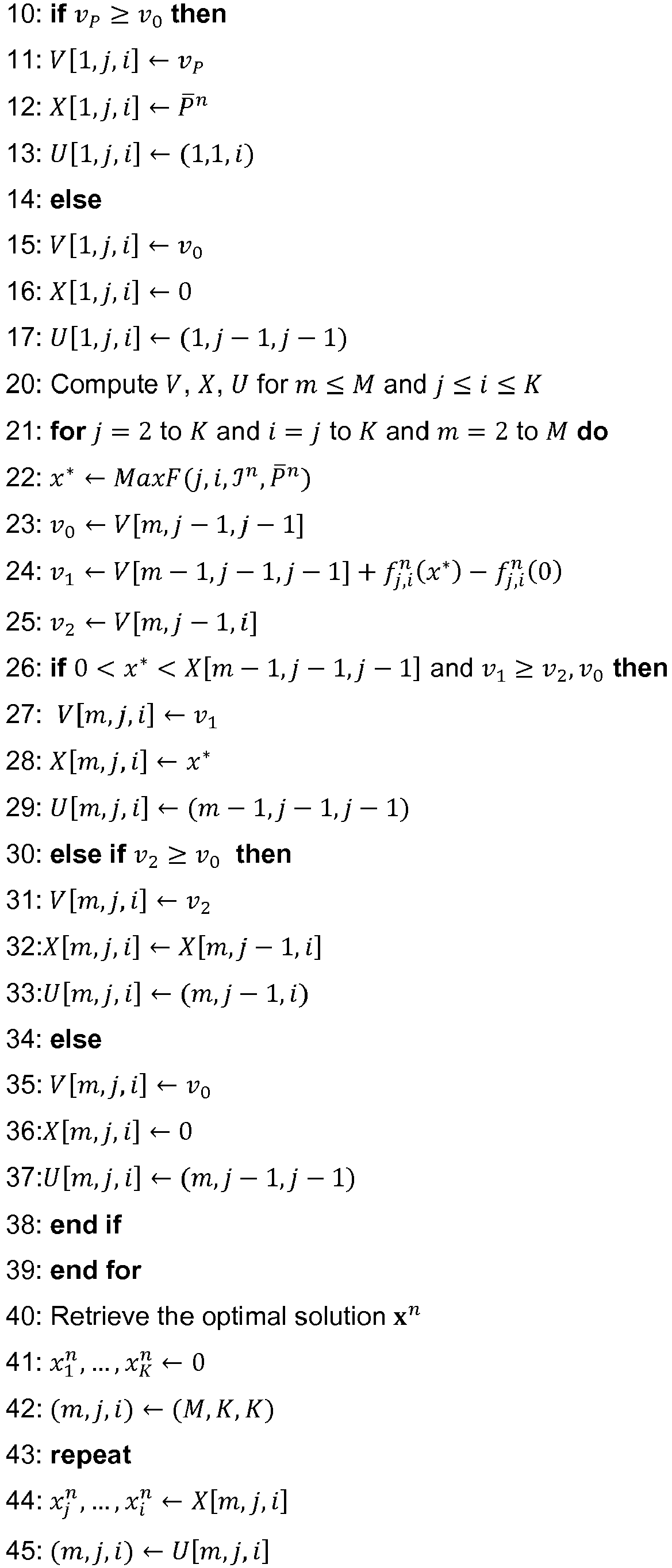

- A line-by-line description and analysis of
Algorithm 2 is given below. -
Lines 1 to 6: The arrays for index (m, j, i) are initialized with j = 1, 1 ≤ i ≤ K and m ∈ {1, ..., M}. It is direct from the above definition that

Lemma 2 that the maximum is obtained for

lines 3 and 4. Atline 5, U[m, 1, i] gets (0,0,0) as there is no previous index. - Lines 7 to 19: The arrays for m = 1 and 2 ≤ j ≤ i ≤ K are initialized. Since


lines 10 to 18. The corresponding allocation is stored in X[m,j, i]. -
Lines 20 to 39: The elements of V, X, U are recursively computed for j = 2 to K, i = j to K, and m = 2 to M. At index (m, j, i), there are three potential cases to consider: - Case v 0 : Suppose that user i is inactive, then


- Case v 1 : Assume that users i and j - 1 are both active. Let x ∗ =


Lemma 2,


- Suppose for the sake of contradiction that x ∗ = 0. It is knowns from
Lemma 2 that


- If (4) and (5) are satisfied, then V[m,j,i] = v 1. v 1 is the sum of the optimal objective with at most m - 1 active users from
indexes 1 to j - 1, i.e., V[m - 1, j - 1, j - 1], and the individual contribution of the active user i, i.e.,
- Case v 2: If i is active and j - 1 is inactive, then


line 25. - The maximum between v 0, v 1 and v 2 is assigned to V[m,j, i], and the corresponding allocation is stored in X[m,j, i]. v 1 is only chosen if, in addition, conditions (4) and (5) are true as shown in line 26.
- Lines 40 to 47: Finally, V[M, K, K] is by definition the optimal value of P. The corresponding optimal allocation x n is retrieved in lines 43 to 46 by finding recursively the indexes (m, j, i) in U used to construct the solution until reaching (0,0,0). At each iteration, X[m,j, i] is assigned to variables

- The optimality and complexity of algorithm SCUS is determined in the following
theorem 3. - Given a subcarrier

P̅ n and M ≥ 1, algorithm SCUS computes the optimal single-carrier power control and user selection of P'scus(n). Its worst case computational complexity is O(MK2). This can be proved as follows. - Regarding the complexity analysis, the computational complexity mainly comes from the computation of V , X and U in
lines 20 to 39. It requires
Algorithm 2 shows that SCUS's construction of V, X, U indeed match their definition. In particular, V[M,K,K] is by definition the optimal value of P'scus(n). The corresponding optimal allocation x n is retrieved in lines 40 to 46. - Next, the MCPC procedure is described.
- In a first example, it is assumed that the multi-carrier power control sub-problem P'MCPC consists in maximizing the WSR taking as input a fixed subcarrier allocation


P̅ n , for


- Fn (
P̅ n ) is the optimal value of the second-stage (single-carroer power control SCPC):
- The first-stage P'MCPC consists in optimizing the allocated power budget
P̅ n among subcarriers

P̅ n . - The second-stage P'SCPC can be solved, for example, by using the following Algorithm 3 (SCPC).

- The idea is to iterate over variables


line 3. If the current allocation satisfies constraint C3', then


line 10. The optimality and complexity of thisalgorithm 3 are presented in the follwing Theorem 4. - Theorem 4: Given subcarrier

P n, algorithm SCPC computes the optimal single-carrier power control. Its worst case computational complexity is
- This can be proved as follows. Regarding the complexity analysis, at each for loop iteration i, the while loop at line 6 has at most i iterations. Thus, the worst case complexity is proportional to


line 10, the following induction hypotheses are true:
- is maximized by

- H 2(i): Constraint C3' is satisfied, i.e.,

- H 3(i): For any l ≤ i, there exists q ≤ l and q' ≥ l such that variables


- This is based on the following: For i = 1, x ∗ computed at
line 3 is indeed the optimal of


Lemma 2, H 3(i) is also satisfied for l = 1 with q = q' = 1. Assume that

- If by assigning


- Otherwise if


- It is known from H 3(i - 1) there exists q ≤ j such that


- As a consequence, the maximum of


- This reasoning is continued until reaching the highest index j ∈ {2, ..., i - 1} such that

P̅ n and
Lemma 2. Properties H 1(i) and H 3(i) remain true by the above construction. Finally, H 2(i) is satisfied at this point. - The convexity of P'MCPC is discussed in the following
Lemma 5. That is, it is shown thatis a convex set and


- This is proved as follows. The convexity ofis direct from its definition in Eqn. (6). It is now proved that each Fn is concave with respect to


Algorithm 3, the only impact ofP̅ n on the allocation is through MaxF thresholding (see lines 4 and 6 in Algorithm 1). Hence, the allocation returned by

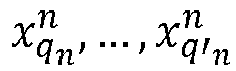


Lemma 2 implies that
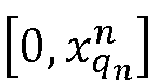


- That is, according to
Lemma 5, . Hence, the optimal multi-carrier power allocation P can be computed efficiently using projected gradient descent. A corresponding MCPC scheme is described in Algorithm 4.


- It is to be noted that in Algorithm 4 the second-stage optimal value Fn (
P̅ n ), defined in P'SCPC, is determined using SCPC as described in the auxiliary function inlines 12 to 13 of Algorithm 4. The search direction at line 4 can be found either using numerical methods or an exact gradient formula (see also the proof of Lemma 5). Note that the step size α atline 5 can be tuned by backtracking line search or exact line search, for example. The latter is adopted to perform simulations, as discussed below. The projection ofP + αΔ on the simplexat line 6 can be computed efficiently, the details of its implementation are omitted here.
- The optimality and complexity of algorithm MCPC are discussed in the following Theorem 6.
- Theorem 6: Given a subcarrier allocation such that


- This is proved as follows. From
Lemma 5 and classical convex programming results, it is clear that projected gradient descent converges to the optimal multi-carrier power control (MCPC) in O(log(1/ε)) iterations. Each iteration requires to compute . Thus, it is dereived from Theorem 4 and

-
Fig. 2 gives an overview of an example for the nested optimization that is designed to solve P'MCPC, wherein the above describedAlgorithms 3 and 4 are employed. It is to be noted that the example ofFig. 2 represents a case where the subcarrier allocation is given as a parameter. - As shown in
Fig. 2 , in S200, input for the algorithms is the subcarrier allocation


P n is applied in order to maximize the WSR
- The output of the first stage algorithm representing an iteration for all subcarriers


P̅ n is input into the second-stage algorithm SCPC. Here, in S220, the optimal single-carrier power allocation xn under power budgetP̅ n is computed. - The output of the second-stage algorithm SCPC, i.e. Fn (
P̅ n ) and xn , are returned to the first-stage algorithm MCPC. Here computation of the received input is effected leading to an output of the optimal power xn for the respective subcarrier which is provided in S230. It is to be noted that the first-stage algorithm MCPC can use the result achieved by processing (computing) the input of the second-stage algorithm SCPC for the next iteration (i.e. first-stage algorithm MCPC and second-stage algorithm SCPC form a loop), e.g. in case the condition in line 7 of algorithm 4 is not fulfilled. - Next, a further example of embodiments is described which is related to the multi-carrier joint subscriber and power allocation (JSPA) procedure indicated above.
- As described above, JSPA represents efficient heuristic joint subcarrier and power allocation scheme which combines MCPC and SCUS. That is, basically, JSPA is similar to the two-stage MCPC approach depicted in
Fig. 2 . However, there are some differences which will be discussed in the following. - One difference is that subcarrier allocation is no longer provided as input. Instead, it has to be optimized in the second-stage. To this end, the second-stage SCPC algorithm (i.e.
algorithm 3 used in the example ofFig. 2 ) is replaced by the optimal single-carrier user selection algorithm SCUS according toalgorithm 2 discussed above. Due to this, the MCPC algorithm, which is described above as Algorithm 4, is to be modified into Algorithm 4' as described below.
-
Fig. 3 gives an overview of an example for the JSPA procedure, wherein the above describedAlgorithms 2 and 4' are employed. It is to be noted that the example ofFig. 3 represents a case where the subcarrier allocation is not given as a parameter. - As shown in
Fig. 3 , in S300, input for the algorithms is the number of multiplexed users per subcarrier M, the maximum power budget
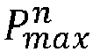
P̅ n is applied in order to maximize the WSR
- The output of the first-stage algorithm representing an iteration for all subcarriers
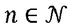
P̅ n is input into the second-stage algorithm SCUS. Here, in S320, the optimal single-carrier power allocation xn under power budgetP̅ n is computed under the constraint
- The output of the second-stage algorithm SCUS, i.e. Fn (
P̅ n ) and xn , are returned to the first-stage algorithm MCPC. Here, computation of the received input is effected leading to an output of the optimal power xn for the respective subcarrier which is provided in S330. It is to be noted that the first-stage algorithm MCPC can use the result achieved by processing (computing) the input of the second-stage algorithm SCUS for the next iteration (i.e. first-stage algorithm MCPC and second-stage algorithm SCUS form a loop), e.g. in case the condition in line 7 of algorithm 4' is not fulfilled. - It is to be noted that although SCUS is optimal, the returned Fn (
P̅ n ) is no longer concave. As a consequence, JSPA is not guaranteed to converge to a global maximum. Each iteration of JSPA requires to compute

Theorem 3, it is derived that each iteration's worst case complexity is O(NMK 2). Nevertheless, as shown in the following by numerical results, it achieves near-optimal weighted sum-rate performance with low complexity. - In the following, numerical results of a comparison between a procedure based on principles of examples of embodiments, as described above, and a procedure based on known methods, such as LDDP and FTPC, are discussed. That is, evaluation results of the WSR, user fairness performance and computational complexity of the provposed JSPA procedure are obtained through numerical simulations, wherein these simulation results are then compared with the near-optimal high complexity benchmark scheme LDDP and FTPC with greedy subcarrier allocation.
- As simulation parameters, the following settings are considered. A cell (e.g. corresponding to
cell 21 ofFig. 1 ) of diameter 500 meters, with one BS (i.e. BS 20) located at its center and K users (e.g.UEs Table 1: Simulation parameters Parameters Value Cell radius 250 m Minimum distance from user to BS 35 m Carrier frequency 2 GHz Path loss model 128.1 + 37.6log10 d dB, d is in km Shadowing Log-normal, 8 dB standard deviation Fading Rayleigh fading with variance 1Noise power spectral density -174 dBm/Hz System bandwidth W 5 MHz Number of subcarriers N 10 Number of users K 5 to 30 Total power budget Pmax 1 W Error tolerance ε 10-4 Parameter M 1 (OMA), 2 and 3 (NOMA) -
Figs. 4 and5 illustrate diagrams showing a comparison of results achievable by implementing the JSPA procedure as depicted, for example, inFig. 3 according to some examples of embodiments and results achievable by using the LDDP procedure. Specifically, inFig. 4 , the WSR of JSPA and LDDP for different systems, i.e., OMA with M = 1, NOMA with M = 2 and M = 3 is shown in relation to the number of users K, while inFig. 5 , the complexity of JSPA and LDDP for different systems, i.e., OMA with M = 1, NOMA with M = 2 and M = 3 is shown by means of the numnber of basic operations in relation to the number of users K. It is to be noted that weights w are generated uniformly at random in [0,1]. - It is to be noted that the LDDP procedure requires to discretize the total power budget Pmax into J power levels. In the simulation forming the basis of
Figs. 4 and5 , J = 100 is chosen. Due to the high computational complexity of LDDP, simulation is conducted only for K = 5 to 20. - As can be seen in
Fig. 4 , the performance loss of JSPA compared to LDDP is less than 0.8% for any number of users K. This indicates that JSPA also achieves near-optimal WSR, close to that of LDDP. In addition, the performance gain of NOMA systems compared to OMA is 7% for M = 2 and 10% for M = 3. - In
Fig. 5 , the number of basic operations (additions, multiplications, comparisons) performed by each scheme is counted, which reflects their computational complexity. As expected from Theorem 4, the complexity of JSPA increases linearly with M (there is a constant difference between the curves of JSPA with M = 1, 2 and 3 in the semi-log plot). JSPA has low complexity, it runs within seconds on a common computer for K ≤ 30, whereas LDDP requires 1600 times more operations for K = 20 and M = 2. -
Figs. 6 and7 illustrate diagrams showing a comparison of results achievable by implementing the JSPA procedure as depicted, for example, inFig. 3 according to some examples of embodiments and results achievable by using the FTPC procedure FTPC with greedy subcarrier allocation (the decay factor of FTPC is set to 0.4, which is a commonly set value). Specifically, inFig. 6 , a proportional fairness index of JSPA and FTPC for different systems, i.e., OMA with M = 1, NOMA with M = 2 and M = 3 is shown in relation to the number of users K, while inFig. 7 , the sum-rate in [bit/s] of JSPA and LDDP for different systems, i.e., OMA with M = 1, NOMA with M = 2 and M = 3 is shown in relation to the number of users K. Specifically,Fig. 6 shows a proportional fairness index defined as
Fig. 7 shows the sum-rate
- It is to be noted that the results shown in
Figs. 6 and7 are achieved by implementing a proportional fair scheduler on one frame, which is composed of T = 20 time slots. The objective of this setup is to evaluate the fairness performance of the JSPA scheme when the weights are chosen according to a proportional fair scheduling. The channel state information is collected at the beginning of the frame. Let Rk (t) be user k's data rate at time slot t ∈ {1, ..., T}, andR̅ k (t) be user k's average data rate prior to t. In a proportional fair scheduling,R̅ k (t) is updated as follows:
- The weight of user k at time t is then set as wk (t) = 1/
R̅ k (t), in order to achieve a good tradeoff between spectral efficiency and user fairness. At the end of the frame, each user k's data rate is averaged over the entire frame, i.e.,
- As can be seen in
Figs. 6 and7 , the JSPA procedure according to examples of embodiments outperforms the heuristic FTPC in both user fairness and sum-rate performance, and in both the OMA and NOMA systems. For example, inFig. 7 for K = 30, the sum-rate gain of JSPA in NOMA with M = 2 and in OMA are respectively 23% and 21%. - As discussed above, according to examples of embodiments of the invetion, the WSR maximization problem in MC-NOMA with cellular power constraint is solved by providing a two-stage approach in which two sub-problems are solved optimally with low complexity. Specifically, the user selection combinatorial problem is solved e.g. by SCUS (as proposed in
Algorithm 2 discussed above, for example) on the basis of dynamic programming. The multi-carrier power control non-convex problem is solved by the two-stage algorithm MCPC (as proposed in Algorithm 4 or 4' discussed above, for example), which uses separability property and gradient descent methods. These algorithms are basic building blocks that can be applied in a wide range of resource allocation problems. Furthermore, JSPA is proposed to tackle the joint subcarrier and power allocation problem. By means of these approaches, near-optimal WSR and user fairness can be achieved. -
Fig. 8 shows a flow chart of a processing executed by a communication network control element or function according to some examples of embodiments, which conducts a radio resource management control for a communication to at least one communication element or function (UE) in a communication network by using a plurality of subcarriers. Preferably, the communication network control element or function is configured to use NOMA for communicating with at least one communication element or function. - In S800, input parameters for the processing are acquired. According to examples of embodiments, as the input parameters, a set of a maximum total power budget, a maximum power budget for each subcarrier, and at least one of a maximum number of multiplexed users per subcarrier and a number of allocated users per subcarrier is acquired.
- In S810, the input parameters are processed by using a first-stage procedure for maximizing a weighted sum-rate for a fixed subcarrier allocation for all subcarriers, and a second-stage procedure for determining a power allocation for a single subcarrier under consideration of specified multiplexing and interference cancellation constraints. A processing result output from the first-stage procedure is input into the second-stage procedure, and a processing result output from the second-stage procedure is returned to the first-stage procedure.
- According to examples of embodiments, in the first-stage procedure, as the input parameters, the maximum total power budget, the maximum power budget for each subcarrier, and the maximum number of multiplexed users per subcarrier is processed by using a projected gradient descent on each power budget for each subcarrier to maximize the weighted sum-rate. The first-stage procedure is based, for example, on the MCPC procedure described above, wherein e.g. one of Algorithm 4' can be employed. From the first-stage procedure to the second stage procedure, an indication of the subcarrier to be considered, the maximum number of multiplexed users per subcarrier and the power budget for the indicated subcarrier are output. Then, in the second-stage procedure, the indication of the subcarrier to be considered, the maximum number of multiplexed users per subcarrier and the power budget for the indicated subcarrier for computing an optimal single-carrier power allocation under the power budget for the indicated subcarrier are processed. Furthermore, in the second-stage procedure, a constraint indicating that the number of allocated users is equal to or less than the maximum number of multiplexed users per subcarrier is considered. The second-stage procedure is based, for example, on the SCUS procedure described above, wherein
e.g. Algorithm 2 can be employed. Then, from the second-stage procedure to the first-stage procedure, an indication of the subcarrier to be considered, a parameter for determining the weighted sum-rate and the computed optimal single-carrier power allocation are output. These parameters are processed in the first-stage procedure. - According to examples of embodiments, in the processing in the first-stage procedure of the parameter for determining the weighted sum-rate and the computed optimal single-carrier power allocation, the computed optimal single-carrier power allocation is output, and/or the parameter for determining the weighted sum-rate and the computed optimal single-carrier power allocation are used in a next iteration for providing an input into the second-stage procedure by updating parameters used in the processing of the first-stage procedure.
- According to examples of embodiments, the processing in the first-stage procedure and the second stage procedure is based on


- In S820, on the basis of results of the processing in the first-stage procedure and the second-stage procedure, a power setting for at least one subcarrier is output.
-
Fig. 9 shows a diagram of a network element or function representing a communication network control element or function according to some examples of embodiments, e.g. theBS 20 ofFig. 1 , which is configured to conduct a radio resource management control procedure as described in connection with some of the examples of embodiments. It is to be noted that the communication network control element or function, like theBS 20 ofFig. 1 , may include further elements or functions besides those described herein below. Furthermore, even though reference is made to a communication network control element or function, the element or function may be also another device or function having a similar task, such as a chipset, a chip, a module, an application etc., which can also be part of a network element or attached as a separate element to a network element, or the like. It should be understood that each block and any combination thereof may be implemented by various means or their combinations, such as hardware, software, firmware, one or more processors and/or circuitry. - The communication network control element or function shown in
Fig. 9 may include a processing circuitry, a processing function, a control unit or aprocessor 201, such as a CPU or the like, which is suitable for executing instructions given by programs or the like related to the paging control procedure. Theprocessor 201 may include one or more processing portions or functions dedicated to specific processing as described below, or the processing may be run in a single processor or processing function. Portions for executing such specific processing may be also provided as discrete elements or within one or more further processors, processing functions or processing portions, such as in one physical processor like a CPU or in one or more physical or virtual entities, for example.Reference sign processing function 201. The I/O units 202 may be used for communicating with a communication element or function like theUEs Fig. 1 , for example. The I/O units 203 may be used for communicating with other network element, like core network elements. The I/O units Reference sign 204 denotes a memory usable, for example, for storing data and programs to be executed by the processor orprocessing function 201 and/or as a working storage of the processor orprocessing function 201. It is to be noted that thememory 204 may be implemented by using one or more memory portions of the same or different type of memory. - The processor or
processing function 201 is configured to execute processing related to the above described paging control processing. In particular, the processor or processing circuitry or function 201 includes one or more of the following sub-portions.Sub-portion 2011 is a processing portion which is usable as a portion for acquiring input data. Theportion 2011 may be configured to perform processing according to S800 ofFig. 8 . Furthermore, the processor or processing circuitry or function 201 may include a sub-portion 2012 usable as a portion for conducting a processing using the first-stage and second-stage procedures. Theportion 2012 may be configured to perform a processing according to S810 ofFig. 8 . In addition, the processor or processing circuitry or function 201 may include a sub-portion 2013 usable as a portion for outputting the power setting value. Theportion 2013 may be configured to perform a processing according to S820 ofFig. 8 . - It is to be noted that examples of embodiments of the invention are applicable to various different network configurations. In other words, the examples shown in the above described figures, which are used as a basis for the above discussed examples, are only illustrative and do not limit the present invention in any way. That is, additional further existing and proposed new functionalities available in a corresponding operating environment may be used in connection with examples of embodiments of the invention based on the principles defined.
- According to a further example of embodiments, there is provided, for example, an apparatus for use by a communication network control element or function configured to conduct a radio resource management control for a communication to at least one communication element or function in a communication network by using a plurality of subcarriers, the apparatus comprising: means configured to acquire input parameters; means configured to process the input parameters by using a first-stage procedure for maximizing a weighted sum-rate for a fixed subcarrier allocation for all subcarriers, and a second-stage procedure for determining a power allocation for a single subcarrier under consideration of specified multiplexing and interference cancellation constraints, wherein a processing result output from the first-stage procedure is input into the second-stage procedure, and a processing result output from the second-stage procedure is returned to the first-stage procedure; and means configured to output, on the basis of results of the processing in the first-stage procedure and the second-stage procedure, a power setting for at least one subcarrier.
- Furthermore, according to some other examples of embodiments, the above defined apparatus may further comprise means for conducting at least one of the processing defined in the above described methods, for example a method according to that described in connection with
Fig 8 . - According to a further example of embodiments, there is provided, for example, a non-transitory computer readable medium comprising program instructions for causing an apparatus to perform at least the following: conducting a radio resource management control for a communication to at least one communication element or function in a communication network by using a plurality of subcarriers; acquiring input parameters; processing the input parameters by using a first-stage procedure for maximizing a weighted sum-rate for a fixed subcarrier allocation for all subcarriers, and a second-stage procedure for determining a power allocation for a single subcarrier under consideration of specified multiplexing and interference cancellation constraints, wherein a processing result output from the first-stage procedure is input into the second-stage procedure, and a processing result output from the second-stage procedure is returned to the first-stage procedure; and outputting, on the basis of results of the processing in the first-stage procedure and the second-stage procedure, a power setting for at least one subcarrier.
- It should be appreciated that
- an access technology via which traffic is transferred to and from an entity in the communication network may be any suitable present or future technology, such as WLAN (Wireless Local Access Network), WiMAX (Worldwide Interoperability for Microwave Access), LTE, LTE-A, 5G, Bluetooth, Infrared, and the like may be used; additionally, embodiments may also apply wired technologies, e.g. IP based access technologies like cable networks or fixed lines.
- embodiments suitable to be implemented as software code or portions of it and being run using a processor or processing function are software code independent and can be specified using any known or future developed programming language, such as a high-level programming language, such as objective-C, C, C++, C#, Java, Python, Javascript, other scripting languages etc., or a low-level programming language, such as a machine language, or an assembler.
- implementation of embodiments is hardware independent and may be implemented using any known or future developed hardware technology or any hybrids of these, such as a microprocessor or CPU (Central Processing Unit), MOS (Metal Oxide Semiconductor), CMOS (Complementary MOS), BiMOS (Bipolar MOS), BiCMOS (Bipolar CMOS), ECL (Emitter Coupled Logic), and/or TTL (Transistor-Transistor Logic).
- embodiments may be implemented as individual devices, apparatuses, units, means or functions, or in a distributed fashion, for example, one or more processors or processing functions may be used or shared in the processing, or one or more processing sections or processing portions may be used and shared in the processing, wherein one physical processor or more than one physical processor may be used for implementing one or more processing portions dedicated to specific processing as described,
- an apparatus may be implemented by a semiconductor chip, a chipset, or a (hardware) module including such chip or chipset;
- embodiments may also be implemented as any combination of hardware and software, such as ASIC (Application Specific IC (Integrated Circuit)) components, FPGA (Field-programmable Gate Arrays) or CPLD (Complex Programmable Logic Device) components or DSP (Digital Signal Processor) components.
- embodiments may also be implemented as computer program products, including a computer usable medium having a computer readable program code embodied therein, the computer readable program code adapted to execute a process as described in embodiments, wherein the computer usable medium may be a non-transitory medium. Although the present invention has been described herein before with reference to particular embodiments thereof, the present invention is not limited thereto and various modifications can be made thereto. The intended limitations are defined by the appended claims.
Claims (10)
- An apparatus for use by a communication network control element or function configured to conduct a radio resource management control for a communication to at least one communication element or function in a communication network by using a plurality of subcarriers, the apparatus comprisingat least one processing circuitry, andat least one memory for storing instructions to be executed by the processing circuitry, wherein the at least one memory and the instructions are configured to, with the at least one processing circuitry, cause the apparatus at least:to acquire input parameters;to process the input parameters by usinga first-stage procedure for maximizing a weighted sum-rate for a fixed subcarrier allocation for all subcarriers, anda second-stage procedure for determining a power allocation for a single subcarrier under consideration of specified multiplexing and interference cancellation constraints,wherein a processing result output from the first-stage procedure is input into the second-stage procedure, and a processing result output from the second-stage procedure is returned to the first-stage procedure;to output, on the basis of results of the processing in the first-stage procedure and the second-stage procedure, a power setting for at least one subcarrierto acquire, as the input parameters, a maximum total power budget, a maximum power budget for each subcarrier, and at least one of a maximum number of multiplexed users per subcarrier and a number of allocated users per subcarrier;characterized in that the at least one memory and the instructions are configured to, with the at least one processing circuitry, cause the apparatus at least:to process, in the first-stage procedure, as the input parameters, the maximum total power budget, the maximum power budget for each subcarrier, and the maximum number of multiplexed users per subcarrier, by using a projected gradient descent on each power budget for each subcarrier to maximize the weighted sum-rate,to output, from the first-stage procedure to the second stage procedure, an indication of the subcarrier to be considered, the maximum number of multiplexed users per subcarrier and the power budget for the indicated subcarrier,to process, in the second-stage procedure, the indication of the subcarrier to be considered, the maximum number of multiplexed users per subcarrier and the power budget for the indicated subcarrier for computing an optimal single-carrier power allocation under the power budget for the indicated subcarrier and by considering a constraint indicating that the number of allocated users is equal to or less than the maximum number of multiplexed users per subcarrier,to output, from the second-stage procedure to the first-stage procedure, an indication of the subcarrier to be considered, a parameter for determining the weighted sum-rate and the computed optimal single-carrier power allocation, andto process, in the first-stage procedure, the parameter for determining the weighted sum-rate and the computed optimal single-carrier power allocation.
- The apparatus according to claim 1, wherein the at least one memory and the instructions are further configured to, with the at least one processing circuitry, cause the apparatus at least:In the processing in the first-stage procedure of the parameter for determining the weighted sum-rate and the computed optimal single-carrier power allocation, to conduct at least one ofoutputting the computed optimal single-carrier power allocation, andusing the parameter for determining the weighted sum-rate and the computed optimal single-carrier power allocation in a next iteration for providing an input into the second-stage procedure by updating parameters used in the processing of the first-stage procedure.
- The apparatus according to claim 1 or 2, wherein the processing in the first-stage procedure and the second stage procedure is based on


- The apparatus according to any of claims 1 to 3, wherein the communication network control element or function is configured to use at least one of non-orthogonal muliple access and orthogonal multiple access for communicating with the at least one communication element or function.
- A method for use in a communication network control element or function configured to conduct a radio resource management control for a communication to at least one communication element or function in a communication network by using a plurality of subcarriers, the method comprisingacquiring input parameters;processing the input parameters by usinga first-stage procedure for maximizing a weighted sum-rate for a fixed subcarrier allocation for all subcarriers, anda second-stage procedure for determining a power allocation for a single subcarrier under consideration of specified multiplexing and interference cancellation constraints,wherein a processing result output from the first-stage procedure is input into the second-stage procedure, and a processing result output from the second-stage procedure is returned to the first-stage procedure;outputting, on the basis of results of the processing in the first-stage procedure and the second-stage procedure, a power setting for at least one subcarrier;acquiring, as the input parameters, a maximum total power budget, a maximum power budget for each subcarrier, and at least one of a maximum number of multiplexed users per subcarrier and a number of allocated users per subcarrier;characterized in that the method further comprises:processing, in the first-stage procedure, as the input parameters, the maximum total power budget, the maximum power budget for each subcarrier, and the maximum number of multiplexed users per subcarrier, by using a projected gradient descent on each power budget for each subcarrier to maximize the weighted sum-rate,outputting, from the first-stage procedure to the second stage procedure, an indication of the subcarrier to be considered, the maximum number of multiplexed users per subcarrier and the power budget for the indicated subcarrier,processing, in the second-stage procedure, the indication of the subcarrier to be considered, the maximum number of multiplexed users per subcarrier and the power budget for the indicated subcarrier for computing an optimal single-carrier power allocation under the power budget for the indicated subcarrier and by considering a constraint indicating that the number of allocated users is equal to or less than the maximum number of multiplexed users per subcarrier,outputting, from the second-stage procedure to the first-stage procedure, an indication of the subcarrier to be considered, a parameter for determining the weighted sum-rate and the computed optimal single-carrier power allocation, andprocessing, in the first-stage procedure, the parameter for determining the weighted sum-rate and the computed optimal single-carrier power allocation.
- The method according to claim 5, further comprisingconducting, In the processing in the first-stage procedure of the parameter for determining the weighted sum-rate and the computed optimal single-carrier power allocation, at least one ofoutputting the computed optimal single-carrier power allocation, andusing the parameter for determining the weighted sum-rate and the computed optimal single-carrier power allocation in a next iteration for providing an input into the second-stage procedure by updating parameters used in the processing of the first-stage procedure.
- The method according to claim 5 or 6, wherein the processing in the first-stage procedure and the second stage procedure is based on


- The method according to any of claims 5 to 7, wherein the communication network control element or function is configured to use at least one of non-orthogonal muliple access and orthogonal multiple access for communicating with the at least one communication element or function.
- A computer program product for a computer, including software code portions for performing the steps of any of claims 5 to 8 when said product is run on the computer.
- The computer program product according to claim 9, whereinthe computer program product includes a computer-readable medium on which said software code portions are stored, and/orthe computer program product is directly loadable into the internal memory of the computer and/or transmittable via a network by means of at least one of upload, download and push procedures.
Applications Claiming Priority (1)
| Application Number | Priority Date | Filing Date | Title |
|---|---|---|---|
| PCT/EP2018/081779 WO2020104008A1 (en) | 2018-11-19 | 2018-11-19 | Method and apparatus for maximizing weighted sum rate |
Publications (2)
| Publication Number | Publication Date |
|---|---|
| EP3884715A1 EP3884715A1 (en) | 2021-09-29 |
| EP3884715B1 true EP3884715B1 (en) | 2023-02-22 |
Family
ID=64362563
Family Applications (1)
| Application Number | Title | Priority Date | Filing Date |
|---|---|---|---|
| EP18804620.5A Active EP3884715B1 (en) | 2018-11-19 | 2018-11-19 | Method and apparatus for maximizing weighted sum rate |
Country Status (4)
| Country | Link |
|---|---|
| US (1) | US11582703B2 (en) |
| EP (1) | EP3884715B1 (en) |
| CN (1) | CN113228756B (en) |
| WO (1) | WO2020104008A1 (en) |
Families Citing this family (3)
| Publication number | Priority date | Publication date | Assignee | Title |
|---|---|---|---|---|
| US11863359B1 (en) * | 2021-05-11 | 2024-01-02 | Amazon Technologies, Inc. | Subcarrier pre-equalization technology for frequency selective fading characteristics of wireless channels |
| CN114615745B (en) * | 2022-03-10 | 2023-08-08 | 中国电子科技集团公司第十研究所 | A method for joint scheduling of channel access and transmission power in wireless ad hoc networks |
| CN115134831B (en) * | 2022-06-28 | 2024-10-22 | 南京工程学院 | Method for designing user fairness index of downlink NOMA system based on rate variance |
Family Cites Families (8)
| Publication number | Priority date | Publication date | Assignee | Title |
|---|---|---|---|---|
| US7245879B2 (en) * | 2003-08-08 | 2007-07-17 | Intel Corporation | Apparatus and associated methods to perform intelligent transmit power control with subcarrier puncturing |
| US8174959B2 (en) * | 2008-03-11 | 2012-05-08 | Nec Laboratories America, Inc. | Auction based resource allocation in wireless systems |
| CN103491634B (en) * | 2013-09-13 | 2016-06-22 | 宁波大学 | Based on the resource allocation methods of minimum power in multi-user cooperative relay system |
| CN104702396B (en) * | 2015-04-07 | 2018-01-09 | 山东大学 | Cooperation based on effectiveness relays the federated resource distribution method of cognitive system more |
| JPWO2017135302A1 (en) * | 2016-02-04 | 2018-11-29 | 株式会社Nttドコモ | Base station, user apparatus, precoding matrix application method, and precoding matrix acquisition method |
| CN106851835B (en) * | 2017-01-06 | 2019-10-15 | 北京邮电大学 | A resource allocation method and device |
| CN106851726A (en) * | 2017-01-19 | 2017-06-13 | 西安电子科技大学 | A kind of cross-layer resource allocation method based on minimum speed limit constraint |
| US12082201B2 (en) * | 2019-06-11 | 2024-09-03 | Comcast Cable Communications, Llc | Wireless communications and control information transmission/reception |
-
2018
- 2018-11-19 EP EP18804620.5A patent/EP3884715B1/en active Active
- 2018-11-19 CN CN201880100408.2A patent/CN113228756B/en active Active
- 2018-11-19 WO PCT/EP2018/081779 patent/WO2020104008A1/en not_active Ceased
- 2018-11-19 US US17/292,858 patent/US11582703B2/en active Active
Also Published As
| Publication number | Publication date |
|---|---|
| WO2020104008A1 (en) | 2020-05-28 |
| CN113228756A (en) | 2021-08-06 |
| US20210410082A1 (en) | 2021-12-30 |
| EP3884715A1 (en) | 2021-09-29 |
| CN113228756B (en) | 2024-06-07 |
| US11582703B2 (en) | 2023-02-14 |
Similar Documents
| Publication | Publication Date | Title |
|---|---|---|
| US11581989B2 (en) | System and method for OFDMA tone allocation in next generation Wi-Fi networks | |
| Ghimire et al. | Resource allocation, transmission coordination and user association in heterogeneous networks: A flow-based unified approach | |
| Hoang et al. | Resource allocation for D2D communication underlaid cellular networks using graph-based approach | |
| US20240389085A1 (en) | Spectral shaping for wireless communications | |
| EP2734006B1 (en) | Resource allocation for minimum satisfaction guarantees in multi-service and multi-antenna networks | |
| US10880906B2 (en) | Apparatuses, methods and computer programs for implementing fairness and complexity-constrained a non-orthogonal multiple access (NOMA) scheme | |
| US20230309123A1 (en) | Method and apparatus for sl positioning reference signals | |
| US11582703B2 (en) | Method and apparatus for maximizing weighted sum rate | |
| CN109391355A (en) | Method, chip and system for wireless communication | |
| CN120641783A (en) | Systems, methods, and apparatus for model validation of AI-based user equipment (UE) positioning | |
| US12035144B2 (en) | Spectrum management device, electronic device, radio communication method, and storage medium | |
| CN119404462A (en) | Signalling mode for time drift reference signal | |
| CN115606135A (en) | Determine default beam and QCL conflict handling | |
| CN119422415A (en) | Signaling the power offset between reference and data tones | |
| CN117014114A (en) | A bypass-based positioning method and device | |
| Um et al. | Implementation of platform for long‐term evolution cell perspective resource utilization analysis | |
| US20240283295A1 (en) | Techniques for load resistance signaling for wireless power transfer | |
| Alinejad et al. | Dynamic subframe allocation for mobile broadband m-health using IEEE 802.16 j mobile multihop relay networks | |
| Soleymani et al. | Dedicated sub-granting radio resource in overlay d2d communication | |
| CN119547375A (en) | Hybrid Waveform Communications | |
| Daghal et al. | LTE network performance evaluation based on effects of various parameters on the cell range and MAPL | |
| US20250358089A1 (en) | Flexible duplex signaling for indicating duplex support | |
| KR101626952B1 (en) | Method of improving service rate using minimum received power in cognitive relay network and apparatus thereof | |
| Hajiaghayi et al. | Jointly optimal bit loading, channel pairing and power allocation for multi-channel relaying | |
| US12634753B2 (en) | Transport block size determination in subband full duplex slots |
Legal Events
| Date | Code | Title | Description |
|---|---|---|---|
| STAA | Information on the status of an ep patent application or granted ep patent |
Free format text: STATUS: UNKNOWN |
|
| STAA | Information on the status of an ep patent application or granted ep patent |
Free format text: STATUS: THE INTERNATIONAL PUBLICATION HAS BEEN MADE |
|
| PUAI | Public reference made under article 153(3) epc to a published international application that has entered the european phase |
Free format text: ORIGINAL CODE: 0009012 |
|
| STAA | Information on the status of an ep patent application or granted ep patent |
Free format text: STATUS: REQUEST FOR EXAMINATION WAS MADE |
|
| 17P | Request for examination filed |
Effective date: 20210621 |
|
| AK | Designated contracting states |
Kind code of ref document: A1 Designated state(s): AL AT BE BG CH CY CZ DE DK EE ES FI FR GB GR HR HU IE IS IT LI LT LU LV MC MK MT NL NO PL PT RO RS SE SI SK SM TR |
|
| DAV | Request for validation of the european patent (deleted) | ||
| DAX | Request for extension of the european patent (deleted) | ||
| REG | Reference to a national code |
Ref country code: DE Ref legal event code: R079 Ref document number: 602018046463 Country of ref document: DE Free format text: PREVIOUS MAIN CLASS: H04W0052240000 Ipc: H04L0005040000 |
|
| GRAP | Despatch of communication of intention to grant a patent |
Free format text: ORIGINAL CODE: EPIDOSNIGR1 |
|
| STAA | Information on the status of an ep patent application or granted ep patent |
Free format text: STATUS: GRANT OF PATENT IS INTENDED |
|
| RIC1 | Information provided on ipc code assigned before grant |
Ipc: H04W 52/36 20090101ALI20221107BHEP Ipc: H04W 52/34 20090101ALI20221107BHEP Ipc: H04W 52/26 20090101ALI20221107BHEP Ipc: H04W 52/24 20090101ALI20221107BHEP Ipc: H04W 52/14 20090101ALI20221107BHEP Ipc: H04L 5/00 20060101ALI20221107BHEP Ipc: H04L 5/04 20060101AFI20221107BHEP |
|
| INTG | Intention to grant announced |
Effective date: 20221128 |
|
| GRAS | Grant fee paid |
Free format text: ORIGINAL CODE: EPIDOSNIGR3 |
|
| GRAA | (expected) grant |
Free format text: ORIGINAL CODE: 0009210 |
|
| STAA | Information on the status of an ep patent application or granted ep patent |
Free format text: STATUS: THE PATENT HAS BEEN GRANTED |
|
| AK | Designated contracting states |
Kind code of ref document: B1 Designated state(s): AL AT BE BG CH CY CZ DE DK EE ES FI FR GB GR HR HU IE IS IT LI LT LU LV MC MK MT NL NO PL PT RO RS SE SI SK SM TR |
|
| REG | Reference to a national code |
Ref country code: GB Ref legal event code: FG4D |
|
| REG | Reference to a national code |
Ref country code: CH Ref legal event code: EP |
|
| REG | Reference to a national code |
Ref country code: AT Ref legal event code: REF Ref document number: 1550203 Country of ref document: AT Kind code of ref document: T Effective date: 20230315 Ref country code: IE Ref legal event code: FG4D |
|
| REG | Reference to a national code |
Ref country code: DE Ref legal event code: R096 Ref document number: 602018046463 Country of ref document: DE |
|
| REG | Reference to a national code |
Ref country code: LT Ref legal event code: MG9D |
|
| REG | Reference to a national code |
Ref country code: NL Ref legal event code: MP Effective date: 20230222 |
|
| P01 | Opt-out of the competence of the unified patent court (upc) registered |
Effective date: 20230527 |
|
| REG | Reference to a national code |
Ref country code: AT Ref legal event code: MK05 Ref document number: 1550203 Country of ref document: AT Kind code of ref document: T Effective date: 20230222 |
|
| PG25 | Lapsed in a contracting state [announced via postgrant information from national office to epo] |
Ref country code: RS Free format text: LAPSE BECAUSE OF FAILURE TO SUBMIT A TRANSLATION OF THE DESCRIPTION OR TO PAY THE FEE WITHIN THE PRESCRIBED TIME-LIMIT Effective date: 20230222 Ref country code: PT Free format text: LAPSE BECAUSE OF FAILURE TO SUBMIT A TRANSLATION OF THE DESCRIPTION OR TO PAY THE FEE WITHIN THE PRESCRIBED TIME-LIMIT Effective date: 20230622 Ref country code: NO Free format text: LAPSE BECAUSE OF FAILURE TO SUBMIT A TRANSLATION OF THE DESCRIPTION OR TO PAY THE FEE WITHIN THE PRESCRIBED TIME-LIMIT Effective date: 20230522 Ref country code: NL Free format text: LAPSE BECAUSE OF FAILURE TO SUBMIT A TRANSLATION OF THE DESCRIPTION OR TO PAY THE FEE WITHIN THE PRESCRIBED TIME-LIMIT Effective date: 20230222 Ref country code: LV Free format text: LAPSE BECAUSE OF FAILURE TO SUBMIT A TRANSLATION OF THE DESCRIPTION OR TO PAY THE FEE WITHIN THE PRESCRIBED TIME-LIMIT Effective date: 20230222 Ref country code: LT Free format text: LAPSE BECAUSE OF FAILURE TO SUBMIT A TRANSLATION OF THE DESCRIPTION OR TO PAY THE FEE WITHIN THE PRESCRIBED TIME-LIMIT Effective date: 20230222 Ref country code: HR Free format text: LAPSE BECAUSE OF FAILURE TO SUBMIT A TRANSLATION OF THE DESCRIPTION OR TO PAY THE FEE WITHIN THE PRESCRIBED TIME-LIMIT Effective date: 20230222 Ref country code: ES Free format text: LAPSE BECAUSE OF FAILURE TO SUBMIT A TRANSLATION OF THE DESCRIPTION OR TO PAY THE FEE WITHIN THE PRESCRIBED TIME-LIMIT Effective date: 20230222 Ref country code: AT Free format text: LAPSE BECAUSE OF FAILURE TO SUBMIT A TRANSLATION OF THE DESCRIPTION OR TO PAY THE FEE WITHIN THE PRESCRIBED TIME-LIMIT Effective date: 20230222 |
|
| PG25 | Lapsed in a contracting state [announced via postgrant information from national office to epo] |
Ref country code: SE Free format text: LAPSE BECAUSE OF FAILURE TO SUBMIT A TRANSLATION OF THE DESCRIPTION OR TO PAY THE FEE WITHIN THE PRESCRIBED TIME-LIMIT Effective date: 20230222 Ref country code: PL Free format text: LAPSE BECAUSE OF FAILURE TO SUBMIT A TRANSLATION OF THE DESCRIPTION OR TO PAY THE FEE WITHIN THE PRESCRIBED TIME-LIMIT Effective date: 20230222 Ref country code: IS Free format text: LAPSE BECAUSE OF FAILURE TO SUBMIT A TRANSLATION OF THE DESCRIPTION OR TO PAY THE FEE WITHIN THE PRESCRIBED TIME-LIMIT Effective date: 20230622 Ref country code: GR Free format text: LAPSE BECAUSE OF FAILURE TO SUBMIT A TRANSLATION OF THE DESCRIPTION OR TO PAY THE FEE WITHIN THE PRESCRIBED TIME-LIMIT Effective date: 20230523 Ref country code: FI Free format text: LAPSE BECAUSE OF FAILURE TO SUBMIT A TRANSLATION OF THE DESCRIPTION OR TO PAY THE FEE WITHIN THE PRESCRIBED TIME-LIMIT Effective date: 20230222 |
|
| PG25 | Lapsed in a contracting state [announced via postgrant information from national office to epo] |
Ref country code: SM Free format text: LAPSE BECAUSE OF FAILURE TO SUBMIT A TRANSLATION OF THE DESCRIPTION OR TO PAY THE FEE WITHIN THE PRESCRIBED TIME-LIMIT Effective date: 20230222 Ref country code: RO Free format text: LAPSE BECAUSE OF FAILURE TO SUBMIT A TRANSLATION OF THE DESCRIPTION OR TO PAY THE FEE WITHIN THE PRESCRIBED TIME-LIMIT Effective date: 20230222 Ref country code: EE Free format text: LAPSE BECAUSE OF FAILURE TO SUBMIT A TRANSLATION OF THE DESCRIPTION OR TO PAY THE FEE WITHIN THE PRESCRIBED TIME-LIMIT Effective date: 20230222 Ref country code: DK Free format text: LAPSE BECAUSE OF FAILURE TO SUBMIT A TRANSLATION OF THE DESCRIPTION OR TO PAY THE FEE WITHIN THE PRESCRIBED TIME-LIMIT Effective date: 20230222 Ref country code: CZ Free format text: LAPSE BECAUSE OF FAILURE TO SUBMIT A TRANSLATION OF THE DESCRIPTION OR TO PAY THE FEE WITHIN THE PRESCRIBED TIME-LIMIT Effective date: 20230222 |
|
| REG | Reference to a national code |
Ref country code: DE Ref legal event code: R097 Ref document number: 602018046463 Country of ref document: DE |
|
| PG25 | Lapsed in a contracting state [announced via postgrant information from national office to epo] |
Ref country code: SK Free format text: LAPSE BECAUSE OF FAILURE TO SUBMIT A TRANSLATION OF THE DESCRIPTION OR TO PAY THE FEE WITHIN THE PRESCRIBED TIME-LIMIT Effective date: 20230222 |
|
| PLBE | No opposition filed within time limit |
Free format text: ORIGINAL CODE: 0009261 |
|
| STAA | Information on the status of an ep patent application or granted ep patent |
Free format text: STATUS: NO OPPOSITION FILED WITHIN TIME LIMIT |
|
| 26N | No opposition filed |
Effective date: 20231123 |
|
| PG25 | Lapsed in a contracting state [announced via postgrant information from national office to epo] |
Ref country code: SI Free format text: LAPSE BECAUSE OF FAILURE TO SUBMIT A TRANSLATION OF THE DESCRIPTION OR TO PAY THE FEE WITHIN THE PRESCRIBED TIME-LIMIT Effective date: 20230222 |
|
| PG25 | Lapsed in a contracting state [announced via postgrant information from national office to epo] |
Ref country code: IT Free format text: LAPSE BECAUSE OF FAILURE TO SUBMIT A TRANSLATION OF THE DESCRIPTION OR TO PAY THE FEE WITHIN THE PRESCRIBED TIME-LIMIT Effective date: 20230222 |
|
| REG | Reference to a national code |
Ref country code: CH Ref legal event code: PL |
|
| PG25 | Lapsed in a contracting state [announced via postgrant information from national office to epo] |
Ref country code: MC Free format text: LAPSE BECAUSE OF FAILURE TO SUBMIT A TRANSLATION OF THE DESCRIPTION OR TO PAY THE FEE WITHIN THE PRESCRIBED TIME-LIMIT Effective date: 20230222 |
|
| PG25 | Lapsed in a contracting state [announced via postgrant information from national office to epo] |
Ref country code: LU Free format text: LAPSE BECAUSE OF NON-PAYMENT OF DUE FEES Effective date: 20231119 |
|
| PG25 | Lapsed in a contracting state [announced via postgrant information from national office to epo] |
Ref country code: CH Free format text: LAPSE BECAUSE OF NON-PAYMENT OF DUE FEES Effective date: 20231130 |
|
| PG25 | Lapsed in a contracting state [announced via postgrant information from national office to epo] |
Ref country code: MC Free format text: LAPSE BECAUSE OF FAILURE TO SUBMIT A TRANSLATION OF THE DESCRIPTION OR TO PAY THE FEE WITHIN THE PRESCRIBED TIME-LIMIT Effective date: 20230222 Ref country code: LU Free format text: LAPSE BECAUSE OF NON-PAYMENT OF DUE FEES Effective date: 20231119 Ref country code: CH Free format text: LAPSE BECAUSE OF NON-PAYMENT OF DUE FEES Effective date: 20231130 |
|
| REG | Reference to a national code |
Ref country code: BE Ref legal event code: MM Effective date: 20231130 |
|
| REG | Reference to a national code |
Ref country code: IE Ref legal event code: MM4A |
|
| PG25 | Lapsed in a contracting state [announced via postgrant information from national office to epo] |
Ref country code: IE Free format text: LAPSE BECAUSE OF NON-PAYMENT OF DUE FEES Effective date: 20231119 |
|
| PG25 | Lapsed in a contracting state [announced via postgrant information from national office to epo] |
Ref country code: BE Free format text: LAPSE BECAUSE OF NON-PAYMENT OF DUE FEES Effective date: 20231130 |
|
| PG25 | Lapsed in a contracting state [announced via postgrant information from national office to epo] |
Ref country code: IE Free format text: LAPSE BECAUSE OF NON-PAYMENT OF DUE FEES Effective date: 20231119 Ref country code: BE Free format text: LAPSE BECAUSE OF NON-PAYMENT OF DUE FEES Effective date: 20231130 |
|
| PG25 | Lapsed in a contracting state [announced via postgrant information from national office to epo] |
Ref country code: BG Free format text: LAPSE BECAUSE OF FAILURE TO SUBMIT A TRANSLATION OF THE DESCRIPTION OR TO PAY THE FEE WITHIN THE PRESCRIBED TIME-LIMIT Effective date: 20230222 |
|
| PG25 | Lapsed in a contracting state [announced via postgrant information from national office to epo] |
Ref country code: BG Free format text: LAPSE BECAUSE OF FAILURE TO SUBMIT A TRANSLATION OF THE DESCRIPTION OR TO PAY THE FEE WITHIN THE PRESCRIBED TIME-LIMIT Effective date: 20230222 |
|
| PG25 | Lapsed in a contracting state [announced via postgrant information from national office to epo] |
Ref country code: CY Free format text: LAPSE BECAUSE OF FAILURE TO SUBMIT A TRANSLATION OF THE DESCRIPTION OR TO PAY THE FEE WITHIN THE PRESCRIBED TIME-LIMIT; INVALID AB INITIO Effective date: 20181119 |
|
| PG25 | Lapsed in a contracting state [announced via postgrant information from national office to epo] |
Ref country code: HU Free format text: LAPSE BECAUSE OF FAILURE TO SUBMIT A TRANSLATION OF THE DESCRIPTION OR TO PAY THE FEE WITHIN THE PRESCRIBED TIME-LIMIT; INVALID AB INITIO Effective date: 20181119 |
|
| PGFP | Annual fee paid to national office [announced via postgrant information from national office to epo] |
Ref country code: FR Payment date: 20250930 Year of fee payment: 8 |
|
| PG25 | Lapsed in a contracting state [announced via postgrant information from national office to epo] |
Ref country code: TR Free format text: LAPSE BECAUSE OF FAILURE TO SUBMIT A TRANSLATION OF THE DESCRIPTION OR TO PAY THE FEE WITHIN THE PRESCRIBED TIME-LIMIT Effective date: 20230222 |
|
| PGFP | Annual fee paid to national office [announced via postgrant information from national office to epo] |
Ref country code: DE Payment date: 20250930 Year of fee payment: 8 |
|
| PGFP | Annual fee paid to national office [announced via postgrant information from national office to epo] |
Ref country code: GB Payment date: 20251001 Year of fee payment: 8 |