EP3884619B1 - N+1 redundancy for virtualized services with low latency fail-over - Google Patents
N+1 redundancy for virtualized services with low latency fail-over Download PDFInfo
- Publication number
- EP3884619B1 EP3884619B1 EP19809923.6A EP19809923A EP3884619B1 EP 3884619 B1 EP3884619 B1 EP 3884619B1 EP 19809923 A EP19809923 A EP 19809923A EP 3884619 B1 EP3884619 B1 EP 3884619B1
- Authority
- EP
- European Patent Office
- Prior art keywords
- node
- standby
- primary
- failed
- address
- Prior art date
- Legal status (The legal status is an assumption and is not a legal conclusion. Google has not performed a legal analysis and makes no representation as to the accuracy of the status listed.)
- Active
Links
Images




Classifications
-
- H—ELECTRICITY
- H04—ELECTRIC COMMUNICATION TECHNIQUE
- H04L—TRANSMISSION OF DIGITAL INFORMATION, e.g. TELEGRAPHIC COMMUNICATION
- H04L41/00—Arrangements for maintenance, administration or management of data switching networks, e.g. of packet switching networks
- H04L41/06—Management of faults, events, alarms or notifications
- H04L41/0654—Management of faults, events, alarms or notifications using network fault recovery
-
- H—ELECTRICITY
- H04—ELECTRIC COMMUNICATION TECHNIQUE
- H04L—TRANSMISSION OF DIGITAL INFORMATION, e.g. TELEGRAPHIC COMMUNICATION
- H04L67/00—Network arrangements or protocols for supporting network services or applications
- H04L67/01—Protocols
- H04L67/10—Protocols in which an application is distributed across nodes in the network
- H04L67/1095—Replication or mirroring of data, e.g. scheduling or transport for data synchronisation between network nodes
-
- H—ELECTRICITY
- H04—ELECTRIC COMMUNICATION TECHNIQUE
- H04L—TRANSMISSION OF DIGITAL INFORMATION, e.g. TELEGRAPHIC COMMUNICATION
- H04L67/00—Network arrangements or protocols for supporting network services or applications
- H04L67/01—Protocols
- H04L67/10—Protocols in which an application is distributed across nodes in the network
- H04L67/1097—Protocols in which an application is distributed across nodes in the network for distributed storage of data in networks, e.g. transport arrangements for network file system [NFS], storage area networks [SAN] or network attached storage [NAS]
-
- H—ELECTRICITY
- H04—ELECTRIC COMMUNICATION TECHNIQUE
- H04L—TRANSMISSION OF DIGITAL INFORMATION, e.g. TELEGRAPHIC COMMUNICATION
- H04L67/00—Network arrangements or protocols for supporting network services or applications
- H04L67/14—Session management
- H04L67/142—Managing session states for stateless protocols; Signalling session states; State transitions; Keeping-state mechanisms
-
- H—ELECTRICITY
- H04—ELECTRIC COMMUNICATION TECHNIQUE
- H04L—TRANSMISSION OF DIGITAL INFORMATION, e.g. TELEGRAPHIC COMMUNICATION
- H04L67/00—Network arrangements or protocols for supporting network services or applications
- H04L67/14—Session management
- H04L67/143—Termination or inactivation of sessions, e.g. event-controlled end of session
- H04L67/145—Termination or inactivation of sessions, e.g. event-controlled end of session avoiding end of session, e.g. keep-alive, heartbeats, resumption message or wake-up for inactive or interrupted session
-
- H—ELECTRICITY
- H04—ELECTRIC COMMUNICATION TECHNIQUE
- H04L—TRANSMISSION OF DIGITAL INFORMATION, e.g. TELEGRAPHIC COMMUNICATION
- H04L67/00—Network arrangements or protocols for supporting network services or applications
- H04L67/14—Session management
- H04L67/146—Markers for unambiguous identification of a particular session, e.g. session cookie or URL-encoding
-
- H—ELECTRICITY
- H04—ELECTRIC COMMUNICATION TECHNIQUE
- H04L—TRANSMISSION OF DIGITAL INFORMATION, e.g. TELEGRAPHIC COMMUNICATION
- H04L67/00—Network arrangements or protocols for supporting network services or applications
- H04L67/14—Session management
- H04L67/148—Migration or transfer of sessions
Definitions
- the present disclosure relates generally to failure protection for communication networks and, more particularly, to a N+1 redundancy scheme for virtualized services with low latency fail-over.
- the two main protection schemes are 1+1 protection and N+1 protection.
- 1+1 protection N standby nodes are available for N network nodes to take over the function of a failed primary node or nodes.
- 1+1 protection schemes each network node has its own dedicated standby node, which can take over traffic currently being handled by its corresponding network node without loss of sessions. This is known as "hot standby.”
- hot standby One drawback of 1+1 protection is that it requires doubling of system resources.
- N+1 protection 1 standby node is available for N network nodes to take over the function of a single failed primary node.
- the N+1 redundancy scheme typically provides only "cold standby" protection so that traffic handled by the failed network node is lost at a switchover.”
- Existing N+1 solutions don't preserve state of the failed primary node resulting in tear-down of existing sessions. This is because the standby node is not dedicated to any specific one of the N primary nodes, so there was no solution on how to have the state of any one of the primary nodes available in the backup node after the failure.
- the only benefit is that capacity will not drop after a failure but it does not provide protection for ongoing sessions.
- a standby node may take over the Internet Protocol (IP) address of a failed primary node as well as the functions of the failed primary node, but these solutions do not take over real-time state of the failed primary node that would be needed for preserving session continuity for sockets.
- IP Internet Protocol
- the operator of the network has to configure separate VRRP sessions with separate IP addresses for each VRRP relationship (i.e., the standby nodes need a separate VRRP context per each primary node it is deemed to protect). This way the configuration overhead in a bigger cluster makes the solution cumbersome.
- Document US 2006/294241 A1 may be construed to disclose a radio network controller and methods for reestablishing sessions in a wireless network. At least a portion of session information associated with a first session is saved; and in response to detecting an unexpected degradation of the first session, reestablishment of the first session is triggered using the portion of the session information.
- the present disclosure comprises methods and apparatus of providing N+1 redundancy for a cluster of network nodes including a standby node and a plurality of primary nodes.
- the standby node determines that a primary node in a cluster has failed, the standby node configures the standby node to use an IP address of the failed primary node.
- the standby node further retrieves session data for user sessions associated with the failed primary node from a low latency database for the cluster and restores the user sessions at the standby node.
- the standby node switches from a standby mode to an active mode.
- a first aspect of the disclosure comprises methods of providing N+1 redundancy for a cluster of network nodes.
- the method comprises determining, by a standby node, that a primary node in a cluster has failed, configuring the standby node to use an IP address of the failed primary node, retrieving session data for user sessions associated with the failed primary node from a low latency database for the cluster, restoring the user sessions at the standby node, and switching from a standby mode to an active mode.
- a second aspect of the disclosure comprise a network node configured as a standby node to provide N+1 protection for a cluster of network nodes including the standby node and a plurality of primary nodes.
- the standby node comprises a network interface for communicating over a communication network and a processing circuit.
- the processing circuit is configured to determine that a primary node in a cluster has failed. Responsive to determining that a primary node has failed, the processing circuit configures the standby node to use an IP address of the failed primary node.
- the processing circuit is further configured to retrieve session data for user sessions associated with the failed primary node from a low latency database for the cluster and restore the user sessions at the standby node. After the user sessions are restored, the processing circuit switches the standby node from a standby mode to an active mode.
- a third aspect of the disclosure comprises a computer program comprising executable instructions that, when executed by a processing circuit in a redundancy controller in a network node, causes the redundancy controller to perform the method according to the first aspect.
- FIG. 1 illustrates a server cluster 10 with N+1 redundancy protection that implements a virtual network function (VNF), such as a media gateway (MGW) function or Border Gateway Function (BGF).
- VNF virtual network function
- MGW media gateway
- BGF Border Gateway Function
- the server cluster 10 can be used, for example, in a communication network, such as an Internet Protocol Multimedia Subsystem (IMS) network or other telecom network.
- the server cluster 10 comprises a plurality of network nodes, which include a plurality of primary nodes 12 for handling user sessions and a standby node 14 providing N+1 protection in the event that a primary node 12 fails.
- Each of the network nodes 12, 14 in the cluster 10 can be implemented by dedicated hardware and processing resources.
- the network nodes 12, 14 can be implemented as virtual machines (VMs) using shared hardware and processing resources.
- VMs virtual machines
- User sessions are distributed among the primary nodes 12 by a load balancing node 16.
- An orchestrator 18 manages the server cluster 10.
- a distributed, low-latency database 20 serves as a data store for the cluster 10 to store the states of the user sessions being handled by the primary nodes 12 as hereinafter described.
- An exemplary distributed database 20 is described in an article titled " DAL: A Locality-Optimizing Distributed Shared Memory System” by Gabor Nemeth, Daniel Gehberger and Peter Matray . ( Németh, Gábor, Dániel Géhberger, and Péter Mátray. " ⁇ DAL ⁇ : A Locality-Optimizing Distributed Shared Memory System.” 9th ⁇ USENIX ⁇ Workshop on Hot Topics in Cloud Computing (HotCloud 17). Santa Clara, CA - July 10 - 11, 2017 ) .
- the network nodes 12, 14 are part of the same subnet with a common IP prefix. Each user session is associated with a particular IP address, which identifies the primary node 12 that handles user traffic for the user session. State information for the user sessions is stored in a distributed, low latency, database 20 that serves the server cluster 10. In the event that a primary node 12 fails, the standby node 14 can retrieve the state information of user sessions handled by the failed primary node 12 and restore the "lost" user sessions so that service continuity is maintained for the user sessions.
- Figure 2 shows the server cluster 10 of Figure 1 in simplified form to graphically illustrates the basic steps of a fail-over procedure. It is assumed in Figure 2 that Primary Node 1 has failed. At 1, the failure is detected by the standby node 14 and the failed primary node 12 is identified. At 2, the standby node retrieves the state information for Primary Node 1 from the database 20 and recreates the user sessions at the standby node 14. At 3, the standby node takes over the IP address of Primary Node 1 and configures its network interface to use the IP address. At 4, the standby node advertises the location change of the IP address. Thereafter, the traffic for user sessions associated with IP Address 1 will be routed to the standby node 14 rather than to Primary Node 1.
- the failure protection scheme used in the present disclosure can be viewed as having three separate phases.
- a first phase referred to as the preparation phase
- a redundant system is built so that the system is prepared for failure of a primary node 12.
- the second phase comprises a fail-over process in which the standby node 14, upon detecting a failure of then primary node 12, takes over the active user sessions handled by the failed primary node 12.
- a post-failure process restores capacity and redundancy to the system that is lost by the failure of the primary node 12 so that backup protection is re-established to protect against future network node failures.
- state information necessary to restore the user sessions is externalized and stored in the database 20 by each primary node 12.
- Conventional log-based approaches or checkpointing can be used to externalize the state information.
- Another suitable method of externalizing state information is described in co-pending application 62/770,550 titled “Fast Session Restoration of Latency Sensitive Middleboxes” filed on November 21, 2018 .
- Necessary data to be stored in the database 20 is dependent on the application and the communication protocol used in the application.
- state information may comprise port numbers, counters, sequence numbers, various data on Transport Control Protocol (TCP) buffer windows, etc.
- TCP Transport Control Protocol
- a "warm" standby node 14 is provisioned and made available to take over any user sessions for a failed primary node 12. During the provisioning, system checks are performed to ensure that:
- the standby node 14 is ready to fetch necessary state information from the database 20 to take over for any one of the primary nodes 12. This standby mode is referred to herein a "warm" standby.
- the fail-over process is triggered by the failure of one of the primary nodes 12.
- failure is detected by the standby node 12 based on a "heartbeat" or “keepalive” signaling.
- the primary nodes 12 may periodically transmit a "heartbeat” signal and a failure is detected when the heartbeat signal is not received by the standby node 14.
- the standby node 14 may periodically transmit a "keepalive” signal or "ping" message to each of the primary nodes 12. In this case, a failure is detected when a primary node 12 fails to respond. This "keepalive" signaling process should be continuously run pairwise between the standby node 14 and each primary node 12.
- the failure of a primary node 12 can be detected by another network entity and communicated to the standby node 14 in the form of a failure notification.
- one primary node 12 may detect the failure of another primary node 12 and send a failure notification to the standby node 14.
- the database 20 may detect the failure of a primary node 12 and send a failure notification to the standby node 14.
- the standby node 14 retrieves the IP address or addresses of the failed primary node 12, as well as the session states (e.g., application and protocol dependent context data) necessary to re-initiate the user sessions at the standby node 14.
- the standby node 14 writes the network identify (e.g., IP address) of the failed primary node 12 into a global key called STDBY-IDENTITY, which is stored in the database 20 so that all nodes in the server cluster 10 are aware that the standby node 14 has assumed the role of the failed primary node 12.
- the standby node 14 configures its network interface to use the IP address or addresses of the failed primary node 12 and loads the retrieved session states into its own tables.
- the standby node 14 broadcasts a Gratuitous Address Resolution Protocol (GARP) message with its own Medium Access Control (MAC) address and its newly configured IP address(es), so that the routers in the subnet know to forward packets with the IP address(es) formerly used by the failed primary node 12 to the standby node's MAC address.
- GARP Gratuitous Address Resolution Protocol
- MAC Medium Access Control
- IPv6 Internet Protocol version 6 interfaces (Unsolicited Neighbor Advertisement message).
- the standby node 14 switches from a standby mode to an active mode and serves only temporarily as a primary node, reverting to a "warm" standby mode when done.
- the standby node 14 serves only the user sessions that were taken over from the failed primary node 12 and is not assigned to handle any new user sessions by the load balancing node 16.
- the orchestrator 18 learns about the failure of a primary node 12, it re-establishes a new primary node 12 to replace the failed primary node 12 and restore system capacity according to a regular scale-out procedure.
- the orchestrator 18 should ensure that the IP addresses used by the failed primary node 12 on the user plane are reserved, because these addresses are taken over by the standby node 14.
- reserving the IP addresses means that the "ports" should not be deleted when the failed primary node 12 disappears. This requires, however, garbage collection.
- the operation of the load balancing node 18 needs to take into account the failed primary node 12. Immediately after the failure, however, the load balancing node 18 does not assign new incoming sessions to either the failed primary node 12 or the standby node 14. As noted above, the standby node 14 continues serving existing user sessions taken over from the failed primary node 12, but does not receive new sessions.
- the standby node 14 erases or clears the STDBY_IDENTITY field in the database 20, sends a notification to the orchestrator 18 indicating that the IP addresses of X can be released, and transitions back to a "warm" standby mode.
- the MAX_STANDBY_LIFETIME timer if used, is started when the standby node 14 takes over for the failed primary node 12.
- the standby node 14 permanently assumes the role of the failed primary node 12 and the orchestrator re-establishes system capacity by initiating a new standby node 14.
- the standby node 14 sends a notification message or other indication to the orchestrator 18 indicating that the IP address(es) of the failed primary node 12 were assumed or taken over by the standby node 14 so that the orchestrator 18 knows (i) to which primary node 12 the IP addresses belong, and (ii) that these IP addresses cannot be used for new instances of the primary nodes 12 in case of a scale-out.
- the standby node 14 (now fully a primary node 12) triggers the orchestrator 18 to launch a new instance for the standby node 14 to restore the original redundancy protection.
- primary node 12 fails only temporarily, typically because of a VM reboot. Following the restart, the primary node 12 may try to use its earlier IP address(es), which would cause a conflict with the standby node 14 that is serving the ongoing user sessions associated with those addresses. Before restarting, the primary node reads the STDBY_IDENTITY key in the database 20. If the STDBY_IDENTITY key matches the identity of the primary node 12, the primary node 12 pauses and waits until the key is erased, indicating that the IP address used by the standby node has been released, or asks for new configuration parameters from the orchestrator 18.
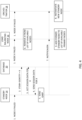
- Figure 3 illustrates an exemplary fail-over procedure used in some embodiments of the present disclosure.
- the standby node 14 When the standby node 14 detects a node failure or receives a failure notification (step 1), it writes the network identity (e.g., IP address) of the failed primary node 12 into the global key STDBY-IDENTITY stored in database 20 (step 2).
- the standby node 14 sends a GET message to the database 20 to request session information for the failed primary node 12 (step 3).
- the database 20 sends the session data for the failed primary node 12 to the standby node 14 (step 4).
- the standby node 14 configures its network interface to use the IP address of the failed primary node 12 and broadcasts a GARP message to the network (step 5).
- the routers in the network will route messages previously sent to the failed primary node 12 to the standby node 14 and the standby node 14 will handle the user sessions of the failed primary node 12.
- the load balancing node 16 When the load balancing node 16 is notified of the failure of a primary node 12, the load balancing node 16 removes the primary node 12 from its list of primary nodes 12 so that no new sessions will be assigned to the failed primary node 12 (step 6).
- the orchestrator 18 instantiates a new instance of the primary node 12 to replace the failed primary node 12 (step 7).
- the standby node 14 is only temporarily active and reverts to a standby mode when a standby timer expires or after the last session assumed by the standby node 14 ends.
- the standby timer expires (step 8), or when the last user session ends, the standby node 14 sends a release notification message to the orchestrater 18 to release the IP address assumed by the standby node 14, so that the IP address is available for reassignment (step 9).
- the standby node 14 also clears the standby identity key stored in the database 20 (step 10).
- FIG 4 illustrates another exemplary fail-over procedure used in some embodiments of the present disclosure where the standby 14 permanently replaces the failed primary node 12.
- Steps 1-6 are the same as the fail-over procedure shown in Figure 3 .
- the standby node 14 sends a notification message to the orchestrator 18 and/or load balancing node 16 to notify the orchestrator 18 and/or load balancing node 16 that it taken over the IP address of the failed primary node 12 (step 7).
- the orchestrator 18 then instantiates a new instance of a standby node 14 to replace the previous standby node 14 (step 8).
- the orchestrator 18 may notify the load balancing node 16 that the standby node 18 is now designated as a primary node 12.
- the load balancing node 16 adds the standby node 14 to its list of available primary nodes 12 in response to the notification from the standby node 14 or orchestrator 18 (step 9).
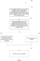
- Figure 5 illustrates an exemplary method 100 implemented by a standby node 14 in a server cluster 10 including a plurality of primary nodes 12.
- the standby node 14 determines that a primary node 12 in a cluster 10 has failed (block 110)
- the standby node 12 configures its network interface to use an IP address of the failed primary node 12 (block 120).
- the standby node 14 further retrieves from a low latency database for the cluster, session data for user sessions associated with the failed primary node 12 (block 130) and restores the user sessions at the standby node 14 (block 140).
- the standby node 14 switches from a standby mode to an active mode (block 150).
- determining that a primary node 12 in a cluster 10 has failed comprises sending a periodic keepalive message to one or more primary nodes 12 in the cluster 10, and determining a node failure when the failed primary node 12 fails to response to a keepalive message.
- determining that a primary node 12 in a cluster has failed comprises receiving a failure notification.
- the failure notification can be received from the database 20.
- configuring the standby node 14 to use an IP address of the failed primary node 12 comprises configuring a network interface to use the IP address of the failed primary node 12.
- configuring the standby node 14 to use an IP address of the failed primary node 12 further comprises announcing a binding between the IP address and a MAC address of the standby node 14.
- Some embodiments of the method 100 further comprise setting a standby identity key in the database to an identity of the failed primary node 12.
- Some embodiments of the method 100 further comprise, after a last one of the user sessions ends, releasing the IP address of the failed primary node 12 and switching from the active mode to the standby mode.
- Some embodiments of the method 100 further comprise, after a last one of the user sessions ends, clearing the standby identity key in the database 20.
- Some embodiments of the method 100 further comprise notifying an orchestrator 18 that the standby node 14 has replaced the failed primary node 12 and receiving new user sessions from a load-balancing node 16.
- Figure 6 illustrates an exemplary method 200 of failure recovery implemented by a primary node 12 in a cluster 10 of network nodes following a temporary failure of the primary node 12.
- the primary node 12 determines whether an IP address of the primary node 12 is being used by a standby node 14 in the cluster 10 of network nodes (block 210).
- the primary node 12 obtains a new IP address or waits for the IP address to be released by the standby node 14 (block 220).
- the primary node 12 reconfigures its network interface with the new IP address and returns to an active mode (block 230, 250).
- the primary node 12 detects release of the IP address by the standby node 14 (block 240) and, responsive to such detection, returns to an active mode (block 250)
- the primary node 12 determines whether an IP address of the primary node 12 is being used by a standby node 14 in the cluster 10 of network nodes by getting a standby identity from a database 20 serving the cluster 10 of network nodes, and comparing the standby identity to an identity of the primary node 12.
- the primary node 12 determines when the IP address is released by monitoring the standby identity stored in the database 20 and determining that the IP address is released when the standby identity is cleared or erased.
- FIG. 7 illustrates an exemplary network node 30 according to an embodiment.
- the network node 30 can be configured as a primary node 12 or as a standby node 14.
- the network node 30 includes a network interface 32 for sending and receiving messages over a communication network, a processing circuit 34, and memory 36
- the processing circuit 34 may comprise one or more microcontrollers, microprocessors, hardware circuits, firmware, or a combination thereof.
- Memory 36 comprises both volatile and non-volatile memory for storing computer program code and data needed by the processing circuit 34 for operation.
- Memory 36 may comprise any tangible, non-transitory computer-readable storage medium for storing data including electronic, magnetic, optical, electromagnetic, or semiconductor data storage.
- Memory 36 stores a computer program 38 comprising executable instructions that configure the processing circuit 34 to implement the procedures and methods as herein described, including one or more of the methods 100, 200 shown in Figures 5 and 6 .
- a computer program 38 in this regard may comprise one or more code modules corresponding to the means or units described above.
- computer program instructions and configuration information are stored in a non-volatile memory, such as a ROM, erasable programmable read only memory (EPROM) or flash memory.
- Temporary data generated during operation may be stored in a volatile memory, such as a random access memory (RAM).
- computer program 38 for configuring the processing circuit 34 as herein described may be stored in a removable memory, such as a portable compact disc, portable digital video disc, or other removable media.
- the computer program 38 may also be embodied in a carrier such as an electronic signal, optical signal, radio signal, or computer readable storage medium.
- memory 38 stores virtualization code executed by the processing circuit 34 for implementing the network node 30 as a virtual machine.
- a computer program comprises instructions which, when executed on at least one processor of an apparatus, cause the apparatus to carry out any of the respective processing described above.
- a computer program in this regard may comprise one or more code modules corresponding to the means or units described above.
- embodiments herein also include a computer program product stored on a non-transitory computer readable (storage or recording) medium and comprising instructions that, when executed by a processor of an apparatus, cause the apparatus to perform as described above.
- Embodiments further include a computer program product comprising program code portions for performing the steps of any of the embodiments herein when the computer program product is executed by a computing device.
- This computer program product may be stored on a computer readable recording medium.
- the methods and apparatus herein described enable provide N+1 redundancy for a cluster of network nodes including a standby node and a plurality of primary nodes.
- a primary node in a cluster has failed, the user sessions can be restored at the standby node.
- the standby node switches from a standby mode to an active mode.
Landscapes
- Engineering & Computer Science (AREA)
- Computer Networks & Wireless Communication (AREA)
- Signal Processing (AREA)
- Health & Medical Sciences (AREA)
- Cardiology (AREA)
- General Health & Medical Sciences (AREA)
- Data Exchanges In Wide-Area Networks (AREA)
- Telephonic Communication Services (AREA)
Description
- This application claims priority to
U.S. Provisional Application No. 62/779313 filed 13 December 2018 U.S. Provisional Application No. 62/770550 filed 21 November 2018 - The present disclosure relates generally to failure protection for communication networks and, more particularly, to a N+1 redundancy scheme for virtualized services with low latency fail-over.
- There are two main failure protection schemes for maintaining continuity of service in the event that a network node in a communication network responsible for handling user traffic fails. The two main protection schemes are 1+1 protection and N+1 protection. With 1+1 protection, N standby nodes are available for N network nodes to take over the function of a failed primary node or nodes. In 1+1 protection schemes, each network node has its own dedicated standby node, which can take over traffic currently being handled by its corresponding network node without loss of sessions. This is known as "hot standby." One drawback of 1+1 protection is that it requires doubling of system resources. With N+1 protection, 1 standby node is available for N network nodes to take over the function of a single failed primary node. However, the N+1 redundancy scheme typically provides only "cold standby" protection so that traffic handled by the failed network node is lost at a switchover." Existing N+1 solutions, don't preserve state of the failed primary node resulting in tear-down of existing sessions. This is because the standby node is not dedicated to any specific one of the N primary nodes, so there was no solution on how to have the state of any one of the primary nodes available in the backup node after the failure. Ultimately, the only benefit is that capacity will not drop after a failure but it does not provide protection for ongoing sessions.
- In case of Virtual Router Redundancy Protocol (VRRP)-based solutions, a standby node may take over the Internet Protocol (IP) address of a failed primary node as well as the functions of the failed primary node, but these solutions do not take over real-time state of the failed primary node that would be needed for preserving session continuity for sockets. Moreover, the operator of the network has to configure separate VRRP sessions with separate IP addresses for each VRRP relationship (i.e., the standby nodes need a separate VRRP context per each primary node it is deemed to protect). This way the configuration overhead in a bigger cluster makes the solution cumbersome.
- Document
US 2006/294241 A1 may be construed to disclose a radio network controller and methods for reestablishing sessions in a wireless network. At least a portion of session information associated with a first session is saved; and in response to detecting an unexpected degradation of the first session, reestablishment of the first session is triggered using the portion of the session information. - The present disclosure comprises methods and apparatus of providing N+1 redundancy for a cluster of network nodes including a standby node and a plurality of primary nodes. When the standby node determines that a primary node in a cluster has failed, the standby node configures the standby node to use an IP address of the failed primary node. The standby node further retrieves session data for user sessions associated with the failed primary node from a low latency database for the cluster and restores the user sessions at the standby node. When the user sessions are restored, the standby node switches from a standby mode to an active mode.
- According to the disclosure, there are provided a method, a network node and a non-transitory computer-readable storage media according to the independent claims. Further developments are set forth in the dependent claims.
- A first aspect of the disclosure comprises methods of providing N+1 redundancy for a cluster of network nodes. In one embodiment, the method comprises determining, by a standby node, that a primary node in a cluster has failed, configuring the standby node to use an IP address of the failed primary node, retrieving session data for user sessions associated with the failed primary node from a low latency database for the cluster, restoring the user sessions at the standby node, and switching from a standby mode to an active mode.
- A second aspect of the disclosure comprise a network node configured as a standby node to provide N+1 protection for a cluster of network nodes including the standby node and a plurality of primary nodes. The standby node comprises a network interface for communicating over a communication network and a processing circuit. The processing circuit is configured to determine that a primary node in a cluster has failed. Responsive to determining that a primary node has failed, the processing circuit configures the standby node to use an IP address of the failed primary node. The processing circuit is further configured to retrieve session data for user sessions associated with the failed primary node from a low latency database for the cluster and restore the user sessions at the standby node. After the user sessions are restored, the processing circuit switches the standby node from a standby mode to an active mode.
- A third aspect of the disclosure comprises a computer program comprising executable instructions that, when executed by a processing circuit in a redundancy controller in a network node, causes the redundancy controller to perform the method according to the first aspect.
-
-
Figure 1 illustrates a server cluster with N+1 redundancy protection. -
Figure 2 graphically illustrates a fail-over. -
Figure 3 illustrates a fail-over procedure according to a first embodiment. -
Figure 4 illustrates a fail-over procedure according to a second embodiment. -
Figure 5 illustrates an exemplary fail-over method implemented by a standby node. -
Figure 6 illustrates an exemplary recovery method implemented by a primary node. -
Figure 7 illustrates an exemplary network node. - Referring now to the drawings,
Figure 1 illustrates aserver cluster 10 with N+1 redundancy protection that implements a virtual network function (VNF), such as a media gateway (MGW) function or Border Gateway Function (BGF). Theserver cluster 10 can be used, for example, in a communication network, such as an Internet Protocol Multimedia Subsystem (IMS) network or other telecom network. Theserver cluster 10 comprises a plurality of network nodes, which include a plurality ofprimary nodes 12 for handling user sessions and astandby node 14 providing N+1 protection in the event that aprimary node 12 fails. Each of thenetwork nodes cluster 10 can be implemented by dedicated hardware and processing resources. Alternatively, thenetwork nodes - User sessions (e.g., telephone calls, media streams, etc.) are distributed among the
primary nodes 12 by aload balancing node 16. Anorchestrator 18 manages theserver cluster 10. A distributed, low-latency database 20 serves as a data store for thecluster 10 to store the states of the user sessions being handled by theprimary nodes 12 as hereinafter described. An exemplary distributeddatabase 20 is described in an article titled "DAL: A Locality-Optimizing Distributed Shared Memory System" by Gabor Nemeth, Daniel Gehberger and Peter Matray. (Németh, Gábor, Dániel Géhberger, and Péter Mátray. "{DAL}: A Locality-Optimizing Distributed Shared Memory System." 9th {USENIX} Workshop on Hot Topics in Cloud Computing (HotCloud 17). Santa Clara, CA - July 10 - 11, 2017). - The
network nodes primary node 12 that handles user traffic for the user session. State information for the user sessions is stored in a distributed, low latency,database 20 that serves theserver cluster 10. In the event that aprimary node 12 fails, thestandby node 14 can retrieve the state information of user sessions handled by the failedprimary node 12 and restore the "lost" user sessions so that service continuity is maintained for the user sessions. -
Figure 2 shows theserver cluster 10 ofFigure 1 in simplified form to graphically illustrates the basic steps of a fail-over procedure. It is assumed inFigure 2 thatPrimary Node 1 has failed. At 1, the failure is detected by thestandby node 14 and the failedprimary node 12 is identified. At 2, the standby node retrieves the state information forPrimary Node 1 from thedatabase 20 and recreates the user sessions at thestandby node 14. At 3, the standby node takes over the IP address ofPrimary Node 1 and configures its network interface to use the IP address. At 4, the standby node advertises the location change of the IP address. Thereafter, the traffic for user sessions associated withIP Address 1 will be routed to thestandby node 14 rather than toPrimary Node 1. - The failure protection scheme used in the present disclosure can be viewed as having three separate phases. In a first phase, referred to as the preparation phase, a redundant system is built so that the system is prepared for failure of a
primary node 12. The second phase comprises a fail-over process in which thestandby node 14, upon detecting a failure of thenprimary node 12, takes over the active user sessions handled by the failedprimary node 12. After the fail-over process is complete, a post-failure process restores capacity and redundancy to the system that is lost by the failure of theprimary node 12 so that backup protection is re-established to protect against future network node failures. - During the preparation phase, state information necessary to restore the user sessions is externalized and stored in the
database 20 by eachprimary node 12. Conventional log-based approaches or checkpointing can be used to externalize the state information. Another suitable method of externalizing state information is described in co-pending application62/770,550 titled "Fast Session Restoration of Latency Sensitive Middleboxes" filed on November 21, 2018 database 20 is dependent on the application and the communication protocol used in the application. For TCP sessions, such state information may comprise port numbers, counters, sequence numbers, various data on Transport Control Protocol (TCP) buffer windows, etc. Generally, all state information that is necessary to continue the user session should be stored externally. - In order to ensure that a backup is readily available to replace a
primary node 12 that has failed, a "warm"standby node 14 is provisioned and made available to take over any user sessions for a failedprimary node 12. During the provisioning, system checks are performed to ensure that: - the image of the
standby node 14 is booted; - the operating system for the
standby node 14 is up and running; - the
standby node 14 has a live connection to thedatabase 20; and - the
standby node 14 shares the same configuration as the other instances and is connected to the same next-hop routers. - It is not known in advance which of the
primary nodes 12 will fail, however, thestandby node 14 is ready to fetch necessary state information from thedatabase 20 to take over for any one of theprimary nodes 12. This standby mode is referred to herein a "warm" standby. - The fail-over process is triggered by the failure of one of the
primary nodes 12. In some embodiments, failure is detected by thestandby node 12 based on a "heartbeat" or "keepalive" signaling. In some embodiments, theprimary nodes 12 may periodically transmit a "heartbeat" signal and a failure is detected when the heartbeat signal is not received by thestandby node 14. In other embodiments, thestandby node 14 may periodically transmit a "keepalive" signal or "ping" message to each of theprimary nodes 12. In this case, a failure is detected when aprimary node 12 fails to respond. This "keepalive" signaling process should be continuously run pairwise between thestandby node 14 and eachprimary node 12. - In other embodiments, the failure of a
primary node 12 can be detected by another network entity and communicated to thestandby node 14 in the form of a failure notification. For example, oneprimary node 12 may detect the failure of anotherprimary node 12 and send a failure notification to thestandby node 14. In another embodiment, thedatabase 20 may detect the failure of aprimary node 12 and send a failure notification to thestandby node 14. - When a fail-over is triggered, the
standby node 14 retrieves the IP address or addresses of the failedprimary node 12, as well as the session states (e.g., application and protocol dependent context data) necessary to re-initiate the user sessions at thestandby node 14. In some embodiments, thestandby node 14 writes the network identify (e.g., IP address) of the failedprimary node 12 into a global key called STDBY-IDENTITY, which is stored in thedatabase 20 so that all nodes in theserver cluster 10 are aware that thestandby node 14 has assumed the role of the failedprimary node 12. Responsive to the failure detection or failure indication, thestandby node 14 configures its network interface to use the IP address or addresses of the failedprimary node 12 and loads the retrieved session states into its own tables. When thestandby node 14 is ready to take over, thestandby node 14 broadcasts a Gratuitous Address Resolution Protocol (GARP) message with its own Medium Access Control (MAC) address and its newly configured IP address(es), so that the routers in the subnet know to forward packets with the IP address(es) formerly used by the failedprimary node 12 to the standby node's MAC address. The same general principles also apply to Internet Protocol version 6 (IPv6) interfaces (Unsolicited Neighbor Advertisement message). - During the post-failure phase, the original capacity of the
server cluster 10 with Nprimary nodes standby node 14 is restored. There are essentially two alternative approaches to restoring the system capacity. - In a first approach for the post-failure phase, the
standby node 14 switches from a standby mode to an active mode and serves only temporarily as a primary node, reverting to a "warm" standby mode when done. Thestandby node 14 serves only the user sessions that were taken over from the failedprimary node 12 and is not assigned to handle any new user sessions by theload balancing node 16. When the orchestrator 18 learns about the failure of aprimary node 12, it re-establishes a newprimary node 12 to replace the failedprimary node 12 and restore system capacity according to a regular scale-out procedure. The orchestrator 18 should ensure that the IP addresses used by the failedprimary node 12 on the user plane are reserved, because these addresses are taken over by thestandby node 14. In case of an OpenStack-basedorchestrator 18, reserving the IP addresses means that the "ports" should not be deleted when the failedprimary node 12 disappears. This requires, however, garbage collection. Thestandby node 14, when it terminates, sends a trigger to the orchestrator 18 indicating that the ports used by the affected IP addresses can be deleted. After this notification, the IP addresses can be assigned to new network nodes (e.g., VNFs). - During the post-failure phase, the operation of the
load balancing node 18 needs to take into account the failedprimary node 12. Immediately after the failure, however, theload balancing node 18 does not assign new incoming sessions to either the failedprimary node 12 or thestandby node 14. As noted above, thestandby node 14 continues serving existing user sessions taken over from the failedprimary node 12, but does not receive new sessions. After the last session is finished at thestandby node 14, or upon expiration of a timer (MAX_STANDBY_LIFETIME), thestandby node 14 erases or clears the STDBY_IDENTITY field in thedatabase 20, sends a notification to the orchestrator 18 indicating that the IP addresses of X can be released, and transitions back to a "warm" standby mode. The MAX_STANDBY_LIFETIME timer, if used, is started when thestandby node 14 takes over for the failedprimary node 12. - In a second approach for the post-failure phase, the
standby node 14 permanently assumes the role of the failedprimary node 12 and the orchestrator re-establishes system capacity by initiating anew standby node 14. In this case, Thestandby node 14 sends a notification message or other indication to the orchestrator 18 indicating that the IP address(es) of the failedprimary node 12 were assumed or taken over by thestandby node 14 so that the orchestrator 18 knows (i) to whichprimary node 12 the IP addresses belong, and (ii) that these IP addresses cannot be used for new instances of theprimary nodes 12 in case of a scale-out. The standby node 14 (now fully a primary node 12) triggers the orchestrator 18 to launch a new instance for thestandby node 14 to restore the original redundancy protection. - There may be circumstance where
primary node 12 fails only temporarily, typically because of a VM reboot. Following the restart, theprimary node 12 may try to use its earlier IP address(es), which would cause a conflict with thestandby node 14 that is serving the ongoing user sessions associated with those addresses. Before restarting, the primary node reads the STDBY_IDENTITY key in thedatabase 20. If the STDBY_IDENTITY key matches the identity of theprimary node 12, theprimary node 12 pauses and waits until the key is erased, indicating that the IP address used by the standby node has been released, or asks for new configuration parameters from theorchestrator 18. -
Figure 3 illustrates an exemplary fail-over procedure used in some embodiments of the present disclosure. When thestandby node 14 detects a node failure or receives a failure notification (step 1), it writes the network identity (e.g., IP address) of the failedprimary node 12 into the global key STDBY-IDENTITY stored in database 20 (step 2). Thestandby node 14 sends a GET message to thedatabase 20 to request session information for the failed primary node 12 (step 3). In response to the GET message, thedatabase 20 sends the session data for the failedprimary node 12 to the standby node 14 (step 4). As previously described, thestandby node 14 configures its network interface to use the IP address of the failedprimary node 12 and broadcasts a GARP message to the network (step 5). Upon broadcast of the GARP message, the routers in the network will route messages previously sent to the failedprimary node 12 to thestandby node 14 and thestandby node 14 will handle the user sessions of the failedprimary node 12. When theload balancing node 16 is notified of the failure of aprimary node 12, theload balancing node 16 removes theprimary node 12 from its list ofprimary nodes 12 so that no new sessions will be assigned to the failed primary node 12 (step 6). Also, when theorchestrator 18 is notified of the failure of aprimary node 12, theorchestrator 18 instantiates a new instance of theprimary node 12 to replace the failed primary node 12 (step 7). - In the embodiment shown in
Figure 3 , it is assumed that thestandby node 14 is only temporarily active and reverts to a standby mode when a standby timer expires or after the last session assumed by thestandby node 14 ends. In this case, when the standby timer expires (step 8), or when the last user session ends, thestandby node 14 sends a release notification message to theorchestrater 18 to release the IP address assumed by thestandby node 14, so that the IP address is available for reassignment (step 9). Thestandby node 14 also clears the standby identity key stored in the database 20 (step 10). -
Figure 4 illustrates another exemplary fail-over procedure used in some embodiments of the present disclosure where thestandby 14 permanently replaces the failedprimary node 12. Steps 1-6 are the same as the fail-over procedure shown inFigure 3 . After becoming active, thestandby node 14 sends a notification message to theorchestrator 18 and/or load balancingnode 16 to notify theorchestrator 18 and/or load balancingnode 16 that it taken over the IP address of the failed primary node 12 (step 7). The orchestrator 18 then instantiates a new instance of astandby node 14 to replace the previous standby node 14 (step 8). In some embodiments, theorchestrator 18 may notify theload balancing node 16 that thestandby node 18 is now designated as aprimary node 12. Theload balancing node 16 adds thestandby node 14 to its list of availableprimary nodes 12 in response to the notification from thestandby node 14 or orchestrator 18 (step 9). -
Figure 5 illustrates anexemplary method 100 implemented by astandby node 14 in aserver cluster 10 including a plurality ofprimary nodes 12. When thestandby node 14 determines that aprimary node 12 in acluster 10 has failed (block 110), thestandby node 12 configures its network interface to use an IP address of the failed primary node 12 (block 120). Thestandby node 14 further retrieves from a low latency database for the cluster, session data for user sessions associated with the failed primary node 12 (block 130) and restores the user sessions at the standby node 14 (block 140). When the user sessions are restored, thestandby node 14 switches from a standby mode to an active mode (block 150). - In some embodiments of the
method 100, determining that aprimary node 12 in acluster 10 has failed comprises sending a periodic keepalive message to one or moreprimary nodes 12 in thecluster 10, and determining a node failure when the failedprimary node 12 fails to response to a keepalive message. - In some embodiments of the
method 100, determining that aprimary node 12 in a cluster has failed comprises receiving a failure notification. As an example, the failure notification can be received from thedatabase 20. - In some embodiments of the
method 100, configuring thestandby node 14 to use an IP address of the failedprimary node 12 comprises configuring a network interface to use the IP address of the failedprimary node 12. - In some embodiments of the
method 100, configuring thestandby node 14 to use an IP address of the failedprimary node 12 further comprises announcing a binding between the IP address and a MAC address of thestandby node 14. - Some embodiments of the
method 100 further comprise setting a standby identity key in the database to an identity of the failedprimary node 12. - Some embodiments of the
method 100 further comprise, after a last one of the user sessions ends, releasing the IP address of the failedprimary node 12 and switching from the active mode to the standby mode. - Some embodiments of the
method 100 further comprise, after a last one of the user sessions ends, clearing the standby identity key in thedatabase 20. - Some embodiments of the
method 100 further comprise notifying an orchestrator 18 that thestandby node 14 has replaced the failedprimary node 12 and receiving new user sessions from a load-balancingnode 16. -
Figure 6 illustrates anexemplary method 200 of failure recovery implemented by aprimary node 12 in acluster 10 of network nodes following a temporary failure of theprimary node 12. Following a restart by theprimary node 12, theprimary node 12 determines whether an IP address of theprimary node 12 is being used by astandby node 14 in thecluster 10 of network nodes (block 210). Upon determining that the IP address is being used by astandby node 14, theprimary node 12 obtains a new IP address or waits for the IP address to be released by the standby node 14 (block 220). In the former case, theprimary node 12 reconfigures its network interface with the new IP address and returns to an active mode (block 230, 250). In the latter case, theprimary node 12 detects release of the IP address by the standby node 14 (block 240) and, responsive to such detection, returns to an active mode (block 250) - The
primary node 12 determines whether an IP address of theprimary node 12 is being used by astandby node 14 in thecluster 10 of network nodes by getting a standby identity from adatabase 20 serving thecluster 10 of network nodes, and comparing the standby identity to an identity of theprimary node 12. - The
primary node 12 determines when the IP address is released by monitoring the standby identity stored in thedatabase 20 and determining that the IP address is released when the standby identity is cleared or erased. -
Figure 7 illustrates anexemplary network node 30 according to an embodiment. Thenetwork node 30 can be configured as aprimary node 12 or as astandby node 14. Thenetwork node 30 includes a network interface 32 for sending and receiving messages over a communication network, aprocessing circuit 34, andmemory 36 Theprocessing circuit 34 may comprise one or more microcontrollers, microprocessors, hardware circuits, firmware, or a combination thereof.Memory 36 comprises both volatile and non-volatile memory for storing computer program code and data needed by theprocessing circuit 34 for operation.Memory 36 may comprise any tangible, non-transitory computer-readable storage medium for storing data including electronic, magnetic, optical, electromagnetic, or semiconductor data storage.Memory 36 stores acomputer program 38 comprising executable instructions that configure theprocessing circuit 34 to implement the procedures and methods as herein described, including one or more of themethods Figures 5 and6 . Acomputer program 38 in this regard may comprise one or more code modules corresponding to the means or units described above. In general, computer program instructions and configuration information are stored in a non-volatile memory, such as a ROM, erasable programmable read only memory (EPROM) or flash memory. Temporary data generated during operation may be stored in a volatile memory, such as a random access memory (RAM). In some embodiments,computer program 38 for configuring theprocessing circuit 34 as herein described may be stored in a removable memory, such as a portable compact disc, portable digital video disc, or other removable media. Thecomputer program 38 may also be embodied in a carrier such as an electronic signal, optical signal, radio signal, or computer readable storage medium. In some embodiments,memory 38 stores virtualization code executed by theprocessing circuit 34 for implementing thenetwork node 30 as a virtual machine. - Those skilled in the art will also appreciate that embodiments herein further include corresponding computer programs. A computer program comprises instructions which, when executed on at least one processor of an apparatus, cause the apparatus to carry out any of the respective processing described above. A computer program in this regard may comprise one or more code modules corresponding to the means or units described above.
- In this regard, embodiments herein also include a computer program product stored on a non-transitory computer readable (storage or recording) medium and comprising instructions that, when executed by a processor of an apparatus, cause the apparatus to perform as described above.
- Embodiments further include a computer program product comprising program code portions for performing the steps of any of the embodiments herein when the computer program product is executed by a computing device. This computer program product may be stored on a computer readable recording medium.
- The methods and apparatus herein described enable provide N+1 redundancy for a cluster of network nodes including a standby node and a plurality of primary nodes. When a primary node in a cluster has failed, the user sessions can be restored at the standby node. When the user sessions are restored, the standby node switches from a standby mode to an active mode.
Claims (10)
- A method (100) of providing N+1 redundancy for a cluster (10) of network nodes including a standby node (14, 30) and a plurality of primary nodes (12, 30), the method (100) being performed by the standby node (14, 30) and comprising:determining (110), by the standby node (14, 30), that one of the primary nodes (12, 30) in the cluster (10) has failed;configuring (120) the standby node (14, 30) to use an Internet Protocol, IP, address of the failed primary node (12, 30), comprising:- configuring a network interface (32) of the standby node (14, 30) to use the IP address of the failed primary node (12, 30); and- announcing a binding between the IP address and a Medium Access Control, MAC, address of the standby node (14, 30);retrieving (130), from a low latency database (20) for the cluster (10), session data for user sessions associated with the failed primary node (12, 30);restoring (140) the user sessions at the standby node (14, 30); andswitching (150) from a standby mode to an active mode.
- The method (100) of claim 1 wherein:
determining (110) that a primary node (12, 30) in a cluster (10) has failed comprises sending a periodic keepalive message to one or more primary nodes (12, 30) in the cluster (10); and determining a node failure when the failed primary node (12, 30) fails to respond to a keepalive message. - The method (100) of claim 1 wherein:
determining (110) that a primary node (12, 30) in a cluster (10) has failed comprises receiving a failure notification. - The method (100) of claim 3, wherein the failure notification is received from the external database (20).
- The method (100) of any one of claims 1 to 4 further comprising setting a standby identity key in the database (20) to an identity of the failed primary node (12, 30).
- The method (100) of any one of claims 1 to 5 further comprising:after a last one of the user sessions ends: releasing the IP address of the failed primary node (12, 30); and switching from the active mode to the standby mode; orupon expiration of a standby timer: releasing the IP address of the failed primary node (12, 30); and switching from the active mode to the standby mode.
- The method (100) of any one of claims 1 to 5 further comprising:
notifying an orchestrator (18) that the standby node (14, 30) has replaced the failed primary node (12, 30); and receiving new user sessions from a load-balancing node (916). - The method (100) of claim 6, further comprising, after a last one of the user sessions ends or upon expiration of a standby timer, clearing the standby identity key in the database (20).
- A network node (14, 30) providing N+1 protection for a plurality of primary nodes (12, 30) in a cluster (10) including a standby node (14, 30) and a plurality of primary nodes (12, 30), the network node (14, 30) being the standby node (14, 30) and comprising:
a network interface (32) configured to perform all steps of a method according to any one of claims 1 to 8. - A non-transitory computer-readable storage medium containing a computer program comprising executable instructions that, when executed by a processing circuit (34) in a network node of a mobile network causes the network node to perform any one of the methods of claims 1 to 8.
Applications Claiming Priority (3)
| Application Number | Priority Date | Filing Date | Title |
|---|---|---|---|
| US201862770550P | 2018-11-21 | 2018-11-21 | |
| US201862779313P | 2018-12-13 | 2018-12-13 | |
| PCT/IB2019/060037 WO2020104992A1 (en) | 2018-11-21 | 2019-11-21 | N+1 redundancy for virtualized services with low latency fail-over |
Publications (2)
| Publication Number | Publication Date |
|---|---|
| EP3884619A1 EP3884619A1 (en) | 2021-09-29 |
| EP3884619B1 true EP3884619B1 (en) | 2025-01-01 |
Family
ID=68699490
Family Applications (2)
| Application Number | Title | Priority Date | Filing Date |
|---|---|---|---|
| EP19813146.8A Pending EP3884620A1 (en) | 2018-11-21 | 2019-11-21 | Fast session restoration for latency sensitive middleboxes |
| EP19809923.6A Active EP3884619B1 (en) | 2018-11-21 | 2019-11-21 | N+1 redundancy for virtualized services with low latency fail-over |
Family Applications Before (1)
| Application Number | Title | Priority Date | Filing Date |
|---|---|---|---|
| EP19813146.8A Pending EP3884620A1 (en) | 2018-11-21 | 2019-11-21 | Fast session restoration for latency sensitive middleboxes |
Country Status (4)
| Country | Link |
|---|---|
| US (2) | US20220006868A1 (en) |
| EP (2) | EP3884620A1 (en) |
| CN (1) | CN113169895A (en) |
| WO (2) | WO2020104988A1 (en) |
Families Citing this family (14)
| Publication number | Priority date | Publication date | Assignee | Title |
|---|---|---|---|---|
| EP3884620A1 (en) | 2018-11-21 | 2021-09-29 | Telefonaktiebolaget LM Ericsson (publ) | Fast session restoration for latency sensitive middleboxes |
| CN112448858B (en) * | 2021-02-01 | 2021-04-23 | 腾讯科技(深圳)有限公司 | Network communication control method and apparatus, electronic device and readable storage medium |
| CN113891358B (en) * | 2021-09-30 | 2024-04-16 | 杭州阿里云飞天信息技术有限公司 | Cloud network load balancing method, device and storage medium |
| CN114422567B (en) * | 2021-12-09 | 2024-10-11 | 阿里巴巴(中国)有限公司 | Data request processing method, device, system, computer equipment and medium |
| CN114301763B (en) * | 2021-12-15 | 2024-07-26 | 山石网科通信技术股份有限公司 | Distributed cluster fault processing method and system, electronic equipment and storage medium |
| CN115567366B (en) * | 2022-09-19 | 2026-06-05 | 中国工商银行股份有限公司 | Methods, devices, storage media, and electronic equipment for analyzing the impact of network failures |
| EP4670376A1 (en) * | 2023-02-24 | 2025-12-31 | Jio Platforms Limited | SYSTEM AND METHOD FOR TRANSMITTING 5G NAS MESSAGES USING A SHORT MESSAGE SERVICE FUNCTION |
| EP4721357A1 (en) * | 2023-05-31 | 2026-04-08 | Boost SubscriberCo L.L.C. | System and method to reduce network function interruptions in a service-based architecture |
| US12348355B2 (en) * | 2023-05-31 | 2025-07-01 | Dish Wireless L.L.C. | System and method to reduce database interruptions in a service-based architecture |
| US20240407025A1 (en) * | 2023-05-31 | 2024-12-05 | Dish Wireless L.L.C. | System And Method To Reduce Network Function Interruptions In A Service-Based Architecture |
| US12549433B2 (en) | 2023-05-31 | 2026-02-10 | Boost SubscriberCo L.L.C. | System and method to reduce network function interruptions in a service-based architecture |
| CN117076196A (en) * | 2023-08-14 | 2023-11-17 | 京东科技信息技术有限公司 | A management and control method and device for database disaster recovery |
| US12481341B2 (en) | 2023-10-11 | 2025-11-25 | International Business Machines Corporation | Distributed phase redundancy |
| CN122316885A (en) * | 2024-12-30 | 2026-06-30 | 宁德时代未来能源(上海)研究院有限公司 | Data acquisition methods, devices, systems, equipment and storage media |
Citations (4)
| Publication number | Priority date | Publication date | Assignee | Title |
|---|---|---|---|---|
| US20060294241A1 (en) * | 2005-06-24 | 2006-12-28 | Sanjay Cherian | Preserving sessions in a wireless network |
| US20080151892A1 (en) * | 2006-12-21 | 2008-06-26 | Verizon Services Corp. | Method, Copumter Program Product, and Apparatus for Providing Passive Automated Provisioning |
| US20090254775A1 (en) * | 2008-04-02 | 2009-10-08 | International Business Machines Corporation | Method for enabling faster recovery of client applications in the event of server failure |
| US20130107872A1 (en) * | 2004-02-13 | 2013-05-02 | Thomas Dean Lovett | Processor-memory module performance acceleration in fabric-backplane enterprise servers |
Family Cites Families (29)
| Publication number | Priority date | Publication date | Assignee | Title |
|---|---|---|---|---|
| US6189111B1 (en) * | 1997-03-28 | 2001-02-13 | Tandem Computers Incorporated | Resource harvesting in scalable, fault tolerant, single system image clusters |
| US7444335B1 (en) * | 2001-02-28 | 2008-10-28 | Oracle International Corporation | System and method for providing cooperative resource groups for high availability applications |
| US20040107382A1 (en) | 2002-07-23 | 2004-06-03 | Att Corp. | Method for network layer restoration using spare interfaces connected to a reconfigurable transport network |
| US7483374B2 (en) | 2003-08-05 | 2009-01-27 | Scalent Systems, Inc. | Method and apparatus for achieving dynamic capacity and high availability in multi-stage data networks using adaptive flow-based routing |
| US7246256B2 (en) * | 2004-01-20 | 2007-07-17 | International Business Machines Corporation | Managing failover of J2EE compliant middleware in a high availability system |
| US7716274B1 (en) * | 2004-04-14 | 2010-05-11 | Oracle America, Inc. | State data persistence in a distributed computing environment |
| US7916855B2 (en) | 2005-01-07 | 2011-03-29 | Cisco Technology, Inc. | System and method for storing and restoring communication dialog |
| US20070104198A1 (en) * | 2005-11-10 | 2007-05-10 | Kumar Kalluri | Apparatus and method for providing a high availability network mechanish |
| US8248916B2 (en) * | 2005-12-30 | 2012-08-21 | Telefonaktiebolaget Lm Ericsson (Publ) | Recovery methods for restoring service in a distributed radio access network |
| US7953861B2 (en) | 2006-08-10 | 2011-05-31 | International Business Machines Corporation | Managing session state for web applications |
| US8306951B2 (en) * | 2009-09-18 | 2012-11-06 | Oracle International Corporation | Automated integrated high availability of the in-memory database cache and the backend enterprise database |
| CN103535072B (en) | 2011-03-18 | 2017-02-15 | 阿尔卡特朗讯公司 | System and method for session resiliancy at geo-redundant gateways |
| WO2012137044A1 (en) * | 2011-04-07 | 2012-10-11 | Telefonaktiebolaget L M Ericsson (Publ) | Ethernet based local ip access |
| US8751641B2 (en) * | 2011-09-15 | 2014-06-10 | International Business Machines Corporation | Optimizing clustered network attached storage (NAS) usage |
| US8918673B1 (en) | 2012-06-14 | 2014-12-23 | Symantec Corporation | Systems and methods for proactively evaluating failover nodes prior to the occurrence of failover events |
| CN102938705B (en) | 2012-09-25 | 2015-03-11 | 上海证券交易所 | Method for managing and switching high availability multi-machine backup routing table |
| US9755889B2 (en) | 2013-02-13 | 2017-09-05 | International Business Machines Corporation | Service failover and failback using enterprise service bus |
| US9497281B2 (en) | 2013-04-06 | 2016-11-15 | Citrix Systems, Inc. | Systems and methods to cache packet steering decisions for a cluster of load balancers |
| US9298560B2 (en) | 2013-05-16 | 2016-03-29 | Tektronix Texas, Inc. | System and method for GTP session persistence and recovery |
| US10560535B2 (en) * | 2015-05-21 | 2020-02-11 | Dell Products, Lp | System and method for live migration of remote desktop session host sessions without data loss |
| US9727486B1 (en) * | 2015-09-10 | 2017-08-08 | Infinidat Ltd. | Writing pages to a storage system |
| WO2017207049A1 (en) | 2016-06-01 | 2017-12-07 | Telefonaktiebolaget Lm Ericsson (Publ) | A node of a network and a method of operating the same for resource distribution |
| US10601779B1 (en) * | 2016-06-21 | 2020-03-24 | Amazon Technologies, Inc. | Virtual private network (VPN) service backed by eventually consistent regional database |
| US10817196B2 (en) * | 2017-07-07 | 2020-10-27 | Sap Se | Page list based crash recovery |
| CN107454155B (en) * | 2017-07-25 | 2021-01-22 | 北京三快在线科技有限公司 | Fault processing method, device and system based on load balancing cluster |
| US10411948B2 (en) | 2017-08-14 | 2019-09-10 | Nicira, Inc. | Cooperative active-standby failover between network systems |
| US11334468B2 (en) | 2017-12-14 | 2022-05-17 | Telefonaktiebolaget Lm Ericsson (Publ) | Checking a correct operation of an application in a cloud environment |
| EP3884620A1 (en) | 2018-11-21 | 2021-09-29 | Telefonaktiebolaget LM Ericsson (publ) | Fast session restoration for latency sensitive middleboxes |
| US11171861B2 (en) * | 2019-12-23 | 2021-11-09 | Arista Networks, Inc. | Fast failover and recovery for overlay networks |
-
2019
- 2019-11-21 EP EP19813146.8A patent/EP3884620A1/en active Pending
- 2019-11-21 EP EP19809923.6A patent/EP3884619B1/en active Active
- 2019-11-21 WO PCT/IB2019/060031 patent/WO2020104988A1/en not_active Ceased
- 2019-11-21 CN CN201980076569.7A patent/CN113169895A/en active Pending
- 2019-11-21 WO PCT/IB2019/060037 patent/WO2020104992A1/en not_active Ceased
- 2019-11-21 US US17/295,645 patent/US20220006868A1/en active Pending
- 2019-11-21 US US17/293,984 patent/US11917023B2/en active Active
Patent Citations (4)
| Publication number | Priority date | Publication date | Assignee | Title |
|---|---|---|---|---|
| US20130107872A1 (en) * | 2004-02-13 | 2013-05-02 | Thomas Dean Lovett | Processor-memory module performance acceleration in fabric-backplane enterprise servers |
| US20060294241A1 (en) * | 2005-06-24 | 2006-12-28 | Sanjay Cherian | Preserving sessions in a wireless network |
| US20080151892A1 (en) * | 2006-12-21 | 2008-06-26 | Verizon Services Corp. | Method, Copumter Program Product, and Apparatus for Providing Passive Automated Provisioning |
| US20090254775A1 (en) * | 2008-04-02 | 2009-10-08 | International Business Machines Corporation | Method for enabling faster recovery of client applications in the event of server failure |
Also Published As
| Publication number | Publication date |
|---|---|
| US20220006868A1 (en) | 2022-01-06 |
| US11917023B2 (en) | 2024-02-27 |
| EP3884619A1 (en) | 2021-09-29 |
| EP3884620A1 (en) | 2021-09-29 |
| US20220124159A1 (en) | 2022-04-21 |
| WO2020104988A1 (en) | 2020-05-28 |
| WO2020104992A1 (en) | 2020-05-28 |
| CN113169895A (en) | 2021-07-23 |
Similar Documents
| Publication | Publication Date | Title |
|---|---|---|
| US20220006868A1 (en) | N+1 Redundancy for Virtualized Services with Low Latency Fail-Over | |
| US10397045B2 (en) | Method for migrating service of data center, apparatus, and system | |
| US9219641B2 (en) | Performing failover in a redundancy group | |
| EP3114799B1 (en) | Method and system for seamless sctp-server failover between sctp servers running on different machines | |
| TWI736657B (en) | Method and device for switching virtual internet protocol address | |
| US20190028538A1 (en) | Method, apparatus, and system for controlling service traffic between data centers | |
| CN107888636B (en) | Data processing method and system based on cloud storage | |
| EP2731010A1 (en) | Method, device, and system for migrating configuration information during live migration of virtual machine | |
| US10367680B2 (en) | Network relay apparatus, gateway redundancy system, program, and redundancy method | |
| US11349706B2 (en) | Two-channel-based high-availability | |
| CN104038376A (en) | Method and device for managing real servers and LVS clustering system | |
| EP3474501B1 (en) | Network device stacking | |
| US11405352B2 (en) | Fast relearning of workload MAC addresses multi-homed to active and backup gateways | |
| CN114301842B (en) | Route searching method and device, storage medium, processor and network system | |
| CN110417599B (en) | Main/standby node switching method and node server | |
| JP2009278436A (en) | Communication system and redundant configuration management method | |
| CN108768798B (en) | Equipment access method and device | |
| KR20180099143A (en) | Apparatus and method for recovering tcp-session | |
| US20250126054A1 (en) | Fast media flow failover in layer 4 networks | |
| CN114301763A (en) | Distributed cluster fault processing method and system, electronic device and storage medium | |
| CN117938800A (en) | Method, device and computer program product for rapidly switching IP addresses | |
| HK40066746B (en) | Cloud server live migration method, virtual switch and software defined network architecture | |
| CN119254694A (en) | A method for determining a master router and related devices | |
| CN120186043A (en) | Flow data processing method, control message processing method and electronic device |
Legal Events
| Date | Code | Title | Description |
|---|---|---|---|
| STAA | Information on the status of an ep patent application or granted ep patent |
Free format text: STATUS: UNKNOWN |
|
| STAA | Information on the status of an ep patent application or granted ep patent |
Free format text: STATUS: THE INTERNATIONAL PUBLICATION HAS BEEN MADE |
|
| PUAI | Public reference made under article 153(3) epc to a published international application that has entered the european phase |
Free format text: ORIGINAL CODE: 0009012 |
|
| STAA | Information on the status of an ep patent application or granted ep patent |
Free format text: STATUS: REQUEST FOR EXAMINATION WAS MADE |
|
| 17P | Request for examination filed |
Effective date: 20210609 |
|
| AK | Designated contracting states |
Kind code of ref document: A1 Designated state(s): AL AT BE BG CH CY CZ DE DK EE ES FI FR GB GR HR HU IE IS IT LI LT LU LV MC MK MT NL NO PL PT RO RS SE SI SK SM TR |
|
| DAV | Request for validation of the european patent (deleted) | ||
| DAX | Request for extension of the european patent (deleted) | ||
| REG | Reference to a national code |
Ref country code: DE Ref legal event code: R079 Free format text: PREVIOUS MAIN CLASS: H04L0012240000 Ipc: H04L0041065400 Ref document number: 602019064329 Country of ref document: DE |
|
| PUAG | Search results despatched under rule 164(2) epc together with communication from examining division |
Free format text: ORIGINAL CODE: 0009017 |
|
| STAA | Information on the status of an ep patent application or granted ep patent |
Free format text: STATUS: EXAMINATION IS IN PROGRESS |
|
| 17Q | First examination report despatched |
Effective date: 20240321 |
|
| B565 | Issuance of search results under rule 164(2) epc |
Effective date: 20240321 |
|
| RIC1 | Information provided on ipc code assigned before grant |
Ipc: H04L 67/148 20220101ALI20240318BHEP Ipc: H04L 67/146 20220101ALI20240318BHEP Ipc: H04L 67/142 20220101ALI20240318BHEP Ipc: H04L 67/1097 20220101ALI20240318BHEP Ipc: H04L 41/0654 20220101AFI20240318BHEP |
|
| GRAP | Despatch of communication of intention to grant a patent |
Free format text: ORIGINAL CODE: EPIDOSNIGR1 |
|
| STAA | Information on the status of an ep patent application or granted ep patent |
Free format text: STATUS: GRANT OF PATENT IS INTENDED |
|
| RIC1 | Information provided on ipc code assigned before grant |
Ipc: H04L 67/148 20220101ALI20240522BHEP Ipc: H04L 67/146 20220101ALI20240522BHEP Ipc: H04L 67/142 20220101ALI20240522BHEP Ipc: H04L 67/1097 20220101ALI20240522BHEP Ipc: H04L 41/0654 20220101AFI20240522BHEP |
|
| INTG | Intention to grant announced |
Effective date: 20240605 |
|
| GRAS | Grant fee paid |
Free format text: ORIGINAL CODE: EPIDOSNIGR3 |
|
| GRAA | (expected) grant |
Free format text: ORIGINAL CODE: 0009210 |
|
| STAA | Information on the status of an ep patent application or granted ep patent |
Free format text: STATUS: THE PATENT HAS BEEN GRANTED |
|
| AK | Designated contracting states |
Kind code of ref document: B1 Designated state(s): AL AT BE BG CH CY CZ DE DK EE ES FI FR GB GR HR HU IE IS IT LI LT LU LV MC MK MT NL NO PL PT RO RS SE SI SK SM TR |
|
| REG | Reference to a national code |
Ref country code: GB Ref legal event code: FG4D |
|
| REG | Reference to a national code |
Ref country code: CH Ref legal event code: EP |
|
| REG | Reference to a national code |
Ref country code: DE Ref legal event code: R096 Ref document number: 602019064329 Country of ref document: DE |
|
| REG | Reference to a national code |
Ref country code: IE Ref legal event code: FG4D |
|
| REG | Reference to a national code |
Ref country code: LT Ref legal event code: MG9D |
|
| REG | Reference to a national code |
Ref country code: NL Ref legal event code: MP Effective date: 20250101 |
|
| REG | Reference to a national code |
Ref country code: AT Ref legal event code: MK05 Ref document number: 1757446 Country of ref document: AT Kind code of ref document: T Effective date: 20250101 |
|
| PG25 | Lapsed in a contracting state [announced via postgrant information from national office to epo] |
Ref country code: NL Free format text: LAPSE BECAUSE OF FAILURE TO SUBMIT A TRANSLATION OF THE DESCRIPTION OR TO PAY THE FEE WITHIN THE PRESCRIBED TIME-LIMIT Effective date: 20250101 |
|
| PG25 | Lapsed in a contracting state [announced via postgrant information from national office to epo] |
Ref country code: FI Free format text: LAPSE BECAUSE OF FAILURE TO SUBMIT A TRANSLATION OF THE DESCRIPTION OR TO PAY THE FEE WITHIN THE PRESCRIBED TIME-LIMIT Effective date: 20250101 |
|
| PG25 | Lapsed in a contracting state [announced via postgrant information from national office to epo] |
Ref country code: PL Free format text: LAPSE BECAUSE OF FAILURE TO SUBMIT A TRANSLATION OF THE DESCRIPTION OR TO PAY THE FEE WITHIN THE PRESCRIBED TIME-LIMIT Effective date: 20250101 |
|
| PG25 | Lapsed in a contracting state [announced via postgrant information from national office to epo] |
Ref country code: ES Free format text: LAPSE BECAUSE OF FAILURE TO SUBMIT A TRANSLATION OF THE DESCRIPTION OR TO PAY THE FEE WITHIN THE PRESCRIBED TIME-LIMIT Effective date: 20250101 |
|
| PG25 | Lapsed in a contracting state [announced via postgrant information from national office to epo] |
Ref country code: IS Free format text: LAPSE BECAUSE OF FAILURE TO SUBMIT A TRANSLATION OF THE DESCRIPTION OR TO PAY THE FEE WITHIN THE PRESCRIBED TIME-LIMIT Effective date: 20250501 Ref country code: NO Free format text: LAPSE BECAUSE OF FAILURE TO SUBMIT A TRANSLATION OF THE DESCRIPTION OR TO PAY THE FEE WITHIN THE PRESCRIBED TIME-LIMIT Effective date: 20250401 |
|
| PG25 | Lapsed in a contracting state [announced via postgrant information from national office to epo] |
Ref country code: HR Free format text: LAPSE BECAUSE OF FAILURE TO SUBMIT A TRANSLATION OF THE DESCRIPTION OR TO PAY THE FEE WITHIN THE PRESCRIBED TIME-LIMIT Effective date: 20250101 |
|
| PG25 | Lapsed in a contracting state [announced via postgrant information from national office to epo] |
Ref country code: LV Free format text: LAPSE BECAUSE OF FAILURE TO SUBMIT A TRANSLATION OF THE DESCRIPTION OR TO PAY THE FEE WITHIN THE PRESCRIBED TIME-LIMIT Effective date: 20250101 Ref country code: PT Free format text: LAPSE BECAUSE OF FAILURE TO SUBMIT A TRANSLATION OF THE DESCRIPTION OR TO PAY THE FEE WITHIN THE PRESCRIBED TIME-LIMIT Effective date: 20250502 |
|
| PG25 | Lapsed in a contracting state [announced via postgrant information from national office to epo] |
Ref country code: GR Free format text: LAPSE BECAUSE OF FAILURE TO SUBMIT A TRANSLATION OF THE DESCRIPTION OR TO PAY THE FEE WITHIN THE PRESCRIBED TIME-LIMIT Effective date: 20250402 Ref country code: BG Free format text: LAPSE BECAUSE OF FAILURE TO SUBMIT A TRANSLATION OF THE DESCRIPTION OR TO PAY THE FEE WITHIN THE PRESCRIBED TIME-LIMIT Effective date: 20250101 |
|
| PG25 | Lapsed in a contracting state [announced via postgrant information from national office to epo] |
Ref country code: AT Free format text: LAPSE BECAUSE OF FAILURE TO SUBMIT A TRANSLATION OF THE DESCRIPTION OR TO PAY THE FEE WITHIN THE PRESCRIBED TIME-LIMIT Effective date: 20250101 |
|
| PG25 | Lapsed in a contracting state [announced via postgrant information from national office to epo] |
Ref country code: CZ Free format text: LAPSE BECAUSE OF FAILURE TO SUBMIT A TRANSLATION OF THE DESCRIPTION OR TO PAY THE FEE WITHIN THE PRESCRIBED TIME-LIMIT Effective date: 20250101 |
|
| PG25 | Lapsed in a contracting state [announced via postgrant information from national office to epo] |
Ref country code: SE Free format text: LAPSE BECAUSE OF FAILURE TO SUBMIT A TRANSLATION OF THE DESCRIPTION OR TO PAY THE FEE WITHIN THE PRESCRIBED TIME-LIMIT Effective date: 20250101 |
|
| REG | Reference to a national code |
Ref country code: DE Ref legal event code: R097 Ref document number: 602019064329 Country of ref document: DE |
|
| PG25 | Lapsed in a contracting state [announced via postgrant information from national office to epo] |
Ref country code: SM Free format text: LAPSE BECAUSE OF FAILURE TO SUBMIT A TRANSLATION OF THE DESCRIPTION OR TO PAY THE FEE WITHIN THE PRESCRIBED TIME-LIMIT Effective date: 20250101 |
|
| PG25 | Lapsed in a contracting state [announced via postgrant information from national office to epo] |
Ref country code: DK Free format text: LAPSE BECAUSE OF FAILURE TO SUBMIT A TRANSLATION OF THE DESCRIPTION OR TO PAY THE FEE WITHIN THE PRESCRIBED TIME-LIMIT Effective date: 20250101 |
|
| PG25 | Lapsed in a contracting state [announced via postgrant information from national office to epo] |
Ref country code: IT Free format text: LAPSE BECAUSE OF FAILURE TO SUBMIT A TRANSLATION OF THE DESCRIPTION OR TO PAY THE FEE WITHIN THE PRESCRIBED TIME-LIMIT Effective date: 20250101 |
|
| PG25 | Lapsed in a contracting state [announced via postgrant information from national office to epo] |
Ref country code: EE Free format text: LAPSE BECAUSE OF FAILURE TO SUBMIT A TRANSLATION OF THE DESCRIPTION OR TO PAY THE FEE WITHIN THE PRESCRIBED TIME-LIMIT Effective date: 20250101 |
|
| PG25 | Lapsed in a contracting state [announced via postgrant information from national office to epo] |
Ref country code: RO Free format text: LAPSE BECAUSE OF FAILURE TO SUBMIT A TRANSLATION OF THE DESCRIPTION OR TO PAY THE FEE WITHIN THE PRESCRIBED TIME-LIMIT Effective date: 20250101 |
|
| PG25 | Lapsed in a contracting state [announced via postgrant information from national office to epo] |
Ref country code: SK Free format text: LAPSE BECAUSE OF FAILURE TO SUBMIT A TRANSLATION OF THE DESCRIPTION OR TO PAY THE FEE WITHIN THE PRESCRIBED TIME-LIMIT Effective date: 20250101 |
|
| PLBE | No opposition filed within time limit |
Free format text: ORIGINAL CODE: 0009261 |
|
| STAA | Information on the status of an ep patent application or granted ep patent |
Free format text: STATUS: NO OPPOSITION FILED WITHIN TIME LIMIT |
|
| REG | Reference to a national code |
Ref country code: CH Ref legal event code: L10 Free format text: ST27 STATUS EVENT CODE: U-0-0-L10-L00 (AS PROVIDED BY THE NATIONAL OFFICE) Effective date: 20251112 |
|
| 26N | No opposition filed |
Effective date: 20251002 |
|
| PGFP | Annual fee paid to national office [announced via postgrant information from national office to epo] |
Ref country code: DE Payment date: 20251128 Year of fee payment: 7 |
|
| PGFP | Annual fee paid to national office [announced via postgrant information from national office to epo] |
Ref country code: GB Payment date: 20251127 Year of fee payment: 7 |
|
| REG | Reference to a national code |
Ref country code: CH Ref legal event code: H13 Free format text: ST27 STATUS EVENT CODE: U-0-0-H10-H13 (AS PROVIDED BY THE NATIONAL OFFICE) Effective date: 20260623 |
|
| PG25 | Lapsed in a contracting state [announced via postgrant information from national office to epo] |
Ref country code: LT Free format text: LAPSE BECAUSE OF FAILURE TO SUBMIT A TRANSLATION OF THE DESCRIPTION OR TO PAY THE FEE WITHIN THE PRESCRIBED TIME-LIMIT Effective date: 20250101 |
|
| PG25 | Lapsed in a contracting state [announced via postgrant information from national office to epo] |
Ref country code: MC Free format text: LAPSE BECAUSE OF FAILURE TO SUBMIT A TRANSLATION OF THE DESCRIPTION OR TO PAY THE FEE WITHIN THE PRESCRIBED TIME-LIMIT Effective date: 20250101 |
|
| PG25 | Lapsed in a contracting state [announced via postgrant information from national office to epo] |
Ref country code: RS Free format text: LAPSE BECAUSE OF FAILURE TO SUBMIT A TRANSLATION OF THE DESCRIPTION OR TO PAY THE FEE WITHIN THE PRESCRIBED TIME-LIMIT Effective date: 20250101 |
|
| PG25 | Lapsed in a contracting state [announced via postgrant information from national office to epo] |
Ref country code: CH Free format text: LAPSE BECAUSE OF NON-PAYMENT OF DUE FEES Effective date: 20251130 Ref country code: LU Free format text: LAPSE BECAUSE OF NON-PAYMENT OF DUE FEES Effective date: 20251121 |