EP3884482B1 - Arrangement for supporting an electronic shelf label in a desired angle - Google Patents
Arrangement for supporting an electronic shelf label in a desired angle Download PDFInfo
- Publication number
- EP3884482B1 EP3884482B1 EP19887316.8A EP19887316A EP3884482B1 EP 3884482 B1 EP3884482 B1 EP 3884482B1 EP 19887316 A EP19887316 A EP 19887316A EP 3884482 B1 EP3884482 B1 EP 3884482B1
- Authority
- EP
- European Patent Office
- Prior art keywords
- support
- esl
- support body
- angle selection
- arrangement
- Prior art date
- Legal status (The legal status is an assumption and is not a legal conclusion. Google has not performed a legal analysis and makes no representation as to the accuracy of the status listed.)
- Active
Links
Images




Classifications
-
- G—PHYSICS
- G09—EDUCATION; CRYPTOGRAPHY; DISPLAY; ADVERTISING; SEALS
- G09F—DISPLAYING; ADVERTISING; SIGNS; LABELS OR NAME-PLATES; SEALS
- G09F3/00—Labels, tag tickets, or similar identification or indication means; Seals; Postage or like stamps
- G09F3/08—Fastening or securing by means not forming part of the material of the label itself
- G09F3/18—Casings, frames or enclosures for labels
- G09F3/20—Casings, frames or enclosures for labels for adjustable, removable, or interchangeable labels
- G09F3/208—Electronic labels, Labels integrating electronic displays
-
- G—PHYSICS
- G09—EDUCATION; CRYPTOGRAPHY; DISPLAY; ADVERTISING; SEALS
- G09F—DISPLAYING; ADVERTISING; SIGNS; LABELS OR NAME-PLATES; SEALS
- G09F3/00—Labels, tag tickets, or similar identification or indication means; Seals; Postage or like stamps
- G09F3/08—Fastening or securing by means not forming part of the material of the label itself
- G09F3/18—Casings, frames or enclosures for labels
- G09F3/20—Casings, frames or enclosures for labels for adjustable, removable, or interchangeable labels
- G09F3/204—Casings, frames or enclosures for labels for adjustable, removable, or interchangeable labels specially adapted to be attached to a shelf or the like
Definitions
- the present invention relates to an arrangement for securing an electronic shelf label (ESL) to an elongated support element.
- ESL electronic shelf label
- ESLs electronic shelf labels
- the information displayed could be the name, type of product, information regarding the product as well as the price for each of the products.
- the electronic shelf labels are communicating with a central control unit that makes it possible to frequently update, and change the information displayed on the labels which saves a considerable amount of time for the persons working in the store, especially if the number of different products sold in the store is high.
- a supermarket offers between 5000 and 20000 different products.
- One frequently used support element is an elongated rod extending from a shelf, a wall structure or a stand to make it possible to arrange the electronic shelf label closer to the customer.
- the rod could also be used as a hanger for items.
- the elongated rod is ended by substantially straight end element such that the elongated rod and end element will have a T-shape to make it possible the secure an ESL in the outer end of the support element.
- the first relating to a support device for a display device for a shelf having a support bar and a support element, wherein the support device can be latched to the support element in two positions through a stop piece which is controlled by gravity.
- the latter relating to a holder for a display, enabling the angle of the display to be adjustable by rotatably fitting the display on a fitting member having an elastic support piece, the fitting member being arrangable on a display shelf.
- the present invention provides an arrangement for securing an electronic shelf label (ESL) to an elongated support element.
- the arrangement comprises:
- the support arrangement according to the invention solves, or at least reduces the problems defined above since the protrusion of the angle selection element provides a reliable support of the ESL in the selected angle when arranged in mechanical contact with the lower side of the elongated support element and locked in the selected position by the locking element.
- the protrusion ensures that the selected angle of the ESL will remain even though the ESL is exposed to external forces that are directed to move the ESL from the selected and desired angular position around the transverse member.
- the arrangement is locked to the support element when the angle selection element is moved from the first to the second configuration.
- the angle selection element is turnable between a first position in which the opening of the two support hooks is open and the support body attachable to / detachable from the support element, and a second position in which the angular position of the support body in relation to the elongated support element is maintained. This ensures that the ESL is efficiently attached / detached from the support element.
- the angle selection element comprises at least one sleeve shaped element arranged coaxial to the circular interior of the support hooks and with an internal radius corresponding to the radius of the transverse member, said sleeve shaped element comprises an sleeve opening exceeding the double radius of the transverse member, wherein said sleeve opening and said opening in the support hook are aligned when the angle selection element is in the first position and non-aligned when the angle selection element is moved from the first position such that the transverse member is maintained in the support hook.
- the angle selection element comprises a number of cogs arranged around the sleeve shaped element, and the locking element comprises locking shoulders arranged to cooperate with the cogs on the angle selection element to lock the angle selection element in the selected angular position in relation to the support body. This provides a stable and reliable locking of angle selection element.
- the ESL holder of the support body comprises an upper and a lower holder and the ESL is removably secured to the ESL holder.
- the support body comprises guiding means arranged to slidably support the locking element. This embodiment provides a reliable movement between the different positions of the locking element, and ensures that the locking element is maintained in the intended position in relation to the support body and the angle selection element.
- the guiding means are extending along the flat element and the locking element slidable along a direction substantially parallel to the flat element of the support body.
- FIG 1 the arrangement 10 according to the invention is illustrated in perspective.
- the arrangement is intended to be arranged on a back side of an electronic shelf label, i.e ESL, illustrated for example in figure 3A to 3D to attach the ESL to an elongated support element intended to extend from a shelf or wall structure in for example a store.
- ESL electronic shelf label
- the arrangement is arranged on an ESL holder 12 to which an ESL could be removably attached.
- a section of the elongated support element 14 is illustrated in figure 3A to 3D and comprises an elongated support rod 15 and a transverse element 16 arranged in the outer end of the elongated support rod to make it possible to provide a rigid and reliable support for the ESL.
- the elongated support element 14 comprises an elongated rod 15 extending from a forward edge of a shelf, from a wall structure or a stand to make it possible to arrange the electronic shelf label closer to the customer where it is easy to view.
- the elongated rod 15 could also be used as a hanger for different items or packages offered for sale.
- the outer end of the elongated rod is ended by the substantially straight transverse element 16 to provide sufficient support the ESL and facilitate the securing of the ESL to the support element, i.e. the elongated support member will have a T-shape in order to make it possible the secure the ESL in the outer end of the support element.
- the transverse element 16 has a substantially circular cross-section.
- the ESL 100 comprises a housing 101.
- the housing is substantially rectangular with an upper 102 and lower side 103 arranged parallel to each other, two side surfaces 104, and a forward and back side.
- the forward side is not visible in the illustrations but is substantially flat and comprises a display area that is configured to display the desired information such as for example the price of a product.
- the back side is not visible in the illustrations but is substantially flat and facing the ESL holder.
- the housing 101 is for example made of a plastic material that provides the desired structural strength as well as the desired appearance of the ESL.
- In the forward side of the ESL means for communication between the ESL and a central control system is arranged. In the illustrated ESL, this communication involves means for infra-red optical communication with an in the store centrally arranged control unit.
- ESL electrospray
- central control system Other alternatives for communication between the ESL and the central control system are however possible and the means for communication arranged in the ESL are then modified or adapted to the desired system for communication.
- the means for communication could be arranged in the side surfaces or integrated within the casing as long as the desired contact between the ESL and the central control unit is achieved.
- the arrangement 10 comprises three essential components, an ESL support body 20, an angle selection element 40 and a locking element 60.
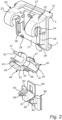
- the three components are illustrated separately from each other in figure 2 and will not be described in detail with reference to figure 2 .
- the ESL support body 20 is in the illustrated embodiment formed as an integrated part of the ESL holder 12.
- the holder 12 comprises a lower 2 and an upper 3 ESL holder designed to grip a corresponding structure along the upper and lower side of the ESL casing in a male/female configuration.
- the ESL support body could also be embodied as an integrated part of the ESL casing back side.
- the ESL support body 20, illustrated in perspective in figure 2 comprises a substantially flat member 21 extending in a plane substantially parallel to the back, and front side, of an ESL fitted in the ESL holder.
- the flat member is integrated with the ESL holder and has a height and width corresponding to the desired dimensions of the ESL holder to be able to fit the ELS in the ESL holder.
- the dimensions of the ESL holder and the support arrangement according to the invention are selected not to extend outside the ESL casing to be substantially hidden behind the ESL.
- two support hooks 22, 23 extend substantially parallel to each other in a transverse direction from said flat member 21 backwards.
- the two support hooks are arranged at a distance larger than the diameter of the elongated support rod 15 from each other.
- the two support hooks have the same shape and dimensions and the hooks are turned downwards to enclose a substantially circular interior 24 formed within the hooks and arranged at a distance from the flat member 21.
- the circular interior of the hook has a radius corresponding to the radius of the transverse member 16, i.e. the circular interior 24 has a radius larger than the radius of the transverse member 16.
- Each support hook has an opening 25 with a dimension, i.e. length, exceeding the double radius of the transverse member 16 to make it possible to fit the hooks on the transverse member.
- the openings are arranged facing downwards such that the ESL support body could be hanged on the transverse member from above.
- the arrangement furthermore comprises the angle selection element 40 that is turnably fitted to the support body 20.
- the angle selection element 40 comprises two substantially identical sleeve shaped elements 41 that are fitted within the circular interior of the respective support hook 22, 23.
- the sleeve shaped elements 41 are arranged coaxially to, and inside the circular interior of the support hooks 22, 23.
- the sleeve shaped elements 41 have an outer radius corresponding to the radius of the circular interior 24 of the support hooks 22, 23 and an inner radius corresponding to the radius of the transverse member 16.
- Each sleeve shaped element 41 has an internal radius corresponding to the radius of the transverse member 16 and a sleeve opening 42 with a dimension exceeding the double radius of the transverse member such that said sleeve opening 42 and said opening in the support hook 22, 23 could be aligned to make it possible to fit the support arrangement on the transverse member.
- the sleeve shaped elements 41 are connected by an intermediate member 43 extending between the two sleeve shaped elements.
- the intermediate member is intended to be arranged in the space formed between the two support hooks 22, 23 when the angle selection element is fitted to the support element.
- the intermediate member 43 comprises is two arms 44 extending from the sleeve shaped elements in substantially radial direction.
- Each arm 44 extend from one side of the sleeve opening 42 on the side of the respective sleeve shaped element 41 that is arranged towards the other sleeve shaped element 41.
- the two arms 44 are substantially identical with the same length in radial direction.
- the outer ends of the two arms 44 are connected by a substantially straight connecting element 45 extending substantially parallel to the flat member of the support element.
- the two arms together with the connecting element 45 constitute the protrusion 46 of the angle selection element.
- the angle selection element furthermore comprises one shoulder 47 for each sleeve shaped element.
- the shoulder is arranged around the sleeve shaped element adjacent to the arm in one end of the sleeve and has a number of cogs 48 arranged along the outer periphery of the shoulder.
- the third essential component of the arrangement according to the invention is the locking element 60.
- the locking element comprises a support plate 61 intended to be arranged adjacent to the flat member 21 of the support body.
- the support plate is slidably connected to the support body via guiding means 26.
- the guiding means are extending in substantially vertical direction along the flat member below the two support hooks to make it possible for the locking element to move in vertical direction between a first and second end position.
- the support plate 61 comprises an upper edge 62 that is facing the support hook 22, 23 when the different components of the arrangement are assembled and from the support plate close to the upper edge two locking arms 63 extend substantially transvers from the support plate at a distance from each other.
- the positions of the locking arms 63 are selected such that locking shoulders 64 in the outer end of the locking arms 63 will be able to cooperate with the cogs on the shoulders of the angle selection element 40.
- the locking element furthermore comprises a loop 65 extending from the upper edge 62 upwards.
- the loop 65 is intended to cooperate with securing means 27 on the support body 20 to maintain the locking element in the upper locking position.
- the loop 65 is pushed backwards from the flat member 21 and the locking means 27. Once the loop 65 released from the locking means the locking element 60 could be moved from the second locked position and returned to the first position.
- First the assembled arrangement is configured in the first starting position illustrated in figure 3A .
- the openings 25 of the support hooks 22, 23 are aligned with the sleeve openings 42 to open the interior of the sleeve shaped element and support hooks.
- the locking element is in the lower end position where the locking shoulders 64 are not in contact the cogs 48, and the protrusion is arranged adjacent to the flat member below the support hooks 22, 23.
- the ESL support arrangement is then attached to the elongated support member by fitting the ESL support arrangement to the transverse member 16. This is done by introducing the transverse member 16 into the two sleeve shaped elements 41 with the elongated support rod arranged in the space between the two support hooks 22, 23.
- the ESL holder and/or ESL is moved to the desired angular position by the operator, and the angle selection element 40 is turned from the starting position around the transverse member to the position where the protrusion 46, i.e. the surface of the connecting element 45, is in contact with the lower side of the elongated support rod 15 to provide a reliable support for the ESL holder / ESL in the selected angular position.
- the angle selection element is moved from the first position the sleeve shaped elements close the openings in the support hooks and lock the arrangement to the transverse element 16 of the support element.
- the arrangement is locked in the selected angular position by sliding the locking element 60 upwards to the locking position in which the locking shoulders 64, in the end of the locking arms 63, are fitted between adjacent cogs 48 on the angle selection element 40 to prevent that the angle selection element 40 is moved from the selected position.
- the steps above are conducted in opposite order, i.e. first the locking element 60 is moved downwards to disengage the locking shoulders 64 from the cogs 48 on the angle selection element 40. Once the locking element is moved, the angle selection element is turned away from the elongated support rod to the flat member of the support body such that the opening of the support hooks 22, 23 and the sleeve shaped elements are aligned and space formed within the sleeve shaped element opened to make it possible to dismount the ESL support from the transverse member.
- the arrangement according to the invention furthermore comprises an attachment means 70 for an additional flag that could be arranged below the ESL holder to make it possible to display additional information in combination with the information displayed on the ESL regarding the product.
- the attachment means are illustrated in figure 3D .
- the attachment means comprises two attachment shoulders 28 arranged on the backside of the flat member 21 of the support element along the lower edge of the flat member.
- the attachment shoulder 28 extend a distance from the flat member and are configured to cooperate with the support plate 61 of the locking element 60 to form two locking elements arranged in opposite ends of a slot 71 formed between the flat member 21 and the support plate 61.
- the attachment means 70 are intended to make it possible to attach a flag, or information display device, provided with a protrusion with a width corresponding to the distance between the two attachment shoulders 28 and two securing tabs with a width exceeding the distance between the two attachment shoulders 28. i.e. the width of the protrusion in transverse direction to the protrusion.
- the flag, or information display device is attached to the ESL holder by introducing the protrusion in the slot 71 such that the securing tabs are arranged above the attachment shoulders 28 and the flag or information display device secured to the ESL holder.
- FIG 4 An exploded view of a second embodiment of the arrangement 10' according to the invention is illustrated in figure 4 .
- This embodiment comprises the same essential parts as the embodiment described above but the different parts are modified to provide an even more robust and reliable fitting of the ESL to the support member 14.
- This embodiment is adapted to a support element with a support rod 15 and transverse member 16 with smaller radius.
- the arrangement 10' comprises the same three essential components, an ESL support body 20', an angle selection element 40' and a locking element 60'.
- the three components are illustrated separately from each other in figure 4 .
- the ESL support body 20' is also in the second embodiment formed as an integrated part of the ESL holder 12.
- the support body 20' is in this embodiment modified and each support hook 22', 23' comprises two substantially identical support hook elements 22a and 22b, and 23a and 23b arranged at a distance from each other.
- the support hook elements provided support along a longer distance of the transverse member 16 to provided further improved support of the ESL support body on the transverse member 16 of the support element 14 and reduce the risk that the ESL support arrangement is unintentionally removed from the transverse member 16.
- the distance between the support hook elements 22b and 23b arranged closest to the elongated support rod of the support member is reduced to provide a tighter fitting to the support element.
- the angle support element 40' is modified accordingly to correspond to the support element 20'and comprises two substantially identical sleeve shaped elements 41' that are fitted within the circular interior formed by the two support hook elements of the support hooks.
- the sleeve shaped elements 41' are connected by an intermediate member 43' extending between the two sleeve shaped elements.
- the intermediate member 43' comprises two arms 44' extending from the sleeve shaped elements.
- the two arms 44' are substantially identical with the same length in radial direction and the outer ends of the two arms 44' are connected by a connecting element 45' extending substantially parallel to the flat member of the support element.
- a semi-circular recess 49' intended to bear against the elongated support rod is formed.
- the angle selection element furthermore comprises one shoulder 47 for each sleeve shaped element.
- the shoulder is arranged around the sleeve shaped element adjacent to the arm in one end of the sleeve and has a number of cogs 48 arranged along the outer periphery of the shoulder.
- the locking element 60' is substantially identical to the previously described locking element but is modified to fit with the support element 40' and angle selection element 40'.
- the locking element 60' comprises: the support plate 61' with the upper edge 62', two locking arms 63' extend substantially transvers from the support plate at a distance from each other such that locking shoulders 64' in the outer end of the locking arms 63' cooperate with the cogs 48' on the angle selection element 40'.
- the locking element furthermore comprises the loop 65' extending from the upper edge to cooperate with securing means 27' on the support body 20 to maintain the locking element in the upper locking position as described above.
Landscapes
- Physics & Mathematics (AREA)
- General Physics & Mathematics (AREA)
- Engineering & Computer Science (AREA)
- Theoretical Computer Science (AREA)
- Supports Or Holders For Household Use (AREA)
- Display Racks (AREA)
Description
- The present invention relates to an arrangement for securing an electronic shelf label (ESL) to an elongated support element.
- In stores, for example supermarkets etc., electronic shelf labels, also named ESLs, are used for displaying information about the different products offered in the store. The information displayed could be the name, type of product, information regarding the product as well as the price for each of the products.
- The electronic shelf labels are communicating with a central control unit that makes it possible to frequently update, and change the information displayed on the labels which saves a considerable amount of time for the persons working in the store, especially if the number of different products sold in the store is high. As an example, a supermarket offers between 5000 and 20000 different products.
- Different types of systems are used to support the electronic shelf labels to make them easy for the customer to see, and to make it possible to restructure the different items offered for sale and the electronic shelf labels accordingly. One frequently used support element is an elongated rod extending from a shelf, a wall structure or a stand to make it possible to arrange the electronic shelf label closer to the customer. The rod could also be used as a hanger for items. The elongated rod is ended by substantially straight end element such that the elongated rod and end element will have a T-shape to make it possible the secure an ESL in the outer end of the support element.
- One example of an arrangement intended to support an ESL in the outer end of the described T-shaped rod is disclosed in document
FR3051587A1 - Further examples of arrangements intended to support an ESL on a T-shaped rod are described in
DE202012011261 U1 andJP2003233323 A - The present invention, defined in the appended claims, provides an arrangement for securing an electronic shelf label (ESL) to an elongated support element. The arrangement comprises:
- an ESL support body secured in an ESL casing, or an ESL holder, said support body comprises a substantially flat member extending in a plane substantially parallel to the ESL and two support hooks extending from said flat member, said support hooks each comprising a substantially circular interior with an internal radius corresponding to an radius of the transverse member, and an opening, intended to face downwards, exceeding the double radius of the transverse member such that the support hook is arrangeable around the transverse member;
- an angle selection element turnably connected to the support body to make it possible to select an angular position of the support body in relation to the elongated support element, said angle selection element comprises a protrusion intended to be in contact with the elongated support element when the support body is in the desired angular position; and
- a locking element slidably arranged along the flat member between a first position in which the angle selection element is turnable in relation to the support body around the transverse member, and a second position in which the angle selection element is locked in relation to the support body and the desired angular position of the support body maintained.
- The support arrangement according to the invention solves, or at least reduces the problems defined above since the protrusion of the angle selection element provides a reliable support of the ESL in the selected angle when arranged in mechanical contact with the lower side of the elongated support element and locked in the selected position by the locking element. The protrusion ensures that the selected angle of the ESL will remain even though the ESL is exposed to external forces that are directed to move the ESL from the selected and desired angular position around the transverse member. Furthermore, the arrangement is locked to the support element when the angle selection element is moved from the first to the second configuration.
- The angle selection element is turnable between a first position in which the opening of the two support hooks is open and the support body attachable to / detachable from the support element, and a second position in which the angular position of the support body in relation to the elongated support element is maintained. This ensures that the ESL is efficiently attached / detached from the support element.
- The angle selection element comprises at least one sleeve shaped element arranged coaxial to the circular interior of the support hooks and with an internal radius corresponding to the radius of the transverse member, said sleeve shaped element comprises an sleeve opening exceeding the double radius of the transverse member, wherein said sleeve opening and said opening in the support hook are aligned when the angle selection element is in the first position and non-aligned when the angle selection element is moved from the first position such that the transverse member is maintained in the support hook. This provides a robust support of the ESL since the ESL is locked to the transverse member of the support element as soon as the angle selection element is moved from the first assembly position until the angle selection element is returned to the first assembly position.
- The angle selection element comprises a number of cogs arranged around the sleeve shaped element, and the locking element comprises locking shoulders arranged to cooperate with the cogs on the angle selection element to lock the angle selection element in the selected angular position in relation to the support body. This provides a stable and reliable locking of angle selection element.
- In one embodiment of the arrangement, the ESL holder of the support body comprises an upper and a lower holder and the ESL is removably secured to the ESL holder. This embodiment is favourable since the same support arrangement could be used for different ESLs and the holder used even though the ESL needs to be replaced.
- In one embodiment of the arrangement, the support body comprises guiding means arranged to slidably support the locking element. This embodiment provides a reliable movement between the different positions of the locking element, and ensures that the locking element is maintained in the intended position in relation to the support body and the angle selection element.
- In one embodiment of the arrangement, the guiding means are extending along the flat element and the locking element slidable along a direction substantially parallel to the flat element of the support body.
- The different described embodiments of the invention could of course be combined in different ways without departing from the scope of the invention that will be described more in detail in the detailed description.
- Selected parts of different embodiments of the arrangement according to the invention are illustrated in the appended figures.
-
Figure 1 illustrates a perspective view of the arrangement according to the invention. -
Figure 2 illustrates an exploded view of the three essential components of the arrangement according to the invention. -
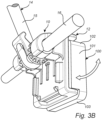
Figure 3A ,3B illustrates selected parts of the arrangement according to the invention. -
Figure 3C and3D illustrates the arrangement according to the invention in different configurations before, during and after the arrangement is arranged to support the ESL in the desired angle. -
Figure 4 illustrates an exploded view of a second embodiment of the arrangement according to the invention. - In
figure 1 thearrangement 10 according to the invention is illustrated in perspective. The arrangement is intended to be arranged on a back side of an electronic shelf label, i.e ESL, illustrated for example infigure 3A to 3D to attach the ESL to an elongated support element intended to extend from a shelf or wall structure in for example a store. In the embodiment of the arrangement illustrated infigure 1 , the arrangement is arranged on anESL holder 12 to which an ESL could be removably attached. A section of theelongated support element 14 is illustrated infigure 3A to 3D and comprises anelongated support rod 15 and atransverse element 16 arranged in the outer end of the elongated support rod to make it possible to provide a rigid and reliable support for the ESL. - The
elongated support element 14 comprises anelongated rod 15 extending from a forward edge of a shelf, from a wall structure or a stand to make it possible to arrange the electronic shelf label closer to the customer where it is easy to view. Theelongated rod 15 could also be used as a hanger for different items or packages offered for sale. The outer end of the elongated rod is ended by the substantially straighttransverse element 16 to provide sufficient support the ESL and facilitate the securing of the ESL to the support element, i.e. the elongated support member will have a T-shape in order to make it possible the secure the ESL in the outer end of the support element. Thetransverse element 16 has a substantially circular cross-section. - The ESL 100 comprises a
housing 101. The housing is substantially rectangular with an upper 102 andlower side 103 arranged parallel to each other, twoside surfaces 104, and a forward and back side. The forward side is not visible in the illustrations but is substantially flat and comprises a display area that is configured to display the desired information such as for example the price of a product. The back side is not visible in the illustrations but is substantially flat and facing the ESL holder. Thehousing 101 is for example made of a plastic material that provides the desired structural strength as well as the desired appearance of the ESL. In the forward side of the ESL, means for communication between the ESL and a central control system is arranged. In the illustrated ESL, this communication involves means for infra-red optical communication with an in the store centrally arranged control unit. Other alternatives for communication between the ESL and the central control system are however possible and the means for communication arranged in the ESL are then modified or adapted to the desired system for communication. In a further embodiment of an ESL, the means for communication could be arranged in the side surfaces or integrated within the casing as long as the desired contact between the ESL and the central control unit is achieved. - The
arrangement 10 according to the invention comprises three essential components, anESL support body 20, anangle selection element 40 and alocking element 60. The three components are illustrated separately from each other infigure 2 and will not be described in detail with reference tofigure 2 . - The
ESL support body 20 is in the illustrated embodiment formed as an integrated part of theESL holder 12. Theholder 12 comprises a lower 2 and an upper 3 ESL holder designed to grip a corresponding structure along the upper and lower side of the ESL casing in a male/female configuration. However, the ESL support body could also be embodied as an integrated part of the ESL casing back side. - The
ESL support body 20, illustrated in perspective infigure 2 , comprises a substantiallyflat member 21 extending in a plane substantially parallel to the back, and front side, of an ESL fitted in the ESL holder. In this embodiment, the flat member is integrated with the ESL holder and has a height and width corresponding to the desired dimensions of the ESL holder to be able to fit the ELS in the ESL holder. The dimensions of the ESL holder and the support arrangement according to the invention are selected not to extend outside the ESL casing to be substantially hidden behind the ESL. - From the flat member two support hooks 22, 23 extend substantially parallel to each other in a transverse direction from said
flat member 21 backwards. The two support hooks are arranged at a distance larger than the diameter of theelongated support rod 15 from each other. The two support hooks have the same shape and dimensions and the hooks are turned downwards to enclose a substantially circular interior 24 formed within the hooks and arranged at a distance from theflat member 21. The circular interior of the hook has a radius corresponding to the radius of thetransverse member 16, i.e. thecircular interior 24 has a radius larger than the radius of thetransverse member 16. Each support hook has anopening 25 with a dimension, i.e. length, exceeding the double radius of thetransverse member 16 to make it possible to fit the hooks on the transverse member. The openings are arranged facing downwards such that the ESL support body could be hanged on the transverse member from above. - The arrangement furthermore comprises the
angle selection element 40 that is turnably fitted to thesupport body 20. Theangle selection element 40 comprises two substantially identical sleeve shapedelements 41 that are fitted within the circular interior of therespective support hook elements 41 are arranged coaxially to, and inside the circular interior of the support hooks 22, 23. The sleeve shapedelements 41 have an outer radius corresponding to the radius of thecircular interior 24 of the support hooks 22, 23 and an inner radius corresponding to the radius of thetransverse member 16. - Each sleeve shaped
element 41 has an internal radius corresponding to the radius of thetransverse member 16 and asleeve opening 42 with a dimension exceeding the double radius of the transverse member such that saidsleeve opening 42 and said opening in thesupport hook - The sleeve shaped
elements 41 are connected by anintermediate member 43 extending between the two sleeve shaped elements. The intermediate member is intended to be arranged in the space formed between the two support hooks 22, 23 when the angle selection element is fitted to the support element. - The
intermediate member 43 comprises is twoarms 44 extending from the sleeve shaped elements in substantially radial direction. Eacharm 44 extend from one side of thesleeve opening 42 on the side of the respective sleeve shapedelement 41 that is arranged towards the other sleeve shapedelement 41. The twoarms 44 are substantially identical with the same length in radial direction. The outer ends of the twoarms 44 are connected by a substantially straight connectingelement 45 extending substantially parallel to the flat member of the support element. The two arms together with the connectingelement 45 constitute theprotrusion 46 of the angle selection element. - The angle selection element furthermore comprises one
shoulder 47 for each sleeve shaped element. The shoulder is arranged around the sleeve shaped element adjacent to the arm in one end of the sleeve and has a number ofcogs 48 arranged along the outer periphery of the shoulder. - The third essential component of the arrangement according to the invention is the locking
element 60. The locking element comprises asupport plate 61 intended to be arranged adjacent to theflat member 21 of the support body. The support plate is slidably connected to the support body via guidingmeans 26. The guiding means are extending in substantially vertical direction along the flat member below the two support hooks to make it possible for the locking element to move in vertical direction between a first and second end position. Thesupport plate 61 comprises anupper edge 62 that is facing thesupport hook arms 63 extend substantially transvers from the support plate at a distance from each other. The positions of the lockingarms 63 are selected such that locking shoulders 64 in the outer end of the lockingarms 63 will be able to cooperate with the cogs on the shoulders of theangle selection element 40. - The locking element furthermore comprises a
loop 65 extending from theupper edge 62 upwards. Theloop 65 is intended to cooperate with securing means 27 on thesupport body 20 to maintain the locking element in the upper locking position. To release the loop from the locking means 27, theloop 65 is pushed backwards from theflat member 21 and the locking means 27. Once theloop 65 released from the locking means the lockingelement 60 could be moved from the second locked position and returned to the first position. - The method for using the arrangement according to the invention will now be described with reference to
Figure 3A ,3B ,3C and3D illustrating different configurations of the arrangement before, during and after the arrangement is arranged to the support the ESL in the desired angle. Infigure 3A and3B the locking element is not illustrated in its assembled state to illustrate the different components and features more clearly. However, the different components of the arrangement are normally assembled before fitting to the support element. - First the assembled arrangement is configured in the first starting position illustrated in
figure 3A . In the first position, theopenings 25 of the support hooks 22, 23 are aligned with thesleeve openings 42 to open the interior of the sleeve shaped element and support hooks. The locking element is in the lower end position where the locking shoulders 64 are not in contact thecogs 48, and the protrusion is arranged adjacent to the flat member below the support hooks 22, 23. - The ESL support arrangement is then attached to the elongated support member by fitting the ESL support arrangement to the
transverse member 16. This is done by introducing thetransverse member 16 into the two sleeve shapedelements 41 with the elongated support rod arranged in the space between the two support hooks 22, 23. - Once the first step is completed the ESL holder and/or ESL is moved to the desired angular position by the operator, and the
angle selection element 40 is turned from the starting position around the transverse member to the position where theprotrusion 46, i.e. the surface of the connectingelement 45, is in contact with the lower side of theelongated support rod 15 to provide a reliable support for the ESL holder / ESL in the selected angular position. Simultaneously as the angle selection element is moved from the first position the sleeve shaped elements close the openings in the support hooks and lock the arrangement to thetransverse element 16 of the support element. - In the final step, illustrated in
figure 3C and3D , the arrangement is locked in the selected angular position by sliding the lockingelement 60 upwards to the locking position in which the locking shoulders 64, in the end of the lockingarms 63, are fitted betweenadjacent cogs 48 on theangle selection element 40 to prevent that theangle selection element 40 is moved from the selected position. - To dismount the ESL support arrangement or ESL from the elongated support element the steps above are conducted in opposite order, i.e. first the locking
element 60 is moved downwards to disengage the locking shoulders 64 from thecogs 48 on theangle selection element 40. Once the locking element is moved, the angle selection element is turned away from the elongated support rod to the flat member of the support body such that the opening of the support hooks 22, 23 and the sleeve shaped elements are aligned and space formed within the sleeve shaped element opened to make it possible to dismount the ESL support from the transverse member. - The arrangement according to the invention furthermore comprises an attachment means 70 for an additional flag that could be arranged below the ESL holder to make it possible to display additional information in combination with the information displayed on the ESL regarding the product. The attachment means are illustrated in
figure 3D . The attachment means comprises twoattachment shoulders 28 arranged on the backside of theflat member 21 of the support element along the lower edge of the flat member. Theattachment shoulder 28 extend a distance from the flat member and are configured to cooperate with thesupport plate 61 of the lockingelement 60 to form two locking elements arranged in opposite ends of aslot 71 formed between theflat member 21 and thesupport plate 61. The attachment means 70 are intended to make it possible to attach a flag, or information display device, provided with a protrusion with a width corresponding to the distance between the twoattachment shoulders 28 and two securing tabs with a width exceeding the distance between the two attachment shoulders 28. i.e. the width of the protrusion in transverse direction to the protrusion. The flag, or information display device, is attached to the ESL holder by introducing the protrusion in theslot 71 such that the securing tabs are arranged above the attachment shoulders 28 and the flag or information display device secured to the ESL holder. - An exploded view of a second embodiment of the arrangement 10' according to the invention is illustrated in
figure 4 . This embodiment comprises the same essential parts as the embodiment described above but the different parts are modified to provide an even more robust and reliable fitting of the ESL to thesupport member 14. This embodiment is adapted to a support element with asupport rod 15 andtransverse member 16 with smaller radius. - The arrangement 10' according to the invention comprises the same three essential components, an ESL support body 20', an angle selection element 40' and a locking element 60'. The three components are illustrated separately from each other in
figure 4 . - The ESL support body 20' is also in the second embodiment formed as an integrated part of the
ESL holder 12. The support body 20' is in this embodiment modified and each support hook 22', 23' comprises two substantially identicalsupport hook elements transverse member 16 to provided further improved support of the ESL support body on thetransverse member 16 of thesupport element 14 and reduce the risk that the ESL support arrangement is unintentionally removed from thetransverse member 16. Furthermore, the distance between thesupport hook elements - The angle support element 40' is modified accordingly to correspond to the support element 20'and comprises two substantially identical sleeve shaped elements 41' that are fitted within the circular interior formed by the two support hook elements of the support hooks. The sleeve shaped elements 41' are connected by an intermediate member 43' extending between the two sleeve shaped elements. The intermediate member 43' comprises two arms 44' extending from the sleeve shaped elements. The two arms 44' are substantially identical with the same length in radial direction and the outer ends of the two arms 44' are connected by a connecting element 45' extending substantially parallel to the flat member of the support element. In the centre of the connecting element 45', a semi-circular recess 49' intended to bear against the elongated support rod is formed. The two arms together with the connecting element 45' constitute the protrusion 46'. The angle selection element furthermore comprises one
shoulder 47 for each sleeve shaped element. The shoulder is arranged around the sleeve shaped element adjacent to the arm in one end of the sleeve and has a number ofcogs 48 arranged along the outer periphery of the shoulder. - The locking element 60' is substantially identical to the previously described locking element but is modified to fit with the support element 40' and angle selection element 40'. The locking element 60' comprises: the support plate 61' with the upper edge 62', two locking arms 63' extend substantially transvers from the support plate at a distance from each other such that locking shoulders 64' in the outer end of the locking arms 63' cooperate with the cogs 48' on the angle selection element 40'. The locking element furthermore comprises the loop 65' extending from the upper edge to cooperate with securing means 27' on the
support body 20 to maintain the locking element in the upper locking position as described above. - While the invention has been illustrated and described in detail in the drawings and foregoing description, such illustration and description are to be considered illustrative or exemplary and not restrictive; the invention is not limited to the disclosed embodiments. The skilled person understands that many modifications, variations and alterations are conceivable within the scope as defined in the appended claims.
- Additionally, variations to the disclosed embodiments can be understood and effected by those skilled in the art in practicing the claimed invention, from a study of the drawings, the disclosure, and the appended claims. In the claims, the word "comprising" does not exclude other elements or steps, and the indefinite article "a" or "an" does not exclude a plurality. The mere fact that certain measures are recited in mutually different dependent claims does not indicate that a combination of these measures cannot be used to advantage. Any reference signs in the claims should not be construed as limiting the scope of the claims..
Claims (4)
- Arrangement (10; 10') for securing an electronic shelf label (ESL) (100) to an elongated support element (14) with a transverse member (16) with substantially circular cross section such that the support element (14) has a T-shaped outer end, said arrangement comprising:an ESL support body (20; 20') integrated with an ESL casing or an ESL holder (12), said support body comprises a substantially flat member (21; 21') extending in a plane substantially parallel to the ESL and two support hooks (22, 23; 22', 23') extending from said flat member, said support hooks each comprising a substantially circular interior with an internal radius corresponding to an radius of the transverse member (16), and an opening (25; 25'), intended to face downwards, exceeding the double radius of the transverse member such that the support hook is arrangeable around the transverse member;whereby the arrangement further comprises an angle selection element (40; 40') turnably connected to the support body (20; 20') to make it possible to select an angular position of the support body (20; 20') in relation to the elongated support element (14), said angle selection element comprises a protrusion (46; 46') intended to be in contact with the elongated support element (14) when the support body is in the desired angular position, whereinthe angle selection element is turnable between a first position in which the openings (25; 25') of the two support hooks (22, 23; 22',23') are open and the support body (20; 20') attachable to / detachable from the support element (14), and a second position in which the angular position of the support body (20; 20') in relation to the elongated support element (14) is maintained, characterized in thatthe angle selection element (40; 40') comprises at least one sleeve shaped element (41; 41') arranged coaxial to the circular interior (24; 24') of the support hooks (22, 23; 22', 23') and with an internal radius corresponding to the radius of the transverse member (16), said sleeve shaped element (41) comprises an sleeve opening (42; 42') exceeding the double radius of the transverse member (16), wherein said sleeve opening and said opening in the support hook are aligned when the angle selection element is in the first position and non-aligned when the angle selection element is moved from the first position such that the transverse member is maintained in the support hook (22, 23; 22', 23'); anda locking element (60; 60') slidably arranged along the flat member (21; 21') between a first position in which the angle selection element (40; 40') is turnable in relation to the support body (20; 20') around the transverse member, and a second position in which the angle selection element (40; 40') is locked in relation to the support body (20; 20') and the desired angular position of the support body (20; 20') maintained, and whereinthe angle selection element (40; 40') furthermore comprises a number of cogs (48) arranged around the sleeve shaped element (41), and the locking element (60; 60') comprises locking shoulders (64) arranged to cooperate with the cogs (48) on the angle selection element (40) to lock the angle selection element (40) in the selected angular position in relation to the support body (20; 20').
- Arrangement (10; 10') according to anyone of the previous claims, wherein the ESL holder of the support body (20; 20') comprises an upper (3) and a lower holder (2) and the ESL is removably secured to the ESL holder.
- Arrangement (10; 10') according to anyone or the previous claims, wherein the support body (20; 20') comprises guiding means (26;, 26') arranged to slidably support the locking element (60; 60').
- Arrangement (10; 10') according to claim 3, wherein the guiding means (26; , 26') are extending along the flat member (21; 21') and the locking element (60; 60') is slidable along a direction substantially parallel to the flat member (21; 21')of the support body (20; 20').
Applications Claiming Priority (2)
| Application Number | Priority Date | Filing Date | Title |
|---|---|---|---|
| SE1851436 | 2018-11-19 | ||
| PCT/SE2019/051163 WO2020106206A1 (en) | 2018-11-19 | 2019-11-15 | Arrangement for supporting an electronic shelf label in a desired angle |
Publications (4)
| Publication Number | Publication Date |
|---|---|
| EP3884482A1 EP3884482A1 (en) | 2021-09-29 |
| EP3884482A4 EP3884482A4 (en) | 2022-09-14 |
| EP3884482B1 true EP3884482B1 (en) | 2024-12-25 |
| EP3884482C0 EP3884482C0 (en) | 2024-12-25 |
Family
ID=70774099
Family Applications (1)
| Application Number | Title | Priority Date | Filing Date |
|---|---|---|---|
| EP19887316.8A Active EP3884482B1 (en) | 2018-11-19 | 2019-11-15 | Arrangement for supporting an electronic shelf label in a desired angle |
Country Status (2)
| Country | Link |
|---|---|
| EP (1) | EP3884482B1 (en) |
| WO (1) | WO2020106206A1 (en) |
Cited By (1)
| Publication number | Priority date | Publication date | Assignee | Title |
|---|---|---|---|---|
| US12700332B2 (en) | 2023-09-15 | 2026-08-04 | Fasteners For Retail, Inc. | Electronic shelf label holder |
Families Citing this family (1)
| Publication number | Priority date | Publication date | Assignee | Title |
|---|---|---|---|---|
| CN116420181B (en) * | 2020-11-03 | 2024-01-12 | 唐山圣因海洋科技有限公司 | Storage goods shelves label device |
Family Cites Families (5)
| Publication number | Priority date | Publication date | Assignee | Title |
|---|---|---|---|---|
| SE513109C2 (en) * | 1998-11-06 | 2000-07-10 | Hl Display Ab | Angle adjustable label holder for product exposure stands |
| JP3711451B2 (en) * | 2002-02-12 | 2005-11-02 | 日研工業株式会社 | Display holder |
| FR2861884B1 (en) * | 2003-10-31 | 2006-02-24 | Joalpe Ind De Expositores Sa | DISPLAY DEVICE, IN PARTICULAR FOR ELECTRONIC PRICE DISPLAY |
| DE202012011261U1 (en) * | 2012-11-23 | 2012-12-06 | Oechsle Display Systeme Gmbh | Carrying device for a display device |
| EP2770492B1 (en) * | 2013-02-22 | 2017-08-23 | Hl Display Ab | A label holder |
-
2019
- 2019-11-15 EP EP19887316.8A patent/EP3884482B1/en active Active
- 2019-11-15 WO PCT/SE2019/051163 patent/WO2020106206A1/en not_active Ceased
Cited By (1)
| Publication number | Priority date | Publication date | Assignee | Title |
|---|---|---|---|---|
| US12700332B2 (en) | 2023-09-15 | 2026-08-04 | Fasteners For Retail, Inc. | Electronic shelf label holder |
Also Published As
| Publication number | Publication date |
|---|---|
| EP3884482A1 (en) | 2021-09-29 |
| EP3884482C0 (en) | 2024-12-25 |
| WO2020106206A1 (en) | 2020-05-28 |
| EP3884482A4 (en) | 2022-09-14 |
Similar Documents
| Publication | Publication Date | Title |
|---|---|---|
| US10662672B2 (en) | Locking device for product display hooks, showcases, cabinets, fixtures, and casework | |
| EP1735662B1 (en) | Adapter for attaching an electronic shelf label to a blister hook | |
| CN201641249U (en) | adjustable display unit | |
| US8127946B2 (en) | Eyewear display system | |
| US20050029205A1 (en) | Merchandise display hook | |
| US9993094B1 (en) | Rotary display hook | |
| US10156088B2 (en) | Locking device for product display hooks, showcases, cabinets, fixtures, and casework | |
| EP3884482A1 (en) | Arrangement for supporting an electronic shelf label in a desired angle | |
| US2208152A (en) | Hanger | |
| AU2007203482A1 (en) | Card product display system | |
| US8567220B1 (en) | Magnetic lock assembly | |
| US20160367049A1 (en) | Extendable display hanger | |
| US20160203740A1 (en) | Signage systems | |
| US2008180A (en) | Display stand | |
| US9681760B1 (en) | Hang tab with multiple positions | |
| EP4066233B1 (en) | Support arrangement for a unit used within a retail environment | |
| US20150152670A1 (en) | Hook lock for securing merchandise on product display hooks | |
| US7185794B2 (en) | Garment security hanger and display system | |
| US20060278590A1 (en) | Display device particularly for electronic display of prices | |
| KR101791191B1 (en) | Hook unit for hanging goods | |
| WO2021215994A1 (en) | Arrangement for attaching an electronic label to a peghook and a method for arranging an object to such an arrangement | |
| US20030192924A1 (en) | System for frontal display of objects | |
| EP2708163B1 (en) | Device for hanging up a display panel | |
| EP2044863A1 (en) | Device and method for displaying objects | |
| KR20200000808U (en) | The display rack |
Legal Events
| Date | Code | Title | Description |
|---|---|---|---|
| STAA | Information on the status of an ep patent application or granted ep patent |
Free format text: STATUS: THE INTERNATIONAL PUBLICATION HAS BEEN MADE |
|
| PUAI | Public reference made under article 153(3) epc to a published international application that has entered the european phase |
Free format text: ORIGINAL CODE: 0009012 |
|
| STAA | Information on the status of an ep patent application or granted ep patent |
Free format text: STATUS: REQUEST FOR EXAMINATION WAS MADE |
|
| 17P | Request for examination filed |
Effective date: 20210614 |
|
| AK | Designated contracting states |
Kind code of ref document: A1 Designated state(s): AL AT BE BG CH CY CZ DE DK EE ES FI FR GB GR HR HU IE IS IT LI LT LU LV MC MK MT NL NO PL PT RO RS SE SI SK SM TR |
|
| DAV | Request for validation of the european patent (deleted) | ||
| DAX | Request for extension of the european patent (deleted) | ||
| A4 | Supplementary search report drawn up and despatched |
Effective date: 20220816 |
|
| RIC1 | Information provided on ipc code assigned before grant |
Ipc: G09F 3/20 20060101AFI20220809BHEP |
|
| GRAP | Despatch of communication of intention to grant a patent |
Free format text: ORIGINAL CODE: EPIDOSNIGR1 |
|
| STAA | Information on the status of an ep patent application or granted ep patent |
Free format text: STATUS: GRANT OF PATENT IS INTENDED |
|
| INTG | Intention to grant announced |
Effective date: 20240730 |
|
| GRAS | Grant fee paid |
Free format text: ORIGINAL CODE: EPIDOSNIGR3 |
|
| GRAA | (expected) grant |
Free format text: ORIGINAL CODE: 0009210 |
|
| STAA | Information on the status of an ep patent application or granted ep patent |
Free format text: STATUS: THE PATENT HAS BEEN GRANTED |
|
| AK | Designated contracting states |
Kind code of ref document: B1 Designated state(s): AL AT BE BG CH CY CZ DE DK EE ES FI FR GB GR HR HU IE IS IT LI LT LU LV MC MK MT NL NO PL PT RO RS SE SI SK SM TR |
|
| REG | Reference to a national code |
Ref country code: GB Ref legal event code: FG4D |
|
| REG | Reference to a national code |
Ref country code: CH Ref legal event code: EP |
|
| REG | Reference to a national code |
Ref country code: DE Ref legal event code: R096 Ref document number: 602019064087 Country of ref document: DE |
|
| REG | Reference to a national code |
Ref country code: IE Ref legal event code: FG4D |
|
| U01 | Request for unitary effect filed |
Effective date: 20250113 |
|
| U07 | Unitary effect registered |
Designated state(s): AT BE BG DE DK EE FI FR IT LT LU LV MT NL PT RO SE SI Effective date: 20250117 |
|
| PG25 | Lapsed in a contracting state [announced via postgrant information from national office to epo] |
Ref country code: HR Free format text: LAPSE BECAUSE OF FAILURE TO SUBMIT A TRANSLATION OF THE DESCRIPTION OR TO PAY THE FEE WITHIN THE PRESCRIBED TIME-LIMIT Effective date: 20241225 |
|
| PG25 | Lapsed in a contracting state [announced via postgrant information from national office to epo] |
Ref country code: NO Free format text: LAPSE BECAUSE OF FAILURE TO SUBMIT A TRANSLATION OF THE DESCRIPTION OR TO PAY THE FEE WITHIN THE PRESCRIBED TIME-LIMIT Effective date: 20250325 |
|
| PG25 | Lapsed in a contracting state [announced via postgrant information from national office to epo] |
Ref country code: GR Free format text: LAPSE BECAUSE OF FAILURE TO SUBMIT A TRANSLATION OF THE DESCRIPTION OR TO PAY THE FEE WITHIN THE PRESCRIBED TIME-LIMIT Effective date: 20250326 |
|
| PG25 | Lapsed in a contracting state [announced via postgrant information from national office to epo] |
Ref country code: RS Free format text: LAPSE BECAUSE OF FAILURE TO SUBMIT A TRANSLATION OF THE DESCRIPTION OR TO PAY THE FEE WITHIN THE PRESCRIBED TIME-LIMIT Effective date: 20250325 |
|
| PG25 | Lapsed in a contracting state [announced via postgrant information from national office to epo] |
Ref country code: SM Free format text: LAPSE BECAUSE OF FAILURE TO SUBMIT A TRANSLATION OF THE DESCRIPTION OR TO PAY THE FEE WITHIN THE PRESCRIBED TIME-LIMIT Effective date: 20241225 |
|
| PG25 | Lapsed in a contracting state [announced via postgrant information from national office to epo] |
Ref country code: PL Free format text: LAPSE BECAUSE OF FAILURE TO SUBMIT A TRANSLATION OF THE DESCRIPTION OR TO PAY THE FEE WITHIN THE PRESCRIBED TIME-LIMIT Effective date: 20241225 |
|
| PG25 | Lapsed in a contracting state [announced via postgrant information from national office to epo] |
Ref country code: ES Free format text: LAPSE BECAUSE OF FAILURE TO SUBMIT A TRANSLATION OF THE DESCRIPTION OR TO PAY THE FEE WITHIN THE PRESCRIBED TIME-LIMIT Effective date: 20241225 |
|
| PG25 | Lapsed in a contracting state [announced via postgrant information from national office to epo] |
Ref country code: IS Free format text: LAPSE BECAUSE OF FAILURE TO SUBMIT A TRANSLATION OF THE DESCRIPTION OR TO PAY THE FEE WITHIN THE PRESCRIBED TIME-LIMIT Effective date: 20250425 |
|
| PG25 | Lapsed in a contracting state [announced via postgrant information from national office to epo] |
Ref country code: SK Free format text: LAPSE BECAUSE OF FAILURE TO SUBMIT A TRANSLATION OF THE DESCRIPTION OR TO PAY THE FEE WITHIN THE PRESCRIBED TIME-LIMIT Effective date: 20241225 |
|
| PG25 | Lapsed in a contracting state [announced via postgrant information from national office to epo] |
Ref country code: CZ Free format text: LAPSE BECAUSE OF FAILURE TO SUBMIT A TRANSLATION OF THE DESCRIPTION OR TO PAY THE FEE WITHIN THE PRESCRIBED TIME-LIMIT Effective date: 20241225 |
|
| PLBE | No opposition filed within time limit |
Free format text: ORIGINAL CODE: 0009261 |
|
| STAA | Information on the status of an ep patent application or granted ep patent |
Free format text: STATUS: NO OPPOSITION FILED WITHIN TIME LIMIT |
|
| REG | Reference to a national code |
Ref country code: CH Ref legal event code: L10 Free format text: ST27 STATUS EVENT CODE: U-0-0-L10-L00 (AS PROVIDED BY THE NATIONAL OFFICE) Effective date: 20251105 |
|
| U20 | Renewal fee for the european patent with unitary effect paid |
Year of fee payment: 7 Effective date: 20251016 |
|
| 26N | No opposition filed |
Effective date: 20250926 |
|
| PGFP | Annual fee paid to national office [announced via postgrant information from national office to epo] |
Ref country code: GB Payment date: 20251016 Year of fee payment: 7 |
|
| REG | Reference to a national code |
Ref country code: CH Ref legal event code: H13 Free format text: ST27 STATUS EVENT CODE: U-0-0-H10-H13 (AS PROVIDED BY THE NATIONAL OFFICE) Effective date: 20260623 |
|
| PG25 | Lapsed in a contracting state [announced via postgrant information from national office to epo] |
Ref country code: MC Free format text: LAPSE BECAUSE OF FAILURE TO SUBMIT A TRANSLATION OF THE DESCRIPTION OR TO PAY THE FEE WITHIN THE PRESCRIBED TIME-LIMIT Effective date: 20241225 |
|
| PG25 | Lapsed in a contracting state [announced via postgrant information from national office to epo] |
Ref country code: CH Free format text: LAPSE BECAUSE OF NON-PAYMENT OF DUE FEES Effective date: 20251130 |