EP3884473B1 - Signalling duress - Google Patents
Signalling duress Download PDFInfo
- Publication number
- EP3884473B1 EP3884473B1 EP19806196.2A EP19806196A EP3884473B1 EP 3884473 B1 EP3884473 B1 EP 3884473B1 EP 19806196 A EP19806196 A EP 19806196A EP 3884473 B1 EP3884473 B1 EP 3884473B1
- Authority
- EP
- European Patent Office
- Prior art keywords
- duress
- user
- key device
- wireless communication
- communication channel
- Prior art date
- Legal status (The legal status is an assumption and is not a legal conclusion. Google has not performed a legal analysis and makes no representation as to the accuracy of the status listed.)
- Active
Links
Images


Classifications
-
- H—ELECTRICITY
- H04—ELECTRIC COMMUNICATION TECHNIQUE
- H04W—WIRELESS COMMUNICATION NETWORKS
- H04W76/00—Connection management
- H04W76/10—Connection setup
-
- G—PHYSICS
- G07—CHECKING-DEVICES
- G07C—TIME OR ATTENDANCE REGISTERS; REGISTERING OR INDICATING THE WORKING OF MACHINES; GENERATING RANDOM NUMBERS; VOTING OR LOTTERY APPARATUS; ARRANGEMENTS, SYSTEMS OR APPARATUS FOR CHECKING NOT PROVIDED FOR ELSEWHERE
- G07C9/00—Individual registration on entry or exit
- G07C9/00174—Electronically operated locks; Circuits therefor; Nonmechanical keys therefor, e.g. passive or active electrical keys or other data carriers without mechanical keys
- G07C9/00309—Electronically operated locks; Circuits therefor; Nonmechanical keys therefor, e.g. passive or active electrical keys or other data carriers without mechanical keys operated with bidirectional data transmission between data carrier and locks
-
- G—PHYSICS
- G08—SIGNALLING
- G08B—SIGNALLING SYSTEMS, e.g. PERSONAL CALLING SYSTEMS; ORDER TELEGRAPHS; ALARM SYSTEMS
- G08B21/00—Alarms responsive to a single specified undesired or abnormal condition and not otherwise provided for
- G08B21/02—Alarms for ensuring the safety of persons
- G08B21/0202—Child monitoring systems using a transmitter-receiver system carried by the parent and the child
- G08B21/0277—Communication between units on a local network, e.g. Bluetooth®, piconet, Zigbee®, Wireless Personal Area Networks [WPAN]
-
- G—PHYSICS
- G08—SIGNALLING
- G08B—SIGNALLING SYSTEMS, e.g. PERSONAL CALLING SYSTEMS; ORDER TELEGRAPHS; ALARM SYSTEMS
- G08B25/00—Alarm systems in which the location of the alarm condition is signalled to a central station, e.g. fire or police telegraphic systems
- G08B25/01—Alarm systems in which the location of the alarm condition is signalled to a central station, e.g. fire or police telegraphic systems characterised by the transmission medium
- G08B25/016—Personal emergency signalling and security systems
-
- G—PHYSICS
- G08—SIGNALLING
- G08B—SIGNALLING SYSTEMS, e.g. PERSONAL CALLING SYSTEMS; ORDER TELEGRAPHS; ALARM SYSTEMS
- G08B25/00—Alarm systems in which the location of the alarm condition is signalled to a central station, e.g. fire or police telegraphic systems
- G08B25/01—Alarm systems in which the location of the alarm condition is signalled to a central station, e.g. fire or police telegraphic systems characterised by the transmission medium
- G08B25/10—Alarm systems in which the location of the alarm condition is signalled to a central station, e.g. fire or police telegraphic systems characterised by the transmission medium using wireless transmission systems
-
- H—ELECTRICITY
- H04—ELECTRIC COMMUNICATION TECHNIQUE
- H04W—WIRELESS COMMUNICATION NETWORKS
- H04W4/00—Services specially adapted for wireless communication networks; Facilities therefor
- H04W4/20—Services signaling; Auxiliary data signalling, i.e. transmitting data via a non-traffic channel
-
- G—PHYSICS
- G07—CHECKING-DEVICES
- G07C—TIME OR ATTENDANCE REGISTERS; REGISTERING OR INDICATING THE WORKING OF MACHINES; GENERATING RANDOM NUMBERS; VOTING OR LOTTERY APPARATUS; ARRANGEMENTS, SYSTEMS OR APPARATUS FOR CHECKING NOT PROVIDED FOR ELSEWHERE
- G07C9/00—Individual registration on entry or exit
- G07C9/00174—Electronically operated locks; Circuits therefor; Nonmechanical keys therefor, e.g. passive or active electrical keys or other data carriers without mechanical keys
- G07C9/00309—Electronically operated locks; Circuits therefor; Nonmechanical keys therefor, e.g. passive or active electrical keys or other data carriers without mechanical keys operated with bidirectional data transmission between data carrier and locks
- G07C2009/00507—Electronically operated locks; Circuits therefor; Nonmechanical keys therefor, e.g. passive or active electrical keys or other data carriers without mechanical keys operated with bidirectional data transmission between data carrier and locks keyless data carrier having more than one function
Definitions
- the invention relates to a key device, methods, computer programs and computer program products for signalling duress.
- Lock devices and key devices are evolving from the traditional pure mechanical locks. These days, there are wireless interfaces for electronic lock devices, e.g. by interacting with a key device. For instance, Radio Frequency Identification (RFID), Bluetooth Low Energy (BLE) etc. can be used for the communication between lock device and key device.
- RFID Radio Frequency Identification
- BLE Bluetooth Low Energy
- US 2013/091561 A1 discloses executing commands provided during user authentication.
- EP 2 262 292 A2 discloses a mobile communications device with security features.
- EP 1 971 172 A1 discloses enhanced handling of duress situations.
- CN 104 100 169 A discloses coercion-against alarm method, coercion-against alarm device and system using coercion-against alarm device.
- US 2018/122219 A1 discloses invisible indication of duress via a wearable.
- the step of determining that a user is under distress may comprise determining that the user is under distress unless a user input indicating non-distress is detected.
- the step of exiting the wait state and establishing a wireless communication channel may be triggered when the key device comes into wireless communication range with the lock device.
- the step of determining that a user is under duress may comprise detecting a predetermined movement pattern using an accelerometer in the key device.
- the step of determining that a user is under duress may comprise detecting a user interface interaction by the key device.
- the step of generating the duress signal may comprise setting a duress indicator in an access control message.
- a key device for supporting duress signalling according to claim 7.
- the instructions to determine that a user is under distress may comprise instructions that, when executed by the processor, cause the key device to determine that the user is under distress unless a user input indicating non-distress is detected.
- the key device may further comprise instructions that, when executed by the processor, cause the key device to trigger the instructions to exit the wait state and establish a wireless communication channel when the key device comes into wireless communication range with the lock device.
- the instructions to determine that a user is under duress may comprise instructions that, when executed by the processor, cause the key device to detect a predetermined movement pattern using an accelerometer in the key device.
- the instructions to determine that a user is under duress may comprise instructions that, when executed by the processor, cause the key device to detect a user interface interaction by the key device.
- the instructions to generate the duress signal may comprise instructions that, when executed by the processor, cause the key device to set a duress indicator in an access control message.
- a computer program product comprising a computer program according to the third aspect and a computer readable means on which the computer program is stored.
- Embodiments presented herein are based on using a communication channel intended for access control communication also for signalling a duress situation.
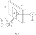
- Fig 1 is a schematic diagram showing an environment in which embodiments presented herein can be applied.
- Access to a physical space 16 is restricted by an openable physical barrier 15, which is selectively unlockable.
- the barrier 15 stands between the restricted physical space 16 on the inside of the barrier 15 and an accessible physical space 14 on the outside of the barrier 15.
- the accessible physical space 14 can be a restricted physical space in itself, but in relation to this particular barrier 15, the accessible physical space 14 is accessible.
- the restricted physical space 16 is inside the barrier 15 and the accessible physical space 14 is outside the physical barrier 15.
- a lock device 1 is provided.
- the lock device 1 is controllable to be set in an unlocked state or locked state.
- the lock device 1 communicates with a key device 2 over a wireless communication channel 4.
- the key device 2 is any suitable device portable by a user and which can be used for authentication over the wireless communication channel 4.
- the key device 2 is typically carried or worn by the user 7 and may be implemented as a mobile phone, a smartphone, a key fob, wearable device, smart phone case, etc.
- any suitable wireless interface e.g. using Bluetooth or Bluetooth Low Energy (BLE), ZigBee, any of the IEEE 802.11x standards (also known as WiFi), etc.
- BLE Bluetooth or Bluetooth Low Energy
- ZigBee any of the IEEE 802.11x standards
- WiFi also known as WiFi
- the lock device 1 grants or denies access.
- the communication between the key device 2 and the lock device 1 can be exploited for also communicating a duress signal.
- the lock device 1 can also communicate with an external server 8 using a communication network 6.
- the communication network can e.g. form part of the Internet and/or a cellular communication network.
- the lock device 1 When access is granted, the lock device 1 is set in an unlocked state. When the lock device 1 is in an unlocked state, the barrier 15 can be opened and when the lock device 1 is in a locked state, the barrier 15 cannot be opened. In this way, access to the inside 16 of the barrier 15 is controlled by the lock device 1. It is to be noted that the lock device 1 can be mounted in a surrounding structure 17 (e.g. wall) by the physical barrier 15 (as shown) or in the physical barrier 15 (not shown).
- a surrounding structure 17 e.g. wall
- the user 7 is said to be under duress. For instance, the user 7 could be threatened by an attacker 3 to gain access to the restricted physical space 16. A problem is then how the user 7 could signal this duress while keeping safe. This is solved according to the embodiments of the method described below.
- Fig 2 is a flow chart illustrating embodiments of methods for supporting duress signalling, performed in the key device of Fig 1 .
- the key device determines that a user is under duress.
- the user is under determined to be under distress unless a user input indicating non-distress is detected.
- duress is then the default situation and the user needs to perform a certain action to deactivate the duress state. In this way, if the user does not deactivate the duress, duress is assumed and appropriate further measures are taken (e.g. alarming security personnel). With this embodiment, no special signalling is needed for duress (other than the absence of duress deactivation) whereby security for the user under duress is increased, since the attacker does not know that distress is signalled.
- the key device determines that a user is under duress by detecting a predetermined movement pattern using an accelerometer in the key device. For instance, the user can in this way signal duress by moving the key device in a circle, or tapping the key device against a leg a predetermined number of times or using a predetermined pattern, or any other suitable predetermined movement.
- the key device can determine that a user is under duress by detecting a user interface interaction. For instance, the user can in this way signal duress by performing a long press or hard press on a user interface element (such as a button on a touch screen or a hard key).
- a user interface element such as a button on a touch screen or a hard key.
- This user interface element is optionally used for regular interaction to unlock the lock device, when the user interacts with this user interface element in a normal (i.e. not hard, long, etc.) way. In this way, it is difficult for the attacker to see that the user is signalling duress, which increases security for the user.
- an enter wait state step 42 the key device enters a wait state after it has been determined that the user is under duress. In this way, the detection of duress can occur in advance to any access control signalling with the lock device.
- the wait state is a state where the method waits until a trigger causes the key device to exit the wait state.
- the key device exits the wait state and establishes a communication channel with a lock device.
- This step can be triggered when the key device comes into communication range with the lock device. Alternatively or additionally, this step can be triggered by receiving a user input indicating that the user requests the lock device to be unlocked.
- the duress determination can occur in advance to requesting access, i.e. seconds or minutes prior to requesting access. In this way, when access is requested, if the user is under duress, the user does not need to do anything out of the ordinary to signal duress, which might otherwise raise suspicion with the attacker and compromise personal security for the user under duress.
- the communication channel is intended to be used (also) for access control signalling.
- a generate duress signal step 45 the key device generates a duress signal.
- the duress signal can be a separate signal or the duress signal can be a duress indicator (e.g. a flag or parameter value) in an access control message.
- the duress signal is a duress indicator in the access control message, signalling is reduced.
- the access control message can e.g. be a message to request access or a message used in the access control procedure as known in the art per se. It is to be noted that this step can equally well be performed before step 44 or even before step 42.
- a transmit duress signal step 46 the key device transmits, over the communication channel, the duress signal to the lock device.
- the communication channel which is used for regular access control also, existing structures are used for the duress signalling. This improves reliability of the duress signalling, since the person threatening the user of course needs the user to unlock the lock device to enter the restricted physical space.
- the communication channel which is necessary for unlocking the lock device is also used for signalling duress.
- step 46 the key device communicates with the lock device for access control signalling as known in the art per se.
- the access control can be based on delegations, where, when the key device is presented for a lock device, the lock device checks that there is a valid delegation path from the lock device to the key device.
- the delegation path contains a plurality of chain linked delegations which starts in the lock device and ends in the key device. Each delegation is a delegation of an access right for the lock device from a delegator to a receiver.
- the delegation path can contain delegation(s) being locally stored by the lock device and delegation(s) communicated from the key device.
- the delegation path can contain an arbitrary number of delegations. Some or all delegations can be authenticated using a digital signature.
- Fig 3 is a flow chart illustrating embodiments of unclaimed methods for supporting duress signalling, performed in the lock device of Fig 1 .
- step 50 the lock device establishes a communication channel with a key device, the communication channel being intended to be used (also) for access control signalling. This step corresponds to step 44 described above.
- a receive duress signal step 52 the lock device receives, over the communication channel, a duress signal from the lock device. This step corresponds to step 46 described above.
- a perform duress action step 54 the lock device performs a duress action.
- the duress action can comprise transmitting a duress signal to an external server, without triggering an audible alarm.
- the external server can e.g. be a server of an alarm company, the employer of the user, etc.
- the duress action can be used to signal a threatening situation to the external server, which can trigger a response, e.g. to send someone to help the user.
- Fig 4 is a schematic diagram illustrating components of the unclaimed lock device 1 and the key device 2 of Fig 1 .
- a processor 60 is provided using any combination of one or more of a suitable central processing unit (CPU), multiprocessor, microcontroller, digital signal processor (DSP), etc., capable of executing software instructions 67 stored in a memory 64, which can thus be a computer program product.
- the processor 60 could alternatively be implemented using an ASIC, FPGA, etc.
- the processor 60 can be configured to execute the method described with reference to Fig 2 (for the key device 2) and Fig 3 (for the lock device 1) above.
- the memory 64 can be any combination of random access memory (RAM) and/or read only memory (ROM).
- the memory 64 also comprises persistent storage, which, for example, can be any single one or combination of magnetic memory, optical memory, solid-state memory or even remotely mounted memory.
- a data memory 66 is also provided for reading and/or storing data during execution of software instructions in the processor 60.
- the data memory 66 can be any combination of RAM and/or ROM.
- An I/O interface 62 is provided for communicating with external and/or internal entities.
- the I/O interface 62 also includes a user interface.
- Fig 5 shows one example of a computer program product 90 comprising computer readable means.
- a computer program 91 can be stored, which computer program can cause a processor to execute a method according to embodiments described herein.
- the computer program product is an optical disc, such as a CD (compact disc) or a DVD (digital versatile disc) or a Blu-Ray disc.
- the computer program product could also be embodied in a memory of a device, such as the computer program product 64 of Fig 4 .
- the computer program 91 is here schematically shown as a track on the depicted optical disk, the computer program can be stored in any way which is suitable for the computer program product, such as a removable solid state memory, e.g. a Universal Serial Bus (USB) drive.
- USB Universal Serial Bus
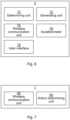
- Fig 6 is a schematic diagram illustrating units of the key device 2 of Fig 1 according to one embodiment.
- the units are implemented using circuits adapted for the functionality described herein.
- the units can be implemented using any one or more of an ASIC (Application Specific Integrated Circuit), an FPGA (Field Programmable Gate Array), a processor or discrete logical circuits.
- ASIC Application Specific Integrated Circuit
- FPGA Field Programmable Gate Array
- a determining unit 70 is configured to determine when a user is under duress.
- the determining unit 70 determines that a user is under duress by detecting a predetermined movement pattern using an accelerometer 78 in the key device. For instance, the user can in this way signal duress by moving the key device in a circle, or tapping the key device against a leg a predetermined number of times or using a predetermined pattern, or any other suitable predetermined movement.
- the determining unit 70 can determine that a user is under duress by detecting a user interface interaction. For instance, the user can in this way signal duress by performing a long press or hard press on a user interface element (such as a hard key or a button on a touch screen) of a user interface 70.
- This user interface element is optionally used for regular interaction to unlock the lock device, when the user interacts with this user interface element in a normal (i.e. not hard, long, etc.) way. In this way, it is difficult for the attacker to see that the user is signalling duress, which increases security for the user.
- a generating unit 72 is configured to generate a duress signal.
- the duress signal can be a separate signal or the duress signal can be a duress indicator (e.g. a flag or parameter value) in an access control message.
- the duress signal is a duress indicator in the access control message, signalling is reduced.
- the access control message can e.g. be a message to request access or a message used in the access control procedure as known in the art per se.
- a wireless communication unit 74 is configured to establish a communication channel with a lock device.
- the communication channel is intended to be used (also) for access control signalling.
- the wireless communication unit 74 can employ any suitable wireless communication standard in the communication with the lock device. For instance Bluetooth or Bluetooth Low Energy (BLE), ZigBee, any of the IEEE 802.11x standards (also known as WiFi), etc.
- the wireless communication unit 74 is further configured to transmit, over the communication channel, the duress signal to the lock device.
- the communication channel which is used for regular access control also, existing structures are used for the duress signalling. This improves reliability of the duress signalling, since the person threatening the user of course needs the user to unlock the lock device to enter the restricted physical space.
- the communication channel which is necessary for unlocking the lock device is also used for signalling duress.
- a user interface unit 78 comprises one or more components for providing a user interface.
- the user interface unit 78 can comprise a display, optionally a touch screen, physical buttons, microphone, speaker, etc.
- the user interface unit 68 received input from the user 7 and provides output to the user 7.
- the key device 2 is also configured to communicate with the lock device for access control signalling as known in the art per se.
- the access control can be based on delegations, where, when the key device is presented for a lock device, the lock device checks that there is a valid delegation path from the lock device to the key device.
- the delegation path contains a plurality of chain linked delegations which starts in the lock device and ends in the key device. Each delegation is a delegation of an access right for the lock device from a delegator to a receiver.
- the delegation path can contain delegation(s) being locally stored by the lock device and delegation(s) communicated from the key device.
- the delegation path can contain an arbitrary number of delegations. Some or all delegations can be authenticated using a digital signature.
- Fig 7 is a schematic diagram illustrating units of the unclaimed lock device 1 of Fig 1 according to one embodiment.
- the units are implemented using circuits adapted for the functionality described herein.
- the units can be implemented using any one or more of an ASIC (Application Specific Integrated Circuit), an FPGA (Field Programmable Gate Array), a processor or discrete logical circuits.
- ASIC Application Specific Integrated Circuit
- FPGA Field Programmable Gate Array
- a wireless communication unit 80 is configured to establish a communication channel with a key device, the communication channel being intended to be used (also) for access control signalling.
- the wireless communication unit 80 is further configured to receive, over the communication channel, a duress signal from the lock device.
- An action determining unit 82 is configured to performs a duress action when a duress signal has been received (by the wireless communication unit 80).
- the duress action can comprise transmitting a duress signal to an external server, without triggering an audible alarm.
- the external server can e.g. be a server of an alarm company, the employer of the user, etc.
- the duress action can be used to signal a threatening situation to the external server, which can trigger a response, e.g. to send someone to help the user.
- the communication channel which is used for regular access control also, existing structures are used for the duress signalling. This improves reliability of the duress signalling, since the person threatening the user of course needs the user to unlock the lock device to enter the restricted physical space.
- the communication channel which is necessary for unlocking the lock device is also used for signalling duress.
- the lock device 1 is also configured to communicate with the key device 2 for access control signalling as known in the art per se.
- the access control can be based on delegations, where, when the key device is presented for a lock device, the lock device checks that there is a valid delegation path from the lock device to the key device.
- the delegation path contains a plurality of chain linked delegations which starts in the lock device and ends in the key device. Each delegation is a delegation of an access right for the lock device from a delegator to a receiver.
- the delegation path can contain delegation(s) being locally stored by the lock device and delegation(s) communicated from the key device.
- the delegation path can contain an arbitrary number of delegations. Some or all delegations can be authenticated using a digital signature.
Landscapes
- Engineering & Computer Science (AREA)
- Physics & Mathematics (AREA)
- General Physics & Mathematics (AREA)
- Computer Networks & Wireless Communication (AREA)
- Business, Economics & Management (AREA)
- Emergency Management (AREA)
- Computer Security & Cryptography (AREA)
- Signal Processing (AREA)
- Health & Medical Sciences (AREA)
- Child & Adolescent Psychology (AREA)
- General Health & Medical Sciences (AREA)
- Mobile Radio Communication Systems (AREA)
- Lock And Its Accessories (AREA)
Description
- The invention relates to a key device, methods, computer programs and computer program products for signalling duress.
- Lock devices and key devices are evolving from the traditional pure mechanical locks. These days, there are wireless interfaces for electronic lock devices, e.g. by interacting with a key device. For instance, Radio Frequency Identification (RFID), Bluetooth Low Energy (BLE) etc. can be used for the communication between lock device and key device.
- However, situations of duress, i.e. threatening situations, can occur. A user can be attacked and forced to open a lock device using a key device in possession.
-
US 2013/091561 A1 discloses executing commands provided during user authentication.EP 2 262 292 A2EP 1 971 172 A1CN 104 100 169 A discloses coercion-against alarm method, coercion-against alarm device and system using coercion-against alarm device.US 2018/122219 A1 discloses invisible indication of duress via a wearable. - It is an object to provide an efficient way to signal duress from a user being at risk.
- According to a first aspect, it is provided a method performed by a key device for supporting duress signalling according to
claim 1. - The step of determining that a user is under distress may comprise determining that the user is under distress unless a user input indicating non-distress is detected.
- The step of exiting the wait state and establishing a wireless communication channel may be triggered when the key device comes into wireless communication range with the lock device.
- The step of determining that a user is under duress may comprise detecting a predetermined movement pattern using an accelerometer in the key device.
- The step of determining that a user is under duress may comprise detecting a user interface interaction by the key device.
- The step of generating the duress signal may comprise setting a duress indicator in an access control message.
- According to a second aspect, it is provided a key device for supporting duress signalling according to claim 7.
- The instructions to determine that a user is under distress may comprise instructions that, when executed by the processor, cause the key device to determine that the user is under distress unless a user input indicating non-distress is detected.
- The key device may further comprise instructions that, when executed by the processor, cause the key device to trigger the instructions to exit the wait state and establish a wireless communication channel when the key device comes into wireless communication range with the lock device.
- The instructions to determine that a user is under duress may comprise instructions that, when executed by the processor, cause the key device to detect a predetermined movement pattern using an accelerometer in the key device.
- The instructions to determine that a user is under duress may comprise instructions that, when executed by the processor, cause the key device to detect a user interface interaction by the key device.
- The instructions to generate the duress signal may comprise instructions that, when executed by the processor, cause the key device to set a duress indicator in an access control message.
- According to a third aspect, it is provided a computer program for supporting duress signalling according to claim 13.
- According to a fourth aspect, it is provided a computer program product comprising a computer program according to the third aspect and a computer readable means on which the computer program is stored. Generally, all terms used in the claims are to be interpreted according to their ordinary meaning in the technical field, unless explicitly defined otherwise herein. All references to "a/an/the element, apparatus, component, means, step, etc." are to be interpreted openly as referring to at least one instance of the element, apparatus, component, means, step, etc., unless explicitly stated otherwise.
- The invention is now described, by way of example, with reference to the accompanying drawings, in which:
-
Fig 1 is a schematic diagram showing an environment in which embodiments presented herein can be applied; -
Fig 2 is a flow chart illustrating embodiments of methods for supporting duress signalling, performed in the key device ofFig 1 ; -
Fig 3 is a flow chart illustrating embodiments of unclaimed methods for supporting duress signalling, performed in the lock device ofFig 1 ; -
Fig 4 is a schematic diagram illustrating components of the unclaimed lock device and the key device ofFig 1 ; -
Fig 5 shows one example of acomputer program product 90 comprising computer readable means; -
Fig 6 is a schematic diagram illustrating units of the key device ofFig 1 according to one embodiment; and -
Fig 7 is a schematic diagram illustrating units of the unclaimed lock device ofFig 1 according to one embodiment. - The invention will now be described more fully hereinafter with reference to the accompanying drawings, in which certain embodiments of the invention are shown. This invention may, however, be embodied in many different forms and should not be construed as limited to the embodiments set forth herein; rather, these embodiments are provided by way of example so that this disclosure will be thorough and complete, and will fully convey the scope of the invention to those skilled in the art. Like numbers refer to like elements throughout the description.
- Embodiments presented herein are based on using a communication channel intended for access control communication also for signalling a duress situation.
-
Fig 1 is a schematic diagram showing an environment in which embodiments presented herein can be applied. Access to aphysical space 16 is restricted by an openable physical barrier 15, which is selectively unlockable. The barrier 15 stands between the restrictedphysical space 16 on the inside of the barrier 15 and an accessiblephysical space 14 on the outside of the barrier 15. Note that the accessiblephysical space 14 can be a restricted physical space in itself, but in relation to this particular barrier 15, the accessiblephysical space 14 is accessible. In other words, the restrictedphysical space 16 is inside the barrier 15 and the accessiblephysical space 14 is outside the physical barrier 15. In order to unlock the barrier 15, alock device 1 is provided. Thelock device 1 is controllable to be set in an unlocked state or locked state. - The
lock device 1 communicates with akey device 2 over awireless communication channel 4. Thekey device 2 is any suitable device portable by a user and which can be used for authentication over thewireless communication channel 4. Thekey device 2 is typically carried or worn by the user 7 and may be implemented as a mobile phone, a smartphone, a key fob, wearable device, smart phone case, etc. Using wireless communication over thecommunication channel 4, using any suitable wireless interface, e.g. using Bluetooth or Bluetooth Low Energy (BLE), ZigBee, any of the IEEE 802.11x standards (also known as WiFi), etc., the authenticity and authority of thekey device 2 can be checked in an unlock procedure. Based on the result, thelock device 1 grants or denies access. As described in more detail below, the communication between thekey device 2 and thelock device 1 can be exploited for also communicating a duress signal. - The
lock device 1 can also communicate with anexternal server 8 using a communication network 6. The communication network can e.g. form part of the Internet and/or a cellular communication network. - When access is granted, the
lock device 1 is set in an unlocked state. When thelock device 1 is in an unlocked state, the barrier 15 can be opened and when thelock device 1 is in a locked state, the barrier 15 cannot be opened. In this way, access to theinside 16 of the barrier 15 is controlled by thelock device 1. It is to be noted that thelock device 1 can be mounted in a surrounding structure 17 (e.g. wall) by the physical barrier 15 (as shown) or in the physical barrier 15 (not shown). - If the user 7 is in a threatening situation, the user 7 is said to be under duress. For instance, the user 7 could be threatened by an attacker 3 to gain access to the restricted
physical space 16. A problem is then how the user 7 could signal this duress while keeping safe. This is solved according to the embodiments of the method described below. -
Fig 2 is a flow chart illustrating embodiments of methods for supporting duress signalling, performed in the key device ofFig 1 . - In a determine that a user is under
duress step 40, the key device determines that a user is under duress. - In one embodiment, the user is under determined to be under distress unless a user input indicating non-distress is detected. In other words, duress is then the default situation and the user needs to perform a certain action to deactivate the duress state. In this way, if the user does not deactivate the duress, duress is assumed and appropriate further measures are taken (e.g. alarming security personnel). With this embodiment, no special signalling is needed for duress (other than the absence of duress deactivation) whereby security for the user under duress is increased, since the attacker does not know that distress is signalled.
- In one embodiment, the key device determines that a user is under duress by detecting a predetermined movement pattern using an accelerometer in the key device. For instance, the user can in this way signal duress by moving the key device in a circle, or tapping the key device against a leg a predetermined number of times or using a predetermined pattern, or any other suitable predetermined movement.
- Alternatively or additionally, the key device can determine that a user is under duress by detecting a user interface interaction. For instance, the user can in this way signal duress by performing a long press or hard press on a user interface element (such as a button on a touch screen or a hard key). This user interface element is optionally used for regular interaction to unlock the lock device, when the user interacts with this user interface element in a normal (i.e. not hard, long, etc.) way. In this way, it is difficult for the attacker to see that the user is signalling duress, which increases security for the user.
- In an enter
wait state step 42, the key device enters a wait state after it has been determined that the user is under duress. In this way, the detection of duress can occur in advance to any access control signalling with the lock device. The wait state is a state where the method waits until a trigger causes the key device to exit the wait state. - In an exit wait state and establish
communication channel step 44, the key device exits the wait state and establishes a communication channel with a lock device. This step can be triggered when the key device comes into communication range with the lock device. Alternatively or additionally, this step can be triggered by receiving a user input indicating that the user requests the lock device to be unlocked. By using the wait state and only exiting the wait state when access control is triggered, the duress determination can occur in advance to requesting access, i.e. seconds or minutes prior to requesting access. In this way, when access is requested, if the user is under duress, the user does not need to do anything out of the ordinary to signal duress, which might otherwise raise suspicion with the attacker and compromise personal security for the user under duress. The communication channel is intended to be used (also) for access control signalling. - In a generate
duress signal step 45, the key device generates a duress signal. The duress signal can be a separate signal or the duress signal can be a duress indicator (e.g. a flag or parameter value) in an access control message. When the duress signal is a duress indicator in the access control message, signalling is reduced. The access control message can e.g. be a message to request access or a message used in the access control procedure as known in the art per se. It is to be noted that this step can equally well be performed beforestep 44 or even beforestep 42. - In a transmit
duress signal step 46, the key device transmits, over the communication channel, the duress signal to the lock device. By using the communication channel, which is used for regular access control also, existing structures are used for the duress signalling. This improves reliability of the duress signalling, since the person threatening the user of course needs the user to unlock the lock device to enter the restricted physical space. In other words, the communication channel which is necessary for unlocking the lock device is also used for signalling duress. - After, or combined with,
step 46, the key device communicates with the lock device for access control signalling as known in the art per se. - For instance, the access control can be based on delegations, where, when the key device is presented for a lock device, the lock device checks that there is a valid delegation path from the lock device to the key device. The delegation path contains a plurality of chain linked delegations which starts in the lock device and ends in the key device. Each delegation is a delegation of an access right for the lock device from a delegator to a receiver. The delegation path can contain delegation(s) being locally stored by the lock device and delegation(s) communicated from the key device. The delegation path can contain an arbitrary number of delegations. Some or all delegations can be authenticated using a digital signature.
- Using the delegation path, great flexibility is achieved in how access rights are provided. Since no central point of control is needed, massive scalability is achieved. Moreover, there is no single point of failure, which improves reliability.
-
Fig 3 is a flow chart illustrating embodiments of unclaimed methods for supporting duress signalling, performed in the lock device ofFig 1 . - In an establish
communication channel step 50, the lock device establishes a communication channel with a key device, the communication channel being intended to be used (also) for access control signalling. This step corresponds to step 44 described above. - In a receive
duress signal step 52, the lock device receives, over the communication channel, a duress signal from the lock device. This step corresponds to step 46 described above. - In a perform
duress action step 54, the lock device performs a duress action. The duress action can comprise transmitting a duress signal to an external server, without triggering an audible alarm. The external server can e.g. be a server of an alarm company, the employer of the user, etc. In other words, the duress action can be used to signal a threatening situation to the external server, which can trigger a response, e.g. to send someone to help the user. -
Fig 4 is a schematic diagram illustrating components of theunclaimed lock device 1 and thekey device 2 ofFig 1 . Aprocessor 60 is provided using any combination of one or more of a suitable central processing unit (CPU), multiprocessor, microcontroller, digital signal processor (DSP), etc., capable of executingsoftware instructions 67 stored in amemory 64, which can thus be a computer program product. Theprocessor 60 could alternatively be implemented using an ASIC, FPGA, etc. Theprocessor 60 can be configured to execute the method described with reference toFig 2 (for the key device 2) andFig 3 (for the lock device 1) above. - The
memory 64 can be any combination of random access memory (RAM) and/or read only memory (ROM). Thememory 64 also comprises persistent storage, which, for example, can be any single one or combination of magnetic memory, optical memory, solid-state memory or even remotely mounted memory. - A
data memory 66 is also provided for reading and/or storing data during execution of software instructions in theprocessor 60. Thedata memory 66 can be any combination of RAM and/or ROM. - An I/O interface 62 is provided for communicating with external and/or internal entities. Optionally, the I/O interface 62 also includes a user interface.
- Other components are omitted in order not to obscure the concepts presented herein.
-
Fig 5 shows one example of acomputer program product 90 comprising computer readable means. On this computer readable means, acomputer program 91 can be stored, which computer program can cause a processor to execute a method according to embodiments described herein. In this example, the computer program product is an optical disc, such as a CD (compact disc) or a DVD (digital versatile disc) or a Blu-Ray disc. As explained above, the computer program product could also be embodied in a memory of a device, such as thecomputer program product 64 ofFig 4 . While thecomputer program 91 is here schematically shown as a track on the depicted optical disk, the computer program can be stored in any way which is suitable for the computer program product, such as a removable solid state memory, e.g. a Universal Serial Bus (USB) drive. -
Fig 6 is a schematic diagram illustrating units of thekey device 2 ofFig 1 according to one embodiment. The units are implemented using circuits adapted for the functionality described herein. For instance, the units can be implemented using any one or more of an ASIC (Application Specific Integrated Circuit), an FPGA (Field Programmable Gate Array), a processor or discrete logical circuits. - A determining
unit 70 is configured to determine when a user is under duress. In one embodiment, the determiningunit 70 determines that a user is under duress by detecting a predetermined movement pattern using anaccelerometer 78 in the key device. For instance, the user can in this way signal duress by moving the key device in a circle, or tapping the key device against a leg a predetermined number of times or using a predetermined pattern, or any other suitable predetermined movement. - Alternatively or additionally, the determining
unit 70 can determine that a user is under duress by detecting a user interface interaction. For instance, the user can in this way signal duress by performing a long press or hard press on a user interface element (such as a hard key or a button on a touch screen) of auser interface 70. This user interface element is optionally used for regular interaction to unlock the lock device, when the user interacts with this user interface element in a normal (i.e. not hard, long, etc.) way. In this way, it is difficult for the attacker to see that the user is signalling duress, which increases security for the user. - A generating
unit 72 is configured to generate a duress signal. The duress signal can be a separate signal or the duress signal can be a duress indicator (e.g. a flag or parameter value) in an access control message. When the duress signal is a duress indicator in the access control message, signalling is reduced. The access control message can e.g. be a message to request access or a message used in the access control procedure as known in the art per se. - A
wireless communication unit 74 is configured to establish a communication channel with a lock device. The communication channel is intended to be used (also) for access control signalling. Thewireless communication unit 74 can employ any suitable wireless communication standard in the communication with the lock device. For instance Bluetooth or Bluetooth Low Energy (BLE), ZigBee, any of the IEEE 802.11x standards (also known as WiFi), etc. - The
wireless communication unit 74 is further configured to transmit, over the communication channel, the duress signal to the lock device. By using the communication channel, which is used for regular access control also, existing structures are used for the duress signalling. This improves reliability of the duress signalling, since the person threatening the user of course needs the user to unlock the lock device to enter the restricted physical space. In other words, the communication channel which is necessary for unlocking the lock device is also used for signalling duress. - A
user interface unit 78 comprises one or more components for providing a user interface. For instance, theuser interface unit 78 can comprise a display, optionally a touch screen, physical buttons, microphone, speaker, etc. The user interface unit 68 received input from the user 7 and provides output to the user 7. - The
key device 2 is also configured to communicate with the lock device for access control signalling as known in the art per se. For instance, the access control can be based on delegations, where, when the key device is presented for a lock device, the lock device checks that there is a valid delegation path from the lock device to the key device. The delegation path contains a plurality of chain linked delegations which starts in the lock device and ends in the key device. Each delegation is a delegation of an access right for the lock device from a delegator to a receiver. The delegation path can contain delegation(s) being locally stored by the lock device and delegation(s) communicated from the key device. The delegation path can contain an arbitrary number of delegations. Some or all delegations can be authenticated using a digital signature. - Using the delegation path, great flexibility is achieved in how access rights are provided. Since no central point of control is needed, massive scalability is achieved. Moreover, there is no single point of failure, which improves reliability.
- Other components of the
key device 2 are omitted in order not to obscure the concepts presented herein. -
Fig 7 is a schematic diagram illustrating units of theunclaimed lock device 1 ofFig 1 according to one embodiment. The units are implemented using circuits adapted for the functionality described herein. For instance, the units can be implemented using any one or more of an ASIC (Application Specific Integrated Circuit), an FPGA (Field Programmable Gate Array), a processor or discrete logical circuits. - A
wireless communication unit 80 is configured to establish a communication channel with a key device, the communication channel being intended to be used (also) for access control signalling. - The
wireless communication unit 80 is further configured to receive, over the communication channel, a duress signal from the lock device. - An
action determining unit 82 is configured to performs a duress action when a duress signal has been received (by the wireless communication unit 80). The duress action can comprise transmitting a duress signal to an external server, without triggering an audible alarm. The external server can e.g. be a server of an alarm company, the employer of the user, etc. In other words, the duress action can be used to signal a threatening situation to the external server, which can trigger a response, e.g. to send someone to help the user. - By using the communication channel, which is used for regular access control also, existing structures are used for the duress signalling. This improves reliability of the duress signalling, since the person threatening the user of course needs the user to unlock the lock device to enter the restricted physical space. In other words, the communication channel which is necessary for unlocking the lock device is also used for signalling duress.
- The
lock device 1 is also configured to communicate with thekey device 2 for access control signalling as known in the art per se. For instance, the access control can be based on delegations, where, when the key device is presented for a lock device, the lock device checks that there is a valid delegation path from the lock device to the key device. The delegation path contains a plurality of chain linked delegations which starts in the lock device and ends in the key device. Each delegation is a delegation of an access right for the lock device from a delegator to a receiver. The delegation path can contain delegation(s) being locally stored by the lock device and delegation(s) communicated from the key device. The delegation path can contain an arbitrary number of delegations. Some or all delegations can be authenticated using a digital signature. - Using the delegation path, great flexibility is achieved in how access rights are provided. Since no central point of control is needed, massive scalability is achieved. Moreover, there is no single point of failure, which improves reliability.
- The invention has mainly been described above with reference to a few embodiments. However, as is readily appreciated by a person skilled in the art, other embodiments than the ones disclosed above are equally possible within the scope of the invention, as defined by the appended patent claims.
Claims (14)
- A method performed by a key device (2) for supporting duress signalling, the key device being portable and usable for authentication over a wireless communication channel with a lock device, the method comprising the steps of:determining (40) that a user (7) is under duress;entering (42) a wait state after the step of determining (40) that a user (7) is under duress;exiting (44) the wait state and establishing a wireless communication channel (4) with a lock device (1), the wireless communication channel being intended to be used for access control signalling;generating (45) a duress signal;transmitting (46), over the wireless communication channel (4), the duress signal to the lock device (1); andwherein the step of exiting (44) the wait state and establishing a wireless communication channel is triggered by receiving a user input indicating that the user requests the lock device to be unlocked to gain access to a restricted physical space.
- The method according to claim 1, wherein the step of determining (40) that a user (7) is under duress comprises determining that the user is under duress unless a user input indicating non-duress is detected.
- The method according to claim 1 or 2, wherein the step of exiting (44) the wait state and establishing a wireless communication channel is triggered when the key device comes into wireless communication range with the lock device.
- The method according to any one of the preceding claims, wherein the step of determining (40) that a user (7) is under duress comprises detecting a predetermined movement pattern using an accelerometer in the key device (2).
- The method according to any one of claims 1 to 4, wherein the step of determining (40) that a user (7) is under duress comprises detecting a user interface interaction by the key device (2).
- The method according to any one of the preceding claims, wherein the step of generating (45) the duress signal comprises setting a duress indicator in an access control message.
- A key device (2) for supporting duress signalling, the key device being portable and usable for authentication over a wireless communication channel with a lock device, the key device (2) comprising:a processor (60); anda memory (64) storing instructions (67) that, when executed by the processor, cause the key device (2) to:determine that a user (7) is under duress;enter a wait state after the instructions to determine that a user (7) is under duress;exit the wait state and establish a wireless communication channel (4) with a lock device (1), the wireless communication channel being intended to be used for access control signalling;generate a duress signal;transmit, over the wireless communication channel (4), the duress signal to the lock device (1); andtrigger the instructions to exit the wait state and establishing a wireless communication channel when receiving a user input indicating that the user requests the lock device to be unlocked.
- The key device (2) according to claim 7, wherein the instructions to determine that a user (7) is under duress comprise instructions (67) that, when executed by the processor, cause the key device (2) to determine that the user is under duress unless a user input indicating non-duress is detected.
- The key device (2) according to claim 7 or 8, further comprising instructions (67) that, when executed by the processor, cause the key device (2) to trigger the instructions to exit the wait state and establish a wireless communication channel when the key device comes into wireless communication range with the lock device.
- The key device (2) according to any one of claims 7 to 9, wherein the instructions to determine that a user (7) is under duress comprise instructions (67) that, when executed by the processor, cause the key device (2) to detect a predetermined movement pattern using an accelerometer in the key device (2).
- The key device (2) according to any one of claims 7 to 10, wherein the instructions to determine that a user (7) is under duress comprise instructions (67) that, when executed by the processor, cause the key device (2) to detect a user interface interaction by the key device (2).
- The key device (2) according to any one of claims 7 to 11, wherein the instructions to generate the duress signal comprise instructions (67) that, when executed by the processor, cause the key device (2) to set a duress indicator in an access control message.
- A computer program (67, 91) for supporting duress signalling using a key device being portable and usable for authentication over a wireless communication channel with a lock device, the computer program comprising computer program code which, when run on the key device (2) causes the key device (2) to:determine that a user (7) is under duress;enter a wait state after the computer program code is run to determine that a user (7) is under duress;exit the wait state and establish a wireless communication channel (4) with a lock device (1), the wireless communication channel being intended to be used for access control signalling;generate a duress signal;transmit, over the wireless communication channel (4), the duress signal to the lock device (1); andtrigger the computer program code to exit the wait state and establishing a wireless communication channel when receiving a user input indicating that the user requests the lock device to be unlocked.
- A computer program product (64, 90) comprising a computer program according to claim 13 and a computer readable means on which the computer program is stored.
Applications Claiming Priority (2)
| Application Number | Priority Date | Filing Date | Title |
|---|---|---|---|
| SE1851439 | 2018-11-20 | ||
| PCT/EP2019/081763 WO2020104439A1 (en) | 2018-11-20 | 2019-11-19 | Signalling duress |
Publications (2)
| Publication Number | Publication Date |
|---|---|
| EP3884473A1 EP3884473A1 (en) | 2021-09-29 |
| EP3884473B1 true EP3884473B1 (en) | 2024-10-23 |
Family
ID=68621290
Family Applications (1)
| Application Number | Title | Priority Date | Filing Date |
|---|---|---|---|
| EP19806196.2A Active EP3884473B1 (en) | 2018-11-20 | 2019-11-19 | Signalling duress |
Country Status (5)
| Country | Link |
|---|---|
| US (1) | US11436912B2 (en) |
| EP (1) | EP3884473B1 (en) |
| CN (2) | CN111212393A (en) |
| FI (1) | FI3884473T3 (en) |
| WO (1) | WO2020104439A1 (en) |
Citations (2)
| Publication number | Priority date | Publication date | Assignee | Title |
|---|---|---|---|---|
| CN104100169A (en) * | 2013-04-02 | 2014-10-15 | 新谊整合科技股份有限公司 | Anti-coercion alarm method, device and system using the anti-coercion alarm device |
| US20180122219A1 (en) * | 2015-05-01 | 2018-05-03 | Assa Abloy Ab | Invisible indication of duress via wearable |
Family Cites Families (21)
| Publication number | Priority date | Publication date | Assignee | Title |
|---|---|---|---|---|
| GB9017153D0 (en) | 1990-08-03 | 1990-09-19 | Intelligent Locking Sys Ltd | A security lock for a closure member |
| CN2106200U (en) * | 1991-12-06 | 1992-06-03 | 王族伟 | Self-theft-proof coerce-proof forced alarm for cipher lock |
| AU2001293248A1 (en) * | 2000-10-03 | 2002-04-15 | Abraham R. Zingher | Biometric system and method for detecting duress transactions |
| CN1207691C (en) * | 2001-02-08 | 2005-06-22 | 史秋华 | Antitheft and antirobbing security system for noble objects (paper money or confidential document) |
| US6833785B2 (en) | 2002-03-07 | 2004-12-21 | International Business Machines Corporation | Vehicle security system |
| CN1441380A (en) * | 2003-01-08 | 2003-09-10 | 章映东 | Vital fingerprint distinguishing technology for identity antifake and resisting forcing |
| AU2003904317A0 (en) | 2003-08-13 | 2003-08-28 | Securicom (Nsw) Pty Ltd | Remote entry system |
| EP2262292B1 (en) | 2004-02-26 | 2016-08-17 | BlackBerry Limited | Mobile communications device with security features |
| DE602007002270D1 (en) | 2007-03-13 | 2009-10-15 | Research In Motion Ltd | Improved coping with compulsory situations |
| CN202008725U (en) * | 2010-07-29 | 2011-10-12 | 刘秉忠 | Active defense security mechanism |
| CN102110320A (en) * | 2010-12-23 | 2011-06-29 | 汉王科技股份有限公司 | Coerce alarm method and entrance guard control equipment in entrance guard system |
| US20130091561A1 (en) * | 2011-10-11 | 2013-04-11 | Keisey L. Bruso | Executing commands provided during user authentication |
| CN102737427A (en) * | 2012-05-28 | 2012-10-17 | 河北莱恩科技有限责任公司 | ATM dynamic privilege management system |
| CN202689791U (en) * | 2012-06-13 | 2013-01-23 | 深圳市智明恒通科技有限公司 | Intelligent safety box antitheft system of safe case |
| CN103287322B (en) * | 2013-05-30 | 2015-09-09 | 浙江吉利汽车研究院有限公司杭州分公司 | Driving safety device |
| ES2448942A1 (en) | 2013-10-17 | 2014-03-17 | Arcas Olle, S.L. | Safety box and security system comprising said safe |
| US9672727B1 (en) * | 2013-11-05 | 2017-06-06 | Alarm.Com Incorporated | Handling duress input |
| WO2015191720A1 (en) * | 2014-06-10 | 2015-12-17 | Rapid Response System I/P, Llc | Response system and method |
| US9773364B2 (en) * | 2014-07-28 | 2017-09-26 | Dan Kerning | Security and public safety application for a mobile device with audio/video analytics and access control authentication |
| CN204946138U (en) * | 2015-09-15 | 2016-01-06 | 劳海鹏 | A kind of by coerce unblank judgement, report to the police and the system of information screen |
| WO2018075153A1 (en) | 2016-10-17 | 2018-04-26 | Abner Roy T | Network connectivity module for electro-mechanical locks |
-
2019
- 2019-01-09 CN CN201910019487.0A patent/CN111212393A/en active Pending
- 2019-11-19 EP EP19806196.2A patent/EP3884473B1/en active Active
- 2019-11-19 CN CN201980076271.6A patent/CN113168741B/en active Active
- 2019-11-19 FI FIEP19806196.2T patent/FI3884473T3/en active
- 2019-11-19 US US17/293,414 patent/US11436912B2/en active Active
- 2019-11-19 WO PCT/EP2019/081763 patent/WO2020104439A1/en not_active Ceased
Patent Citations (2)
| Publication number | Priority date | Publication date | Assignee | Title |
|---|---|---|---|---|
| CN104100169A (en) * | 2013-04-02 | 2014-10-15 | 新谊整合科技股份有限公司 | Anti-coercion alarm method, device and system using the anti-coercion alarm device |
| US20180122219A1 (en) * | 2015-05-01 | 2018-05-03 | Assa Abloy Ab | Invisible indication of duress via wearable |
Also Published As
| Publication number | Publication date |
|---|---|
| CN113168741B (en) | 2023-09-01 |
| EP3884473A1 (en) | 2021-09-29 |
| US11436912B2 (en) | 2022-09-06 |
| CN113168741A (en) | 2021-07-23 |
| US20220051551A1 (en) | 2022-02-17 |
| CN111212393A (en) | 2020-05-29 |
| FI3884473T3 (en) | 2024-11-25 |
| WO2020104439A1 (en) | 2020-05-28 |
Similar Documents
| Publication | Publication Date | Title |
|---|---|---|
| AU2014331198B2 (en) | Access control using portable electronic devices | |
| US20200329037A1 (en) | Security system with a wireless security device | |
| US20080238669A1 (en) | Door entry security device with electronic lock | |
| JP2013217142A (en) | State control system, and state control method | |
| EP3068109B1 (en) | Method of performing sensor operations based on their relative location with respect to a user | |
| EP3072754A1 (en) | Method, device, computer program and computer program product for determining whether a portable key device is located in an active area in relation to a barrier | |
| US9779225B2 (en) | Method and system to provide access to secure features of a device | |
| KR101617872B1 (en) | Alert method and system of fingerprint reader | |
| EP3899880B1 (en) | Emergency delegation | |
| KR20140093556A (en) | Security System Using Two factor Authentication And Security Method of Electronic Equipment Using Thereof | |
| US11436912B2 (en) | Signalling duress | |
| US11803626B2 (en) | Wireless kill switch | |
| EP4064740B1 (en) | Method of proximity detection between two devices | |
| EP3379497A1 (en) | Secure authentication for access control, home control, and alarm systems | |
| JP4748048B2 (en) | Authentication system | |
| JP6919763B2 (en) | Wireless communication device and entry / exit management system | |
| WO2022101245A1 (en) | Controlling access based on a machine-learning model | |
| KR20230161748A (en) | System for configuring smart blockchain city | |
| KR20120110590A (en) | Locking device, system and method using vibration and recording medium for the same | |
| HK1224789A1 (en) | Access control method and access control system |
Legal Events
| Date | Code | Title | Description |
|---|---|---|---|
| STAA | Information on the status of an ep patent application or granted ep patent |
Free format text: STATUS: UNKNOWN |
|
| STAA | Information on the status of an ep patent application or granted ep patent |
Free format text: STATUS: THE INTERNATIONAL PUBLICATION HAS BEEN MADE |
|
| PUAI | Public reference made under article 153(3) epc to a published international application that has entered the european phase |
Free format text: ORIGINAL CODE: 0009012 |
|
| STAA | Information on the status of an ep patent application or granted ep patent |
Free format text: STATUS: REQUEST FOR EXAMINATION WAS MADE |
|
| 17P | Request for examination filed |
Effective date: 20210520 |
|
| AK | Designated contracting states |
Kind code of ref document: A1 Designated state(s): AL AT BE BG CH CY CZ DE DK EE ES FI FR GB GR HR HU IE IS IT LI LT LU LV MC MK MT NL NO PL PT RO RS SE SI SK SM TR |
|
| DAV | Request for validation of the european patent (deleted) | ||
| DAX | Request for extension of the european patent (deleted) | ||
| P01 | Opt-out of the competence of the unified patent court (upc) registered |
Effective date: 20230530 |
|
| GRAP | Despatch of communication of intention to grant a patent |
Free format text: ORIGINAL CODE: EPIDOSNIGR1 |
|
| STAA | Information on the status of an ep patent application or granted ep patent |
Free format text: STATUS: GRANT OF PATENT IS INTENDED |
|
| RIC1 | Information provided on ipc code assigned before grant |
Ipc: G08B 25/08 20060101ALN20231212BHEP Ipc: G08B 25/01 20060101ALN20231212BHEP Ipc: G07C 9/00 20200101AFI20231212BHEP |
|
| INTG | Intention to grant announced |
Effective date: 20240103 |
|
| GRAJ | Information related to disapproval of communication of intention to grant by the applicant or resumption of examination proceedings by the epo deleted |
Free format text: ORIGINAL CODE: EPIDOSDIGR1 |
|
| STAA | Information on the status of an ep patent application or granted ep patent |
Free format text: STATUS: REQUEST FOR EXAMINATION WAS MADE |
|
| INTC | Intention to grant announced (deleted) | ||
| GRAP | Despatch of communication of intention to grant a patent |
Free format text: ORIGINAL CODE: EPIDOSNIGR1 |
|
| STAA | Information on the status of an ep patent application or granted ep patent |
Free format text: STATUS: GRANT OF PATENT IS INTENDED |
|
| RIC1 | Information provided on ipc code assigned before grant |
Ipc: G08B 25/08 20060101ALN20240521BHEP Ipc: G08B 25/01 20060101ALN20240521BHEP Ipc: G07C 9/00 20200101AFI20240521BHEP |
|
| RIC1 | Information provided on ipc code assigned before grant |
Ipc: G08B 25/08 20060101ALN20240603BHEP Ipc: G08B 25/01 20060101ALN20240603BHEP Ipc: G07C 9/00 20200101AFI20240603BHEP |
|
| INTG | Intention to grant announced |
Effective date: 20240617 |
|
| GRAS | Grant fee paid |
Free format text: ORIGINAL CODE: EPIDOSNIGR3 |
|
| GRAA | (expected) grant |
Free format text: ORIGINAL CODE: 0009210 |
|
| STAA | Information on the status of an ep patent application or granted ep patent |
Free format text: STATUS: THE PATENT HAS BEEN GRANTED |
|
| AK | Designated contracting states |
Kind code of ref document: B1 Designated state(s): AL AT BE BG CH CY CZ DE DK EE ES FI FR GB GR HR HU IE IS IT LI LT LU LV MC MK MT NL NO PL PT RO RS SE SI SK SM TR |
|
| REG | Reference to a national code |
Ref country code: GB Ref legal event code: FG4D |
|
| RIN1 | Information on inventor provided before grant (corrected) |
Inventor name: GRAPE, FELIX Inventor name: SINGH, SONA |
|
| REG | Reference to a national code |
Ref country code: CH Ref legal event code: EP |
|
| REG | Reference to a national code |
Ref country code: DE Ref legal event code: R096 Ref document number: 602019060857 Country of ref document: DE |
|
| REG | Reference to a national code |
Ref country code: IE Ref legal event code: FG4D |
|
| REG | Reference to a national code |
Ref country code: FI Ref legal event code: FGE |
|
| REG | Reference to a national code |
Ref country code: LT Ref legal event code: MG9D |
|
| REG | Reference to a national code |
Ref country code: NL Ref legal event code: MP Effective date: 20241023 |
|
| REG | Reference to a national code |
Ref country code: AT Ref legal event code: MK05 Ref document number: 1735489 Country of ref document: AT Kind code of ref document: T Effective date: 20241023 |
|
| PG25 | Lapsed in a contracting state [announced via postgrant information from national office to epo] |
Ref country code: NL Free format text: LAPSE BECAUSE OF FAILURE TO SUBMIT A TRANSLATION OF THE DESCRIPTION OR TO PAY THE FEE WITHIN THE PRESCRIBED TIME-LIMIT Effective date: 20241023 |
|
| PG25 | Lapsed in a contracting state [announced via postgrant information from national office to epo] |
Ref country code: NL Free format text: LAPSE BECAUSE OF FAILURE TO SUBMIT A TRANSLATION OF THE DESCRIPTION OR TO PAY THE FEE WITHIN THE PRESCRIBED TIME-LIMIT Effective date: 20241023 |
|
| PG25 | Lapsed in a contracting state [announced via postgrant information from national office to epo] |
Ref country code: PT Free format text: LAPSE BECAUSE OF FAILURE TO SUBMIT A TRANSLATION OF THE DESCRIPTION OR TO PAY THE FEE WITHIN THE PRESCRIBED TIME-LIMIT Effective date: 20250224 Ref country code: HR Free format text: LAPSE BECAUSE OF FAILURE TO SUBMIT A TRANSLATION OF THE DESCRIPTION OR TO PAY THE FEE WITHIN THE PRESCRIBED TIME-LIMIT Effective date: 20241023 Ref country code: IS Free format text: LAPSE BECAUSE OF FAILURE TO SUBMIT A TRANSLATION OF THE DESCRIPTION OR TO PAY THE FEE WITHIN THE PRESCRIBED TIME-LIMIT Effective date: 20250223 |
|
| PG25 | Lapsed in a contracting state [announced via postgrant information from national office to epo] |
Ref country code: BG Free format text: LAPSE BECAUSE OF FAILURE TO SUBMIT A TRANSLATION OF THE DESCRIPTION OR TO PAY THE FEE WITHIN THE PRESCRIBED TIME-LIMIT Effective date: 20241023 |
|
| PG25 | Lapsed in a contracting state [announced via postgrant information from national office to epo] |
Ref country code: ES Free format text: LAPSE BECAUSE OF FAILURE TO SUBMIT A TRANSLATION OF THE DESCRIPTION OR TO PAY THE FEE WITHIN THE PRESCRIBED TIME-LIMIT Effective date: 20241023 |
|
| PG25 | Lapsed in a contracting state [announced via postgrant information from national office to epo] |
Ref country code: NO Free format text: LAPSE BECAUSE OF FAILURE TO SUBMIT A TRANSLATION OF THE DESCRIPTION OR TO PAY THE FEE WITHIN THE PRESCRIBED TIME-LIMIT Effective date: 20250123 |
|
| PG25 | Lapsed in a contracting state [announced via postgrant information from national office to epo] |
Ref country code: AT Free format text: LAPSE BECAUSE OF FAILURE TO SUBMIT A TRANSLATION OF THE DESCRIPTION OR TO PAY THE FEE WITHIN THE PRESCRIBED TIME-LIMIT Effective date: 20241023 Ref country code: GR Free format text: LAPSE BECAUSE OF FAILURE TO SUBMIT A TRANSLATION OF THE DESCRIPTION OR TO PAY THE FEE WITHIN THE PRESCRIBED TIME-LIMIT Effective date: 20250124 Ref country code: LV Free format text: LAPSE BECAUSE OF FAILURE TO SUBMIT A TRANSLATION OF THE DESCRIPTION OR TO PAY THE FEE WITHIN THE PRESCRIBED TIME-LIMIT Effective date: 20241023 |
|
| PG25 | Lapsed in a contracting state [announced via postgrant information from national office to epo] |
Ref country code: PL Free format text: LAPSE BECAUSE OF FAILURE TO SUBMIT A TRANSLATION OF THE DESCRIPTION OR TO PAY THE FEE WITHIN THE PRESCRIBED TIME-LIMIT Effective date: 20241023 |
|
| PG25 | Lapsed in a contracting state [announced via postgrant information from national office to epo] |
Ref country code: RS Free format text: LAPSE BECAUSE OF FAILURE TO SUBMIT A TRANSLATION OF THE DESCRIPTION OR TO PAY THE FEE WITHIN THE PRESCRIBED TIME-LIMIT Effective date: 20250123 |
|
| REG | Reference to a national code |
Ref country code: CH Ref legal event code: PL |
|
| PG25 | Lapsed in a contracting state [announced via postgrant information from national office to epo] |
Ref country code: SM Free format text: LAPSE BECAUSE OF FAILURE TO SUBMIT A TRANSLATION OF THE DESCRIPTION OR TO PAY THE FEE WITHIN THE PRESCRIBED TIME-LIMIT Effective date: 20241023 |
|
| PG25 | Lapsed in a contracting state [announced via postgrant information from national office to epo] |
Ref country code: MC Free format text: LAPSE BECAUSE OF FAILURE TO SUBMIT A TRANSLATION OF THE DESCRIPTION OR TO PAY THE FEE WITHIN THE PRESCRIBED TIME-LIMIT Effective date: 20241023 |
|
| PG25 | Lapsed in a contracting state [announced via postgrant information from national office to epo] |
Ref country code: DK Free format text: LAPSE BECAUSE OF FAILURE TO SUBMIT A TRANSLATION OF THE DESCRIPTION OR TO PAY THE FEE WITHIN THE PRESCRIBED TIME-LIMIT Effective date: 20241023 |
|
| PG25 | Lapsed in a contracting state [announced via postgrant information from national office to epo] |
Ref country code: LU Free format text: LAPSE BECAUSE OF NON-PAYMENT OF DUE FEES Effective date: 20241119 |
|
| REG | Reference to a national code |
Ref country code: CH Ref legal event code: PL |
|
| PG25 | Lapsed in a contracting state [announced via postgrant information from national office to epo] |
Ref country code: EE Free format text: LAPSE BECAUSE OF FAILURE TO SUBMIT A TRANSLATION OF THE DESCRIPTION OR TO PAY THE FEE WITHIN THE PRESCRIBED TIME-LIMIT Effective date: 20241023 |
|
| PG25 | Lapsed in a contracting state [announced via postgrant information from national office to epo] |
Ref country code: CH Free format text: LAPSE BECAUSE OF NON-PAYMENT OF DUE FEES Effective date: 20241130 |
|
| PG25 | Lapsed in a contracting state [announced via postgrant information from national office to epo] |
Ref country code: RO Free format text: LAPSE BECAUSE OF FAILURE TO SUBMIT A TRANSLATION OF THE DESCRIPTION OR TO PAY THE FEE WITHIN THE PRESCRIBED TIME-LIMIT Effective date: 20241023 |
|
| REG | Reference to a national code |
Ref country code: DE Ref legal event code: R097 Ref document number: 602019060857 Country of ref document: DE |
|
| PG25 | Lapsed in a contracting state [announced via postgrant information from national office to epo] |
Ref country code: SK Free format text: LAPSE BECAUSE OF FAILURE TO SUBMIT A TRANSLATION OF THE DESCRIPTION OR TO PAY THE FEE WITHIN THE PRESCRIBED TIME-LIMIT Effective date: 20241023 |
|
| PG25 | Lapsed in a contracting state [announced via postgrant information from national office to epo] |
Ref country code: CZ Free format text: LAPSE BECAUSE OF FAILURE TO SUBMIT A TRANSLATION OF THE DESCRIPTION OR TO PAY THE FEE WITHIN THE PRESCRIBED TIME-LIMIT Effective date: 20241023 |
|
| PG25 | Lapsed in a contracting state [announced via postgrant information from national office to epo] |
Ref country code: IT Free format text: LAPSE BECAUSE OF FAILURE TO SUBMIT A TRANSLATION OF THE DESCRIPTION OR TO PAY THE FEE WITHIN THE PRESCRIBED TIME-LIMIT Effective date: 20241023 |
|
| REG | Reference to a national code |
Ref country code: BE Ref legal event code: MM Effective date: 20241130 |
|
| PLBE | No opposition filed within time limit |
Free format text: ORIGINAL CODE: 0009261 |
|
| STAA | Information on the status of an ep patent application or granted ep patent |
Free format text: STATUS: NO OPPOSITION FILED WITHIN TIME LIMIT |
|
| PG25 | Lapsed in a contracting state [announced via postgrant information from national office to epo] |
Ref country code: SE Free format text: LAPSE BECAUSE OF FAILURE TO SUBMIT A TRANSLATION OF THE DESCRIPTION OR TO PAY THE FEE WITHIN THE PRESCRIBED TIME-LIMIT Effective date: 20241023 |
|
| 26N | No opposition filed |
Effective date: 20250724 |
|
| PG25 | Lapsed in a contracting state [announced via postgrant information from national office to epo] |
Ref country code: BE Free format text: LAPSE BECAUSE OF NON-PAYMENT OF DUE FEES Effective date: 20241130 |
|
| PG25 | Lapsed in a contracting state [announced via postgrant information from national office to epo] |
Ref country code: FR Free format text: LAPSE BECAUSE OF NON-PAYMENT OF DUE FEES Effective date: 20241223 |
|
| PG25 | Lapsed in a contracting state [announced via postgrant information from national office to epo] |
Ref country code: IE Free format text: LAPSE BECAUSE OF NON-PAYMENT OF DUE FEES Effective date: 20241119 |
|
| PGFP | Annual fee paid to national office [announced via postgrant information from national office to epo] |
Ref country code: DE Payment date: 20251007 Year of fee payment: 7 |
|
| PGFP | Annual fee paid to national office [announced via postgrant information from national office to epo] |
Ref country code: GB Payment date: 20251016 Year of fee payment: 7 |
|
| PGFP | Annual fee paid to national office [announced via postgrant information from national office to epo] |
Ref country code: FI Payment date: 20251113 Year of fee payment: 7 |
|
| PG25 | Lapsed in a contracting state [announced via postgrant information from national office to epo] |
Ref country code: HU Free format text: LAPSE BECAUSE OF FAILURE TO SUBMIT A TRANSLATION OF THE DESCRIPTION OR TO PAY THE FEE WITHIN THE PRESCRIBED TIME-LIMIT; INVALID AB INITIO Effective date: 20191119 |
|
| PG25 | Lapsed in a contracting state [announced via postgrant information from national office to epo] |
Ref country code: CY Free format text: LAPSE BECAUSE OF FAILURE TO SUBMIT A TRANSLATION OF THE DESCRIPTION OR TO PAY THE FEE WITHIN THE PRESCRIBED TIME-LIMIT; INVALID AB INITIO Effective date: 20191119 |