EP3884232B1 - Distributor, heat exchanger unit and air conditioner - Google Patents
Distributor, heat exchanger unit and air conditioner Download PDFInfo
- Publication number
- EP3884232B1 EP3884232B1 EP20765637.2A EP20765637A EP3884232B1 EP 3884232 B1 EP3884232 B1 EP 3884232B1 EP 20765637 A EP20765637 A EP 20765637A EP 3884232 B1 EP3884232 B1 EP 3884232B1
- Authority
- EP
- European Patent Office
- Prior art keywords
- pipe
- distributor
- refrigerant
- branched
- distribution paths
- Prior art date
- Legal status (The legal status is an assumption and is not a legal conclusion. Google has not performed a legal analysis and makes no representation as to the accuracy of the status listed.)
- Active
Links
Images













Classifications
-
- F—MECHANICAL ENGINEERING; LIGHTING; HEATING; WEAPONS; BLASTING
- F28—HEAT EXCHANGE IN GENERAL
- F28F—DETAILS OF HEAT-EXCHANGE AND HEAT-TRANSFER APPARATUS, OF GENERAL APPLICATION
- F28F9/00—Casings; Header boxes; Auxiliary supports for elements; Auxiliary members within casings
- F28F9/02—Header boxes; End plates
- F28F9/026—Header boxes; End plates with static flow control means, e.g. with means for uniformly distributing heat exchange media into conduits
- F28F9/027—Header boxes; End plates with static flow control means, e.g. with means for uniformly distributing heat exchange media into conduits in the form of distribution pipes
- F28F9/0275—Header boxes; End plates with static flow control means, e.g. with means for uniformly distributing heat exchange media into conduits in the form of distribution pipes with multiple branch pipes
-
- F—MECHANICAL ENGINEERING; LIGHTING; HEATING; WEAPONS; BLASTING
- F28—HEAT EXCHANGE IN GENERAL
- F28F—DETAILS OF HEAT-EXCHANGE AND HEAT-TRANSFER APPARATUS, OF GENERAL APPLICATION
- F28F9/00—Casings; Header boxes; Auxiliary supports for elements; Auxiliary members within casings
- F28F9/02—Header boxes; End plates
- F28F9/026—Header boxes; End plates with static flow control means, e.g. with means for uniformly distributing heat exchange media into conduits
- F28F9/027—Header boxes; End plates with static flow control means, e.g. with means for uniformly distributing heat exchange media into conduits in the form of distribution pipes
-
- F—MECHANICAL ENGINEERING; LIGHTING; HEATING; WEAPONS; BLASTING
- F24—HEATING; RANGES; VENTILATING
- F24F—AIR-CONDITIONING; AIR-HUMIDIFICATION; VENTILATION; USE OF AIR CURRENTS FOR SCREENING
- F24F13/00—Details common to, or for air-conditioning, air-humidification, ventilation or use of air currents for screening
- F24F13/30—Arrangement or mounting of heat-exchangers
-
- F—MECHANICAL ENGINEERING; LIGHTING; HEATING; WEAPONS; BLASTING
- F25—REFRIGERATION OR COOLING; COMBINED HEATING AND REFRIGERATION SYSTEMS; HEAT PUMP SYSTEMS; MANUFACTURE OR STORAGE OF ICE; LIQUEFACTION SOLIDIFICATION OF GASES
- F25B—REFRIGERATION MACHINES, PLANTS OR SYSTEMS; COMBINED HEATING AND REFRIGERATION SYSTEMS; HEAT PUMP SYSTEMS
- F25B39/00—Evaporators; Condensers
-
- F—MECHANICAL ENGINEERING; LIGHTING; HEATING; WEAPONS; BLASTING
- F25—REFRIGERATION OR COOLING; COMBINED HEATING AND REFRIGERATION SYSTEMS; HEAT PUMP SYSTEMS; MANUFACTURE OR STORAGE OF ICE; LIQUEFACTION SOLIDIFICATION OF GASES
- F25B—REFRIGERATION MACHINES, PLANTS OR SYSTEMS; COMBINED HEATING AND REFRIGERATION SYSTEMS; HEAT PUMP SYSTEMS
- F25B39/00—Evaporators; Condensers
- F25B39/02—Evaporators
- F25B39/028—Evaporators having distributing means
-
- F—MECHANICAL ENGINEERING; LIGHTING; HEATING; WEAPONS; BLASTING
- F25—REFRIGERATION OR COOLING; COMBINED HEATING AND REFRIGERATION SYSTEMS; HEAT PUMP SYSTEMS; MANUFACTURE OR STORAGE OF ICE; LIQUEFACTION SOLIDIFICATION OF GASES
- F25B—REFRIGERATION MACHINES, PLANTS OR SYSTEMS; COMBINED HEATING AND REFRIGERATION SYSTEMS; HEAT PUMP SYSTEMS
- F25B39/00—Evaporators; Condensers
- F25B39/04—Condensers
-
- F—MECHANICAL ENGINEERING; LIGHTING; HEATING; WEAPONS; BLASTING
- F28—HEAT EXCHANGE IN GENERAL
- F28D—HEAT-EXCHANGE APPARATUS, NOT PROVIDED FOR IN ANOTHER SUBCLASS, IN WHICH THE HEAT-EXCHANGE MEDIA DO NOT COME INTO DIRECT CONTACT
- F28D1/00—Heat-exchange apparatus having stationary conduit assemblies for one heat-exchange medium only, the media being in contact with different sides of the conduit wall, in which the other heat-exchange medium is a large body of fluid, e.g. domestic or motor car radiators
- F28D1/02—Heat-exchange apparatus having stationary conduit assemblies for one heat-exchange medium only, the media being in contact with different sides of the conduit wall, in which the other heat-exchange medium is a large body of fluid, e.g. domestic or motor car radiators with heat-exchange conduits immersed in the body of fluid
- F28D1/04—Heat-exchange apparatus having stationary conduit assemblies for one heat-exchange medium only, the media being in contact with different sides of the conduit wall, in which the other heat-exchange medium is a large body of fluid, e.g. domestic or motor car radiators with heat-exchange conduits immersed in the body of fluid with tubular conduits
- F28D1/053—Heat-exchange apparatus having stationary conduit assemblies for one heat-exchange medium only, the media being in contact with different sides of the conduit wall, in which the other heat-exchange medium is a large body of fluid, e.g. domestic or motor car radiators with heat-exchange conduits immersed in the body of fluid with tubular conduits the conduits being straight
- F28D1/05316—Assemblies of conduits connected to common headers, e.g. core type radiators
-
- F—MECHANICAL ENGINEERING; LIGHTING; HEATING; WEAPONS; BLASTING
- F28—HEAT EXCHANGE IN GENERAL
- F28F—DETAILS OF HEAT-EXCHANGE AND HEAT-TRANSFER APPARATUS, OF GENERAL APPLICATION
- F28F9/00—Casings; Header boxes; Auxiliary supports for elements; Auxiliary members within casings
- F28F9/02—Header boxes; End plates
- F28F9/0202—Header boxes having their inner space divided by partitions
-
- F—MECHANICAL ENGINEERING; LIGHTING; HEATING; WEAPONS; BLASTING
- F28—HEAT EXCHANGE IN GENERAL
- F28F—DETAILS OF HEAT-EXCHANGE AND HEAT-TRANSFER APPARATUS, OF GENERAL APPLICATION
- F28F9/00—Casings; Header boxes; Auxiliary supports for elements; Auxiliary members within casings
- F28F9/02—Header boxes; End plates
- F28F9/0243—Header boxes having a circular cross-section
-
- F—MECHANICAL ENGINEERING; LIGHTING; HEATING; WEAPONS; BLASTING
- F28—HEAT EXCHANGE IN GENERAL
- F28F—DETAILS OF HEAT-EXCHANGE AND HEAT-TRANSFER APPARATUS, OF GENERAL APPLICATION
- F28F9/00—Casings; Header boxes; Auxiliary supports for elements; Auxiliary members within casings
- F28F9/02—Header boxes; End plates
- F28F9/026—Header boxes; End plates with static flow control means, e.g. with means for uniformly distributing heat exchange media into conduits
- F28F9/0265—Header boxes; End plates with static flow control means, e.g. with means for uniformly distributing heat exchange media into conduits by using guiding means or impingement means inside the header box
- F28F9/0268—Header boxes; End plates with static flow control means, e.g. with means for uniformly distributing heat exchange media into conduits by using guiding means or impingement means inside the header box in the form of multiple deflectors for channeling the heat exchange medium
-
- F—MECHANICAL ENGINEERING; LIGHTING; HEATING; WEAPONS; BLASTING
- F28—HEAT EXCHANGE IN GENERAL
- F28F—DETAILS OF HEAT-EXCHANGE AND HEAT-TRANSFER APPARATUS, OF GENERAL APPLICATION
- F28F9/00—Casings; Header boxes; Auxiliary supports for elements; Auxiliary members within casings
- F28F9/02—Header boxes; End plates
- F28F9/026—Header boxes; End plates with static flow control means, e.g. with means for uniformly distributing heat exchange media into conduits
- F28F9/0282—Header boxes; End plates with static flow control means, e.g. with means for uniformly distributing heat exchange media into conduits by varying the geometry of conduit ends, e.g. by using inserts or attachments for modifying the pattern of flow at the conduit inlet or outlet
-
- F—MECHANICAL ENGINEERING; LIGHTING; HEATING; WEAPONS; BLASTING
- F28—HEAT EXCHANGE IN GENERAL
- F28D—HEAT-EXCHANGE APPARATUS, NOT PROVIDED FOR IN ANOTHER SUBCLASS, IN WHICH THE HEAT-EXCHANGE MEDIA DO NOT COME INTO DIRECT CONTACT
- F28D21/00—Heat-exchange apparatus not covered by any of the groups F28D1/00 - F28D20/00
- F28D2021/0019—Other heat exchangers for particular applications; Heat exchange systems not otherwise provided for
- F28D2021/0068—Other heat exchangers for particular applications; Heat exchange systems not otherwise provided for for refrigerant cycles
-
- F—MECHANICAL ENGINEERING; LIGHTING; HEATING; WEAPONS; BLASTING
- F28—HEAT EXCHANGE IN GENERAL
- F28F—DETAILS OF HEAT-EXCHANGE AND HEAT-TRANSFER APPARATUS, OF GENERAL APPLICATION
- F28F9/00—Casings; Header boxes; Auxiliary supports for elements; Auxiliary members within casings
- F28F9/02—Header boxes; End plates
- F28F2009/0285—Other particular headers or end plates
- F28F2009/0295—Other particular headers or end plates comprising cooling circuits
-
- F—MECHANICAL ENGINEERING; LIGHTING; HEATING; WEAPONS; BLASTING
- F28—HEAT EXCHANGE IN GENERAL
- F28F—DETAILS OF HEAT-EXCHANGE AND HEAT-TRANSFER APPARATUS, OF GENERAL APPLICATION
- F28F9/00—Casings; Header boxes; Auxiliary supports for elements; Auxiliary members within casings
- F28F9/02—Header boxes; End plates
- F28F9/04—Arrangements for sealing elements into header boxes or end plates
- F28F9/16—Arrangements for sealing elements into header boxes or end plates by permanent joints, e.g. by rolling
Definitions
- the disclosure relates to an air conditioner comprising a distributor and a heat exchanger.
- a distributor having a main pipe installed in the upstream of the main body of the distributor through which a fluid flows and a plurality of outflow pipes installed in the downstream is known, where the main pipe includes a distributor installed at an inlet through which a fluid flows in, an inner pipe linked to the distributor, partition members to form as many distribution paths as the number of the outflow pipes, and an outer pipe enclosing the inner pipe and forming a reservoir linked to each distribution path in the inner pipe, and each outflow pipe is linked to a reservoir corresponding to the main pipe (for example, see JP 2 730 299 B2 ).
- a refrigerant distributor for distributing a refrigerant to a plurality of refrigerant paths where a distributor main body is defined by a vertically long barrel-shaped member having a refrigerant inlet coupled to a refrigerant pipe and an opposite refrigerant outlet and a plurality of distributor paths from the refrigerant inlet to the refrigerant outlet are partitioned and formed in the distributor main body (for example, see JP 1992-302964 A ).
- DE 195 15 527 A1 discloses an air conditioner according to the preamble of claim 1 with a heat exchanger unit comprising a distributor with branched pipes of different length, and as preferred alternative a distributor comprising a main pipe and a partition defining a plurality of distribution paths in the main pipe, whereby the branched pipes are the heat exchanger conduits, each having the same length, and are connected to a different dedicated distribution path.
- a similar heat exchanger is described in GB 2 250 336 A .
- EP 2 993 418 A2 EP 2 853 843 A1 , JP S61 136272 U , JP H04 302964 A , JP 2012 032112A , JP 2009 180444 A , and KR 2016 0020716 A .
- the distributor When a distributor is formed to have a plurality of branched pipes each linked to one of the plurality of distribution paths connected to a portion between neighboring partitions of the main pipe, the distributor may not be compact with an increase in the number of branched pipes.
- a distributor having a plurality of reservoirs enclosing a plurality of distribution paths and linked to the plurality of distribution paths
- fluids flowing into the plurality of distribution paths may be unequally distributed, which may worsen flow distribution characteristics.
- a fluid leak may occur between the outer pipe and the plurality of partitions or between an inner shaft and the plurality of partitions, which may worsen flow distribution characteristics.
- An objective of the disclosure is to keep a distributor compact even when the number of branched pipes to be connected to a main pipe is increased.
- Another objective of the disclosure is to reduce the possibility of worsening fluid distribution characteristics when fluids flowing into a plurality of distribution paths are not equally distributed.
- Yet another objective of the disclosure is to reduce the possibility of worsening fluid distribution characteristics due to occurrence of a fluid leak between the outer pipe and the plurality of partitions or between the inner shaft and the plurality of partitions.
- An air conditioner and a heat exchanger according to the present invention is defined by present claim 1.
- a distributor includes a barrel-like main pipe; a plurality of partitions installed along the shaft of the main pipe to define a plurality of distribution paths in the main pipe; and a plurality of branched pipes each connected to one of the plurality of distribution paths, wherein first and second branched pipes of the plurality of branched pipes are connected to first and second distribution paths of the plurality of distribution paths with at least one of the plurality of partitions in between them.
- the first and second branched pipes may be neighboring branched pipes, and the first and second distribution paths may have at least one of the plurality of partitions in between them.
- the plurality of branched pipes may include at least two branched pipes connected to one of the plurality of distribution paths.
- the at least two branched pipes may be formed such that at least one of inner diameter of an axial part and insertion length to one distribution path differs among the at least two branched pipes.
- the plurality of partitions may be installed to form a certain twisted angle to the shaft of the main pipe.
- the distributor may further include an orifice plate with a plurality of orifice holes corresponding to the plurality of distribution paths, and the plurality of orifice holes may have different inner diameter.
- the distributor may further include a position fitting tool for fitting the plurality of distribution paths into the plurality of orifice holes.
- the plurality of partitions may form the plurality of distribution paths such that cross-sectional areas at a particular cutting plane of the plurality of distribution paths may differ.
- the distributor may include two distributor elements, each of which may include a main pipe; a plurality of partitions; and a plurality of branched pipes, wherein first and second branched pipes of the plurality of branched pipes may be connected to first and second distribution paths of the plurality of distribution paths with at least one of the plurality of partitions in between them.
- a distributor includes a barrel-like main pipe; a plurality of partitions installed integrally with the main pipe along the shaft of the main pipe to define a plurality of distribution paths in the main pipe; and a plurality of branched pipes each connected to one of the plurality of distribution paths, wherein the plurality of branched pipes may include at least two branched pipes connected to one of the plurality of distribution paths.
- the first and second branched pipes of the plurality of branched pipes may be connected to first and second distribution paths of the plurality of distribution paths, the first and second distribution paths having at least one of the plurality of partitions in between them.
- the first and second branched pipes may be neighboring branched pipes, and the first and second distribution paths may have at least one of the plurality of partitions in between them.
- the at least two branched pipes may be formed such that at least one of inner diameter of an axial part and insertion length to one distribution path differs among the at least two branched pipes.
- the plurality of partitions may be installed to form a certain twisted angle to the shaft of the main pipe.
- the distributor may include an orifice plate with a plurality of orifice holes corresponding to the plurality of distribution paths, and the orifice plate may include a plurality of projections to be inserted to the plurality of distribution paths, respectively.
- a brazing sheet may be provided between the main pipe and the orifice plate.
- the distributor may include a cap at an end of the main pipe to seal off all the plurality of distribution paths, and the cap may include a plurality of projections to be inserted to the plurality of distribution paths, respectively.
- a brazing sheet may be provided between the main pipe and the cap.
- the distributor may include at least one cover on the outer circumference of the main pipe, and the at least one cover may include a plurality of burring holes to which the plurality of branched pipes are inserted.
- the main pipe may include a plurality of burring holes to which the plurality of branched pipes are inserted.
- a distributor includes a barrel-like main pipe; a plurality of partitions installed along the shaft of the main pipe to define a plurality of distribution paths in the main pipe; and a plurality of branched pipes each connected to one of the plurality of distribution paths, wherein the plurality of partitions may be two neighboring partitions, each of which may include at least one step to support one of the plurality of branched pipes connected to a distribution path defined by the two partitions.
- the first and second branched pipes of the plurality of branched pipes may be connected to first and second distribution paths of the plurality of distribution paths, the first and second distribution paths having at least one of the plurality of partitions in between them.
- the first and second branched pipes may be neighboring branched pipes, and the first and second distribution paths may have at least one of the plurality of partitions in between them.
- the plurality of branched pipes may include at least two branched pipes connected to one distribution path.
- each of the two partitions may have a plurality of steps, and at least two branched pipes are supported by different ones of the plurality of steps, making at least one of the inner diameter of an axial part or insertion length into the distribution path differs among the branched pipes.
- the plurality of partitions may be installed to form a certain twisted angle to the shaft of the main pipe.
- Each of the two partitions may have a particular step at a shallow position not deeper than half of the depth of the distribution path among the at least one step, and a branched pipe connected to a distribution path may be supported by the particular step, making insertion length to the distribution path shorter than half of the depth.
- the main pipe and a member including the plurality of partitions may be bonded by shrinking the main pipe and expanding the member.
- Each of the plurality of partitions may include a crushed lib at the front, which is crumpled and modified by contact with the main pipe.
- a distributor includes a barrel-shaped outer pipe; an inner shaft installed in the outer pipe; a plurality of partitions defining a plurality of distribution paths between the outer pipe and the inner shaft; and a plurality of branched pipes each connected to one of the plurality of distribution paths, wherein the plurality of partitions are installed integrally with the inner shaft, or installed integrally with a member bonded to the outer pipe with a substance different from the partition and the outer pipe or the outer pipe, or installed integrally with a member bonded to the inner shaft with a substance different from the partition and the inner shaft.
- the distributor may be formed such that at a first location of an open end of the outer pipe, convex portion may be formed in the plurality of distribution paths and concave portions may be formed on the outer surface.
- the distributor may include an orifice plate at a second location other than the end of the outer part.
- the distributor may include an orifice plate at a first location at an open end of the outer pipe, and may be formed such that at a second location other than the end of the outer pipe, convex portion may be formed in the plurality of distribution paths and concave portions may be formed on the outer surface.
- the plurality of partitions may be installed to form a certain twisted angle to the shaft of the outer pipe.
- the plurality of partitions may be installed to form a first twisted angle to the shaft of the outer pipe in a first range in the axial direction of the outer pipe and form a second twisted angle to the shaft of the outer pipe in a second range in the axial direction of the outer pipe.
- the plurality of partitions may not be rib-processed on their surfaces in a first range in the axial direction of the outer pipe and may be rib-processed on their surfaces in a second range in the axial direction of the pipe.
- the plurality of partitions have first thickness at a first location in the axial direction of the outer pipe, and second thickness at a second location in the axial direction of the outer pipe.
- the plurality of branched pipes may include at least two branched pipes connected to one of the plurality of distribution paths.
- the at least two branched pipes may have different diameter of holes formed on a side of a portion inserted to a distribution path.
- a heat exchanger unit includes a distributor distributing a fluid passing inside; and a heat exchanger performing heat exchange between the fluid distributed by the distributor and air, wherein the distributor includes a barrel-like main pipe; a plurality of partitions installed along the shaft of the main pipe to define a plurality of distribution paths in the main pipe; and a plurality of branched pipes each connected to one of the plurality of distribution paths, wherein first and second branched pipes of the plurality of branched pipes are connected to first and second distribution paths of the plurality of distribution paths with at least one of the plurality of partitions in between them.
- the distributor may be shorter than length across which a plurality of fluid pipes in which the fluid distributed by the distributor flows are arranged in parallel.
- the plurality of branched pipes may include at least two branched pipes connected to one of the plurality of distribution paths.
- the at least two branched pipes may be formed such that at least one of inner diameter of an axial part and insertion length to one distribution path differs among the at least two branched pipes.
- At least two branched pipes may be arranged such that inner diameter of an axial part of a branched pipe, through which a fluid distributed for a fast air flow portion of the heat exchanger passes is greater than the inner diameter of the axial part of a branched pipe, through which a fluid distributed for a slow air flow portion of the heat exchanger passes, and insertion length of a branched pipe to the distribution path, through which the fluid distributed for a fast air flow portion of the heat exchanger passes, is shorter than the insertion length of a branched pipe to the distribution path, through which the fluid distributed for a slow air flow portion of the heat exchanger passes.
- a heat exchanger unit includes a distributor distributing a fluid passing inside; and a heat exchanger performing heat exchange between the fluid flowing in a plurality of fluid pipes and air
- the distributor includes a barrel-like main pipe; a plurality of partitions installed integrally with the main pipe along the shaft of the main pipe to define a plurality of distribution paths in the main pipe; and a plurality of branched pipes each connected to one of the plurality of distribution paths, wherein the plurality of branched pipes includes at least two branched pipes connected to one of the plurality of distribution paths.
- a heat exchanger unit includes a distributor distributing a fluid passing inside; and a heat exchanger performing heat exchange between the fluid flowing in a plurality of fluid pipes and air
- the distributor includes a barrel-like main pipe; a plurality of partitions installed along the shaft of the main pipe to define a plurality of distribution paths in the main pipe; and a plurality of branched pipes each connected to one of the plurality of distribution paths and one of the plurality of fluid pipes, wherein the plurality of partitions are two neighboring partitions, each of which includes at least one step supporting one of the plurality of branched pipes connected to a distribution path defined by the two partitions.
- the plurality of branched pipes may include at least two branched pipes connected to one distribution path.
- each of the two partitions may have a plurality of steps, and at least two branched pipes are supported by different ones of the plurality of steps, making at least one of the inner diameter of an axial part or insertion length into the distribution path differs among the branched pipes.
- Each of the two partitions may have a particular step at a shallow position not deeper than half of the depth of the distribution path among the at least one step, and a branched pipe connected to a distribution path may be supported by the particular step, making insertion length to the distribution path shorter than half of the depth.
- At least one of the plurality of branched pipes may be branched into a plurality of branched pipes, each of which may be connected to one of the plurality of fluid pipes.
- a heat exchanger unit includes a distributor distributing a fluid passing inside; and a heat exchanger performing heat exchange between the fluid flowing in a plurality of fluid pipes and air
- the distributor includes a barrel-like outer pipe; an inner shaft installed in the outer pipe; a plurality of partitions installed between the outer pipe and the inner shaft to define a plurality of distribution paths; and a plurality of branched pipes each connected to one of the plurality of distribution paths, and wherein the plurality of partitions may be installed integrally with the inner shaft, or installed integrally with a member bonded to the outer pipe with a substance different from the partition and the outer pipe or with the outer pipe, or installed integrally with a member bonded to the inner shaft with a substance different from the partition and the inner shaft.
- a distributor may be kept compact even when the number of branched pipes connected to a main pipe is increased.
- the possibility of worsening fluid distribution characteristics due to unequal distribution of a fluid into the plurality of distribution paths may be reduced.
- the possibility of worsening fluid distribution characteristics due to occurrence of a fluid leak between the outer pipe and the plurality of partitions or between the inner shaft and the plurality of partitions may be reduced.
- FIGS. 1 through 42 discussed below, and the various embodiments used to describe the principles of the present disclosure in this patent document are by way of illustration only and should not be construed in any way to limit the scope of the disclosure. Those skilled in the art will understand that the principles of the present disclosure may be implemented in any suitably arranged system or device.
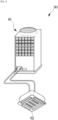
- an air conditioner 90 may include an outdoor unit 91 and an indoor unit 92.
- the outdoor unit 91 and the indoor unit 92 may be connected to each other through a pipe provided to allow a refrigerant to flow in the pipe.
- FIG. 1 illustrates the single outdoor unit 91
- the outdoor unit 91 may be provided in the plural.
- the outdoor unit 91 may perform both the heat pump cycle and the heat recovery cycle.
- FIG. 1 illustrates the single indoor unit 92
- the indoor unit 92 may be provided in the plural.
- the indoor unit 92 may be driven in cooling mode or heating mode.
- a heat exchange unit as will be described later may be provided in the outdoor unit 91 and/or the indoor unit 92.
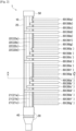
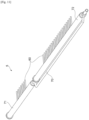
- FIG. 2 illustrates an overall structure of a distributor 1, according to a first embodiment of the disclosure.
- the distributor 1 is to distribute a refrigerant as an example of a fluid that passes in the distributor 1.
- the distributor 1 may include an outer pipe 10 in the form of a cylinder, an inner pipe 20 installed in the outer pipe 10, and an orifice plate 40 installed at a refrigerant upstream end of the inner pipe 20.
- the outer pipe 10 is shown as having the shape of a cylinder as an example, but it may have the form of a barrel, in which case the outer pipe 10 is an example of a barrel-shaped main pipe.
- the distributor 1 may include an inlet 30 e.g., welded to the refrigerant upstream end of the outer pipe 10 to guide the refrigerant, and a cap 50 e.g., welded to an end opposite to the refrigerant upstream end of the outer pipe 10.
- the inlet 30 is installed outside the orifice plate 40, so the orifice plate 40 is not visible from outside even though the orifice plate 40 is illustrated in FIG. 2 .
- the distributor 1 may include a plurality of branched pipes 60 fixed in the refrigerant downstream and connected to refrigerant pipes of a heat exchanger.
- FIG. 2 an internal structure of the inner pipe 20 is shown by removing the front of the outer pipe 10.
- a plurality of partition plates 21 are installed in the inner pipe 20, defining a plurality of distribution paths 22 accordingly.
- the plurality of partition plates 21 are installed in parallel with a center shaft of the inner pipe 20.
- partition plates 21a to 21c ends of the partition plates 21a to 21c on the side of the outer pipe 10, in particular
- distribution paths 22a to 22d are shown.
- the plurality of partition plates 21 are installed in parallel with the center shaft of the inner pipe 20, they may be installed along the shaft of the inner pipe 20, in which case, the plurality of partition plates 21 are an example of a plurality of partitions installed along the shaft of the main pipe.
- the orifice plate 40 may have a plurality of orifice holes 401 (see e.g., FIG. 9 ) through which to allow the refrigerant to flow into the plurality of distribution paths 22.
- the plurality of branched pipes 60 may be linked to the plurality of distribution paths 22.
- FIG. 2 shows the branched pipes 60e to 60g linked to distribution paths 22e to 22g, respectively, in addition to the branched pipes 60a to 60d linked to the distribution paths 22a to 22d, respectively.
- This structure may be understood as an example of a structure in which neighboring first and second branched pipes of the plurality of branched pipes are connected to first and second distribution paths of the plurality of distribution paths, the first and second distribution paths having one of the plurality of partitions in between them.
- the branched pipes 60a i.e. 60a, 60a', 60a
- 60b i.e. 60b, 60b', 60b
- the distribution paths 22a and 22b correspond to the first and second distribution paths
- the partition plate 21 a corresponds to the one of the plurality of partitions.
- the first and second branched pipes may not be adjacent to each other, and the first and second distribution paths may have at least one of the plurality of partitions in between them.
- the distribution paths 22a and 22c correspond to the first and second distribution paths and the partition plates 21a and 21b correspond to the at least one of the plurality of partitions.
- the branched pipe 60a may extend to the right directly from the distribution path 22a.
- the branched pipes 60b to 60d may extend forward from the distribution paths 22b to 22d first and then bend and extend to the right.
- the branched pipes 60e to 60g may extend to the opposite side from the distribution paths 22e to 22g first and then bend and extend to the right.
- branched pipes 60a to 60g There may be one set of branched pipes 60a to 60g, although in the first embodiment of the disclosure, there may be a multiple sets of branched pipes 60a (i.e. 60a, 60a', 60a") to 60g (i.e. 60g, 60g', 60g") installed in parallel.
- the structure as in the first embodiment of the disclosure may be understood as an example of a structure that includes at least two branched pipes connected to one of the plurality of distribution paths.
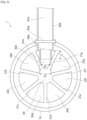
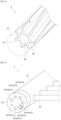
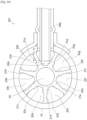
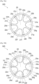
- FIG. 3 illustrates an A-A cross-sectional view of the distributor 1 of FIG. 2 .
- the partition plates 21a to 21g may be installed in the inner pipe 20, defining the plurality of distribution paths 22a to 22g accordingly.
- the partition plates 21 connect the outer side of the inner pipe 20 to the center portion of the inner pipe 20, so that the width of the distribution path 22 between the partition plates 21 decreases as it goes from the outer side to the center portion of the inner pipe 20.
- the branched pipe 60a linked and fixed to the distribution path 22a is inserted between the partition plates 21a and 21g that define the distribution path 22a.
- inner diameter Di of an axial part 62a differs among the multiple branched pipes 60a (three branched pipes 60a in FIG. 2 ).
- the axial part 62a may be a vena contracta portion 62a.
- insertion length L differs among the multiple branched pipes 60a (three branched pipes 60a, 60a', 60a" in FIG. 2 ).
- FIG. 3 is an A-A cross-sectional view of the distributor 1 of FIG.
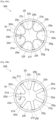
- FIG. 4 illustrates a first modification to the A-A cross-sectional view of the distributor 1 of FIG. 2 . While the axial part 62a of the branched pipe 60a has the shape that has an inclination from a main body 61a of the branched pipe 60a in FIG. 3 , it may have the straight form with a step from the main body 61a as shown in FIG. 4 to adjust flow of the refrigerant passage.
- the insertion length L of the branched pipe 60a is adjusted by installing a beading part 63a in FIGS. 3 and 4 , but is not be limited thereto.
- the insertion length L may be adjusted by outer diameter Do of the axial part 62a.
- the insertion length L of the branched pipe 60a may be determined by inserting the branched pipe 60a until the outer diameter Do of the axial part 62a fits the width between the partition plates 21a and 21g.
- FIGS. 5A to 5C illustrate second modifications to the A-A cross-sectional view of the distributor 1 of FIG. 2 .
- the cross-section of the distribution paths 22a to 22g may have the form of a trapezoid as shown in FIG. 5A , a triangle as shown in FIG. 5B , and a combination of trapezoid and rectangle as shown in FIG. 5C .
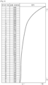
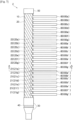
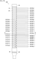
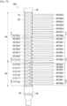
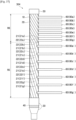
- FIG. 6 illustrates relations for each branched pipe 60 in a heat exchanger between wind velocity at the height of a refrigerant pipe connected to the branched pipe 60 and a refrigerant flow suitable to flow into the branched pipe 60.
- FIG. 6 it may be seen that at a higher height, wind velocity increases, so more refrigerant flow may be desirable.
- the inner diameter Di of the axial part 62 may be increased and the insertion length L of the branched pipe 60 may be reduced.
- 6 branched pipes 60 are each linked to 7 distribution paths 22, so that the refrigerant flows into a total of 42 branched pipes 60.
- one connected to a refrigerant pipe at a high height of the heat exchanger may have the axial part 62 with large inner diameter Di and have short insertion length L.
- one connected to a refrigerant pipe at a higher height of the heat exchanger may have the axial part 62 with large inner diameter Di and have short insertion length L.
- refrigerant pipes connected to the branched pipes 60 are arranged in parallel in the vertical direction of the heat exchanger, so the inner diameter of the axial part 62 and the insertion length L may differ depending on the location in the vertical direction of the heat exchanger, but it is not be limited thereto.
- the aforementioned structure may be understood as an example of a structure in which the inner diameter of the axial part of one of at least two branched pipes, through which a fluid distributed for a fast air flow portion of the heat exchanger passes is greater than the inner diameter of the axial part of the other branched pipe, through which a fluid distributed for a slow air flow portion of the heat exchanger passes.
- the aforementioned structure may be understood as an example of a structure in which the insertion length of one of at least two branched pipes to the distribution path, through which the fluid distributed for a fast air flow portion of the heat exchanger passes, is shorter than the insertion length of the other branched pipe to the distribution path, through which the fluid distributed for a slow air flow portion of the heat exchanger passes.
- both the inner diameter Di of the axial part 62 and the insertion length L differ among the plurality of branched pipes 60 in the first embodiment of the disclosure, it will not be limited thereto. At last one of the inner diameter of the axial part 62 or the insertion length L may differ among the plurality of branched pipes 60.
- FIG. 7 illustrates an overall structure of a distributor 2, according to a second embodiment of the disclosure.
- the distributor 2 is also to distribute a refrigerant as an example of a fluid that passes in the distributor 2.
- the distributor 2 may include the outer pipe 10 in the form of a cylinder, the inner pipe 20 installed in the outer pipe 10, and the orifice plate 40 installed at a refrigerant upstream end of the inner pipe 20.
- the outer pipe 10 is shown as having the shape of a cylinder as an example, but it may have the form of a barrel, in which case the outer pipe 10 is an example of a barrel-shaped main pipe.
- the distributor 2 may include the inlet 30 e.g., welded to the refrigerant upstream end of the outer pipe 10 to guide the refrigerant, and the cap 50 e.g., welded to an end opposite to the refrigerant upstream end of the outer pipe 10.
- the inlet 30 is installed outside the orifice plate 40, so the orifice plate 40 is not visible from outside even though the orifice plate 40 is illustrated in FIG. 7 .
- the distributor 2 may include a plurality of branched pipes 60 fixed in the refrigerant downstream and connected to refrigerant pipes of a heat exchanger.
- FIG. 7 an internal structure of the inner pipe 20 is shown by removing the front of the outer pipe 10.
- a plurality of partition plates 21 are installed in the inner pipe 20, defining a plurality of distribution paths 22 accordingly.
- the plurality of partition plates 21 are installed at a certain twisted angle to the center shaft of the inner pipe 20.
- partition plates 21a to 21g ends of the partition plates 21a to 21g on the side of the outer pipe 10, in particular
- distribution paths 22a to 22g are shown.
- the plurality of partition plates 21 are installed at a twisted angle to the center shaft of the inner pipe 20, they may also be said as being installed along the shaft of the inner pipe 20, in which case, the plurality of partition plates 21 are an example of a plurality of partitions installed along the shaft of the main pipe.
- the orifice plate 40 may have the plurality of orifice holes 401 (see e.g., FIG. 9 ) through which to allow the refrigerant to flow into the plurality of distribution paths 22.
- the plurality of branched pipes 60 may be linked to the plurality of distribution paths 22.
- FIG. 7 shows the branched pipes 60a (i.e. 60a, 60a", 60a") to 60g (i.e. 60g, 60g", 60g") linked to the distribution paths 22a to 22g, as the plurality of branched pipes 60.
- This structure may be understood as an example of a structure in which neighboring first and second branched pipes of the plurality of branched pipes are connected to first and second distribution paths of the plurality of distribution paths, the first and second distribution paths having one of the plurality of partitions in between them.
- the branched pipes 60a i.e. 60a, 60a', 60a
- 60b i.e. 60b, 60b', 60b
- the distribution paths 22a and 22b correspond to the first and second distribution paths
- the partition plate 21a corresponds to the one of the plurality of partitions.
- the first and second branched pipes may not be adjacent to each other, and the first and second distribution paths may have at least one of the plurality of partitions in between them.
- the distribution paths 22a and 22c correspond to the first and second distribution paths and the partition plates 21a and 21b correspond to the at least one of the plurality of partitions.
- the distribution paths 22a to 22g are defined to have a certain twisted angle to the center shaft of the inner pipe 20, so all the distribution paths 22a to 22g may turn around the inner pipe 20 once and pass through the right side of the inner pipe 20. Accordingly, the branched pipes 60a to 60g may all extend to the right by being linked to the portions at which the distribution paths 22a to 22g pass through the right side of the inner pipe 20.
- This structure may be understood as an example of a structure in which a plurality of partitions are installed to make a certain twisted angle to the shaft of the main pipe.
- branched pipes 60a to 60g There may be one set of branched pipes 60a to 60g, although in the second embodiment of the disclosure, there may be a multiple sets of branched pipes 60a (i.e. 60a, 60a', 60a") to 60g (i.e. 60g, 60g', 60ag') installed in parallel.
- the structure as in the second embodiment of the disclosure may be understood as an example of a structure that includes at least two branched pipes connected to one of the plurality of distribution paths.
- the A-A cross-sectional view of the distributor 2 of FIG. 7 is similar to what is shown in FIG. 3 .
- the inner diameter Di of the axial part 62a differs among the multiple branched pipes 60a (three branched pipes 60a, 60a', 60a" in FIG. 7 ).
- insertion length L differs among the multiple branched pipes 60a (three branched pipes 60a, 60a', 60a" in FIG. 7 ).
- FIG. 8 illustrates a partially enlarged view of the distributor 2, according to the second embodiment of the disclosure.
- the partition plates 21 are formed to have a twisted angle ⁇ to the center shaft of the inner pipe 20 between the outer pipe 10 and the inner pipe 20. Accordingly, centrifugal force of the refrigerant in the distribution path 22 may be changed, so that refrigerant flow distribution may be adjusted, thereby increasing heat exchange capability.
- a specific implementation in which the inner diameter Di of the axial part 62 and the insertion length L may differ among the plurality of branched pipes 60 may be considered to be the same as in the first embodiment.
- both the inner diameter Di of the axial part 62 and the insertion length L differ among the plurality of branched pipes 60 in the second embodiment of the disclosure, it will not be limited thereto.
- the inner diameter Di of the axial part 62 and the insertion length L of the branched pipe 60 may remain the same among the plurality of branched pipes 60.
- the distributor 3 is also to distribute a refrigerant as an example of a fluid that passes in the distributor 3.
- the distributor 3 may include the outer pipe 10 in the form of a cylinder, the inner pipe 20 installed in the outer pipe 10, and the orifice plate 40 installed at a refrigerant upstream end of the inner pipe 20.
- the outer pipe 10 is shown as having the shape of a cylinder as an example, but it may have the form of a barrel, in which case the outer pipe 10 is an example of a barrel-shaped main pipe.
- the distributor 3 may include a plurality of branched pipes 60 fixed in the refrigerant downstream and connected to refrigerant pipes of a heat exchanger.
- a plurality of partition plates 21 are installed in the inner pipe 20, defining a plurality of distribution paths 22 accordingly.
- FIG. 9 illustrates a partially enlarged view of the distributor 3, according to the second embodiment of the disclosure.
- the orifice plate 40 may have the plurality of orifice holes 401 through which to allow the refrigerant to flow into the plurality of distribution paths 22.
- the orifice holes 401 As the plurality of orifice holes 401, orifice holes 401a to 401g through which to allow the refrigerant to flow into the plurality of distribution paths 22a to 22g, respectively, are shown.
- the orifice holes 401a to 401g are an example of the plurality of orifice holes corresponding to the plurality of distribution paths.
- hole diameter Dh differs among the plurality of orifice holes 401. Accordingly, refrigerant flow distribution to the plurality of distribution paths 22 may be adjusted, thereby increasing heat exchange capability.
- Plate thickness of the orifice plate 40 may be equal to or greater than e.g., about 1 mm.
- the distributor 4 is also to distribute a refrigerant as an example of a fluid that passes in the distributor 4.
- the distributor 4 may include the outer pipe 10 in the form of a cylinder, the inner pipe 20 installed in the outer pipe 10, and the orifice plate 40 installed at a refrigerant upstream end of the inner pipe 20.
- the outer pipe 10 is shown as having the shape of a cylinder as an example, but it may have the form of a barrel, in which case the outer pipe 10 is an example of a barrel-shaped main pipe.
- the distributor 4 may include a plurality of branched pipes 60 fixed in the refrigerant downstream and connected to refrigerant pipes of a heat exchanger.
- a plurality of partition plates 21 are installed in the inner pipe 20, defining a plurality of distribution paths 22 accordingly.
- FIG. 10 illustrates an A-A cross-sectional view of the distributor 4 according to the fourth embodiment of the disclosure.
- the partition plates 21a to 21g may be installed in the inner pipe 20, defining the plurality of distribution paths 22a to 22g accordingly.
- the branched pipe 60a linked and fixed to the distribution path 22a is inserted between the partition plates 21a and 21g that define the distribution path 22a.
- the cross-sectional area differs among the plurality of distribution paths 22.
- This structure may be understood as an example of a structure in which a plurality of partitions define a plurality of distribution paths so that cross-sectional areas of the plurality of distribution paths cut across a particular plane may be different. Accordingly, refrigerant flow distribution to the plurality of distribution paths 22 may be adjusted, thereby increasing heat exchange capability.
- FIG. 11 illustrates a perspective view of a distributor 5, according to the fifth embodiment of the disclosure.
- the distributor 5 is split into a first distributor 71 and a second distributor 72.
- the first and second distributors 71 and 72 are an example of two distributor elements.
- the distributor 5 may include a pipe 70 to distribute the refrigerant to the second distributor 72 right before the refrigerant flows into the first distributor 71.
- the first and second distributors 71 and 72 are also to distribute a refrigerant as an example of a fluid that passes in the first and second distributors 71 and 72.
- the first and second distributors 71 and 72 may each include the outer pipe 10 in the form of a cylinder, the inner pipe 20 installed in the outer pipe 10, and the orifice plate 40 installed at a refrigerant upstream end of the inner pipe 20.
- the outer pipe 10 is shown as having the shape of a cylinder as an example, but it may have the form of a barrel, in which case the outer pipe 10 is an example of a barrel-shaped main pipe.
- the first and second distributors 71 and 72 may each include the plurality of branched pipes 60 fixed in the refrigerant downstream and connected to refrigerant pipes of a heat exchanger.
- a plurality of partition plates 21 are installed in the inner pipe 20, defining a plurality of distribution paths 22 accordingly.
- the distributor 5 is split into the first and second distributors 71 and 72. Accordingly, refrigerant flow distribution into the plurality of distribution paths 22 may be adjusted, thereby increasing heat exchange capability.
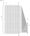
- FIG. 12 illustrates an overall structure of a heat exchange unit including a distributor 6 and a heat exchanger 8, according to a sixth embodiment of the disclosure.
- the distributor 6 is also to distribute a refrigerant as an example of a fluid that passes in the distributor 6.
- the distributor 6 may include the outer pipe 10 in the form of a cylinder, the inner pipe 20 installed in the outer pipe 10, and the orifice plate 40 installed at a refrigerant upstream end of the inner pipe 20.
- the outer pipe 10 is shown as having the shape of a cylinder as an example, but it may have the form of a barrel, in which case the outer pipe 10 is an example of a barrel-shaped main pipe.
- the distributor 6 may include the plurality of branched pipes 60 fixed in the refrigerant downstream and connected to refrigerant pipes of the heat exchanger.
- a plurality of partition plates 21 are installed in the inner pipe 20, defining a plurality of distribution paths 22 accordingly.
- the heat exchanger 8 included in the heat exchange unit in the sixth embodiment of the disclosure performs heat exchange between the refrigerant as an example of a fluid distributed by the distributor 6 and air.
- the heat exchanger 8 may include a plurality of fins 81 vertically arranged in parallel at preset intervals, a plurality of refrigerant pipes 82 installed in parallel to pass through holes of the fins 81, a header 83 at which the refrigerant flowing from each of the plurality of refrigerant pipes 82 joins, and an external connection pipe 84 through which to exhaust the refrigerant from the header 83.
- the plurality of branched pipes 60 of the distributor 6 may connect to the plurality of refrigerant pipes 82 of the heat exchanger 8 one to one.
- the height of the distributor 6 is lower than that of the heat exchanger 8.
- the distributor 6 having the structure as shown in FIG. 2 , this is possible by densely arranging the branched pipes 60 extending in parallel from the distributor 6.
- the distributor 6 having the structure as shown in FIG. 7 , this is possible by forming a large twisted angle between the plurality of partition plates 21 and the center shaft of the inner pipe 20, which enables the branched pipes 60 extending in parallel from the distributor 6 to be densely arranged. Accordingly, refrigerant flow distribution into the plurality of distribution paths 22 may be adjusted, thereby increasing heat exchange capability.
- the distributor 6 and the heat exchanger 8 may be compared in height because the distributor 6 and the heat exchanger 8 are installed to be long in the vertical direction, but the embodiments of the disclosure are not limited thereto.
- any comparison may be made as long as the length across which the branched pipes 60 of the distributor 6 are arranged in parallel and the length across which the refrigerant pipes 82 of the heat exchanger 8 are arranged in parallel may be compared with each other.
- a structure in which the height of the distributor 6 is lower than the height of the heat exchanger 8 is an example of a structure in which the length of the distributor is shorter than the length across which a plurality of fluid pipes in which a fluid distributed by a distributor of the heat exchanger flows are arranged in parallel.
- the distributor 7 is also to distribute a refrigerant as an example of a fluid that passes in the distributor 7.
- the distributor 7 may include the outer pipe 10 in the form of a cylinder, the inner pipe 20 installed in the outer pipe 10, and the orifice plate 40 installed at a refrigerant upstream end of the inner pipe 20.
- the outer pipe 10 is shown as having the shape of a cylinder as an example, but it may have the form of a barrel, in which case the outer pipe 10 is an example of a barrel-shaped main pipe.
- the distributor 7 may include the plurality of branched pipes 60 fixed in the refrigerant downstream and connected to refrigerant pipes of a heat exchanger.
- a plurality of partition plates 21 are installed in the inner pipe 20, defining a plurality of distribution paths 22 accordingly.
- FIG. 13 illustrates a partially enlarged view of the distributor 7, according to the seventh embodiment of the disclosure.
- the distributor 7 may also include the outer pipe 10, the inner pipe 20, and the orifice plate 40.
- a position fitting tool for fitting the plurality of distribution paths 22 into the plurality of orifice holes 401 may be installed.
- a convex portion 47 may be formed on the orifice plate 40 and a concave portion 27 may be formed on corresponding one of the plurality of partition plates 21.
- refrigerant flow distribution to the plurality of distribution paths 22 may be adjusted, thereby increasing heat exchange capability.
- FIG. 14 illustrates an overall structure of a distributor 101, according to an eighth embodiment of the disclosure.
- the distributor 101 is to distribute a refrigerant as an example of a fluid that passes in the distributor 101.
- the distributor 101 may include an outer pipe 10 in the form of a cylinder, and an inner pipe 20 installed in the outer pipe 10.
- the outer pipe 10 is shown as having the shape of a cylinder as an example, but it may have the form of a barrel, in which case the outer pipe 10 is an example of a barrel-shaped main pipe.
- FIG. 14 an internal structure of the inner pipe 20 is shown by removing the front of the outer pipe 10.
- a plurality of partition plates 21 are installed in the inner pipe 20, defining a plurality of distribution paths 22 accordingly.
- the plurality of partition plates 21 are installed in parallel with the center shaft of the inner pipe 20.
- partition plates 21a to 21c ends of the partition plates 21a to 21c on the side of the outer pipe 10, in particular
- distribution paths 22a to 22d are shown.
- the plurality of partition plates 21 are installed in parallel with the center shaft of the inner pipe 20, they may be installed along the shaft of the inner pipe 20, in which case, the plurality of partition plates 21 are an example of a plurality of partitions installed along the shaft of the main pipe.
- the outer pipe 10 and the inner pipe 20 are integrated in one unit. That is, the plurality of partition plates 21 are an example of a plurality of partitions installed integrally with the main pipe.
- the distributor 101 may include the inlet 30 e.g., welded to the refrigerant upstream end of the outer pipe 10 to guide the refrigerant, the orifice plate 40 installed at the refrigerant upstream end of the inner pipe 20, and the cap 50 e.g., welded to an end opposite to the refrigerant upstream end of the outer pipe 10.
- the inlet 30 is installed outside the orifice plate 40, so the orifice plate 40 is not visible from outside even though the orifice plate 40 is illustrated in FIG. 14 .
- the orifice plate 40 may have a plurality of orifice holes 411 (see FIG. 17 ) through which to allow the refrigerant to flow into the plurality of distribution paths 22.
- the cap 50 is to seal off all the plurality of distribution paths 22.
- the distributor 101 may include the plurality of branched pipes 60 fixed in the refrigerant downstream and connected to refrigerant pipes of a heat exchanger.
- the plurality of branched pipes 60 may be linked to the plurality of distribution paths 22.
- FIG. 14 shows the branched pipes 60e (i.e. 60e, 60e', 60e") to 60g (i.e. 60g, 60g', 60g") linked to distribution paths 22e to 22g, respectively, in addition to the branched pipes 60a (i.e. 60a, 60a', 60a") to 60d (i.e. 60d, 60d', 60d”) linked to the distribution paths 22a to 22d, respectively.
- This structure may be understood as an example of a structure in which neighboring first and second branched pipes of the plurality of branched pipes are connected to first and second distribution paths of the plurality of distribution paths, the first and second distribution paths having one of the plurality of partitions in between them.
- the distribution paths 22a and 22b correspond to the first and second distribution paths
- the partition plate 21a corresponds to the one of the plurality of partitions.
- the first and second branched pipes may not be adjacent to each other, and the first and second distribution paths may have at least one of the plurality of partitions in between them.
- the distribution paths 22a and 22c correspond to the first and second distribution paths and the partition plates 21a and 21b correspond to the at least one of the plurality of partitions.
- the branched pipe 60a may extend to the right directly from the distribution path 22a.
- the branched pipes 60b to 60d may extend forward from the distribution paths 22b to 22d first and then bend and extend to the right.
- the branched pipes 60e to 60g may extend to the opposite side from the distribution paths 22e to 22g first and then bend and extend to the right.
- branched pipes 60a to 60g There may be one set of branched pipes 60a to 60g, although in the eighth embodiment of the disclosure, there may be a multiple sets of branched pipes 60a, 60a', 60a" to 60g, 60g', 60g" installed in parallel.
- the structure as in the eighth embodiment of the disclosure may be understood as an example of a structure that includes at least two branched pipes connected to one of the plurality of distribution paths.
- FIG. 15 illustrates an A-A cross-sectional view of the distributor 101 of FIG. 14 .
- the outer pipe 10 and the inner pipe 20 are integrated in one unit.
- the partition plates 21a to 21g may be installed in the inner pipe 20, defining the plurality of distribution paths 22a to 22g accordingly.
- the partition plates 21 connect the outer pipe 10 and the center portion of the inner pipe 20, so that the width of the distribution path 22 between the partition plates 21 decreases as it goes from the outer side of the inner pipe 20 to the center portion.
- the branched pipe 60a linked and fixed to the distribution path 22a is inserted between the partition plates 21a and 21g that define the distribution path 22a.
- the inner diameter Di of the axial part 62a differs among the multiple branched pipes 60a (three branched pipes 60a in FIG. 14 ).
- insertion length L differs among the multiple branched pipes 60a (three branched pipes 60a in FIG. 14 ).
- FIG. 15 is an A-A cross-sectional view of the distributor 101 of FIG. 14 , what are described above in connection with the branched pipe 60a may be equally applied to the other branched pipes 60b to 60g linked to the distribution paths 22a to 22g.
- both the inner diameter Di of the axial part 62 and the insertion length L differ among the plurality of branched pipes 60 in the eighth embodiment of the disclosure, it will not be limited thereto. At last one of the inner diameter of the axial part 62 or the insertion length L may differ among the plurality of branched pipes 60.
- the refrigerant flow resistance is changed in the single distribution path 22 while the outer pipe 10 and the inner pipe 20 are integrated in one unit. Accordingly, refrigerant flow distribution may be adjusted while preventing a refrigerant leak, thereby increasing heat exchange capability.
- FIG. 16 illustrates an overall structure of a distributor 102, according to a ninth embodiment of the disclosure.
- the distributor 102 is also to distribute a refrigerant as an example of a fluid that passes in the distributor 102.
- the distributor 102 may include an outer pipe 10 in the form of a cylinder, and an inner pipe 20 installed in the outer pipe 10.
- the outer pipe 10 is shown as having the shape of a cylinder as an example, but it may have the form of a barrel, in which case the outer pipe 10 is an example of a barrel-shaped main pipe.
- FIG. 16 an internal structure of the inner pipe 20 is shown by removing the front of the outer pipe 10.
- a plurality of partition plates 21 are installed in the inner pipe 20, defining a plurality of distribution paths 22 accordingly.
- the plurality of partition plates 21 are installed at a twisted angle to the center shaft of the inner pipe 20.
- partition plates 21a to 21g ends of the partition plates 21a to 21g on the side of the outer pipe 10, in particular
- distribution paths 22a to 22g are shown.
- the plurality of partition plates 21 are installed at a twisted angle to the center shaft of the inner pipe 20, they may also be said as being installed along the shaft of the inner pipe 20, in which case, the plurality of partition plates 21 are an example of a plurality of partitions installed along the shaft of the main pipe.
- the outer pipe 10 and the inner pipe 20 are integrated in one unit. That is, the plurality of partition plates 21 are an example of a plurality of partitions installed integrally with the main pipe.
- the distributor 102 may include the inlet 30 e.g., welded to the refrigerant upstream end of the outer pipe 10 to guide the refrigerant, the orifice plate 40 installed at the refrigerant upstream end of the inner pipe 20, and the cap 50 e.g., welded to an end opposite to the refrigerant upstream end of the outer pipe 10.
- the inlet 30 is installed outside the orifice plate 40, so the orifice plate 40 is not visible from outside even though the orifice plate 40 is illustrated in FIG. 14 .
- the orifice plate 40 may have a plurality of orifice holes 411 (see FIG. 17 ) through which to allow the refrigerant to flow into the plurality of distribution paths 22.
- the cap 50 is to seal off all the plurality of distribution paths 22.
- the distributor 102 may include the plurality of branched pipes 60 fixed in the refrigerant downstream and connected to refrigerant pipes of a heat exchanger.
- the plurality of branched pipes 60 may be linked to the plurality of distribution paths 22.
- FIG. 16 shows the branched pipes 60a to 60g linked to the distribution paths 22a to 22g, as the plurality of branched pipes 60.
- This structure may be understood as an example of a structure in which neighboring first and second branched pipes of the plurality of branched pipes are connected to first and second distribution paths of the plurality of distribution paths, the first and second distribution paths having one of the plurality of partitions in between them.
- the branched pipes 60a i.e. 60a, 60a', 60a
- 60b i.e. 60b, 60b', 60b
- the distribution paths 22a and 22b correspond to the first and second distribution paths
- the partition plate 21a corresponds to the one of the plurality of partitions.
- the first and second branched pipes may not be adjacent to each other, and the first and second distribution paths may have at least one of the plurality of partitions in between them.
- the distribution paths 22a and 22c correspond to the first and second distribution paths and the partition plates 21a and 21b correspond to the at least one of the plurality of partitions.
- the distribution paths 22a to 22g are defined to have a certain twisted angle to the center shaft of the inner pipe 20, so all the distribution paths 22a to 22g may turn around the inner pipe 20 once and pass through the right side of the inner pipe 20. Accordingly, the branched pipes 60a to 60g may all extend to the right by being linked to the portions at which the distribution paths 22a to 22g pass through the right side of the inner pipe 20.
- This structure may be understood as an example of a structure in which a plurality of partitions are installed to make a certain twisted angle to the shaft of the main pipe.
- branched pipes 60a to 60g There may be one set of branched pipes 60a to 60g, although in the ninth embodiment of the disclosure, there may be a multiple sets of branched pipes 60a, 60a', 60a" to 60g, 60g', 60g" installed in parallel.
- the structure as in the ninth embodiment of the disclosure may be understood as an example of a structure that includes at least two branched pipes connected to one of the plurality of distribution paths.
- the A-A cross-sectional view of the distributor 102 of FIG. 16 is similar to what is shown in FIG. 15 .
- the inner diameter Di of the axial part 62a differs among the multiple branched pipes 60a (three branched pipes 60a in FIG. 16 ).
- insertion length L differs among the multiple branched pipes 60a (three branched pipes 60a, 60a', 60a" in FIG. 16 ). The same is true of the branched pipes 60b to 60g linked to the distribution paths 22b to 22g.
- both the inner diameter Di of the axial part 62 and the insertion length L differ among the plurality of branched pipes 60 in the ninth embodiment of the disclosure, it will not be limited thereto. At last one of the inner diameter of the axial part 62 or the insertion length L may differ among the plurality of branched pipes 60.
- the refrigerant flow resistance is changed in the single distribution path 22 while the outer pipe 10 and the inner pipe 20 are integrated in one unit. Accordingly, refrigerant flow distribution may be adjusted while preventing a refrigerant leak, thereby increasing heat exchange capability.
- the distributor 103 is also to distribute a refrigerant as an example of a fluid that passes in the distributor 103.
- the distributor 103 may include an outer pipe 10 in the form of a cylinder, and an inner pipe 20 installed in the outer pipe 10.
- the outer pipe 10 is shown as having the shape of a cylinder as an example, but it may have the form of a barrel, in which case the outer pipe 10 is an example of a barrel-shaped main pipe.
- a plurality of partition plates 21 are installed in the inner pipe 20, defining a plurality of distribution paths 22 accordingly.
- the outer pipe 10 and the inner pipe 20 are integrated in one unit. That is, the plurality of partition plates 21 are an example of a plurality of partitions installed integrally with the main pipe.
- the distributor 103 may include the inlet 30 e.g., welded to the refrigerant upstream end of the outer pipe 10 to guide the refrigerant, the orifice plate 40 installed at the refrigerant upstream end of the inner pipe 20, and the cap 50 e.g., welded to an end opposite to the refrigerant upstream end of the outer pipe 10.
- the distributor 103 may include the plurality of branched pipes 60 fixed in the refrigerant downstream and connected to refrigerant pipes of a heat exchanger.
- FIG. 17 illustrates a partially enlarged view of the distributor 103, according to the tenth embodiment of the disclosure.
- the orifice plate 40 corresponds to a projected orifice plate 41
- a brazing sheet 42 is installed between the projected orifice plate 41 and the outer pipe 10.
- the projected orifice plate 41 may have a plurality of orifice holes 411 through which to allow the refrigerant to flow into the plurality of distribution paths 22.
- the plurality of orifice holes 411 may include orifice holes 411a to 411g through which to allow the refrigerant to flow into the plurality of distribution paths 22a to 22g, respectively.
- the projected orifice plate 41 may also include a plurality of projections 412 to be inserted to the plurality of distribution paths 22.
- the plurality of projections 412 may include projections 412a to 412g to be inserted to the distribution paths 22a to 22g, respectively.
- Each of the plurality of projections 412 may have a through hole in the center, through which to allow the refrigerant flowing from the corresponding orifice hole 411 to flow into the corresponding distribution path 22.
- the brazing sheet 42 serves to bond the plurality of projections 412 of the projected orifice plate 41 tightly to the plurality of distribution paths 22 of the outer pipe 10 when the plurality of projections 412 of the projected orifice plate 41 are inserted to the plurality of distribution paths 22 of the outer pipe 10.
- the brazing sheet 42 may include a plurality of sheet holes 421 to which the plurality of projections 412 are inserted.
- the brazing sheet 42 may also include a plurality of projections 422 to be inserted to the plurality of distribution paths 22.
- Each of the plurality of projections 422 may have a through hole in the center, through which to allow the refrigerant flowing from the corresponding sheet hole 421 to flow into the corresponding distribution path 22.
- brazing sheet 42 may be applied to a bonding portion between the projected orifice plate 41 and the outer pipe 10 when the plurality of projections 412 of the projected orifice plate 41 are inserted to the plurality of distribution paths 22 of the outer pipe 10.
- the orifice plate 40 is provided as the projected orifice plate 41 with projections 412 to be inserted to the plurality of distribution paths 22. Accordingly, refrigerant flow distribution may be adjusted while preventing a refrigerant leak from the bonding portion between the orifice plate 40 and the outer pipe 10, thereby increasing heat exchange capability.
- the distributor 104 is also to distribute a refrigerant as an example of a fluid that passes in the distributor 104.
- the distributor 104 may include an outer pipe 10 in the form of a cylinder, and an inner pipe 20 installed in the outer pipe 10.
- the outer pipe 10 is shown as having the shape of a cylinder as an example, but it may have the form of a barrel, in which case the outer pipe 10 is an example of a barrel-shaped main pipe.
- a plurality of partition plates 21 are installed in the inner pipe 20, defining a plurality of distribution paths 22 accordingly.
- the outer pipe 10 and the inner pipe 20 are integrated in one unit. That is, the plurality of partition plates 21 are an example of a plurality of partitions installed integrally with the main pipe.
- the distributor 104 may include the inlet 30 e.g., welded to the refrigerant upstream end of the outer pipe 10 to guide the refrigerant, the orifice plate 40 installed at the refrigerant upstream end of the inner pipe 20, and the cap 50 e.g., welded to an end opposite to the refrigerant upstream end of the outer pipe 10.
- the distributor 104 may include the plurality of branched pipes 60 fixed in the refrigerant downstream and connected to refrigerant pipes of a heat exchanger.
- FIG. 18 illustrates a partially enlarged view of the distributor 104, according to the eleventh embodiment of the disclosure.
- the cap 50 corresponds to a projected cap 51
- a brazing sheet 52 is installed between the projected cap 51 and the outer pipe 10.
- the projected cap 51 may also include a plurality of projections 512 to be inserted to the plurality of distribution paths 22.
- the plurality of projections 512 may include projections 512a to 512g to be inserted to the distribution paths 22a to 22g, respectively.
- the plurality of projections 512 are hidden in the cap 50 and not visible at an angle as in FIG. 18 , but they are represented in dashed lines as if seen through the cap 50.
- the brazing sheet 52 serves to bond the plurality of projections 512 of the projected cap 51 tightly to the plurality of distribution paths 22 of the outer pipe 10 when the plurality of projections 512 of the projected cap 51 are inserted to the plurality of distribution paths 22 of the outer pipe 10.
- the brazing sheet 52 may include a plurality of sheet holes 521 to which the plurality of projections 512 are inserted.
- the brazing sheet 52 may also include a plurality of projections 522 to be inserted to the plurality of distribution paths 22.
- brazing sheet 52 may be applied to a bonding portion between the projected cap 51 and the outer pipe 10 when the plurality of projections 512 of the projected cap 51 are inserted to the plurality of distribution paths 22 of the outer pipe 10.
- the cap 50 may be provided as the projected cap 51 with the projections 512 to be inserted to the plurality of distribution paths 22. Accordingly, refrigerant flow distribution may be adjusted while preventing a refrigerant leak from the bonding portion between the cap 50 and the outer pipe 10, thereby increasing heat exchange capability.
- the distributor 105 is also to distribute a refrigerant as an example of a fluid that passes in the distributor 105.
- the distributor 105 may include an outer pipe 10 in the form of a cylinder, and an inner pipe 20 installed in the outer pipe 10.
- the outer pipe 10 is shown as having the shape of a cylinder as an example, but it may have the form of a barrel, in which case the outer pipe 10 is an example of a barrel-shaped main pipe.
- a plurality of partition plates 21 are installed in the inner pipe 20, defining a plurality of distribution paths 22 accordingly.
- the outer pipe 10 and the inner pipe 20 are integrated in one unit. That is, the plurality of partition plates 21 are an example of a plurality of partitions installed integrally with the main pipe.
- the distributor 105 may include the inlet 30 e.g., welded to the refrigerant upstream end of the outer pipe 10 to guide the refrigerant, the orifice plate 40 installed at the refrigerant upstream end of the inner pipe 20, and the cap 50 e.g., welded to an end opposite to the refrigerant upstream end of the outer pipe 10.
- the distributor 105 may include the plurality of branched pipes 60 fixed in the refrigerant downstream and connected to refrigerant pipes of a heat exchanger.
- FIG. 19 illustrates a perspective view of an exterior cover 12, according to the twelfth embodiment of the present disclosure.
- the exterior cover 12 may include a plurality of burring holes 13.
- the plurality of branched pipes 60 may be connected to the exterior cover 12 by being inserted to the plurality of burring holes 13, respectively.
- the exterior cover 12 as used herein is an example of a cover mounted on the outer circumference of the main pipe.
- FIG. 20 illustrates a partially enlarged view of the distributor 105, according to the twelfth embodiment of the disclosure.
- the branched pipes 60 is connected from one direction, so that the single exterior cover 12 may be attached to the outer pipe 10.
- the branched pipes 60 are connected from multiple directions.
- the outer pipe 10 as shown in FIG. 20 has an exterior cover 12a with burring holes 13a and an exterior cover 12b with burring holes 13b attached to the outer pipe 10 to face different directions.
- the exterior cover 12a may be fixed to the outer pipe 10 by bending a catch 14a at its end in a direction as indicated by an arrow Da, as shown in FIG. 20 .
- the exterior cover 12b may be fixed to the outer pipe 10 by bending a catch 14b at its end in a direction as indicated by an arrow Db.
- the exterior covers 12a and 12b may be fixed to the outer pipe 10 by wrapping a steel line around the outer pipe 10 and exterior covers 12a and 12b altogether while attaching the exterior covers 12a and 12b to the outer pipe 10.
- exterior covers 12 Although there are two exterior covers 12 attached to the outer pipe 10 in FIG. 20 , three or more exterior covers 12 may be attached to the outer pipe 10.
- burring holes 13 are formed at the exterior cover 12 to attach the exterior cover 12 to the outer pipe 10, the disclosure is not limited thereto.
- the burring holes 13 may be formed right at the outer pipe 10.
- the plurality of branched pipes 60 are inserted to the plurality of burring holes 13. Accordingly, refrigerant flow distribution may be adjusted while preventing a refrigerant leak from the bonding portion between the branched pipes 60 and the outer pipe 10, thereby increasing heat exchange capability.
- FIG. 21 illustrates an overall structure of a heat exchange unit including a distributor 106 and the heat exchanger 8, according to a thirteenth embodiment of the disclosure.
- the distributor 106 is also to distribute a refrigerant as an example of a fluid that passes in the distributor 106.
- the distributor 106 may include an outer pipe 10 in the form of a cylinder, and an inner pipe 20 installed in the outer pipe 10.
- the outer pipe 10 is shown as having the shape of a cylinder as an example, but it may have the form of a barrel, in which case the outer pipe 10 is an example of a barrel-shaped main pipe.
- a plurality of partition plates 21 are installed in the inner pipe 20, defining a plurality of distribution paths 22 accordingly.
- the outer pipe 10 and the inner pipe 20 are integrated in one unit. That is, the plurality of partition plates 21 are an example of a plurality of partitions installed integrally with the main pipe.
- the distributor 106 may include the inlet 30 e.g., welded to the refrigerant upstream end of the outer pipe 10 to guide the refrigerant, the orifice plate 40 installed at the refrigerant upstream end of the inner pipe 20, and the cap 50 e.g., welded to an end opposite to the refrigerant upstream end of the outer pipe 10.
- the distributor 106 may include the plurality of branched pipes 60 fixed in the refrigerant downstream and connected to refrigerant pipes 82 of the heat exchanger 8 as will be described later.
- the heat exchanger 8 included in the heat exchange unit in the thirteenth embodiment of the disclosure performs heat exchange between the refrigerant as an example of a fluid distributed by the distributor 106 and air.
- the heat exchanger 8 may include a plurality of fins 81 vertically arranged in parallel at preset intervals, a plurality of refrigerant pipes 82 as an example of a plurality of fluid pipes installed in parallel to pass through holes of the fins 81, a header 83 at which the refrigerant flowing from each of the plurality of refrigerant pipes 82 joins, and an external connection pipe 84 through which to exhaust the refrigerant from the header 83.
- the plurality of branched pipes 60 of the distributor 106 may connect to the plurality of refrigerant pipes 82 of the heat exchanger 8 one to one.
- the refrigerant flow resistance is changed in the single distribution path 22 while the outer pipe 10 and the inner pipe 20 are integrated in one unit. Accordingly, refrigerant flow distribution may be adjusted while preventing a refrigerant leak, thereby increasing heat exchange capability.
- FIG. 22 illustrates an overall structure of a distributor 201, according to a fourteenth embodiment of the disclosure.
- the distributor 201 is to distribute a refrigerant as an example of a fluid that passes in the distributor 201.
- the distributor 201 may include an outer pipe 10 in the form of a cylinder, an inner pipe 20 installed in the outer pipe 10, and an orifice plate 40 installed at a refrigerant upstream end of the inner pipe 20.
- the outer pipe 10 is shown as having the shape of a cylinder as an example, but it may have the form of a barrel, in which case the outer pipe 10 is an example of a barrel-shaped main pipe.
- the distributor 201 may include the inlet 30 e.g., welded to the refrigerant upstream end of the outer pipe 10 to guide the refrigerant, and the cap 50 e.g., welded to an end opposite to the refrigerant upstream end of the outer pipe 10.
- the inlet 30 is installed outside the orifice plate 40, so the orifice plate 40 is not visible from outside even though the orifice plate 40 is illustrated in FIG. 22 .
- the distributor 201 may include a plurality of branched pipes 60 fixed in the refrigerant downstream and connected to refrigerant pipes of a heat exchanger.
- FIG. 22 an internal structure of the inner pipe 20 is shown by removing the front of the outer pipe 10.
- a plurality of partition plates 21 are installed in the inner pipe 20, defining a plurality of distribution paths 22 accordingly.
- the plurality of partition plates 21 are installed in parallel with the center shaft of the inner pipe 20.
- FIG. 22 as viewed from the front, of the plurality of partition plates 21, partition plates 21a to 21c (ends of the partition plates 21a to 21c on the side of the outer pipe 10, in particular) are shown, and of the plurality of distribution paths 22, distribution paths 22a to 22d are shown.
- the plurality of partition plates 21 are installed in parallel with the center shaft of the inner pipe 20, they may be installed along the shaft of the inner pipe 20, in which case, the plurality of partition plates 21 are an example of a plurality of partitions installed along the shaft of the main pipe.
- the orifice plate 40 may have a plurality of orifice holes through which to allow the refrigerant to flow into the plurality of distribution paths 22.
- the plurality of branched pipes 60 may be linked to the plurality of distribution paths 22.
- FIG. 22 shows the branched pipes 60e (i.e. 60e, 60e', 60e") to 60g (i.e. 60g, 60g', 60g") linked to distribution paths 22e to 22g, respectively, in addition to the branched pipes 60a (i.e. 60a, 60a', 60a") to 60d (i.e. 60d, 60d', 60d") linked to the distribution paths 22a to 22d, respectively.
- This structure may be understood as an example of a structure in which neighboring first and second branched pipes of the plurality of branched pipes are connected to first and second distribution paths of the plurality of distribution paths, the first and second distribution paths having one of the plurality of partitions in between them.
- the distribution paths 22a and 22b correspond to the first and second distribution paths
- the partition plate 21a corresponds to the one of the plurality of partitions.
- the first and second branched pipes may not be adjacent to each other, and the first and second distribution paths may have at least one of the plurality of partitions in between them.
- the distribution paths 22a and 22c correspond to the first and second distribution paths and the partition plates 21a and 21b correspond to the at least one of the plurality of partitions.
- the branched pipe 60a may extend to the right directly from the distribution path 22a.
- the branched pipes 60b to 60d may extend forward from the distribution paths 22b to 22d first and then bend and extend to the right.
- the branched pipes 60e to 60g may extend to the opposite side from the distribution paths 22e to 22g first and then bend and extend to the right.
- branched pipes 60a to 60g There may be one set of branched pipes 60a to 60g, although in the fourteenth embodiment of the disclosure, there may be a multiple sets of branched pipes 60a, 60a', 60a" to 60g, 60g', 60g" installed in parallel.
- the structure as in the fourteenth embodiment of the disclosure may be understood as an example of a structure that includes at least two branched pipes connected to one of the plurality of distribution paths.
- FIGS. 23 to 25 are cross-sectional views along line A-A of the distributor 201 of FIG. 22 .
- the partition plates 21a to 21g may be installed in the inner pipe 20, defining the plurality of distribution paths 22a to 22g accordingly.
- the partition plates 21 connect the outer pipe 10 and the center portion of the inner pipe 20, so that the width of the distribution path 22 between the partition plates 21 decreases as it goes from the outer side of the inner pipe 20 to the center portion.
- Step parts 23a to 23g may be formed on each of the partition plates 21a to 21g.
- the branched pipe 60a linked and fixed to the distribution path 22a is inserted between the partition plates 21a and 21g that define the distribution path 22a and supported by the step parts 23a and 23g.
- the distribution path 22a corresponds to a distribution path defined by the two partitions
- the branched pipe 60a corresponds to a branched pipe connected to a distribution path among the plurality of branched pipes
- the step parts 23a and 23g corresponds to at least one step part that supports the branched pipe.
- the step parts 23a to 23g each include two steps without being limited thereto.
- the step parts 23a to 23g may each include one step or three or more steps.
- the branched pipe 60a may be put in until reaching the second or outer steps of the step parts 23a and 23g from the center portion of the inner pipe 20. This makes a step on the side of the refrigerant inlet of the branched pipe 60, which enables changing of fluid resistance of the refrigerant and adjustment of refrigerant flow distribution.
- differing the position of steps of the step parts 23a and 23g supporting the branched pipe 60a may differ the inner diameter D of the axial part 62a.
- This structure is an example of a structure in which the inner diameter of the axial part differs as the branched pipe is supported by different ones of the plurality of steps.
- differing the position of steps of the step parts 23a and 23g to support the branched pipe 60a may differ the insertion length L of the branched pipe 60a as illustrated in FIG. 24 .
- This structure is an example of a structure in which the insertion length to the distribution path differs as the branched pipe is supported by different ones of the plurality of steps.
- the insertion length L of the branched pipe 60a may be set to be less than half of depth H of the distribution path 22a.
- the step parts 23a to 23g may include steps at positions further outside the half of the depth H of the distribution paths 22a to 22g to support the branched pipe 60a.
- FIG. 26 illustrates a graph representing a reason why it is desirable to have the insertion length L of a branched pipe 60 be less than half the depth H of the distribution path 22.
- the horizontal axis represents insertion length tolerance.
- the insertion length tolerance represents positive errors toward shorter insertion length L and negative errors toward longer insertion length L based on the half of the depth H. It may be seen from the graph that when the insertion length L is long, the percentage of flow distribution rapidly changes for the deviation of the insertion length tolerance, and that when the insertion length L is short, the percentage of flow distribution is slowly changed and stable for the deviation of the insertion length tolerance. Hence, it is desirable to have the insertion length L of the branched pipe 60 be less than half the depth H of the distribution path 22.
- the structure herein is an example of a structure of having the insertion length to the distribution path be less than half the depth of the distribution path by supporting the branched pipe by particular steps at shallow positions not deeper than half the depth of the distribution path.
- the particular steps may correspond to the steps further outside the half of the depth H of the distribution paths 22a to 22b.
- FIGS. 23 to 25 are A-A cross-sectional views of the distributor 201 of FIG. 22 , what are described above in connection with the branched pipe 60a may be equally applied to the other branched pipes 60b to 60g linked to the distribution paths 22a to 22g.
- the inner diameter D of the axial part of the branched pipes 60 or the insertion length L of the branched pipes 60 differs among the plurality of branched pipes 60, or the insertion length L of the branched pipes 60 may be set to be less than half the depth H of the distribution path 22. Accordingly, refrigerant flow distribution may be adjusted, thereby increasing heat exchange capability.
- FIG. 27 illustrates an A-A cross-sectional view of the distributor 201 of FIG. 22 .
- the partition plates 21a to 21g may be installed in the inner pipe 20, defining the plurality of distribution paths 22a to 22g accordingly.
- the partition plates 21 connect the outer pipe 10 and the center portion of the inner pipe 20, so that the width of the distribution path 22 between the partition plates 21 decreases as it goes from the outer side of the inner pipe 20 to the center portion.
- Step parts 23a to 23g may be formed on each of the partition plates 21a to 21g.
- the branched pipe 60a linked and fixed to the distribution path 22a is inserted between the partition plates 21a and 21g that define the distribution path 22a and supported by the step parts 23a and 23g.
- the distribution path 22a corresponds to a distribution path defined by the two partitions
- the branched pipe 60a corresponds to a branched pipe connected to a distribution path among the plurality of branched pipes
- the step parts 23a and 23g corresponds to at least one step part that supports the branched pipe.
- the step parts 23a to 23g each include a step without being limited thereto.
- the step parts 23a to 23g may each include two or more steps.
- a refrigerant inflow area S1 at the front end of the branched pipe 60a that occupies a portion further inside than the steps of the step parts 23a and 23g supporting the branched pipe 60a may be different from a refrigerant passing area S2 around the branched pipe 60a that occupies a portion further outside than the steps supporting the branched pipe 60a.
- changes in ratio between the refrigerant inflow area S1 at the front end of the branched pipe 60a and the refrigerant passing area S2 around the branched pipe 60a may enable adjustment of the refrigerant flow distribution, thereby increasing the heat exchange capability.
- FIG. 27 is an A-A cross-sectional view of the distributor 201 of FIG. 22 , what are described above in connection with the branched pipe 60a may be equally applied to the other branched pipes 60b to 60g linked to the distribution paths 22a to 22g.
- FIG. 28 illustrates an overall structure of a distributor 202, according to a fifteenth embodiment of the disclosure.
- the distributor 202 is also to distribute a refrigerant as an example of a fluid that passes in the distributor 202.
- the distributor 202 may include an outer pipe 10 in the form of a cylinder, an inner pipe 20 installed in the outer pipe 10, and an orifice plate 40 installed at a refrigerant upstream end of the inner pipe 20.
- the outer pipe 10 is shown as having the shape of a cylinder as an example, but it may have the form of a barrel, in which case the outer pipe 10 is an example of a barrel-shaped main pipe.
- the distributor 202 may include the inlet 30 e.g., welded to the refrigerant upstream end of the outer pipe 10 to guide the refrigerant, and the cap 50 e.g., welded to an end opposite to the refrigerant upstream end of the outer pipe 10.
- the inlet 30 is installed outside the orifice plate 40, so the orifice plate 40 is not visible from outside even though the orifice plate 40 is illustrated in FIG. 22 .
- the distributor 202 may include a plurality of branched pipes 60 fixed in the refrigerant downstream and connected to refrigerant pipes of a heat exchanger.
- FIG. 28 an internal structure of the inner pipe 20 is shown by removing the front of the outer pipe 10.
- a plurality of partition plates 21 are installed in the inner pipe 20, defining a plurality of distribution paths 22 accordingly.
- the plurality of partition plates 21 are installed at a twisted angle to the center shaft of the inner pipe 20.
- partition plates 21a to 21g ends of the partition plates 21a to 21g on the side of the outer pipe 10, in particular
- distribution paths 22a to 22g are shown.
- the plurality of partition plates 21 are installed at a twisted angle to the center shaft of the inner pipe 20, they may also be said as being installed along the shaft of the inner pipe 20, in which case, the plurality of partition plates 21 are an example of a plurality of partitions installed along the shaft of the main pipe.
- the orifice plate 40 may have a plurality of orifice holes through which to allow the refrigerant to flow into the plurality of distribution paths 22.
- the plurality of branched pipes 60 may be linked to the plurality of distribution paths 22.
- the branched pipes 60a to 60g linked to the distribution paths 22a to 22g are shown as the plurality of branched pipes 60.
- This structure may be understood as an example of a structure in which neighboring first and second branched pipes of the plurality of branched pipes are connected to first and second distribution paths of the plurality of distribution paths, the first and second distribution paths having one of the plurality of partitions in between them.
- the branched pipes 60a i.e. 60a, 60a', 60a
- 60b i.e. (i.e. 60a, 60a', 60a"
- the distribution paths 22a and 22b correspond to the first and second distribution paths
- the partition plate 21a corresponds to the one of the plurality of partitions.
- the first and second branched pipes may not be adjacent to each other, and the first and second distribution paths may have at least one of the plurality of partitions in between them.
- the distribution paths 22a and 22c correspond to the first and second distribution paths and the partition plates 21a and 21b correspond to the at least one of the plurality of partitions.
- the distribution paths 22a to 22g are defined to have a certain twisted angle to the center shaft of the inner pipe 20, so all the distribution paths 22a to 22g may turn around the inner pipe 20 once and pass through the right side of the inner pipe 20. Accordingly, the branched pipes 60a to 60g may all extend to the right by being linked to the portions at which the distribution paths 22a to 22g pass through the right side of the inner pipe 20.
- This structure may be understood as an example of a structure in which a plurality of partitions are installed to make a certain twisted angle to the shaft of the main pipe.
- branched pipes 60a to 60g there may be one set of branched pipes 60a to 60g, although in the fifteenth embodiment of the disclosure, there may be a multiple sets of branched pipes 60a (i.e. 60a, 60a', 60a") to 60g (i.e. 60g, 60g', 60g") installed in parallel.
- the structure as in the fifteenth embodiment of the disclosure may be understood as an example of a structure that includes at least two branched pipes connected to one of the plurality of distribution paths.
- the A-A cross-sectional view of the distributor 202 of FIG. 28 is similar to what is shown in FIGS. 23 to 25 .
- differing the position of steps of the step parts 23a and 23g supporting the branched pipe 60a may differ the inner diameter D of the vena contracta 62a.
- This structure is an example of a structure in which the inner diameter of the axial part differs as the branched pipe is supported by different ones of the plurality of steps.
- differing the position of steps of the step parts 23a and 23g supporting the branched pipe 60a may differ the insertion length L of the branched pipe 60a.
- This structure is an example of a structure in which the insertion length to the distribution path differs as the branched pipe is supported by different ones of the plurality of steps.
- the insertion length L of the branched pipe 60a may be set to be less than half of the depth H of the distribution path 22a.
- the structure herein is an example of a structure of having the insertion length to the distribution path be less than half of the depth of the distribution path by supporting the branched pipe by particular steps at shallow positions not deeper than half the depth of the distribution path.
- the same is true of the branched pipes 60b to 60g linked to the distribution paths 22b to 22g.
- the inner diameter D of the axial part of the branched pipes 60 or the insertion length L of the branched pipes 60 differs among the plurality of branched pipes 60, or the insertion length L of the branched pipes 60 may be set to be less than half the depth H of the distribution path 22. Accordingly, refrigerant flow distribution may be adjusted, thereby increasing heat exchange capability.
- a refrigerant inflow area S1 at the front end of the branched pipe 60a that occupies a portion further inside than the steps of the step parts 23a and 23g supporting the branched pipe 60a may be different from a refrigerant passing area S2 around the branched pipe 60a that occupies a portion further outside than the steps supporting the branched pipe 60a.
- changes in ratio between the refrigerant inflow area S1 at the front end of the branched pipe 60a and the refrigerant passing area S2 around the branched pipe 60a may enable adjustment of the refrigerant flow distribution, thereby increasing the heat exchange capability.
- the branched pipes 60b to 60g linked to the distribution paths 22b to 22g may enable adjustment of the refrigerant flow distribution, thereby increasing the heat exchange capability.
- the distributor 203 is also to distribute a refrigerant as an example of a fluid that passes in the distributor 203.
- the distributor 203 may include the outer pipe 10 in the form of a cylinder, the inner pipe 20 installed in the outer pipe 10, and the orifice plate 40 installed at a refrigerant upstream end of the inner pipe 20.
- the outer pipe 10 is shown as having the shape of a cylinder as an example, but it may have the form of a barrel, in which case the outer pipe 10 is an example of a barrel-shaped main pipe.
- the distributor 203 may include a plurality of branched pipes 60 fixed in the refrigerant downstream and connected to refrigerant pipes of a heat exchanger.
- a plurality of partition plates 21 are installed in the inner pipe 20, defining a plurality of distribution paths 22 accordingly.
- the inner pipe 20 is an example of a member that includes a plurality of partitions.
- FIG. 29 illustrates a partially enlarged view of the distributor 203, according to the sixteenth embodiment of the disclosure.
- the distributor 203 having the structure as in FIG. 28 is taken as an example herein.
- the distributor 203 may be manufactured by joining the outer pipe 10 and the inner pipe 20 by shrinking of the outer pipe 10 or expanding of the inner pipe 20.
- the outer pipe 10 and the inner pipe 20 which are separately prepared may be bonded together by shrinking of the outer pipe 10 or expanding of the inner pipe 20.
- the number of partition plates 21 may be arbitrarily changed based on a capability of the heat exchanger.
- the distributor 203 having the structure as in FIG. 28 may allow the twisted angle è as represented in FIG. 29 to be arbitrarily changed according to a capability of the heat exchanger.
- the distributor 204 is also to distribute a refrigerant as an example of a fluid that passes in the distributor 204.
- the distributor 204 may include the outer pipe 10 in the form of a cylinder, the inner pipe 20 installed in the outer pipe 10, and the orifice plate 40 installed at a refrigerant upstream end of the inner pipe 20.
- the outer pipe 10 is shown as having the shape of a cylinder as an example, but it may have the form of a barrel, in which case the outer pipe 10 is an example of a barrel-shaped main pipe.
- the distributor 204 may include a plurality of branched pipes 60 fixed in the refrigerant downstream and connected to refrigerant pipes of a heat exchanger.
- a plurality of partition plates 21 are installed in the inner pipe 20, defining a plurality of distribution paths 22 accordingly.
- FIG. 30 illustrates a partially enlarged view of the distributor 204, according to the seventeenth embodiment of the disclosure.
- the distributor 204 having the structure as in FIG. 28 is taken as an example herein.
- the distributor 204 may have a modified rib 24 crumpled and modified by contact with the outer pipe 10 installed at the front end of the partition plate 21 of the inner pipe 20.
- the modified rib 24 may be a crushed rib 24.
- the modified rib 24 may be formed at the front end of the partition plate 21 of the inner pipe 20. Accordingly, refrigerant flow distribution may be adjusted while preventing a refrigerant leak, thereby increasing heat exchange capability.
- FIG. 31 illustrates an overall structure of a heat exchange unit including a distributor 205 and the heat exchanger 8, according to an eighteenth embodiment of the disclosure.
- the distributor 205 is also to distribute a refrigerant as an example of a fluid that passes in the distributor 205.
- the distributor 205 may include the outer pipe 10 in the form of a cylinder, the inner pipe 20 installed in the outer pipe 10, and the orifice plate 40 installed at a refrigerant upstream end of the inner pipe 20.
- the outer pipe 10 is shown as having the shape of a cylinder as an example, but it may have the form of a barrel, in which case the outer pipe 10 is an example of a barrel-shaped main pipe.
- the distributor 205 may include the plurality of branched pipes 60 fixed in the refrigerant downstream and connected to refrigerant pipes 82 of the heat exchanger 8 as will be described later.
- a plurality of partition plates 21 are installed in the inner pipe 20, defining a plurality of distribution paths 22 accordingly.
- the heat exchanger 8 included in the heat exchange unit in the eighteenth embodiment of the disclosure performs heat exchange between the refrigerant as an example of a fluid distributed by the distributor 205 and air.
- the heat exchanger 8 may include a plurality of fins 81 vertically arranged in parallel at preset intervals, a plurality of refrigerant pipes 82 as an example of a plurality of fluid pipes installed in parallel to pass through holes of the fins 81, a header 83 at which the refrigerant flowing from each of the plurality of refrigerant pipes 82 joins, and an external connection pipe 84 through which to exhaust the refrigerant from the header 83.
- the plurality of branched pipes 60 of the distributor 205 may connect to the plurality of refrigerant pipes 82 of the heat exchanger 8.
- the plurality of branched pipes 60 of the distributor 205 may not necessarily be connected to the plurality of refrigerant pipes 82 one to one. At least one of the plurality of branched pipes 60 may have a Y branch 64 on the downstream side, and two branched pipes 65 before one Y branch 64 may be connected to two refrigerant pipes 82 one to one.
- FIG. 31 What is illustrated in FIG. 31 is an example of the heat exchanger 8 requiring more refrigerant flow to the refrigerant pipes 82 in an upper region R1 of the heat exchanger 8 and less refrigerant flow to the refrigerant pipes 82 in a lower region R2 of the heat exchanger 8.
- the insertion length L can be short for more refrigerant flow to the refrigerant pipes 82 in the upper region R1. Having the short insertion length L is desirable even in terms of making small changes in percentage of flow distribution for the deviation of the insertion length L, as described above with reference to the graph of FIG. 26 .
- the insertion length L cab be long for less refrigerant flow to the refrigerant pipes 82 in the lower region R1.
- the long insertion length L leads to a big change in percentage of flow distribution for the deviation of the insertion length L, in terms of which it is desirable that the branched pipe 60 is connected to the distributor 205 with short insertion length L.
- one branched pipe 60 instead of connecting the refrigerant pipes 82 to the branched pipes 60 one to one, one branched pipe 60 may be connected to two refrigerant pipes 82 and in this case, the insertion length L can be short. Accordingly, more refrigerant flows into the branched pipe 60 at first, but afterward, less refrigerant flows into each branched pipe 65 due to the Y branch 64.
- the Y branches 64 are installed at the branched pipes 60 connected to the refrigerant pipes 82 in the lower region of the heat exchanger 8
- the installation of the Y branches 64 is not limited thereto.
- the Y branch 64 may be installed at the branched pipes 60 connected to the refrigerant pipes 82 in both the upper region and the lower region of the heat exchanger 8, and may not be installed at the branched pipes 60 connected to the refrigerant pipes 82 in a middle region of the heat exchanger 8.
- the Y branches 64 may be installed at the branched pipes 60 connected to the refrigerant pipes 82 in the whole regions of the heat exchanger 8.
- the Y branch 64 into two branched pipes 65 is installed in the downstream side of the branched pipe 60 of the distributor 205, it is not limited thereto.
- a branch into three or more branched pipes 65 may be installed in the downstream side of the branched pipe 60 of the distributor 205.
- At least one of the plurality of branched pipes 60 may have a branch into multiple branched pipes 65 installed in the downstream side of the branched pipe 60, and the multiple branched pipes 54 may be connected to the plurality of refrigerant pipes 82 one to one. Accordingly, refrigerant flow distribution to the refrigerant pipes 82 may be stably adjusted, thereby increasing heat exchange capability.
- FIG. 32 illustrates an overall structure of a distributor 301, according to a nineteenth embodiment of the disclosure.
- the distributor 301 is to distribute a refrigerant as an example of a fluid that passes in the distributor 301.
- the distributor 301 may include an outer pipe 10 in the form of a cylinder, an inner pipe 20 installed in the outer pipe 10, and an orifice plate 40 installed at a refrigerant upstream end of the inner pipe 20.
- the outer pipe 10 is shown as having the shape of a cylinder as an example, but it may have the form of a barrel, in which case the outer pipe 10 is an example of a barrel-shaped main pipe.
- the inner pipe 20 is also shown as having the shape of a cylinder, but it may have no hollow, in which case the inner pipe 20 is an example of an inner shaft installed in the outer pipe 10.
- the distributor 301 may include the inlet 30 e.g., welded to the refrigerant upstream end of the outer pipe 10 to guide the refrigerant, and the cap 50 e.g., welded to an end opposite to the refrigerant upstream end of the outer pipe 10.
- the inlet 30 is installed outside the orifice plate 40, so the orifice plate 40 is not visible from outside even though the orifice plate 40 is illustrated in FIG. 32 .
- the distributor 301 may include a plurality of branched pipes 60 fixed in the refrigerant downstream and connected to refrigerant pipes of a heat exchanger.
- FIG. 32 an internal structure of the outer pipe 10 is shown by removing the front of the outer pipe 10.
- a plurality of partition plates 21 are installed in the inner pipe 20 or the outer pipe 10, defining a plurality of distribution paths 22 accordingly.
- the plurality of partition plates 21 are installed in parallel with the center shaft of the inner pipe 20.
- partition plates 21a to 21c ends of the partition plates 21a to 21c on the side of the outer pipe 10, in particular
- distribution paths 22a to 22d are shown.
- the plurality of partition plates 21 are installed in parallel with the center shaft of the inner pipe 20, they may be installed along the shaft of the inner pipe 20, i.e., the shaft of the outer pipe 10, in which case the plurality of partition plates 21 are an example of a plurality of partitions installed along the shaft of the outer pipe 10. Or, it is an example of a plurality of partitions defining a plurality of distribution paths between the outer pipe and the inner pipe.
- the orifice plate 40 may have a plurality of orifice holes through which to allow the refrigerant to flow into the plurality of distribution paths 22.
- the plurality of branched pipes 60 may be linked to the plurality of distribution paths 22.
- FIG. 32 shows the branched pipes 60e (i.e. 60e, 60e', 60e") to 60g (i.e. 60g, 60g', 60g") linked to distribution paths 22e to 22g, respectively, in addition to the branched pipes 60a (i.e. 60a, 60a', 60a") to 60d (i.e. 60d, 60d', 60d") linked to the distribution paths 22a to 22d, respectively.
- This structure may be understood as an example of a structure in which neighboring first and second branched pipes of the plurality of branched pipes are connected to first and second distribution paths of the plurality of distribution paths, the first and second distribution paths having one of the plurality of partitions in between them.
- the distribution paths 22a and 22b correspond to the first and second distribution paths
- the partition plate 21a corresponds to the one of the plurality of partitions.
- the first and second branched pipes may not be adjacent to each other, and the first and second distribution paths may have at least one of the plurality of partitions in between them.
- the distribution paths 22a and 22c correspond to the first and second distribution paths and the partition plates 21a and 21b correspond to the at least one of the plurality of partitions.
- the branched pipe 60a may extend to the right directly from the distribution path 22a.
- the branched pipes 60b to 60d may extend forward from the distribution paths 22b to 22d first and then bend and extend to the right.
- the branched pipes 60e to 60g may extend to the opposite side from the distribution paths 22e to 22g first and then bend and extend to the right.
- branched pipes 60a to 60g there may be one set of branched pipes 60a to 60g, although in the nineteenth embodiment of the disclosure, there may be a multiple sets of branched pipes 60a (i.e. 60a, 60a', 60a") to 60g (i.e. 60g, 60g', 60g") installed in parallel.
- the structure as in the nineteenth embodiment of the disclosure may be understood as an example of a structure that includes at least two branched pipes connected to one of the plurality of distribution paths.
- FIGS. 33A and 33B illustrate a first example of the distributor 301 of FIG. 32 .
- FIG. 33A shows the first example of a perspective view of the refrigerant upstream end of the distributor 301 of FIG. 32
- FIG. 33B shows the first example of a B-B cross-sectional view of the distributor 301 of FIG. 32 . It corresponds to a cross-sectional view resulting from cutting along the dashed line on the surface of the outer pipe 10 of FIG. 33A .
- the partition plates 21a to 21g may be installed integrally with the inner pipe 20, defining the plurality of distribution paths 22a to 22g accordingly.
- the partition plates 21 connect the outer side of the inner pipe 20 and the center portion of the inner pipe 20, so that the width of the distribution path 22 between the partition plates 21 decreases as it goes from the outer side of the inner pipe 20 to the center portion.
- the partition plates 21a to 21g may be bonded to the outer pipe 10 with a substance 25a to 25g.
- the substance 25a to 25g may be e.g., an adhesive without being limited thereto.
- the substance 25a to 25g may be any heterogeneous material different from material(s) of the outer pipe 10 and the inner pipe 20.
- the outer pipe 10 is subject to a recess process at locations corresponding to the distribution paths 22a to 22g on the dashed line of the refrigerant upstream end.
- recesses 11a to 11g may be formed from the outer surface of the outer pipe 10, and may serve as projections, i.e., convex portions into the distribution paths 22a to 22g.
- the location corresponding to the distribution paths 22a to 22g on the dashed line of the refrigerant upstream end of the outer pipe 10 is an example of a first location of an open end, and may include any location from the inlet of the distribution path 22 to the branched pipe 60 on the utmost refrigerant upstream side.
- FIGS. 34A and 34B illustrate a second example of the distributor 301 of FIG. 32 .
- FIG. 34A shows the second example of a perspective view of the refrigerant upstream end of the distributor 301 of FIG. 32
- FIG. 34B shows the second example of a B-B cross-sectional view of the distributor 301 of FIG. 32 . It corresponds to a cross-sectional view resulting from cutting along the dashed line on the surface of the outer pipe 10 of FIG. 34A .
- the partition plates 21a to 21g may be installed integrally with the outer pipe 10, defining the plurality of distribution paths 22a to 22g accordingly.
- the partition plates 21 connect the outer circumferential face of the outer pipe 10 and the inner side of the outer pipe 10, so that the width of the distribution path 22 between the partition plates 21 decreases as it goes from the outer circumferential face to the inner side of the outer pipe 10. Furthermore, the partition plates 21a to 21g may be bonded to the inner pipe 20 with the substance 25a to 25g.
- the substance 25a to 25g may be e.g., an adhesive without being limited thereto.
- the substance 25a to 25g may be any heterogeneous material different from material(s) of the outer pipe 10 and the inner pipe 20.
- the outer pipe 10 may be subject to a recess process at locations corresponding to the distribution paths 22a to 22g on the dashed line of the refrigerant upstream end. Accordingly, recesses 11a to 11g, i.e., concave portions, may be formed from the outer surface of the outer pipe 10, and may serve as projections, i.e., convex portions into the distribution paths 22a to 22g.
- the location corresponding to the distribution paths 22a to 22g on the dashed line of the refrigerant upstream end of the outer pipe 10 is an example of a first location of an open end, and may include any location from the inlet of the distribution path 22 to the branched pipe 60 on the utmost refrigerant upstream side.
- the substance 25a to 25g may be put in between the partition plates 21a to 21g installed integrally with the inner pipe 20 and the outer pipe 10 or between the partition plates 21a to 21g installed integrally with the outer pipe 10 and the inner pipe 20. Accordingly, a refrigerant leak between the outer pipe 10 and the partition plates 21a to 21g or between the inner pipe 20 and the partition plates 21a to 21g may be prevented, which enables adjustment of refrigerant flow to each distribution path 22.
- the outer pipe 10 may be subject to a recess process to form a projection into the distribution path 22. Accordingly, heat exchange capability may be increased by changing a local area of the distribution path 22 and adjusting a refrigerant flow to each distribution path 22.
- FIG. 35 illustrates an overall structure of a distributor 302, according to a twentieth embodiment of the disclosure.
- the distributor 302 is also to distribute a refrigerant as an example of a fluid that passes in the distributor 302.
- the distributor 302 may include an outer pipe 10 in the form of a cylinder, an inner pipe 20 installed in the outer pipe 10, and an orifice plate 40 installed at a refrigerant upstream end of the inner pipe 20.
- the outer pipe 10 is shown as having the shape of a cylinder as an example, but it may have the form of a barrel, in which case the outer pipe 10 is an example of a barrel-shaped main pipe.
- the inner pipe 20 is also shown as having the shape of a cylinder, but it may have no hollow, in which case the inner pipe 20 is an example of an inner shaft installed in the outer pipe 10.
- the distributor 302 may include the inlet 30 e.g., welded to the refrigerant upstream end of the outer pipe 10 to guide the refrigerant, and the cap 50 e.g., welded to an end opposite to the refrigerant upstream end of the outer pipe 10.
- the inlet 30 is installed outside the orifice plate 40, so the orifice plate 40 is not visible from outside even though the orifice plate 40 is illustrated in FIG. 35 .
- the distributor 302 may include a plurality of branched pipes 60 fixed in the refrigerant downstream and connected to refrigerant pipes of a heat exchanger.
- FIG. 35 an internal structure of the outer pipe 10 is shown by removing the front of the outer pipe 10.
- a plurality of partition plates 21 are installed in the inner pipe 20 or the outer pipe 10, defining a plurality of distribution paths 22 accordingly.
- the plurality of partition plates 21 may be installed at a twisted angle to the center shaft of the inner pipe 20.
- partition plates 21a to 21g ends of the partition plates 21a to 21g on the side of the outer pipe 10, in particular
- distribution paths 22a to 22g are shown.
- the plurality of partition plates 21 are installed at a twisted angle to the center shaft of the inner pipe 20, they may also be said as being installed along the shaft of the inner pipe 20, i.e., the shaft of the outer pipe 10, in which case the plurality of partition plates 21 are an example of a plurality of partitions installed along the shaft of the outer pipe. Or, it is an example of a plurality of partitions defining a plurality of distribution paths between the outer pipe and the inner pipe.
- the orifice plate 40 may have a plurality of orifice holes through which to allow the refrigerant to flow into the plurality of distribution paths 22.
- the plurality of branched pipes 60 may be linked to the plurality of distribution paths 22.
- the branched pipes 60a to 60g linked to the distribution paths 22a to 22g are shown as the plurality of branched pipes 60.
- This structure may be understood as an example of a structure in which neighboring first and second branched pipes of the plurality of branched pipes are connected to first and second distribution paths of the plurality of distribution paths, the first and second distribution paths having one of the plurality of partitions in between them.
- the branched pipes 60a i.e. 60a, 60a', 60a
- 60b i.e. 60b, 60b', 60b
- the distribution paths 22a and 22b correspond to the first and second distribution paths
- the partition plate 21a corresponds to the one of the plurality of partitions.
- the first and second branched pipes may not be adjacent to each other, and the first and second distribution paths may have at least one of the plurality of partitions in between them.
- the distribution paths 22a and 22c correspond to the first and second distribution paths and the partition plates 21a and 21b correspond to the at least one of the plurality of partitions.
- the distribution paths 22a to 22g are defined to have a certain twisted angle to the center shaft of the inner pipe 20, so all the distribution paths 22a to 22g may turn around the inner pipe 20 once and pass through the right side of the inner pipe 20. Accordingly, the branched pipes 60a to 60g may all extend to the right by being linked to the portions at which the distribution paths 22a to 22g pass through the right side of the inner pipe 20.
- This structure may be understood as an example of a structure in which a plurality of partitions are installed to form a certain twisted angle to the shaft of the outer pipe.
- branched pipes 60a to 60g there may be one set of branched pipes 60a to 60g, although in the twentieth embodiment of the disclosure, there may be a multiple sets of branched pipes 60a (i.e. 60a, 60a', 60a") to 60g (i.e. 60g, 60g', 60g") installed in parallel.
- the structure as in the twentieth embodiment of the disclosure may be understood as an example of a structure that includes at least two branched pipes connected to one of the plurality of distribution paths.
- FIG. 35 The perspective view of the refrigerant upstream end of the distributor 302 in FIG. 35 is similar to that of FIG. 33A or 34A .
- the B-B cross-sectional view of the distributor 302 of FIG. 35 is similar to what is shown in FIG. 33B or 34B .
- the distributor 303 is also to distribute a refrigerant as an example of a fluid that passes in the distributor 303.
- the distributor 303 may include the outer pipe 10 in the form of a cylinder, the inner pipe 20 installed in the outer pipe 10, and the orifice plate 40 installed at a refrigerant upstream end of the inner pipe 20.
- the outer pipe 10 is shown as having the shape of a cylinder as an example, but it may have the form of a barrel, in which case the outer pipe 10 is an example of a barrel-shaped main pipe.
- the inner pipe 20 is also shown as having the shape of a cylinder, but it may have no hollow, in which case the inner pipe 20 is an example of an inner shaft installed in the outer pipe 10.
- the distributor 303 may include a plurality of branched pipes 60 fixed in the refrigerant downstream and connected to refrigerant pipes of a heat exchanger.
- a plurality of partition plates 21 may be installed in the inner pipe 20 or the outer pipe 10, defining a plurality of distribution paths 22 accordingly.
- FIGS. 36A and 36B are cross-sectional views of the distributor 303, according to the twenty first embodiment of the disclosure.
- the cross-sectional views show a case that the plurality of partition plates 21 are installed in the inner pipe 20.
- FIG. 36A illustrates a B-B cross-sectional view of the distributor 303, according to the twenty first embodiment of the disclosure.
- the partition plates 21a to 21g may be installed integrally with the inner pipe 20, defining the plurality of distribution paths 22a to 22g accordingly.
- the partition plates 21 connect the outer side of the inner pipe 20 and the center portion of the inner pipe 20, so that the width of the distribution path 22 between the partition plates 21 decreases as it goes from the outer side of the inner pipe 20 to the center portion.
- the partition plates 21a to 21g are bonded to the outer pipe 10 with a substance 25a to 25g.
- the substance 25a to 25g may be e.g., an adhesive without being limited thereto.
- the substance 25a to 25g may be any heterogeneous material different from material(s) of the outer pipe 10 and the inner pipe 20.
- the outer pipe 10 is subject to a recess process at locations corresponding to the distribution paths 22a to 22g on the dashed line of the refrigerant upstream end.
- recesses 11a to 11g i.e., concave portions, may be formed from the outer surface of the outer pipe 10, and may serve as projections, i.e., convex portions into the distribution paths 22a to 22g.
- the B-B line (or B-B location) is an example of a first location of an open end of the outer pipe, and may include any location from the inlet of the distribution path 22 to the branched pipe 60 on the utmost refrigerant upstream side.
- FIG. 36B illustrates a C-C cross-sectional view of the distributor 303, according to the twenty first embodiment of the disclosure.
- the orifice plate 43 may be installed along the C-C line (or C-C location) of the distributor 303, which may have a plurality of orifice holes 431 through which to allow the refrigerant to flow into the plurality of distribution paths 22.
- FIG. 36B as the plurality of orifice holes 431, orifice holes 431a to 431g through which to allow the refrigerant to flow into the plurality of distribution paths 22a to 22g, respectively, are shown.
- the orifice holes 431a to 431g are an example of the plurality of orifice holes corresponding to the plurality of distribution paths.
- the C-C line is an example of a second location of a portion other than the end of the outer pipe, and the second location may include any location between the branched pipe 60 on the utmost refrigerant downstream side among the branched pipes 60 included in a set and the branched pipe 60 on the utmost refrigerant upstream side among the branched pipes 60 included in a set next to the former set on the downstream side.
- the location may be selected in the plural number, at which to install the orifice plate 43 or perform a recess process.
- the distributor 303 may have the orifice plate 43 shown in FIG. 36B installed along the B-B line and may be subject to the recess process as shown in FIG. 36A along the line C-C.
- the B-B line is an example of a first location of an open end of the outer pipe, and may include any location from the inlet of the distribution path 22 to the branched pipe 60 on the utmost refrigerant upstream side.
- the C-C line is an example of a second location of a portion other than the end of the outer pipe
- the second location may include any location between the branched pipe 60 on the utmost refrigerant downstream side among the branched pipes 60 included in a set and the branched pipe 60 on the utmost refrigerant upstream side among the branched pipes 60 included in a set next to the former set on the downstream side.
- the location may be selected in the plural number, at which to install the orifice plate 43 or perform a recess process.
- the plurality of partition plates 21 may be installed integrally with the outer pipe 10.
- a cross-sectional view at a location of the distributor 303 at which the recess process is performed is similar to that of FIG. 34B .
- the recess process may be performed on the refrigerant upstream end of the outer pipe 10 and the orifice plate 40 may be installed across the distribution paths 22 on the refrigerant downstream side.
- the orifice plate 40 may be installed at the refrigerant upstream end of the distribution path 22 and the recess process may be performed on the outer pipe 10 on the refrigerant downstream side. Accordingly, heat exchange capability may be increased by adjusting a refrigerant flow in the distribution path 22.
- FIG. 37 illustrates an overall structure of a distributor 304, according to a twenty second embodiment of the disclosure.
- the distributor 304 is also to distribute a refrigerant as an example of a fluid that passes in the distributor 304.
- the distributor 304 may include an outer pipe 10 in the form of a cylinder, an inner pipe 20 installed in the outer pipe 10, and an orifice plate 40 installed at a refrigerant upstream end of the inner pipe 20.
- the outer pipe 10 is shown as having the shape of a cylinder as an example, but it may have the form of a barrel, in which case the outer pipe 10 is an example of a barrel-shaped main pipe.
- the inner pipe 20 is also shown as having the shape of a cylinder, but it may have no hollow, in which case the inner pipe 20 is an example of an inner shaft installed in the outer pipe 10.
- the distributor 304 may include the inlet 30 e.g., welded to the refrigerant upstream end of the outer pipe 10 to guide the refrigerant, and the cap 50 e.g., welded to an end opposite to the refrigerant upstream end of the outer pipe 10.
- the inlet 30 is installed outside the orifice plate 40, so the orifice plate 40 is not visible from outside even though the orifice plate 40 is illustrated in FIG. 37 .
- the distributor 304 may include a plurality of branched pipes 60 fixed in the refrigerant downstream and connected to refrigerant pipes of a heat exchanger.
- FIG. 37 an internal structure of the inner pipe 20 is shown by removing the front of the outer pipe 10.
- the plurality of partition plates 21 are installed in the inner pipe 20 or the outer pipe 10, defining a plurality of distribution paths 22 accordingly.
- the plurality of partition plates 21 may be formed at a small twisted angle to the center shaft of the inner pipe 20 in a refrigerant upstream range R5 and at a large twisted angle to the center shaft of the inner pipe 20 in a refrigerant downstream range R6.
- partition plates 21a to 21g ends of the partition plates 21a to 21g on the side of the outer pipe 10, in particular
- the plurality of distribution paths 22, distribution paths 22a to 22g are shown.
- the plurality of partition plates 21 are installed at a twisted angle to the center shaft of the outer pipe 10, they may also be said as being installed along the shaft of the inner pipe 20, i.e., the shaft of the outer pipe 10, in which case the plurality of partition plates 21 are an example of a plurality of partitions installed along the shaft of the outer pipe.
- the orifice plate 40 may have a plurality of orifice holes through which to allow the refrigerant to flow into the plurality of distribution paths 22.
- the plurality of branched pipes 60 may be linked to the plurality of distribution paths 22.
- the branched pipes 60a (i.e. 60a, 60a') to 60g (i.e. 60g, 60g') linked to the distribution paths 22a to 22g are shown as the plurality of branched pipes 60.
- This structure may be understood as an example of a structure in which neighboring first and second branched pipes of the plurality of branched pipes are connected to first and second distribution paths of the plurality of distribution paths, the first and second distribution paths having one of the plurality of partitions in between them.
- the branched pipes 60a i.e. 60a, 60a'
- 60b i.e. 60b, 60b'
- the distribution paths 22a and 22b correspond to the first and second distribution paths
- the partition plate 21a corresponds to the one of the plurality of partitions.
- the first and second branched pipes may not be adjacent to each other, and the first and second distribution paths may have at least one of the plurality of partitions in between them.
- the distribution paths 22a and 22c correspond to the first and second distribution paths and the partition plates 21a and 21b correspond to the at least one of the plurality of partitions.
- the distribution paths 22a to 22g are defined to have a twisted angle to the center shaft of the inner pipe 20, so all the distribution paths 22a to 22g may turn around the inner pipe 20 once and pass through the right side of the inner pipe 20. Accordingly, the branched pipes 60a to 60g may all extend to the right by being linked to the portions at which the distribution paths 22a to 22g pass through the right side of the inner pipe 20.
- This structure may be understood as an example of a structure in which a plurality of partitions are installed to form a twisted angle to the shaft of the outer pipe.
- branched pipes 60a to 60g There may be one set of branched pipes 60a to 60g, although in the twenty second embodiment of the disclosure, there may be a multiple sets of branched pipes 60a (i.e. 60a, 60a') to 60g (i.e. 60g, 60g') installed in parallel.
- the structure as in the twenty second embodiment of the disclosure may be understood as an example of a structure that includes at least two branched pipes connected to one of the plurality of distribution paths.
- FIGS. 38A and 38B are partially enlarged views of the distributor 304, according to the twenty second embodiment of the disclosure.
- FIG. 38A an enlarged view of a portion of the range R5 of FIG. 37 is illustrated.
- the partition plates 21 are formed at a twisted angle ⁇ 1 to the inner pipe 20.
- FIG. 38B an enlarged view of a portion of the range R6 of FIG. 37 is illustrated.
- the partition plates 21 are formed at a twisted angle ⁇ 2 ( ⁇ 1 ⁇ ⁇ 2) to the inner pipe 20.
- the twisted angle in the range R5 of FIG. 37 is ⁇ 1 and twisted angle in the range R6 of FIG. 37 is ⁇ 1 ( ⁇ 1 ⁇ ⁇ 2), they are not limited thereto.
- the twisted angle ⁇ 1 in the range R5 of FIG. 37 and the twisted angle ⁇ 2 in the range R6 of FIG. 37 may satisfy a condition of ⁇ 1 > ⁇ 2. That is, the twisted angles ⁇ 1 and ⁇ 2 may have different values. Assuming that the ranges R5 and R6 correspond to first and second ranges, respectively, in the axial direction of the outer pipe, the twisted angles ⁇ 1 and ⁇ 2 correspond to an example of first and second twisted angles, respectively.
- the partition plates 21a to 21g when the partition plates 21a to 21g are installed integrally with the inner pipe 20, the partition plates 21a to 21g may be bonded to the outer pipe 10 with the substance 25a to 25g.
- the partition plates 21a to 21g when the partition plates 21a to 21g are installed integrally with the outer pipe 10, the partition plates 21a to 21g may be bonded to the inner pipe 20 with the substance 25a to 25g.
- the twisted angles of the partition plates 21 against the inner pipe 20 differ between the refrigerant upstream side and the refrigerant downstream side. Accordingly, heat exchange capability may be increased by changing a refrigerant pressure loss of the distribution path 22 and adjusting a refrigerant flow in the distribution path 22.
- the distributor 305 is also to distribute a refrigerant as an example of a fluid that passes in the distributor 305.
- the distributor 305 may include the outer pipe 10 in the form of a cylinder, the inner pipe 20 installed in the outer pipe 10, and the orifice plate 40 installed at a refrigerant upstream end of the inner pipe 20.
- the outer pipe 10 is shown as having the shape of a cylinder as an example, but it may have the form of a barrel, in which case the outer pipe 10 is an example of a barrel-shaped main pipe.
- the inner pipe 20 is also shown as having the shape of a cylinder, but it may have no hollow, in which case the inner pipe 20 is an example of an inner shaft installed in the outer pipe 10.
- the distributor 305 may include a plurality of branched pipes 60 fixed in the refrigerant downstream and connected to refrigerant pipes of a heat exchanger.
- a plurality of partition plates 21 are installed in the inner pipe 20 or the outer pipe 10, defining a plurality of distribution paths 22 accordingly.
- FIGS. 39A and 39B are cross-sectional views of the distributor 305, according to the twenty third embodiment of the disclosure.
- the cross-sectional views show a case that the plurality of partition plates 21 are installed in the inner pipe 20.
- FIG. 39A illustrates a B-B cross-sectional view of the distributor 305
- FIG. 39B illustrates a C-C cross-sectional view of the distributor 305, in the twenty third embodiment of the disclosure.
- the partition plates 21a to 21g may be installed integrally with the inner pipe 20, defining the plurality of distribution paths 22a to 22g accordingly.
- the partition plates 21 connect the outer side of the inner pipe 20 and the center portion of the inner pipe 20, so that the width of the distribution path 22 between the partition plates 21 decreases as it goes from the outer side of the inner pipe 20 to the center portion. Furthermore, the partition plates 21a to 21g are bonded to the outer pipe 10 with a substance 25a to 25g.
- the substance 25a to 25g may be e.g., an adhesive without being limited thereto.
- the substance 25a to 25g may be any heterogeneous material different from material(s) of the outer pipe 10 and the inner pipe 20. While the partition plates 21a to 21g are not subject to a rib process on their surfaces in FIG. 39A and thus have no ribs, the partition plates 21a to 21g is subject to the rib process on their surfaces and have ribs 26a to 26g in FIG. 39B .
- no rib may be formed on the partition plates 21a to 21g at any location in the range R3 of FIG. 32 or 35 , but ribs 26a to 26g may be formed on the partition plates 21a to 21g at any location in the range R4 of FIG. 32 or 35 .
- the range R3 is an example of a first range
- the range R4 is an example of a second range.
- the ribs 26a to 26b may be formed on the partition plates 21a to 21g in the range R3 of FIG. 32 or 35 while no rib may be formed on the partition plates 21a to 21g in the range R4 of FIG. 32 or 35 .
- partition plates 21a to 21g are installed integrally with the inner pipe 20 in the above embodiment of the disclosure, it is not limited thereto.
- the partition plates 21a to 21g may be installed integrally with the outer pipe 10.
- the partition plates 21a to 21g may be bonded to the inner pipe 20 with the substance 25a to 25g.
- the partition plates 21a to 21g have a portion with the ribs 26a to 26g formed therein and another portion without ribs.
- the ribs 26a to 26g formed in the distribution paths 22a to 22g may facilitate gas-liquid mixing. Accordingly, heat exchange capability may be increased by uniformly distributing the gas-liquid refrigerant into the plurality of branched pipes 60.
- the distributor 306 is also to distribute a refrigerant as an example of a fluid that passes in the distributor 306.
- the distributor 306 may include the outer pipe 10 in the form of a cylinder, the inner pipe 20 installed in the outer pipe 10, and the orifice plate 40 installed at a refrigerant upstream end of the inner pipe 20.
- the outer pipe 10 is shown as having the shape of a cylinder as an example, but it may have the form of a barrel, in which case the outer pipe 10 is an example of a barrel-shaped main pipe.
- the inner pipe 20 is also shown as having the shape of a cylinder, but it may have no hollow, in which case the inner pipe 20 is an example of an inner shaft installed in the outer pipe 10.
- the distributor 306 may include a plurality of branched pipes 60 fixed in the refrigerant downstream and connected to refrigerant pipes of a heat exchanger.
- a plurality of partition plates 21 are installed in the inner pipe 20 or the outer pipe 10, defining a plurality of distribution paths 22 accordingly.
- FIGS. 40A and 40B are cross-sectional views of the distributor 306, according to the twenty fourth embodiment of the disclosure.
- the cross-sectional views show a case that the plurality of partition plates 21 are installed in the inner pipe 20.
- FIG. 40A illustrates a B-B cross-sectional view of the distributor 306
- FIG. 40B illustrates a C-C cross-sectional view of the distributor 306, in the twenty fourth embodiment of the disclosure.
- the partition plates 21a to 21g may be installed integrally with the inner pipe 20, defining the plurality of distribution paths 22a to 22g accordingly.
- the partition plates 21 connect the outer side of the inner pipe 20 and the center portion of the inner pipe 20, so that the width of the distribution path 22 between the partition plates 21 decreases as it goes from the outer side of the inner pipe 20 to the center portion. Furthermore, the partition plates 21a to 21g are bonded to the outer pipe 10 with a substance 25a to 25g.
- the substance 25a to 25g may be e.g., an adhesive without being limited thereto.
- the substance 25a to 25g may be any heterogeneous material different from material(s) of the outer pipe 10 and the inner pipe 20.
- the partition plates 21a to 21g have plate thickness of t1 in FIG. 40A , but have plate thickness of t2 (t1 ⁇ t2) in FIG. 40B .
- the partition plates 21a to 21g have plate thickness of t1 along the B-B line of FIG. 32 or 35 and t2 (t1 ⁇ t2) along the C-C line of FIG. 32 or 35 , without being limited thereto.
- the partition plates 21a to 21g have plate thickness of t1 at any location in the range R3 of FIG. 32 or 35 and t2 (t1 ⁇ t2) at any location in the range R4 of FIG. 32 or 35 , without being limited thereto.
- a plurality of ranges may be set for corresponding sets of branched pipes 60, and the partition plates 21a to 21g in each range may have plate thickness that increases stepwise from the refrigerant upstream side to the refrigerant downstream side.
- the plate thickness of the partition plates 21a to 21g may continuously increase from the refrigerant upstream side to the refrigerant downstream side.
- the plate thickness t1 of the partition plate 21a to 21g along the B-B line of FIG. 32 or 35 and the plate thickness t2 of the partition plate 21a to 21g along the C-C line of FIG. 32 or 35 may satisfy a condition of t1 > t2. That is, the plate thickness t1 and t2 may have different values. Assuming that the B-B and C-C lines are an example of first and second locations in the axial direction of the outer pipe, the plate thickness t1 corresponds to first thickness and the plate thickness t2 corresponds to second thickness. Even in this case, the plate thickness of the partition plates 21a to 21g may be changed stepwise or continuously.
- partition plates 21a to 21g are installed integrally with the inner pipe 20 in the above embodiment of the disclosure, it is not limited thereto.
- the partition plates 21a to 21g may be installed integrally with the outer pipe 10.
- the partition plates 21a to 21g may be bonded to the inner pipe 20 with the substance 25a to 25g.
- the plate thickness of the partition plates 21 differs between the refrigerant upstream side and the refrigerant downstream side.
- the plate thickness of the partition plate 21 may be thin on the refrigerant upstream side and thick on the refrigerant upstream side.
- the refrigerant flow slows down in the refrigerant downstream in the distribution path 22, but the heat exchange capability may be increased because of uniform distribution of the gas-liquid refrigerant to the branched pipes 60 on the refrigerant downstream side without reducing the fluid velocity.
- the distributor 307 is also to distribute a refrigerant as an example of a fluid that passes in the distributor 307.
- the distributor 307 may include the outer pipe 10 in the form of a cylinder, the inner pipe 20 installed in the outer pipe 10, and the orifice plate 40 installed at a refrigerant upstream end of the inner pipe 20.
- the outer pipe 10 is shown as having the shape of a cylinder as an example, but it may have the form of a barrel, in which case the outer pipe 10 is an example of a barrel-shaped outer pipe.
- the inner pipe 20 is also shown as having the shape of a cylinder, but it may have no hollow, in which case the inner pipe 20 is an example of an inner shaft installed in the outer pipe 10.
- the distributor 307 may include a plurality of branched pipes 60 fixed in the refrigerant downstream and connected to refrigerant pipes of a heat exchanger.
- a plurality of partition plates 21 are installed in the inner pipe 20 or the outer pipe 10, defining a plurality of distribution paths 22 accordingly.
- FIG. 41 illustrates a cross-sectional view along line A-A of the distributor 307, according to the twenty fifth embodiment of the disclosure.
- the cross-sectional view shows a case that the plurality of partition plates 21 are installed in the inner pipe 20.
- the partition plates 21a to 21g may be installed integrally with the inner pipe 20, defining the plurality of distribution paths 22a to 22g accordingly.
- the partition plates 21 connect the outer side of the inner pipe 20 and the center portion of the inner pipe 20, so that the width of the distribution path 22 between the partition plates 21 decreases as it goes from the outer side of the inner pipe 20 to the center portion.
- the partition plates 21a to 21g are bonded to the outer pipe 10 with a substance 25a to 25g.
- the substance 25a to 25g may be e.g., an adhesive without being limited thereto.
- the substance 25a to 25g may be any heterogeneous material different from material(s) of the outer pipe 10 and the inner pipe 20.
- the branched pipe 60a linked and fixed to the distribution path 22a is inserted between the partition plates 21a and 21g that define the distribution path 22a.
- side holes 66a and 67a through which to allow the refrigerant to flow in may be formed at the branched pipe 60a.
- the diameter of the side holes 66a and 67a may differ among the multiple branched pipes 60a (three branched pipes 60a in FIG. 32 or 35 ).
- FIG. 41 is an A-A cross-sectional view of FIG. 32 or 35 , what are described above in connection with the branched pipe 60a may be equally applied to the other branched pipes 60b to 60g linked to the distribution paths 22a to 22g.
- the branched pipe 60a has the side holes 66a and 67a formed thereat, without being limited thereto.
- a front hole through which to allow the refrigerant to flow in may be formed at the branched pipe 60a on the front in the direction of insertion to the distribution path 22a.
- the front hole is different from a hole at the axial part 62a in the first or second embodiment of the disclosure in that the front hole is formed without shrinking the branched pipe 60a.
- the side holes 66a and 67a and the front hole are an example of holes formed on any side of a portion inserted to one distribution path.
- partition plates 21a to 21g are installed integrally with the inner pipe 20 in the above embodiment of the disclosure, it is not limited thereto.
- the partition plates 21a to 21g may be installed integrally with the outer pipe 10.
- the partition plates 21a to 21g may be bonded to the inner pipe 20 with the substance 25a to 25g.
- a hole (or holes) through which to allow the refrigerant to flow in may be formed on a side of a portion of the distributor 307 inserted to the distribution path 22, and the diameter of the hole differs between the refrigerant upstream side and the refrigerant downstream side. Accordingly, refrigerant flow distribution may be adjusted, thereby increasing heat exchange capability.
- FIG. 42 illustrates an overall structure of a heat exchange unit including a distributor 308 and the heat exchanger 8, according to a twenty sixth embodiment of the disclosure.
- the distributor 308 included in the heat exchange unit according to the thirteenth embodiment of the disclosure is similar to that in FIG. 32 or 35 .
- the distributor 308 is also to distribute a refrigerant as an example of a fluid that passes in the distributor 308.
- the distributor 308 may include an outer pipe 10 in the form of a cylinder, and an inner pipe 20 installed in the outer pipe 10.
- the outer pipe 10 is shown as having the shape of a cylinder as an example, but it may have the form of a barrel, in which case the outer pipe 10 is an example of a barrel-shaped outer pipe.
- the inner pipe 20 is also shown as having the shape of a cylinder, but it may have no hollow, in which case the inner pipe 20 is an example of an inner shaft installed in the outer pipe 10.
- a plurality of partition plates 21 are installed in the inner pipe 20 or the outer pipe 10, defining a plurality of distribution paths 22 accordingly.
- the heat exchanger 8 included in the heat exchange unit in the twenty sixth embodiment of the disclosure performs heat exchange between the refrigerant as an example of a fluid distributed by the distributor 308 and air.
- the heat exchanger 8 may include a plurality of fins 81 vertically arranged in parallel at preset intervals, a plurality of refrigerant pipes 82 as an example of a plurality of fluid pipes installed in parallel to pass through holes of the fins 81, a header 83 at which the refrigerant flowing from each of the plurality of refrigerant pipes 82 joins, and an external connection pipe 84 through which to exhaust the refrigerant from the header 83.
- the plurality of branched pipes 60 of the distributor 308 may connect to the plurality of refrigerant pipes 82 of the heat exchanger 8 one to one.
- the refrigerant flow resistance may be changed in the single distribution path 22 while the plurality of partition plates 21 are integrated with the inner pipe 20 or the outer pipe 10. Accordingly, refrigerant flow distribution may be adjusted while preventing a refrigerant leak, thereby increasing heat exchange capability.
Landscapes
- Engineering & Computer Science (AREA)
- Mechanical Engineering (AREA)
- General Engineering & Computer Science (AREA)
- Physics & Mathematics (AREA)
- Thermal Sciences (AREA)
- Chemical & Material Sciences (AREA)
- Combustion & Propulsion (AREA)
- Geometry (AREA)
- Details Of Heat-Exchange And Heat-Transfer (AREA)
- Heat-Exchange Devices With Radiators And Conduit Assemblies (AREA)
Description
- The disclosure relates to an air conditioner comprising a distributor and a heat exchanger.
- A distributor having a main pipe installed in the upstream of the main body of the distributor through which a fluid flows and a plurality of outflow pipes installed in the downstream is known, where the main pipe includes a distributor installed at an inlet through which a fluid flows in, an inner pipe linked to the distributor, partition members to form as many distribution paths as the number of the outflow pipes, and an outer pipe enclosing the inner pipe and forming a reservoir linked to each distribution path in the inner pipe, and each outflow pipe is linked to a reservoir corresponding to the main pipe (for example, see
JP 2 730 299 B2 - A refrigerant distributor for distributing a refrigerant to a plurality of refrigerant paths is known, where a distributor main body is defined by a vertically long barrel-shaped member having a refrigerant inlet coupled to a refrigerant pipe and an opposite refrigerant outlet and a plurality of distributor paths from the refrigerant inlet to the refrigerant outlet are partitioned and formed in the distributor main body (for example, see
JP 1992-302964 A -
DE 195 15 527 A1 discloses an air conditioner according to the preamble ofclaim 1 with a heat exchanger unit comprising a distributor with branched pipes of different length, and as preferred alternative a distributor comprising a main pipe and a partition defining a plurality of distribution paths in the main pipe, whereby the branched pipes are the heat exchanger conduits, each having the same length, and are connected to a different dedicated distribution path. A similar heat exchanger is described inGB 2 250 336 A - Further examples are disclosed in
EP 2 993 418 A2EP 2 853 843 A1JP S61 136272 U JP H04 302964 A JP 2012 032112A JP 2009 180444 A KR 2016 0020716 A - When a distributor is formed to have a plurality of branched pipes each linked to one of the plurality of distribution paths connected to a portion between neighboring partitions of the main pipe, the distributor may not be compact with an increase in the number of branched pipes.
- When a distributor is formed to have a single branched pipe connected to each of the plurality of distribution paths defined in the main pipe, an increase in the number of branched pipes may lead to an increase in the number of distribution paths, which may fail to make the distributor compact.
- As for a distributor having a plurality of reservoirs enclosing a plurality of distribution paths and linked to the plurality of distribution paths, when a structure in which each of the plurality of branched pipes is connected to a reservoir is employed, fluids flowing into the plurality of distribution paths may be unequally distributed, which may worsen flow distribution characteristics.
- As for a distributor manufactured by inserting a plurality of partitions in the distributor main body, when a structure in which the distributor main body and the plurality of partition members are joined intact is employed, a fluid leak may occur between the outer pipe and the plurality of partitions or between an inner shaft and the plurality of partitions, which may worsen flow distribution characteristics.
- An objective of the disclosure is to keep a distributor compact even when the number of branched pipes to be connected to a main pipe is increased.
- Another objective of the disclosure is to reduce the possibility of worsening fluid distribution characteristics when fluids flowing into a plurality of distribution paths are not equally distributed.
- Yet another objective of the disclosure is to reduce the possibility of worsening fluid distribution characteristics due to occurrence of a fluid leak between the outer pipe and the plurality of partitions or between the inner shaft and the plurality of partitions.
- An air conditioner and a heat exchanger according to the present invention is defined by
present claim 1. - According to an aspect of the disclosure, a distributor includes a barrel-like main pipe; a plurality of partitions installed along the shaft of the main pipe to define a plurality of distribution paths in the main pipe; and a plurality of branched pipes each connected to one of the plurality of distribution paths, wherein first and second branched pipes of the plurality of branched pipes are connected to first and second distribution paths of the plurality of distribution paths with at least one of the plurality of partitions in between them.
- The first and second branched pipes may be neighboring branched pipes, and the first and second distribution paths may have at least one of the plurality of partitions in between them.
- The plurality of branched pipes may include at least two branched pipes connected to one of the plurality of distribution paths. In this case, the at least two branched pipes may be formed such that at least one of inner diameter of an axial part and insertion length to one distribution path differs among the at least two branched pipes. The plurality of partitions may be installed to form a certain twisted angle to the shaft of the main pipe.
- The distributor may further include an orifice plate with a plurality of orifice holes corresponding to the plurality of distribution paths, and the plurality of orifice holes may have different inner diameter. In this case, the distributor may further include a position fitting tool for fitting the plurality of distribution paths into the plurality of orifice holes.
- The plurality of partitions may form the plurality of distribution paths such that cross-sectional areas at a particular cutting plane of the plurality of distribution paths may differ.
- The distributor may include two distributor elements, each of which may include a main pipe; a plurality of partitions; and a plurality of branched pipes, wherein first and second branched pipes of the plurality of branched pipes may be connected to first and second distribution paths of the plurality of distribution paths with at least one of the plurality of partitions in between them.
- According to another aspect of the disclosure, a distributor includes a barrel-like main pipe; a plurality of partitions installed integrally with the main pipe along the shaft of the main pipe to define a plurality of distribution paths in the main pipe; and a plurality of branched pipes each connected to one of the plurality of distribution paths, wherein the plurality of branched pipes may include at least two branched pipes connected to one of the plurality of distribution paths.
- The first and second branched pipes of the plurality of branched pipes may be connected to first and second distribution paths of the plurality of distribution paths, the first and second distribution paths having at least one of the plurality of partitions in between them. In this case, the first and second branched pipes may be neighboring branched pipes, and the first and second distribution paths may have at least one of the plurality of partitions in between them.
- The at least two branched pipes may be formed such that at least one of inner diameter of an axial part and insertion length to one distribution path differs among the at least two branched pipes.
- The plurality of partitions may be installed to form a certain twisted angle to the shaft of the main pipe.
- The distributor may include an orifice plate with a plurality of orifice holes corresponding to the plurality of distribution paths, and the orifice plate may include a plurality of projections to be inserted to the plurality of distribution paths, respectively. In this case, a brazing sheet may be provided between the main pipe and the orifice plate.
- The distributor may include a cap at an end of the main pipe to seal off all the plurality of distribution paths, and the cap may include a plurality of projections to be inserted to the plurality of distribution paths, respectively. In this case, a brazing sheet may be provided between the main pipe and the cap.
- The distributor may include at least one cover on the outer circumference of the main pipe, and the at least one cover may include a plurality of burring holes to which the plurality of branched pipes are inserted.
- The main pipe may include a plurality of burring holes to which the plurality of branched pipes are inserted.
- According to another aspect of the disclosure, a distributor includes a barrel-like main pipe; a plurality of partitions installed along the shaft of the main pipe to define a plurality of distribution paths in the main pipe; and a plurality of branched pipes each connected to one of the plurality of distribution paths, wherein the plurality of partitions may be two neighboring partitions, each of which may include at least one step to support one of the plurality of branched pipes connected to a distribution path defined by the two partitions.
- The first and second branched pipes of the plurality of branched pipes may be connected to first and second distribution paths of the plurality of distribution paths, the first and second distribution paths having at least one of the plurality of partitions in between them. In this case, the first and second branched pipes may be neighboring branched pipes, and the first and second distribution paths may have at least one of the plurality of partitions in between them.
- The plurality of branched pipes may include at least two branched pipes connected to one distribution path. In this case, each of the two partitions may have a plurality of steps, and at least two branched pipes are supported by different ones of the plurality of steps, making at least one of the inner diameter of an axial part or insertion length into the distribution path differs among the branched pipes. The plurality of partitions may be installed to form a certain twisted angle to the shaft of the main pipe.
- Each of the two partitions may have a particular step at a shallow position not deeper than half of the depth of the distribution path among the at least one step, and a branched pipe connected to a distribution path may be supported by the particular step, making insertion length to the distribution path shorter than half of the depth.
- The main pipe and a member including the plurality of partitions may be bonded by shrinking the main pipe and expanding the member.
- Each of the plurality of partitions may include a crushed lib at the front, which is crumpled and modified by contact with the main pipe.
- According to another aspect of the disclosure, a distributor includes a barrel-shaped outer pipe; an inner shaft installed in the outer pipe; a plurality of partitions defining a plurality of distribution paths between the outer pipe and the inner shaft; and a plurality of branched pipes each connected to one of the plurality of distribution paths, wherein the plurality of partitions are installed integrally with the inner shaft, or installed integrally with a member bonded to the outer pipe with a substance different from the partition and the outer pipe or the outer pipe, or installed integrally with a member bonded to the inner shaft with a substance different from the partition and the inner shaft.
- The distributor may be formed such that at a first location of an open end of the outer pipe, convex portion may be formed in the plurality of distribution paths and concave portions may be formed on the outer surface. In this case, the distributor may include an orifice plate at a second location other than the end of the outer part.
- The distributor may include an orifice plate at a first location at an open end of the outer pipe, and may be formed such that at a second location other than the end of the outer pipe, convex portion may be formed in the plurality of distribution paths and concave portions may be formed on the outer surface.
- The plurality of partitions may be installed to form a certain twisted angle to the shaft of the outer pipe. In this case, the plurality of partitions may be installed to form a first twisted angle to the shaft of the outer pipe in a first range in the axial direction of the outer pipe and form a second twisted angle to the shaft of the outer pipe in a second range in the axial direction of the outer pipe.
- The plurality of partitions may not be rib-processed on their surfaces in a first range in the axial direction of the outer pipe and may be rib-processed on their surfaces in a second range in the axial direction of the pipe.
- The plurality of partitions have first thickness at a first location in the axial direction of the outer pipe, and second thickness at a second location in the axial direction of the outer pipe.
- The plurality of branched pipes may include at least two branched pipes connected to one of the plurality of distribution paths. In this case, the at least two branched pipes may have different diameter of holes formed on a side of a portion inserted to a distribution path.
- According to an aspect of the disclosure, a heat exchanger unit includes a distributor distributing a fluid passing inside; and a heat exchanger performing heat exchange between the fluid distributed by the distributor and air, wherein the distributor includes a barrel-like main pipe; a plurality of partitions installed along the shaft of the main pipe to define a plurality of distribution paths in the main pipe; and a plurality of branched pipes each connected to one of the plurality of distribution paths, wherein first and second branched pipes of the plurality of branched pipes are connected to first and second distribution paths of the plurality of distribution paths with at least one of the plurality of partitions in between them.
- The distributor may be shorter than length across which a plurality of fluid pipes in which the fluid distributed by the distributor flows are arranged in parallel.
- The plurality of branched pipes may include at least two branched pipes connected to one of the plurality of distribution paths. In this case, the at least two branched pipes may be formed such that at least one of inner diameter of an axial part and insertion length to one distribution path differs among the at least two branched pipes. At least two branched pipes may be arranged such that inner diameter of an axial part of a branched pipe, through which a fluid distributed for a fast air flow portion of the heat exchanger passes is greater than the inner diameter of the axial part of a branched pipe, through which a fluid distributed for a slow air flow portion of the heat exchanger passes, and insertion length of a branched pipe to the distribution path, through which the fluid distributed for a fast air flow portion of the heat exchanger passes, is shorter than the insertion length of a branched pipe to the distribution path, through which the fluid distributed for a slow air flow portion of the heat exchanger passes.
- According to another aspect of the disclosure, a heat exchanger unit includes a distributor distributing a fluid passing inside; and a heat exchanger performing heat exchange between the fluid flowing in a plurality of fluid pipes and air, wherein the distributor includes a barrel-like main pipe; a plurality of partitions installed integrally with the main pipe along the shaft of the main pipe to define a plurality of distribution paths in the main pipe; and a plurality of branched pipes each connected to one of the plurality of distribution paths, wherein the plurality of branched pipes includes at least two branched pipes connected to one of the plurality of distribution paths.
- According to another aspect of the disclosure, a heat exchanger unit includes a distributor distributing a fluid passing inside; and a heat exchanger performing heat exchange between the fluid flowing in a plurality of fluid pipes and air, wherein the distributor includes a barrel-like main pipe; a plurality of partitions installed along the shaft of the main pipe to define a plurality of distribution paths in the main pipe; and a plurality of branched pipes each connected to one of the plurality of distribution paths and one of the plurality of fluid pipes, wherein the plurality of partitions are two neighboring partitions, each of which includes at least one step supporting one of the plurality of branched pipes connected to a distribution path defined by the two partitions.
- The plurality of branched pipes may include at least two branched pipes connected to one distribution path. In this case, each of the two partitions may have a plurality of steps, and at least two branched pipes are supported by different ones of the plurality of steps, making at least one of the inner diameter of an axial part or insertion length into the distribution path differs among the branched pipes.
- Each of the two partitions may have a particular step at a shallow position not deeper than half of the depth of the distribution path among the at least one step, and a branched pipe connected to a distribution path may be supported by the particular step, making insertion length to the distribution path shorter than half of the depth.
- At least one of the plurality of branched pipes may be branched into a plurality of branched pipes, each of which may be connected to one of the plurality of fluid pipes.
- According to another aspect of the disclosure, a heat exchanger unit includes a distributor distributing a fluid passing inside; and a heat exchanger performing heat exchange between the fluid flowing in a plurality of fluid pipes and air, wherein the distributor includes a barrel-like outer pipe; an inner shaft installed in the outer pipe; a plurality of partitions installed between the outer pipe and the inner shaft to define a plurality of distribution paths; and a plurality of branched pipes each connected to one of the plurality of distribution paths, and wherein the plurality of partitions may be installed integrally with the inner shaft, or installed integrally with a member bonded to the outer pipe with a substance different from the partition and the outer pipe or with the outer pipe, or installed integrally with a member bonded to the inner shaft with a substance different from the partition and the inner shaft.
- Before undertaking the DETAILED DESCRIPTION below, it may be advantageous to set forth definitions of certain words and phrases used throughout this patent document: the terms "include" and "comprise," as well as derivatives thereof, mean inclusion without limitation; the term "or," is inclusive, meaning and/or; the phrases "associated with" and "associated therewith," as well as derivatives thereof, may mean to include, be included within, interconnect with, contain, be contained within, connect to or with, couple to or with, be communicable with, cooperate with, interleave, juxtapose, be proximate to, be bound to or with, have, have a property of, or the like; and the term "controller" means any device, system or part thereof that controls at least one operation, such a device may be implemented in hardware, firmware or software, or some combination of at least two of the same. It should be noted that the functionality associated with any particular controller may be centralized or distributed, whether locally or remotely.
- Definitions for certain words and phrases are provided throughout this patent document, those of ordinary skill in the art should understand that in many, if not most instances, such definitions apply to prior, as well as future uses of such defined words and phrases.
- According to the disclosure, a distributor may be kept compact even when the number of branched pipes connected to a main pipe is increased.
- According to the disclosure, the possibility of worsening fluid distribution characteristics due to unequal distribution of a fluid into the plurality of distribution paths may be reduced.
- Furthermore, according to the disclosure, the possibility of worsening fluid distribution characteristics due to occurrence of a fluid leak between the outer pipe and the plurality of partitions or between the inner shaft and the plurality of partitions may be reduced.
- For a more complete understanding of the present disclosure and its advantages, reference is now made to the following description taken in conjunction with the accompanying drawings, in which like reference numerals represent like parts:
-
FIG. 1 illustrates an air conditioner, according to an embodiment of the disclosure; -
FIG. 2 illustrates an overall structure of a distributor, according to a first embodiment of the disclosure; -
FIG. 3 illustrates an A-A cross-sectional view of the distributor ofFIG. 2 ; -
FIG. 4 illustrates a first modification to the A-A cross-sectional view of the distributor ofFIG. 2 ; -
FIG. 5A illustrates a second modification to the A-A cross-sectional view of the distributor ofFIG. 2 ; -
FIG. 5B illustrates a second modification to the A-A cross-sectional view of the distributor ofFIG. 2 ; -
FIG. 5C illustrates a second modification to the A-A cross-sectional view of the distributor ofFIG. 2 ; -
FIG. 6 illustrates relations for each branched pipe in a heat exchanger between wind velocity at the height of a refrigerant pipe connected to the branched pipe and a refrigerant flow rate suitable to flow into the branched pipe; -
FIG. 7 illustrates an overall structure of a distributor, according to a second embodiment of the disclosure; -
FIG. 8 illustrates a partially enlarged view of the distributor, according to the second embodiment of the disclosure; -
FIG. 9 illustrates a partially enlarged view of a distributor, according to a third embodiment of the disclosure; -
FIG. 10 illustrates an A-A cross-sectional view of a distributor, according to a fourth embodiment of the disclosure; -
FIG. 11 illustrates a perspective view of a distributor, according to a fifth embodiment of the disclosure; -
FIG. 12 illustrates an overall structure of a heat exchange unit including a distributor and a heat exchanger, according to a sixth embodiment of the disclosure; -
FIG. 13 illustrates a partially enlarged view of a distributor, according to a seventh embodiment of the disclosure; -
FIG. 14 illustrates an overall structure of a distributor, according to an eighth embodiment of the disclosure; -
FIG. 15 illustrates an A-A cross-sectional view of the distributor ofFIG. 14 ; -
FIG. 16 illustrates an overall structure of a distributor, according to a ninth embodiment of the disclosure; -
FIG. 17 illustrates a partially enlarged view of a distributor, according to a tenth embodiment of the disclosure; -
FIG. 18 illustrates a partially enlarged view of a distributor, according to an eleventh embodiment of the disclosure; -
FIG. 19 illustrates a perspective view of an exterior cover, according to a twelfth embodiment of the present disclosure; -
FIG. 20 illustrates a partially enlarged view of a distributor, according to the twelfth embodiment of the disclosure; -
FIG. 21 illustrates an overall structure of a heat exchange unit including a distributor and a heat exchanger, according to a thirteenth embodiment of the disclosure; -
FIG. 22 illustrates an overall structure of a distributor, according to a fourteenth embodiment of the disclosure; -
FIG. 23 illustrates an A-A cross-sectional view of the distributor ofFIG. 22 ; -
FIG. 24 illustrates an A-A cross-sectional view of the distributor ofFIG. 22 ; -
FIG. 25 illustrates an A-A cross-sectional view of the distributor ofFIG. 22 ; -
FIG. 26 illustrates a graph representing a reason why it is desirable to have insertion length of a branched pipe be less than half the depth of a distribution path; -
FIG. 27 illustrates an A-A cross-sectional view the distributor ofFIG. 22 ; -
FIG. 28 illustrates an overall structure of a distributor, according to a fifteenth embodiment of the disclosure; -
FIG. 29 illustrates a partially enlarged view of a distributor, according to a sixteenth embodiment of the disclosure; -
FIG. 30 illustrates a partially enlarged view of a distributor, according to a seventeenth embodiment of the disclosure; -
FIG. 31 illustrates an overall structure of a heat exchange unit including a distributor and a heat exchanger, according to an eighteenth embodiment of the disclosure; -
FIG. 32 illustrates an overall structure of a distributor, according to a nineteenth embodiment of the disclosure; -
FIG. 33A illustrates a first example of the distributor ofFIG. 32 ; -
FIG. 33B illustrates a first example of the distributor ofFIG. 32 ; -
FIG. 34A illustrates a second example of the distributor ofFIG. 32 ; -
FIG. 34B illustrates a second example of the distributor ofFIG. 32 ; -
FIG. 35 illustrates an overall structure of a distributor, according to a twentieth embodiment of the disclosure; -
FIG. 36A illustrates a cross-sectional view of a distributor, according to a twenty first embodiment of the disclosure; -
FIG. 36B illustrates a cross-sectional view of a distributor, according to a twenty first embodiment of the disclosure; -
FIG. 37 illustrates an overall structure of a distributor, according to a twenty second embodiment of the disclosure; -
FIG. 38A illustrates a partially enlarged view of the distributor, according to the twenty second embodiment of the disclosure; -
FIG. 38B illustrates a partially enlarged view of the distributor, according to the twenty second embodiment of the disclosure; -
FIG. 39A illustrates a cross-sectional view of a distributor, according to a twenty third embodiment of the disclosure; -
FIG. 39B illustrates a cross-sectional view of a distributor, according to a twenty third embodiment of the disclosure; -
FIG. 40A illustrates a cross-sectional view of a distributor, according to a twenty fourth embodiment of the disclosure; -
FIG. 40B illustrates a cross-sectional view of a distributor, according to a twenty fourth embodiment of the disclosure; -
FIG. 41 illustrates an A-A cross-sectional view of a distributor, according to a twenty fifth embodiment of the disclosure; and -
FIG. 42 illustrates an overall structure of a heat exchange unit including a distributor and a heat exchanger, according to a twenty sixth embodiment of the disclosure. -
FIGS. 1 through 42 , discussed below, and the various embodiments used to describe the principles of the present disclosure in this patent document are by way of illustration only and should not be construed in any way to limit the scope of the disclosure. Those skilled in the art will understand that the principles of the present disclosure may be implemented in any suitably arranged system or device. - Referring to
FIG. 1 , anair conditioner 90 according to an embodiment of the disclosure may include anoutdoor unit 91 and anindoor unit 92. In theair conditioner 90, theoutdoor unit 91 and theindoor unit 92 may be connected to each other through a pipe provided to allow a refrigerant to flow in the pipe. - Although
FIG. 1 illustrates the singleoutdoor unit 91, theoutdoor unit 91 may be provided in the plural. Theoutdoor unit 91 may perform both the heat pump cycle and the heat recovery cycle. - Although
FIG. 1 illustrates the singleindoor unit 92, theindoor unit 92 may be provided in the plural. Theindoor unit 92 may be driven in cooling mode or heating mode. - A heat exchange unit as will be described later may be provided in the
outdoor unit 91 and/or theindoor unit 92. -
FIG. 2 illustrates an overall structure of adistributor 1, according to a first embodiment of the disclosure. Thedistributor 1 is to distribute a refrigerant as an example of a fluid that passes in thedistributor 1. Furthermore, as shown inFIG. 2 , thedistributor 1 may include anouter pipe 10 in the form of a cylinder, aninner pipe 20 installed in theouter pipe 10, and anorifice plate 40 installed at a refrigerant upstream end of theinner pipe 20. Theouter pipe 10 is shown as having the shape of a cylinder as an example, but it may have the form of a barrel, in which case theouter pipe 10 is an example of a barrel-shaped main pipe. Furthermore, thedistributor 1 may include aninlet 30 e.g., welded to the refrigerant upstream end of theouter pipe 10 to guide the refrigerant, and acap 50 e.g., welded to an end opposite to the refrigerant upstream end of theouter pipe 10. Theinlet 30 is installed outside theorifice plate 40, so theorifice plate 40 is not visible from outside even though theorifice plate 40 is illustrated inFIG. 2 . Moreover, thedistributor 1 may include a plurality of branchedpipes 60 fixed in the refrigerant downstream and connected to refrigerant pipes of a heat exchanger. - In
FIG. 2 , an internal structure of theinner pipe 20 is shown by removing the front of theouter pipe 10. As shown inFIG. 2 , a plurality ofpartition plates 21 are installed in theinner pipe 20, defining a plurality ofdistribution paths 22 accordingly. In the first embodiment of the disclosure, the plurality ofpartition plates 21 are installed in parallel with a center shaft of theinner pipe 20. InFIG. 2 , as viewed from the front, of the plurality ofpartition plates 21,partition plates 21a to 21c (ends of thepartition plates 21a to 21c on the side of theouter pipe 10, in particular) are shown, and of the plurality ofdistribution paths 22,distribution paths 22a to 22d are shown. Although it is assumed herein that the plurality ofpartition plates 21 are installed in parallel with the center shaft of theinner pipe 20, they may be installed along the shaft of theinner pipe 20, in which case, the plurality ofpartition plates 21 are an example of a plurality of partitions installed along the shaft of the main pipe. - Furthermore, the
orifice plate 40 may have a plurality of orifice holes 401 (see e.g.,FIG. 9 ) through which to allow the refrigerant to flow into the plurality ofdistribution paths 22. - The plurality of branched
pipes 60 may be linked to the plurality ofdistribution paths 22.FIG. 2 shows thebranched pipes 60e to 60g linked todistribution paths 22e to 22g, respectively, in addition to the branchedpipes 60a to 60d linked to thedistribution paths 22a to 22d, respectively. - This structure may be understood as an example of a structure in which neighboring first and second branched pipes of the plurality of branched pipes are connected to first and second distribution paths of the plurality of distribution paths, the first and second distribution paths having one of the plurality of partitions in between them. In this case, by putting the
branched pipes 60a (i.e. 60a, 60a', 60a") and 60b (i.e. 60b, 60b', 60b") to the first and second branched pipes as an example, thedistribution paths partition plate 21 a corresponds to the one of the plurality of partitions. - Furthermore, in this structure, the first and second branched pipes may not be adjacent to each other, and the first and second distribution paths may have at least one of the plurality of partitions in between them. In this case, by putting the
branched pipes 60a (i.e. 60a, 60a', 60a") and 60c (i.e. 60c, 60c', 60c") to the first and second branched pipes as an example, thedistribution paths partition plates - Moreover, as shown in
FIG. 2 , in the first embodiment of the disclosure, thebranched pipe 60a may extend to the right directly from thedistribution path 22a. The branchedpipes 60b to 60d may extend forward from thedistribution paths 22b to 22d first and then bend and extend to the right. Thebranched pipes 60e to 60g may extend to the opposite side from thedistribution paths 22e to 22g first and then bend and extend to the right. - There may be one set of
branched pipes 60a to 60g, although in the first embodiment of the disclosure, there may be a multiple sets ofbranched pipes 60a (i.e. 60a, 60a', 60a") to 60g (i.e. 60g, 60g', 60g") installed in parallel. The structure as in the first embodiment of the disclosure may be understood as an example of a structure that includes at least two branched pipes connected to one of the plurality of distribution paths. -
FIG. 3 illustrates an A-A cross-sectional view of thedistributor 1 ofFIG. 2 . Referring toFIG. 3 , thepartition plates 21a to 21g may be installed in theinner pipe 20, defining the plurality ofdistribution paths 22a to 22g accordingly. Thepartition plates 21 connect the outer side of theinner pipe 20 to the center portion of theinner pipe 20, so that the width of thedistribution path 22 between thepartition plates 21 decreases as it goes from the outer side to the center portion of theinner pipe 20. InFIG. 3 , thebranched pipe 60a linked and fixed to thedistribution path 22a is inserted between thepartition plates distribution path 22a. Furthermore, in the first embodiment of the disclosure, inner diameter Di of anaxial part 62a differs among the multiplebranched pipes 60a (threebranched pipes 60a inFIG. 2 ). Theaxial part 62a may be avena contracta portion 62a. Moreover, in the first embodiment of the disclosure, insertion length L differs among the multiplebranched pipes 60a (threebranched pipes FIG. 2 ). Although thebranched pipe 60a linked to thedistribution path 22a is shown becauseFIG. 3 is an A-A cross-sectional view of thedistributor 1 ofFIG. 2 , what are described above in connection with thebranched pipe 60a may be equally applied to the otherbranched pipes distribution paths 22b to 22g. Accordingly, refrigerant flow resistance may be changed in thesingle distribution path 22 so that refrigerant flow distribution may be adjusted, thereby increasing heat exchange capability. - Next, a modification to the first embodiment of the disclosure will be described.
-
FIG. 4 illustrates a first modification to the A-A cross-sectional view of thedistributor 1 ofFIG. 2 . While theaxial part 62a of thebranched pipe 60a has the shape that has an inclination from amain body 61a of thebranched pipe 60a inFIG. 3 , it may have the straight form with a step from themain body 61a as shown inFIG. 4 to adjust flow of the refrigerant passage. - Furthermore, the insertion length L of the
branched pipe 60a is adjusted by installing abeading part 63a inFIGS. 3 and4 , but is not be limited thereto. In a second modification, the insertion length L may be adjusted by outer diameter Do of theaxial part 62a. Specifically, the insertion length L of thebranched pipe 60a may be determined by inserting thebranched pipe 60a until the outer diameter Do of theaxial part 62a fits the width between thepartition plates -
FIGS. 5A to 5C illustrate second modifications to the A-A cross-sectional view of thedistributor 1 ofFIG. 2 . The cross-section of thedistribution paths 22a to 22g may have the form of a trapezoid as shown inFIG. 5A , a triangle as shown inFIG. 5B , and a combination of trapezoid and rectangle as shown inFIG. 5C . - Next, specific examples of the plurality of branched
pipes 60 having different inner diameter Di of the axial part 62 and different insertion length L will be described.FIG. 6 illustrates relations for eachbranched pipe 60 in a heat exchanger between wind velocity at the height of a refrigerant pipe connected to the branchedpipe 60 and a refrigerant flow suitable to flow into the branchedpipe 60. Referring toFIG. 6 , it may be seen that at a higher height, wind velocity increases, so more refrigerant flow may be desirable. For more refrigerant flow, the inner diameter Di of the axial part 62 may be increased and the insertion length L of the branchedpipe 60 may be reduced. - In
FIG. 6 , for example, it is assumed that 6 branchedpipes 60 are each linked to 7distribution paths 22, so that the refrigerant flows into a total of 42 branchedpipes 60. - In this case, when the refrigerant flows equally into the 7 distribution paths, among the 42 branched
pipes 60, one connected to a refrigerant pipe at a high height of the heat exchanger may have the axial part 62 with large inner diameter Di and have short insertion length L. - On the other hand, when the refrigerant flows unequally into the 7 distribution paths, among the 6 branched
pipes 60 linked to eachdistribution path 22, one connected to a refrigerant pipe at a higher height of the heat exchanger may have the axial part 62 with large inner diameter Di and have short insertion length L. - In this example, refrigerant pipes connected to the branched
pipes 60 are arranged in parallel in the vertical direction of the heat exchanger, so the inner diameter of the axial part 62 and the insertion length L may differ depending on the location in the vertical direction of the heat exchanger, but it is not be limited thereto. - As for the inner diameter Di of the axial part 62, the aforementioned structure may be understood as an example of a structure in which the inner diameter of the axial part of one of at least two branched pipes, through which a fluid distributed for a fast air flow portion of the heat exchanger passes is greater than the inner diameter of the axial part of the other branched pipe, through which a fluid distributed for a slow air flow portion of the heat exchanger passes.
- Furthermore, as for the insertion length L of the branched
pipe 60, the aforementioned structure may be understood as an example of a structure in which the insertion length of one of at least two branched pipes to the distribution path, through which the fluid distributed for a fast air flow portion of the heat exchanger passes, is shorter than the insertion length of the other branched pipe to the distribution path, through which the fluid distributed for a slow air flow portion of the heat exchanger passes. - In the meantime, although both the inner diameter Di of the axial part 62 and the insertion length L differ among the plurality of branched
pipes 60 in the first embodiment of the disclosure, it will not be limited thereto. At last one of the inner diameter of the axial part 62 or the insertion length L may differ among the plurality of branchedpipes 60. -
FIG. 7 illustrates an overall structure of adistributor 2, according to a second embodiment of the disclosure. Thedistributor 2 is also to distribute a refrigerant as an example of a fluid that passes in thedistributor 2. Furthermore, as shown inFIG. 7 , thedistributor 2 may include theouter pipe 10 in the form of a cylinder, theinner pipe 20 installed in theouter pipe 10, and theorifice plate 40 installed at a refrigerant upstream end of theinner pipe 20. Theouter pipe 10 is shown as having the shape of a cylinder as an example, but it may have the form of a barrel, in which case theouter pipe 10 is an example of a barrel-shaped main pipe. Furthermore, thedistributor 2 may include theinlet 30 e.g., welded to the refrigerant upstream end of theouter pipe 10 to guide the refrigerant, and thecap 50 e.g., welded to an end opposite to the refrigerant upstream end of theouter pipe 10. Theinlet 30 is installed outside theorifice plate 40, so theorifice plate 40 is not visible from outside even though theorifice plate 40 is illustrated inFIG. 7 . Moreover, thedistributor 2 may include a plurality of branchedpipes 60 fixed in the refrigerant downstream and connected to refrigerant pipes of a heat exchanger. - In
FIG. 7 , an internal structure of theinner pipe 20 is shown by removing the front of theouter pipe 10. As shown inFIG. 7 , a plurality ofpartition plates 21 are installed in theinner pipe 20, defining a plurality ofdistribution paths 22 accordingly. In the second embodiment of the disclosure, the plurality ofpartition plates 21 are installed at a certain twisted angle to the center shaft of theinner pipe 20. InFIG. 7 , of the plurality ofpartition plates 21,partition plates 21a to 21g (ends of thepartition plates 21a to 21g on the side of theouter pipe 10, in particular) are shown, and of the plurality ofdistribution paths 22,distribution paths 22a to 22g are shown. Although it is assumed herein that the plurality ofpartition plates 21 are installed at a twisted angle to the center shaft of theinner pipe 20, they may also be said as being installed along the shaft of theinner pipe 20, in which case, the plurality ofpartition plates 21 are an example of a plurality of partitions installed along the shaft of the main pipe. - Furthermore, in
FIG. 7 , theorifice plate 40 may have the plurality of orifice holes 401 (see e.g.,FIG. 9 ) through which to allow the refrigerant to flow into the plurality ofdistribution paths 22. - The plurality of branched
pipes 60 may be linked to the plurality ofdistribution paths 22.FIG. 7 shows thebranched pipes 60a (i.e. 60a, 60a", 60a") to 60g (i.e. 60g, 60g", 60g") linked to thedistribution paths 22a to 22g, as the plurality of branchedpipes 60. - This structure may be understood as an example of a structure in which neighboring first and second branched pipes of the plurality of branched pipes are connected to first and second distribution paths of the plurality of distribution paths, the first and second distribution paths having one of the plurality of partitions in between them. In this case, by putting the
branched pipes 60a (i.e. 60a, 60a', 60a") and 60b (i.e. 60b, 60b', 60b") to the first and second branched pipes as an example, thedistribution paths partition plate 21a corresponds to the one of the plurality of partitions. - Furthermore, in this structure, the first and second branched pipes may not be adjacent to each other, and the first and second distribution paths may have at least one of the plurality of partitions in between them. In this case, by putting the
branched pipes 60a (i.e. 60a, 60a', 60a") and 60c (i.e. 60c, 60c', 60c") to the first and second branched pipes as an example, thedistribution paths partition plates - Moreover, as shown in
FIG. 7 , in the second embodiment of the disclosure, thedistribution paths 22a to 22g are defined to have a certain twisted angle to the center shaft of theinner pipe 20, so all thedistribution paths 22a to 22g may turn around theinner pipe 20 once and pass through the right side of theinner pipe 20. Accordingly, thebranched pipes 60a to 60g may all extend to the right by being linked to the portions at which thedistribution paths 22a to 22g pass through the right side of theinner pipe 20. This structure may be understood as an example of a structure in which a plurality of partitions are installed to make a certain twisted angle to the shaft of the main pipe. - There may be one set of
branched pipes 60a to 60g, although in the second embodiment of the disclosure, there may be a multiple sets ofbranched pipes 60a (i.e. 60a, 60a', 60a") to 60g (i.e. 60g, 60g', 60ag') installed in parallel. The structure as in the second embodiment of the disclosure may be understood as an example of a structure that includes at least two branched pipes connected to one of the plurality of distribution paths. - The A-A cross-sectional view of the
distributor 2 ofFIG. 7 is similar to what is shown inFIG. 3 . Even in the second embodiment of the disclosure, the inner diameter Di of theaxial part 62a differs among the multiplebranched pipes 60a (threebranched pipes FIG. 7 ). Moreover, in the second embodiment of the disclosure, insertion length L differs among the multiplebranched pipes 60a (threebranched pipes FIG. 7 ). The same is true of the branchedpipes 60b to 60g linked to thedistribution paths 22b to 22g. -
FIG. 8 illustrates a partially enlarged view of thedistributor 2, according to the second embodiment of the disclosure. Referring toFIG. 8 , thepartition plates 21 are formed to have a twisted angle θ to the center shaft of theinner pipe 20 between theouter pipe 10 and theinner pipe 20. Accordingly, centrifugal force of the refrigerant in thedistribution path 22 may be changed, so that refrigerant flow distribution may be adjusted, thereby increasing heat exchange capability. - A specific implementation in which the inner diameter Di of the axial part 62 and the insertion length L may differ among the plurality of branched
pipes 60 may be considered to be the same as in the first embodiment. - In the meantime, although both the inner diameter Di of the axial part 62 and the insertion length L differ among the plurality of branched
pipes 60 in the second embodiment of the disclosure, it will not be limited thereto. The inner diameter Di of the axial part 62 and the insertion length L of the branchedpipe 60 may remain the same among the plurality of branchedpipes 60. - An overall structure of a
distributor 3 according to the third embodiment of the disclosure is similar to that inFIG. 2 or7 . Thedistributor 3 is also to distribute a refrigerant as an example of a fluid that passes in thedistributor 3. Furthermore, thedistributor 3 may include theouter pipe 10 in the form of a cylinder, theinner pipe 20 installed in theouter pipe 10, and theorifice plate 40 installed at a refrigerant upstream end of theinner pipe 20. Theouter pipe 10 is shown as having the shape of a cylinder as an example, but it may have the form of a barrel, in which case theouter pipe 10 is an example of a barrel-shaped main pipe. Moreover, thedistributor 3 may include a plurality of branchedpipes 60 fixed in the refrigerant downstream and connected to refrigerant pipes of a heat exchanger. - A plurality of
partition plates 21 are installed in theinner pipe 20, defining a plurality ofdistribution paths 22 accordingly. -
FIG. 9 illustrates a partially enlarged view of thedistributor 3, according to the second embodiment of the disclosure. Referring toFIG. 9 , theorifice plate 40 may have the plurality of orifice holes 401 through which to allow the refrigerant to flow into the plurality ofdistribution paths 22. InFIG. 9 , as the plurality of orifice holes 401,orifice holes 401a to 401g through which to allow the refrigerant to flow into the plurality ofdistribution paths 22a to 22g, respectively, are shown. The orifice holes 401a to 401g are an example of the plurality of orifice holes corresponding to the plurality of distribution paths. In the third embodiment of the disclosure, hole diameter Dh differs among the plurality of orifice holes 401. Accordingly, refrigerant flow distribution to the plurality ofdistribution paths 22 may be adjusted, thereby increasing heat exchange capability. - Plate thickness of the
orifice plate 40 may be equal to or greater than e.g., about 1 mm. - An overall structure of a
distributor 4 according to the third embodiment of the disclosure is similar to that inFIG. 2 or7 . Thedistributor 4 is also to distribute a refrigerant as an example of a fluid that passes in thedistributor 4. Furthermore, thedistributor 4 may include theouter pipe 10 in the form of a cylinder, theinner pipe 20 installed in theouter pipe 10, and theorifice plate 40 installed at a refrigerant upstream end of theinner pipe 20. Theouter pipe 10 is shown as having the shape of a cylinder as an example, but it may have the form of a barrel, in which case theouter pipe 10 is an example of a barrel-shaped main pipe. Moreover, thedistributor 4 may include a plurality of branchedpipes 60 fixed in the refrigerant downstream and connected to refrigerant pipes of a heat exchanger. - A plurality of
partition plates 21 are installed in theinner pipe 20, defining a plurality ofdistribution paths 22 accordingly. -
FIG. 10 illustrates an A-A cross-sectional view of thedistributor 4 according to the fourth embodiment of the disclosure. Referring toFIG. 10 , thepartition plates 21a to 21g may be installed in theinner pipe 20, defining the plurality ofdistribution paths 22a to 22g accordingly. Thebranched pipe 60a linked and fixed to thedistribution path 22a is inserted between thepartition plates distribution path 22a. In the fourth embodiment of the disclosure, the cross-sectional area differs among the plurality ofdistribution paths 22. This structure may be understood as an example of a structure in which a plurality of partitions define a plurality of distribution paths so that cross-sectional areas of the plurality of distribution paths cut across a particular plane may be different. Accordingly, refrigerant flow distribution to the plurality ofdistribution paths 22 may be adjusted, thereby increasing heat exchange capability. -
FIG. 11 illustrates a perspective view of adistributor 5, according to the fifth embodiment of the disclosure. Referring toFIG. 11 , thedistributor 5 is split into afirst distributor 71 and asecond distributor 72. The first andsecond distributors distributor 5 may include apipe 70 to distribute the refrigerant to thesecond distributor 72 right before the refrigerant flows into thefirst distributor 71. - An overall structure of the first and
second distributors FIG. 2 or7 . The first andsecond distributors second distributors second distributors outer pipe 10 in the form of a cylinder, theinner pipe 20 installed in theouter pipe 10, and theorifice plate 40 installed at a refrigerant upstream end of theinner pipe 20. Theouter pipe 10 is shown as having the shape of a cylinder as an example, but it may have the form of a barrel, in which case theouter pipe 10 is an example of a barrel-shaped main pipe. Moreover, the first andsecond distributors pipes 60 fixed in the refrigerant downstream and connected to refrigerant pipes of a heat exchanger. - For each of the first and
second distributors partition plates 21 are installed in theinner pipe 20, defining a plurality ofdistribution paths 22 accordingly. - Again, in the fifth embodiment of the disclosure, the
distributor 5 is split into the first andsecond distributors distribution paths 22 may be adjusted, thereby increasing heat exchange capability. -
FIG. 12 illustrates an overall structure of a heat exchange unit including adistributor 6 and aheat exchanger 8, according to a sixth embodiment of the disclosure. - An overall structure of the
distributor 6 included in the heat exchange unit according to the sixth embodiment of the disclosure is similar to that inFIG. 2 or7 . Thedistributor 6 is also to distribute a refrigerant as an example of a fluid that passes in thedistributor 6. Furthermore, thedistributor 6 may include theouter pipe 10 in the form of a cylinder, theinner pipe 20 installed in theouter pipe 10, and theorifice plate 40 installed at a refrigerant upstream end of theinner pipe 20. Theouter pipe 10 is shown as having the shape of a cylinder as an example, but it may have the form of a barrel, in which case theouter pipe 10 is an example of a barrel-shaped main pipe. Moreover, thedistributor 6 may include the plurality of branchedpipes 60 fixed in the refrigerant downstream and connected to refrigerant pipes of the heat exchanger. - A plurality of
partition plates 21 are installed in theinner pipe 20, defining a plurality ofdistribution paths 22 accordingly. - The
heat exchanger 8 included in the heat exchange unit in the sixth embodiment of the disclosure performs heat exchange between the refrigerant as an example of a fluid distributed by thedistributor 6 and air. Theheat exchanger 8 may include a plurality offins 81 vertically arranged in parallel at preset intervals, a plurality ofrefrigerant pipes 82 installed in parallel to pass through holes of thefins 81, aheader 83 at which the refrigerant flowing from each of the plurality ofrefrigerant pipes 82 joins, and anexternal connection pipe 84 through which to exhaust the refrigerant from theheader 83. - The plurality of branched
pipes 60 of thedistributor 6 may connect to the plurality ofrefrigerant pipes 82 of theheat exchanger 8 one to one. - In the sixth embodiment of the disclosure, the height of the
distributor 6 is lower than that of theheat exchanger 8. With thedistributor 6 having the structure as shown inFIG. 2 , this is possible by densely arranging the branchedpipes 60 extending in parallel from thedistributor 6. Furthermore, with thedistributor 6 having the structure as shown inFIG. 7 , this is possible by forming a large twisted angle between the plurality ofpartition plates 21 and the center shaft of theinner pipe 20, which enables the branchedpipes 60 extending in parallel from thedistributor 6 to be densely arranged. Accordingly, refrigerant flow distribution into the plurality ofdistribution paths 22 may be adjusted, thereby increasing heat exchange capability. - In the meantime, in the sixth embodiment of the disclosure, the
distributor 6 and theheat exchanger 8 may be compared in height because thedistributor 6 and theheat exchanger 8 are installed to be long in the vertical direction, but the embodiments of the disclosure are not limited thereto. For example, any comparison may be made as long as the length across which the branchedpipes 60 of thedistributor 6 are arranged in parallel and the length across which therefrigerant pipes 82 of theheat exchanger 8 are arranged in parallel may be compared with each other. That is, a structure in which the height of thedistributor 6 is lower than the height of theheat exchanger 8 is an example of a structure in which the length of the distributor is shorter than the length across which a plurality of fluid pipes in which a fluid distributed by a distributor of the heat exchanger flows are arranged in parallel. - An overall structure of a
distributor 7 according to the seventh embodiment of the disclosure is similar to that inFIG. 2 or7 . Thedistributor 7 is also to distribute a refrigerant as an example of a fluid that passes in thedistributor 7. Furthermore, thedistributor 7 may include theouter pipe 10 in the form of a cylinder, theinner pipe 20 installed in theouter pipe 10, and theorifice plate 40 installed at a refrigerant upstream end of theinner pipe 20. Theouter pipe 10 is shown as having the shape of a cylinder as an example, but it may have the form of a barrel, in which case theouter pipe 10 is an example of a barrel-shaped main pipe. Moreover, thedistributor 7 may include the plurality of branchedpipes 60 fixed in the refrigerant downstream and connected to refrigerant pipes of a heat exchanger. - A plurality of
partition plates 21 are installed in theinner pipe 20, defining a plurality ofdistribution paths 22 accordingly. -
FIG. 13 illustrates a partially enlarged view of thedistributor 7, according to the seventh embodiment of the disclosure. Thedistributor 7 may also include theouter pipe 10, theinner pipe 20, and theorifice plate 40. In the seventh embodiment of the disclosure, a position fitting tool for fitting the plurality ofdistribution paths 22 into the plurality of orifice holes 401 may be installed. Specifically, aconvex portion 47 may be formed on theorifice plate 40 and aconcave portion 27 may be formed on corresponding one of the plurality ofpartition plates 21. By fitting theconvex portion 47 into theconcave portion 27, each of the plurality of orifice holes 401 fits to each of the plurality ofdistribution paths 22. - Accordingly, refrigerant flow distribution to the plurality of
distribution paths 22 may be adjusted, thereby increasing heat exchange capability. -
FIG. 14 illustrates an overall structure of adistributor 101, according to an eighth embodiment of the disclosure. Thedistributor 101 is to distribute a refrigerant as an example of a fluid that passes in thedistributor 101. Furthermore, as shown inFIG. 14 , thedistributor 101 may include anouter pipe 10 in the form of a cylinder, and aninner pipe 20 installed in theouter pipe 10. Theouter pipe 10 is shown as having the shape of a cylinder as an example, but it may have the form of a barrel, in which case theouter pipe 10 is an example of a barrel-shaped main pipe. - In
FIG. 14 , an internal structure of theinner pipe 20 is shown by removing the front of theouter pipe 10. As shown inFIG. 14 , a plurality ofpartition plates 21 are installed in theinner pipe 20, defining a plurality ofdistribution paths 22 accordingly. In the eighth embodiment of the disclosure, the plurality ofpartition plates 21 are installed in parallel with the center shaft of theinner pipe 20. InFIG. 14 , as viewed from the front, of the plurality ofpartition plates 21,partition plates 21a to 21c (ends of thepartition plates 21a to 21c on the side of theouter pipe 10, in particular) are shown, and of the plurality ofdistribution paths 22,distribution paths 22a to 22d are shown. Although it is assumed herein that the plurality ofpartition plates 21 are installed in parallel with the center shaft of theinner pipe 20, they may be installed along the shaft of theinner pipe 20, in which case, the plurality ofpartition plates 21 are an example of a plurality of partitions installed along the shaft of the main pipe. - In the
distributor 101, theouter pipe 10 and theinner pipe 20 are integrated in one unit. That is, the plurality ofpartition plates 21 are an example of a plurality of partitions installed integrally with the main pipe. - Furthermore, the
distributor 101 may include theinlet 30 e.g., welded to the refrigerant upstream end of theouter pipe 10 to guide the refrigerant, theorifice plate 40 installed at the refrigerant upstream end of theinner pipe 20, and thecap 50 e.g., welded to an end opposite to the refrigerant upstream end of theouter pipe 10. Theinlet 30 is installed outside theorifice plate 40, so theorifice plate 40 is not visible from outside even though theorifice plate 40 is illustrated inFIG. 14 . Furthermore, inFIG. 14 , theorifice plate 40 may have a plurality of orifice holes 411 (seeFIG. 17 ) through which to allow the refrigerant to flow into the plurality ofdistribution paths 22. Thecap 50 is to seal off all the plurality ofdistribution paths 22. - Moreover, the
distributor 101 may include the plurality of branchedpipes 60 fixed in the refrigerant downstream and connected to refrigerant pipes of a heat exchanger. - The plurality of branched
pipes 60 may be linked to the plurality ofdistribution paths 22.FIG. 14 shows thebranched pipes 60e (i.e. 60e, 60e', 60e") to 60g (i.e. 60g, 60g', 60g") linked todistribution paths 22e to 22g, respectively, in addition to the branchedpipes 60a (i.e. 60a, 60a', 60a") to 60d (i.e. 60d, 60d', 60d") linked to thedistribution paths 22a to 22d, respectively. - This structure may be understood as an example of a structure in which neighboring first and second branched pipes of the plurality of branched pipes are connected to first and second distribution paths of the plurality of distribution paths, the first and second distribution paths having one of the plurality of partitions in between them. In this case, by putting the
branched pipes distribution paths partition plate 21a corresponds to the one of the plurality of partitions. - Furthermore, in this structure, the first and second branched pipes may not be adjacent to each other, and the first and second distribution paths may have at least one of the plurality of partitions in between them. In this case, by putting the
branched pipes distribution paths partition plates - Moreover, as shown in
FIG. 14 , in the eighth embodiment of the disclosure, thebranched pipe 60a may extend to the right directly from thedistribution path 22a. The branchedpipes 60b to 60d may extend forward from thedistribution paths 22b to 22d first and then bend and extend to the right. Thebranched pipes 60e to 60g may extend to the opposite side from thedistribution paths 22e to 22g first and then bend and extend to the right. - There may be one set of
branched pipes 60a to 60g, although in the eighth embodiment of the disclosure, there may be a multiple sets ofbranched pipes -
FIG. 15 illustrates an A-A cross-sectional view of thedistributor 101 ofFIG. 14 . Referring toFIG. 15 , in thedistributor 101, theouter pipe 10 and theinner pipe 20 are integrated in one unit. Thepartition plates 21a to 21g may be installed in theinner pipe 20, defining the plurality ofdistribution paths 22a to 22g accordingly. Thepartition plates 21 connect theouter pipe 10 and the center portion of theinner pipe 20, so that the width of thedistribution path 22 between thepartition plates 21 decreases as it goes from the outer side of theinner pipe 20 to the center portion. InFIG. 15 , thebranched pipe 60a linked and fixed to thedistribution path 22a is inserted between thepartition plates distribution path 22a. Even in the eighth embodiment of the disclosure, the inner diameter Di of theaxial part 62a differs among the multiplebranched pipes 60a (threebranched pipes 60a inFIG. 14 ). Moreover, in the eighth embodiment of the disclosure, insertion length L differs among the multiplebranched pipes 60a (threebranched pipes 60a inFIG. 14 ). Although thebranched pipe 60a linked to thedistribution path 22a is shown becauseFIG. 15 is an A-A cross-sectional view of thedistributor 101 ofFIG. 14 , what are described above in connection with thebranched pipe 60a may be equally applied to the otherbranched pipes 60b to 60g linked to thedistribution paths 22a to 22g. - In the meantime, although both the inner diameter Di of the axial part 62 and the insertion length L differ among the plurality of branched
pipes 60 in the eighth embodiment of the disclosure, it will not be limited thereto. At last one of the inner diameter of the axial part 62 or the insertion length L may differ among the plurality of branchedpipes 60. - As described above, in the eighth embodiment of the disclosure, the refrigerant flow resistance is changed in the
single distribution path 22 while theouter pipe 10 and theinner pipe 20 are integrated in one unit. Accordingly, refrigerant flow distribution may be adjusted while preventing a refrigerant leak, thereby increasing heat exchange capability. -
FIG. 16 illustrates an overall structure of adistributor 102, according to a ninth embodiment of the disclosure. Thedistributor 102 is also to distribute a refrigerant as an example of a fluid that passes in thedistributor 102. Furthermore, as shown inFIG. 14 , thedistributor 102 may include anouter pipe 10 in the form of a cylinder, and aninner pipe 20 installed in theouter pipe 10. Theouter pipe 10 is shown as having the shape of a cylinder as an example, but it may have the form of a barrel, in which case theouter pipe 10 is an example of a barrel-shaped main pipe. - In
FIG. 16 , an internal structure of theinner pipe 20 is shown by removing the front of theouter pipe 10. As shown inFIG. 16 , a plurality ofpartition plates 21 are installed in theinner pipe 20, defining a plurality ofdistribution paths 22 accordingly. In the ninth embodiment of the disclosure, the plurality ofpartition plates 21 are installed at a twisted angle to the center shaft of theinner pipe 20. InFIG. 16 , of the plurality ofpartition plates 21,partition plates 21a to 21g (ends of thepartition plates 21a to 21g on the side of theouter pipe 10, in particular) are shown, and of the plurality ofdistribution paths 22,distribution paths 22a to 22g are shown. Although it is assumed herein that the plurality ofpartition plates 21 are installed at a twisted angle to the center shaft of theinner pipe 20, they may also be said as being installed along the shaft of theinner pipe 20, in which case, the plurality ofpartition plates 21 are an example of a plurality of partitions installed along the shaft of the main pipe. - In the
distributor 102, theouter pipe 10 and theinner pipe 20 are integrated in one unit. That is, the plurality ofpartition plates 21 are an example of a plurality of partitions installed integrally with the main pipe. - Furthermore, the
distributor 102 may include theinlet 30 e.g., welded to the refrigerant upstream end of theouter pipe 10 to guide the refrigerant, theorifice plate 40 installed at the refrigerant upstream end of theinner pipe 20, and thecap 50 e.g., welded to an end opposite to the refrigerant upstream end of theouter pipe 10. Theinlet 30 is installed outside theorifice plate 40, so theorifice plate 40 is not visible from outside even though theorifice plate 40 is illustrated inFIG. 14 . Furthermore, inFIG. 16 , theorifice plate 40 may have a plurality of orifice holes 411 (seeFIG. 17 ) through which to allow the refrigerant to flow into the plurality ofdistribution paths 22. Thecap 50 is to seal off all the plurality ofdistribution paths 22. - Moreover, the
distributor 102 may include the plurality of branchedpipes 60 fixed in the refrigerant downstream and connected to refrigerant pipes of a heat exchanger. - The plurality of branched
pipes 60 may be linked to the plurality ofdistribution paths 22.FIG. 16 shows thebranched pipes 60a to 60g linked to thedistribution paths 22a to 22g, as the plurality of branchedpipes 60. - This structure may be understood as an example of a structure in which neighboring first and second branched pipes of the plurality of branched pipes are connected to first and second distribution paths of the plurality of distribution paths, the first and second distribution paths having one of the plurality of partitions in between them. In this case, by putting the
branched pipes 60a (i.e. 60a, 60a', 60a") and 60b (i.e. 60b, 60b', 60b") to the first and second branched pipes as an example, thedistribution paths partition plate 21a corresponds to the one of the plurality of partitions. - Furthermore, in this structure, the first and second branched pipes may not be adjacent to each other, and the first and second distribution paths may have at least one of the plurality of partitions in between them. In this case, by putting the
branched pipes distribution paths partition plates - Moreover, as shown in
FIG. 16 , in the ninth embodiment of the disclosure, thedistribution paths 22a to 22g are defined to have a certain twisted angle to the center shaft of theinner pipe 20, so all thedistribution paths 22a to 22g may turn around theinner pipe 20 once and pass through the right side of theinner pipe 20. Accordingly, thebranched pipes 60a to 60g may all extend to the right by being linked to the portions at which thedistribution paths 22a to 22g pass through the right side of theinner pipe 20. This structure may be understood as an example of a structure in which a plurality of partitions are installed to make a certain twisted angle to the shaft of the main pipe. - There may be one set of
branched pipes 60a to 60g, although in the ninth embodiment of the disclosure, there may be a multiple sets ofbranched pipes - The A-A cross-sectional view of the
distributor 102 ofFIG. 16 is similar to what is shown inFIG. 15 . Even in the ninth embodiment of the disclosure, the inner diameter Di of theaxial part 62a differs among the multiplebranched pipes 60a (threebranched pipes 60a inFIG. 16 ). Moreover, in the ninth embodiment of the disclosure, insertion length L differs among the multiplebranched pipes 60a (threebranched pipes FIG. 16 ). The same is true of the branchedpipes 60b to 60g linked to thedistribution paths 22b to 22g. - In the meantime, although both the inner diameter Di of the axial part 62 and the insertion length L differ among the plurality of branched
pipes 60 in the ninth embodiment of the disclosure, it will not be limited thereto. At last one of the inner diameter of the axial part 62 or the insertion length L may differ among the plurality of branchedpipes 60. - As described above, in the ninth embodiment of the disclosure, the refrigerant flow resistance is changed in the
single distribution path 22 while theouter pipe 10 and theinner pipe 20 are integrated in one unit. Accordingly, refrigerant flow distribution may be adjusted while preventing a refrigerant leak, thereby increasing heat exchange capability. - An overall structure of a
distributor 103 according to the tenth embodiment of the disclosure is similar to that inFIG. 14 or16 . Thedistributor 103 is also to distribute a refrigerant as an example of a fluid that passes in thedistributor 103. Furthermore, thedistributor 103 may include anouter pipe 10 in the form of a cylinder, and aninner pipe 20 installed in theouter pipe 10. Theouter pipe 10 is shown as having the shape of a cylinder as an example, but it may have the form of a barrel, in which case theouter pipe 10 is an example of a barrel-shaped main pipe. - A plurality of
partition plates 21 are installed in theinner pipe 20, defining a plurality ofdistribution paths 22 accordingly. - In the
distributor 103, theouter pipe 10 and theinner pipe 20 are integrated in one unit. That is, the plurality ofpartition plates 21 are an example of a plurality of partitions installed integrally with the main pipe. - Furthermore, the
distributor 103 may include theinlet 30 e.g., welded to the refrigerant upstream end of theouter pipe 10 to guide the refrigerant, theorifice plate 40 installed at the refrigerant upstream end of theinner pipe 20, and thecap 50 e.g., welded to an end opposite to the refrigerant upstream end of theouter pipe 10. - Moreover, the
distributor 103 may include the plurality of branchedpipes 60 fixed in the refrigerant downstream and connected to refrigerant pipes of a heat exchanger. -
FIG. 17 illustrates a partially enlarged view of thedistributor 103, according to the tenth embodiment of the disclosure. Referring toFIG. 17 , in thedistributor 103, theorifice plate 40 corresponds to a projectedorifice plate 41, and abrazing sheet 42 is installed between the projectedorifice plate 41 and theouter pipe 10. - The projected
orifice plate 41 may have a plurality of orifice holes 411 through which to allow the refrigerant to flow into the plurality ofdistribution paths 22. Specifically, inFIG. 17 , the plurality of orifice holes 411 may includeorifice holes 411a to 411g through which to allow the refrigerant to flow into the plurality ofdistribution paths 22a to 22g, respectively. The projectedorifice plate 41 may also include a plurality ofprojections 412 to be inserted to the plurality ofdistribution paths 22. Specifically, inFIG. 17 , the plurality ofprojections 412 may includeprojections 412a to 412g to be inserted to thedistribution paths 22a to 22g, respectively. Each of the plurality ofprojections 412 may have a through hole in the center, through which to allow the refrigerant flowing from thecorresponding orifice hole 411 to flow into thecorresponding distribution path 22. - The
brazing sheet 42 serves to bond the plurality ofprojections 412 of the projectedorifice plate 41 tightly to the plurality ofdistribution paths 22 of theouter pipe 10 when the plurality ofprojections 412 of the projectedorifice plate 41 are inserted to the plurality ofdistribution paths 22 of theouter pipe 10. Thebrazing sheet 42 may include a plurality of sheet holes 421 to which the plurality ofprojections 412 are inserted. Thebrazing sheet 42 may also include a plurality ofprojections 422 to be inserted to the plurality ofdistribution paths 22. Each of the plurality ofprojections 422 may have a through hole in the center, through which to allow the refrigerant flowing from thecorresponding sheet hole 421 to flow into thecorresponding distribution path 22. - However, it is not imperative to install the
brazing sheet 42. Instead of installing thebrazing sheet 42, brazing sheet may be applied to a bonding portion between the projectedorifice plate 41 and theouter pipe 10 when the plurality ofprojections 412 of the projectedorifice plate 41 are inserted to the plurality ofdistribution paths 22 of theouter pipe 10. - As described above, in the tenth embodiment of the disclosure, the
orifice plate 40 is provided as the projectedorifice plate 41 withprojections 412 to be inserted to the plurality ofdistribution paths 22. Accordingly, refrigerant flow distribution may be adjusted while preventing a refrigerant leak from the bonding portion between theorifice plate 40 and theouter pipe 10, thereby increasing heat exchange capability. - An overall structure of a
distributor 104 according to the eleventh embodiment of the disclosure is similar to that inFIG. 14 or16 . Thedistributor 104 is also to distribute a refrigerant as an example of a fluid that passes in thedistributor 104. Furthermore, thedistributor 104 may include anouter pipe 10 in the form of a cylinder, and aninner pipe 20 installed in theouter pipe 10. Theouter pipe 10 is shown as having the shape of a cylinder as an example, but it may have the form of a barrel, in which case theouter pipe 10 is an example of a barrel-shaped main pipe. - A plurality of
partition plates 21 are installed in theinner pipe 20, defining a plurality ofdistribution paths 22 accordingly. - In the
distributor 104, theouter pipe 10 and theinner pipe 20 are integrated in one unit. That is, the plurality ofpartition plates 21 are an example of a plurality of partitions installed integrally with the main pipe. - Furthermore, the
distributor 104 may include theinlet 30 e.g., welded to the refrigerant upstream end of theouter pipe 10 to guide the refrigerant, theorifice plate 40 installed at the refrigerant upstream end of theinner pipe 20, and thecap 50 e.g., welded to an end opposite to the refrigerant upstream end of theouter pipe 10. - Moreover, the
distributor 104 may include the plurality of branchedpipes 60 fixed in the refrigerant downstream and connected to refrigerant pipes of a heat exchanger. -
FIG. 18 illustrates a partially enlarged view of thedistributor 104, according to the eleventh embodiment of the disclosure. Referring toFIG. 18 , in thedistributor 104, thecap 50 corresponds to a projectedcap 51, and abrazing sheet 52 is installed between the projectedcap 51 and theouter pipe 10. - The projected
cap 51 may also include a plurality ofprojections 512 to be inserted to the plurality ofdistribution paths 22. Specifically, inFIG. 18 , the plurality ofprojections 512 may includeprojections 512a to 512g to be inserted to thedistribution paths 22a to 22g, respectively. The plurality ofprojections 512 are hidden in thecap 50 and not visible at an angle as inFIG. 18 , but they are represented in dashed lines as if seen through thecap 50. - The
brazing sheet 52 serves to bond the plurality ofprojections 512 of the projectedcap 51 tightly to the plurality ofdistribution paths 22 of theouter pipe 10 when the plurality ofprojections 512 of the projectedcap 51 are inserted to the plurality ofdistribution paths 22 of theouter pipe 10. Thebrazing sheet 52 may include a plurality of sheet holes 521 to which the plurality ofprojections 512 are inserted. Thebrazing sheet 52 may also include a plurality ofprojections 522 to be inserted to the plurality ofdistribution paths 22. - However, it is not imperative to install the
brazing sheet 52. Instead of installing thebrazing sheet 52, brazing sheet may be applied to a bonding portion between the projectedcap 51 and theouter pipe 10 when the plurality ofprojections 512 of the projectedcap 51 are inserted to the plurality ofdistribution paths 22 of theouter pipe 10. - As described above, in the eleventh embodiment of the disclosure, the
cap 50 may be provided as the projectedcap 51 with theprojections 512 to be inserted to the plurality ofdistribution paths 22. Accordingly, refrigerant flow distribution may be adjusted while preventing a refrigerant leak from the bonding portion between thecap 50 and theouter pipe 10, thereby increasing heat exchange capability. - An overall structure of a
distributor 105 according to the twelfth embodiment of the disclosure is similar to that inFIG. 14 or16 . Thedistributor 105 is also to distribute a refrigerant as an example of a fluid that passes in thedistributor 105. Furthermore, thedistributor 105 may include anouter pipe 10 in the form of a cylinder, and aninner pipe 20 installed in theouter pipe 10. Theouter pipe 10 is shown as having the shape of a cylinder as an example, but it may have the form of a barrel, in which case theouter pipe 10 is an example of a barrel-shaped main pipe. - A plurality of
partition plates 21 are installed in theinner pipe 20, defining a plurality ofdistribution paths 22 accordingly. - In the
distributor 105, theouter pipe 10 and theinner pipe 20 are integrated in one unit. That is, the plurality ofpartition plates 21 are an example of a plurality of partitions installed integrally with the main pipe. - Furthermore, the
distributor 105 may include theinlet 30 e.g., welded to the refrigerant upstream end of theouter pipe 10 to guide the refrigerant, theorifice plate 40 installed at the refrigerant upstream end of theinner pipe 20, and thecap 50 e.g., welded to an end opposite to the refrigerant upstream end of theouter pipe 10. - Moreover, the
distributor 105 may include the plurality of branchedpipes 60 fixed in the refrigerant downstream and connected to refrigerant pipes of a heat exchanger. -
FIG. 19 illustrates a perspective view of anexterior cover 12, according to the twelfth embodiment of the present disclosure. Referring toFIG. 19 , theexterior cover 12 may include a plurality of burring holes 13. The plurality of branchedpipes 60 may be connected to theexterior cover 12 by being inserted to the plurality of burringholes 13, respectively. Theexterior cover 12 as used herein is an example of a cover mounted on the outer circumference of the main pipe. -
FIG. 20 illustrates a partially enlarged view of thedistributor 105, according to the twelfth embodiment of the disclosure. For thedistributor 105 having the same structure as inFIG. 16 , the branchedpipes 60 is connected from one direction, so that thesingle exterior cover 12 may be attached to theouter pipe 10. However, it is assumed herein that in thedistributor 105 having the same structure as inFIG. 14 , the branchedpipes 60 are connected from multiple directions. Hence, theouter pipe 10 as shown inFIG. 20 has anexterior cover 12a with burringholes 13a and anexterior cover 12b with burringholes 13b attached to theouter pipe 10 to face different directions. In this case, theexterior cover 12a may be fixed to theouter pipe 10 by bending acatch 14a at its end in a direction as indicated by an arrow Da, as shown inFIG. 20 . Theexterior cover 12b may be fixed to theouter pipe 10 by bending acatch 14b at its end in a direction as indicated by an arrow Db. Alternatively, instead of the way the exterior covers 12a and 12b are fixed to theouter pipe 10 by bending thecatches outer pipe 10 by wrapping a steel line around theouter pipe 10 and exterior covers 12a and 12b altogether while attaching the exterior covers 12a and 12b to theouter pipe 10. - Although there are two
exterior covers 12 attached to theouter pipe 10 inFIG. 20 , three or more exterior covers 12 may be attached to theouter pipe 10. - Furthermore, although the burring holes 13 are formed at the
exterior cover 12 to attach theexterior cover 12 to theouter pipe 10, the disclosure is not limited thereto. For example, the burring holes 13 may be formed right at theouter pipe 10. - As described above, in the twelfth embodiment of the disclosure, the plurality of branched
pipes 60 are inserted to the plurality of burring holes 13. Accordingly, refrigerant flow distribution may be adjusted while preventing a refrigerant leak from the bonding portion between thebranched pipes 60 and theouter pipe 10, thereby increasing heat exchange capability. -
FIG. 21 illustrates an overall structure of a heat exchange unit including adistributor 106 and theheat exchanger 8, according to a thirteenth embodiment of the disclosure. - An overall structure of the
distributor 106 included in the heat exchange unit according to the thirteenth embodiment of the disclosure is similar to that inFIG. 14 or16 . Thedistributor 106 is also to distribute a refrigerant as an example of a fluid that passes in thedistributor 106. Furthermore, thedistributor 106 may include anouter pipe 10 in the form of a cylinder, and aninner pipe 20 installed in theouter pipe 10. Theouter pipe 10 is shown as having the shape of a cylinder as an example, but it may have the form of a barrel, in which case theouter pipe 10 is an example of a barrel-shaped main pipe. - A plurality of
partition plates 21 are installed in theinner pipe 20, defining a plurality ofdistribution paths 22 accordingly. - In the
distributor 106, theouter pipe 10 and theinner pipe 20 are integrated in one unit. That is, the plurality ofpartition plates 21 are an example of a plurality of partitions installed integrally with the main pipe. - Furthermore, the
distributor 106 may include theinlet 30 e.g., welded to the refrigerant upstream end of theouter pipe 10 to guide the refrigerant, theorifice plate 40 installed at the refrigerant upstream end of theinner pipe 20, and thecap 50 e.g., welded to an end opposite to the refrigerant upstream end of theouter pipe 10. - Moreover, the
distributor 106 may include the plurality of branchedpipes 60 fixed in the refrigerant downstream and connected torefrigerant pipes 82 of theheat exchanger 8 as will be described later. - The
heat exchanger 8 included in the heat exchange unit in the thirteenth embodiment of the disclosure performs heat exchange between the refrigerant as an example of a fluid distributed by thedistributor 106 and air. Theheat exchanger 8 may include a plurality offins 81 vertically arranged in parallel at preset intervals, a plurality ofrefrigerant pipes 82 as an example of a plurality of fluid pipes installed in parallel to pass through holes of thefins 81, aheader 83 at which the refrigerant flowing from each of the plurality ofrefrigerant pipes 82 joins, and anexternal connection pipe 84 through which to exhaust the refrigerant from theheader 83. - The plurality of branched
pipes 60 of thedistributor 106 may connect to the plurality ofrefrigerant pipes 82 of theheat exchanger 8 one to one. - As described above, in the thirteenth embodiment of the disclosure, the refrigerant flow resistance is changed in the
single distribution path 22 while theouter pipe 10 and theinner pipe 20 are integrated in one unit. Accordingly, refrigerant flow distribution may be adjusted while preventing a refrigerant leak, thereby increasing heat exchange capability. -
FIG. 22 illustrates an overall structure of adistributor 201, according to a fourteenth embodiment of the disclosure. Thedistributor 201 is to distribute a refrigerant as an example of a fluid that passes in thedistributor 201. Furthermore, as shown inFIG. 22 , thedistributor 201 may include anouter pipe 10 in the form of a cylinder, aninner pipe 20 installed in theouter pipe 10, and anorifice plate 40 installed at a refrigerant upstream end of theinner pipe 20. Theouter pipe 10 is shown as having the shape of a cylinder as an example, but it may have the form of a barrel, in which case theouter pipe 10 is an example of a barrel-shaped main pipe. Furthermore, thedistributor 201 may include theinlet 30 e.g., welded to the refrigerant upstream end of theouter pipe 10 to guide the refrigerant, and thecap 50 e.g., welded to an end opposite to the refrigerant upstream end of theouter pipe 10. Theinlet 30 is installed outside theorifice plate 40, so theorifice plate 40 is not visible from outside even though theorifice plate 40 is illustrated inFIG. 22 . Moreover, thedistributor 201 may include a plurality of branchedpipes 60 fixed in the refrigerant downstream and connected to refrigerant pipes of a heat exchanger. - In
FIG. 22 , an internal structure of theinner pipe 20 is shown by removing the front of theouter pipe 10. As shown inFIG. 22 , a plurality ofpartition plates 21 are installed in theinner pipe 20, defining a plurality ofdistribution paths 22 accordingly. In the fourteenth embodiment of the disclosure, the plurality ofpartition plates 21 are installed in parallel with the center shaft of theinner pipe 20. InFIG. 22 , as viewed from the front, of the plurality ofpartition plates 21,partition plates 21a to 21c (ends of thepartition plates 21a to 21c on the side of theouter pipe 10, in particular) are shown, and of the plurality ofdistribution paths 22,distribution paths 22a to 22d are shown. Although it is assumed herein that the plurality ofpartition plates 21 are installed in parallel with the center shaft of theinner pipe 20, they may be installed along the shaft of theinner pipe 20, in which case, the plurality ofpartition plates 21 are an example of a plurality of partitions installed along the shaft of the main pipe. - Furthermore, in
FIG. 22 , theorifice plate 40 may have a plurality of orifice holes through which to allow the refrigerant to flow into the plurality ofdistribution paths 22. - The plurality of branched
pipes 60 may be linked to the plurality ofdistribution paths 22.FIG. 22 shows thebranched pipes 60e (i.e. 60e, 60e', 60e") to 60g (i.e. 60g, 60g', 60g") linked todistribution paths 22e to 22g, respectively, in addition to the branchedpipes 60a (i.e. 60a, 60a', 60a") to 60d (i.e. 60d, 60d', 60d") linked to thedistribution paths 22a to 22d, respectively. - This structure may be understood as an example of a structure in which neighboring first and second branched pipes of the plurality of branched pipes are connected to first and second distribution paths of the plurality of distribution paths, the first and second distribution paths having one of the plurality of partitions in between them. In this case, by putting the
branched pipes 60a (60a, 60a', 60a") and 60b (60b, 60b', 60b") to the first and second branched pipes as an example, thedistribution paths partition plate 21a corresponds to the one of the plurality of partitions. - Furthermore, in this structure, the first and second branched pipes may not be adjacent to each other, and the first and second distribution paths may have at least one of the plurality of partitions in between them. In this case, by putting the
branched pipes distribution paths partition plates - Moreover, as shown in
FIG. 22 , in the fourteenth embodiment of the disclosure, thebranched pipe 60a may extend to the right directly from thedistribution path 22a. The branchedpipes 60b to 60d may extend forward from thedistribution paths 22b to 22d first and then bend and extend to the right. Thebranched pipes 60e to 60g may extend to the opposite side from thedistribution paths 22e to 22g first and then bend and extend to the right. - There may be one set of
branched pipes 60a to 60g, although in the fourteenth embodiment of the disclosure, there may be a multiple sets ofbranched pipes -
FIGS. 23 to 25 are cross-sectional views along line A-A of thedistributor 201 ofFIG. 22 . Referring toFIGS. 23 to 25 , thepartition plates 21a to 21g may be installed in theinner pipe 20, defining the plurality ofdistribution paths 22a to 22g accordingly. Thepartition plates 21 connect theouter pipe 10 and the center portion of theinner pipe 20, so that the width of thedistribution path 22 between thepartition plates 21 decreases as it goes from the outer side of theinner pipe 20 to the center portion.Step parts 23a to 23g may be formed on each of thepartition plates 21a to 21g. Furthermore, thebranched pipe 60a linked and fixed to thedistribution path 22a is inserted between thepartition plates distribution path 22a and supported by thestep parts partition plates distribution path 22a corresponds to a distribution path defined by the two partitions, thebranched pipe 60a corresponds to a branched pipe connected to a distribution path among the plurality of branched pipes, and thestep parts - In
FIGS. 23 to 25 , thestep parts 23a to 23g each include two steps without being limited thereto. For example, thestep parts 23a to 23g may each include one step or three or more steps. For example, when thestep parts branched pipe 60a may be put in until reaching the second or outer steps of thestep parts inner pipe 20. This makes a step on the side of the refrigerant inlet of the branchedpipe 60, which enables changing of fluid resistance of the refrigerant and adjustment of refrigerant flow distribution. - Furthermore, in the fourteenth embodiment of the disclosure, among the plurality of
branched pipes 60a (threebranched pipes 60a inFIG. 22 ), differing the position of steps of thestep parts branched pipe 60a may differ the inner diameter D of theaxial part 62a. This structure is an example of a structure in which the inner diameter of the axial part differs as the branched pipe is supported by different ones of the plurality of steps. - Furthermore, in the fourteenth embodiment of the disclosure, among the plurality of
branched pipes 60a (threebranched pipes 60a inFIG. 22 ), differing the position of steps of thestep parts branched pipe 60a may differ the insertion length L of thebranched pipe 60a as illustrated inFIG. 24 . This structure is an example of a structure in which the insertion length to the distribution path differs as the branched pipe is supported by different ones of the plurality of steps. - Furthermore, in the fourteenth embodiment of the disclosure, as illustrated in
FIG. 25 , the insertion length L of thebranched pipe 60a may be set to be less than half of depth H of thedistribution path 22a. In this case, thestep parts 23a to 23g may include steps at positions further outside the half of the depth H of thedistribution paths 22a to 22g to support thebranched pipe 60a. -
FIG. 26 illustrates a graph representing a reason why it is desirable to have the insertion length L of abranched pipe 60 be less than half the depth H of thedistribution path 22. In this graph, the horizontal axis represents insertion length tolerance. The insertion length tolerance represents positive errors toward shorter insertion length L and negative errors toward longer insertion length L based on the half of the depth H. It may be seen from the graph that when the insertion length L is long, the percentage of flow distribution rapidly changes for the deviation of the insertion length tolerance, and that when the insertion length L is short, the percentage of flow distribution is slowly changed and stable for the deviation of the insertion length tolerance. Hence, it is desirable to have the insertion length L of the branchedpipe 60 be less than half the depth H of thedistribution path 22. - The structure herein is an example of a structure of having the insertion length to the distribution path be less than half the depth of the distribution path by supporting the branched pipe by particular steps at shallow positions not deeper than half the depth of the distribution path. In this case, the particular steps may correspond to the steps further outside the half of the depth H of the
distribution paths 22a to 22b. - Although the
branched pipe 60a linked to thedistribution path 22a is shown becauseFIGS. 23 to 25 are A-A cross-sectional views of thedistributor 201 ofFIG. 22 , what are described above in connection with thebranched pipe 60a may be equally applied to the otherbranched pipes 60b to 60g linked to thedistribution paths 22a to 22g. - As described above, in the fourteenth embodiment of the disclosure, the inner diameter D of the axial part of the branched
pipes 60 or the insertion length L of the branchedpipes 60 differs among the plurality of branchedpipes 60, or the insertion length L of the branchedpipes 60 may be set to be less than half the depth H of thedistribution path 22. Accordingly, refrigerant flow distribution may be adjusted, thereby increasing heat exchange capability. -
FIG. 27 illustrates an A-A cross-sectional view of thedistributor 201 ofFIG. 22 . Referring toFIG. 27 , thepartition plates 21a to 21g may be installed in theinner pipe 20, defining the plurality ofdistribution paths 22a to 22g accordingly. Thepartition plates 21 connect theouter pipe 10 and the center portion of theinner pipe 20, so that the width of thedistribution path 22 between thepartition plates 21 decreases as it goes from the outer side of theinner pipe 20 to the center portion.Step parts 23a to 23g may be formed on each of thepartition plates 21a to 21g. Furthermore, thebranched pipe 60a linked and fixed to thedistribution path 22a is inserted between thepartition plates distribution path 22a and supported by thestep parts partition plates distribution path 22a corresponds to a distribution path defined by the two partitions, thebranched pipe 60a corresponds to a branched pipe connected to a distribution path among the plurality of branched pipes, and thestep parts - In
FIG. 27 , thestep parts 23a to 23g each include a step without being limited thereto. For example, thestep parts 23a to 23g may each include two or more steps. - In the fourteenth embodiment of the disclosure, a refrigerant inflow area S1 at the front end of the
branched pipe 60a that occupies a portion further inside than the steps of thestep parts branched pipe 60a may be different from a refrigerant passing area S2 around thebranched pipe 60a that occupies a portion further outside than the steps supporting thebranched pipe 60a. As described above, changes in ratio between the refrigerant inflow area S1 at the front end of thebranched pipe 60a and the refrigerant passing area S2 around thebranched pipe 60a may enable adjustment of the refrigerant flow distribution, thereby increasing the heat exchange capability. - Although the
branched pipe 60a linked to thedistribution path 22a is shown becauseFIG. 27 is an A-A cross-sectional view of thedistributor 201 ofFIG. 22 , what are described above in connection with thebranched pipe 60a may be equally applied to the otherbranched pipes 60b to 60g linked to thedistribution paths 22a to 22g. -
FIG. 28 illustrates an overall structure of adistributor 202, according to a fifteenth embodiment of the disclosure. Thedistributor 202 is also to distribute a refrigerant as an example of a fluid that passes in thedistributor 202. Furthermore, as shown inFIG. 28 , thedistributor 202 may include anouter pipe 10 in the form of a cylinder, aninner pipe 20 installed in theouter pipe 10, and anorifice plate 40 installed at a refrigerant upstream end of theinner pipe 20. Theouter pipe 10 is shown as having the shape of a cylinder as an example, but it may have the form of a barrel, in which case theouter pipe 10 is an example of a barrel-shaped main pipe. Furthermore, thedistributor 202 may include theinlet 30 e.g., welded to the refrigerant upstream end of theouter pipe 10 to guide the refrigerant, and thecap 50 e.g., welded to an end opposite to the refrigerant upstream end of theouter pipe 10. Theinlet 30 is installed outside theorifice plate 40, so theorifice plate 40 is not visible from outside even though theorifice plate 40 is illustrated inFIG. 22 . Moreover, thedistributor 202 may include a plurality of branchedpipes 60 fixed in the refrigerant downstream and connected to refrigerant pipes of a heat exchanger. - In
FIG. 28 , an internal structure of theinner pipe 20 is shown by removing the front of theouter pipe 10. As shown inFIG. 22 , a plurality ofpartition plates 21 are installed in theinner pipe 20, defining a plurality ofdistribution paths 22 accordingly. In the fifteenth embodiment of the disclosure, the plurality ofpartition plates 21 are installed at a twisted angle to the center shaft of theinner pipe 20. InFIG. 28 , of the plurality ofpartition plates 21,partition plates 21a to 21g (ends of thepartition plates 21a to 21g on the side of theouter pipe 10, in particular) are shown, and of the plurality ofdistribution paths 22,distribution paths 22a to 22g are shown. Although it is assumed herein that the plurality ofpartition plates 21 are installed at a twisted angle to the center shaft of theinner pipe 20, they may also be said as being installed along the shaft of theinner pipe 20, in which case, the plurality ofpartition plates 21 are an example of a plurality of partitions installed along the shaft of the main pipe. - Furthermore, in
FIG. 28 , theorifice plate 40 may have a plurality of orifice holes through which to allow the refrigerant to flow into the plurality ofdistribution paths 22. - The plurality of branched
pipes 60 may be linked to the plurality ofdistribution paths 22. InFIG. 28 , thebranched pipes 60a to 60g linked to thedistribution paths 22a to 22g are shown as the plurality of branchedpipes 60. - This structure may be understood as an example of a structure in which neighboring first and second branched pipes of the plurality of branched pipes are connected to first and second distribution paths of the plurality of distribution paths, the first and second distribution paths having one of the plurality of partitions in between them. In this case, by putting the
branched pipes 60a (i.e. 60a, 60a', 60a") and 60b (i.e. (i.e. 60a, 60a', 60a")to the first and second branched pipes as an example, thedistribution paths partition plate 21a corresponds to the one of the plurality of partitions. - Furthermore, in this structure, the first and second branched pipes may not be adjacent to each other, and the first and second distribution paths may have at least one of the plurality of partitions in between them. In this case, by putting the
branched pipes 60a (60a, 60a', 60a") and 60c (60c, 60c', 60c") to the first and second branched pipes as an example, thedistribution paths partition plates - Moreover, as shown in
FIG. 28 , in the fifteenth embodiment of the disclosure, thedistribution paths 22a to 22g are defined to have a certain twisted angle to the center shaft of theinner pipe 20, so all thedistribution paths 22a to 22g may turn around theinner pipe 20 once and pass through the right side of theinner pipe 20. Accordingly, thebranched pipes 60a to 60g may all extend to the right by being linked to the portions at which thedistribution paths 22a to 22g pass through the right side of theinner pipe 20. This structure may be understood as an example of a structure in which a plurality of partitions are installed to make a certain twisted angle to the shaft of the main pipe. - There may be one set of
branched pipes 60a to 60g, although in the fifteenth embodiment of the disclosure, there may be a multiple sets ofbranched pipes 60a (i.e. 60a, 60a', 60a") to 60g (i.e. 60g, 60g', 60g") installed in parallel. The structure as in the fifteenth embodiment of the disclosure may be understood as an example of a structure that includes at least two branched pipes connected to one of the plurality of distribution paths. - The A-A cross-sectional view of the
distributor 202 ofFIG. 28 is similar to what is shown inFIGS. 23 to 25 . Furthermore, in the fifteenth embodiment of the disclosure, among the plurality ofbranched pipes 60a (threebranched pipes 60a inFIG. 28 ), differing the position of steps of thestep parts branched pipe 60a may differ the inner diameter D of thevena contracta 62a. This structure is an example of a structure in which the inner diameter of the axial part differs as the branched pipe is supported by different ones of the plurality of steps. Furthermore, in the fifteenth embodiment of the disclosure, among the plurality ofbranched pipes 60a (threebranched pipes 60a inFIG. 28 ), differing the position of steps of thestep parts branched pipe 60a may differ the insertion length L of thebranched pipe 60a. This structure is an example of a structure in which the insertion length to the distribution path differs as the branched pipe is supported by different ones of the plurality of steps. Furthermore, in the fifteenth embodiment of the disclosure, the insertion length L of thebranched pipe 60a may be set to be less than half of the depth H of thedistribution path 22a. The structure herein is an example of a structure of having the insertion length to the distribution path be less than half of the depth of the distribution path by supporting the branched pipe by particular steps at shallow positions not deeper than half the depth of the distribution path. The same is true of the branchedpipes 60b to 60g linked to thedistribution paths 22b to 22g. - As described above, in the fifteenth embodiment of the disclosure, the inner diameter D of the axial part of the branched
pipes 60 or the insertion length L of the branchedpipes 60 differs among the plurality of branchedpipes 60, or the insertion length L of the branchedpipes 60 may be set to be less than half the depth H of thedistribution path 22. Accordingly, refrigerant flow distribution may be adjusted, thereby increasing heat exchange capability. - The A-A cross-sectional view of the
distributor 202 ofFIG. 28 is similar to what is shown inFIG. 27 . In the fifteenth embodiment of the disclosure, a refrigerant inflow area S1 at the front end of thebranched pipe 60a that occupies a portion further inside than the steps of thestep parts branched pipe 60a may be different from a refrigerant passing area S2 around thebranched pipe 60a that occupies a portion further outside than the steps supporting thebranched pipe 60a. As described above, changes in ratio between the refrigerant inflow area S1 at the front end of thebranched pipe 60a and the refrigerant passing area S2 around thebranched pipe 60a may enable adjustment of the refrigerant flow distribution, thereby increasing the heat exchange capability. The same is true of the branchedpipes 60b to 60g linked to thedistribution paths 22b to 22g. - An overall structure of a
distributor 203 according to the sixteenth embodiment of the disclosure is similar to that inFIG. 22 or28 . Thedistributor 203 is also to distribute a refrigerant as an example of a fluid that passes in thedistributor 203. Furthermore, thedistributor 203 may include theouter pipe 10 in the form of a cylinder, theinner pipe 20 installed in theouter pipe 10, and theorifice plate 40 installed at a refrigerant upstream end of theinner pipe 20. Theouter pipe 10 is shown as having the shape of a cylinder as an example, but it may have the form of a barrel, in which case theouter pipe 10 is an example of a barrel-shaped main pipe. Moreover, thedistributor 203 may include a plurality of branchedpipes 60 fixed in the refrigerant downstream and connected to refrigerant pipes of a heat exchanger. - A plurality of
partition plates 21 are installed in theinner pipe 20, defining a plurality ofdistribution paths 22 accordingly. Theinner pipe 20 is an example of a member that includes a plurality of partitions. -
FIG. 29 illustrates a partially enlarged view of thedistributor 203, according to the sixteenth embodiment of the disclosure. Thedistributor 203 having the structure as inFIG. 28 is taken as an example herein. In the sixteenth embodiment of the disclosure, thedistributor 203 may be manufactured by joining theouter pipe 10 and theinner pipe 20 by shrinking of theouter pipe 10 or expanding of theinner pipe 20. - In other words, in the sixteenth embodiment of the disclosure, the
outer pipe 10 and theinner pipe 20 which are separately prepared may be bonded together by shrinking of theouter pipe 10 or expanding of theinner pipe 20. Accordingly, in thedistributor 203 having the structure as inFIG. 22 , the number ofpartition plates 21 may be arbitrarily changed based on a capability of the heat exchanger. In addition to this, thedistributor 203 having the structure as inFIG. 28 may allow the twisted angle è as represented inFIG. 29 to be arbitrarily changed according to a capability of the heat exchanger. - An overall structure of a
distributor 204 according to the seventeenth embodiment of the disclosure is similar to that inFIG. 22 or28 . Thedistributor 204 is also to distribute a refrigerant as an example of a fluid that passes in thedistributor 204. Furthermore, thedistributor 204 may include theouter pipe 10 in the form of a cylinder, theinner pipe 20 installed in theouter pipe 10, and theorifice plate 40 installed at a refrigerant upstream end of theinner pipe 20. Theouter pipe 10 is shown as having the shape of a cylinder as an example, but it may have the form of a barrel, in which case theouter pipe 10 is an example of a barrel-shaped main pipe. Moreover, thedistributor 204 may include a plurality of branchedpipes 60 fixed in the refrigerant downstream and connected to refrigerant pipes of a heat exchanger. - A plurality of
partition plates 21 are installed in theinner pipe 20, defining a plurality ofdistribution paths 22 accordingly. -
FIG. 30 illustrates a partially enlarged view of thedistributor 204, according to the seventeenth embodiment of the disclosure. Thedistributor 204 having the structure as inFIG. 28 is taken as an example herein. Referring toFIG. 20 , thedistributor 204 may have a modifiedrib 24 crumpled and modified by contact with theouter pipe 10 installed at the front end of thepartition plate 21 of theinner pipe 20. The modifiedrib 24 may be a crushedrib 24. - That is, in the seventeenth embodiment of the disclosure, the modified
rib 24 may be formed at the front end of thepartition plate 21 of theinner pipe 20. Accordingly, refrigerant flow distribution may be adjusted while preventing a refrigerant leak, thereby increasing heat exchange capability. -
FIG. 31 illustrates an overall structure of a heat exchange unit including adistributor 205 and theheat exchanger 8, according to an eighteenth embodiment of the disclosure. - An overall structure of the
distributor 205 included in the heat exchange unit according to the eighteenth embodiment of the disclosure is similar to that inFIG. 22 or28 . Thedistributor 205 is also to distribute a refrigerant as an example of a fluid that passes in thedistributor 205. Furthermore, thedistributor 205 may include theouter pipe 10 in the form of a cylinder, theinner pipe 20 installed in theouter pipe 10, and theorifice plate 40 installed at a refrigerant upstream end of theinner pipe 20. Theouter pipe 10 is shown as having the shape of a cylinder as an example, but it may have the form of a barrel, in which case theouter pipe 10 is an example of a barrel-shaped main pipe. Moreover, thedistributor 205 may include the plurality of branchedpipes 60 fixed in the refrigerant downstream and connected torefrigerant pipes 82 of theheat exchanger 8 as will be described later. - A plurality of
partition plates 21 are installed in theinner pipe 20, defining a plurality ofdistribution paths 22 accordingly. - The
heat exchanger 8 included in the heat exchange unit in the eighteenth embodiment of the disclosure performs heat exchange between the refrigerant as an example of a fluid distributed by thedistributor 205 and air. Theheat exchanger 8 may include a plurality offins 81 vertically arranged in parallel at preset intervals, a plurality ofrefrigerant pipes 82 as an example of a plurality of fluid pipes installed in parallel to pass through holes of thefins 81, aheader 83 at which the refrigerant flowing from each of the plurality ofrefrigerant pipes 82 joins, and anexternal connection pipe 84 through which to exhaust the refrigerant from theheader 83. - The plurality of branched
pipes 60 of thedistributor 205 may connect to the plurality ofrefrigerant pipes 82 of theheat exchanger 8. - In the eighteenth embodiment of the disclosure, as shown in
FIG. 31 , the plurality of branchedpipes 60 of thedistributor 205 may not necessarily be connected to the plurality ofrefrigerant pipes 82 one to one. At least one of the plurality of branchedpipes 60 may have aY branch 64 on the downstream side, and two branchedpipes 65 before oneY branch 64 may be connected to tworefrigerant pipes 82 one to one. - This will be described by way of a specific example.
- What is illustrated in
FIG. 31 is an example of theheat exchanger 8 requiring more refrigerant flow to therefrigerant pipes 82 in an upper region R1 of theheat exchanger 8 and less refrigerant flow to therefrigerant pipes 82 in a lower region R2 of theheat exchanger 8. - When the branched
pipes 60 are connected to therefrigerant pipes 82 in the upper region R1 one to one, the insertion length L can be short for more refrigerant flow to therefrigerant pipes 82 in the upper region R1. Having the short insertion length L is desirable even in terms of making small changes in percentage of flow distribution for the deviation of the insertion length L, as described above with reference to the graph ofFIG. 26 . - When the branched
pipes 60 are connected to therefrigerant pipes 82 in the upper region R1 one to one, the insertion length L cab be long for less refrigerant flow to therefrigerant pipes 82 in the lower region R1. However, the long insertion length L leads to a big change in percentage of flow distribution for the deviation of the insertion length L, in terms of which it is desirable that the branchedpipe 60 is connected to thedistributor 205 with short insertion length L. Hence, in the eighteenth embodiment of the disclosure, instead of connecting therefrigerant pipes 82 to the branchedpipes 60 one to one, one branchedpipe 60 may be connected to tworefrigerant pipes 82 and in this case, the insertion length L can be short. Accordingly, more refrigerant flows into the branchedpipe 60 at first, but afterward, less refrigerant flows into eachbranched pipe 65 due to theY branch 64. - In the meantime, although the
Y branches 64 are installed at thebranched pipes 60 connected to therefrigerant pipes 82 in the lower region of theheat exchanger 8, the installation of theY branches 64 is not limited thereto. For example, theY branch 64 may be installed at thebranched pipes 60 connected to therefrigerant pipes 82 in both the upper region and the lower region of theheat exchanger 8, and may not be installed at thebranched pipes 60 connected to therefrigerant pipes 82 in a middle region of theheat exchanger 8. Alternatively, theY branches 64 may be installed at thebranched pipes 60 connected to therefrigerant pipes 82 in the whole regions of theheat exchanger 8. - Furthermore, although the
Y branch 64 into two branchedpipes 65 is installed in the downstream side of the branchedpipe 60 of thedistributor 205, it is not limited thereto. For example, a branch into three or morebranched pipes 65 may be installed in the downstream side of the branchedpipe 60 of thedistributor 205. - As described above, in the eighteenth embodiment of the disclosure, at least one of the plurality of branched
pipes 60 may have a branch into multiple branchedpipes 65 installed in the downstream side of the branchedpipe 60, and the multiple branched pipes 54 may be connected to the plurality ofrefrigerant pipes 82 one to one. Accordingly, refrigerant flow distribution to therefrigerant pipes 82 may be stably adjusted, thereby increasing heat exchange capability. -
FIG. 32 illustrates an overall structure of adistributor 301, according to a nineteenth embodiment of the disclosure. Thedistributor 301 is to distribute a refrigerant as an example of a fluid that passes in thedistributor 301. Furthermore, as shown inFIG. 32 , thedistributor 301 may include anouter pipe 10 in the form of a cylinder, aninner pipe 20 installed in theouter pipe 10, and anorifice plate 40 installed at a refrigerant upstream end of theinner pipe 20. Theouter pipe 10 is shown as having the shape of a cylinder as an example, but it may have the form of a barrel, in which case theouter pipe 10 is an example of a barrel-shaped main pipe. Theinner pipe 20 is also shown as having the shape of a cylinder, but it may have no hollow, in which case theinner pipe 20 is an example of an inner shaft installed in theouter pipe 10. Furthermore, thedistributor 301 may include theinlet 30 e.g., welded to the refrigerant upstream end of theouter pipe 10 to guide the refrigerant, and thecap 50 e.g., welded to an end opposite to the refrigerant upstream end of theouter pipe 10. Theinlet 30 is installed outside theorifice plate 40, so theorifice plate 40 is not visible from outside even though theorifice plate 40 is illustrated inFIG. 32 . Moreover, thedistributor 301 may include a plurality of branchedpipes 60 fixed in the refrigerant downstream and connected to refrigerant pipes of a heat exchanger. - In
FIG. 32 , an internal structure of theouter pipe 10 is shown by removing the front of theouter pipe 10. As shown inFIG. 32 , a plurality ofpartition plates 21 are installed in theinner pipe 20 or theouter pipe 10, defining a plurality ofdistribution paths 22 accordingly. In the nineteenth embodiment of the disclosure, the plurality ofpartition plates 21 are installed in parallel with the center shaft of theinner pipe 20. InFIG. 32 , as viewed from the front, of the plurality ofpartition plates 21,partition plates 21a to 21c (ends of thepartition plates 21a to 21c on the side of theouter pipe 10, in particular) are shown, and of the plurality ofdistribution paths 22,distribution paths 22a to 22d are shown. Although it is assumed herein that the plurality ofpartition plates 21 are installed in parallel with the center shaft of theinner pipe 20, they may be installed along the shaft of theinner pipe 20, i.e., the shaft of theouter pipe 10, in which case the plurality ofpartition plates 21 are an example of a plurality of partitions installed along the shaft of theouter pipe 10. Or, it is an example of a plurality of partitions defining a plurality of distribution paths between the outer pipe and the inner pipe. - Furthermore, in
FIG. 32 , theorifice plate 40 may have a plurality of orifice holes through which to allow the refrigerant to flow into the plurality ofdistribution paths 22. - The plurality of branched
pipes 60 may be linked to the plurality ofdistribution paths 22.FIG. 32 shows thebranched pipes 60e (i.e. 60e, 60e', 60e") to 60g (i.e. 60g, 60g', 60g") linked todistribution paths 22e to 22g, respectively, in addition to the branchedpipes 60a (i.e. 60a, 60a', 60a") to 60d (i.e. 60d, 60d', 60d") linked to thedistribution paths 22a to 22d, respectively. - This structure may be understood as an example of a structure in which neighboring first and second branched pipes of the plurality of branched pipes are connected to first and second distribution paths of the plurality of distribution paths, the first and second distribution paths having one of the plurality of partitions in between them. In this case, by putting the
branched pipes distribution paths partition plate 21a corresponds to the one of the plurality of partitions. - Furthermore, in this structure, the first and second branched pipes may not be adjacent to each other, and the first and second distribution paths may have at least one of the plurality of partitions in between them. In this case, by putting the
branched pipes distribution paths partition plates - Moreover, as shown in
FIG. 32 , in the nineteenth embodiment of the disclosure, thebranched pipe 60a may extend to the right directly from thedistribution path 22a. The branchedpipes 60b to 60d may extend forward from thedistribution paths 22b to 22d first and then bend and extend to the right. Thebranched pipes 60e to 60g may extend to the opposite side from thedistribution paths 22e to 22g first and then bend and extend to the right. - There may be one set of
branched pipes 60a to 60g, although in the nineteenth embodiment of the disclosure, there may be a multiple sets ofbranched pipes 60a (i.e. 60a, 60a', 60a") to 60g (i.e. 60g, 60g', 60g") installed in parallel. The structure as in the nineteenth embodiment of the disclosure may be understood as an example of a structure that includes at least two branched pipes connected to one of the plurality of distribution paths. -
FIGS. 33A and 33B illustrate a first example of thedistributor 301 ofFIG. 32 .FIG. 33A shows the first example of a perspective view of the refrigerant upstream end of thedistributor 301 ofFIG. 32 , andFIG. 33B shows the first example of a B-B cross-sectional view of thedistributor 301 ofFIG. 32 . It corresponds to a cross-sectional view resulting from cutting along the dashed line on the surface of theouter pipe 10 ofFIG. 33A . Thepartition plates 21a to 21g may be installed integrally with theinner pipe 20, defining the plurality ofdistribution paths 22a to 22g accordingly. Thepartition plates 21 connect the outer side of theinner pipe 20 and the center portion of theinner pipe 20, so that the width of thedistribution path 22 between thepartition plates 21 decreases as it goes from the outer side of theinner pipe 20 to the center portion. Furthermore, thepartition plates 21a to 21g may be bonded to theouter pipe 10 with asubstance 25a to 25g. Thesubstance 25a to 25g may be e.g., an adhesive without being limited thereto. Thesubstance 25a to 25g may be any heterogeneous material different from material(s) of theouter pipe 10 and theinner pipe 20. Furthermore, in the nineteenth embodiment of the disclosure, theouter pipe 10 is subject to a recess process at locations corresponding to thedistribution paths 22a to 22g on the dashed line of the refrigerant upstream end. Accordingly, recesses 11a to 11g, i.e., concave portions, may be formed from the outer surface of theouter pipe 10, and may serve as projections, i.e., convex portions into thedistribution paths 22a to 22g. The location corresponding to thedistribution paths 22a to 22g on the dashed line of the refrigerant upstream end of theouter pipe 10 is an example of a first location of an open end, and may include any location from the inlet of thedistribution path 22 to the branchedpipe 60 on the utmost refrigerant upstream side. -
FIGS. 34A and 34B illustrate a second example of thedistributor 301 ofFIG. 32 .FIG. 34A shows the second example of a perspective view of the refrigerant upstream end of thedistributor 301 ofFIG. 32 , andFIG. 34B shows the second example of a B-B cross-sectional view of thedistributor 301 ofFIG. 32 . It corresponds to a cross-sectional view resulting from cutting along the dashed line on the surface of theouter pipe 10 ofFIG. 34A . Thepartition plates 21a to 21g may be installed integrally with theouter pipe 10, defining the plurality ofdistribution paths 22a to 22g accordingly. Thepartition plates 21 connect the outer circumferential face of theouter pipe 10 and the inner side of theouter pipe 10, so that the width of thedistribution path 22 between thepartition plates 21 decreases as it goes from the outer circumferential face to the inner side of theouter pipe 10. Furthermore, thepartition plates 21a to 21g may be bonded to theinner pipe 20 with thesubstance 25a to 25g. Thesubstance 25a to 25g may be e.g., an adhesive without being limited thereto. Thesubstance 25a to 25g may be any heterogeneous material different from material(s) of theouter pipe 10 and theinner pipe 20. Furthermore, in the nineteenth embodiment of the disclosure, theouter pipe 10 may be subject to a recess process at locations corresponding to thedistribution paths 22a to 22g on the dashed line of the refrigerant upstream end. Accordingly, recesses 11a to 11g, i.e., concave portions, may be formed from the outer surface of theouter pipe 10, and may serve as projections, i.e., convex portions into thedistribution paths 22a to 22g. The location corresponding to thedistribution paths 22a to 22g on the dashed line of the refrigerant upstream end of theouter pipe 10 is an example of a first location of an open end, and may include any location from the inlet of thedistribution path 22 to the branchedpipe 60 on the utmost refrigerant upstream side. - As described above, in the nineteenth embodiment of the disclosure, the
substance 25a to 25g may be put in between thepartition plates 21a to 21g installed integrally with theinner pipe 20 and theouter pipe 10 or between thepartition plates 21a to 21g installed integrally with theouter pipe 10 and theinner pipe 20. Accordingly, a refrigerant leak between theouter pipe 10 and thepartition plates 21a to 21g or between theinner pipe 20 and thepartition plates 21a to 21g may be prevented, which enables adjustment of refrigerant flow to eachdistribution path 22. - Furthermore, in the nineteenth embodiment of the disclosure, the
outer pipe 10 may be subject to a recess process to form a projection into thedistribution path 22. Accordingly, heat exchange capability may be increased by changing a local area of thedistribution path 22 and adjusting a refrigerant flow to eachdistribution path 22. -
FIG. 35 illustrates an overall structure of adistributor 302, according to a twentieth embodiment of the disclosure. Thedistributor 302 is also to distribute a refrigerant as an example of a fluid that passes in thedistributor 302. Furthermore, as shown inFIG. 35 , thedistributor 302 may include anouter pipe 10 in the form of a cylinder, aninner pipe 20 installed in theouter pipe 10, and anorifice plate 40 installed at a refrigerant upstream end of theinner pipe 20. Theouter pipe 10 is shown as having the shape of a cylinder as an example, but it may have the form of a barrel, in which case theouter pipe 10 is an example of a barrel-shaped main pipe. Theinner pipe 20 is also shown as having the shape of a cylinder, but it may have no hollow, in which case theinner pipe 20 is an example of an inner shaft installed in theouter pipe 10. Furthermore, thedistributor 302 may include theinlet 30 e.g., welded to the refrigerant upstream end of theouter pipe 10 to guide the refrigerant, and thecap 50 e.g., welded to an end opposite to the refrigerant upstream end of theouter pipe 10. Theinlet 30 is installed outside theorifice plate 40, so theorifice plate 40 is not visible from outside even though theorifice plate 40 is illustrated inFIG. 35 . Moreover, thedistributor 302 may include a plurality of branchedpipes 60 fixed in the refrigerant downstream and connected to refrigerant pipes of a heat exchanger. - In
FIG. 35 , an internal structure of theouter pipe 10 is shown by removing the front of theouter pipe 10. As shown inFIG. 35 , a plurality ofpartition plates 21 are installed in theinner pipe 20 or theouter pipe 10, defining a plurality ofdistribution paths 22 accordingly. In the twentieth embodiment of the disclosure, the plurality ofpartition plates 21 may be installed at a twisted angle to the center shaft of theinner pipe 20. InFIG. 35 , of the plurality ofpartition plates 21,partition plates 21a to 21g (ends of thepartition plates 21a to 21g on the side of theouter pipe 10, in particular) are shown, and of the plurality ofdistribution paths 22,distribution paths 22a to 22g are shown. Although it is assumed herein that the plurality ofpartition plates 21 are installed at a twisted angle to the center shaft of theinner pipe 20, they may also be said as being installed along the shaft of theinner pipe 20, i.e., the shaft of theouter pipe 10, in which case the plurality ofpartition plates 21 are an example of a plurality of partitions installed along the shaft of the outer pipe. Or, it is an example of a plurality of partitions defining a plurality of distribution paths between the outer pipe and the inner pipe. - Furthermore, in
FIG. 35 , theorifice plate 40 may have a plurality of orifice holes through which to allow the refrigerant to flow into the plurality ofdistribution paths 22. - The plurality of branched
pipes 60 may be linked to the plurality ofdistribution paths 22. InFIG. 35 , thebranched pipes 60a to 60g linked to thedistribution paths 22a to 22g are shown as the plurality of branchedpipes 60. - This structure may be understood as an example of a structure in which neighboring first and second branched pipes of the plurality of branched pipes are connected to first and second distribution paths of the plurality of distribution paths, the first and second distribution paths having one of the plurality of partitions in between them. In this case, by putting the
branched pipes 60a (i.e. 60a, 60a', 60a") and 60b (i.e. 60b, 60b', 60b") to the first and second branched pipes as an example, thedistribution paths partition plate 21a corresponds to the one of the plurality of partitions. - Furthermore, in this structure, the first and second branched pipes may not be adjacent to each other, and the first and second distribution paths may have at least one of the plurality of partitions in between them. In this case, by putting the
branched pipes 60a (i.e. 60a, 60a', 60a") and 60c (i.e. 60c, 60c', 60c") to the first and second branched pipes as an example, thedistribution paths partition plates - Moreover, as shown in
FIG. 35 , in the twentieth embodiment of the disclosure, thedistribution paths 22a to 22g are defined to have a certain twisted angle to the center shaft of theinner pipe 20, so all thedistribution paths 22a to 22g may turn around theinner pipe 20 once and pass through the right side of theinner pipe 20. Accordingly, thebranched pipes 60a to 60g may all extend to the right by being linked to the portions at which thedistribution paths 22a to 22g pass through the right side of theinner pipe 20. This structure may be understood as an example of a structure in which a plurality of partitions are installed to form a certain twisted angle to the shaft of the outer pipe. - There may be one set of
branched pipes 60a to 60g, although in the twentieth embodiment of the disclosure, there may be a multiple sets ofbranched pipes 60a (i.e. 60a, 60a', 60a") to 60g (i.e. 60g, 60g', 60g") installed in parallel. The structure as in the twentieth embodiment of the disclosure may be understood as an example of a structure that includes at least two branched pipes connected to one of the plurality of distribution paths. - The perspective view of the refrigerant upstream end of the
distributor 302 inFIG. 35 is similar to that ofFIG. 33A or34A . The B-B cross-sectional view of thedistributor 302 ofFIG. 35 is similar to what is shown inFIG. 33B or34B . - An overall structure of a
distributor 303 according to the twenty first embodiment of the disclosure is similar to that inFIG. 32 or35 . Thedistributor 303 is also to distribute a refrigerant as an example of a fluid that passes in thedistributor 303. Furthermore, thedistributor 303 may include theouter pipe 10 in the form of a cylinder, theinner pipe 20 installed in theouter pipe 10, and theorifice plate 40 installed at a refrigerant upstream end of theinner pipe 20. Theouter pipe 10 is shown as having the shape of a cylinder as an example, but it may have the form of a barrel, in which case theouter pipe 10 is an example of a barrel-shaped main pipe. Theinner pipe 20 is also shown as having the shape of a cylinder, but it may have no hollow, in which case theinner pipe 20 is an example of an inner shaft installed in theouter pipe 10. Moreover, thedistributor 303 may include a plurality of branchedpipes 60 fixed in the refrigerant downstream and connected to refrigerant pipes of a heat exchanger. - A plurality of
partition plates 21 may be installed in theinner pipe 20 or theouter pipe 10, defining a plurality ofdistribution paths 22 accordingly. -
FIGS. 36A and 36B are cross-sectional views of thedistributor 303, according to the twenty first embodiment of the disclosure. The cross-sectional views show a case that the plurality ofpartition plates 21 are installed in theinner pipe 20. -
FIG. 36A illustrates a B-B cross-sectional view of thedistributor 303, according to the twenty first embodiment of the disclosure. Thepartition plates 21a to 21g may be installed integrally with theinner pipe 20, defining the plurality ofdistribution paths 22a to 22g accordingly. Thepartition plates 21 connect the outer side of theinner pipe 20 and the center portion of theinner pipe 20, so that the width of thedistribution path 22 between thepartition plates 21 decreases as it goes from the outer side of theinner pipe 20 to the center portion. Furthermore, thepartition plates 21a to 21g are bonded to theouter pipe 10 with asubstance 25a to 25g. Thesubstance 25a to 25g may be e.g., an adhesive without being limited thereto. Thesubstance 25a to 25g may be any heterogeneous material different from material(s) of theouter pipe 10 and theinner pipe 20. Furthermore, in the twenty first embodiment of the disclosure, theouter pipe 10 is subject to a recess process at locations corresponding to thedistribution paths 22a to 22g on the dashed line of the refrigerant upstream end. Accordingly, recesses 11a to 11g, i.e., concave portions, may be formed from the outer surface of theouter pipe 10, and may serve as projections, i.e., convex portions into thedistribution paths 22a to 22g. The B-B line (or B-B location) is an example of a first location of an open end of the outer pipe, and may include any location from the inlet of thedistribution path 22 to the branchedpipe 60 on the utmost refrigerant upstream side. -
FIG. 36B illustrates a C-C cross-sectional view of thedistributor 303, according to the twenty first embodiment of the disclosure. Referring toFIG. 36B , theorifice plate 43 may be installed along the C-C line (or C-C location) of thedistributor 303, which may have a plurality of orifice holes 431 through which to allow the refrigerant to flow into the plurality ofdistribution paths 22. InFIG. 36B , as the plurality of orifice holes 431,orifice holes 431a to 431g through which to allow the refrigerant to flow into the plurality ofdistribution paths 22a to 22g, respectively, are shown. The orifice holes 431a to 431g are an example of the plurality of orifice holes corresponding to the plurality of distribution paths. The C-C line is an example of a second location of a portion other than the end of the outer pipe, and the second location may include any location between thebranched pipe 60 on the utmost refrigerant downstream side among the branchedpipes 60 included in a set and the branchedpipe 60 on the utmost refrigerant upstream side among the branchedpipes 60 included in a set next to the former set on the downstream side. Alternatively, the location may be selected in the plural number, at which to install theorifice plate 43 or perform a recess process. - In the twenty first embodiment of the disclosure, the
distributor 303 may have theorifice plate 43 shown inFIG. 36B installed along the B-B line and may be subject to the recess process as shown inFIG. 36A along the line C-C. The B-B line is an example of a first location of an open end of the outer pipe, and may include any location from the inlet of thedistribution path 22 to the branchedpipe 60 on the utmost refrigerant upstream side. Furthermore, the C-C line is an example of a second location of a portion other than the end of the outer pipe, and the second location may include any location between thebranched pipe 60 on the utmost refrigerant downstream side among the branchedpipes 60 included in a set and the branchedpipe 60 on the utmost refrigerant upstream side among the branchedpipes 60 included in a set next to the former set on the downstream side. Alternatively, the location may be selected in the plural number, at which to install theorifice plate 43 or perform a recess process. - Even in the twenty first embodiment of the disclosure, the plurality of
partition plates 21 may be installed integrally with theouter pipe 10. In this case, a cross-sectional view at a location of thedistributor 303 at which the recess process is performed is similar to that ofFIG. 34B . - As described above, in the twenty first embodiment of the disclosure, the recess process may be performed on the refrigerant upstream end of the
outer pipe 10 and theorifice plate 40 may be installed across thedistribution paths 22 on the refrigerant downstream side. Alternatively, theorifice plate 40 may be installed at the refrigerant upstream end of thedistribution path 22 and the recess process may be performed on theouter pipe 10 on the refrigerant downstream side. Accordingly, heat exchange capability may be increased by adjusting a refrigerant flow in thedistribution path 22. -
FIG. 37 illustrates an overall structure of adistributor 304, according to a twenty second embodiment of the disclosure. Thedistributor 304 is also to distribute a refrigerant as an example of a fluid that passes in thedistributor 304. Furthermore, as shown inFIG. 37 , thedistributor 304 may include anouter pipe 10 in the form of a cylinder, aninner pipe 20 installed in theouter pipe 10, and anorifice plate 40 installed at a refrigerant upstream end of theinner pipe 20. Theouter pipe 10 is shown as having the shape of a cylinder as an example, but it may have the form of a barrel, in which case theouter pipe 10 is an example of a barrel-shaped main pipe. Theinner pipe 20 is also shown as having the shape of a cylinder, but it may have no hollow, in which case theinner pipe 20 is an example of an inner shaft installed in theouter pipe 10. Furthermore, thedistributor 304 may include theinlet 30 e.g., welded to the refrigerant upstream end of theouter pipe 10 to guide the refrigerant, and thecap 50 e.g., welded to an end opposite to the refrigerant upstream end of theouter pipe 10. Theinlet 30 is installed outside theorifice plate 40, so theorifice plate 40 is not visible from outside even though theorifice plate 40 is illustrated inFIG. 37 . Moreover, thedistributor 304 may include a plurality of branchedpipes 60 fixed in the refrigerant downstream and connected to refrigerant pipes of a heat exchanger. - In
FIG. 37 , an internal structure of theinner pipe 20 is shown by removing the front of theouter pipe 10. As shown inFIG. 37 , the plurality ofpartition plates 21 are installed in theinner pipe 20 or theouter pipe 10, defining a plurality ofdistribution paths 22 accordingly. In the twenty second embodiment of the disclosure, the plurality ofpartition plates 21 may be formed at a small twisted angle to the center shaft of theinner pipe 20 in a refrigerant upstream range R5 and at a large twisted angle to the center shaft of theinner pipe 20 in a refrigerant downstream range R6. InFIG. 37 , of the plurality ofpartition plates 21,partition plates 21a to 21g (ends of thepartition plates 21a to 21g on the side of theouter pipe 10, in particular) are shown, and of the plurality ofdistribution paths 22,distribution paths 22a to 22g are shown. Although it is assumed herein that the plurality ofpartition plates 21 are installed at a twisted angle to the center shaft of theouter pipe 10, they may also be said as being installed along the shaft of theinner pipe 20, i.e., the shaft of theouter pipe 10, in which case the plurality ofpartition plates 21 are an example of a plurality of partitions installed along the shaft of the outer pipe. Or, it is an example of a plurality of partitions defining a plurality of distribution paths between the outer pipe and the inner pipe. - Furthermore, in
FIG. 37 , theorifice plate 40 may have a plurality of orifice holes through which to allow the refrigerant to flow into the plurality ofdistribution paths 22. - The plurality of branched
pipes 60 may be linked to the plurality ofdistribution paths 22. InFIG. 37 , thebranched pipes 60a (i.e. 60a, 60a') to 60g (i.e. 60g, 60g') linked to thedistribution paths 22a to 22g are shown as the plurality of branchedpipes 60. - This structure may be understood as an example of a structure in which neighboring first and second branched pipes of the plurality of branched pipes are connected to first and second distribution paths of the plurality of distribution paths, the first and second distribution paths having one of the plurality of partitions in between them. In this case, by putting the
branched pipes 60a (i.e. 60a, 60a') and 60b (i.e. 60b, 60b') to the first and second branched pipes as an example, thedistribution paths partition plate 21a corresponds to the one of the plurality of partitions. - Furthermore, in this structure, the first and second branched pipes may not be adjacent to each other, and the first and second distribution paths may have at least one of the plurality of partitions in between them. In this case, by putting the
branched pipes 60a (i.e. 60a, 60a') and 60c (i.e. 60c, 60c') to the first and second branched pipes as an example, thedistribution paths partition plates - Moreover, as shown in
FIG. 37 , in the twenty second embodiment of the disclosure, thedistribution paths 22a to 22g are defined to have a twisted angle to the center shaft of theinner pipe 20, so all thedistribution paths 22a to 22g may turn around theinner pipe 20 once and pass through the right side of theinner pipe 20. Accordingly, thebranched pipes 60a to 60g may all extend to the right by being linked to the portions at which thedistribution paths 22a to 22g pass through the right side of theinner pipe 20. This structure may be understood as an example of a structure in which a plurality of partitions are installed to form a twisted angle to the shaft of the outer pipe. - There may be one set of
branched pipes 60a to 60g, although in the twenty second embodiment of the disclosure, there may be a multiple sets ofbranched pipes 60a (i.e. 60a, 60a') to 60g (i.e. 60g, 60g') installed in parallel. The structure as in the twenty second embodiment of the disclosure may be understood as an example of a structure that includes at least two branched pipes connected to one of the plurality of distribution paths. -
FIGS. 38A and 38B are partially enlarged views of thedistributor 304, according to the twenty second embodiment of the disclosure. - In
FIG. 38A , an enlarged view of a portion of the range R5 ofFIG. 37 is illustrated. In this enlarged view, thepartition plates 21 are formed at a twisted angle θ1 to theinner pipe 20. InFIG. 38B , an enlarged view of a portion of the range R6 ofFIG. 37 is illustrated. In this enlarged view, thepartition plates 21 are formed at a twisted angle θ2 (θ1 < θ2) to theinner pipe 20. - Although the twisted angle in the range R5 of
FIG. 37 is θ1 and twisted angle in the range R6 ofFIG. 37 is θ1 (θ1 < θ2), they are not limited thereto. - For example, when more refrigerant flow is required to flow into the branched
pipes 60 on the refrigerant upstream side, the twisted angle θ1 in the range R5 ofFIG. 37 and the twisted angle θ2 in the range R6 ofFIG. 37 may satisfy a condition of θ1 > θ2. That is, the twisted angles θ1 and θ2 may have different values. Assuming that the ranges R5 and R6 correspond to first and second ranges, respectively, in the axial direction of the outer pipe, the twisted angles θ1 and θ2 correspond to an example of first and second twisted angles, respectively. - Furthermore, even in the twenty second embodiment of the disclosure, when the
partition plates 21a to 21g are installed integrally with theinner pipe 20, thepartition plates 21a to 21g may be bonded to theouter pipe 10 with thesubstance 25a to 25g. Alternatively, when thepartition plates 21a to 21g are installed integrally with theouter pipe 10, thepartition plates 21a to 21g may be bonded to theinner pipe 20 with thesubstance 25a to 25g. - As described above, in the twenty second embodiment of the disclosure, the twisted angles of the
partition plates 21 against theinner pipe 20 differ between the refrigerant upstream side and the refrigerant downstream side. Accordingly, heat exchange capability may be increased by changing a refrigerant pressure loss of thedistribution path 22 and adjusting a refrigerant flow in thedistribution path 22. - An overall structure of a
distributor 305 according to the twenty third embodiment of the disclosure is similar to that inFIG. 32 or35 . Thedistributor 305 is also to distribute a refrigerant as an example of a fluid that passes in thedistributor 305. Furthermore, thedistributor 305 may include theouter pipe 10 in the form of a cylinder, theinner pipe 20 installed in theouter pipe 10, and theorifice plate 40 installed at a refrigerant upstream end of theinner pipe 20. Theouter pipe 10 is shown as having the shape of a cylinder as an example, but it may have the form of a barrel, in which case theouter pipe 10 is an example of a barrel-shaped main pipe. Theinner pipe 20 is also shown as having the shape of a cylinder, but it may have no hollow, in which case theinner pipe 20 is an example of an inner shaft installed in theouter pipe 10. Moreover, thedistributor 305 may include a plurality of branchedpipes 60 fixed in the refrigerant downstream and connected to refrigerant pipes of a heat exchanger. - A plurality of
partition plates 21 are installed in theinner pipe 20 or theouter pipe 10, defining a plurality ofdistribution paths 22 accordingly. -
FIGS. 39A and 39B are cross-sectional views of thedistributor 305, according to the twenty third embodiment of the disclosure. The cross-sectional views show a case that the plurality ofpartition plates 21 are installed in theinner pipe 20.FIG. 39A illustrates a B-B cross-sectional view of thedistributor 305 andFIG. 39B illustrates a C-C cross-sectional view of thedistributor 305, in the twenty third embodiment of the disclosure. Thepartition plates 21a to 21g may be installed integrally with theinner pipe 20, defining the plurality ofdistribution paths 22a to 22g accordingly. Thepartition plates 21 connect the outer side of theinner pipe 20 and the center portion of theinner pipe 20, so that the width of thedistribution path 22 between thepartition plates 21 decreases as it goes from the outer side of theinner pipe 20 to the center portion. Furthermore, thepartition plates 21a to 21g are bonded to theouter pipe 10 with asubstance 25a to 25g. Thesubstance 25a to 25g may be e.g., an adhesive without being limited thereto. Thesubstance 25a to 25g may be any heterogeneous material different from material(s) of theouter pipe 10 and theinner pipe 20. While thepartition plates 21a to 21g are not subject to a rib process on their surfaces inFIG. 39A and thus have no ribs, thepartition plates 21a to 21g is subject to the rib process on their surfaces and haveribs 26a to 26g inFIG. 39B . - In other words, no rib is formed on the
partition plates 21a to 21g along the B-B line ofFIG. 32 or35 andribs 26a to 26g are formed on thepartition plates 21a to 21g along the C-C line ofFIG. 32 or35 , without being limited thereto. - For example, no rib may be formed on the
partition plates 21a to 21g at any location in the range R3 ofFIG. 32 or35 , butribs 26a to 26g may be formed on thepartition plates 21a to 21g at any location in the range R4 ofFIG. 32 or35 . The range R3 is an example of a first range, and the range R4 is an example of a second range. - In another example, when more refrigerant is required to flow into the branched
pipe 60 on the refrigerant upstream side, theribs 26a to 26b may be formed on thepartition plates 21a to 21g in the range R3 ofFIG. 32 or35 while no rib may be formed on thepartition plates 21a to 21g in the range R4 ofFIG. 32 or35 . - Although the
partition plates 21a to 21g are installed integrally with theinner pipe 20 in the above embodiment of the disclosure, it is not limited thereto. For example, thepartition plates 21a to 21g may be installed integrally with theouter pipe 10. In this case, thepartition plates 21a to 21g may be bonded to theinner pipe 20 with thesubstance 25a to 25g. - As described above, in the twenty third embodiment of the disclosure, the
partition plates 21a to 21g have a portion with theribs 26a to 26g formed therein and another portion without ribs. Theribs 26a to 26g formed in thedistribution paths 22a to 22g may facilitate gas-liquid mixing. Accordingly, heat exchange capability may be increased by uniformly distributing the gas-liquid refrigerant into the plurality of branchedpipes 60. - An overall structure of a
distributor 306 according to the twenty fourth embodiment of the disclosure is similar to that inFIG. 32 or35 . Thedistributor 306 is also to distribute a refrigerant as an example of a fluid that passes in thedistributor 306. Furthermore, thedistributor 306 may include theouter pipe 10 in the form of a cylinder, theinner pipe 20 installed in theouter pipe 10, and theorifice plate 40 installed at a refrigerant upstream end of theinner pipe 20. Theouter pipe 10 is shown as having the shape of a cylinder as an example, but it may have the form of a barrel, in which case theouter pipe 10 is an example of a barrel-shaped main pipe. Theinner pipe 20 is also shown as having the shape of a cylinder, but it may have no hollow, in which case theinner pipe 20 is an example of an inner shaft installed in theouter pipe 10. Moreover, thedistributor 306 may include a plurality of branchedpipes 60 fixed in the refrigerant downstream and connected to refrigerant pipes of a heat exchanger. - A plurality of
partition plates 21 are installed in theinner pipe 20 or theouter pipe 10, defining a plurality ofdistribution paths 22 accordingly. -
FIGS. 40A and 40B are cross-sectional views of thedistributor 306, according to the twenty fourth embodiment of the disclosure. The cross-sectional views show a case that the plurality ofpartition plates 21 are installed in theinner pipe 20.FIG. 40A illustrates a B-B cross-sectional view of thedistributor 306 andFIG. 40B illustrates a C-C cross-sectional view of thedistributor 306, in the twenty fourth embodiment of the disclosure. Thepartition plates 21a to 21g may be installed integrally with theinner pipe 20, defining the plurality ofdistribution paths 22a to 22g accordingly. Thepartition plates 21 connect the outer side of theinner pipe 20 and the center portion of theinner pipe 20, so that the width of thedistribution path 22 between thepartition plates 21 decreases as it goes from the outer side of theinner pipe 20 to the center portion. Furthermore, thepartition plates 21a to 21g are bonded to theouter pipe 10 with asubstance 25a to 25g. Thesubstance 25a to 25g may be e.g., an adhesive without being limited thereto. Thesubstance 25a to 25g may be any heterogeneous material different from material(s) of theouter pipe 10 and theinner pipe 20. Thepartition plates 21a to 21g have plate thickness of t1 inFIG. 40A , but have plate thickness of t2 (t1 <t2) inFIG. 40B . - In other words, the
partition plates 21a to 21g have plate thickness of t1 along the B-B line ofFIG. 32 or35 and t2 (t1 <t2) along the C-C line ofFIG. 32 or35 , without being limited thereto. - In other words, the
partition plates 21a to 21g have plate thickness of t1 at any location in the range R3 ofFIG. 32 or35 and t2 (t1 <t2) at any location in the range R4 ofFIG. 32 or35 , without being limited thereto. In yet another example, a plurality of ranges may be set for corresponding sets of branchedpipes 60, and thepartition plates 21a to 21g in each range may have plate thickness that increases stepwise from the refrigerant upstream side to the refrigerant downstream side. Furthermore, the plate thickness of thepartition plates 21a to 21g may continuously increase from the refrigerant upstream side to the refrigerant downstream side. - Alternatively, when more refrigerant is required to flow into the branched
pipes 60 on the refrigerant upstream side, the plate thickness t1 of thepartition plate 21a to 21g along the B-B line ofFIG. 32 or35 and the plate thickness t2 of thepartition plate 21a to 21g along the C-C line ofFIG. 32 or35 may satisfy a condition of t1 > t2. That is, the plate thickness t1 and t2 may have different values. Assuming that the B-B and C-C lines are an example of first and second locations in the axial direction of the outer pipe, the plate thickness t1 corresponds to first thickness and the plate thickness t2 corresponds to second thickness. Even in this case, the plate thickness of thepartition plates 21a to 21g may be changed stepwise or continuously. - Although the
partition plates 21a to 21g are installed integrally with theinner pipe 20 in the above embodiment of the disclosure, it is not limited thereto. For example, thepartition plates 21a to 21g may be installed integrally with theouter pipe 10. In this case, thepartition plates 21a to 21g may be bonded to theinner pipe 20 with thesubstance 25a to 25g. - As described above, in the twenty fourth embodiment of the disclosure, the plate thickness of the
partition plates 21 differs between the refrigerant upstream side and the refrigerant downstream side. For example, the plate thickness of thepartition plate 21 may be thin on the refrigerant upstream side and thick on the refrigerant upstream side. The refrigerant flow slows down in the refrigerant downstream in thedistribution path 22, but the heat exchange capability may be increased because of uniform distribution of the gas-liquid refrigerant to the branchedpipes 60 on the refrigerant downstream side without reducing the fluid velocity. - An overall structure of a
distributor 307 according to the twenty fifth embodiment of the disclosure is similar to that inFIG. 32 or35 . Thedistributor 307 is also to distribute a refrigerant as an example of a fluid that passes in thedistributor 307. Furthermore, thedistributor 307 may include theouter pipe 10 in the form of a cylinder, theinner pipe 20 installed in theouter pipe 10, and theorifice plate 40 installed at a refrigerant upstream end of theinner pipe 20. Theouter pipe 10 is shown as having the shape of a cylinder as an example, but it may have the form of a barrel, in which case theouter pipe 10 is an example of a barrel-shaped outer pipe. Theinner pipe 20 is also shown as having the shape of a cylinder, but it may have no hollow, in which case theinner pipe 20 is an example of an inner shaft installed in theouter pipe 10. Moreover, thedistributor 307 may include a plurality of branchedpipes 60 fixed in the refrigerant downstream and connected to refrigerant pipes of a heat exchanger. - A plurality of
partition plates 21 are installed in theinner pipe 20 or theouter pipe 10, defining a plurality ofdistribution paths 22 accordingly. -
FIG. 41 illustrates a cross-sectional view along line A-A of thedistributor 307, according to the twenty fifth embodiment of the disclosure. The cross-sectional view shows a case that the plurality ofpartition plates 21 are installed in theinner pipe 20. Thepartition plates 21a to 21g may be installed integrally with theinner pipe 20, defining the plurality ofdistribution paths 22a to 22g accordingly. Thepartition plates 21 connect the outer side of theinner pipe 20 and the center portion of theinner pipe 20, so that the width of thedistribution path 22 between thepartition plates 21 decreases as it goes from the outer side of theinner pipe 20 to the center portion. Furthermore, thepartition plates 21a to 21g are bonded to theouter pipe 10 with asubstance 25a to 25g. Thesubstance 25a to 25g may be e.g., an adhesive without being limited thereto. Thesubstance 25a to 25g may be any heterogeneous material different from material(s) of theouter pipe 10 and theinner pipe 20. InFIG. 41 , thebranched pipe 60a linked and fixed to thedistribution path 22a is inserted between thepartition plates distribution path 22a. In this embodiment of the disclosure,side holes branched pipe 60a. Furthermore, in the twenty fifth embodiment of the disclosure, the diameter of the side holes 66a and 67a may differ among the multiplebranched pipes 60a (threebranched pipes 60a inFIG. 32 or35 ). Although thebranched pipe 60a linked to thedistribution path 22a is shown becauseFIG. 41 is an A-A cross-sectional view ofFIG. 32 or35 , what are described above in connection with thebranched pipe 60a may be equally applied to the otherbranched pipes 60b to 60g linked to thedistribution paths 22a to 22g. - The
branched pipe 60a has the side holes 66a and 67a formed thereat, without being limited thereto. For example, a front hole through which to allow the refrigerant to flow in may be formed at thebranched pipe 60a on the front in the direction of insertion to thedistribution path 22a. The front hole is different from a hole at theaxial part 62a in the first or second embodiment of the disclosure in that the front hole is formed without shrinking thebranched pipe 60a. The side holes 66a and 67a and the front hole are an example of holes formed on any side of a portion inserted to one distribution path. - Although the
partition plates 21a to 21g are installed integrally with theinner pipe 20 in the above embodiment of the disclosure, it is not limited thereto. For example, thepartition plates 21a to 21g may be installed integrally with theouter pipe 10. In this case, thepartition plates 21a to 21g may be bonded to theinner pipe 20 with thesubstance 25a to 25g. - As described above, in the twenty fifth embodiment of the disclosure, a hole (or holes) through which to allow the refrigerant to flow in may be formed on a side of a portion of the
distributor 307 inserted to thedistribution path 22, and the diameter of the hole differs between the refrigerant upstream side and the refrigerant downstream side. Accordingly, refrigerant flow distribution may be adjusted, thereby increasing heat exchange capability. -
FIG. 42 illustrates an overall structure of a heat exchange unit including adistributor 308 and theheat exchanger 8, according to a twenty sixth embodiment of the disclosure. - An overall structure of the
distributor 308 included in the heat exchange unit according to the thirteenth embodiment of the disclosure is similar to that inFIG. 32 or35 . Thedistributor 308 is also to distribute a refrigerant as an example of a fluid that passes in thedistributor 308. Furthermore, thedistributor 308 may include anouter pipe 10 in the form of a cylinder, and aninner pipe 20 installed in theouter pipe 10. Theouter pipe 10 is shown as having the shape of a cylinder as an example, but it may have the form of a barrel, in which case theouter pipe 10 is an example of a barrel-shaped outer pipe. Theinner pipe 20 is also shown as having the shape of a cylinder, but it may have no hollow, in which case theinner pipe 20 is an example of an inner shaft installed in theouter pipe 10. - A plurality of
partition plates 21 are installed in theinner pipe 20 or theouter pipe 10, defining a plurality ofdistribution paths 22 accordingly. - The
heat exchanger 8 included in the heat exchange unit in the twenty sixth embodiment of the disclosure performs heat exchange between the refrigerant as an example of a fluid distributed by thedistributor 308 and air. Theheat exchanger 8 may include a plurality offins 81 vertically arranged in parallel at preset intervals, a plurality ofrefrigerant pipes 82 as an example of a plurality of fluid pipes installed in parallel to pass through holes of thefins 81, aheader 83 at which the refrigerant flowing from each of the plurality ofrefrigerant pipes 82 joins, and anexternal connection pipe 84 through which to exhaust the refrigerant from theheader 83. - The plurality of branched
pipes 60 of thedistributor 308 may connect to the plurality ofrefrigerant pipes 82 of theheat exchanger 8 one to one. - As described above, in the twenty sixth embodiment of the disclosure, the refrigerant flow resistance may be changed in the
single distribution path 22 while the plurality ofpartition plates 21 are integrated with theinner pipe 20 or theouter pipe 10. Accordingly, refrigerant flow distribution may be adjusted while preventing a refrigerant leak, thereby increasing heat exchange capability. - Although the present disclosure has been described with various embodiments, various changes and modifications may be suggested to one skilled in the art. It is intended that the present disclosure encompass such changes and modifications as fall within the scope of the appended claim.
Claims (14)
- An air conditioner (90) comprising:a distributor (1-7, 101-106, 201-205, 301-308) configured to distribute a fluid passing inside of the distributor (1-7, 101-106, 201-205, 301-308); anda heat exchanger (8) including a plurality of refrigerant pipes (82) in which the fluid distributed by the distributor (1-7, 101-106, 201-205, 301-308) flows, the heat exchanger (8) being configured to exchange heat with air,wherein the distributor (1-7, 101-106, 201-205, 301-308) comprises:a main pipe (10);a partition (21) defining a plurality of distribution paths (22) in the main pipe (10);a first branched pipe (60a) inserted into the main pipe (10) as much as a first length (L), the first branched pipe (60a) being linked to a first distribution path (22a) of the plurality of distribution paths (22), and the first branched pipe (60a) being connected to a first portion of the heat exchanger (8); characterized in thata second branched pipe (60a') inserted into the main pipe (10) as much as a second length (L) different from the first length (L), the second branched pipe (60a') being linked to the first distribution path (22a) of the plurality of distribution paths (22), and the second branched pipe (60a') being connected to a second portion of the heat exchanger (8),
andthat a flow velocity of air exchanging heat at the first portion of the heat exchanger (8) is faster than a flow velocity of air exchanging heat at the second portion of the heat exchanger (8), andthat the first length (L) is shorter than the second length (L). - The air conditioner (90) of claim 1, wherein an opening (Di) of an axial part (62) of the first branched pipe (60a) linked to the first distribution path (22a) is different in size from an opening (Di) of an axial part (62) of the second branched pipe (60a') linked to the first distribution path (22a).
- The air conditioner (90) of claim 1, wherein the partition (21) is arranged to extend along an inclined direction with a certain angle against an axial direction of the main pipe (10).
- The air conditioner (90) of claim 3, wherein the partition (21) comprises a modified rib (24, 26a) arranged to be in close contact with the main pipe (10) while being modified when the partition (21) is coupled to the main pipe (10).
- The air conditioner (90) of claim 3, wherein:the partition (21) extends along an inclined direction with a first angle against the axial direction of the main pipe (10) in upstream of a direction in which a refrigerant flows, andthe partition (21) extends along an inclined direction with a second angle greater than the first angle against the axial direction of the main pipe (10) in downstream of the direction in which the refrigerant flows.
- The air conditioner (90) of claim 1, further comprising an orifice plate (40, 43) arranged at an upstream end of a direction in which a refrigerant flows in the main pipe (10),wherein the orifice plate (40, 43) comprises a plurality of orifice holes (401, 431) to guide the refrigerant into the plurality of distribution paths (22), andwherein the plurality of orifice holes (401, 431) comprises a first orifice hole and a second orifice hole, the second orifice hole being different in size from the first orifice hole.
- The air conditioner (90) of claim 1, wherein the distributor (1-7, 101-106, 201-205, 301-308) is shorter in length than the heat exchanger (8).
- The air conditioner (90) of claim 1, further comprising an orifice plate (40, 43) arranged at an upstream end of a direction in which a refrigerant flows in the main pipe (10),wherein the orifice plate (40, 43) comprises a convex portion (47), andwherein the partition (21) comprises a concave portion (27) formed at a location corresponding to the convex portion (47) to allow the convex portion (47) to be inserted to the concave portion (27).
- The air conditioner (90) of claim 1, further comprising:an orifice plate (40, 43) arranged at an upstream end of a direction in which a refrigerant flows in the main pipe (10), the orifice plate (40, 43) comprising a plurality of projections (412, 422, 512, 522) inserted into the plurality of distribution paths (22), anda brazing sheet (52) arranged between the main pipe (70) and the orifice plate (40, 43).
- The air conditioner (90) of claim 1, further comprising:a cap (50) coupled to an opposite end to upstream of a direction in which a refrigerant flows in the main pipe (10), the cap (50) comprising a plurality of projections (412, 422, 512, 522) inserted into the plurality of distribution paths (22), anda brazing sheet (52) arranged between the main pipe (70) and the cap (50).
- The air conditioner (90) of claim 1, further comprising an exterior cover (12) coupled to a circumferential surface of the main pipe (10),
wherein the exterior cover (12) comprises a plurality of burring holes (13), the plurality of burring holes (13) formed for at least one of the first branched pipe (60a) or the second branched pipe (60a') to be inserted into. - The air conditioner (90) of claim 1, wherein the partition comprises a step part (23) formed to support at least one of the first branched pipe (60a) or the second branched pipe (60a').
- The air conditioner (90) of claim 1, further comprising a substance (25a) different from the main pipe (10) and the partition (21) provided between the main pipe (10) and the partition (21).
- The air conditioner (90) of claim 1, wherein the partition (21) has a size or shape of a cross-section of an upstream portion of a direction in which a refrigerant flows in the main pipe (10) different from a size or shape of a cross-section of a downstream portion of the direction in which the refrigerant flows in the main pipe (10).
Applications Claiming Priority (6)
| Application Number | Priority Date | Filing Date | Title |
|---|---|---|---|
| JP2019040907 | 2019-03-06 | ||
| JP2019170883 | 2019-09-19 | ||
| JP2019170882 | 2019-09-19 | ||
| JP2020001877A JP2021050901A (en) | 2019-03-06 | 2020-01-09 | Distributor and heat exchanger unit |
| KR1020200020791A KR102873454B1 (en) | 2019-03-06 | 2020-02-20 | Distributor, heat exchanger unit and air conditioner |
| PCT/KR2020/003073 WO2020180110A1 (en) | 2019-03-06 | 2020-03-04 | Distributor, heat exchanger unit and air conditioner |
Publications (3)
| Publication Number | Publication Date |
|---|---|
| EP3884232A1 EP3884232A1 (en) | 2021-09-29 |
| EP3884232A4 EP3884232A4 (en) | 2022-01-19 |
| EP3884232B1 true EP3884232B1 (en) | 2023-05-03 |
Family
ID=72335107
Family Applications (1)
| Application Number | Title | Priority Date | Filing Date |
|---|---|---|---|
| EP20765637.2A Active EP3884232B1 (en) | 2019-03-06 | 2020-03-04 | Distributor, heat exchanger unit and air conditioner |
Country Status (3)
| Country | Link |
|---|---|
| US (1) | US11698234B2 (en) |
| EP (1) | EP3884232B1 (en) |
| WO (1) | WO2020180110A1 (en) |
Families Citing this family (1)
| Publication number | Priority date | Publication date | Assignee | Title |
|---|---|---|---|---|
| JP7279730B2 (en) * | 2021-03-29 | 2023-05-23 | 株式会社富士通ゼネラル | Heat exchanger, outdoor unit with this heat exchanger |
Family Cites Families (18)
| Publication number | Priority date | Publication date | Assignee | Title |
|---|---|---|---|---|
| US1537553A (en) * | 1924-06-10 | 1925-05-12 | Samuel W Rushmore | Radiator |
| JPS61136272U (en) * | 1985-02-15 | 1986-08-25 | ||
| JP2730299B2 (en) | 1990-01-29 | 1998-03-25 | 三菱電機株式会社 | Distributor |
| JPH04155194A (en) | 1990-10-17 | 1992-05-28 | Nippondenso Co Ltd | Heat exchanger |
| JPH04302964A (en) | 1991-03-29 | 1992-10-26 | Daikin Ind Ltd | Refrigerant distributor |
| DE19515527A1 (en) | 1995-04-27 | 1996-10-31 | Thermal Werke Beteiligungen Gm | Evaporator for car's air conditioning system |
| JP3219014B2 (en) | 1997-03-27 | 2001-10-15 | ダイキン工業株式会社 | Heat exchanger for air conditioner |
| DE19719257C2 (en) * | 1997-05-07 | 2002-09-19 | Valeo Klimatech Gmbh & Co Kg | Collection box of an evaporator in flat tube or plate construction for a motor vehicle air conditioning system and manufacturing process |
| JP2001304775A (en) * | 2000-04-26 | 2001-10-31 | Mitsubishi Heavy Ind Ltd | Air conditioner for vehicle |
| JP2008008584A (en) | 2006-06-30 | 2008-01-17 | Sharp Corp | Heat exchanger |
| JP2009180444A (en) | 2008-01-31 | 2009-08-13 | Panasonic Corp | Refrigerant shunt |
| JP2012032112A (en) | 2010-08-02 | 2012-02-16 | Fuji Electric Co Ltd | Heat exchanger |
| CN102287969A (en) * | 2011-06-16 | 2011-12-21 | 广东美的电器股份有限公司 | Parallel flow heat exchanger |
| JP5677220B2 (en) * | 2011-07-11 | 2015-02-25 | 日立アプライアンス株式会社 | Refrigeration cycle equipment |
| CN104272040B (en) * | 2012-04-26 | 2016-06-15 | 三菱电机株式会社 | Refrigerant distributor, possess the heat exchanger of this refrigerant distributor, freezing cycle device and air conditioner |
| KR101615445B1 (en) * | 2014-08-14 | 2016-04-25 | 엘지전자 주식회사 | An air conditioner |
| JP6625229B2 (en) * | 2016-09-12 | 2019-12-25 | 三菱電機株式会社 | Heat exchangers and air conditioners |
| WO2018173256A1 (en) * | 2017-03-24 | 2018-09-27 | 三菱電機株式会社 | Air conditioning device |
-
2020
- 2020-03-04 EP EP20765637.2A patent/EP3884232B1/en active Active
- 2020-03-04 WO PCT/KR2020/003073 patent/WO2020180110A1/en not_active Ceased
- 2020-03-06 US US16/811,949 patent/US11698234B2/en active Active
Also Published As
| Publication number | Publication date |
|---|---|
| EP3884232A1 (en) | 2021-09-29 |
| US20200284533A1 (en) | 2020-09-10 |
| WO2020180110A1 (en) | 2020-09-10 |
| US11698234B2 (en) | 2023-07-11 |
| EP3884232A4 (en) | 2022-01-19 |
Similar Documents
| Publication | Publication Date | Title |
|---|---|---|
| CN105164491B (en) | Laminated header, heat exchanger, and air conditioner | |
| JP5946991B2 (en) | Distribution pipe | |
| JP6854971B2 (en) | Refrigerant distributor, heat exchanger and air conditioner | |
| EP2208946A1 (en) | Indoor unit for air conditioner | |
| US20120273178A1 (en) | Plate heat exchanger port insert and a method for alleviating vibrations in a heat exchanger | |
| EP2813787B1 (en) | Air conditioner | |
| WO2013161038A1 (en) | Heat exchanger and heat exchange method | |
| EP3982054B1 (en) | Heat exchanger and heat exchange system | |
| US20180156475A1 (en) | Outdoor unit of air-conditioning apparatus | |
| JPH10300384A (en) | Plate heat exchanger | |
| CN106322842A (en) | Micro-channel heat exchanger and application thereof to system | |
| US11698234B2 (en) | Distributor, heat exchanger unit and air conditioner | |
| JP3893634B2 (en) | Plate-type refrigerant flow path and air conditioner using the same | |
| CA2883915A1 (en) | Brazed fitting assembly | |
| CN113544454B (en) | Distributor, heat exchanger unit and air conditioner | |
| JPH1172104A (en) | Vortex generator and manufacture thereof | |
| KR102873454B1 (en) | Distributor, heat exchanger unit and air conditioner | |
| KR101424263B1 (en) | Air conditioner | |
| KR20110127290A (en) | Refrigerant distributor for capillary | |
| CN103574774A (en) | Air conditioner | |
| CN223345711U (en) | Flow dividing assembly and heating ventilation equipment | |
| JP7195434B2 (en) | Refrigerant distributors, heat exchangers, heat exchanger units, and refrigeration cycle devices | |
| US20250003690A1 (en) | Heat exchange assembly and heat exchange system | |
| CN223725473U (en) | Valve devices and thermal management systems | |
| JP2006317098A (en) | Shunt |
Legal Events
| Date | Code | Title | Description |
|---|---|---|---|
| STAA | Information on the status of an ep patent application or granted ep patent |
Free format text: STATUS: THE INTERNATIONAL PUBLICATION HAS BEEN MADE |
|
| PUAI | Public reference made under article 153(3) epc to a published international application that has entered the european phase |
Free format text: ORIGINAL CODE: 0009012 |
|
| STAA | Information on the status of an ep patent application or granted ep patent |
Free format text: STATUS: REQUEST FOR EXAMINATION WAS MADE |
|
| 17P | Request for examination filed |
Effective date: 20210622 |
|
| AK | Designated contracting states |
Kind code of ref document: A1 Designated state(s): AL AT BE BG CH CY CZ DE DK EE ES FI FR GB GR HR HU IE IS IT LI LT LU LV MC MK MT NL NO PL PT RO RS SE SI SK SM TR |
|
| A4 | Supplementary search report drawn up and despatched |
Effective date: 20211217 |
|
| RIC1 | Information provided on ipc code assigned before grant |
Ipc: F28F 9/16 20060101ALN20211213BHEP Ipc: F25B 39/04 20060101ALI20211213BHEP Ipc: F25B 39/02 20060101ALI20211213BHEP Ipc: F28F 9/02 20060101ALI20211213BHEP Ipc: F28D 1/053 20060101AFI20211213BHEP |
|
| DAV | Request for validation of the european patent (deleted) | ||
| DAX | Request for extension of the european patent (deleted) | ||
| GRAP | Despatch of communication of intention to grant a patent |
Free format text: ORIGINAL CODE: EPIDOSNIGR1 |
|
| STAA | Information on the status of an ep patent application or granted ep patent |
Free format text: STATUS: GRANT OF PATENT IS INTENDED |
|
| RIC1 | Information provided on ipc code assigned before grant |
Ipc: F28F 9/16 20060101ALN20230130BHEP Ipc: F25B 39/04 20060101ALI20230130BHEP Ipc: F25B 39/02 20060101ALI20230130BHEP Ipc: F25B 39/00 20060101ALI20230130BHEP Ipc: F24F 13/30 20060101ALI20230130BHEP Ipc: F28F 9/02 20060101ALI20230130BHEP Ipc: F28D 1/053 20060101AFI20230130BHEP |
|
| GRAS | Grant fee paid |
Free format text: ORIGINAL CODE: EPIDOSNIGR3 |
|
| INTG | Intention to grant announced |
Effective date: 20230223 |
|
| GRAA | (expected) grant |
Free format text: ORIGINAL CODE: 0009210 |
|
| STAA | Information on the status of an ep patent application or granted ep patent |
Free format text: STATUS: THE PATENT HAS BEEN GRANTED |
|
| AK | Designated contracting states |
Kind code of ref document: B1 Designated state(s): AL AT BE BG CH CY CZ DE DK EE ES FI FR GB GR HR HU IE IS IT LI LT LU LV MC MK MT NL NO PL PT RO RS SE SI SK SM TR |
|
| REG | Reference to a national code |
Ref country code: GB Ref legal event code: FG4D |
|
| REG | Reference to a national code |
Ref country code: AT Ref legal event code: REF Ref document number: 1564922 Country of ref document: AT Kind code of ref document: T Effective date: 20230515 Ref country code: CH Ref legal event code: EP |
|
| REG | Reference to a national code |
Ref country code: DE Ref legal event code: R096 Ref document number: 602020010492 Country of ref document: DE |
|
| REG | Reference to a national code |
Ref country code: IE Ref legal event code: FG4D |
|
| REG | Reference to a national code |
Ref country code: LT Ref legal event code: MG9D |
|
| REG | Reference to a national code |
Ref country code: NL Ref legal event code: MP Effective date: 20230503 |
|
| REG | Reference to a national code |
Ref country code: AT Ref legal event code: MK05 Ref document number: 1564922 Country of ref document: AT Kind code of ref document: T Effective date: 20230503 |
|
| PG25 | Lapsed in a contracting state [announced via postgrant information from national office to epo] |
Ref country code: SE Free format text: LAPSE BECAUSE OF FAILURE TO SUBMIT A TRANSLATION OF THE DESCRIPTION OR TO PAY THE FEE WITHIN THE PRESCRIBED TIME-LIMIT Effective date: 20230503 Ref country code: PT Free format text: LAPSE BECAUSE OF FAILURE TO SUBMIT A TRANSLATION OF THE DESCRIPTION OR TO PAY THE FEE WITHIN THE PRESCRIBED TIME-LIMIT Effective date: 20230904 Ref country code: NO Free format text: LAPSE BECAUSE OF FAILURE TO SUBMIT A TRANSLATION OF THE DESCRIPTION OR TO PAY THE FEE WITHIN THE PRESCRIBED TIME-LIMIT Effective date: 20230803 Ref country code: NL Free format text: LAPSE BECAUSE OF FAILURE TO SUBMIT A TRANSLATION OF THE DESCRIPTION OR TO PAY THE FEE WITHIN THE PRESCRIBED TIME-LIMIT Effective date: 20230503 Ref country code: ES Free format text: LAPSE BECAUSE OF FAILURE TO SUBMIT A TRANSLATION OF THE DESCRIPTION OR TO PAY THE FEE WITHIN THE PRESCRIBED TIME-LIMIT Effective date: 20230503 Ref country code: AT Free format text: LAPSE BECAUSE OF FAILURE TO SUBMIT A TRANSLATION OF THE DESCRIPTION OR TO PAY THE FEE WITHIN THE PRESCRIBED TIME-LIMIT Effective date: 20230503 |
|
| PG25 | Lapsed in a contracting state [announced via postgrant information from national office to epo] |
Ref country code: RS Free format text: LAPSE BECAUSE OF FAILURE TO SUBMIT A TRANSLATION OF THE DESCRIPTION OR TO PAY THE FEE WITHIN THE PRESCRIBED TIME-LIMIT Effective date: 20230503 Ref country code: PL Free format text: LAPSE BECAUSE OF FAILURE TO SUBMIT A TRANSLATION OF THE DESCRIPTION OR TO PAY THE FEE WITHIN THE PRESCRIBED TIME-LIMIT Effective date: 20230503 Ref country code: LV Free format text: LAPSE BECAUSE OF FAILURE TO SUBMIT A TRANSLATION OF THE DESCRIPTION OR TO PAY THE FEE WITHIN THE PRESCRIBED TIME-LIMIT Effective date: 20230503 Ref country code: LT Free format text: LAPSE BECAUSE OF FAILURE TO SUBMIT A TRANSLATION OF THE DESCRIPTION OR TO PAY THE FEE WITHIN THE PRESCRIBED TIME-LIMIT Effective date: 20230503 Ref country code: IS Free format text: LAPSE BECAUSE OF FAILURE TO SUBMIT A TRANSLATION OF THE DESCRIPTION OR TO PAY THE FEE WITHIN THE PRESCRIBED TIME-LIMIT Effective date: 20230903 Ref country code: HR Free format text: LAPSE BECAUSE OF FAILURE TO SUBMIT A TRANSLATION OF THE DESCRIPTION OR TO PAY THE FEE WITHIN THE PRESCRIBED TIME-LIMIT Effective date: 20230503 Ref country code: GR Free format text: LAPSE BECAUSE OF FAILURE TO SUBMIT A TRANSLATION OF THE DESCRIPTION OR TO PAY THE FEE WITHIN THE PRESCRIBED TIME-LIMIT Effective date: 20230804 |
|
| PG25 | Lapsed in a contracting state [announced via postgrant information from national office to epo] |
Ref country code: FI Free format text: LAPSE BECAUSE OF FAILURE TO SUBMIT A TRANSLATION OF THE DESCRIPTION OR TO PAY THE FEE WITHIN THE PRESCRIBED TIME-LIMIT Effective date: 20230503 |
|
| PG25 | Lapsed in a contracting state [announced via postgrant information from national office to epo] |
Ref country code: SK Free format text: LAPSE BECAUSE OF FAILURE TO SUBMIT A TRANSLATION OF THE DESCRIPTION OR TO PAY THE FEE WITHIN THE PRESCRIBED TIME-LIMIT Effective date: 20230503 |
|
| PG25 | Lapsed in a contracting state [announced via postgrant information from national office to epo] |
Ref country code: SM Free format text: LAPSE BECAUSE OF FAILURE TO SUBMIT A TRANSLATION OF THE DESCRIPTION OR TO PAY THE FEE WITHIN THE PRESCRIBED TIME-LIMIT Effective date: 20230503 Ref country code: SK Free format text: LAPSE BECAUSE OF FAILURE TO SUBMIT A TRANSLATION OF THE DESCRIPTION OR TO PAY THE FEE WITHIN THE PRESCRIBED TIME-LIMIT Effective date: 20230503 Ref country code: RO Free format text: LAPSE BECAUSE OF FAILURE TO SUBMIT A TRANSLATION OF THE DESCRIPTION OR TO PAY THE FEE WITHIN THE PRESCRIBED TIME-LIMIT Effective date: 20230503 Ref country code: EE Free format text: LAPSE BECAUSE OF FAILURE TO SUBMIT A TRANSLATION OF THE DESCRIPTION OR TO PAY THE FEE WITHIN THE PRESCRIBED TIME-LIMIT Effective date: 20230503 Ref country code: DK Free format text: LAPSE BECAUSE OF FAILURE TO SUBMIT A TRANSLATION OF THE DESCRIPTION OR TO PAY THE FEE WITHIN THE PRESCRIBED TIME-LIMIT Effective date: 20230503 Ref country code: CZ Free format text: LAPSE BECAUSE OF FAILURE TO SUBMIT A TRANSLATION OF THE DESCRIPTION OR TO PAY THE FEE WITHIN THE PRESCRIBED TIME-LIMIT Effective date: 20230503 |
|
| REG | Reference to a national code |
Ref country code: DE Ref legal event code: R097 Ref document number: 602020010492 Country of ref document: DE |
|
| PLBE | No opposition filed within time limit |
Free format text: ORIGINAL CODE: 0009261 |
|
| STAA | Information on the status of an ep patent application or granted ep patent |
Free format text: STATUS: NO OPPOSITION FILED WITHIN TIME LIMIT |
|
| 26N | No opposition filed |
Effective date: 20240206 |
|
| PG25 | Lapsed in a contracting state [announced via postgrant information from national office to epo] |
Ref country code: SI Free format text: LAPSE BECAUSE OF FAILURE TO SUBMIT A TRANSLATION OF THE DESCRIPTION OR TO PAY THE FEE WITHIN THE PRESCRIBED TIME-LIMIT Effective date: 20230503 |
|
| PG25 | Lapsed in a contracting state [announced via postgrant information from national office to epo] |
Ref country code: SI Free format text: LAPSE BECAUSE OF FAILURE TO SUBMIT A TRANSLATION OF THE DESCRIPTION OR TO PAY THE FEE WITHIN THE PRESCRIBED TIME-LIMIT Effective date: 20230503 Ref country code: IT Free format text: LAPSE BECAUSE OF FAILURE TO SUBMIT A TRANSLATION OF THE DESCRIPTION OR TO PAY THE FEE WITHIN THE PRESCRIBED TIME-LIMIT Effective date: 20230503 |
|
| REG | Reference to a national code |
Ref country code: CH Ref legal event code: PL |
|
| PG25 | Lapsed in a contracting state [announced via postgrant information from national office to epo] |
Ref country code: BG Free format text: LAPSE BECAUSE OF FAILURE TO SUBMIT A TRANSLATION OF THE DESCRIPTION OR TO PAY THE FEE WITHIN THE PRESCRIBED TIME-LIMIT Effective date: 20230503 |
|
| PG25 | Lapsed in a contracting state [announced via postgrant information from national office to epo] |
Ref country code: LU Free format text: LAPSE BECAUSE OF NON-PAYMENT OF DUE FEES Effective date: 20240304 |
|
| PG25 | Lapsed in a contracting state [announced via postgrant information from national office to epo] |
Ref country code: MC Free format text: LAPSE BECAUSE OF FAILURE TO SUBMIT A TRANSLATION OF THE DESCRIPTION OR TO PAY THE FEE WITHIN THE PRESCRIBED TIME-LIMIT Effective date: 20230503 |
|
| PG25 | Lapsed in a contracting state [announced via postgrant information from national office to epo] |
Ref country code: MC Free format text: LAPSE BECAUSE OF FAILURE TO SUBMIT A TRANSLATION OF THE DESCRIPTION OR TO PAY THE FEE WITHIN THE PRESCRIBED TIME-LIMIT Effective date: 20230503 Ref country code: LU Free format text: LAPSE BECAUSE OF NON-PAYMENT OF DUE FEES Effective date: 20240304 Ref country code: BG Free format text: LAPSE BECAUSE OF FAILURE TO SUBMIT A TRANSLATION OF THE DESCRIPTION OR TO PAY THE FEE WITHIN THE PRESCRIBED TIME-LIMIT Effective date: 20230503 |
|
| REG | Reference to a national code |
Ref country code: BE Ref legal event code: MM Effective date: 20240331 |
|
| PG25 | Lapsed in a contracting state [announced via postgrant information from national office to epo] |
Ref country code: BE Free format text: LAPSE BECAUSE OF NON-PAYMENT OF DUE FEES Effective date: 20240331 |
|
| PG25 | Lapsed in a contracting state [announced via postgrant information from national office to epo] |
Ref country code: FR Free format text: LAPSE BECAUSE OF NON-PAYMENT OF DUE FEES Effective date: 20240331 |
|
| PG25 | Lapsed in a contracting state [announced via postgrant information from national office to epo] |
Ref country code: IE Free format text: LAPSE BECAUSE OF NON-PAYMENT OF DUE FEES Effective date: 20240304 |
|
| PG25 | Lapsed in a contracting state [announced via postgrant information from national office to epo] |
Ref country code: IE Free format text: LAPSE BECAUSE OF NON-PAYMENT OF DUE FEES Effective date: 20240304 Ref country code: FR Free format text: LAPSE BECAUSE OF NON-PAYMENT OF DUE FEES Effective date: 20240331 Ref country code: BE Free format text: LAPSE BECAUSE OF NON-PAYMENT OF DUE FEES Effective date: 20240331 Ref country code: CH Free format text: LAPSE BECAUSE OF NON-PAYMENT OF DUE FEES Effective date: 20240331 |
|
| PG25 | Lapsed in a contracting state [announced via postgrant information from national office to epo] |
Ref country code: CY Free format text: LAPSE BECAUSE OF FAILURE TO SUBMIT A TRANSLATION OF THE DESCRIPTION OR TO PAY THE FEE WITHIN THE PRESCRIBED TIME-LIMIT; INVALID AB INITIO Effective date: 20200304 |
|
| PG25 | Lapsed in a contracting state [announced via postgrant information from national office to epo] |
Ref country code: HU Free format text: LAPSE BECAUSE OF FAILURE TO SUBMIT A TRANSLATION OF THE DESCRIPTION OR TO PAY THE FEE WITHIN THE PRESCRIBED TIME-LIMIT; INVALID AB INITIO Effective date: 20200304 |
|
| PG25 | Lapsed in a contracting state [announced via postgrant information from national office to epo] |
Ref country code: TR Free format text: LAPSE BECAUSE OF FAILURE TO SUBMIT A TRANSLATION OF THE DESCRIPTION OR TO PAY THE FEE WITHIN THE PRESCRIBED TIME-LIMIT Effective date: 20230503 |
|
| PGFP | Annual fee paid to national office [announced via postgrant information from national office to epo] |
Ref country code: GB Payment date: 20260224 Year of fee payment: 7 |
|
| PGFP | Annual fee paid to national office [announced via postgrant information from national office to epo] |
Ref country code: DE Payment date: 20260220 Year of fee payment: 7 |