EP3884167B1 - Compressor with multiple shafts and with a cantilevered compression stage - Google Patents
Compressor with multiple shafts and with a cantilevered compression stage Download PDFInfo
- Publication number
- EP3884167B1 EP3884167B1 EP19817142.3A EP19817142A EP3884167B1 EP 3884167 B1 EP3884167 B1 EP 3884167B1 EP 19817142 A EP19817142 A EP 19817142A EP 3884167 B1 EP3884167 B1 EP 3884167B1
- Authority
- EP
- European Patent Office
- Prior art keywords
- compression
- motor
- shaft
- driven compressor
- section
- Prior art date
- Legal status (The legal status is an assumption and is not a legal conclusion. Google has not performed a legal analysis and makes no representation as to the accuracy of the status listed.)
- Active
Links
Images



Classifications
-
- F—MECHANICAL ENGINEERING; LIGHTING; HEATING; WEAPONS; BLASTING
- F04—POSITIVE - DISPLACEMENT MACHINES FOR LIQUIDS; PUMPS FOR LIQUIDS OR ELASTIC FLUIDS
- F04D—NON-POSITIVE-DISPLACEMENT PUMPS
- F04D25/00—Pumping installations or systems
- F04D25/02—Units comprising pumps and their driving means
- F04D25/06—Units comprising pumps and their driving means the pump being electrically driven
-
- F—MECHANICAL ENGINEERING; LIGHTING; HEATING; WEAPONS; BLASTING
- F04—POSITIVE - DISPLACEMENT MACHINES FOR LIQUIDS; PUMPS FOR LIQUIDS OR ELASTIC FLUIDS
- F04D—NON-POSITIVE-DISPLACEMENT PUMPS
- F04D17/00—Radial-flow pumps, e.g. centrifugal pumps; Helico-centrifugal pumps
- F04D17/08—Centrifugal pumps
- F04D17/10—Centrifugal pumps for compressing or evacuating
- F04D17/12—Multi-stage pumps
-
- F—MECHANICAL ENGINEERING; LIGHTING; HEATING; WEAPONS; BLASTING
- F04—POSITIVE - DISPLACEMENT MACHINES FOR LIQUIDS; PUMPS FOR LIQUIDS OR ELASTIC FLUIDS
- F04D—NON-POSITIVE-DISPLACEMENT PUMPS
- F04D17/00—Radial-flow pumps, e.g. centrifugal pumps; Helico-centrifugal pumps
- F04D17/08—Centrifugal pumps
- F04D17/10—Centrifugal pumps for compressing or evacuating
-
- F—MECHANICAL ENGINEERING; LIGHTING; HEATING; WEAPONS; BLASTING
- F04—POSITIVE - DISPLACEMENT MACHINES FOR LIQUIDS; PUMPS FOR LIQUIDS OR ELASTIC FLUIDS
- F04D—NON-POSITIVE-DISPLACEMENT PUMPS
- F04D25/00—Pumping installations or systems
- F04D25/02—Units comprising pumps and their driving means
-
- F—MECHANICAL ENGINEERING; LIGHTING; HEATING; WEAPONS; BLASTING
- F04—POSITIVE - DISPLACEMENT MACHINES FOR LIQUIDS; PUMPS FOR LIQUIDS OR ELASTIC FLUIDS
- F04D—NON-POSITIVE-DISPLACEMENT PUMPS
- F04D29/00—Details, component parts, or accessories
- F04D29/05—Shafts or bearings, or assemblies thereof, specially adapted for elastic fluid pumps
- F04D29/056—Bearings
-
- F—MECHANICAL ENGINEERING; LIGHTING; HEATING; WEAPONS; BLASTING
- F04—POSITIVE - DISPLACEMENT MACHINES FOR LIQUIDS; PUMPS FOR LIQUIDS OR ELASTIC FLUIDS
- F04D—NON-POSITIVE-DISPLACEMENT PUMPS
- F04D25/00—Pumping installations or systems
- F04D25/02—Units comprising pumps and their driving means
- F04D25/06—Units comprising pumps and their driving means the pump being electrically driven
- F04D25/0606—Units comprising pumps and their driving means the pump being electrically driven the electric motor being specially adapted for integration in the pump
-
- F—MECHANICAL ENGINEERING; LIGHTING; HEATING; WEAPONS; BLASTING
- F04—POSITIVE - DISPLACEMENT MACHINES FOR LIQUIDS; PUMPS FOR LIQUIDS OR ELASTIC FLUIDS
- F04D—NON-POSITIVE-DISPLACEMENT PUMPS
- F04D25/00—Pumping installations or systems
- F04D25/16—Combinations of two or more pumps ; Producing two or more separate gas flows
-
- F—MECHANICAL ENGINEERING; LIGHTING; HEATING; WEAPONS; BLASTING
- F04—POSITIVE - DISPLACEMENT MACHINES FOR LIQUIDS; PUMPS FOR LIQUIDS OR ELASTIC FLUIDS
- F04D—NON-POSITIVE-DISPLACEMENT PUMPS
- F04D29/00—Details, component parts, or accessories
- F04D29/05—Shafts or bearings, or assemblies thereof, specially adapted for elastic fluid pumps
- F04D29/051—Axial thrust balancing
-
- F—MECHANICAL ENGINEERING; LIGHTING; HEATING; WEAPONS; BLASTING
- F04—POSITIVE - DISPLACEMENT MACHINES FOR LIQUIDS; PUMPS FOR LIQUIDS OR ELASTIC FLUIDS
- F04D—NON-POSITIVE-DISPLACEMENT PUMPS
- F04D29/00—Details, component parts, or accessories
- F04D29/05—Shafts or bearings, or assemblies thereof, specially adapted for elastic fluid pumps
- F04D29/053—Shafts
- F04D29/054—Arrangements for joining or assembling shafts
-
- F—MECHANICAL ENGINEERING; LIGHTING; HEATING; WEAPONS; BLASTING
- F04—POSITIVE - DISPLACEMENT MACHINES FOR LIQUIDS; PUMPS FOR LIQUIDS OR ELASTIC FLUIDS
- F04D—NON-POSITIVE-DISPLACEMENT PUMPS
- F04D29/00—Details, component parts, or accessories
- F04D29/05—Shafts or bearings, or assemblies thereof, specially adapted for elastic fluid pumps
- F04D29/056—Bearings
- F04D29/058—Bearings magnetic; electromagnetic
Definitions
- the present invention relates to a motor driven compressor equipped with multiple compression sections and more particularly to the arrangement of the compression sections.
- a motor-driven compressor equipped with multiple compression sections includes a housing comprising an electric motor mounted on a drive shaft and intended for driving at least one compression section forming a compression line.
- a compression section includes one or more compression wheels for compressing a gas, mounted on the drive shaft.
- the drive shaft is held in the housing by bearings.
- the compression sections and the motor are generally located between two active magnetic bearings so that the shaft is levitated.
- the drive shaft on which the compression sections and the rotor of the electric motor, passes through the first bending mode, causing deformation of the shaft.
- High rotational speed motor-driven compressors comprising a compression shaft on which are mounted an electric motor and a compression section at each end of the shaft are known from the state of the art.
- An active magnetic bearing is arranged between a compression section and the electric motor.
- the compression sections are cantilevered to increase the value of the critical speed of the compression shaft so that it is greater than the value of the nominal speed of the electric motor.
- the active magnetic bearings and the electronic control devices are sized for the nominal operation of the motor-driven compressor in order to reduce the magnetic capacity of the bearings and consequently the cost of the bearings.
- connection flanges of the gas inlet and outlet are arranged in an axial direction of the propeller shaft.
- each section includes a single compression wheel limiting the wheel selection.
- the variation range of the compression ratio and the speed of the motor-driven compressor is low.
- the entire compression line may include five compression wheels.
- WO 2017/013218 A1 discloses a subsea centrifugal compressor unit.
- the gas is expanded when passing in the single cantilevered wheel.
- WO2015/032756 illustrates a centrifugal compressor comprising a compression section mounted on a compression shaft between two bearings and a compression wheel mounted at a free end of the cantilevered shaft on the compressor side and comprising a trapped bearing.
- An electric motor is intended to be connected to the shaft.
- the bearings are solicited by all the elements mounted on the shaft, reducing the value of the critical speed of the first bending mode.
- the motor-driven compressor comprising:
- a first compression section of said at least two compression sections is cantilevered at a free end of a first compression shaft of said at least two drive shafts and a second compression section is mounted between two bearings on a second compression shaft of said at least two drive shafts.
- the first compression shaft has a first free end and is rotatably supported by a first pair of bearings.
- the second compression shaft has a second free end and is rotatably supported by a second pair of bearings.
- a flexible coupling device is connected to the first compression shaft and the second drive shaft.
- a first compression section is cantilevered to the free end of the first drive shaft.
- a second compression section is mounted between the second pair of bearings of the second drive shaft.
- the motor-driven compressor further comprises:
- the motor-driven compressor further comprises:
- the second flexible coupling device is connected to the second compression shaft and the third drive shaft.
- the third compression shaft comprises a third free end and is rotatably supported by a third pair of bearings.
- each compression section comprises at least one compression wheel.
- the cantilevered compression section comprises two compression wheels.
- each compression section comprises:
- At least one compression section mounted between two bearings comprises two compression half-sections so that, during rotation of the drive shaft, the thrust generated by a half-section compensates for the thrust generated by the other half-section.
- each compression half-section comprises:
- the bearings comprise active magnetic bearings.
- the motor-driven compressor further comprises an axial thrust abutment mounted on each compression shaft which comprises at least one compression section so as to control the axial displacement of the compression shaft as a result of thrust forces exerted by the compression section and/or the electric motor.
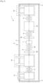
- Figure 1 illustrates a first embodiment of a motor-driven compressor 1 compressing, for example, a gas from a gas field or an associated gas from a petroleum field.
- the motor-driven compressor 1 comprises a housing 2 comprising a hollow elongated body 3 and a cover 4 at each of its ends so as to make the housing gas-tight, and two drive shafts 5 and 6 connected to each other by means of a flexible coupling device 7.
- the flexible coupling device 7 makes it possible to separate the bending modes of the shafts 5 and 6 and to dynamically balance each shaft, the vibratory behaviors of the shafts being independent.
- the first shaft 5 is supported in rotation in the housing 2 by two bearings 8 and 9, and the second shaft 6 is rotatably supported in the housing 2 by two bearings 10 and 11.
- the first, second, third and fourth bearings 8, 9, 10 and 11 are identical and comprise, for example, active magnetic bearings controlled by a control device (not shown).
- the motor-driven compressor 1 further comprises an electric motor 12 driving in rotation the first and second shafts 5 and 6 and whose rotor 12a is mounted on the first shaft 5 between the first and second bearings 8 and 9.
- a first compression section 13 is cantilevered at the free end of the first shaft 5 and a second compression section 14 is mounted between the third and fourth bearings 10 and 11 on the second shaft 6.
- Each compression section 13 and 14 comprises a gas inlet flange 13a and 14a, an outlet flange 13b and 14b of the gas compressed by the compression section 13 and 14, and a cartridge 13c and 14c connected to a first end of the inlet and outlet flanges.
- the inlet and outlet flanges are intended to be connected to gas treatment devices, for example a gas cooler, a compressed gas storage device, a supply device of gas at atmospheric pressure.
- gas treatment devices for example a gas cooler, a compressed gas storage device, a supply device of gas at atmospheric pressure.
- Each cartridge 13c and 14c comprises compression wheels 13d, 13e, 14d, 14e, 14f and 14g cooperating with diaphragms (not shown) so as to compress the gas received on the inlet flange 13a and 14a.
- a first axial thrust abutment 15 is mounted on the first shaft 5 between the first bearing 8 and the flexible coupling device 7, and a second axial thrust abutment 16 is mounted on the second shaft 6 between the third bearing 10 and the second compression section 14.
- the first and second axial thrust abutments 15 and 16 take up the forces exerted respectively by the electric motor and the compression sections on the shafts during the compression of a gas. They make it possible to control the axial displacement of the shafts 5 and 6 as a result of the thrust forces exerted by the motor or the compression sections.
- the number and location of the axial thrust abutments mounted on each shaft are determined so as to limit the axial displacement of each shaft comprising at least one compression section.
- the first compression section 13 may comprise one or more compression wheels, preferably two wheels 13d and 13e.
- the second compression section 14 may comprise one or more compression wheels, preferably no more than five wheels.
- the number of wheels of each compression section and the features of each of the wheels are determined in order to optimize the efficiency of the motor-driven compressor in the range of flow and pressure in which the motor-driven compressor 1 operates, and in order to minimize the stresses exerted on the bearings.
- the selection generally comprises a maximum of seven wheels.
- the first and second bearings 8 and 9 are sized according to the dynamic stresses generated mainly by the first compression section 13 and the rotor 12a of the electric motor 12, the stresses generated by the other elements mounted on the shaft being negligible, and the third and fourth bearings 10 and 11 are sized according to the dynamic stresses generated mainly by the second compression section 14, the other elements mounted on the shaft being negligible.
- the compression wheels of the first compression section 13 are easily accessible by disassembling the cover 4 and can be easily replaced when they are deteriorated or if the compression ratio of the motor-driven compressor 1 has to be modified, for example if the pressure of the received gas fluctuates according to the operating phase of the gas field.
- the first compression section 13 receives on its inlet flange 13a the gas entering the first time in the motor-driven compressor 1 generally wet promoting the corrosion and erosion of the compression wheels.
- the housing 2 may comprise several housings connected to each other, for example a motor housing comprising the motor 12 and the first compression section 13 and a compressor housing comprising the second compression section 14.
- the housing 2 may comprise a motor housing comprising the motor 12, a first compressor housing comprising the second compression section 14 and a second compressor housing comprising the first compression section 13.
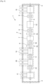
- This embodiment differs from the first embodiment in that a third compression section 17 is cantilevered to the free end of the second shaft 6.
- the third compression section 17 is identical in architecture to the first compression section 13 and preferably comprises two compression wheels.
- the wheels of the third compression section 17 are easily accessible by disassembling the cover 4.
- the additional compression section makes it possible to increase the wheel selection. Consequently, the pressure ratio generated by the motor-driven compressor 1 is higher than in the embodiment illustrated in Fig. 1 .
- the pressure and operating flow ranges of the motor-driven compressor 1 are extended compared with those of the first embodiment.
- the third and fourth bearings 10 and 11 are sized according to the dynamic stresses generated mainly by the second and third compression sections 14 and 17, the dynamic stresses due to the other elements mounted on the shaft being negligible.
- Fig. 3 illustrates a third embodiment of the motor-driven compressor 1 which differs from the second embodiment in that the second compression section 14 comprises two compression half-sections 18 and 19, each of architecture identical to that of the compression sections 13 and 17.
- the two half-sections 18 and 19 are mounted on the second shaft 6 so that, during the rotation of the shaft, the thrust generated by the first half-section 18 compensates for the thrust generated by the second half-section 19, reducing thus the thrust generated by the second compression section 14 and transmitted to the second axial thrust abutment 16.
- any compression section that is not cantilevered may comprise two compression half-sections.
- Fig. 4 illustrates a fourth embodiment of the motor-driven compressor 1 further comprising a fourth compression section of identical architecture to the first, second and third compression sections, and preferably comprising five compression wheels.
- This embodiment differs from the second embodiment in that a fourth compression section 20 is mounted on the second shaft 6 between the second and third compression sections 14 and 17.
- the fourth compression section 20 is separated from the second compression section 14 and 17 by the fourth bearing 11, and from the third compression section 17 by a fifth bearing 21.
- the number and features of the wheels of the compression sections are selected in order to limit the stresses exerted on the bearings and in order to reach the desired compression ratio.
- At least a fourth compression section makes it possible to adapt the motor-driven compressor to compression applications of a light gas with a high compression ratio, for example pure methane compressed at a pressure ratio greater than 10.
- compression sections or compression half-sections optimizes the cooling of the gas after each compression step.
- Figure 5 illustrates a fifth embodiment of the motor-driven compressor 1.
- This embodiment differs from the fourth embodiment in that one of the third and fourth compression sections 17 and 20, and the fifth bearing 21 are mounted on a third shaft 22 connected to the free end of the second shaft 6 by a second flexible coupling device 23.
- the third compression section 17 is cantilevered at the free end of the third shaft 22 and the fourth compression section 20 is mounted between the fifth bearing 21 and a sixth bearing 24 arranged between the second flexible coupling device 23 and the fourth compression section 20.
- the third shaft 22 further comprises a third axial thrust abutment 25 mounted between the third compression section 17 and the fifth bearing 21.
- the second flexible coupling device 23 makes it possible to separate the bending modes of the second and third shafts, thus increasing the value of the critical speed of the first bending mode of the drive shafts on which the second, third and fourth compression sections 14, 17 and 20 are mounted.
- the third and fourth bearings 10 and 11 are sized according to the dynamic stresses generated mainly by the second compression section 14, and the fifth and sixth bearings 21 and 24 are sized according to the dynamic stresses generated mainly by the third and fourth compression section 17 and 20, the dynamic stresses due to other elements mounted on the second and third shafts 6 and 22 being negligible.
- the cantilevered arrangement of at least one compression section and the use of a flexible coupling device make it possible to increase the value of the critical speed of the first bending mode of the drive shafts to a value greater than that of the nominal operating speed of the motor-driven compressor.
- the bearings supporting the shafts can be sized without taking into account the passage of the shafts through their first bending mode, thereby reducing the magnetic capacity of the bearings.
- the mounting of at least one cantilevered compression section facilitates the replacement of the wheels mounted in said section.
Landscapes
- Engineering & Computer Science (AREA)
- Mechanical Engineering (AREA)
- General Engineering & Computer Science (AREA)
- Physics & Mathematics (AREA)
- Electromagnetism (AREA)
- Structures Of Non-Positive Displacement Pumps (AREA)
- Applications Or Details Of Rotary Compressors (AREA)
- Connection Of Motors, Electrical Generators, Mechanical Devices, And The Like (AREA)
- Compressor (AREA)
Description
- The present invention relates to a motor driven compressor equipped with multiple compression sections and more particularly to the arrangement of the compression sections.
- A motor-driven compressor equipped with multiple compression sections includes a housing comprising an electric motor mounted on a drive shaft and intended for driving at least one compression section forming a compression line. A compression section includes one or more compression wheels for compressing a gas, mounted on the drive shaft.
- The drive shaft is held in the housing by bearings.
- When the rotational speeds are high, for example of the order of 30000 revolutions per minute, the compression sections and the motor are generally located between two active magnetic bearings so that the shaft is levitated.
- Since the nominal rotation speed of the compression shaft is generally greater than that of its first bending mode, when starting up and shutting down the electric motor, the drive shaft, on which the compression sections and the rotor of the electric motor, passes through the first bending mode, causing deformation of the shaft.
- It is necessary to size the active magnetic bearings so as to damp the dynamic response of the shaft.
- However, these large magnetic capacity bearings are sized for a transient state of the shaft. They are expensive and are driven by expensive electronic devices.
- High rotational speed motor-driven compressors comprising a compression shaft on which are mounted an electric motor and a compression section at each end of the shaft are known from the state of the art. An active magnetic bearing is arranged between a compression section and the electric motor.
- The compression sections are cantilevered to increase the value of the critical speed of the compression shaft so that it is greater than the value of the nominal speed of the electric motor.
- The active magnetic bearings and the electronic control devices are sized for the nominal operation of the motor-driven compressor in order to reduce the magnetic capacity of the bearings and consequently the cost of the bearings.
- However, the connection flanges of the gas inlet and outlet are arranged in an axial direction of the propeller shaft.
- Any intervention on the compression wheels or on the electric motor involves dismantling the pipes connected to the flanges.
- In addition, each section includes a single compression wheel limiting the wheel selection.
- The variation range of the compression ratio and the speed of the motor-driven compressor is low.
- For low pressure applications, for example when the motor-driven compressor compresses a gas from atmospheric pressure to a pressure of 10 bar and a low flow rate of the order of 2000 cubic meters per hour, the entire compression line may include five compression wheels.
-
WO 2017/013218 A1 discloses a subsea centrifugal compressor unit. - Reference can be made to
WO2017/153387 which illustrates a motor-driven compressor in which an expansion wheel is cantilevered. - The gas is expanded when passing in the single cantilevered wheel.
- Reference may also be made to
WO2015/032756 which illustrates a centrifugal compressor comprising a compression section mounted on a compression shaft between two bearings and a compression wheel mounted at a free end of the cantilevered shaft on the compressor side and comprising a trapped bearing. - An electric motor is intended to be connected to the shaft.
- As all the elements are mounted on the drive shaft, the bearings are solicited by all the elements mounted on the shaft, reducing the value of the critical speed of the first bending mode.
- In addition, the trapped bearing complicates the maintenance of the compressor.
- Therefore, it is proposed to overcome the disadvantages associated with the restricted selection of wheels by widening the operating range of the motor-driven compressor and to facilitate maintenance of the motor-driven compressor, while allowing operation at a nominal rotational speed of less than the critical speed of the first bending mode.
- In view of the above, it is proposed a motor-driven compressor with multiple compression sections, the motor-driven compressor comprising:
- at least one housing,
- at least two drive shafts, the at least twc drive shafts being supported in rotation in the housing by at least two bearings;
- a flexible coupling device connecting the drive shafts;
- an electric motor mounted on a first compression shaft of said at least two drive shafts; and
- at least two compression sections.
- A first compression section of said at least two compression sections is cantilevered at a free end of a first compression shaft of said at least two drive shafts and a second compression section is mounted between two bearings on a second compression shaft of said at least two drive shafts.
- Preferably, the first compression shaft has a first free end and is rotatably supported by a first pair of bearings.
- Advantageously, the second compression shaft has a second free end and is rotatably supported by a second pair of bearings.
- According to one feature, a flexible coupling device is connected to the first compression shaft and the second drive shaft.
- Preferably, a first compression section is cantilevered to the free end of the first drive shaft.
- Advantageously, a second compression section is mounted between the second pair of bearings of the second drive shaft.
- According to another feature, the motor-driven compressor further comprises:
- one or more additional compression sections mounted on the second compression shaft; and
- a bearing separating said additional compression section from an adjacent compression section.
- Preferably, the motor-driven compressor further comprises:
- a third compression shaft rotatably supported in the housing by at least two bearings; and
- a second flexible coupling device connecting the third shaft to the second free end of the second compression shaft; and
- at least one additional compression section mounted on the third shaft between the two bearings.
- Advantageously, the second flexible coupling device is connected to the second compression shaft and the third drive shaft.
- According to another feature, the third compression shaft comprises a third free end and is rotatably supported by a third pair of bearings.
- Preferably, each compression section comprises at least one compression wheel.
- Advantageously, the cantilevered compression section comprises two compression wheels.
- Preferably, each compression section comprises:
- an inlet flange; and
- an outlet flange,
- According to another feature, at least one compression section mounted between two bearings comprises two compression half-sections so that, during rotation of the drive shaft, the thrust generated by a half-section compensates for the thrust generated by the other half-section.
- Preferably, each compression half-section comprises:
- an inlet flange; and
- an output flange,
- Advantageously, the bearings comprise active magnetic bearings.
- Preferably, the motor-driven compressor further comprises an axial thrust abutment mounted on each compression shaft which comprises at least one compression section so as to control the axial displacement of the compression shaft as a result of thrust forces exerted by the compression section and/or the electric motor.
- Other features and advantages of the invention will appear on reading the following description of embodiments of the invention, given solely by way of nonlimiting examples and with reference to the drawings in which:
- [
Fig. 1 ] illustrates a first embodiment of a motor-driven compressor; - [
Fig. 2 ] illustrates a second embodiment of a motor-driven compressor; - [
Fig. 3 ] illustrates a third embodiment of a motor-driven compressor; - [
Fig. 4 ] illustrates a fourth embodiment of a motor-driven compressor; and - [
Fig. 5 ] illustrates a fifth embodiment of a motor-driven compressor. - Reference is made to
Figure 1 which illustrates a first embodiment of a motor-driven compressor 1 compressing, for example, a gas from a gas field or an associated gas from a petroleum field. - The motor-driven compressor 1 comprises a
housing 2 comprising a hollowelongated body 3 and acover 4 at each of its ends so as to make the housing gas-tight, and twodrive shafts flexible coupling device 7. - The
flexible coupling device 7 makes it possible to separate the bending modes of theshafts - The
first shaft 5 is supported in rotation in thehousing 2 by twobearings second shaft 6 is rotatably supported in thehousing 2 by twobearings - The first, second, third and
fourth bearings - The motor-driven compressor 1 further comprises an
electric motor 12 driving in rotation the first andsecond shafts rotor 12a is mounted on thefirst shaft 5 between the first andsecond bearings - A
first compression section 13 is cantilevered at the free end of thefirst shaft 5 and asecond compression section 14 is mounted between the third andfourth bearings second shaft 6. - Each
compression section gas inlet flange outlet flange compression section cartridge - The inlet and outlet flanges are intended to be connected to gas treatment devices, for example a gas cooler, a compressed gas storage device, a supply device of gas at atmospheric pressure.
- Each
cartridge compression wheels inlet flange - A first
axial thrust abutment 15 is mounted on thefirst shaft 5 between thefirst bearing 8 and theflexible coupling device 7, and a secondaxial thrust abutment 16 is mounted on thesecond shaft 6 between thethird bearing 10 and thesecond compression section 14. - The first and second
axial thrust abutments shafts - The number and location of the axial thrust abutments mounted on each shaft are determined so as to limit the axial displacement of each shaft comprising at least one compression section.
- The
first compression section 13 may comprise one or more compression wheels, preferably twowheels - The
second compression section 14 may comprise one or more compression wheels, preferably no more than five wheels. - The number of wheels of each compression section and the features of each of the wheels are determined in order to optimize the efficiency of the motor-driven compressor in the range of flow and pressure in which the motor-driven compressor 1 operates, and in order to minimize the stresses exerted on the bearings.
- Preferably, in this embodiment, the selection generally comprises a maximum of seven wheels.
- As the
flexible coupling device 7 makes it possible to separate the bending modes of the first and second shafts, the first andsecond bearings first compression section 13 and therotor 12a of theelectric motor 12, the stresses generated by the other elements mounted on the shaft being negligible, and the third andfourth bearings second compression section 14, the other elements mounted on the shaft being negligible. - As the
inlet flange 13a, and theoutlet flange 13b are arranged perpendicular to thecompression shaft 5, the compression wheels of thefirst compression section 13 are easily accessible by disassembling thecover 4 and can be easily replaced when they are deteriorated or if the compression ratio of the motor-driven compressor 1 has to be modified, for example if the pressure of the received gas fluctuates according to the operating phase of the gas field. - It is not necessary to disassemble the
body 3 and to disassemble the gas treatment devices connected to the inlet and outlet flanges of the motor-driven compressor 1. - Preferably, the
first compression section 13 receives on itsinlet flange 13a the gas entering the first time in the motor-driven compressor 1 generally wet promoting the corrosion and erosion of the compression wheels. - According to other embodiments, the
housing 2 may comprise several housings connected to each other, for example a motor housing comprising themotor 12 and thefirst compression section 13 and a compressor housing comprising thesecond compression section 14. - According to still other embodiments, the
housing 2 may comprise a motor housing comprising themotor 12, a first compressor housing comprising thesecond compression section 14 and a second compressor housing comprising thefirst compression section 13. - In what follows, the elements identical to those described above are identified by the same alphanumeric references
- Reference is made to
Figure 2 which illustrates a second embodiment of the motor-driven compressor 1. - This embodiment differs from the first embodiment in that a
third compression section 17 is cantilevered to the free end of thesecond shaft 6. - The
third compression section 17 is identical in architecture to thefirst compression section 13 and preferably comprises two compression wheels. - As in the case of the
first compression section 13, the wheels of thethird compression section 17 are easily accessible by disassembling thecover 4. - The additional compression section makes it possible to increase the wheel selection. Consequently, the pressure ratio generated by the motor-driven compressor 1 is higher than in the embodiment illustrated in
Fig. 1 . - The pressure and operating flow ranges of the motor-driven compressor 1 are extended compared with those of the first embodiment.
- In this embodiment, the third and
fourth bearings third compression sections -
Fig. 3 illustrates a third embodiment of the motor-driven compressor 1 which differs from the second embodiment in that thesecond compression section 14 comprises two compression half-sections compression sections - The two half-
sections second shaft 6 so that, during the rotation of the shaft, the thrust generated by the first half-section 18 compensates for the thrust generated by the second half-section 19, reducing thus the thrust generated by thesecond compression section 14 and transmitted to the secondaxial thrust abutment 16. - Such an arrangement is known as "back to back".
- Of course, any compression section that is not cantilevered may comprise two compression half-sections.
-
Fig. 4 illustrates a fourth embodiment of the motor-driven compressor 1 further comprising a fourth compression section of identical architecture to the first, second and third compression sections, and preferably comprising five compression wheels. - This embodiment differs from the second embodiment in that a
fourth compression section 20 is mounted on thesecond shaft 6 between the second andthird compression sections - The
fourth compression section 20 is separated from thesecond compression section fourth bearing 11, and from thethird compression section 17 by afifth bearing 21. - The number and features of the wheels of the compression sections are selected in order to limit the stresses exerted on the bearings and in order to reach the desired compression ratio.
- The addition of at least a fourth compression section makes it possible to adapt the motor-driven compressor to compression applications of a light gas with a high compression ratio, for example pure methane compressed at a pressure ratio greater than 10.
- Furthermore, the addition of compression sections or compression half-sections optimizes the cooling of the gas after each compression step.
- Indeed, it is easy to add a gas cooler between the outlet flange of a compression section and the inlet flange of the adjacent compression section.
- Reference is made to
Figure 5 which illustrates a fifth embodiment of the motor-driven compressor 1. This embodiment differs from the fourth embodiment in that one of the third andfourth compression sections fifth bearing 21 are mounted on athird shaft 22 connected to the free end of thesecond shaft 6 by a secondflexible coupling device 23. - The
third compression section 17 is cantilevered at the free end of thethird shaft 22 and thefourth compression section 20 is mounted between thefifth bearing 21 and asixth bearing 24 arranged between the secondflexible coupling device 23 and thefourth compression section 20. - The
third shaft 22 further comprises a thirdaxial thrust abutment 25 mounted between thethird compression section 17 and thefifth bearing 21. - Compared to the fourth embodiment, for the same number of compression sections, the second
flexible coupling device 23 makes it possible to separate the bending modes of the second and third shafts, thus increasing the value of the critical speed of the first bending mode of the drive shafts on which the second, third andfourth compression sections - In this embodiment, the third and
fourth bearings second compression section 14, and the fifth andsixth bearings fourth compression section third shafts - Advantageously, the cantilevered arrangement of at least one compression section and the use of a flexible coupling device make it possible to increase the value of the critical speed of the first bending mode of the drive shafts to a value greater than that of the nominal operating speed of the motor-driven compressor.
- Consequently, the bearings supporting the shafts can be sized without taking into account the passage of the shafts through their first bending mode, thereby reducing the magnetic capacity of the bearings.
- In addition, the mounting of at least one cantilevered compression section facilitates the replacement of the wheels mounted in said section.
Claims (12)
- A motor-driven compressor with multiple compression sections, the motor-driven compressor comprising:- at least one housing (2);- at least two drive shafts (5, 6), the at least two drive shafts being rotatably supported in the housing by at least two bearings (8, 9, 10, 11, 21, 24);- a flexible coupling device (7) connecting the drive shafts;- an electric motor (12) mounted on a first compression shaft (5) of said at least two drive shafts; and- at least two compression sections (13, 14, 17, 20), wherein:
a first compression section (13, 17) of said at least two compression sections is cantilevered at a free end of the first compression shaft (5) of said at least two drive shafts, and a second compression section (14, 20) is mounted between two bearings (10, 11, 21) on the second compression shaft (6) of said at least two drive shafts. - The motor-driven compressor according to claim 1, further comprising:- one or more additional compression sections (20) mounted on the second compression shaft (6); and- a bearing (11, 21) separating said additional compression section (20) from an adjacent compression section.
- The motor-driven compressor according to claim 1 or claim 2, further comprising:- a third compression shaft (22) rotatably supported in the housing by at least two bearings (21, 24);- a second flexible coupling device (25) connecting the third shaft to the second free end of the second compression shaft (6); and- at least one additional compression section (20) mounted on the third shaft between the two bearings (21, 24).
- The motor-driven compressor according to claim 3, wherein the second flexible coupling device (25) is connected to the second compression shaft (6) and the third compression shaft (22).
- The motor-driven compressor according to claim 3 or 4, wherein the third compression shaft (22) comprises a third free end and is rotatably supported by a third pair of bearings (21, 24).
- The motor-driven compressor according to any one of claims 1 to 5, wherein each compression section comprises at least one compression wheel (13d, 13e, 14d, 14e, 14f, 14g).
- The motor-driven compressor according to any one of claims 1 to 6, wherein the cantilevered compression section (13, 17) comprises two compression wheels (13d, 13e).
- The motor-driven compressor according to any one of claims 1 to 7, wherein each compression section (13, 14, 17, 20) comprises:- an inlet flange (13a, 14a); and- an outlet flange (13b, 14b),
said flanges being arranged perpendicular to the drive shafts (5, 6). - The motor-driven compressor according to any one of claims 1 to 8, wherein at least one compression section (14), mounted between two bearings (11, 16), comprises two compression half-sections (18, 19) so that, during the rotation of the drive shaft, the thrust generated by a half-section compensates for the thrust generated by the other half-section.
- The motor-driven compressor according to claim 9, wherein each compression half-section (18, 19) comprises:- an inlet flange; and- an outlet flange,
said flanges being arranged perpendicular to the drive shafts (5, 6). - The motor-driven compressor according to any one of claims 1 to 10, wherein the bearings (8, 9, 10, 11, 21, 24) comprise active magnetic bearings.
- The motor-driven compressor according to any one of the preceding claims, further comprising an axial thrust abutment (15, 16, 25), mounted on each compression shaft (5, 6, 22), which comprises at least one compression section ( 13, 14, 17, 20) so as to control the axial displacement of the compression shaft as a result of thrust forces exerted by the compression section and/or the electric motor (12).
Applications Claiming Priority (2)
| Application Number | Priority Date | Filing Date | Title |
|---|---|---|---|
| FR1871647A FR3088686B1 (en) | 2018-11-21 | 2018-11-21 | MOTORCOMPRESSOR WITH MULTIPLE COMPRESSION SECTIONS |
| PCT/EP2019/025407 WO2020104062A1 (en) | 2018-11-21 | 2019-11-20 | Compressor with multiple shafts and with a cantilevered compression stage |
Publications (2)
| Publication Number | Publication Date |
|---|---|
| EP3884167A1 EP3884167A1 (en) | 2021-09-29 |
| EP3884167B1 true EP3884167B1 (en) | 2024-01-10 |
Family
ID=66286420
Family Applications (1)
| Application Number | Title | Priority Date | Filing Date |
|---|---|---|---|
| EP19817142.3A Active EP3884167B1 (en) | 2018-11-21 | 2019-11-20 | Compressor with multiple shafts and with a cantilevered compression stage |
Country Status (6)
| Country | Link |
|---|---|
| US (1) | US11898566B2 (en) |
| EP (1) | EP3884167B1 (en) |
| JP (1) | JP7257513B2 (en) |
| CN (1) | CN113272558B (en) |
| FR (1) | FR3088686B1 (en) |
| WO (1) | WO2020104062A1 (en) |
Families Citing this family (2)
| Publication number | Priority date | Publication date | Assignee | Title |
|---|---|---|---|---|
| FI130850B1 (en) * | 2021-06-10 | 2024-04-24 | Lappeenrannan Lahden Teknillinen Yliopisto Lut | An electric machine system |
| GB202115352D0 (en) | 2021-10-26 | 2021-12-08 | Rolls Royce Plc | Cabin blower system |
Citations (1)
| Publication number | Priority date | Publication date | Assignee | Title |
|---|---|---|---|---|
| EP0301285B1 (en) * | 1987-07-23 | 1991-10-02 | Mitsubishi Jukogyo Kabushiki Kaisha | Centrifugal compressor |
Family Cites Families (19)
| Publication number | Priority date | Publication date | Assignee | Title |
|---|---|---|---|---|
| FR644751A (en) * | 1926-12-13 | 1928-10-13 | Rateau Soc | Device for raising the critical speed of a rotary compressor mobile |
| JPS58168861U (en) * | 1982-05-08 | 1983-11-10 | 三菱電機株式会社 | Totally enclosed external sector electric motor |
| JPH0322559Y2 (en) * | 1985-06-20 | 1991-05-16 | ||
| DE3729486C1 (en) * | 1987-09-03 | 1988-12-15 | Gutehoffnungshuette Man | Compressor unit |
| JPH06335202A (en) * | 1993-05-25 | 1994-12-02 | Fuji Electric Co Ltd | Totally-enclosed fan-cooled rotating electric machine |
| US6176092B1 (en) * | 1998-10-09 | 2001-01-23 | American Standard Inc. | Oil-free liquid chiller |
| ES2586658T3 (en) * | 2003-03-10 | 2016-10-18 | Thermodyn | Centrifugal Compressor Group |
| US9726196B2 (en) * | 2010-10-27 | 2017-08-08 | Dresser-Rand Company | System and cooling for rapid pressurization of a motor-bearing cooling loop for a hermetically sealed motor/compressor system |
| US9200643B2 (en) * | 2010-10-27 | 2015-12-01 | Dresser-Rand Company | Method and system for cooling a motor-compressor with a closed-loop cooling circuit |
| EP2633197A4 (en) * | 2010-10-27 | 2016-08-03 | Dresser Rand Co | Multiple motor drivers for a hermetically-sealed motor-compressor system |
| US9206819B2 (en) * | 2011-06-01 | 2015-12-08 | Dresser-Rand Company | Subsea motor-compressor cooling system |
| ITCO20120024A1 (en) * | 2012-05-09 | 2013-11-10 | Nuovo Pignone Srl | PRESSURE EQUALIZER |
| ITFI20130204A1 (en) * | 2013-09-03 | 2015-03-04 | Nuovo Pignone Srl | "FAN-COOLED ELECTRICAL MACHINE WITH AXIAL THRUST COMPENSATION" |
| ITFI20130208A1 (en) | 2013-09-05 | 2015-03-06 | Nuovo Pignone Srl | "MULTISTAGE CENTRIFUGAL COMPRESSOR" |
| US11421696B2 (en) * | 2014-12-31 | 2022-08-23 | Ingersoll-Rand Industrial U.S., Inc. | Multi-stage compressor with single electric direct drive motor |
| WO2017007523A1 (en) * | 2015-07-08 | 2017-01-12 | Exxonmobil Upstream Research Company | Modular configurable compression systems and methods |
| EP3121449B1 (en) * | 2015-07-22 | 2022-10-05 | Thermodyn | Subsea centrifugal compressor with horizontal shaft and with only one axial thrust bearing |
| ITUA20161513A1 (en) | 2016-03-09 | 2017-09-09 | Nuovo Pignone Tecnologie Srl | MOTORCOMPRESSOR - INTEGRATED ESPANTOR |
| JP2017192176A (en) * | 2016-04-11 | 2017-10-19 | 株式会社日立産機システム | Rotary electric machine |
-
2018
- 2018-11-21 FR FR1871647A patent/FR3088686B1/en active Active
-
2019
- 2019-11-20 JP JP2021527160A patent/JP7257513B2/en active Active
- 2019-11-20 WO PCT/EP2019/025407 patent/WO2020104062A1/en not_active Ceased
- 2019-11-20 CN CN201980075860.2A patent/CN113272558B/en active Active
- 2019-11-20 EP EP19817142.3A patent/EP3884167B1/en active Active
-
2021
- 2021-05-14 US US17/320,914 patent/US11898566B2/en active Active
Patent Citations (1)
| Publication number | Priority date | Publication date | Assignee | Title |
|---|---|---|---|---|
| EP0301285B1 (en) * | 1987-07-23 | 1991-10-02 | Mitsubishi Jukogyo Kabushiki Kaisha | Centrifugal compressor |
Also Published As
| Publication number | Publication date |
|---|---|
| EP3884167A1 (en) | 2021-09-29 |
| BR112021009635A2 (en) | 2021-08-10 |
| WO2020104062A1 (en) | 2020-05-28 |
| JP7257513B2 (en) | 2023-04-13 |
| US11898566B2 (en) | 2024-02-13 |
| CN113272558B (en) | 2024-04-30 |
| FR3088686B1 (en) | 2021-10-01 |
| FR3088686A1 (en) | 2020-05-22 |
| JP2022507717A (en) | 2022-01-18 |
| CN113272558A (en) | 2021-08-17 |
| US20220074418A1 (en) | 2022-03-10 |
Similar Documents
| Publication | Publication Date | Title |
|---|---|---|
| EP2524144B1 (en) | Integral compressor-expander | |
| US7144226B2 (en) | Centrifugal compressor having a flexible coupling | |
| EP2384399B1 (en) | Improvements in multi-stage centrifugal compressors | |
| US20070065300A1 (en) | Multi-stage compression system including variable speed motors | |
| JP5863320B2 (en) | Centrifugal compressor | |
| JP5802216B2 (en) | Mid span gas bearing | |
| EP2386763B1 (en) | Multistage compressor with balancing pistons | |
| US11421696B2 (en) | Multi-stage compressor with single electric direct drive motor | |
| JPS5817358B2 (en) | Multi-stage turbo compressor | |
| US11898566B2 (en) | Motor-driven compressor having a compression section mounted on a free end of a cantilvered shaft | |
| JP2007177695A (en) | Turbo compressor | |
| AU2016295175B2 (en) | Subsea centrifugal compressor with horizontal shaft and with only one axial thrust bearing | |
| EP2604862A1 (en) | A compressor arrangement | |
| WO2013182492A1 (en) | High pressure ratio compressors with multiple intercooling and related methods | |
| EP3935270B1 (en) | Multistage compressor-expander turbomachine configuration | |
| EP3859161B1 (en) | Rotary machine | |
| CN102859202B (en) | Axial flow compressor | |
| RU2779733C1 (en) | Compressor with multiple shafts and a cantilevered compression stage | |
| EP0883749A1 (en) | Compressors | |
| US20110171015A1 (en) | Centrifugal compressor and fabricating method thereof | |
| CN113629965A (en) | MCL compressor system with compressor directly connected with magnetic suspension motor | |
| BR112021009635B1 (en) | ENGINE-DRIVEN COMPRESSOR WITH MULTIPLE COMPRESSION SECTIONS | |
| JPH0754637Y2 (en) | Multi-stage turbo compressor | |
| KR20190122608A (en) | Turbo Compressor | |
| EP2538020A2 (en) | Gas Turbines |
Legal Events
| Date | Code | Title | Description |
|---|---|---|---|
| STAA | Information on the status of an ep patent application or granted ep patent |
Free format text: STATUS: UNKNOWN |
|
| STAA | Information on the status of an ep patent application or granted ep patent |
Free format text: STATUS: THE INTERNATIONAL PUBLICATION HAS BEEN MADE |
|
| PUAI | Public reference made under article 153(3) epc to a published international application that has entered the european phase |
Free format text: ORIGINAL CODE: 0009012 |
|
| STAA | Information on the status of an ep patent application or granted ep patent |
Free format text: STATUS: REQUEST FOR EXAMINATION WAS MADE |
|
| 17P | Request for examination filed |
Effective date: 20210604 |
|
| AK | Designated contracting states |
Kind code of ref document: A1 Designated state(s): AL AT BE BG CH CY CZ DE DK EE ES FI FR GB GR HR HU IE IS IT LI LT LU LV MC MK MT NL NO PL PT RO RS SE SI SK SM TR |
|
| DAV | Request for validation of the european patent (deleted) | ||
| DAX | Request for extension of the european patent (deleted) | ||
| P01 | Opt-out of the competence of the unified patent court (upc) registered |
Effective date: 20230526 |
|
| GRAP | Despatch of communication of intention to grant a patent |
Free format text: ORIGINAL CODE: EPIDOSNIGR1 |
|
| STAA | Information on the status of an ep patent application or granted ep patent |
Free format text: STATUS: GRANT OF PATENT IS INTENDED |
|
| INTG | Intention to grant announced |
Effective date: 20231023 |
|
| GRAS | Grant fee paid |
Free format text: ORIGINAL CODE: EPIDOSNIGR3 |
|
| GRAA | (expected) grant |
Free format text: ORIGINAL CODE: 0009210 |
|
| STAA | Information on the status of an ep patent application or granted ep patent |
Free format text: STATUS: THE PATENT HAS BEEN GRANTED |
|
| AK | Designated contracting states |
Kind code of ref document: B1 Designated state(s): AL AT BE BG CH CY CZ DE DK EE ES FI FR GB GR HR HU IE IS IT LI LT LU LV MC MK MT NL NO PL PT RO RS SE SI SK SM TR |
|
| REG | Reference to a national code |
Ref country code: GB Ref legal event code: FG4D |
|
| REG | Reference to a national code |
Ref country code: CH Ref legal event code: EP |
|
| REG | Reference to a national code |
Ref country code: DE Ref legal event code: R096 Ref document number: 602019044982 Country of ref document: DE |
|
| REG | Reference to a national code |
Ref country code: IE Ref legal event code: FG4D |
|
| REG | Reference to a national code |
Ref country code: LT Ref legal event code: MG9D |
|
| REG | Reference to a national code |
Ref country code: NL Ref legal event code: MP Effective date: 20240110 |
|
| REG | Reference to a national code |
Ref country code: AT Ref legal event code: MK05 Ref document number: 1649090 Country of ref document: AT Kind code of ref document: T Effective date: 20240110 |
|
| PG25 | Lapsed in a contracting state [announced via postgrant information from national office to epo] |
Ref country code: NL Free format text: LAPSE BECAUSE OF FAILURE TO SUBMIT A TRANSLATION OF THE DESCRIPTION OR TO PAY THE FEE WITHIN THE PRESCRIBED TIME-LIMIT Effective date: 20240110 |
|
| PG25 | Lapsed in a contracting state [announced via postgrant information from national office to epo] |
Ref country code: NL Free format text: LAPSE BECAUSE OF FAILURE TO SUBMIT A TRANSLATION OF THE DESCRIPTION OR TO PAY THE FEE WITHIN THE PRESCRIBED TIME-LIMIT Effective date: 20240110 |
|
| PG25 | Lapsed in a contracting state [announced via postgrant information from national office to epo] |
Ref country code: IS Free format text: LAPSE BECAUSE OF FAILURE TO SUBMIT A TRANSLATION OF THE DESCRIPTION OR TO PAY THE FEE WITHIN THE PRESCRIBED TIME-LIMIT Effective date: 20240510 |
|
| PG25 | Lapsed in a contracting state [announced via postgrant information from national office to epo] |
Ref country code: LT Free format text: LAPSE BECAUSE OF FAILURE TO SUBMIT A TRANSLATION OF THE DESCRIPTION OR TO PAY THE FEE WITHIN THE PRESCRIBED TIME-LIMIT Effective date: 20240110 |
|
| PG25 | Lapsed in a contracting state [announced via postgrant information from national office to epo] |
Ref country code: GR Free format text: LAPSE BECAUSE OF FAILURE TO SUBMIT A TRANSLATION OF THE DESCRIPTION OR TO PAY THE FEE WITHIN THE PRESCRIBED TIME-LIMIT Effective date: 20240411 |
|
| PG25 | Lapsed in a contracting state [announced via postgrant information from national office to epo] |
Ref country code: RS Free format text: LAPSE BECAUSE OF FAILURE TO SUBMIT A TRANSLATION OF THE DESCRIPTION OR TO PAY THE FEE WITHIN THE PRESCRIBED TIME-LIMIT Effective date: 20240410 Ref country code: HR Free format text: LAPSE BECAUSE OF FAILURE TO SUBMIT A TRANSLATION OF THE DESCRIPTION OR TO PAY THE FEE WITHIN THE PRESCRIBED TIME-LIMIT Effective date: 20240110 |
|
| PG25 | Lapsed in a contracting state [announced via postgrant information from national office to epo] |
Ref country code: ES Free format text: LAPSE BECAUSE OF FAILURE TO SUBMIT A TRANSLATION OF THE DESCRIPTION OR TO PAY THE FEE WITHIN THE PRESCRIBED TIME-LIMIT Effective date: 20240110 |
|
| PG25 | Lapsed in a contracting state [announced via postgrant information from national office to epo] |
Ref country code: AT Free format text: LAPSE BECAUSE OF FAILURE TO SUBMIT A TRANSLATION OF THE DESCRIPTION OR TO PAY THE FEE WITHIN THE PRESCRIBED TIME-LIMIT Effective date: 20240110 |
|
| PG25 | Lapsed in a contracting state [announced via postgrant information from national office to epo] |
Ref country code: RS Free format text: LAPSE BECAUSE OF FAILURE TO SUBMIT A TRANSLATION OF THE DESCRIPTION OR TO PAY THE FEE WITHIN THE PRESCRIBED TIME-LIMIT Effective date: 20240410 Ref country code: LT Free format text: LAPSE BECAUSE OF FAILURE TO SUBMIT A TRANSLATION OF THE DESCRIPTION OR TO PAY THE FEE WITHIN THE PRESCRIBED TIME-LIMIT Effective date: 20240110 Ref country code: IS Free format text: LAPSE BECAUSE OF FAILURE TO SUBMIT A TRANSLATION OF THE DESCRIPTION OR TO PAY THE FEE WITHIN THE PRESCRIBED TIME-LIMIT Effective date: 20240510 Ref country code: HR Free format text: LAPSE BECAUSE OF FAILURE TO SUBMIT A TRANSLATION OF THE DESCRIPTION OR TO PAY THE FEE WITHIN THE PRESCRIBED TIME-LIMIT Effective date: 20240110 Ref country code: GR Free format text: LAPSE BECAUSE OF FAILURE TO SUBMIT A TRANSLATION OF THE DESCRIPTION OR TO PAY THE FEE WITHIN THE PRESCRIBED TIME-LIMIT Effective date: 20240411 Ref country code: ES Free format text: LAPSE BECAUSE OF FAILURE TO SUBMIT A TRANSLATION OF THE DESCRIPTION OR TO PAY THE FEE WITHIN THE PRESCRIBED TIME-LIMIT Effective date: 20240110 Ref country code: BG Free format text: LAPSE BECAUSE OF FAILURE TO SUBMIT A TRANSLATION OF THE DESCRIPTION OR TO PAY THE FEE WITHIN THE PRESCRIBED TIME-LIMIT Effective date: 20240110 Ref country code: AT Free format text: LAPSE BECAUSE OF FAILURE TO SUBMIT A TRANSLATION OF THE DESCRIPTION OR TO PAY THE FEE WITHIN THE PRESCRIBED TIME-LIMIT Effective date: 20240110 |
|
| PG25 | Lapsed in a contracting state [announced via postgrant information from national office to epo] |
Ref country code: PT Free format text: LAPSE BECAUSE OF FAILURE TO SUBMIT A TRANSLATION OF THE DESCRIPTION OR TO PAY THE FEE WITHIN THE PRESCRIBED TIME-LIMIT Effective date: 20240510 Ref country code: PL Free format text: LAPSE BECAUSE OF FAILURE TO SUBMIT A TRANSLATION OF THE DESCRIPTION OR TO PAY THE FEE WITHIN THE PRESCRIBED TIME-LIMIT Effective date: 20240110 |
|
| PG25 | Lapsed in a contracting state [announced via postgrant information from national office to epo] |
Ref country code: SE Free format text: LAPSE BECAUSE OF FAILURE TO SUBMIT A TRANSLATION OF THE DESCRIPTION OR TO PAY THE FEE WITHIN THE PRESCRIBED TIME-LIMIT Effective date: 20240110 Ref country code: PT Free format text: LAPSE BECAUSE OF FAILURE TO SUBMIT A TRANSLATION OF THE DESCRIPTION OR TO PAY THE FEE WITHIN THE PRESCRIBED TIME-LIMIT Effective date: 20240510 Ref country code: PL Free format text: LAPSE BECAUSE OF FAILURE TO SUBMIT A TRANSLATION OF THE DESCRIPTION OR TO PAY THE FEE WITHIN THE PRESCRIBED TIME-LIMIT Effective date: 20240110 Ref country code: LV Free format text: LAPSE BECAUSE OF FAILURE TO SUBMIT A TRANSLATION OF THE DESCRIPTION OR TO PAY THE FEE WITHIN THE PRESCRIBED TIME-LIMIT Effective date: 20240110 |
|
| PG25 | Lapsed in a contracting state [announced via postgrant information from national office to epo] |
Ref country code: DK Free format text: LAPSE BECAUSE OF FAILURE TO SUBMIT A TRANSLATION OF THE DESCRIPTION OR TO PAY THE FEE WITHIN THE PRESCRIBED TIME-LIMIT Effective date: 20240110 |
|
| REG | Reference to a national code |
Ref country code: DE Ref legal event code: R097 Ref document number: 602019044982 Country of ref document: DE |
|
| PG25 | Lapsed in a contracting state [announced via postgrant information from national office to epo] |
Ref country code: SM Free format text: LAPSE BECAUSE OF FAILURE TO SUBMIT A TRANSLATION OF THE DESCRIPTION OR TO PAY THE FEE WITHIN THE PRESCRIBED TIME-LIMIT Effective date: 20240110 |
|
| PG25 | Lapsed in a contracting state [announced via postgrant information from national office to epo] |
Ref country code: CZ Free format text: LAPSE BECAUSE OF FAILURE TO SUBMIT A TRANSLATION OF THE DESCRIPTION OR TO PAY THE FEE WITHIN THE PRESCRIBED TIME-LIMIT Effective date: 20240110 Ref country code: EE Free format text: LAPSE BECAUSE OF FAILURE TO SUBMIT A TRANSLATION OF THE DESCRIPTION OR TO PAY THE FEE WITHIN THE PRESCRIBED TIME-LIMIT Effective date: 20240110 |
|
| PG25 | Lapsed in a contracting state [announced via postgrant information from national office to epo] |
Ref country code: SK Free format text: LAPSE BECAUSE OF FAILURE TO SUBMIT A TRANSLATION OF THE DESCRIPTION OR TO PAY THE FEE WITHIN THE PRESCRIBED TIME-LIMIT Effective date: 20240110 |
|
| PG25 | Lapsed in a contracting state [announced via postgrant information from national office to epo] |
Ref country code: SM Free format text: LAPSE BECAUSE OF FAILURE TO SUBMIT A TRANSLATION OF THE DESCRIPTION OR TO PAY THE FEE WITHIN THE PRESCRIBED TIME-LIMIT Effective date: 20240110 Ref country code: SK Free format text: LAPSE BECAUSE OF FAILURE TO SUBMIT A TRANSLATION OF THE DESCRIPTION OR TO PAY THE FEE WITHIN THE PRESCRIBED TIME-LIMIT Effective date: 20240110 Ref country code: RO Free format text: LAPSE BECAUSE OF FAILURE TO SUBMIT A TRANSLATION OF THE DESCRIPTION OR TO PAY THE FEE WITHIN THE PRESCRIBED TIME-LIMIT Effective date: 20240110 Ref country code: EE Free format text: LAPSE BECAUSE OF FAILURE TO SUBMIT A TRANSLATION OF THE DESCRIPTION OR TO PAY THE FEE WITHIN THE PRESCRIBED TIME-LIMIT Effective date: 20240110 Ref country code: DK Free format text: LAPSE BECAUSE OF FAILURE TO SUBMIT A TRANSLATION OF THE DESCRIPTION OR TO PAY THE FEE WITHIN THE PRESCRIBED TIME-LIMIT Effective date: 20240110 Ref country code: CZ Free format text: LAPSE BECAUSE OF FAILURE TO SUBMIT A TRANSLATION OF THE DESCRIPTION OR TO PAY THE FEE WITHIN THE PRESCRIBED TIME-LIMIT Effective date: 20240110 |
|
| PLBE | No opposition filed within time limit |
Free format text: ORIGINAL CODE: 0009261 |
|
| STAA | Information on the status of an ep patent application or granted ep patent |
Free format text: STATUS: NO OPPOSITION FILED WITHIN TIME LIMIT |
|
| 26N | No opposition filed |
Effective date: 20241011 |
|
| PG25 | Lapsed in a contracting state [announced via postgrant information from national office to epo] |
Ref country code: SI Free format text: LAPSE BECAUSE OF FAILURE TO SUBMIT A TRANSLATION OF THE DESCRIPTION OR TO PAY THE FEE WITHIN THE PRESCRIBED TIME-LIMIT Effective date: 20240110 |
|
| PG25 | Lapsed in a contracting state [announced via postgrant information from national office to epo] |
Ref country code: MC Free format text: LAPSE BECAUSE OF FAILURE TO SUBMIT A TRANSLATION OF THE DESCRIPTION OR TO PAY THE FEE WITHIN THE PRESCRIBED TIME-LIMIT Effective date: 20240110 |
|
| PG25 | Lapsed in a contracting state [announced via postgrant information from national office to epo] |
Ref country code: LU Free format text: LAPSE BECAUSE OF NON-PAYMENT OF DUE FEES Effective date: 20241120 |
|
| REG | Reference to a national code |
Ref country code: BE Ref legal event code: MM Effective date: 20241130 |
|
| PG25 | Lapsed in a contracting state [announced via postgrant information from national office to epo] |
Ref country code: FI Free format text: LAPSE BECAUSE OF FAILURE TO SUBMIT A TRANSLATION OF THE DESCRIPTION OR TO PAY THE FEE WITHIN THE PRESCRIBED TIME-LIMIT Effective date: 20240110 |
|
| PG25 | Lapsed in a contracting state [announced via postgrant information from national office to epo] |
Ref country code: BE Free format text: LAPSE BECAUSE OF NON-PAYMENT OF DUE FEES Effective date: 20241130 |
|
| PG25 | Lapsed in a contracting state [announced via postgrant information from national office to epo] |
Ref country code: FR Free format text: LAPSE BECAUSE OF NON-PAYMENT OF DUE FEES Effective date: 20241130 |
|
| PG25 | Lapsed in a contracting state [announced via postgrant information from national office to epo] |
Ref country code: IE Free format text: LAPSE BECAUSE OF NON-PAYMENT OF DUE FEES Effective date: 20241120 |
|
| REG | Reference to a national code |
Ref country code: CH Ref legal event code: U11 Free format text: ST27 STATUS EVENT CODE: U-0-0-U10-U11 (AS PROVIDED BY THE NATIONAL OFFICE) Effective date: 20251201 |
|
| PGFP | Annual fee paid to national office [announced via postgrant information from national office to epo] |
Ref country code: DE Payment date: 20251022 Year of fee payment: 7 |
|
| PGFP | Annual fee paid to national office [announced via postgrant information from national office to epo] |
Ref country code: GB Payment date: 20251022 Year of fee payment: 7 |
|
| PGFP | Annual fee paid to national office [announced via postgrant information from national office to epo] |
Ref country code: NO Payment date: 20251024 Year of fee payment: 7 |
|
| PGFP | Annual fee paid to national office [announced via postgrant information from national office to epo] |
Ref country code: IT Payment date: 20251022 Year of fee payment: 7 |
|
| PGFP | Annual fee paid to national office [announced via postgrant information from national office to epo] |
Ref country code: CH Payment date: 20251201 Year of fee payment: 7 |
|
| PG25 | Lapsed in a contracting state [announced via postgrant information from national office to epo] |
Ref country code: HU Free format text: LAPSE BECAUSE OF FAILURE TO SUBMIT A TRANSLATION OF THE DESCRIPTION OR TO PAY THE FEE WITHIN THE PRESCRIBED TIME-LIMIT; INVALID AB INITIO Effective date: 20191120 |
|
| PG25 | Lapsed in a contracting state [announced via postgrant information from national office to epo] |
Ref country code: CY Free format text: LAPSE BECAUSE OF FAILURE TO SUBMIT A TRANSLATION OF THE DESCRIPTION OR TO PAY THE FEE WITHIN THE PRESCRIBED TIME-LIMIT; INVALID AB INITIO Effective date: 20191120 |