EP3883848B1 - A system for transferring an object from a ship to an offshore structure - Google Patents
A system for transferring an object from a ship to an offshore structure Download PDFInfo
- Publication number
- EP3883848B1 EP3883848B1 EP19790010.3A EP19790010A EP3883848B1 EP 3883848 B1 EP3883848 B1 EP 3883848B1 EP 19790010 A EP19790010 A EP 19790010A EP 3883848 B1 EP3883848 B1 EP 3883848B1
- Authority
- EP
- European Patent Office
- Prior art keywords
- ship
- offshore structure
- hoisting
- motion
- power supply
- Prior art date
- Legal status (The legal status is an assumption and is not a legal conclusion. Google has not performed a legal analysis and makes no representation as to the accuracy of the status listed.)
- Active
Links
Images
Classifications
-
- B—PERFORMING OPERATIONS; TRANSPORTING
- B63—SHIPS OR OTHER WATERBORNE VESSELS; RELATED EQUIPMENT
- B63B—SHIPS OR OTHER WATERBORNE VESSELS; EQUIPMENT FOR SHIPPING
- B63B27/00—Arrangement of ship-based loading or unloading equipment for cargo or passengers
- B63B27/16—Arrangement of ship-based loading or unloading equipment for cargo or passengers of lifts or hoists
-
- B—PERFORMING OPERATIONS; TRANSPORTING
- B63—SHIPS OR OTHER WATERBORNE VESSELS; RELATED EQUIPMENT
- B63B—SHIPS OR OTHER WATERBORNE VESSELS; EQUIPMENT FOR SHIPPING
- B63B27/00—Arrangement of ship-based loading or unloading equipment for cargo or passengers
- B63B27/18—Arrangement of ship-based loading or unloading equipment for cargo or passengers of cableways, e.g. with breeches-buoys
-
- B—PERFORMING OPERATIONS; TRANSPORTING
- B66—HOISTING; LIFTING; HAULING
- B66C—CRANES; LOAD-ENGAGING ELEMENTS OR DEVICES FOR CRANES, CAPSTANS, WINCHES, OR TACKLES
- B66C13/00—Other constructional features or details
- B66C13/02—Devices for facilitating retrieval of floating objects, e.g. for recovering crafts from water
-
- B—PERFORMING OPERATIONS; TRANSPORTING
- B66—HOISTING; LIFTING; HAULING
- B66D—CAPSTANS; WINCHES; TACKLES, e.g. PULLEY BLOCKS; HOISTS
- B66D1/00—Rope, cable, or chain winding mechanisms; Capstans
- B66D1/28—Other constructional details
- B66D1/40—Control devices
- B66D1/48—Control devices automatic
- B66D1/52—Control devices automatic for varying rope or cable tension, e.g. when recovering craft from water
- B66D1/525—Control devices automatic for varying rope or cable tension, e.g. when recovering craft from water electrical
-
- B—PERFORMING OPERATIONS; TRANSPORTING
- B66—HOISTING; LIFTING; HAULING
- B66C—CRANES; LOAD-ENGAGING ELEMENTS OR DEVICES FOR CRANES, CAPSTANS, WINCHES, OR TACKLES
- B66C2700/00—Cranes
- B66C2700/08—Electrical assemblies or electrical control devices for cranes, winches, capstans or electrical hoists
- B66C2700/085—Control actuators
-
- B—PERFORMING OPERATIONS; TRANSPORTING
- B66—HOISTING; LIFTING; HAULING
- B66D—CAPSTANS; WINCHES; TACKLES, e.g. PULLEY BLOCKS; HOISTS
- B66D2700/00—Capstans, winches or hoists
- B66D2700/01—Winches, capstans or pivots
- B66D2700/0108—Winches, capstans or pivots with devices for paying out or automatically tightening the cable
Definitions
- the present invention relates to a system for transferring an object or person from a ship to an offshore structure in particular but not exclusively offshore wind turbines. Examples of transfer systems at sea can be seen in US2017096196A1 or US2014/107971A1 .
- the present invention takes its outset in the operation and service offshore wind farms but is applicable on a wide range of other offshore operations. Such operations may necessitate service crew to be sailed to an offshore location by a ship, commonly referred to as the crew transfer vessel.
- the crew transfer vessel At the offshore location, the persons who are part of or form the service crew need to be transferred from the ship to a structure to perform the service. Also, equipment or cargo may need to be transferred.
- the structure is typically a fixed structure such as a wind turbine or a platform on a fixed foundation, but could also be a floating structure, anchored or not. Likewise, the persons will need to transfer back to a ship from the structure.
- a normal countermeasure is to push the bow of the crew transfer vessel against a protective landing structure mounted on the offshore structure using the ship's propulsion and manoeuvring system to create friction between the bow and the landing structure.
- the landing structure typically comprises a pair of vertical protective columns arranged with a suitable spacing to the monopile, thereby inter alia protecting the monopile from scratching or denting by the ship, the latter potentially compromising the structural integrity of the monopile.
- a ladder for climbing the offshore structure is arranged between the columns closer to the structure, so that the protective landing structure is also protective in the sense the columns protect a person from getting hit by the bow of the ship.
- the bow is typically fitted with a rubber cushion. If the sea waves are not too big, this will keep the bow in permanent engagement with the protective landing structure in the sense that there is no relative motion, which could endanger the safe transfer. If, however, the sea waves become too big, there is a risk of sudden slip of the engagement between the bow and the structure and a sudden rapid motion of the ship's bow along the structure be it upwardly or downwardly in a vertical direction, to the side or away from the structure. If this happens at the critical moment where the person is about to grab hold of and step onto the rungs of the ladder it could leave the person hanging in the safety line in the middle of the transfer. Even though the person will be protected by the columns of the protective landing structure, and may still be able to grab the ladder and start the climb, this is by no means a desirable situation.
- WO2014/128459 furthermore suggests using the hoisting mechanism not only to support the climb but also to use it to lift a transfer carrier from the ship to a platform on the structure.
- assisted climbing and carrier lifting respectively, of WO2014/128459 both suggest the use of an unspecified measuring device associated with the structure - and not the ship, to keep track of the ship's motion, and control the hoisting mechanism accordingly, so as to keep the hoisting cable taut when the person is standing on the deck of the ship in a survival suit and attached to the hoisting cable via a harness, or when the transfer carrier is in a dock or clamping mechanism on the ship. Also, when lowering the transfer carrier to the deck the motion of the transfer carrier can be matched with the motions of the ship.
- the unspecified measuring device has been implemented as one or two laser range finders mounted on the structure looking downward along the landing structure towards the deck of the docked ship.
- a disadvantage is the need for a specialized transfer carrier, in turn, necessitating special facilities such as a dock or clamping means to maintain it secured on the deck of the ship during loading or entry or unloading or exit respectively of equipment or personnel.
- a second is the lack of protection of personnel if during the transfer from the ship to the offshore structure the ship suddenly slips. If the ship suddenly slips the persons will suddenly find themselves suspended in mid-air, risking being hit by the ship, if they are not immediately hoisted upward out of harm's way. Unlike the traditional transfer in harness, the person will neither be protected by the landing structure nor able to get out of the way on his own.
- Descending poses additional problems. As long as the ship is present below the laser range finders, the motion of the person may well be matched to those of the ship. However, if the ship slips horizontally out of the view of the laser range finders, the transfer will have to be suspended or aborted. That is to say, the person must be hoisted sufficiently far away upward from the ship to ensure that he cannot be hit by the ship when the ship docks anew, even on a tall wave. The descent can only be resumed once the laser range finders gain contact with the ship again. If the ship for some reason cannot dock again the descent has to be aborted entirely, as the person cannot hang suspended in the harness indefinitely. Instead the descent has to be aborted and the person hoisted back onto the structure.
- this object is achieved by a system for transferring an object from a ship to an offshore structure, said system comprising an electrically operated hoisting mechanism arranged on said offshore structure and adapted to move a hoisting cable, where the hoisting cable is attached to said hoisting mechanism, and said hoisting cable comprises an attachment means adapted for attachment to said object, said system further comprising at least one range sensing device adapted to provide data relating to a detected distance from a reference point on said offshore structure to said ship, where said system is adapted to receive said data from said at least one range sensing device and to move said hoisting cable in response to said detected distance, wherein said system further comprises a motion reference unit (MRU) adapted to provide data relating to a detected motion of said ship independently of said at least one range sensing device, and wherein said system is adapted to move said hoisting cable in response to said detected motion of the ship.
- MRU motion reference unit
- the hoisting mechanism on the offshore structure becomes a part of a larger system including the ship.
- Having the ship as an integrated part of the system and incorporating motion reference data therefrom allows the controller of the hoisting mechanism to incorporate data on the motion of the ship even if it is not within view of the range sensing device.
- This allows the controller of the hoisting mechanism to continue the control of the hoisting motion up and down in synchronicity with the ship, without the need of the range sensing device.
- it will no longer be necessary to hoist the person far away to a safe distance and wait until the ship has docked again before resuming the descend procedure. Instead a much shorter safety distance can be upheld, while the ship is docking again, and the descent be resumed with a much shorter initial distance.
- the motion reference unit comprises at least one motion reference unit on said ship.
- Motion reference units are readily available and will provide sufficient precision, at least for the duration of the docking procedure.
- the motion reference unit may additionally or alternatively comprise a receiver for external positioning data.
- a motion reference unit using an external motion reference may be more reliable over longer time spans than motion reference units relying on accelerometers or gyroscopes alone.
- the system further comprises an emergency power supply for said electrically operated hoisting mechanism. This will allow the person to be hoisted onto the platform or lowered to the ship as the case may be, even if the normal power supply fails.
- the emergency power supply comprises an uninterruptable power supply. This will, at least within a certain time frame, allow the person to be hoisted onto the platform or lowered to the ship as the case may be, even if the normal power supply fails or as a last measure be hoisted back onto the platform, if docking of the ship turns out to be impossible within the given time frame.
- the offshore structure further comprises an electrical power supply cable attachable to an external power source.
- an electrical power supply cable attachable to an external power source.
- the external power source is a generator on the ship, in particular a generator which is independent of the electrical system of the ship. This allows the power to be supplied directly at the system voltages used on the offshore structure without conversion from any system voltages that may be used on the ship.
- the hoisting mechanism comprises a crane arm. Using a crane arm, allows the person to be transferred to be kept in safe distance from the structure during the hoisting process.
- the object is achieved by a method for transferring an object from a ship to an offshore structure, wherein a system according to the first aspect of the invention is used.
- a ship 1 such as a crew transfer vessel, is shown docked at an offshore structure 2, such as a monopile foundation of a wind turbine generator.
- Docked in this context means that the bow of ship 1 is pressed against the offshore structure 2, under the engine power of the ship 1.
- the bow comprises a fender 4 comprising materials with elastic and frictional properties suitable for keeping the bow in engagement with the offshore structure 2 under normal circumstances without damaging the offshore structure 2.
- the remainder of the ship may still move, the bow is relatively steady. There is, however, always a risk of the bow slipping if wind, waves or current become too excessive.
- a hoisting mechanism 6 such as a crane 7 with an arm 8 extending over the edge 9 of the platform 3 is provided.
- the hoisting mechanism 6 further comprises a hoisting cable 10 with an attachment means 13 at the end for the person 12 to be hooked onto.
- Hoisting cable 10 is to be understood in a broad sense and could include wires of steel, as well as cables, ropes, cords, ribbons or similar long flexible members of natural or polymer fibres suitable for the hoisting purpose.
- the attachment means 13 could comprise a ring or a loop that the person 12 to be transferred may attach to or vice versa.
- the offshore structure comprises at least one range sensing device 14 (only shown on figure 1 ), e.g. comprising laser range sensors, located at a suitable reference point on the offshore structure 2, e.g. on the lower side of the platform 3, allowing them to measure the distance to the deck of the ship 1, when docked at the offshore structure 2.
- the measured distance, or rather data relating to the detected distance, from the reference point on said offshore structure 2 to the ship 1, e.g. the deck 15 thereof, is communicated in real time to a control device 16 on the offshore structure 2 via a wireless connection 20.
- a control mechanism 17 e.g. a motor controller for controlling an electric motor of the hoisting mechanism 6 on the offshore structure 2.
- the input to the motor controller is also sent via a wireless connection 21, which may or may not be the same as the wireless connection 20 used for the data relating to the detected distance.
- a wireless connection 21 which may or may not be the same as the wireless connection 20 used for the data relating to the detected distance.
- One or more of the devices, such as the control device 16 and the control mechanism 17, may be integrated as one single unit 32.
- Receiving the input in real time allows the hoisting mechanism 6 to lift and lower the hoisting cable 10, and thereby anything attached thereto in synchronicity with the up and downward motions of the ship 1, in particular the deck 15 of the ship 1, or a selected part of the deck 15 of the ship 1.
- This synchronicity aids in securing safe transfer, not only from the ship 1 to the platform 3, but in particular from the platform 3 to the ship 1, as risk is reduced that the ship 1 may slip away below the person 12 before he is lifted off the deck, as well as for the person 12 to be hit by a ship 1 coming up while the person 12 is being lowered.
- the ship 1 may not only slip vertically but potentially also sideways or even backwards. In those cases, the range sensing device 14 loses track of the deck 15 of the ship 1. Not knowing the position of the deck 15 in turn necessitates that the person 12 be hoisted sufficiently far away from the deck 15 of the ship 1 to ensure that he cannot be hit by the ship 1 or trapped between the ship 1 and the structure 2.
- the present invention reduces the risk that the person 12 is not being hoisted away from the deck 15 of the ship 1 by automating the procedure. More specifically the present invention utilizes a motion reference unit 18 adapted to provide data relating to a detected motion of said ship 1 independently of said at least one range sensing device 14.
- the control device 16 on the platform 3 will still receive data on the position of the ship 1, in particular a vertical reference. Accordingly, it will still be able to transmit real time data about the vertical position of the ship 1, to the control mechanism 17 on the platform 3 via the wireless connection 21, and accordingly the person 12 may still be moved up and down in synchronicity with the ship 1.
- some security margin is preferably built into the system this security margin is much smaller than what is necessary in the prior art.
- the motion reference unit 18 may comprise any suitably kind of sensor such as accelerometers, gyroscopes, or detectors allowing the position of the ship to be determined, but may include an absolute external reference 19 such as data from GNSS or differential GNSS. It may also rely on accelerometers tracking the motion of the ship 1.
- sensor such as accelerometers, gyroscopes, or detectors allowing the position of the ship to be determined, but may include an absolute external reference 19 such as data from GNSS or differential GNSS. It may also rely on accelerometers tracking the motion of the ship 1.
- the offshore structure 2 is a ladderless structure.
- One in particular is the need for a power supply for the hoisting mechanism 6 including the control mechanism 17 and the range sensing device 14.
- the hoisting system comprises an emergency power supply such as an uninterruptible power supply (UPS) 23, adapted to supply the hoisting system 6, the range sensing device 14, control unit 16 and the control mechanism 17 for a suitable period of time, allowing the person 12 to be hoisted safely onto the platform 3 of the offshore structure 2 or lowered to the deck 15 of the ship 1.
- UPS uninterruptible power supply
- UPS 23 Even though the use of a UPS 23 may suffice for acute emergency situations, it may not be suitable for all emergencies. If the power failure has happened long before the ship 1 has arrived with persons 12 that need to be transferred, the UPS is of no use. Accordingly, another back-up power supply is provided.
- This back-up power supply is provided as an electrical cable 24 that may be attached to an external power source, such as a generator 25, by means of a suitable connector 26.
- the electrical cable 24 is wound on a retractable cable reel 27 for automatic retraction of the electrical cable 24 and connector 26 towards the platform 3.
- the cable is attached to a tag line 29, which is in turn attached to the offshore structure 2 close to the sea surface 5.
- the tag line will be in reach from the deck 15 of a properly docked ship 1, by a person 30, e.g. by means of a boat hook 31. Having grabbed the tag line 29, the electrical cable can be pulled down and connected to the generator 25 on the ship 1.
- the generator 25 is preferably separate from the electrical system of the ship 1, because the system voltages used on wind turbine generators normally differ from the system voltages used on ships.
- the persons 12 to be transferred may now be transferred, preferably, but not necessarily using the motion synchronizing system described above using range sensors 14 and/or the motion reference unit 18. This then allows persons 12 to enter the offshore structure 2 after power failure, and e.g. reestablish the normal functioning of the wind turbine generator.
Landscapes
- Engineering & Computer Science (AREA)
- Mechanical Engineering (AREA)
- Chemical & Material Sciences (AREA)
- Combustion & Propulsion (AREA)
- Ocean & Marine Engineering (AREA)
- Jib Cranes (AREA)
- Ship Loading And Unloading (AREA)
Description
- The present invention relates to a system for transferring an object or person from a ship to an offshore structure in particular but not exclusively offshore wind turbines. Examples of transfer systems at sea can be seen in
US2017096196A1 orUS2014/107971A1 . - The present invention takes its outset in the operation and service offshore wind farms but is applicable on a wide range of other offshore operations. Such operations may necessitate service crew to be sailed to an offshore location by a ship, commonly referred to as the crew transfer vessel. At the offshore location, the persons who are part of or form the service crew need to be transferred from the ship to a structure to perform the service. Also, equipment or cargo may need to be transferred. The structure is typically a fixed structure such as a wind turbine or a platform on a fixed foundation, but could also be a floating structure, anchored or not. Likewise, the persons will need to transfer back to a ship from the structure.
- Because of the sea waves, be it local wind driven waves or sea swells coming from far away, the ship will be in motion and typically move with respect to the structure to or from which the transfer is to take place. Such relative motion poses a risk to the safe transfer of persons.
- A normal countermeasure is to push the bow of the crew transfer vessel against a protective landing structure mounted on the offshore structure using the ship's propulsion and manoeuvring system to create friction between the bow and the landing structure. For offshore structures, such as wind turbines located on monopiles the landing structure typically comprises a pair of vertical protective columns arranged with a suitable spacing to the monopile, thereby inter alia protecting the monopile from scratching or denting by the ship, the latter potentially compromising the structural integrity of the monopile. A ladder for climbing the offshore structure is arranged between the columns closer to the structure, so that the protective landing structure is also protective in the sense the columns protect a person from getting hit by the bow of the ship.
- To cushion and increase friction the bow is typically fitted with a rubber cushion. If the sea waves are not too big, this will keep the bow in permanent engagement with the protective landing structure in the sense that there is no relative motion, which could endanger the safe transfer. If, however, the sea waves become too big, there is a risk of sudden slip of the engagement between the bow and the structure and a sudden rapid motion of the ship's bow along the structure be it upwardly or downwardly in a vertical direction, to the side or away from the structure. If this happens at the critical moment where the person is about to grab hold of and step onto the rungs of the ladder it could leave the person hanging in the safety line in the middle of the transfer. Even though the person will be protected by the columns of the protective landing structure, and may still be able to grab the ladder and start the climb, this is by no means a desirable situation.
- Even if things go according to plan, the climb itself is also a somewhat difficult task, given that the person is wearing a survival suit and possibly other gear that may restrict their motions and add to the weight. It has therefore been suggested to use a hoisting mechanism to assist the climb. One such example is found in
WO2014/128459 . - In addition to the assisted climb
WO2014/128459 furthermore suggests using the hoisting mechanism not only to support the climb but also to use it to lift a transfer carrier from the ship to a platform on the structure. - Though quite different from each other the two embodiments, assisted climbing and carrier lifting, respectively, of
WO2014/128459 both suggest the use of an unspecified measuring device associated with the structure - and not the ship, to keep track of the ship's motion, and control the hoisting mechanism accordingly, so as to keep the hoisting cable taut when the person is standing on the deck of the ship in a survival suit and attached to the hoisting cable via a harness, or when the transfer carrier is in a dock or clamping mechanism on the ship. Also, when lowering the transfer carrier to the deck the motion of the transfer carrier can be matched with the motions of the ship. In practice, the unspecified measuring device has been implemented as one or two laser range finders mounted on the structure looking downward along the landing structure towards the deck of the docked ship. - The suggested solutions of
WO2014/128459 , however, present some disadvantages if they are to be implemented on an offshore structure without the protective landing structure in particular no ladder, both of which significantly contribute to the costs of erecting and maintaining the offshore structure. Removing the ladder will reduce the complexity of the structure and naturally also reduce the steel consumption of the structure. - One disadvantage is the need for a specialized transfer carrier, in turn, necessitating special facilities such as a dock or clamping means to maintain it secured on the deck of the ship during loading or entry or unloading or exit respectively of equipment or personnel. A second is the lack of protection of personnel if during the transfer from the ship to the offshore structure the ship suddenly slips. If the ship suddenly slips the persons will suddenly find themselves suspended in mid-air, risking being hit by the ship, if they are not immediately hoisted upward out of harm's way. Unlike the traditional transfer in harness, the person will neither be protected by the landing structure nor able to get out of the way on his own.
- Descending, poses additional problems. As long as the ship is present below the laser range finders, the motion of the person may well be matched to those of the ship. However, if the ship slips horizontally out of the view of the laser range finders, the transfer will have to be suspended or aborted. That is to say, the person must be hoisted sufficiently far away upward from the ship to ensure that he cannot be hit by the ship when the ship docks anew, even on a tall wave. The descent can only be resumed once the laser range finders gain contact with the ship again. If the ship for some reason cannot dock again the descent has to be aborted entirely, as the person cannot hang suspended in the harness indefinitely. Instead the descent has to be aborted and the person hoisted back onto the structure.
- This, in turn, poses a further problem of establishing a failsafe hoisting mechanism, so that e.g. in the event of power failure, the person can still be hoisted back onto the structure.
- Based on this background it is the object of the present invention to provide a system for transferring an object from a ship to an offshore structure without the use of a ladder, and which does not suffer from the above drawbacks and at the same time allows transfer at a structure without a protective landing structure.
- According to a first aspect of the invention this object is achieved by a system for transferring an object from a ship to an offshore structure, said system comprising an electrically operated hoisting mechanism arranged on said offshore structure and adapted to move a hoisting cable, where the hoisting cable is attached to said hoisting mechanism, and said hoisting cable comprises an attachment means adapted for attachment to said object, said system further comprising at least one range sensing device adapted to provide data relating to a detected distance from a reference point on said offshore structure to said ship, where said system is adapted to receive said data from said at least one range sensing device and to move said hoisting cable in response to said detected distance, wherein said system further comprises a motion reference unit (MRU) adapted to provide data relating to a detected motion of said ship independently of said at least one range sensing device, and wherein said system is adapted to move said hoisting cable in response to said detected motion of the ship.
- By the introduction of a motion reference unit the hoisting mechanism on the offshore structure becomes a part of a larger system including the ship. Having the ship as an integrated part of the system and incorporating motion reference data therefrom allows the controller of the hoisting mechanism to incorporate data on the motion of the ship even if it is not within view of the range sensing device. This, in turn, allows the controller of the hoisting mechanism to continue the control of the hoisting motion up and down in synchronicity with the ship, without the need of the range sensing device. Thus, it will no longer be necessary to hoist the person far away to a safe distance, and wait until the ship has docked again before resuming the descend procedure. Instead a much shorter safety distance can be upheld, while the ship is docking again, and the descent be resumed with a much shorter initial distance.
- According to a first preferred embodiment of the first aspect of the invention, the motion reference unit comprises at least one motion reference unit on said ship. Motion reference units are readily available and will provide sufficient precision, at least for the duration of the docking procedure.
- However, according to a further preferred embodiment of the first aspect of the invention, the motion reference unit may additionally or alternatively comprise a receiver for external positioning data. A motion reference unit using an external motion reference may be more reliable over longer time spans than motion reference units relying on accelerometers or gyroscopes alone.
- According to another preferred embodiment of the first aspect of the invention, the system further comprises an emergency power supply for said electrically operated hoisting mechanism. This will allow the person to be hoisted onto the platform or lowered to the ship as the case may be, even if the normal power supply fails.
- According to a further preferred embodiment of the first aspect of the invention, the emergency power supply comprises an uninterruptable power supply. This will, at least within a certain time frame, allow the person to be hoisted onto the platform or lowered to the ship as the case may be, even if the normal power supply fails or as a last measure be hoisted back onto the platform, if docking of the ship turns out to be impossible within the given time frame.
- According to yet a further preferred embodiment of the first aspect of the invention, the offshore structure further comprises an electrical power supply cable attachable to an external power source. This will provide two major advantages. The first is that it will be able to provide a power supply of longer duration from generators on board the ship, e.g. so as to substitute the emergency power supply if installed. The second is that it will be possible to transfer personnel to a completely powerless structure. This could be a wind turbine where the connection to external supply has been severed, and the wind turbine thus neither being able to provide any power itself nor being able to receive any via the normal connection. In that case power for the hoisting mechanism can then be supplied from the ship.
- According to yet a further preferred embodiment of the first aspect of the invention, the external power source is a generator on the ship, in particular a generator which is independent of the electrical system of the ship. This allows the power to be supplied directly at the system voltages used on the offshore structure without conversion from any system voltages that may be used on the ship.
- According to another preferred embodiment of the first aspect of the invention, the hoisting mechanism comprises a crane arm. Using a crane arm, allows the person to be transferred to be kept in safe distance from the structure during the hoisting process.
- According to a second aspect of the invention, the object is achieved by a method for transferring an object from a ship to an offshore structure, wherein a system according to the first aspect of the invention is used.The present invention will now be described in greater detail based on non-limiting exemplary embodiments and the appended drawings, on which:
-
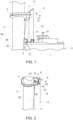
Fig. 1 shows schematic drawing of a system according to the invention comprising a ship docked at a ladderless offshore structure, -
Fig. 2 shows details of the ladderless offshore structure ofFig. 1 , and -
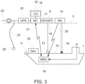
Fig. 3 is a schematic diagram of the interacting parts of the system. - Turning first to
Fig. 1 aship 1, such as a crew transfer vessel, is shown docked at anoffshore structure 2, such as a monopile foundation of a wind turbine generator. Docked in this context means that the bow ofship 1 is pressed against theoffshore structure 2, under the engine power of theship 1. For this the bow comprises afender 4 comprising materials with elastic and frictional properties suitable for keeping the bow in engagement with theoffshore structure 2 under normal circumstances without damaging theoffshore structure 2. Though the remainder of the ship may still move, the bow is relatively steady. There is, however, always a risk of the bow slipping if wind, waves or current become too excessive. - In this docked position transfers of objects, in particular persons, may take place. As will be seen the
offshore structure 2 of the system is without the conventional protective landing structure and ladder. Persons and other objects to be transferred therefore must be hoisted onto theoffshore structure 2, i.e. onto aplatform 3 arranged quite a distance above thesea surface 5. - For this a
hoisting mechanism 6 such as acrane 7 with anarm 8 extending over theedge 9 of theplatform 3 is provided. Thehoisting mechanism 6 further comprises a hoistingcable 10 with an attachment means 13 at the end for theperson 12 to be hooked onto. Hoistingcable 10 is to be understood in a broad sense and could include wires of steel, as well as cables, ropes, cords, ribbons or similar long flexible members of natural or polymer fibres suitable for the hoisting purpose. The attachment means 13 could comprise a ring or a loop that theperson 12 to be transferred may attach to or vice versa. - For the safe transfer of the
person 12 the offshore structure comprises at least one range sensing device 14 (only shown onfigure 1 ), e.g. comprising laser range sensors, located at a suitable reference point on theoffshore structure 2, e.g. on the lower side of theplatform 3, allowing them to measure the distance to the deck of theship 1, when docked at theoffshore structure 2. The measured distance, or rather data relating to the detected distance, from the reference point on saidoffshore structure 2 to theship 1, e.g. thedeck 15 thereof, is communicated in real time to acontrol device 16 on theoffshore structure 2 via awireless connection 20. Here it is received and processed, to provide an input to thecontrol mechanism 17, e.g. a motor controller for controlling an electric motor of thehoisting mechanism 6 on theoffshore structure 2. The input to the motor controller is also sent via awireless connection 21, which may or may not be the same as thewireless connection 20 used for the data relating to the detected distance. One or more of the devices, such as thecontrol device 16 and thecontrol mechanism 17, may be integrated as onesingle unit 32. - Receiving the input in real time, allows the
hoisting mechanism 6 to lift and lower the hoistingcable 10, and thereby anything attached thereto in synchronicity with the up and downward motions of theship 1, in particular thedeck 15 of theship 1, or a selected part of thedeck 15 of theship 1. This synchronicity aids in securing safe transfer, not only from theship 1 to theplatform 3, but in particular from theplatform 3 to theship 1, as risk is reduced that theship 1 may slip away below theperson 12 before he is lifted off the deck, as well as for theperson 12 to be hit by aship 1 coming up while theperson 12 is being lowered. - However, the
ship 1 may not only slip vertically but potentially also sideways or even backwards. In those cases, therange sensing device 14 loses track of thedeck 15 of theship 1. Not knowing the position of thedeck 15 in turn necessitates that theperson 12 be hoisted sufficiently far away from thedeck 15 of theship 1 to ensure that he cannot be hit by theship 1 or trapped between theship 1 and thestructure 2. - The present invention, however, reduces the risk that the
person 12 is not being hoisted away from thedeck 15 of theship 1 by automating the procedure. More specifically the present invention utilizes amotion reference unit 18 adapted to provide data relating to a detected motion of saidship 1 independently of said at least onerange sensing device 14. Thus, even if theship 1 moves out of the view of the at least onerange sensing device 14, thecontrol device 16 on theplatform 3 will still receive data on the position of theship 1, in particular a vertical reference. Accordingly, it will still be able to transmit real time data about the vertical position of theship 1, to thecontrol mechanism 17 on theplatform 3 via thewireless connection 21, and accordingly theperson 12 may still be moved up and down in synchronicity with theship 1. Even though, some security margin is preferably built into the system this security margin is much smaller than what is necessary in the prior art. - The
motion reference unit 18 may comprise any suitably kind of sensor such as accelerometers, gyroscopes, or detectors allowing the position of the ship to be determined, but may include an absoluteexternal reference 19 such as data from GNSS or differential GNSS. It may also rely on accelerometers tracking the motion of theship 1. - As mentioned above, the
offshore structure 2 is a ladderless structure. The lack of a ladder on theoffshore structure 2 and the desire to hoistpersons 12 and other objects onto theplatform 3 using ahoisting mechanism 6 following therefrom, however, involves additional problems. One in particular is the need for a power supply for thehoisting mechanism 6 including thecontrol mechanism 17 and therange sensing device 14. - If there is a power cut, e.g. failure of the
grid connection 22 of a wind turbine generator, the wind turbine generator would in a worst case scenario be left powerless and isolated. Should this happen during transfer, it would leave theperson 12 being transferred hanging helplessly in mid-air, as there is no possibility of climbing either up or down. An emergency power supply is therefore provided. Preferably, the hoisting system comprises an emergency power supply such as an uninterruptible power supply (UPS) 23, adapted to supply thehoisting system 6, therange sensing device 14,control unit 16 and thecontrol mechanism 17 for a suitable period of time, allowing theperson 12 to be hoisted safely onto theplatform 3 of theoffshore structure 2 or lowered to thedeck 15 of theship 1. - However, even though the use of a
UPS 23 may suffice for acute emergency situations, it may not be suitable for all emergencies. If the power failure has happened long before theship 1 has arrived withpersons 12 that need to be transferred, the UPS is of no use. Accordingly, another back-up power supply is provided. This back-up power supply is provided as anelectrical cable 24 that may be attached to an external power source, such as agenerator 25, by means of asuitable connector 26. - Preferably, the
electrical cable 24 is wound on aretractable cable reel 27 for automatic retraction of theelectrical cable 24 andconnector 26 towards theplatform 3. At or in the vicinity of the free end of theelectrical cable 24 where theconnector 26 is located, the cable is attached to atag line 29, which is in turn attached to theoffshore structure 2 close to thesea surface 5. Thus the tag line will be in reach from thedeck 15 of a properly dockedship 1, by aperson 30, e.g. by means of aboat hook 31. Having grabbed thetag line 29, the electrical cable can be pulled down and connected to thegenerator 25 on theship 1. Thegenerator 25 is preferably separate from the electrical system of theship 1, because the system voltages used on wind turbine generators normally differ from the system voltages used on ships. - Having connected the
hoisting mechanism 6 to thegenerator 25 thepersons 12 to be transferred, may now be transferred, preferably, but not necessarily using the motion synchronizing system described above usingrange sensors 14 and/or themotion reference unit 18. This then allowspersons 12 to enter theoffshore structure 2 after power failure, and e.g. reestablish the normal functioning of the wind turbine generator. - With this, an improved transfer system for transferring objects (such as persons) safely from a
ship 1 onto an offshore structure, such as a wind turbine generator. The skilled person will know that the system may be devised in many variants different from the exemplary embodiments explained above without departing from the scope of the claims.
Claims (10)
- A system for transferring an object (12) from a ship (1) to an offshore structure (2), said system comprising an electrically operated hoisting mechanism (6) comprising a control mechanism (2), arranged on said offshore structure (2) and adapted to move a hoisting cable (10), where the hoisting cable (19) is attached to said hoisting mechanism (6), and said hoisting cable (10) comprises an attachment means (13) adapted for attachment to said object (12),said system further comprising at least one range sensing device (14) adapted to provide real time data to a control device (16) on said offshore structure (2) relating to a detected distance from a reference point on said offshore structure (2) to said ship (1),where said system is adapted to receive said data from said at least one range sensing device (14) and to move said hoisting cable (10) in response to said detected distance,characterized in that said system further comprises a motion reference unit (18) on said ship (1) adapted to provide real time data relating to a detected motion of said ship (1) to the control mechanism (2) independently of said at least one range sensing device (14), so in thatif the range sensing device (14) loses track of said ship, said system is adapted to move said hoisting cable (10) in response to said detected motion of the ship (1),and move the object up and down in synchronicity with the ship (1).
- A system according to claim 1, wherein said motion reference unit (18) comprises at least one accelerometer.
- A system according to any one of claims 1, wherein said motion reference unit (18) comprises a receiver for external positioning data.
- A system according to any one of the preceding claims, further comprising an emergency power supply for said electrically operated hoisting mechanism (6).
- A system according to claim 4, wherein said emergency power supply comprises an uninterruptable power supply (23).
- A system according to any one of the preceding claims, wherein said offshore structure further comprises an electrical emergency power supply cable (24) attachable to an external power source.
- A system according to claim 6, wherein the external power source is a generator (25) on the ship (1).
- A system according to claim 7, wherein the generator (25) is independent of the electrical system of the ship (1).
- A system according to any one of the preceding claims, wherein said hoisting mechanism (6) comprises a crane arm (7).
- A method for transferring an object (12) from a ship (1) to an offshore structure (2), wherein a system according to any one of the preceding claims is used.
Applications Claiming Priority (2)
| Application Number | Priority Date | Filing Date | Title |
|---|---|---|---|
| EP18207102.7A EP3653484A1 (en) | 2018-11-19 | 2018-11-19 | A system for transferring an object from a ship to an offshore structure |
| PCT/EP2019/079060 WO2020104137A1 (en) | 2018-11-19 | 2019-10-24 | A system for transferring an object from a ship to an offshore structure |
Publications (2)
| Publication Number | Publication Date |
|---|---|
| EP3883848A1 EP3883848A1 (en) | 2021-09-29 |
| EP3883848B1 true EP3883848B1 (en) | 2025-04-02 |
Family
ID=64362461
Family Applications (2)
| Application Number | Title | Priority Date | Filing Date |
|---|---|---|---|
| EP18207102.7A Withdrawn EP3653484A1 (en) | 2018-11-19 | 2018-11-19 | A system for transferring an object from a ship to an offshore structure |
| EP19790010.3A Active EP3883848B1 (en) | 2018-11-19 | 2019-10-24 | A system for transferring an object from a ship to an offshore structure |
Family Applications Before (1)
| Application Number | Title | Priority Date | Filing Date |
|---|---|---|---|
| EP18207102.7A Withdrawn EP3653484A1 (en) | 2018-11-19 | 2018-11-19 | A system for transferring an object from a ship to an offshore structure |
Country Status (9)
| Country | Link |
|---|---|
| US (1) | US12054368B2 (en) |
| EP (2) | EP3653484A1 (en) |
| JP (1) | JP7367019B2 (en) |
| KR (1) | KR102770417B1 (en) |
| DK (1) | DK3883848T3 (en) |
| ES (1) | ES3028255T3 (en) |
| PL (1) | PL3883848T3 (en) |
| TW (2) | TW202306839A (en) |
| WO (1) | WO2020104137A1 (en) |
Families Citing this family (5)
| Publication number | Priority date | Publication date | Assignee | Title |
|---|---|---|---|---|
| EP4328125A1 (en) * | 2022-08-25 | 2024-02-28 | Ørsted Wind Power A/S | Marine transfer apparatus and method of using the same |
| KR102609806B1 (en) * | 2023-05-16 | 2023-12-05 | 주식회사 오리엔탈정공 | Emergency power pack for a crane |
| GB2630132A (en) * | 2023-05-19 | 2024-11-20 | Iwave Systems Ltd | Offshore crew transfer |
| CN119840784B (en) * | 2025-01-14 | 2025-11-14 | 哈尔滨工程大学 | An unmanned barge operation device, method, and supply vessel |
| CN120162663B (en) * | 2025-02-14 | 2025-11-11 | 广州飞曙电子科技有限公司 | Data analysis method, device, equipment and medium for marine leaning behavior |
Family Cites Families (14)
| Publication number | Priority date | Publication date | Assignee | Title |
|---|---|---|---|---|
| US5089972A (en) * | 1990-12-13 | 1992-02-18 | Nachman Precision Systems, Inc. | Moored ship motion determination system |
| KR101029771B1 (en) | 2010-07-30 | 2011-04-19 | 에스에이지주식회사 | Eyepieces for offshore wind power plants |
| CA2773190A1 (en) * | 2011-04-11 | 2012-10-11 | Envision Energy (Denmark) Aps | Offshore wind turbine comprising a support system for interchangeable containers with a wave run-up deflector |
| DE102011102025A1 (en) * | 2011-05-19 | 2012-11-22 | Liebherr-Werk Nenzing Gmbh | crane control |
| WO2012161584A1 (en) * | 2011-05-20 | 2012-11-29 | Optilift As | System, device and method for tracking position and orientation of vehicle, loading device and cargo in loading device operations |
| DE202011051271U1 (en) * | 2011-07-28 | 2012-11-07 | Emco Wheaton Gmbh | OFFSHORE LOADING SYSTEM |
| EP2855331B1 (en) * | 2012-06-01 | 2018-12-26 | Seatrax, Inc. | System and method to determine relative velocity of crane and target load |
| KR20140054530A (en) * | 2012-10-29 | 2014-05-09 | 대우조선해양 주식회사 | Power supply system of offshore plant and method thereof |
| JP5984642B2 (en) | 2012-11-28 | 2016-09-06 | 住友重機械搬送システム株式会社 | Crane damping control system and crane damping control method |
| GB201303031D0 (en) | 2013-02-21 | 2013-04-03 | Limpet Holdings Uk Ltd | Improved appratus for and method of transferring an object between a marine transport vessel and a construction or vessel |
| WO2015044898A1 (en) * | 2013-09-27 | 2015-04-02 | Rolls-Royce Canada, Ltd. | Two body motion compensation system for marine applications |
| KR20160041595A (en) * | 2014-10-08 | 2016-04-18 | 대우조선해양 주식회사 | Power distribution system of floating marine structure of method for distributing power using the same |
| SG10201608235YA (en) | 2015-10-05 | 2017-05-30 | Keppel Offshore & Marine Technology Ct Pte Ltd | System and method for guiding cargo transfer between two bodies |
| CN106495027B (en) * | 2016-12-27 | 2020-03-10 | 江苏金风科技有限公司 | Method and system for hoisting and unloading goods with automatic wave compensation and crane platform |
-
2018
- 2018-11-19 EP EP18207102.7A patent/EP3653484A1/en not_active Withdrawn
-
2019
- 2019-10-24 US US17/293,692 patent/US12054368B2/en active Active
- 2019-10-24 PL PL19790010.3T patent/PL3883848T3/en unknown
- 2019-10-24 WO PCT/EP2019/079060 patent/WO2020104137A1/en not_active Ceased
- 2019-10-24 ES ES19790010T patent/ES3028255T3/en active Active
- 2019-10-24 KR KR1020217014693A patent/KR102770417B1/en active Active
- 2019-10-24 DK DK19790010.3T patent/DK3883848T3/en active
- 2019-10-24 EP EP19790010.3A patent/EP3883848B1/en active Active
- 2019-10-24 JP JP2021527226A patent/JP7367019B2/en active Active
- 2019-11-07 TW TW111134781A patent/TW202306839A/en unknown
- 2019-11-07 TW TW108140507A patent/TW202021864A/en unknown
Also Published As
| Publication number | Publication date |
|---|---|
| ES3028255T3 (en) | 2025-06-18 |
| WO2020104137A1 (en) | 2020-05-28 |
| DK3883848T3 (en) | 2025-05-26 |
| TW202021864A (en) | 2020-06-16 |
| JP7367019B2 (en) | 2023-10-23 |
| EP3883848A1 (en) | 2021-09-29 |
| JP2022510582A (en) | 2022-01-27 |
| TW202306839A (en) | 2023-02-16 |
| EP3653484A1 (en) | 2020-05-20 |
| US12054368B2 (en) | 2024-08-06 |
| KR20210092747A (en) | 2021-07-26 |
| PL3883848T3 (en) | 2025-06-16 |
| KR102770417B1 (en) | 2025-02-21 |
| US20220002121A1 (en) | 2022-01-06 |
Similar Documents
| Publication | Publication Date | Title |
|---|---|---|
| US12054368B2 (en) | System for transferring an object from a ship to an offshore structure | |
| CN104114445B (en) | Lift the method for goods and materials, reclaim the system and surface supporting vessel of goods and materials | |
| US8959694B2 (en) | Bridge apparatus | |
| JP6591044B2 (en) | Unmanned vessel recovery coupling device and coupling control method using the same | |
| JP6538569B2 (en) | Improved apparatus and method for transferring objects between sea transport vessels and structures or vessels | |
| WO2011095316A1 (en) | A method of transferring a load between a vessel and a wind turbine, and a wind turbine | |
| WO2016205856A1 (en) | A system and method for retrieving a vessel from water | |
| TWI879783B (en) | Marine transfer apparatus and method of using the same | |
| EP4328125A1 (en) | Marine transfer apparatus and method of using the same | |
| WO2012163957A1 (en) | A launch and retrieval system | |
| CN119049247B (en) | Ocean buoy emergency positioning device and method |
Legal Events
| Date | Code | Title | Description |
|---|---|---|---|
| STAA | Information on the status of an ep patent application or granted ep patent |
Free format text: STATUS: UNKNOWN |
|
| STAA | Information on the status of an ep patent application or granted ep patent |
Free format text: STATUS: THE INTERNATIONAL PUBLICATION HAS BEEN MADE |
|
| PUAI | Public reference made under article 153(3) epc to a published international application that has entered the european phase |
Free format text: ORIGINAL CODE: 0009012 |
|
| STAA | Information on the status of an ep patent application or granted ep patent |
Free format text: STATUS: REQUEST FOR EXAMINATION WAS MADE |
|
| 17P | Request for examination filed |
Effective date: 20210602 |
|
| AK | Designated contracting states |
Kind code of ref document: A1 Designated state(s): AL AT BE BG CH CY CZ DE DK EE ES FI FR GB GR HR HU IE IS IT LI LT LU LV MC MK MT NL NO PL PT RO RS SE SI SK SM TR |
|
| DAV | Request for validation of the european patent (deleted) | ||
| DAX | Request for extension of the european patent (deleted) | ||
| STAA | Information on the status of an ep patent application or granted ep patent |
Free format text: STATUS: EXAMINATION IS IN PROGRESS |
|
| 17Q | First examination report despatched |
Effective date: 20230609 |
|
| GRAP | Despatch of communication of intention to grant a patent |
Free format text: ORIGINAL CODE: EPIDOSNIGR1 |
|
| STAA | Information on the status of an ep patent application or granted ep patent |
Free format text: STATUS: GRANT OF PATENT IS INTENDED |
|
| RAP1 | Party data changed (applicant data changed or rights of an application transferred) |
Owner name: PICT OFFSHORE LTD |
|
| INTG | Intention to grant announced |
Effective date: 20241024 |
|
| GRAS | Grant fee paid |
Free format text: ORIGINAL CODE: EPIDOSNIGR3 |
|
| GRAA | (expected) grant |
Free format text: ORIGINAL CODE: 0009210 |
|
| STAA | Information on the status of an ep patent application or granted ep patent |
Free format text: STATUS: THE PATENT HAS BEEN GRANTED |
|
| AK | Designated contracting states |
Kind code of ref document: B1 Designated state(s): AL AT BE BG CH CY CZ DE DK EE ES FI FR GB GR HR HU IE IS IT LI LT LU LV MC MK MT NL NO PL PT RO RS SE SI SK SM TR |
|
| REG | Reference to a national code |
Ref country code: GB Ref legal event code: FG4D |
|
| REG | Reference to a national code |
Ref country code: CH Ref legal event code: EP |
|
| REG | Reference to a national code |
Ref country code: IE Ref legal event code: FG4D |
|
| REG | Reference to a national code |
Ref country code: DE Ref legal event code: R096 Ref document number: 602019068149 Country of ref document: DE |
|
| REG | Reference to a national code |
Ref country code: DK Ref legal event code: T3 Effective date: 20250522 |
|
| REG | Reference to a national code |
Ref country code: NL Ref legal event code: FP |
|
| REG | Reference to a national code |
Ref country code: SE Ref legal event code: TRGR |
|
| REG | Reference to a national code |
Ref country code: ES Ref legal event code: FG2A Ref document number: 3028255 Country of ref document: ES Kind code of ref document: T3 Effective date: 20250618 |
|
| REG | Reference to a national code |
Ref country code: AT Ref legal event code: MK05 Ref document number: 1781074 Country of ref document: AT Kind code of ref document: T Effective date: 20250402 |
|
| PG25 | Lapsed in a contracting state [announced via postgrant information from national office to epo] |
Ref country code: PT Free format text: LAPSE BECAUSE OF FAILURE TO SUBMIT A TRANSLATION OF THE DESCRIPTION OR TO PAY THE FEE WITHIN THE PRESCRIBED TIME-LIMIT Effective date: 20250804 Ref country code: FI Free format text: LAPSE BECAUSE OF FAILURE TO SUBMIT A TRANSLATION OF THE DESCRIPTION OR TO PAY THE FEE WITHIN THE PRESCRIBED TIME-LIMIT Effective date: 20250402 |
|
| REG | Reference to a national code |
Ref country code: LT Ref legal event code: MG9D |
|
| PG25 | Lapsed in a contracting state [announced via postgrant information from national office to epo] |
Ref country code: GR Free format text: LAPSE BECAUSE OF FAILURE TO SUBMIT A TRANSLATION OF THE DESCRIPTION OR TO PAY THE FEE WITHIN THE PRESCRIBED TIME-LIMIT Effective date: 20250703 |
|
| PG25 | Lapsed in a contracting state [announced via postgrant information from national office to epo] |
Ref country code: BG Free format text: LAPSE BECAUSE OF FAILURE TO SUBMIT A TRANSLATION OF THE DESCRIPTION OR TO PAY THE FEE WITHIN THE PRESCRIBED TIME-LIMIT Effective date: 20250402 |
|
| PG25 | Lapsed in a contracting state [announced via postgrant information from national office to epo] |
Ref country code: HR Free format text: LAPSE BECAUSE OF FAILURE TO SUBMIT A TRANSLATION OF THE DESCRIPTION OR TO PAY THE FEE WITHIN THE PRESCRIBED TIME-LIMIT Effective date: 20250402 |
|
| PG25 | Lapsed in a contracting state [announced via postgrant information from national office to epo] |
Ref country code: AT Free format text: LAPSE BECAUSE OF FAILURE TO SUBMIT A TRANSLATION OF THE DESCRIPTION OR TO PAY THE FEE WITHIN THE PRESCRIBED TIME-LIMIT Effective date: 20250402 |
|
| PG25 | Lapsed in a contracting state [announced via postgrant information from national office to epo] |
Ref country code: RS Free format text: LAPSE BECAUSE OF FAILURE TO SUBMIT A TRANSLATION OF THE DESCRIPTION OR TO PAY THE FEE WITHIN THE PRESCRIBED TIME-LIMIT Effective date: 20250702 |
|
| PG25 | Lapsed in a contracting state [announced via postgrant information from national office to epo] |
Ref country code: IS Free format text: LAPSE BECAUSE OF FAILURE TO SUBMIT A TRANSLATION OF THE DESCRIPTION OR TO PAY THE FEE WITHIN THE PRESCRIBED TIME-LIMIT Effective date: 20250802 |
|
| PG25 | Lapsed in a contracting state [announced via postgrant information from national office to epo] |
Ref country code: LV Free format text: LAPSE BECAUSE OF FAILURE TO SUBMIT A TRANSLATION OF THE DESCRIPTION OR TO PAY THE FEE WITHIN THE PRESCRIBED TIME-LIMIT Effective date: 20250402 |
|
| PGFP | Annual fee paid to national office [announced via postgrant information from national office to epo] |
Ref country code: NL Payment date: 20251020 Year of fee payment: 7 |
|
| REG | Reference to a national code |
Ref country code: DE Ref legal event code: R097 Ref document number: 602019068149 Country of ref document: DE |
|
| PGFP | Annual fee paid to national office [announced via postgrant information from national office to epo] |
Ref country code: DE Payment date: 20251015 Year of fee payment: 7 |
|
| PGFP | Annual fee paid to national office [announced via postgrant information from national office to epo] |
Ref country code: GB Payment date: 20251009 Year of fee payment: 7 |
|
| PGFP | Annual fee paid to national office [announced via postgrant information from national office to epo] |
Ref country code: NO Payment date: 20251022 Year of fee payment: 7 |
|
| PG25 | Lapsed in a contracting state [announced via postgrant information from national office to epo] |
Ref country code: SM Free format text: LAPSE BECAUSE OF FAILURE TO SUBMIT A TRANSLATION OF THE DESCRIPTION OR TO PAY THE FEE WITHIN THE PRESCRIBED TIME-LIMIT Effective date: 20250402 |
|
| PGFP | Annual fee paid to national office [announced via postgrant information from national office to epo] |
Ref country code: DK Payment date: 20251020 Year of fee payment: 7 Ref country code: IT Payment date: 20251014 Year of fee payment: 7 |
|
| PGFP | Annual fee paid to national office [announced via postgrant information from national office to epo] |
Ref country code: FR Payment date: 20251022 Year of fee payment: 7 |
|
| PGFP | Annual fee paid to national office [announced via postgrant information from national office to epo] |
Ref country code: BE Payment date: 20251015 Year of fee payment: 7 |
|
| PGFP | Annual fee paid to national office [announced via postgrant information from national office to epo] |
Ref country code: SE Payment date: 20251021 Year of fee payment: 7 |
|
| PG25 | Lapsed in a contracting state [announced via postgrant information from national office to epo] |
Ref country code: CZ Free format text: LAPSE BECAUSE OF FAILURE TO SUBMIT A TRANSLATION OF THE DESCRIPTION OR TO PAY THE FEE WITHIN THE PRESCRIBED TIME-LIMIT Effective date: 20250402 |
|
| PGFP | Annual fee paid to national office [announced via postgrant information from national office to epo] |
Ref country code: IE Payment date: 20251020 Year of fee payment: 7 |
|
| PGFP | Annual fee paid to national office [announced via postgrant information from national office to epo] |
Ref country code: PL Payment date: 20251014 Year of fee payment: 7 |
|
| PG25 | Lapsed in a contracting state [announced via postgrant information from national office to epo] |
Ref country code: EE Free format text: LAPSE BECAUSE OF FAILURE TO SUBMIT A TRANSLATION OF THE DESCRIPTION OR TO PAY THE FEE WITHIN THE PRESCRIBED TIME-LIMIT Effective date: 20250402 |
|
| PG25 | Lapsed in a contracting state [announced via postgrant information from national office to epo] |
Ref country code: SK Free format text: LAPSE BECAUSE OF FAILURE TO SUBMIT A TRANSLATION OF THE DESCRIPTION OR TO PAY THE FEE WITHIN THE PRESCRIBED TIME-LIMIT Effective date: 20250402 Ref country code: RO Free format text: LAPSE BECAUSE OF FAILURE TO SUBMIT A TRANSLATION OF THE DESCRIPTION OR TO PAY THE FEE WITHIN THE PRESCRIBED TIME-LIMIT Effective date: 20250402 |
|
| PGFP | Annual fee paid to national office [announced via postgrant information from national office to epo] |
Ref country code: ES Payment date: 20251107 Year of fee payment: 7 |
|
| PLBE | No opposition filed within time limit |
Free format text: ORIGINAL CODE: 0009261 |
|
| STAA | Information on the status of an ep patent application or granted ep patent |
Free format text: STATUS: NO OPPOSITION FILED WITHIN TIME LIMIT |
|
| REG | Reference to a national code |
Ref country code: CH Ref legal event code: L10 Free format text: ST27 STATUS EVENT CODE: U-0-0-L10-L00 (AS PROVIDED BY THE NATIONAL OFFICE) Effective date: 20260211 |
|
| 26N | No opposition filed |
Effective date: 20260105 |