EP3883629B1 - E-vaping device and components thereof - Google Patents
E-vaping device and components thereof Download PDFInfo
- Publication number
- EP3883629B1 EP3883629B1 EP19808570.6A EP19808570A EP3883629B1 EP 3883629 B1 EP3883629 B1 EP 3883629B1 EP 19808570 A EP19808570 A EP 19808570A EP 3883629 B1 EP3883629 B1 EP 3883629B1
- Authority
- EP
- European Patent Office
- Prior art keywords
- assembly
- reservoir
- bayonet
- vaporizer
- bayonet connector
- Prior art date
- Legal status (The legal status is an assumption and is not a legal conclusion. Google has not performed a legal analysis and makes no representation as to the accuracy of the status listed.)
- Active
Links
Images






Classifications
-
- A—HUMAN NECESSITIES
- A24—TOBACCO; CIGARS; CIGARETTES; SIMULATED SMOKING DEVICES; SMOKERS' REQUISITES
- A24F—SMOKERS' REQUISITES; MATCH BOXES; SIMULATED SMOKING DEVICES
- A24F40/00—Electrically operated smoking devices; Component parts thereof; Manufacture thereof; Maintenance or testing thereof; Charging means specially adapted therefor
- A24F40/40—Constructional details, e.g. connection of cartridges and battery parts
- A24F40/42—Cartridges or containers for inhalable precursors
-
- A—HUMAN NECESSITIES
- A61—MEDICAL OR VETERINARY SCIENCE; HYGIENE
- A61M—DEVICES FOR INTRODUCING MEDIA INTO, OR ONTO, THE BODY; DEVICES FOR TRANSDUCING BODY MEDIA OR FOR TAKING MEDIA FROM THE BODY; DEVICES FOR PRODUCING OR ENDING SLEEP OR STUPOR
- A61M15/00—Inhalators
- A61M15/06—Inhaling appliances shaped like cigars, cigarettes or pipes
-
- A—HUMAN NECESSITIES
- A24—TOBACCO; CIGARS; CIGARETTES; SIMULATED SMOKING DEVICES; SMOKERS' REQUISITES
- A24F—SMOKERS' REQUISITES; MATCH BOXES; SIMULATED SMOKING DEVICES
- A24F40/00—Electrically operated smoking devices; Component parts thereof; Manufacture thereof; Maintenance or testing thereof; Charging means specially adapted therefor
- A24F40/40—Constructional details, e.g. connection of cartridges and battery parts
- A24F40/48—Fluid transfer means, e.g. pumps
- A24F40/485—Valves; Apertures
-
- A—HUMAN NECESSITIES
- A24—TOBACCO; CIGARS; CIGARETTES; SIMULATED SMOKING DEVICES; SMOKERS' REQUISITES
- A24F—SMOKERS' REQUISITES; MATCH BOXES; SIMULATED SMOKING DEVICES
- A24F15/00—Receptacles or boxes specially adapted for cigars, cigarettes, simulated smoking devices or cigarettes therefor
- A24F15/01—Receptacles or boxes specially adapted for cigars, cigarettes, simulated smoking devices or cigarettes therefor specially adapted for simulated smoking devices or cigarettes therefor
- A24F15/015—Receptacles or boxes specially adapted for cigars, cigarettes, simulated smoking devices or cigarettes therefor specially adapted for simulated smoking devices or cigarettes therefor with means for refilling of liquid inhalable precursors
-
- A—HUMAN NECESSITIES
- A24—TOBACCO; CIGARS; CIGARETTES; SIMULATED SMOKING DEVICES; SMOKERS' REQUISITES
- A24F—SMOKERS' REQUISITES; MATCH BOXES; SIMULATED SMOKING DEVICES
- A24F40/00—Electrically operated smoking devices; Component parts thereof; Manufacture thereof; Maintenance or testing thereof; Charging means specially adapted therefor
- A24F40/10—Devices using liquid inhalable precursors
-
- A—HUMAN NECESSITIES
- A24—TOBACCO; CIGARS; CIGARETTES; SIMULATED SMOKING DEVICES; SMOKERS' REQUISITES
- A24F—SMOKERS' REQUISITES; MATCH BOXES; SIMULATED SMOKING DEVICES
- A24F40/00—Electrically operated smoking devices; Component parts thereof; Manufacture thereof; Maintenance or testing thereof; Charging means specially adapted therefor
- A24F40/40—Constructional details, e.g. connection of cartridges and battery parts
-
- A—HUMAN NECESSITIES
- A24—TOBACCO; CIGARS; CIGARETTES; SIMULATED SMOKING DEVICES; SMOKERS' REQUISITES
- A24F—SMOKERS' REQUISITES; MATCH BOXES; SIMULATED SMOKING DEVICES
- A24F40/00—Electrically operated smoking devices; Component parts thereof; Manufacture thereof; Maintenance or testing thereof; Charging means specially adapted therefor
- A24F40/70—Manufacture
-
- A—HUMAN NECESSITIES
- A61—MEDICAL OR VETERINARY SCIENCE; HYGIENE
- A61M—DEVICES FOR INTRODUCING MEDIA INTO, OR ONTO, THE BODY; DEVICES FOR TRANSDUCING BODY MEDIA OR FOR TAKING MEDIA FROM THE BODY; DEVICES FOR PRODUCING OR ENDING SLEEP OR STUPOR
- A61M11/00—Sprayers or atomisers specially adapted for therapeutic purposes
- A61M11/04—Sprayers or atomisers specially adapted for therapeutic purposes operated by the vapour pressure of the liquid to be sprayed or atomised
- A61M11/041—Sprayers or atomisers specially adapted for therapeutic purposes operated by the vapour pressure of the liquid to be sprayed or atomised using heaters
- A61M11/042—Sprayers or atomisers specially adapted for therapeutic purposes operated by the vapour pressure of the liquid to be sprayed or atomised using heaters electrical
-
- A—HUMAN NECESSITIES
- A61—MEDICAL OR VETERINARY SCIENCE; HYGIENE
- A61M—DEVICES FOR INTRODUCING MEDIA INTO, OR ONTO, THE BODY; DEVICES FOR TRANSDUCING BODY MEDIA OR FOR TAKING MEDIA FROM THE BODY; DEVICES FOR PRODUCING OR ENDING SLEEP OR STUPOR
- A61M2205/00—General characteristics of the apparatus
- A61M2205/60—General characteristics of the apparatus with identification means
- A61M2205/6045—General characteristics of the apparatus with identification means having complementary physical shapes for indexing or registration purposes
-
- A—HUMAN NECESSITIES
- A61—MEDICAL OR VETERINARY SCIENCE; HYGIENE
- A61M—DEVICES FOR INTRODUCING MEDIA INTO, OR ONTO, THE BODY; DEVICES FOR TRANSDUCING BODY MEDIA OR FOR TAKING MEDIA FROM THE BODY; DEVICES FOR PRODUCING OR ENDING SLEEP OR STUPOR
- A61M2209/00—Ancillary equipment
- A61M2209/04—Tools for specific apparatus
- A61M2209/045—Tools for specific apparatus for filling, e.g. for filling reservoirs
-
- H—ELECTRICITY
- H01—ELECTRIC ELEMENTS
- H01M—PROCESSES OR MEANS, e.g. BATTERIES, FOR THE DIRECT CONVERSION OF CHEMICAL ENERGY INTO ELECTRICAL ENERGY
- H01M2220/00—Batteries for particular applications
- H01M2220/30—Batteries in portable systems, e.g. mobile phone, laptop
-
- Y—GENERAL TAGGING OF NEW TECHNOLOGICAL DEVELOPMENTS; GENERAL TAGGING OF CROSS-SECTIONAL TECHNOLOGIES SPANNING OVER SEVERAL SECTIONS OF THE IPC; TECHNICAL SUBJECTS COVERED BY FORMER USPC CROSS-REFERENCE ART COLLECTIONS [XRACs] AND DIGESTS
- Y02—TECHNOLOGIES OR APPLICATIONS FOR MITIGATION OR ADAPTATION AGAINST CLIMATE CHANGE
- Y02E—REDUCTION OF GREENHOUSE GAS [GHG] EMISSIONS, RELATED TO ENERGY GENERATION, TRANSMISSION OR DISTRIBUTION
- Y02E60/00—Enabling technologies; Technologies with a potential or indirect contribution to GHG emissions mitigation
- Y02E60/10—Energy storage using batteries
Definitions
- Example embodiments relate to electronic vaping devices, e-vaping devices, or the like, and components thereof.
- E-vaping devices also referred to herein as electronic vaping devices (EVDs) may be used by adult vapers for fluid portable vaping.
- An e-vaping device may include a reservoir that holds pre-vapor formulation and a vaporizer assembly that may heat pre-vapor formulation drawn from the reservoir to generate a vapor.
- Some e-vaping devices are configured to enable replenishment of the pre-vapor formulation held in a reservoir of the e-vaping device (that is, refilling of the reservoir).
- US 2017/071251 A1 describes a smoking device comprising a liquid evaporator comprising a liquid reservoir, a wick and a liquid-heating device.
- the device also comprises a tobacco heater comprising a chamber for receiving tobacco and a chamber-heating device for heating the tobacco in the chamber.
- a tobacco-flow channel carries vapor from the tobacco in the chamber through the liquid reservoir to the wick where it combines with liquid vapor, the combined vapor then being discharged via a liquid flow-channel through an intake-opening arrangement, which is the part of the device from which the user takes in the vapor from the device.
- the intake-opening arrangement may also be referred to as the outlet of the device.
- the device of US 2017/071251 A1 has a modular arrangement, with the liquid evaporator forming part of a liquid-evaporator module and the tobacco heater forming part of a tobacco-heater module.
- the liquid-evaporator module comprises an evaporator-connecting arrangement for connecting to a heater-connecting arrangement of the tobacco-heater module using a bayonet connection.
- the liquid-evaporator module and the tobacco-heater module comprise bayonet connections at both ends, so that the positions of the liquid evaporator module and the tobacco-heater module may be swapped.
- US 2017/071251 A1 describes a mouthpiece module that may be attached to either the liquid-evaporator module or the tobacco-heater module via the bayonet connection.
- a reservoir assembly for an e-vaping device the reservoir assembly according to claim 1.
- the conduit may extend from a vaporizer assembly.
- the vaporizer assembly may be in fluid communication with the exterior of the reservoir assembly through the interior of the outlet assembly when the bayonet interface connection is established.
- the conduit may extend through the space defined by the first bayonet connector assembly.
- the first bayonet connector assembly may include a bayonet plug connector element and may be configured to detachably couple with a complementary bayonet receptacle connector element of the second bayonet connector assembly to establish the bayonet interface connection.
- the reservoir assembly may further include a vaporizer connector assembly configured to detachably couple the reservoir with the vaporizer assembly.
- An end of the conduit may be coupled to the vaporizer connector assembly, such that the conduit is configured to couple with the vaporizer assembly via the vaporizer connector assembly.
- the first bayonet connector assembly may be directly coupled to the end of the reservoir.
- a vapor generator assembly for an e-vaping device, the vapor generator assembly according to claim 7.
- the vaporizer assembly may be in fluid communication with the exterior of the vapor generator assembly through the interior of the outlet assembly when the bayonet interface connection is established.
- the conduit may extend through the space defined by the first bayonet connector assembly.
- the first bayonet connector assembly may include a bayonet plug connector and may be configured to detachably couple with a bayonet receptacle connector of the second bayonet connector assembly to establish the bayonet interface connection.
- the vapor generator assembly may include a vaporizer connector assembly, wherein the reservoir is detachably coupled with the vaporizer assembly through the vaporizer connector assembly.
- An end of the conduit may be coupled to the vaporizer connector assembly, such that the conduit is coupled with the vaporizer assembly via the vaporizer connector assembly.
- the first bayonet connector assembly may be directly coupled to the end of the reservoir.
- an e-vaping device according to claim 13.
- the vaporizer assembly may be in fluid communication with the exterior of the vapor generator assembly through the interior of the outlet assembly when the bayonet interface connection is established.
- the conduit may extend through the space defined by the first bayonet connector assembly.
- the first bayonet connector assembly may include a bayonet plug connector and may be configured to detachably couple with a bayonet receptacle connector of the second bayonet connector assembly to establish the bayonet interface connection.
- the first bayonet connector assembly may be directly coupled to the end of the reservoir.
- the power supply assembly may include a rechargeable battery.
- the power supply assembly may be detachably coupled with the vapor generator assembly.
- the e-vaping device may include a vaporizer connector assembly.
- the reservoir may be detachably coupled with the vaporizer assembly through the vaporizer connector assembly.
- An end of the conduit may be coupled to a vaporizer connector assembly, such that the conduit is coupled with the vaporizer assembly via the vaporizer connector assembly.
- first, second, third, and so forth may be used herein to describe various elements, components, regions, layers or sections, these elements, components, regions, layers, or sections should not be limited by these terms. These terms are only used to distinguish one element, component, region, layer, or section from another region, layer, or section. Therefore, a first element, component, region, layer, or section discussed below could be termed a second element, component, region, layer, or section without departing from the teachings of example embodiments.
- spatially relative terms for example, “beneath,” “below,” “lower,” “above,” “upper,” and the like
- the spatially relative terms are intended to encompass different orientations of the device in use or operation in addition to the orientation depicted in the figures. For example, if the device in the figures is turned over, elements described as “below” or “beneath” other elements or features would then be oriented “above” the other elements or features. Therefore, the term “below” may encompass both an orientation of above and below.
- the device may be otherwise oriented (rotated 90 degrees or at other orientations) and the spatially relative descriptors used herein interpreted accordingly.
- Example embodiments are described herein with reference to cross-sectional illustrations that are schematic illustrations of example embodiments. As such, variations from the shapes of the illustrations are to be expected. Therefore, example embodiments should not be construed as limited to the shapes of regions illustrated herein but are to include deviations in shapes.
- Vapor, aerosol and dispersion are used interchangeably and are meant to cover the matter generated or outputted by the devices disclosed, claimed and equivalents thereof.
- Hardware may be implemented using processing or control circuitry such as, but not limited to, one or more processors, one or more Central Processing Units (CPUs), one or more microcontrollers, one or more arithmetic logic units (ALUs), one or more digital signal processors (DSPs), one or more microcomputers, one or more field programmable gate arrays (FPGAs), one or more System-on-Chips (SoCs), one or more programmable logic units (PLUs), one or more microprocessors, one or more Application Specific Integrated Circuits (ASICs), or any other device or devices capable of responding to and executing instructions in a defined manner.
- processors such as, but not limited to, one or more processors, one or more Central Processing Units (CPUs), one or more microcontrollers, one or more arithmetic logic units (ALUs), one or more digital signal processors (DSPs), one or more microcomputers, one or more field programmable gate arrays (FPGAs), one or more System-
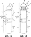
- FIG. 1A is a perspective view of an e-vaping device 100 according to some example embodiments.
- FIG. 1B is a perspective view of an e-vaping device 100 according to some example embodiments.
- FIG. 1C is a cross-sectional view along line IC-IC' of the e-vaping device 100 of FIG. 1A according to some example embodiments.
- FIG. 1D is a cross-sectional view along line ID-ID' of the e-vaping device 100 of FIG. 1B according to some example embodiments.
- the term "e-vaping device” is inclusive of all types of electronic vaping devices, regardless of form, size or shape.
- the e-vaping device 100 includes a vapor generator assembly 110 and power supply assembly 120.
- a vapor generator assembly 110 that is configured to be detachably coupled to a power supply assembly 120 to form an e-vaping device 100 may be referred to herein as a cartridge.
- the vapor generator assembly 110 and power supply assembly 120 include respective complementary connector assemblies 118, 128 and are configured to be detachably connected to each other based on detachably coupling the connector assemblies 118, 128 together.
- the connector assemblies 118, 128 include threaded connectors. It should be appreciated that a connector assembly 118, 128 may be any type of connector, including, without limitation, a snug-fit, detent, clamp, bayonet, sliding fit, sleeve fit, alignment fit, threaded connector, magnetic, clasp, or any other type of connection, and combinations thereof.
- the vapor generator assembly 110 may include an outer housing 111
- the power supply assembly 120 may include an outer housing 121, where the outer housing 111 and the outer housing 121 may collectively define an outer housing 191 of the e-vaping device 100.
- the vapor generator assembly 110 may include a reservoir 112, a vaporizer assembly 130, a first bayonet connector assembly 117 and an outlet assembly 150, where the outlet assembly 150 includes a second bayonet connector assembly 157.
- Structures of a first and second bayonet connector assemblies 117, 157 according to example embodiments are described further below with reference to FIGS. 2A-2B , 3A-3B , 4A-4D , 5A-5D , 6A-6C , 7A-7C , 8A-8G , and 9A-9C .
- a reservoir 112 may be included in a reservoir assembly 102 of some example embodiments.
- the outer housing 111 of the vapor generator assembly 110 may include an outer housing 113 of the reservoir 112 and an outer housing 131 of the vaporizer assembly 130, where outer housings 113 and 131 collectively define the outer housing 111.
- housings 113 and 131 are separate connectable housings, and in some example embodiments housings 113 and 131 form part of the same housing.
- the outer housing 113 of the reservoir 112 may at least partially define an interior space 115.
- the reservoir 112 may be configured to hold a pre-vapor formulation within the interior of the reservoir 112, where the interior may include the interior space 115 at least partially defined by the outer housing 113 of the reservoir 112.
- the reservoir 112 may include a fluid port 114 which extends through the outer housing 113 of the reservoir 112 between the interior space 115 of the reservoir 112 and an exterior of at least the reservoir 112, such that the fluid port 114 is in fluid communication with the exterior of at least the reservoir 112 and thereby may enable fluid communication between the reservoir 112 and the exterior of at least the reservoir 112.
- the vaporizer assembly 130 and reservoir 112 include respective complementary connector assemblies 138, 148 and are configured to be detachably connected to each other based on detachably coupling the connector assemblies 138, 148 together.
- the vaporizer connector assembly 148 may be configured to detachably couple the reservoir 112 with the vaporizer assembly 130, for example based on detachably coupling with the connector assembly 138 of the vaporizer assembly 130.
- the connector assemblies 138, 148 include threaded connectors.
- a connector assembly 138, 148 may be any type of connector, including, without limitation, a snug-fit, detent, clamp, bayonet, sliding fit, sleeve fit, alignment fit, threaded connector, magnetic, clasp, or any other type of connection, and combinations thereof.
- the vaporizer assembly 130 may include an outer housing 131 that at least partially defines an interior space 135 of the vaporizer assembly 130.
- the vaporizer assembly 130 may include a fluid port 134 which extends through the outer housing 131 of the vaporizer assembly 130 between the interior space 135 of the vaporizer assembly 130 and an exterior of the vaporizer assembly 130, such that the fluid port 134 may enable fluid communication between the interior space 135 and an exterior of the vaporizer assembly 130.
- the fluid port 134 may enable fluid communication between the reservoir 112 and the vaporizer assembly 130.
- the fluid port 134 extends through the outer housing 113 of the reservoir 112, in addition to or instead of extending through the outer housing 131 of the vaporizer assembly 130.
- housing 113 meets with housing 131 may form part of the same housing, or these may be two separate housings that can be connected together (for example, via complementary connector assemblies 138, 148).
- fluid port 114 may include more than one port (for example, there may be multiple first fluid ports), the fluid port 134 may include more than one port (for example, there may be multiple second fluid ports), or the fluid port 114 and the fluid port 134 may each include more than one port.
- the vaporizer assembly 130 may include a heater 136 and a dispensing interface 137.
- the dispensing interface 137 may be in fluid communication with the fluid port 134 and in fluid communication with the reservoir 112 through at least the fluid port 134, and pre-vapor formulation 174 drawn into the interior space 135 through fluid port 134 may be drawn by the dispensing interface 137 to be in fluid communication with the heater 136.
- the heater 136 (also referred to herein as a heating element) may heat pre-vapor formulation drawn from the reservoir 112 by the dispensing interface (for example, through the fluid port 134) to generate a vapor.
- the vapor generator assembly 110 may include an inlet port 132 that extends through the outer housing 131 of the vaporizer assembly 130 and is configured to direct air from an exterior of the vapor generator assembly 110 (for example, an ambient environment) to flow into the vaporizer assembly 130, to flow in fluid communication with the heater 136 within at least a portion of the interior space 135 of the vaporizer assembly 130.
- an inlet port 132 that extends through the outer housing 131 of the vaporizer assembly 130 and is configured to direct air from an exterior of the vapor generator assembly 110 (for example, an ambient environment) to flow into the vaporizer assembly 130, to flow in fluid communication with the heater 136 within at least a portion of the interior space 135 of the vaporizer assembly 130.
- the vaporizer assembly 130 may include an outlet port 142 extending through the outer housing 131 of the vaporizer assembly 130 and the vapor generator assembly 110 may further include a conduit 140 coupling outlet ports 142, 144 to establish fluid communication between the vaporizer assembly 130 and the exterior of the vapor generator assembly 110 (for example, the ambient environment).
- air 162 may be drawn into the vaporizer assembly 130 through at least the inlet port 132, vapor generated by the heater 136 may be entrained in the air that is drawn into the vaporizer assembly 130, and a mixture of the air and entrained vapor (simply referred to herein as generated vapor 164) may be drawn from the vaporizer assembly 130 to the exterior of the vapor generator assembly 110 through outlet port 142, conduit 140, and outlet port 144. As shown in FIGS.
- the outlet port 142 may extend through the outer housing 131 of the vaporizer assembly 130, the outer housing 113 of the reservoir 112, a vaporizer connector assembly 148, a connector assembly 138, a sub-combination thereof, or a combination thereof.
- reservoir assembly 102 is configured to enable refilling of the pre-vapor formulation held in reservoir 112.
- the fluid port 114 may enable direct fluid communication between the reservoir 112 and an exterior of at least the reservoir 112. Therefore, the reservoir assembly 102 may be configured to enable refilling of the reservoir 112 via introduction of pre-vapor formulation 172 into the reservoir 112 through at least the fluid port 114.
- the reservoir assembly 102 may include a first bayonet connector assembly 117 that is coupled to a first end 119a of the reservoir 112.
- the first bayonet connector assembly 117 may include a bayonet plug connector element (also referred to as a male bayonet connector element), a bayonet receptacle connector element (also referred to as a female bayonet connector element), or both a bayonet plug connector element and a bayonet receptacle connector element.
- the fluid port 114 may extend through the outer housing 113 of the reservoir 112 to an outer surface 119 of the outer housing 113 at the first end 119a of the reservoir 112.
- the conduit 140 may include a first end 140a and a second end 140b that extend to opposite first and second ends 119a, 119b of the reservoir 112, where the first end 140a of the conduit 140 extends into the first bayonet connector assembly 117 and the second end 140b of the conduit 140 is coupled with the vaporizer assembly 130 (either directly or indirectly via at least a vaporizer connector assembly 148). Accordingly, the conduit 140 may establish fluid communication between the vaporizer assembly 130 and the exterior of the vapor generator assembly 110 through the first bayonet connector assembly 117.
- the first end 140a of the conduit 140 may include an opening that is defined as the outlet port 144, and the second end 140b of the conduit 140 may include an opening that is in fluid communication with outlet port 142.
- the first bayonet connector assembly 117 is directly coupled to the first end 140a of the conduit 140.
- the second end 140b of the conduit 140 may be coupled to the vaporizer connector assembly 148, such that the second end 140b of the conduit 140 is configured to couple with the vaporizer assembly 130 through the vaporizer connector assembly 148.
- the vapor generator assembly 110 may include an outlet assembly 150 (also referred to herein as a mouthpiece, mouthpiece assembly, or the like) that is configured to be detachably coupled 182 to the reservoir 112 via a bayonet interface connection between the reservoir 112 and the outlet assembly 150.
- the outlet assembly 150 may include an instance of structural material 152, a conduit 154 extending through the interior of the outlet assembly 150 (for example, through the instance of structural material 152 such that one or more inner surfaces of the instance of structural material 152 may at least partially define the conduit 154) between opposite openings 156, 158, and a second bayonet connector assembly 157.
- the second bayonet connector assembly 157 may include a bayonet plug connector element (also referred to as a male bayonet connector element), a bayonet receptacle connector element (also referred to as a female bayonet connector), or both a bayonet plug connector element and a bayonet receptacle connector element.
- a bayonet plug connector element also referred to as a male bayonet connector element
- a bayonet receptacle connector element also referred to as a female bayonet connector
- both a bayonet plug connector element and a bayonet receptacle connector element As shown in FIGS. 1A-7A , in some example embodiments the structural material 152 of the outlet assembly 150 may define a conical shape, but example embodiments are not limited thereto.
- the outlet assembly 150 may include an instance of structural material that defines an outer surface having a cylindrical shape.
- the first and second bayonet connector assemblies 117, 157 may be configured to be detachably coupled with each other to establish a bayonet interface connection between at least the reservoir 112 and the outlet assembly 150, such that the conduit 140 is in fluid communication with an exterior of at least the reservoir 112 through an interior of the outlet assembly (for example, through conduit 154), and the fluid port 114 is isolated from an exterior of at least the reservoir 112 by at least a portion of the outlet assembly 150 to isolate the reservoir 112 from fluid communication with the exterior of at least the reservoir 112 (independently of at least the vaporizer assembly 130).
- the fluid port 114 is configured to be isolated from the exterior of at least the reservoir 112 by at least a portion of the structural material 152 of the outlet assembly 150, at least a portion of the second bayonet connector assembly 157 of the outlet assembly 150, or a combination thereof, based on the outlet assembly 150 being detachably coupled with the reservoir 112 via the bayonet interface connection established via the coupling of the first and second bayonet connector assemblies 117, 157.
- the outlet assembly 150 Based on the outlet assembly 150 isolating the fluid port 114 based on being detachably coupled with the reservoir 112 via the detachable coupling of the first and second bayonet connector assemblies 117, 157, the transfer of pre-vapor formulation 172 between the reservoir 112 and an exterior of at least the reservoir 112 independently of passing through the vaporizer assembly 130 may be at least partially mitigated.
- the outlet assembly 150 may be detached from the reservoir 112 (via decoupling of the first and second bayonet connector assemblies 117, 157) to expose the fluid port 114 to an exterior of at least the reservoir 112.
- the first and second bayonet connector assemblies 117, 157 include complementary bayonet connector elements.
- the first bayonet connector assembly 117 may include a bayonet plug connector element and the second bayonet connector assembly 157 may include a bayonet receptacle connector element that is complementary to the bayonet plug connector element of the first bayonet connector assembly 117, such that at least the first and second bayonet connector assemblies 117, 157 are understood to be complementary with respect to each other and therefore at least the first bayonet connector assembly 117 is configured to detachably couple with the second bayonet connector assembly 157 to establish the bayonet interface connection between the reservoir 112 and the outlet assembly 150 based on the detachably coupling of the complementary bayonet connector elements of the first and second bayonet connector assemblies 117, 157.
- the vapor generator assembly 110 is configured to provide improved resistance against transfer of pre-vapor formulation 172 from the reservoir 112 to an exterior of at least the reservoir 112 through the fluid port 114 based on the outlet assembly 150 being detachably coupled to at least the reservoir 112 via a bayonet interface connection established by the first bayonet connector assembly 117 coupling with the second bayonet connector assembly 157.
- the bayonet interface connection may provide improved isolation of the fluid port 114 from the exterior of at least the reservoir 112 in relation to other interface connections, including, without limitation, a threaded interface connection.
- a power supply assembly 120 may include a power supply 122.
- the power supply 122 may be a rechargeable battery, and the power supply assembly 120 may be configured to supply electrical power from the power supply 122 to the vapor generator assembly 110 (for example, to the heater 136 via one or more electrical leads) to support vapor generation at the vaporizer assembly 130.
- an e-vaping device 100 may include an instance of control circuitry 124 that may be configured to control the supply of electrical power from the power supply 122 to the vapor generator assembly 110 (for example, to the vaporizer assembly 130).
- control circuitry 124 is included in the power supply assembly 120, but it will be understood that, in some example embodiments, the control circuitry 124 may be included in the vapor generator assembly 110 instead of the power supply assembly 120.
- one or more electrical circuits through the vapor generator assembly 110 and the power supply assembly 120 may be established based on connector assemblies 118, 128 being coupled together.
- the established electrical circuits may include at least the heater 136, the control circuitry 124, and the power supply 122.
- the electrical circuit may include one or more electrical leads in one or both of connector assemblies 118, 128.
- the e-vaping device 100 may be a unitary piece that includes the vapor generator assembly 110 and the power supply assembly 120 in the unitary piece, instead of including the vapor generator assembly 110 and the power supply assembly 120 as separate pieces that are coupled together to form the e-vaping device 100.
- the power supply 122 may include a battery.
- the power supply 122 may be a Lithium-ion battery or one of its variants, for example a Lithium-ion polymer battery, a nickel-metal hydride battery, a nickel cadmium battery, a lithium-manganese battery, a lithium-cobalt battery, a fuel cell, and so forth, a sub-combination thereof, or a combination thereof.
- the e-vaping device 100 may be usable by an adult vaper until the energy in the power supply 122 is depleted or a minimum voltage cut-off level is achieved.
- the power supply 122 may be rechargeable and may include circuitry configured to allow the battery to be chargeable by an external charging device. To recharge the e-vaping device 100, a Universal Serial Bus (USB) charger or other suitable charger assembly may be used.
- USB Universal Serial Bus
- the power supply 122 may be electrically connected with the heater 136 by control circuitry 124 based on a signal received at the control circuitry 124 from a sensor of the e-vaping device 100, an interface of the e-vaping device 100, or a combination thereof.
- the control circuitry 124 may execute one or more instances of computer-executable program code.
- the control circuitry 124 may include a processor and a memory.
- the memory may be a computer-readable storage medium storing computer-executable code.
- the control circuitry 124 may be a special purpose machine configured to execute the computer-executable code to control the supply of electrical power to the heater 136.
- connector assemblies 118, 128 are omitted from the e-vaping device 100, such that the vapor generator assembly 110 and the power supply assembly 120 are fixedly coupled together (for example, are integral to each other) and are precluded from being detachably coupled with each other, and the outer housing 191 of the e-vaping device 100 may include the outer housing 111 of the vapor generator assembly 110 and the outer housing 121 of the power supply assembly 120 as a unitary piece of material.
- connector assemblies 138, 148 are omitted from the vapor generator assembly 110, such that the reservoir 112 and the vaporizer assembly 130 are fixedly coupled together (for example, are integral to each other) and are precluded from being detachably coupled with each other, and the outer housing 111 of the vapor generator assembly 110 may include the outer housing 113 of the reservoir 112 and the outer housing 131 of the vaporizer assembly as a unitary piece of material.
- the exterior of at least the reservoir 112 may include an exterior of the reservoir 112, an exterior of the reservoir assembly 102, an exterior of the vapor generator assembly 110, an exterior of the e-vaping device 100, a sub-combination thereof, or a combination thereof. Accordingly, an exterior of at least the reservoir 112 may include an external environment that is external to the reservoir 112, an external environment that is external to the reservoir assembly 102, an external environment that is external to the vaporizer assembly 130, an external environment that is external to the vapor generator assembly 110, an external environment that is external to the e-vaping device 100, a sub-combination thereof, or a combination thereof.
- the pre-vapor formulation is a material or combination of materials that may be transformed into a vapor.
- one or more portions of the vapor generator assembly 110 may be replaceable. Such one or more portions may include the vaporizer assembly 130, the reservoir 112, the reservoir assembly 102, the power supply assembly 120, the outlet assembly 150, a sub-combination thereof, or a combination thereof.
- the entire e-vaping device 100 may be disposed once the reservoir 112, the vaporizer assembly 130, or a combination thereof is depleted.
- FIG. 2A is a cross-sectional view of a portion of a vapor generator assembly 110 that includes a reservoir 112 coupled with an outlet assembly 150 according to some example embodiments.
- FIG. 2B is a cross-sectional view of a portion of a vapor generator assembly 110 that includes a reservoir 112 decoupled from an outlet assembly 150 according to some example embodiments.
- FIG. 3A is a cross-sectional view of a portion of a vapor generator assembly 110 that includes a reservoir 112 coupled with an outlet assembly 150 according to some example embodiments.
- FIG. 3B is a cross-sectional view of a portion of a vapor generator assembly 110 that includes a reservoir 112 decoupled from an outlet assembly 150 according to some example embodiments.
- the first bayonet connector assembly 117 may extend around an outer circumference of an outer surface 119 of the outer housing 113 of the reservoir 112, at the first end 119a of the reservoir 112, such that the first bayonet connector assembly 117 includes one or more bayonet connector elements that face radially inward toward the longitudinal axis 250, and first bayonet connector assembly 117 and the outer surface 119 at least partially define a partial enclosure 217, and the second bayonet connector assembly 157 may extend around an outer surface 152s of the structural material 152 of the outlet assembly 150, such that the second bayonet connector assembly 157 includes one or more bayonet connector elements that face radially outward from the longitudinal axis 250.
- first bayonet connector assemblies 117 and second bayonet connector assemblies 157 are further described below.
- first and second bayonet connector assemblies 117, 157 are coupled together to establish a bayonet interface connection between the reservoir 112 and the outlet assembly 150
- the one or more radially-outward facing bayonet connector elements of the second bayonet connector assembly 157 may engage with the one or more complementary and radially-inward facing bayonet connector elements of the first bayonet connector assembly 117, and at least a portion of the second bayonet connector assembly 157 and the structural material 152 of the outlet assembly 150 may occupy the partial enclosure 217.
- the fluid port 114 may extend through the outer housing 113 of the reservoir 112 to the outer surface 119, such that the fluid port 114 may be in direct fluid communication with the partial enclosure 217 when the outlet assembly 150 is decoupled from the reservoir 112. Still referring to FIGS. 2A-2B , at least the first end 140a of the conduit 140 may extend out of the reservoir 112 and at least partially through the partial enclosure 217 that is at least partially defined by the first bayonet connector assembly 117 and the outer surface 119. As shown in FIGS.
- the outlet assembly 150 conduit 154 may include a first portion 254, defined by inner surfaces of the structural material 152 of the outlet assembly 150, that has a first diameter and a first length that substantially corresponds (for example, corresponds within manufacturing tolerances and material tolerances) to a diameter and length of the first end 140a of the conduit 140. Accordingly, as shown in FIGS. 2A-2B , the outlet assembly 150 may enclose the first end 140a of the conduit 140 that extends out of the reservoir 112 and at least partially through the partial enclosure 217 within the first portion 254 of the conduit 154, based on the outlet assembly 150 being detachably coupled to the reservoir 112. As further shown in FIGS. 2A-2B , the conduit 154 may include a second portion 256 in addition to the first portion 254, where the first portion 254 and the second portion 256 have different diameters, different lengths, or different diameters and different lengths.
- such an enclosure of the first end 140a of the conduit 140 may establish an airtight or substantially airtight seal between the conduit 140 and the outlet assembly 150.
- the conduit 140 is in fluid communication with the exterior of at least the reservoir assembly 102 through the conduit 154 that extends through the interior of the outlet assembly 150. Accordingly, when generated vapor 164 is directed through conduit 140 from a vaporizer assembly 130, the generated vapor 164 may be directed from the conduit 140 to the exterior of the vapor generator assembly 110 through the interior of the outlet assembly 150 (for example, conduit 154).
- the structural material 152 of the outlet assembly 150 may define a bottom surface 252 of the outlet assembly 150.
- the outlet assembly 150 may be configured to detachably couple with at least the reservoir 112, based on the first and second bayonet connector assemblies 117, 157 coupling with each other, such that at least a portion of the second bayonet connector assembly 157, the structural material 152 of the outlet assembly 150, or a combination thereof may occupy the partial enclosure 217 and the bottom surface 252 may cover the fluid port 114 extending through the outer surface 119 of the reservoir 112, thereby isolating the reservoir 112 from fluid communication with an exterior of the reservoir assembly 102 independently of the vaporizer assembly 130.
- the second bayonet connector assembly 157 may be at least partially located within the interior of the outlet assembly 150 and may extend around an inner surface 152i of the structural material 152 to at least partially define a first portion 254 of the conduit 154 extending through the outlet assembly 150, and the first bayonet connector assembly 117 that is complementary to the second bayonet connector assembly 157 may extend around an outer surface 140as of the first end 140a of the conduit 140, such that the first bayonet connector assembly 117 includes one or more bayonet connector elements that face radially outward from the longitudinal axis 250 and such that the first end 140a of the conduit 140 extends through the first bayonet connector assembly 117. Examples of first bayonet connector assemblies 117 and second bayonet connector assemblies 157 according to example embodiments are further described below.
- each bayonet connector assembly of the first and second bayonet connector assemblies 117, 157 may include multiple bayonet connector sub-assemblies that each include one or more bayonet connector elements.
- detachably coupling the outlet assembly 150 with the reservoir 112 may include detachably coupling multiple bayonet connector sub-assemblies of the first bayonet connector assembly 117 with separate, respective complementary bayonet connector sub-assemblies of the second bayonet connector assembly 157 to establish multiple bayonet interface connections between the outlet assembly 150 and the reservoir 112.
- each bayonet connector assembly of the first and second bayonet connector assemblies 117, 157 may include multiple bayonet connector sub-assemblies that each include one or more bayonet connector elements, based on a combination of the embodiments of the bayonet connector assemblies shown in FIGS. 2A-2B and FIGS. 3A-3B .
- the first bayonet connector assembly 117 may include both a bayonet connector sub-assembly that may extend around an outer circumference of an outer surface 119 of the outer housing 113 of the reservoir 112, at the first end 119a of the reservoir 112, similarly to the first bayonet connector assembly 117 of FIGS.
- the second bayonet connector assembly 157 may include both a bayonet connector sub-assembly that may extend around an outer surface 152s of the structural material 152 of the outlet assembly 150, similarly to the second bayonet connector assembly 157 of FIGS.
- bayonet connector sub-assembly that may be at least partially located within the interior of the outlet assembly 150 and may extend around an inner surface 152i of the structural material 152 to at least partially define a first portion 254 of the conduit 154 extending through the outlet assembly 150, similarly to the second bayonet connector assembly 157 of FIGS. 3A-3B .
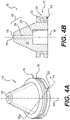
- FIG. 4A is a perspective view of an outlet assembly according to some example embodiments.
- FIG. 4B is a cross-sectional view along line IVB-IVB' of the outlet assembly of FIG. 4A according to some example embodiments.
- FIG. 4C is a perspective view of an outlet assembly according to some example embodiments.
- FIG. 4D is a cross-sectional view along line IVD-IVD' of the outlet assembly of FIG. 4C according to some example embodiments.
- the second bayonet connector assembly 157 may include a radially outward-facing bayonet receptacle connector element that includes a base structure 502 with a circumferential groove 504 extending into the interior of the base structure 502 at least partially around the outer circumference of the base structure 502, and one or more coaxial channels 506 at least partially defined by base structure 502 that extend coaxially from an edge of the base structure 502 into the circumferential groove 504.
- the second bayonet connector assembly 157 includes two separate coaxial channels 506 extending along opposite outer sides of the output assembly 150. Referring to FIGS.
- the first bayonet connector assembly 117 may include a radially inward facing bayonet plug connector element that includes a base structure 602 that extends around outer surface 119 to at least partially define partial enclosure 217 and one or more plug structures 604 that extend radially inward towards longitudinal axis 650 from the base structure 602.
- the first bayonet connector assembly 117 includes two separate plug structures 604 extending radially inward towards longitudinal axis 650 from opposite inner sides of the base structure 602.
- the first bayonet connector assembly 117 as shown in FIGS. 4C-4D may be complementary to the second bayonet connector assembly 157 as shown in FIGS. 4A-4B , such that the bayonet receptacle connector element of the second bayonet connector assembly 157 is configured to engage with one or more plug structures 604 of the first bayonet connector assembly 117, based on at least the second bayonet connector assembly 157 being inserted into the partial enclosure 217, such that the one or more plug structures 604 are configured to be inserted into the circumferential groove 504 via the one or more coaxial channels 506, and the first and second bayonet connector assemblies 117, 157 are rotated around longitudinal axis 650 in relation to each other, to secure the one or more plug structures 604 within the circumferential groove 504 based on inducing mis-alignment of the one or more plug structures 604 with the one or more coaxial channels 506, thereby establishing the bayonet interface connection between the reservoir 112 and
- FIG. 5A is a perspective view of an outlet assembly according to some example embodiments.
- FIG. 5B is a cross-sectional view along line VB-VB' of the outlet assembly of FIG. 5A according to some example embodiments.
- FIG. 5C is a perspective view of a reservoir assembly according to some example embodiments.
- FIG. 5D is a cross-sectional view along line VD-VD' of the reservoir assembly of FIG. 5C according to some example embodiments.
- the second bayonet connector assembly 157 may include a radially outward facing bayonet plug connector element that includes one or more plug structures 512 that extend radially outward from a base structure 510 in relation to the longitudinal axis 550. As shown in FIGS. 5A-5B , for example, the second bayonet connector assembly 157 may include two plug structures 512 that extend radially outward from opposite outer sides of the base structure 510.
- the first bayonet connector assembly 117 may include a radially inward-facing bayonet receptacle connector element that includes a base structure 602 extending around the outer surface 119 to at least partially define partial enclosure 217, a circumferential groove 612 extending into the interior of the base structure 602 to face radially inward to longitudinal axis 650 at least partially around the inner circumference of the base structure 602, and one or more coaxial channels 614 that extend coaxially in relation to longitudinal axis 650 into the circumferential groove 612 from an edge of the base structure 602. As shown in FIGS.
- the first bayonet connector assembly 117 may include two coaxial channels 614 extending along opposite inner sides of the base structure 602. Referring to FIGS. 5A-5D the first bayonet connector assembly 117 as shown in FIGS. 5C-5D may be complementary to the second bayonet connector assembly 157 as shown in FIGS.
- the bayonet receptacle connector element of the first bayonet connector assembly 117 (for example, circumferential groove 612 and one or more coaxial channels 614) is configured to engage with the bayonet plug connector element (for example, one or more plug structures 512) of the second bayonet connector assembly 157, based on at least the second bayonet connector assembly 157 being inserted into the partial enclosure 217, such that the one or more plug structures 512 are configured to be inserted into the circumferential groove 612 via the one or more coaxial channels 614, and the first and second bayonet connector assemblies 117, 157 are rotated around longitudinal axis 650 in relation to each other, to secure the plug structure 512 within the circumferential groove 612 based on inducing mis-alignment of the one or more plug structures 512 with one or more coaxial channels 614, thereby establishing the bayonet interface connection between the reservoir 112 and the outlet assembly 150.
- the bayonet plug connector element for example, one or more plug structures 512
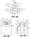
- FIG. 6A is a cross-sectional view of an outlet assembly according to some example embodiments.
- FIG. 6B is a perspective view of a reservoir assembly according to some example embodiments.
- FIG. 6C is a cross-sectional view along line VIC-VIC' of the reservoir assembly of FIG. 6B according to some example embodiments.
- FIG. 7A is a cross-sectional view of an outlet assembly according to some example embodiments.
- FIG. 7B is a perspective view of a reservoir assembly according to some example embodiments.
- FIG. 7C is a cross-sectional view along line VIIC-VIIC' of the reservoir assembly of FIG. 7B according to some example embodiments.
- the second bayonet connector assembly 157 may include a bayonet plug connector element (for example, one or more plug structures 512 as shown in FIG. 6A ) or a bayonet receptacle connector element (for example, circumferential groove 504 and one or more coaxial channels 506 as shown in FIG. 7A ) within an interior of the outlet assembly 150 and at least partially defining a first portion 254 of a conduit 154 extending through the interior of the outlet assembly 150 and which is configured to receive at least a first end 140a of conduit 140 therein when the outlet assembly 150 is detachably coupled with reservoir 112.
- a bayonet plug connector element for example, one or more plug structures 512 as shown in FIG. 6A
- a bayonet receptacle connector element for example, circumferential groove 504 and one or more coaxial channels 506 as shown in FIG. 7A
- the first bayonet connector assembly 117 may extend around the first end 140a of the conduit 140 and include a radially-outward facing bayonet receptacle connector element (for example, circumferential groove 612 and one or more coaxial channels 614 as shown in FIGS. 6B-6C ) or a radially outward facing bayonet plug connector element (for example, one or more plug structures 604 as shown in FIGS. 7B-7C ).
- the second bayonet connector assembly 157 shown in FIG. 6A may be complementary with the first bayonet connector assembly 117 shown in FIGS. 6B-6C
- the second bayonet connector assembly 157 shown in FIG. 7A may be complementary with the first bayonet connector assembly 117 shown in FIGS. 7B-7C .
- FIG. 8A is a side view of a reservoir and an outlet assembly decoupled from the reservoir according to some example embodiments.
- FIG. 8B is a cross-sectional view along line VIIIB-VIIIB' of the decoupled reservoir and outlet assembly of FIG. 8A according to some example embodiments.
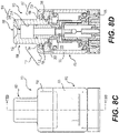
- FIG. 8C is a side view of a reservoir and an outlet assembly coupled with the reservoir according to some example embodiments.
- FIG. 8D is a cross-sectional view along line VIIID-VIIID' of the coupled reservoir and outlet assembly of FIG. 8C according to some example embodiments.
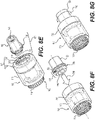
- FIG. 8E is a perspective view of the decoupled reservoir and outlet assembly of FIG. 8A according to some example embodiments.
- FIG. 8F is a perspective view of the decoupled reservoir and outlet assembly of FIG.
- FIG. 8G is a perspective view of a reservoir and an outlet assembly coupled with the reservoir according to some example embodiments.
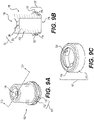
- FIG. 9A is a perspective view of an outlet assembly according to some example embodiments.
- FIG. 9B is a cross-sectional view along line IXB-IXB' of the outlet assembly of FIG. 9A according to some example embodiments.
- FIG. 9C is a perspective view of a bayonet connector assembly according to some example embodiments.
- the first and second bayonet connector assemblies 117, 157 may be similar to the first and second bayonet connector assemblies 117, 157 shown in FIGS. 4A-4D , where the first bayonet connector assembly 117 may include a radially inward facing bayonet plug connector element that includes two plug structures 704 extending radially inward from opposite inner sides of a base structure 702 that extends around a longitudinal axis of the vapor generator assembly 110, and the second bayonet connector assembly 157 may include a radially outward facing bayonet receptacle connector element that includes circumferential groove 706 and two coaxial channels 708 extending along opposite outer sides of the second bayonet connector assembly 157.
- the outlet assembly 150 may include an instance of structural material 152 that defines a cylindrical outer surface of at least a portion of the outlet assembly, and at least a portion of the housing 111 of the vapor generator assembly 110 (for example, at least a portion of the housing 113 of the reservoir 112) may be transparent or translucent to visible light.
- detachably coupling the first and second bayonet connector assemblies 117, 157 of the reservoir 112 and outlet assembly 150, respectively may include inserting 790 at least the second bayonet connector assembly 157 into the partial enclosure 217, such that one or more coaxial channels 708 of the second bayonet connector assembly 157 are aligned with the one or more plug structures 704 of the first bayonet connector assembly 117 and the inserting 790 results in the one or more plug structures 704 being received into circumferential groove 706 via the one or more coaxial channels 708.
- the first bayonet connector assembly 117 includes at least two plug structures 704 extending radially inward from opposite inner sides of a base structure 702, and the second bayonet connector assembly 157 includes at least two coaxial channels 708 extending along opposite outer sides of the second bayonet connector assembly to the circumferential groove 706, but example embodiments are not limited thereto.
- the first bayonet connector assembly 117 may include only one plug structure 704, or the second bayonet connector assembly 157 may include only one coaxial channel 708, or the first bayonet connector assembly 117 may include only one plug structure 704 and the second bayonet connector assembly 157 may include only one coaxial channel 708.
- first bayonet connector assembly 117 may include two or more plug structures 704, or the second bayonet connector assembly 157 may include two or more coaxial channels 708, or the first bayonet connector assembly 117 may include two or more plug structures 704 and the second bayonet connector assembly 157 may include two or more coaxial channels 708.
- the detachably coupling of the first and second bayonet connector assemblies 117, 157 may further include rotating 792 the outlet assembly 150 in relation to the reservoir 112 around the longitudinal axis of the vapor generator assembly 110, so that the one or more plug structures 704 of the first bayonet connector assembly 117 move through circumferential groove 706 to become mis-aligned with the one or more coaxial channels 708 to complete the bayonet interface connection between the reservoir 112 and the outlet assembly 150.
- the first bayonet connector assembly 117 may include a base structure 702 that forms an upper lip structure that extends around a top edge of the one or more inner sides of the base structure 702, and the one or more plug structures 704 may extend from the one or more inner sides of the base structure 702 and beyond the one or more edges of the upper lip structure.
- the one or more plug structures 704 may extend through a separate structure that is located within the one or more spaces bounded by the one or more inner sides of the base structure 702 and the upper lip structure of the base structure 702.
- Detaching the outlet assembly 150 from the reservoir 112 may include performing the reverse of the above process, where the outlet assembly 150 is rotated 792 in relation to the reservoir 112 to cause the one or more plug structures 704 to move through circumferential groove 706 to be aligned with the one or more coaxial channels 708 and then removing the outlet assembly 150 from the partial enclosure 217 such that the plug structure 704 moves through the aligned coaxial channel 708 to disengage from the second bayonet connector assembly 157 via the coaxial channel 708.
- the rotation 792 shown in FIG. 8G is not limited to the direction shown in FIG. 8G .
- the rotation 792 could be clockwise, counter-clockwise, or both clockwise and counter-clockwise.
- the rotation 792 to detachably couple the outlet assembly 150 to the reservoir 112 is in the same direction as the rotation 792 to detach the outlet assembly 150 from the reservoir 112.
- the rotation 792 to detachably couple the outlet assembly 150 to the reservoir 112 is in an opposite direction as the rotation 792 to detach the outlet assembly 150 from the reservoir 112.
- At least one of the first bayonet connector assembly 117 and the second bayonet connector assembly 157 may be configured to generate an audible signal (for example, a "click" sound) based on interaction between elements of the first and second bayonet connector assemblies 117, 157 as a result of the bayonet interface connection between the reservoir 112 and the outlet assembly 150 being established or terminated via coupling or decoupling of the first and second bayonet connector assemblies 117, 157, respectively.
- an audible signal for example, a "click" sound
- At least one of the first bayonet connector assembly 117 and the second bayonet connector assembly 157 may include a structure that is configured to arrest rotation 792 to detachably couple the outlet assembly 150 the reservoir 112, in order to prevent re-alignment of the one or more coaxial channels 708 of the second bayonet connector assembly 157 with the one or more plug structures 704 of the first bayonet connector assembly 117, thereby preventing inadvertent detachment of the outlet assembly 150 from the reservoir 112 when attempting to detachably couple the outlet assembly 150 to the reservoir 112.
- such a structure may be absent from both the first and second bayonet connector assemblies 117, 157, such that the rotation 792 of the rotation of the outlet assembly 150 when the one or more plug structures 704 are received into the circumferential groove 706 is unrestricted.
Landscapes
- Health & Medical Sciences (AREA)
- Engineering & Computer Science (AREA)
- Life Sciences & Earth Sciences (AREA)
- Animal Behavior & Ethology (AREA)
- Anesthesiology (AREA)
- Biomedical Technology (AREA)
- Heart & Thoracic Surgery (AREA)
- Hematology (AREA)
- Bioinformatics & Cheminformatics (AREA)
- Pulmonology (AREA)
- General Health & Medical Sciences (AREA)
- Public Health (AREA)
- Veterinary Medicine (AREA)
- Chemical Vapour Deposition (AREA)
- Fuel Cell (AREA)
- Thermotherapy And Cooling Therapy Devices (AREA)
- Air-Conditioning For Vehicles (AREA)
Description
- Example embodiments relate to electronic vaping devices, e-vaping devices, or the like, and components thereof.
- E-vaping devices, also referred to herein as electronic vaping devices (EVDs) may be used by adult vapers for fluid portable vaping. An e-vaping device may include a reservoir that holds pre-vapor formulation and a vaporizer assembly that may heat pre-vapor formulation drawn from the reservoir to generate a vapor.
- Some e-vaping devices are configured to enable replenishment of the pre-vapor formulation held in a reservoir of the e-vaping device (that is, refilling of the reservoir).
-
US 2017/071251 A1 describes a smoking device comprising a liquid evaporator comprising a liquid reservoir, a wick and a liquid-heating device. The device also comprises a tobacco heater comprising a chamber for receiving tobacco and a chamber-heating device for heating the tobacco in the chamber. A tobacco-flow channel carries vapor from the tobacco in the chamber through the liquid reservoir to the wick where it combines with liquid vapor, the combined vapor then being discharged via a liquid flow-channel through an intake-opening arrangement, which is the part of the device from which the user takes in the vapor from the device. In other words, the intake-opening arrangement may also be referred to as the outlet of the device. - The device of
US 2017/071251 A1 has a modular arrangement, with the liquid evaporator forming part of a liquid-evaporator module and the tobacco heater forming part of a tobacco-heater module. The liquid-evaporator module comprises an evaporator-connecting arrangement for connecting to a heater-connecting arrangement of the tobacco-heater module using a bayonet connection. - In an alternative arrangement, the liquid-evaporator module and the tobacco-heater module comprise bayonet connections at both ends, so that the positions of the liquid evaporator module and the tobacco-heater module may be swapped.
US 2017/071251 A1 describes a mouthpiece module that may be attached to either the liquid-evaporator module or the tobacco-heater module via the bayonet connection. - According to the present disclosure there is provided a reservoir assembly for an e-vaping device, the reservoir assembly according to claim 1.
- The conduit may extend from a vaporizer assembly.
- The vaporizer assembly may be in fluid communication with the exterior of the reservoir assembly through the interior of the outlet assembly when the bayonet interface connection is established.
- The conduit may extend through the space defined by the first bayonet connector assembly.
- The first bayonet connector assembly may include a bayonet plug connector element and may be configured to detachably couple with a complementary bayonet receptacle connector element of the second bayonet connector assembly to establish the bayonet interface connection.
- The reservoir assembly may further include a vaporizer connector assembly configured to detachably couple the reservoir with the vaporizer assembly.
- An end of the conduit may be coupled to the vaporizer connector assembly, such that the conduit is configured to couple with the vaporizer assembly via the vaporizer connector assembly.
- The first bayonet connector assembly may be directly coupled to the end of the reservoir.
- According to the present disclosure there is provided a vapor generator assembly for an e-vaping device, the vapor generator assembly according to claim 7.
- The vaporizer assembly may be in fluid communication with the exterior of the vapor generator assembly through the interior of the outlet assembly when the bayonet interface connection is established.
- The conduit may extend through the space defined by the first bayonet connector assembly.
- The first bayonet connector assembly may include a bayonet plug connector and may be configured to detachably couple with a bayonet receptacle connector of the second bayonet connector assembly to establish the bayonet interface connection.
- The vapor generator assembly may include a vaporizer connector assembly, wherein the reservoir is detachably coupled with the vaporizer assembly through the vaporizer connector assembly.
- An end of the conduit may be coupled to the vaporizer connector assembly, such that the conduit is coupled with the vaporizer assembly via the vaporizer connector assembly.
- The first bayonet connector assembly may be directly coupled to the end of the reservoir.
- According to the present disclosure there is provided an e-vaping device according to claim 13.
- The vaporizer assembly may be in fluid communication with the exterior of the vapor generator assembly through the interior of the outlet assembly when the bayonet interface connection is established.
- The conduit may extend through the space defined by the first bayonet connector assembly.
- The first bayonet connector assembly may include a bayonet plug connector and may be configured to detachably couple with a bayonet receptacle connector of the second bayonet connector assembly to establish the bayonet interface connection.
- The first bayonet connector assembly may be directly coupled to the end of the reservoir. The power supply assembly may include a rechargeable battery.
- The power supply assembly may be detachably coupled with the vapor generator assembly.
- The e-vaping device may include a vaporizer connector assembly. The reservoir may be detachably coupled with the vaporizer assembly through the vaporizer connector assembly.
- An end of the conduit may be coupled to a vaporizer connector assembly, such that the conduit is coupled with the vaporizer assembly via the vaporizer connector assembly.
- The various features and advantages of the non-limiting example embodiments herein may become more apparent upon review of the detailed description in conjunction with the accompanying drawings. The accompanying drawings are merely provided for illustrative purposes and should not be interpreted to limit the scope of the claims. The accompanying drawings are not to be considered as drawn to scale unless explicitly noted. For purposes of clarity, various dimensions of the drawings may have been exaggerated.
-
FIG. 1A is a perspective view of an e-vaping device according to some example embodiments. -
FIG. 1B is a perspective view of an e-vaping device according to some example embodiments. -
FIG. 1C is a cross-sectional view along line IC-IC' of the e-vaping device ofFIG. 1A according to some example embodiments. -
FIG. 1D is a cross-sectional view along line ID-ID' of the e-vaping device ofFIG. 1B according to some example embodiments. -
FIG. 2A is a cross-sectional view of a portion of a vapor generator assembly that includes a reservoir coupled with an outlet assembly according to some example embodiments. -
FIG. 2B is a cross-sectional view of a portion of a vapor generator assembly that includes a reservoir decoupled from an outlet assembly according to some example embodiments. -
FIG. 3A is a cross-sectional view of a portion of a vapor generator assembly that includes a reservoir coupled with an outlet assembly according to some example embodiments. -
FIG. 3B is a cross-sectional view of a portion of a vapor generator assembly that includes a reservoir decoupled from an outlet assembly according to some example embodiments. -
FIG. 4A is a perspective view of an outlet assembly according to some example embodiments. -
FIG. 4B is a cross-sectional view along line IVB-IVB' of the outlet assembly ofFIG. 4A according to some example embodiments. -
FIG. 4C is a perspective view of a reservoir assembly according to some example embodiments. -
FIG. 4D is a cross-sectional view along line IVD-IVD' of the reservoir assembly ofFIG. 4C according to some example embodiments. -
FIG. 5A is a perspective view of an outlet assembly according to some example embodiments. -
FIG. 5B is a cross-sectional view along line VB-VB' of the outlet assembly ofFIG. 5A according to some example embodiments. -
FIG. 5C is a perspective view of a reservoir assembly according to some example embodiments. -
FIG. 5D is a cross-sectional view along line VD-VD' of the reservoir assembly ofFIG. 5C according to some example embodiments. -
FIG. 6A is a cross-sectional view of an outlet assembly according to some example embodiments. -
FIG. 6B is a perspective view of a reservoir assembly according to some example embodiments. -
FIG. 6C is a cross-sectional view along line VIC-VIC' of the reservoir assembly ofFIG. 6B according to some example embodiments. -
FIG. 7A is a cross-sectional view of an outlet assembly according to some example embodiments. -
FIG. 7B is a perspective view of a reservoir assembly according to some example embodiments. -
FIG. 7C is a cross-sectional view along line VIIC-VIIC' of the reservoir assembly ofFIG. 7B according to some example embodiments. -
FIG. 8A is a side view of a reservoir and an outlet assembly decoupled from the reservoir according to some example embodiments. -
FIG. 8B is a cross-sectional view along line VIIIB-VIIIB' of the decoupled reservoir and outlet assembly ofFIG. 8A according to some example embodiments. -
FIG. 8C is a side view of a reservoir and an outlet assembly coupled with the reservoir according to some example embodiments. -
FIG. 8D is a cross-sectional view along line VIIID-VIIID' of the coupled reservoir and outlet assembly ofFIG. 8C according to some example embodiments. -
FIG. 8E is a perspective view of the decoupled reservoir and outlet assembly ofFIG. 8A according to some example embodiments. -
FIG. 8F is a perspective view of the decoupled reservoir and outlet assembly ofFIG. 8E according to some example embodiments. -
FIG. 8G is a perspective view of a reservoir and an outlet assembly coupled with the reservoir according to some example embodiments. -
FIG. 9A is a perspective view of an outlet assembly according to some example embodiments. -
FIG. 9B is a cross-sectional view along line IXB-IXB' of the outlet assembly ofFIG. 9A according to some example embodiments. -
FIG. 9C is a perspective view of a bayonet connector assembly according to some example embodiments. - Some detailed example embodiments are disclosed herein. However, specific structural and functional details disclosed herein are merely provided for purposes of describing example embodiments. Example embodiments may, however, be embodied in many alternate forms and should not be construed as limited to only the example embodiments set forth herein.
- Accordingly, while example embodiments are capable of various modifications and alternative forms, example embodiments thereof are shown by way of example in the drawings and will herein be described in detail. It should be understood, however, that there is no intent to limit example embodiments to the particular forms disclosed, but to the contrary, example embodiments are to cover all modifications, equivalents, and alternatives thereof. Like numbers refer to like elements throughout the description of the figures.
- It should be understood that when an element or layer is referred to as being "on," "connected to," "coupled to," "attached to," "adjacent to," or "covering" another element or layer, it may be directly on, connected to, coupled to, attached to, adjacent to or covering the other element or layer or intervening elements or layers may be present. In contrast, when an element is referred to as being "directly on," "directly connected to," or "directly coupled to" another element or layer, there are no intervening elements or layers present. Like numbers refer to like elements throughout the specification.
- It should be understood that, although the terms first, second, third, and so forth may be used herein to describe various elements, components, regions, layers or sections, these elements, components, regions, layers, or sections should not be limited by these terms. These terms are only used to distinguish one element, component, region, layer, or section from another region, layer, or section. Therefore, a first element, component, region, layer, or section discussed below could be termed a second element, component, region, layer, or section without departing from the teachings of example embodiments.
- Spatially relative terms (for example, "beneath," "below," "lower," "above," "upper," and the like) may be used herein for ease of description to describe one element or feature's relationship to another element or feature as illustrated in the figures. It should be understood that the spatially relative terms are intended to encompass different orientations of the device in use or operation in addition to the orientation depicted in the figures. For example, if the device in the figures is turned over, elements described as "below" or "beneath" other elements or features would then be oriented "above" the other elements or features. Therefore, the term "below" may encompass both an orientation of above and below. The device may be otherwise oriented (rotated 90 degrees or at other orientations) and the spatially relative descriptors used herein interpreted accordingly.
- The terminology used herein is for the purpose of describing various example embodiments only and is not intended to be limiting of example embodiments. As used herein, the singular forms "a," "an," and "the" are intended to include the plural forms as well, unless the context clearly indicates otherwise. It will be further understood that the terms "includes," "including," "comprises," and "comprising," when used in this specification, specify the presence of stated features, integers, steps, operations, elements, or components, and so forth, but do not preclude the presence or addition of one or more other features, integers, steps, operations, elements, components, and so forth, or groups thereof.
- When the words "about" and "substantially" are used in this specification in connection with a numerical value, it is intended that the associated numerical value include a tolerance of ±10 percent around the stated numerical value, unless otherwise explicitly defined.
- Example embodiments are described herein with reference to cross-sectional illustrations that are schematic illustrations of example embodiments. As such, variations from the shapes of the illustrations are to be expected. Therefore, example embodiments should not be construed as limited to the shapes of regions illustrated herein but are to include deviations in shapes.
- Vapor, aerosol and dispersion are used interchangeably and are meant to cover the matter generated or outputted by the devices disclosed, claimed and equivalents thereof.
- Unless otherwise defined, all terms (including technical and scientific terms) used herein have the same meaning as commonly understood by one of ordinary skill in the art to which example embodiments belong. It will be further understood that terms, including those defined in commonly used dictionaries, should be interpreted as having a meaning that is consistent with their meaning in the context of the relevant art and will not be interpreted in an idealized or overly formal sense unless expressly so defined herein.
- Hardware may be implemented using processing or control circuitry such as, but not limited to, one or more processors, one or more Central Processing Units (CPUs), one or more microcontrollers, one or more arithmetic logic units (ALUs), one or more digital signal processors (DSPs), one or more microcomputers, one or more field programmable gate arrays (FPGAs), one or more System-on-Chips (SoCs), one or more programmable logic units (PLUs), one or more microprocessors, one or more Application Specific Integrated Circuits (ASICs), or any other device or devices capable of responding to and executing instructions in a defined manner.
-
FIG. 1A is a perspective view of ane-vaping device 100 according to some example embodiments.FIG. 1B is a perspective view of ane-vaping device 100 according to some example embodiments.FIG. 1C is a cross-sectional view along line IC-IC' of thee-vaping device 100 ofFIG. 1A according to some example embodiments.FIG. 1D is a cross-sectional view along line ID-ID' of thee-vaping device 100 ofFIG. 1B according to some example embodiments. As used herein, the term "e-vaping device" is inclusive of all types of electronic vaping devices, regardless of form, size or shape. - Referring to
FIGS. 1A-1D , thee-vaping device 100 includes avapor generator assembly 110 andpower supply assembly 120. In some example embodiments, avapor generator assembly 110 that is configured to be detachably coupled to apower supply assembly 120 to form ane-vaping device 100 may be referred to herein as a cartridge. - In some example embodiments, the
vapor generator assembly 110 andpower supply assembly 120 include respectivecomplementary connector assemblies connector assemblies connector assemblies connector assembly - As shown in
FIGS. 1A-1D , thevapor generator assembly 110 may include anouter housing 111, and thepower supply assembly 120 may include anouter housing 121, where theouter housing 111 and theouter housing 121 may collectively define an outer housing 191 of thee-vaping device 100. - As shown in
FIGS. 1A-1D , thevapor generator assembly 110 may include areservoir 112, avaporizer assembly 130, a firstbayonet connector assembly 117 and anoutlet assembly 150, where theoutlet assembly 150 includes a secondbayonet connector assembly 157. Structures of a first and secondbayonet connector assemblies FIGS. 2A-2B ,3A-3B ,4A-4D ,5A-5D ,6A-6C ,7A-7C ,8A-8G , and9A-9C . - As shown in
FIGS. 1A-1D , areservoir 112, firstbayonet connector assembly 117, andvaporizer connector assembly 148 may be included in areservoir assembly 102 of some example embodiments. - As shown in
FIGS. 1A-1D , theouter housing 111 of thevapor generator assembly 110 may include anouter housing 113 of thereservoir 112 and anouter housing 131 of thevaporizer assembly 130, whereouter housings outer housing 111. In some example embodiments,housings example embodiments housings outer housing 113 of thereservoir 112 may at least partially define aninterior space 115. Thereservoir 112 may be configured to hold a pre-vapor formulation within the interior of thereservoir 112, where the interior may include theinterior space 115 at least partially defined by theouter housing 113 of thereservoir 112. - As shown in at least
FIGS. 1C-1D , thereservoir 112 may include afluid port 114 which extends through theouter housing 113 of thereservoir 112 between theinterior space 115 of thereservoir 112 and an exterior of at least thereservoir 112, such that thefluid port 114 is in fluid communication with the exterior of at least thereservoir 112 and thereby may enable fluid communication between thereservoir 112 and the exterior of at least thereservoir 112. - In some example embodiments, the
vaporizer assembly 130 andreservoir 112 include respectivecomplementary connector assemblies connector assemblies vaporizer connector assembly 148 may be configured to detachably couple thereservoir 112 with thevaporizer assembly 130, for example based on detachably coupling with theconnector assembly 138 of thevaporizer assembly 130. In some example embodiments, theconnector assemblies connector assembly - As shown in at least
FIGS. 1C-1D , thevaporizer assembly 130 may include anouter housing 131 that at least partially defines aninterior space 135 of thevaporizer assembly 130. As further shown in at leastFIGS. 1C-1D , thevaporizer assembly 130 may include afluid port 134 which extends through theouter housing 131 of thevaporizer assembly 130 between theinterior space 135 of thevaporizer assembly 130 and an exterior of thevaporizer assembly 130, such that thefluid port 134 may enable fluid communication between theinterior space 135 and an exterior of thevaporizer assembly 130. As further shown inFIG. 1B , thefluid port 134 may enable fluid communication between thereservoir 112 and thevaporizer assembly 130. In some example embodiments, thefluid port 134 extends through theouter housing 113 of thereservoir 112, in addition to or instead of extending through theouter housing 131 of thevaporizer assembly 130. In some example embodiments, wherehousing 113 meets withhousing 131 may form part of the same housing, or these may be two separate housings that can be connected together (for example, viacomplementary connector assemblies 138, 148). In some example embodiments,fluid port 114 may include more than one port (for example, there may be multiple first fluid ports), thefluid port 134 may include more than one port (for example, there may be multiple second fluid ports), or thefluid port 114 and thefluid port 134 may each include more than one port. - The
vaporizer assembly 130 may include aheater 136 and a dispensinginterface 137. The dispensinginterface 137 may be in fluid communication with thefluid port 134 and in fluid communication with thereservoir 112 through at least thefluid port 134, andpre-vapor formulation 174 drawn into theinterior space 135 throughfluid port 134 may be drawn by the dispensinginterface 137 to be in fluid communication with theheater 136. The heater 136 (also referred to herein as a heating element) may heat pre-vapor formulation drawn from thereservoir 112 by the dispensing interface (for example, through the fluid port 134) to generate a vapor. - As further shown in
FIGS. 1A-1D , thevapor generator assembly 110 may include aninlet port 132 that extends through theouter housing 131 of thevaporizer assembly 130 and is configured to direct air from an exterior of the vapor generator assembly 110 (for example, an ambient environment) to flow into thevaporizer assembly 130, to flow in fluid communication with theheater 136 within at least a portion of theinterior space 135 of thevaporizer assembly 130. As further shown inFIGS. 1A-1D , thevaporizer assembly 130 may include anoutlet port 142 extending through theouter housing 131 of thevaporizer assembly 130 and thevapor generator assembly 110 may further include aconduit 140coupling outlet ports vaporizer assembly 130 and the exterior of the vapor generator assembly 110 (for example, the ambient environment). - In operation of the
e-vaping device 100,air 162 may be drawn into thevaporizer assembly 130 through at least theinlet port 132, vapor generated by theheater 136 may be entrained in the air that is drawn into thevaporizer assembly 130, and a mixture of the air and entrained vapor (simply referred to herein as generated vapor 164) may be drawn from thevaporizer assembly 130 to the exterior of thevapor generator assembly 110 throughoutlet port 142,conduit 140, andoutlet port 144. As shown inFIGS. 1A-1D , theoutlet port 142 may extend through theouter housing 131 of thevaporizer assembly 130, theouter housing 113 of thereservoir 112, avaporizer connector assembly 148, aconnector assembly 138, a sub-combination thereof, or a combination thereof. - In some example embodiments,
reservoir assembly 102 is configured to enable refilling of the pre-vapor formulation held inreservoir 112. As shown inFIGS. 1C-1D , thefluid port 114 may enable direct fluid communication between thereservoir 112 and an exterior of at least thereservoir 112. Therefore, thereservoir assembly 102 may be configured to enable refilling of thereservoir 112 via introduction ofpre-vapor formulation 172 into thereservoir 112 through at least thefluid port 114. - Still referring to
FIGS. 1A-1D , thereservoir assembly 102 may include a firstbayonet connector assembly 117 that is coupled to afirst end 119a of thereservoir 112. The firstbayonet connector assembly 117 may include a bayonet plug connector element (also referred to as a male bayonet connector element), a bayonet receptacle connector element (also referred to as a female bayonet connector element), or both a bayonet plug connector element and a bayonet receptacle connector element. Additionally, as shown inFIGS. 1C-1D , thefluid port 114 may extend through theouter housing 113 of thereservoir 112 to anouter surface 119 of theouter housing 113 at thefirst end 119a of thereservoir 112. - As further shown in
FIGS. 1C-1D , theconduit 140 may include afirst end 140a and asecond end 140b that extend to opposite first andsecond ends reservoir 112, where thefirst end 140a of theconduit 140 extends into the firstbayonet connector assembly 117 and thesecond end 140b of theconduit 140 is coupled with the vaporizer assembly 130 (either directly or indirectly via at least a vaporizer connector assembly 148). Accordingly, theconduit 140 may establish fluid communication between thevaporizer assembly 130 and the exterior of thevapor generator assembly 110 through the firstbayonet connector assembly 117. As shown, thefirst end 140a of theconduit 140 may include an opening that is defined as theoutlet port 144, and thesecond end 140b of theconduit 140 may include an opening that is in fluid communication withoutlet port 142. In some example embodiments, the firstbayonet connector assembly 117 is directly coupled to thefirst end 140a of theconduit 140. In some example embodiments, where thevapor generator assembly 110 includes thevaporizer connector assembly 148 and theconnector assembly 138, thesecond end 140b of theconduit 140 may be coupled to thevaporizer connector assembly 148, such that thesecond end 140b of theconduit 140 is configured to couple with thevaporizer assembly 130 through thevaporizer connector assembly 148. - Still referring to
FIGS. 1A-1D , thevapor generator assembly 110 may include an outlet assembly 150 (also referred to herein as a mouthpiece, mouthpiece assembly, or the like) that is configured to be detachably coupled 182 to thereservoir 112 via a bayonet interface connection between thereservoir 112 and theoutlet assembly 150. As shown, theoutlet assembly 150 may include an instance ofstructural material 152, aconduit 154 extending through the interior of the outlet assembly 150 (for example, through the instance ofstructural material 152 such that one or more inner surfaces of the instance ofstructural material 152 may at least partially define the conduit 154) betweenopposite openings bayonet connector assembly 157. The secondbayonet connector assembly 157 may include a bayonet plug connector element (also referred to as a male bayonet connector element), a bayonet receptacle connector element (also referred to as a female bayonet connector), or both a bayonet plug connector element and a bayonet receptacle connector element. As shown inFIGS. 1A-7A , in some example embodiments thestructural material 152 of theoutlet assembly 150 may define a conical shape, but example embodiments are not limited thereto. For example, as shown inFIGS. 8A-9C , theoutlet assembly 150 may include an instance of structural material that defines an outer surface having a cylindrical shape. - As shown in
FIGS. 1A-1D , the first and secondbayonet connector assemblies reservoir 112 and theoutlet assembly 150, such that theconduit 140 is in fluid communication with an exterior of at least thereservoir 112 through an interior of the outlet assembly (for example, through conduit 154), and thefluid port 114 is isolated from an exterior of at least thereservoir 112 by at least a portion of theoutlet assembly 150 to isolate thereservoir 112 from fluid communication with the exterior of at least the reservoir 112 (independently of at least the vaporizer assembly 130). In some example embodiments, thefluid port 114 is configured to be isolated from the exterior of at least thereservoir 112 by at least a portion of thestructural material 152 of theoutlet assembly 150, at least a portion of the secondbayonet connector assembly 157 of theoutlet assembly 150, or a combination thereof, based on theoutlet assembly 150 being detachably coupled with thereservoir 112 via the bayonet interface connection established via the coupling of the first and secondbayonet connector assemblies - Based on the
outlet assembly 150 isolating thefluid port 114 based on being detachably coupled with thereservoir 112 via the detachable coupling of the first and secondbayonet connector assemblies pre-vapor formulation 172 between thereservoir 112 and an exterior of at least thereservoir 112 independently of passing through thevaporizer assembly 130 may be at least partially mitigated. To enable refilling of thepre-vapor formulation 172 in thereservoir 112 via thefluid port 114, theoutlet assembly 150 may be detached from the reservoir 112 (via decoupling of the first and secondbayonet connector assemblies 117, 157) to expose thefluid port 114 to an exterior of at least thereservoir 112. - In some example embodiments, the first and second
bayonet connector assemblies bayonet connector assembly 117 may include a bayonet plug connector element and the secondbayonet connector assembly 157 may include a bayonet receptacle connector element that is complementary to the bayonet plug connector element of the firstbayonet connector assembly 117, such that at least the first and secondbayonet connector assemblies bayonet connector assembly 117 is configured to detachably couple with the secondbayonet connector assembly 157 to establish the bayonet interface connection between thereservoir 112 and theoutlet assembly 150 based on the detachably coupling of the complementary bayonet connector elements of the first and secondbayonet connector assemblies - In some example embodiments, the
vapor generator assembly 110 is configured to provide improved resistance against transfer ofpre-vapor formulation 172 from thereservoir 112 to an exterior of at least thereservoir 112 through thefluid port 114 based on theoutlet assembly 150 being detachably coupled to at least thereservoir 112 via a bayonet interface connection established by the firstbayonet connector assembly 117 coupling with the secondbayonet connector assembly 157. In certain example embodiments, the bayonet interface connection may provide improved isolation of thefluid port 114 from the exterior of at least thereservoir 112 in relation to other interface connections, including, without limitation, a threaded interface connection. - Still referring to
FIGS 1A-1D , apower supply assembly 120 according to some example embodiments may include apower supply 122. Thepower supply 122 may be a rechargeable battery, and thepower supply assembly 120 may be configured to supply electrical power from thepower supply 122 to the vapor generator assembly 110 (for example, to theheater 136 via one or more electrical leads) to support vapor generation at thevaporizer assembly 130. - As shown in
FIGS. 1C-1D , ane-vaping device 100 according to some example embodiments may include an instance ofcontrol circuitry 124 that may be configured to control the supply of electrical power from thepower supply 122 to the vapor generator assembly 110 (for example, to the vaporizer assembly 130). In the example embodiments shown inFIGS. 1C-1D , thecontrol circuitry 124 is included in thepower supply assembly 120, but it will be understood that, in some example embodiments, thecontrol circuitry 124 may be included in thevapor generator assembly 110 instead of thepower supply assembly 120. - In some example embodiments, wherein the
vapor generator assembly 110 and thepower supply assembly 120 are configured to be detachably coupled viacomplementary connector assemblies vapor generator assembly 110 and thepower supply assembly 120 may be established based onconnector assemblies heater 136, thecontrol circuitry 124, and thepower supply 122. The electrical circuit may include one or more electrical leads in one or both ofconnector assemblies - In some example embodiments, the
e-vaping device 100 may be a unitary piece that includes thevapor generator assembly 110 and thepower supply assembly 120 in the unitary piece, instead of including thevapor generator assembly 110 and thepower supply assembly 120 as separate pieces that are coupled together to form thee-vaping device 100. - In some example embodiments, the
power supply 122 may include a battery. In some examples, thepower supply 122 may be a Lithium-ion battery or one of its variants, for example a Lithium-ion polymer battery, a nickel-metal hydride battery, a nickel cadmium battery, a lithium-manganese battery, a lithium-cobalt battery, a fuel cell, and so forth, a sub-combination thereof, or a combination thereof. Thee-vaping device 100 may be usable by an adult vaper until the energy in thepower supply 122 is depleted or a minimum voltage cut-off level is achieved. Further, thepower supply 122 may be rechargeable and may include circuitry configured to allow the battery to be chargeable by an external charging device. To recharge thee-vaping device 100, a Universal Serial Bus (USB) charger or other suitable charger assembly may be used. - In some example embodiments, the
power supply 122 may be electrically connected with theheater 136 bycontrol circuitry 124 based on a signal received at thecontrol circuitry 124 from a sensor of thee-vaping device 100, an interface of thee-vaping device 100, or a combination thereof. To control the supply of electrical power to aheater 136, thecontrol circuitry 124 may execute one or more instances of computer-executable program code. Thecontrol circuitry 124 may include a processor and a memory. The memory may be a computer-readable storage medium storing computer-executable code. Thecontrol circuitry 124 may be a special purpose machine configured to execute the computer-executable code to control the supply of electrical power to theheater 136. - In some example embodiments,
connector assemblies e-vaping device 100, such that thevapor generator assembly 110 and thepower supply assembly 120 are fixedly coupled together (for example, are integral to each other) and are precluded from being detachably coupled with each other, and the outer housing 191 of thee-vaping device 100 may include theouter housing 111 of thevapor generator assembly 110 and theouter housing 121 of thepower supply assembly 120 as a unitary piece of material. - In some example embodiments,
connector assemblies vapor generator assembly 110, such that thereservoir 112 and thevaporizer assembly 130 are fixedly coupled together (for example, are integral to each other) and are precluded from being detachably coupled with each other, and theouter housing 111 of thevapor generator assembly 110 may include theouter housing 113 of thereservoir 112 and theouter housing 131 of the vaporizer assembly as a unitary piece of material. - The exterior of at least the
reservoir 112 may include an exterior of thereservoir 112, an exterior of thereservoir assembly 102, an exterior of thevapor generator assembly 110, an exterior of thee-vaping device 100, a sub-combination thereof, or a combination thereof. Accordingly, an exterior of at least thereservoir 112 may include an external environment that is external to thereservoir 112, an external environment that is external to thereservoir assembly 102, an external environment that is external to thevaporizer assembly 130, an external environment that is external to thevapor generator assembly 110, an external environment that is external to thee-vaping device 100, a sub-combination thereof, or a combination thereof. - The pre-vapor formulation is a material or combination of materials that may be transformed into a vapor. In some example embodiments, one or more portions of the
vapor generator assembly 110 may be replaceable. Such one or more portions may include thevaporizer assembly 130, thereservoir 112, thereservoir assembly 102, thepower supply assembly 120, theoutlet assembly 150, a sub-combination thereof, or a combination thereof. In some example embodiments, the entiree-vaping device 100 may be disposed once thereservoir 112, thevaporizer assembly 130, or a combination thereof is depleted. -
FIG. 2A is a cross-sectional view of a portion of avapor generator assembly 110 that includes areservoir 112 coupled with anoutlet assembly 150 according to some example embodiments.FIG. 2B is a cross-sectional view of a portion of avapor generator assembly 110 that includes areservoir 112 decoupled from anoutlet assembly 150 according to some example embodiments.FIG. 3A is a cross-sectional view of a portion of avapor generator assembly 110 that includes areservoir 112 coupled with anoutlet assembly 150 according to some example embodiments.FIG. 3B is a cross-sectional view of a portion of avapor generator assembly 110 that includes areservoir 112 decoupled from anoutlet assembly 150 according to some example embodiments. - In some example embodiments, including the example embodiments shown in
FIGS. 2A-2B , the firstbayonet connector assembly 117 may extend around an outer circumference of anouter surface 119 of theouter housing 113 of thereservoir 112, at thefirst end 119a of thereservoir 112, such that the firstbayonet connector assembly 117 includes one or more bayonet connector elements that face radially inward toward thelongitudinal axis 250, and firstbayonet connector assembly 117 and theouter surface 119 at least partially define apartial enclosure 217, and the secondbayonet connector assembly 157 may extend around anouter surface 152s of thestructural material 152 of theoutlet assembly 150, such that the secondbayonet connector assembly 157 includes one or more bayonet connector elements that face radially outward from thelongitudinal axis 250. Examples of firstbayonet connector assemblies 117 and secondbayonet connector assemblies 157 according to example embodiments are further described below. As shown inFIGS. 2A-2B , when first and secondbayonet connector assemblies reservoir 112 and theoutlet assembly 150, the one or more radially-outward facing bayonet connector elements of the secondbayonet connector assembly 157 may engage with the one or more complementary and radially-inward facing bayonet connector elements of the firstbayonet connector assembly 117, and at least a portion of the secondbayonet connector assembly 157 and thestructural material 152 of theoutlet assembly 150 may occupy thepartial enclosure 217. - As shown in
FIGS. 2A-2B , thefluid port 114 may extend through theouter housing 113 of thereservoir 112 to theouter surface 119, such that thefluid port 114 may be in direct fluid communication with thepartial enclosure 217 when theoutlet assembly 150 is decoupled from thereservoir 112. Still referring toFIGS. 2A-2B , at least thefirst end 140a of theconduit 140 may extend out of thereservoir 112 and at least partially through thepartial enclosure 217 that is at least partially defined by the firstbayonet connector assembly 117 and theouter surface 119. As shown inFIGS. 2A-2B , theoutlet assembly 150conduit 154 may include afirst portion 254, defined by inner surfaces of thestructural material 152 of theoutlet assembly 150, that has a first diameter and a first length that substantially corresponds (for example, corresponds within manufacturing tolerances and material tolerances) to a diameter and length of thefirst end 140a of theconduit 140. Accordingly, as shown inFIGS. 2A-2B , theoutlet assembly 150 may enclose thefirst end 140a of theconduit 140 that extends out of thereservoir 112 and at least partially through thepartial enclosure 217 within thefirst portion 254 of theconduit 154, based on theoutlet assembly 150 being detachably coupled to thereservoir 112. As further shown inFIGS. 2A-2B , theconduit 154 may include asecond portion 256 in addition to thefirst portion 254, where thefirst portion 254 and thesecond portion 256 have different diameters, different lengths, or different diameters and different lengths. - In certain example embodiments, such an enclosure of the
first end 140a of theconduit 140 may establish an airtight or substantially airtight seal between theconduit 140 and theoutlet assembly 150. In some example embodiments, theconduit 140 is in fluid communication with the exterior of at least thereservoir assembly 102 through theconduit 154 that extends through the interior of theoutlet assembly 150. Accordingly, when generatedvapor 164 is directed throughconduit 140 from avaporizer assembly 130, the generatedvapor 164 may be directed from theconduit 140 to the exterior of thevapor generator assembly 110 through the interior of the outlet assembly 150 (for example, conduit 154). - Still referring to
FIGS. 2A-2B , thestructural material 152 of theoutlet assembly 150 may define abottom surface 252 of theoutlet assembly 150. Theoutlet assembly 150 may be configured to detachably couple with at least thereservoir 112, based on the first and secondbayonet connector assemblies bayonet connector assembly 157, thestructural material 152 of theoutlet assembly 150, or a combination thereof may occupy thepartial enclosure 217 and thebottom surface 252 may cover thefluid port 114 extending through theouter surface 119 of thereservoir 112, thereby isolating thereservoir 112 from fluid communication with an exterior of thereservoir assembly 102 independently of thevaporizer assembly 130. - In some example embodiments, including the example embodiments shown in
FIGS. 3A-3B , the secondbayonet connector assembly 157 may be at least partially located within the interior of theoutlet assembly 150 and may extend around aninner surface 152i of thestructural material 152 to at least partially define afirst portion 254 of theconduit 154 extending through theoutlet assembly 150, and the firstbayonet connector assembly 117 that is complementary to the secondbayonet connector assembly 157 may extend around an outer surface 140as of thefirst end 140a of theconduit 140, such that the firstbayonet connector assembly 117 includes one or more bayonet connector elements that face radially outward from thelongitudinal axis 250 and such that thefirst end 140a of theconduit 140 extends through the firstbayonet connector assembly 117. Examples of firstbayonet connector assemblies 117 and secondbayonet connector assemblies 157 according to example embodiments are further described below. - In some example embodiments, each bayonet connector assembly of the first and second
bayonet connector assemblies outlet assembly 150 with thereservoir 112 may include detachably coupling multiple bayonet connector sub-assemblies of the firstbayonet connector assembly 117 with separate, respective complementary bayonet connector sub-assemblies of the secondbayonet connector assembly 157 to establish multiple bayonet interface connections between theoutlet assembly 150 and thereservoir 112. In some example embodiments, each bayonet connector assembly of the first and secondbayonet connector assemblies FIGS. 2A-2B andFIGS. 3A-3B . Accordingly, in such example embodiments, the firstbayonet connector assembly 117 may include both a bayonet connector sub-assembly that may extend around an outer circumference of anouter surface 119 of theouter housing 113 of thereservoir 112, at thefirst end 119a of thereservoir 112, similarly to the firstbayonet connector assembly 117 ofFIGS. 2A-2B , and another bayonet connector sub-assembly that extends around an outer surface 140as of thefirst end 140a of theconduit 140, similarly to the firstbayonet connector assembly 117 ofFIGS. 3A-3B . Additionally, in such example embodiments, the secondbayonet connector assembly 157 may include both a bayonet connector sub-assembly that may extend around anouter surface 152s of thestructural material 152 of theoutlet assembly 150, similarly to the secondbayonet connector assembly 157 ofFIGS. 2A-2B , and another bayonet connector sub-assembly that may be at least partially located within the interior of theoutlet assembly 150 and may extend around aninner surface 152i of thestructural material 152 to at least partially define afirst portion 254 of theconduit 154 extending through theoutlet assembly 150, similarly to the secondbayonet connector assembly 157 ofFIGS. 3A-3B . -
FIG. 4A is a perspective view of an outlet assembly according to some example embodiments.FIG. 4B is a cross-sectional view along line IVB-IVB' of the outlet assembly ofFIG. 4A according to some example embodiments.FIG. 4C is a perspective view of an outlet assembly according to some example embodiments.FIG. 4D is a cross-sectional view along line IVD-IVD' of the outlet assembly ofFIG. 4C according to some example embodiments. - Referring to
FIGS. 4A-4B , in some example embodiments, the secondbayonet connector assembly 157 may include a radially outward-facing bayonet receptacle connector element that includes abase structure 502 with acircumferential groove 504 extending into the interior of thebase structure 502 at least partially around the outer circumference of thebase structure 502, and one or morecoaxial channels 506 at least partially defined bybase structure 502 that extend coaxially from an edge of thebase structure 502 into thecircumferential groove 504. InFIGS. 4A-4B , for example, the secondbayonet connector assembly 157 includes two separatecoaxial channels 506 extending along opposite outer sides of theoutput assembly 150. Referring toFIGS. 4C-4D , in some example embodiments, the firstbayonet connector assembly 117 may include a radially inward facing bayonet plug connector element that includes abase structure 602 that extends aroundouter surface 119 to at least partially definepartial enclosure 217 and one ormore plug structures 604 that extend radially inward towardslongitudinal axis 650 from thebase structure 602. InFIGS. 4C-4D , for example, the firstbayonet connector assembly 117 includes twoseparate plug structures 604 extending radially inward towardslongitudinal axis 650 from opposite inner sides of thebase structure 602. - Referring to
FIGS. 4A-4D , the firstbayonet connector assembly 117 as shown inFIGS. 4C-4D may be complementary to the secondbayonet connector assembly 157 as shown inFIGS. 4A-4B , such that the bayonet receptacle connector element of the secondbayonet connector assembly 157 is configured to engage with one ormore plug structures 604 of the firstbayonet connector assembly 117, based on at least the secondbayonet connector assembly 157 being inserted into thepartial enclosure 217, such that the one ormore plug structures 604 are configured to be inserted into thecircumferential groove 504 via the one or morecoaxial channels 506, and the first and secondbayonet connector assemblies longitudinal axis 650 in relation to each other, to secure the one ormore plug structures 604 within thecircumferential groove 504 based on inducing mis-alignment of the one ormore plug structures 604 with the one or morecoaxial channels 506, thereby establishing the bayonet interface connection between thereservoir 112 and theoutlet assembly 150. -
FIG. 5A is a perspective view of an outlet assembly according to some example embodiments.FIG. 5B is a cross-sectional view along line VB-VB' of the outlet assembly ofFIG. 5A according to some example embodiments.FIG. 5C is a perspective view of a reservoir assembly according to some example embodiments.FIG. 5D is a cross-sectional view along line VD-VD' of the reservoir assembly ofFIG. 5C according to some example embodiments. - Referring to
FIGS. 5A-5B , in some example embodiments, the secondbayonet connector assembly 157 may include a radially outward facing bayonet plug connector element that includes one ormore plug structures 512 that extend radially outward from abase structure 510 in relation to thelongitudinal axis 550. As shown inFIGS. 5A-5B , for example, the secondbayonet connector assembly 157 may include twoplug structures 512 that extend radially outward from opposite outer sides of thebase structure 510. - Referring to
FIGS. 5C-5D , in some example embodiments, the firstbayonet connector assembly 117 may include a radially inward-facing bayonet receptacle connector element that includes abase structure 602 extending around theouter surface 119 to at least partially definepartial enclosure 217, acircumferential groove 612 extending into the interior of thebase structure 602 to face radially inward tolongitudinal axis 650 at least partially around the inner circumference of thebase structure 602, and one or morecoaxial channels 614 that extend coaxially in relation tolongitudinal axis 650 into thecircumferential groove 612 from an edge of thebase structure 602. As shown inFIGS. 5C-5D , for example, the firstbayonet connector assembly 117 may include twocoaxial channels 614 extending along opposite inner sides of thebase structure 602. Referring toFIGS. 5A-5D the firstbayonet connector assembly 117 as shown inFIGS. 5C-5D may be complementary to the secondbayonet connector assembly 157 as shown inFIGS. 5A-5B , such that the bayonet receptacle connector element of the first bayonet connector assembly 117 (for example,circumferential groove 612 and one or more coaxial channels 614) is configured to engage with the bayonet plug connector element (for example, one or more plug structures 512) of the secondbayonet connector assembly 157, based on at least the secondbayonet connector assembly 157 being inserted into thepartial enclosure 217, such that the one ormore plug structures 512 are configured to be inserted into thecircumferential groove 612 via the one or morecoaxial channels 614, and the first and secondbayonet connector assemblies longitudinal axis 650 in relation to each other, to secure theplug structure 512 within thecircumferential groove 612 based on inducing mis-alignment of the one ormore plug structures 512 with one or morecoaxial channels 614, thereby establishing the bayonet interface connection between thereservoir 112 and theoutlet assembly 150. -
FIG. 6A is a cross-sectional view of an outlet assembly according to some example embodiments.FIG. 6B is a perspective view of a reservoir assembly according to some example embodiments.FIG. 6C is a cross-sectional view along line VIC-VIC' of the reservoir assembly ofFIG. 6B according to some example embodiments.FIG. 7A is a cross-sectional view of an outlet assembly according to some example embodiments.FIG. 7B is a perspective view of a reservoir assembly according to some example embodiments.FIG. 7C is a cross-sectional view along line VIIC-VIIC' of the reservoir assembly ofFIG. 7B according to some example embodiments. - Referring to
FIGS. 6A and7A , in some example embodiments, the secondbayonet connector assembly 157 may include a bayonet plug connector element (for example, one ormore plug structures 512 as shown inFIG. 6A ) or a bayonet receptacle connector element (for example,circumferential groove 504 and one or morecoaxial channels 506 as shown inFIG. 7A ) within an interior of theoutlet assembly 150 and at least partially defining afirst portion 254 of aconduit 154 extending through the interior of theoutlet assembly 150 and which is configured to receive at least afirst end 140a ofconduit 140 therein when theoutlet assembly 150 is detachably coupled withreservoir 112. Referring now toFIGS. 6B-6C andFIGS. 7B-7C , in some example embodiments, the firstbayonet connector assembly 117 may extend around thefirst end 140a of theconduit 140 and include a radially-outward facing bayonet receptacle connector element (for example,circumferential groove 612 and one or morecoaxial channels 614 as shown inFIGS. 6B-6C ) or a radially outward facing bayonet plug connector element (for example, one ormore plug structures 604 as shown inFIGS. 7B-7C ). The secondbayonet connector assembly 157 shown inFIG. 6A may be complementary with the firstbayonet connector assembly 117 shown inFIGS. 6B-6C , and the secondbayonet connector assembly 157 shown inFIG. 7A may be complementary with the firstbayonet connector assembly 117 shown inFIGS. 7B-7C . -
FIG. 8A is a side view of a reservoir and an outlet assembly decoupled from the reservoir according to some example embodiments.FIG. 8B is a cross-sectional view along line VIIIB-VIIIB' of the decoupled reservoir and outlet assembly ofFIG. 8A according to some example embodiments.FIG. 8C is a side view of a reservoir and an outlet assembly coupled with the reservoir according to some example embodiments.FIG. 8D is a cross-sectional view along line VIIID-VIIID' of the coupled reservoir and outlet assembly ofFIG. 8C according to some example embodiments.FIG. 8E is a perspective view of the decoupled reservoir and outlet assembly ofFIG. 8A according to some example embodiments.FIG. 8F is a perspective view of the decoupled reservoir and outlet assembly ofFIG. 8E according to some example embodiments.FIG. 8G is a perspective view of a reservoir and an outlet assembly coupled with the reservoir according to some example embodiments.FIG. 9A is a perspective view of an outlet assembly according to some example embodiments.FIG. 9B is a cross-sectional view along line IXB-IXB' of the outlet assembly ofFIG. 9A according to some example embodiments.FIG. 9C is a perspective view of a bayonet connector assembly according to some example embodiments. - As shown in
FIGS. 8A-9C , in some example embodiments, the first and secondbayonet connector assemblies bayonet connector assemblies FIGS. 4A-4D , where the firstbayonet connector assembly 117 may include a radially inward facing bayonet plug connector element that includes twoplug structures 704 extending radially inward from opposite inner sides of abase structure 702 that extends around a longitudinal axis of thevapor generator assembly 110, and the secondbayonet connector assembly 157 may include a radially outward facing bayonet receptacle connector element that includescircumferential groove 706 and twocoaxial channels 708 extending along opposite outer sides of the secondbayonet connector assembly 157. As shown inFIGS. 8A-9C , theoutlet assembly 150 may include an instance ofstructural material 152 that defines a cylindrical outer surface of at least a portion of the outlet assembly, and at least a portion of thehousing 111 of the vapor generator assembly 110 (for example, at least a portion of thehousing 113 of the reservoir 112) may be transparent or translucent to visible light. - As shown in at least
FIGS. 8E-8G , detachably coupling the first and secondbayonet connector assemblies reservoir 112 andoutlet assembly 150, respectively, may include inserting 790 at least the secondbayonet connector assembly 157 into thepartial enclosure 217, such that one or morecoaxial channels 708 of the secondbayonet connector assembly 157 are aligned with the one ormore plug structures 704 of the firstbayonet connector assembly 117 and the inserting 790 results in the one ormore plug structures 704 being received intocircumferential groove 706 via the one or morecoaxial channels 708. - As shown in
FIGS. 8A-9C , in some example embodiments the firstbayonet connector assembly 117 includes at least twoplug structures 704 extending radially inward from opposite inner sides of abase structure 702, and the secondbayonet connector assembly 157 includes at least twocoaxial channels 708 extending along opposite outer sides of the second bayonet connector assembly to thecircumferential groove 706, but example embodiments are not limited thereto. For example, in some embodiments, the firstbayonet connector assembly 117 may include only oneplug structure 704, or the secondbayonet connector assembly 157 may include only onecoaxial channel 708, or the firstbayonet connector assembly 117 may include only oneplug structure 704 and the secondbayonet connector assembly 157 may include only onecoaxial channel 708. In another example, the firstbayonet connector assembly 117 may include two ormore plug structures 704, or the secondbayonet connector assembly 157 may include two or morecoaxial channels 708, or the firstbayonet connector assembly 117 may include two ormore plug structures 704 and the secondbayonet connector assembly 157 may include two or morecoaxial channels 708. The detachably coupling of the first and secondbayonet connector assemblies outlet assembly 150 in relation to thereservoir 112 around the longitudinal axis of thevapor generator assembly 110, so that the one ormore plug structures 704 of the firstbayonet connector assembly 117 move throughcircumferential groove 706 to become mis-aligned with the one or morecoaxial channels 708 to complete the bayonet interface connection between thereservoir 112 and theoutlet assembly 150. - As shown in
FIGS. 8A-9C , the firstbayonet connector assembly 117 may include abase structure 702 that forms an upper lip structure that extends around a top edge of the one or more inner sides of thebase structure 702, and the one ormore plug structures 704 may extend from the one or more inner sides of thebase structure 702 and beyond the one or more edges of the upper lip structure. As further shown inFIGS. 8A-8G , the one ormore plug structures 704 may extend through a separate structure that is located within the one or more spaces bounded by the one or more inner sides of thebase structure 702 and the upper lip structure of thebase structure 702. - Detaching the
outlet assembly 150 from thereservoir 112 may include performing the reverse of the above process, where theoutlet assembly 150 is rotated 792 in relation to thereservoir 112 to cause the one ormore plug structures 704 to move throughcircumferential groove 706 to be aligned with the one or morecoaxial channels 708 and then removing theoutlet assembly 150 from thepartial enclosure 217 such that theplug structure 704 moves through the alignedcoaxial channel 708 to disengage from the secondbayonet connector assembly 157 via thecoaxial channel 708. - It will be understood that the
rotation 792 shown inFIG. 8G is not limited to the direction shown inFIG. 8G . For example, therotation 792 could be clockwise, counter-clockwise, or both clockwise and counter-clockwise. In some example embodiments, therotation 792 to detachably couple theoutlet assembly 150 to thereservoir 112 is in the same direction as therotation 792 to detach theoutlet assembly 150 from thereservoir 112. In some example embodiments, therotation 792 to detachably couple theoutlet assembly 150 to thereservoir 112 is in an opposite direction as therotation 792 to detach theoutlet assembly 150 from thereservoir 112. - At least one of the first
bayonet connector assembly 117 and the secondbayonet connector assembly 157 may be configured to generate an audible signal (for example, a "click" sound) based on interaction between elements of the first and secondbayonet connector assemblies reservoir 112 and theoutlet assembly 150 being established or terminated via coupling or decoupling of the first and secondbayonet connector assemblies bayonet connector assembly 117 and the secondbayonet connector assembly 157 may include a structure that is configured to arrestrotation 792 to detachably couple theoutlet assembly 150 thereservoir 112, in order to prevent re-alignment of the one or morecoaxial channels 708 of the secondbayonet connector assembly 157 with the one ormore plug structures 704 of the firstbayonet connector assembly 117, thereby preventing inadvertent detachment of theoutlet assembly 150 from thereservoir 112 when attempting to detachably couple theoutlet assembly 150 to thereservoir 112. In some example embodiments, such a structure may be absent from both the first and secondbayonet connector assemblies rotation 792 of the rotation of theoutlet assembly 150 when the one ormore plug structures 704 are received into thecircumferential groove 706 is unrestricted. - While a number of example embodiments have been disclosed herein, it should be understood that other variations may be possible. Such variations are not to be regarded as a departure from the scope of the present disclosure, and all such modifications as would be obvious to one skilled in the art are intended to be included within the scope of the following claims.
Claims (21)
- A reservoir assembly (102) for an e-vaping device (100), the reservoir assembly (102) comprising:a reservoir (112) configured to hold pre-vapor formulation, wherein the reservoir (112) includes a fluid port (114) extending through an outer housing of the reservoir (112);a first bayonet connector assembly (117) at an end of the reservoir (112); anda conduit (140) extending into a space defined by the first bayonet connector assembly (117),wherein the first bayonet connector assembly (117) is configured to detachably couple with a second bayonet connector assembly (157) of an outlet assembly (150) to establish a bayonet interface connection between the reservoir (112) and the outlet assembly (150), such that the conduit (140) is in fluid communication with an exterior of the reservoir assembly (102) through an interior of the outlet assembly (150); andwherein the fluid port (114) is isolated from the exterior of the reservoir assembly (102) by the outlet assembly (150) when the bayonet interface connection is established.
- The reservoir assembly (102) of claim 1, wherein the conduit (140) extends from a vaporizer assembly (130), optionally wherein the vaporizer assembly (130) is in fluid communication with the exterior of the reservoir assembly (102) through the interior of the outlet assembly (150) when the bayonet interface connection is established.
- The reservoir assembly (102) of claim 2, further comprising:
a vaporizer connector assembly (148) configured to detachably couple the reservoir (112) with the vaporizer assembly (130), optionally wherein an end of the conduit (140) is coupled to the vaporizer connector assembly (148), such that the conduit (140) is configured to couple with the vaporizer assembly (130) via the vaporizer connector assembly (148). - The reservoir assembly (102) of any preceding claim, wherein the conduit (140) extends through the space defined by the first bayonet connector assembly (117).
- The reservoir assembly (102) of any preceding claim, wherein the first bayonet connector assembly (117) includes a bayonet plug connector element and is configured to detachably couple with a complementary bayonet receptacle connector element of the second bayonet connector (157) assembly to establish the bayonet interface connection.
- The reservoir assembly (102) of any preceding claim, wherein the first bayonet connector assembly (117) is directly coupled to the end of the reservoir (112).
- A vapor generator assembly (110) for an e-vaping device (100), the vapor generator assembly (110) comprising:a reservoir (112) and a vaporizer assembly (130), the reservoir (112) configured to supply pre vapor formulation to the vaporizer assembly (130), wherein the reservoir (112) includes a first fluid port (114) extending through an outer housing of the reservoir (112);a first bayonet connector assembly (117) at an end of the reservoir (112); anda conduit (140) extending from the vaporizer assembly (130) into a space defined by the first bayonet connector assembly (117), the conduit (140) configured to enable fluid communication between the vaporizer assembly (130) and an exterior of the vapor generator assembly (110) through the first bayonet connector assembly (117); andan outlet assembly (150) including a second bayonet connector assembly (157), the second bayonet connector assembly (157) detachably coupled to the first bayonet connector assembly (117) to establish a bayonet interface connection between the reservoir (112) and the outlet assembly (150), such that:the conduit (140) is in fluid communication with the exterior of the vapor generator assembly (110) through an interior of the outlet assembly (150); andthe first fluid port (114) is isolated from the exterior of the vapor generator assembly (110) by the outlet assembly (150) when the bayonet interface connection is established.
- The vapor generator assembly (110) of claim 7, wherein the vaporizer assembly (130) is in fluid communication with the exterior of the vapor generator assembly (110) through the interior of the outlet assembly (150) when the bayonet interface connection is established.
- The vapor generator assembly (110) of claim 7 or 8, wherein the conduit (140) extends through the space defined by the first bayonet connector assembly (117).
- The vapor generator assembly (110) of any of claims 7 to 9, wherein the first bayonet connector assembly (117) includes a bayonet plug connector and is configured to detachably couple with a bayonet receptacle connector of the second bayonet connector assembly (157) to establish the bayonet interface connection.
- The vapor generator assembly (110) of any of claims 7 to 10, further comprising:
a vaporizer connector assembly (148), wherein the reservoir (112) is detachably coupled with the vaporizer assembly (130) through the vaporizer connector assembly (148), optionally wherein an end of the conduit (140) is coupled to the vaporizer connector assembly (148), such that the conduit (140) is coupled with the vaporizer assembly (130) via the vaporizer connector assembly (148). - The vapor generator assembly (110) of any of claims 7 to 11, wherein the first bayonet connector assembly (117) is directly coupled to the end of the reservoir (112).
- An e-vaping device (100), comprising:a vapor generator assembly (110), the vapor generator assembly (110) includinga reservoir (112) and a vaporizer assembly (130), the reservoir (112) configured to hold pre-vapor formulation, the vaporizer assembly (130) configured to heat pre-vapor formulation drawn from the reservoir (112), the reservoir (112) including a first fluid port (114) extending through an outer housing of the reservoir (112);a first bayonet connector assembly (117) at an end of the reservoir (112); anda conduit (140) extending from the vaporizer assembly (130) into a space defined by the first bayonet connector assembly (117); andan outlet assembly (150) including a second bayonet connector assembly (157), the second bayonet connector assembly (157) detachably coupled to the first bayonet connector assembly (117) to establish a bayonet interface connection between the reservoir (112) and the outlet assembly (150), such that:the conduit (140) is in fluid communication with an exterior of the vapor generator assembly (110) through an interior of the outlet assembly (150); andthe first fluid port (114) is isolated from the exterior of the vapor generator assembly (110) by the outlet assembly (150) when the bayonet interface connection is established; anda power supply assembly (120) coupled to the vapor generator assembly (110), the power supply assembly (120) including a power supply (122), the power supply assembly (120) configured to supply electrical power from the power supply (122) to the vaporizer assembly (130) of the vapor generator assembly (110).
- The e-vaping device (100) of claim 13, wherein the vaporizer assembly (130) is in fluid communication with the exterior of the vapor generator assembly (110) through the interior of the outlet assembly (150) when the bayonet interface connection is established.
- The e-vaping device (100) of claim 13 or 14, wherein the conduit (140) extends through the space defined by the first bayonet connector assembly (117).
- The e-vaping device (100) of any of claims 13 to 15, wherein the first bayonet connector assembly (117) includes a bayonet plug connector and is configured to detachably couple with a bayonet receptacle connector of the second bayonet connector assembly (157) to establish the bayonet interface connection.
- The e-vaping device (100) of any of claims 13 to 16, wherein the first bayonet connector assembly (117) is directly coupled to the end of the reservoir (112).
- The e-vaping device (100) of any of claims 13 to 17, wherein the power supply assembly (120) includes a rechargeable battery.
- The e-vaping device (100) of any of claims 13 to 18, wherein the power supply assembly (120) is detachably coupled with the vapor generator assembly (110).
- The e-vaping device (100) of any of claims 13 to 19, further comprising:
a vaporizer connector assembly (148), wherein the reservoir (112) is detachably coupled with the vaporizer assembly (130) through the vaporizer connector assembly (148). - The e-vaping device (100) of any of claims 13 to 20, wherein an end of the conduit (140) is coupled to a vaporizer connector assembly (148), such that the conduit (140) is coupled with the vaporizer assembly (130) via the vaporizer connector assembly (148).
Applications Claiming Priority (2)
| Application Number | Priority Date | Filing Date | Title |
|---|---|---|---|
| US16/196,344 US11445759B2 (en) | 2018-11-20 | 2018-11-20 | E-vaping device |
| PCT/EP2019/081972 WO2020104547A1 (en) | 2018-11-20 | 2019-11-20 | E-vaping device and components thereof |
Publications (2)
| Publication Number | Publication Date |
|---|---|
| EP3883629A1 EP3883629A1 (en) | 2021-09-29 |
| EP3883629B1 true EP3883629B1 (en) | 2022-11-09 |
Family
ID=68653468
Family Applications (1)
| Application Number | Title | Priority Date | Filing Date |
|---|---|---|---|
| EP19808570.6A Active EP3883629B1 (en) | 2018-11-20 | 2019-11-20 | E-vaping device and components thereof |
Country Status (6)
| Country | Link |
|---|---|
| US (3) | US11445759B2 (en) |
| EP (1) | EP3883629B1 (en) |
| JP (1) | JP7544699B2 (en) |
| KR (1) | KR102835873B1 (en) |
| CN (1) | CN112969485A (en) |
| WO (1) | WO2020104547A1 (en) |
Cited By (2)
| Publication number | Priority date | Publication date | Assignee | Title |
|---|---|---|---|---|
| US12349727B2 (en) | 2020-02-04 | 2025-07-08 | Juul Labs, Inc. | Aerosol dispensing device with disposable container |
| US12471629B2 (en) | 2020-02-18 | 2025-11-18 | Juul Labs, Inc. | Mouthpiece for vaporizer including positive temperature coefficient of resistivity heater |
Families Citing this family (3)
| Publication number | Priority date | Publication date | Assignee | Title |
|---|---|---|---|---|
| USD1103474S1 (en) | 2016-02-10 | 2025-11-25 | Cloudious9 Inc. | Vaping device |
| USD930897S1 (en) * | 2019-03-22 | 2021-09-14 | Joyetech Europe Holding Gmbh | Electronic cigarette |
| US12572764B2 (en) * | 2022-09-19 | 2026-03-10 | Skyx Ip Holdings I Llc | Apparatus and method for aerosol delivery |
Family Cites Families (137)
| Publication number | Priority date | Publication date | Assignee | Title |
|---|---|---|---|---|
| US8656913B2 (en) | 2007-06-05 | 2014-02-25 | Allied Healthcare Products, Inc. | Ventilator apparatus |
| UA111630C2 (en) | 2011-10-06 | 2016-05-25 | Сіс Рісорсез Лтд. | BURNING SYSTEM |
| AU2012381926B2 (en) | 2012-06-05 | 2015-08-27 | Huizhou Kimree Technology Co., Ltd., Shenzhen Branch | Electronic cigarette and suction rod thereof |
| US9308336B2 (en) | 2012-09-19 | 2016-04-12 | Kyle D. Newton | Refill diverter for electronic cigarette |
| CN103960781A (en) | 2013-09-29 | 2014-08-06 | 深圳市麦克韦尔科技有限公司 | Electronic cigarette |
| US10154691B2 (en) | 2012-11-26 | 2018-12-18 | Nu Mark Innovations Ltd. | Bonding for an electronic cigarette cartridge |
| US9426120B1 (en) | 2012-12-21 | 2016-08-23 | Mobile Iron, Inc. | Location and time based mobile app policies |
| GB2511303A (en) | 2013-02-27 | 2014-09-03 | British American Tobacco Co | Smoking apparatus |
| CN105163609B (en) | 2013-03-26 | 2018-06-12 | 吉瑞高新科技股份有限公司 | Electronic cigarette |
| WO2014169422A1 (en) | 2013-04-15 | 2014-10-23 | 吉瑞高新科技股份有限公司 | Electronic cigarette |
| KR102278193B1 (en) | 2013-05-21 | 2021-07-19 | 필립모리스 프로덕츠 에스.에이. | Electrically heated aerosol delivery system |
| CN111642812A (en) | 2013-06-14 | 2020-09-11 | 尤尔实验室有限公司 | Multiple heating elements with individual vaporizable materials in electronic vaporization devices |
| CN203538369U (en) | 2013-08-26 | 2014-04-16 | 高珍 | Flow adjustable electronic cigarette atomizer |
| CN105722417A (en) * | 2013-09-13 | 2016-06-29 | 尼克达特公司 | Programmable electronic vaporizing apparatus and smoking cessation system |
| CN203505590U (en) | 2013-10-29 | 2014-04-02 | 深圳市康尔科技有限公司 | Atomizer with gas flow regulating function |
| US10039321B2 (en) | 2013-11-12 | 2018-08-07 | Vmr Products Llc | Vaporizer |
| JP6755180B2 (en) | 2014-02-10 | 2020-09-16 | フィリップ・モーリス・プロダクツ・ソシエテ・アノニム | Cartridges for aerosol generation systems with heater assemblies and aerosol generation systems with fluid permeable heater assemblies |
| DE202014001718U1 (en) * | 2014-02-27 | 2015-05-28 | Xeo Holding GmbH | smoking device |
| DE202014001717U1 (en) * | 2014-02-27 | 2015-05-28 | Xeo Holding GmbH | Function module for a smoke device |
| GB201413021D0 (en) | 2014-02-28 | 2014-09-03 | Beyond Twenty Ltd | Beyond 2 |
| CN203748684U (en) | 2014-04-08 | 2014-08-06 | 深圳市康尔科技有限公司 | Air flow adjustable atomizer |
| CN203860455U (en) | 2014-04-21 | 2014-10-08 | 申敏良 | Airflow-adjustable atomizer assembly for electronic cigarette |
| CN203860454U (en) | 2014-04-21 | 2014-10-08 | 申敏良 | Airflow adjusting assembly for atomizer of electronic cigarette |
| US9814264B2 (en) | 2014-04-23 | 2017-11-14 | Vitor Manuel ROCHA DINIS | Personal vaporizer system |
| CN203851819U (en) | 2014-05-22 | 2014-10-01 | 孔磊 | Smoke-amount-adjustable electronic cigarette atomizer |
| US9955726B2 (en) | 2014-05-23 | 2018-05-01 | Rai Strategic Holdings, Inc. | Sealed cartridge for an aerosol delivery device and related assembly method |
| WO2016004576A1 (en) | 2014-07-08 | 2016-01-14 | 深圳市康尔科技有限公司 | Electronic cigarette allowing liquid to be injected from top and heating assembly to be replaced at bottom |
| CN104082863B (en) | 2014-07-08 | 2017-04-26 | 深圳市康尔科技有限公司 | Electronic cigarette allowing liquid to be injected from top and heating assembly to be replaced at bottom |
| CN203986123U (en) | 2014-07-16 | 2014-12-10 | 深圳市艾维普思科技有限公司 | A kind of electronic cigarette that changes airintake direction |
| CN203986125U (en) | 2014-07-17 | 2014-12-10 | 深圳市康尔科技有限公司 | A kind of electronic cigarette |
| US20160262452A1 (en) | 2014-07-17 | 2016-09-15 | Shenzhen Kanger Technology Co., Ltd | Electronic cigarettes having adjustable vaporizer |
| CN105310112B (en) | 2014-07-31 | 2017-12-05 | 深圳市艾维普思科技有限公司 | A kind of electronic hookah structure |
| CN204048044U (en) | 2014-08-26 | 2014-12-31 | 付云峰 | A kind of electronic smoke atomizer gas flow modulation structure |
| CN104207330B (en) | 2014-08-27 | 2017-05-03 | 深圳葆威道科技有限公司 | Return airflow atomizer and electronic cigarette comprising atomizer |
| WO2016037362A1 (en) | 2014-09-12 | 2016-03-17 | 深圳麦克韦尔股份有限公司 | Electronic cigarette and air switch apparatus thereof |
| PL4088595T3 (en) | 2014-09-17 | 2024-04-22 | Fontem Ventures B.V. | Device for storing and vaporizing liquid media |
| CN204104840U (en) | 2014-09-23 | 2015-01-21 | 陈悦强 | A kind of electronic cigarette of adjustable air flow |
| WO2016045058A1 (en) | 2014-09-25 | 2016-03-31 | 惠州市吉瑞科技有限公司 | Atomization assembly and electronic cigarette |
| US20160095357A1 (en) | 2014-10-03 | 2016-04-07 | Douglas A. Burton | Electronic vaping device and components thereof |
| US20170325503A1 (en) * | 2014-10-28 | 2017-11-16 | Huizhou Kimree Technology Co., Ltd. | Electronic cigarette |
| US10219541B2 (en) | 2014-10-29 | 2019-03-05 | Lubby Holdings, LLC | Cartridge cover for personal vaporizer |
| WO2016073726A2 (en) | 2014-11-05 | 2016-05-12 | Altria Client Services Llc. | Reservoir filling system for an electronic vaping device |
| WO2016090426A1 (en) | 2014-12-08 | 2016-06-16 | Kinchington Holdings Pty Ltd | Electronic cigarette |
| CN104432542A (en) | 2014-12-09 | 2015-03-25 | 朱晓春 | Electronic cigarette and atomizer thereof |
| CN204519374U (en) | 2015-04-20 | 2015-08-05 | 朱晓春 | Atomizer and the electronic cigarette of heat generating component is changed bottom the fluid injection of top |
| EP3031339A1 (en) | 2014-12-09 | 2016-06-15 | Xiaochun Zhu | Top refillable electronic cigarettes |
| US20160157522A1 (en) | 2014-12-09 | 2016-06-09 | Xiaochun Zhu | Vaporizer and electronic cigarettes having the vaporizer |
| TWI674071B (en) | 2014-12-15 | 2019-10-11 | 瑞士商菲利浦莫里斯製品股份有限公司 | Aerosol-generating systems and methods for guiding an airflow inside an electrically heated aerosol-generating system |
| AR103016A1 (en) | 2014-12-15 | 2017-04-12 | Philip Morris Products Sa | AEROSOL GENERATOR SYSTEMS AND METHODS FOR DIRECTING AN AIR FLOW TOWARDS AN ELECTRIC HEATED AEROSOL GENERATOR SYSTEM |
| CN104544568B (en) | 2014-12-25 | 2017-12-01 | 东莞市哈维电子科技有限公司 | A kind of electronic smoke atomizer of adjustable resistor and air-flow size |
| GB201501060D0 (en) | 2015-01-22 | 2015-03-11 | Nicoventures Holdings Ltd | Vapour provision system and cartridge therefor |
| CN107105784B (en) | 2015-01-26 | 2021-04-06 | 惠州市吉瑞科技有限公司 | Atomization component and electronic cigarette |
| CN207285189U (en) | 2015-03-06 | 2018-05-01 | 惠州市吉瑞科技有限公司深圳分公司 | Atomization components and electronic cigarettes |
| WO2016145612A1 (en) | 2015-03-17 | 2016-09-22 | 惠州市吉瑞科技有限公司 | Atomizing component and electronic cigarette |
| CN107427070A (en) | 2015-03-17 | 2017-12-01 | 惠州市吉瑞科技有限公司 | A kind of atomizing component and electronic cigarette |
| US20160286860A1 (en) | 2015-03-31 | 2016-10-06 | Richard Reed FLAYLER | Electronic vaporizing device having an automatically re-sealable reservoir tank |
| CN204540839U (en) | 2015-04-01 | 2015-08-12 | 深圳市联君烟博士电子技术有限责任公司 | Protective cover hidden air inlet atomizer for electric |
| WO2016154994A1 (en) | 2015-04-02 | 2016-10-06 | 惠州市吉瑞科技有限公司 | Atomizing component and electronic cigarette |
| US10306929B2 (en) | 2015-04-24 | 2019-06-04 | Shenzhen Smoore Technology Limited | Electronic cigarette and atomizer device thereof |
| WO2016172847A1 (en) | 2015-04-28 | 2016-11-03 | 深圳麦克韦尔股份有限公司 | Inhaler and atomization component thereof |
| CN204994614U (en) * | 2015-05-30 | 2016-01-27 | 深圳市合元科技有限公司 | Atomizer of liquid can be annotated and electron cigarette of this atomizer is used |
| CN207285190U (en) | 2015-06-15 | 2018-05-01 | 惠州市吉瑞科技有限公司深圳分公司 | an electronic cigarette |
| CN205082671U (en) | 2015-06-19 | 2016-03-16 | 卓尔悦(常州)电子科技有限公司 | Atomizer and aerosol generating device thereof |
| EP3305103B1 (en) | 2015-06-26 | 2020-02-26 | Japan Tobacco Inc. | Atomizing unit |
| CN204861175U (en) | 2015-07-14 | 2015-12-16 | 卓尔悦(常州)电子科技有限公司 | Electronic cigarette |
| US11504489B2 (en) * | 2015-07-17 | 2022-11-22 | Rai Strategic Holdings, Inc. | Contained liquid system for refilling aerosol delivery devices |
| US10721965B2 (en) | 2015-07-29 | 2020-07-28 | Altria Client Services Llc | E-vapor device including heater structure with recessed shell layer |
| CN204907937U (en) | 2015-08-26 | 2015-12-30 | 卓尔悦(常州)电子科技有限公司 | Atomizer and aerosol generating device thereof |
| GB2542376A (en) | 2015-09-16 | 2017-03-22 | Nicoventures Holdings Ltd | Aerosol provision system with variable airflow |
| CN105249535B (en) | 2015-09-30 | 2024-03-05 | 深圳市合元科技有限公司 | Filling container and refillable filling system and filling method |
| WO2017063535A1 (en) | 2015-10-13 | 2017-04-20 | 常州聚为智能科技有限公司 | Atomizer and electronic cigarette using the same |
| US11006667B2 (en) | 2015-10-16 | 2021-05-18 | 14Th Round Inc. | Assembly for providing chemicals for smokeless administration, a disposable tank, and a method of using the same |
| CN205322939U (en) | 2015-10-27 | 2016-06-22 | 深圳市杰仕博科技有限公司 | Thermal -insulated suction nozzle |
| US10021910B2 (en) | 2015-11-13 | 2018-07-17 | Altria Client Services Llc | E-vaping section and e-vaping device, and a method of manufacturing thereof |
| CN205196999U (en) | 2015-11-23 | 2016-05-04 | 深圳市合元科技有限公司 | Atomizer and electronic cigarette |
| CN105286091B (en) | 2015-11-25 | 2018-10-30 | 卓尔悦欧洲控股有限公司 | Atomizer and its electronic cigarette |
| WO2017093357A1 (en) | 2015-11-30 | 2017-06-08 | Philip Morris Products S.A. | Non-combustible smoking device and elements thereof |
| CN105411006A (en) | 2015-12-28 | 2016-03-23 | 昂纳自动化技术(深圳)有限公司 | Electronic cigarette with replaceable atomization core |
| CN205358220U (en) | 2016-01-06 | 2016-07-06 | 常州聚为智能科技有限公司 | Nebulizer and electronic cigarette with same |
| KR20180040059A (en) | 2016-01-20 | 2018-04-19 | 시아오춘 주 | Ceramic vaporizer and electronic cigarettes having the ceramic vaporizer |
| CN205390305U (en) | 2016-02-26 | 2016-07-27 | 申敏良 | Electronic cigarette atomizer |
| CN205456070U (en) | 2016-02-26 | 2016-08-17 | 深圳市合元科技有限公司 | Liquid atomizer can be annotated and electron cigarette of this atomizer is used |
| US10455863B2 (en) * | 2016-03-03 | 2019-10-29 | Altria Client Services Llc | Cartridge for electronic vaping device |
| US10368580B2 (en) | 2016-03-08 | 2019-08-06 | Altria Client Services Llc | Combined cartridge for electronic vaping device |
| KR20180120819A (en) | 2016-03-16 | 2018-11-07 | 시아오춘 주 | Temper-proof locking mechanisms and electronic cigarettes having the same |
| CN205624467U (en) | 2016-03-21 | 2016-10-12 | 深圳市合元科技有限公司 | Tobacco tar heating element reaches electron cigarette and atomizer including this tobacco tar heating element |
| US10433581B2 (en) | 2016-03-29 | 2019-10-08 | Altria Client Services Llc | Electronic vaping device and cartridge for electronic vaping device |
| CA3011956A1 (en) | 2016-03-31 | 2017-10-05 | Philip Morris Products S.A. | Aerosol generating system with separate capsule and vaporizing unit |
| US10463076B2 (en) | 2016-04-11 | 2019-11-05 | Altria Client Services Llc | Electronic vaping device |
| CN205695706U (en) | 2016-04-11 | 2016-11-23 | 深圳麦克韦尔股份有限公司 | Electronic cigarette and nebulizer thereof |
| CN205757176U (en) | 2016-04-14 | 2016-12-07 | 深圳市合元科技有限公司 | Nebulizer and electronic cigarette |
| CN105815810A (en) | 2016-04-20 | 2016-08-03 | 云南中烟工业有限责任公司 | Cigarette holder capable of adjusting smoke concentration |
| CN105876868B (en) | 2016-05-06 | 2019-05-03 | 卓尔悦欧洲控股有限公司 | Atomizer and its electronic cigarette |
| CN105768236B (en) | 2016-05-06 | 2019-04-26 | 卓尔悦欧洲控股有限公司 | Atomizer and its electronic cigarette |
| CN205728065U (en) | 2016-05-10 | 2016-11-30 | 深圳市合元科技有限公司 | Component suction nozzle, nebulizer and electronic cigarette |
| CN205947119U (en) * | 2016-06-03 | 2017-02-15 | 湖南中烟工业有限责任公司 | Electronic cigarette atomizer |
| CN205794806U (en) | 2016-06-07 | 2016-12-14 | 深圳市新宜康科技有限公司 | Upper assembling electronic smoke atomizer |
| CN205794807U (en) | 2016-06-08 | 2016-12-14 | 刘团芳 | A kind of top air inlet top regulating QI stream nebulizer |
| US10111468B2 (en) | 2016-06-13 | 2018-10-30 | Db Innovation Inc. | Vaporization device |
| CN206808661U (en) * | 2016-06-22 | 2017-12-29 | 深圳市合元科技有限公司 | Oil storage cup and atomizer for atomizer |
| CN105942581B (en) | 2016-06-24 | 2019-03-29 | 深圳市新宜康科技股份有限公司 | Top-out core electronic cigarette vaporizer and disposable liquid storage bottle |
| US9795169B1 (en) | 2016-07-05 | 2017-10-24 | Xiaochun Zhu | Replaceable vaporizer assembly and electronic cigarette having the same |
| US10111469B2 (en) | 2016-07-05 | 2018-10-30 | Shenzhen Kanger Technology Co., Ltd. | Vaporizers having top air intake and electronic cigarette having the same |
| US10881139B2 (en) | 2016-07-07 | 2021-01-05 | Altria Client Services Llc | Non-combustible vaping element with tobacco insert |
| US9993025B2 (en) | 2016-07-25 | 2018-06-12 | Fontem Holdings 1 B.V. | Refillable electronic cigarette clearomizer |
| CN205865989U (en) | 2016-08-08 | 2017-01-11 | 卓尔悦欧洲控股有限公司 | Atomizer and electron cigarette with adjust feedback component |
| US11660403B2 (en) | 2016-09-22 | 2023-05-30 | Juul Labs, Inc. | Leak-resistant vaporizer device |
| CN107865461B (en) | 2016-09-22 | 2021-03-30 | 卓尔悦欧洲控股有限公司 | Atomizing head, atomizer and electronic cigarette with atomizer |
| US10004265B2 (en) | 2016-10-12 | 2018-06-26 | Altria Client Services Llc | Application of a multi-chamber cartridge |
| CN106418714B (en) | 2016-10-27 | 2019-04-05 | 深圳瀚星翔科技有限公司 | Electronic atomizer |
| CN206380711U (en) | 2016-10-28 | 2017-08-08 | 深圳市金卓恒电子科技有限公司 | Disjunctor machinery electronic cigarette |
| US10015991B1 (en) | 2016-12-29 | 2018-07-10 | Altria Client Services Llc | Hybrid E-vaping cartridge, E-vaping device including a hybrid E-vaping cartridge, and method of making thereof |
| CN206413751U (en) | 2017-01-09 | 2017-08-18 | 深圳市赛诺邦格科技有限公司 | An atomizer and electronic cigarette with detachable adjustment ring |
| CN206453250U (en) | 2017-01-13 | 2017-09-01 | 常州市派腾电子技术服务有限公司 | A kind of atomizer and electronic cigarette |
| US11006670B2 (en) | 2017-01-16 | 2021-05-18 | Shenzhen First Union Technology Co., Ltd. | Atomizer for electronic cigarette |
| CN106666833A (en) | 2017-01-16 | 2017-05-17 | 深圳市合元科技有限公司 | Electric smoke atomizer capable of realizing tobacco tar warehouse closing action |
| CN206534130U (en) | 2017-02-07 | 2017-10-03 | 常州市派腾电子技术服务有限公司 | Battery component and its electronic cigarette |
| CN108567166A (en) | 2017-03-09 | 2018-09-25 | 深圳市康尔科技有限公司 | Electronic cigarette liquid separating mechanism and electronic cigarette with electronic cigarette liquid separating mechanism |
| CN206978739U (en) | 2017-03-17 | 2018-02-09 | 东莞市伯科电子科技有限公司 | A nebulizer with airtight seal and adjustable airflow |
| CN207306063U (en) | 2017-03-17 | 2018-05-04 | 东莞市伯科电子科技有限公司 | A new type of nebulizer |
| CN206866629U (en) | 2017-03-30 | 2018-01-12 | 刘团芳 | A kind of W shapes air passage atomizer |
| CN206808668U (en) | 2017-03-31 | 2017-12-29 | 深圳市合元科技有限公司 | The atomizer and electronic cigarette of adjustable air inflow |
| CN107411173A (en) | 2017-05-12 | 2017-12-01 | 广东思格雷电子科技股份有限公司 | The atomizer of adjustable gear |
| CN206978745U (en) | 2017-05-12 | 2018-02-09 | 广东思格雷电子科技股份有限公司 | adjustable atomizer |
| CN107411176A (en) | 2017-05-14 | 2017-12-01 | 广东思格雷电子科技股份有限公司 | Electronic smoke atomizer |
| CN207167762U (en) | 2017-05-27 | 2018-04-03 | 深圳中晟达科技有限公司 | A kind of electronic cigarette with new regulative mode |
| CN207100510U (en) | 2017-05-27 | 2018-03-16 | 深圳市热火科技有限公司 | A kind of miniature atomising device of electronic cigarette |
| CN207040881U (en) | 2017-06-07 | 2018-02-27 | 深圳市合元科技有限公司 | Electronic cigarette, atomizer and its air-flow regulating part |
| CN107095346A (en) | 2017-07-13 | 2017-08-29 | 陈芬芬 | A kind of air-flow adjustable electron atomizer |
| CN107373758A (en) | 2017-07-14 | 2017-11-24 | 深圳云图蒸汽科技有限公司 | Electronic cigarette and its atomizer |
| CN207306079U (en) | 2017-09-20 | 2018-05-04 | 深圳市新宜康电子技术有限公司 | Electronic cigarette with normal pressure self-suction function |
| CN207252783U (en) | 2017-08-08 | 2018-04-20 | 邹冰 | Regulating the qi flowing in the channels formula atomizer |
| CN207185918U (en) | 2017-08-25 | 2018-04-06 | 卓尔悦欧洲控股有限公司 | Cover assembly, atomizer and electronic cigarette |
| CN207306075U (en) | 2017-09-04 | 2018-05-04 | 东莞市伯科电子科技有限公司 | One kind is with valvular electronic cigarette |
| JP3214915U (en) | 2017-11-30 | 2018-02-15 | スリー・アールシステム株式会社 | Battery for electronic cigarette and battery charger for electronic cigarette |
| CN107981418A (en) | 2018-01-18 | 2018-05-04 | 深圳市华玉科技发展有限公司 | A kind of adjustable Z-type multichannel air inlet electronic smoke atomizer in top |
| US11071326B2 (en) | 2018-11-20 | 2021-07-27 | Altria Client Services Llc | E-vaping device |
-
2018
- 2018-11-20 US US16/196,344 patent/US11445759B2/en active Active
-
2019
- 2019-11-20 EP EP19808570.6A patent/EP3883629B1/en active Active
- 2019-11-20 JP JP2021526362A patent/JP7544699B2/en active Active
- 2019-11-20 WO PCT/EP2019/081972 patent/WO2020104547A1/en not_active Ceased
- 2019-11-20 CN CN201980071035.5A patent/CN112969485A/en active Pending
- 2019-11-20 KR KR1020217017359A patent/KR102835873B1/en active Active
-
2022
- 2022-08-25 US US17/895,422 patent/US12193511B2/en active Active
-
2024
- 2024-12-06 US US18/971,572 patent/US20250089795A1/en active Pending
Cited By (2)
| Publication number | Priority date | Publication date | Assignee | Title |
|---|---|---|---|---|
| US12349727B2 (en) | 2020-02-04 | 2025-07-08 | Juul Labs, Inc. | Aerosol dispensing device with disposable container |
| US12471629B2 (en) | 2020-02-18 | 2025-11-18 | Juul Labs, Inc. | Mouthpiece for vaporizer including positive temperature coefficient of resistivity heater |
Also Published As
| Publication number | Publication date |
|---|---|
| WO2020104547A1 (en) | 2020-05-28 |
| EP3883629A1 (en) | 2021-09-29 |
| US12193511B2 (en) | 2025-01-14 |
| JP7544699B2 (en) | 2024-09-03 |
| BR112021008790A2 (en) | 2021-08-03 |
| JP2022510567A (en) | 2022-01-27 |
| US20220400763A1 (en) | 2022-12-22 |
| US11445759B2 (en) | 2022-09-20 |
| CN112969485A (en) | 2021-06-15 |
| KR20210091742A (en) | 2021-07-22 |
| KR102835873B1 (en) | 2025-07-21 |
| US20250089795A1 (en) | 2025-03-20 |
| US20200154782A1 (en) | 2020-05-21 |
Similar Documents
| Publication | Publication Date | Title |
|---|---|---|
| US12193511B2 (en) | E-vaping device | |
| US11677252B2 (en) | Charger assembly and charging system for an electronic vaping device | |
| US12471634B2 (en) | E-vaping device | |
| US20250057245A1 (en) | Nicotine e-vaping device | |
| RU2798782C2 (en) | Electronic vaping device and its components | |
| BR112021008790B1 (en) | ELECTRONIC VAPORIZATION DEVICE AND ITS COMPONENTS | |
| RU2839647C1 (en) | Nicotine-containing vapor generator, electronic nicotine vaping device and reservoir assembly for electronic nicotine vaping device |
Legal Events
| Date | Code | Title | Description |
|---|---|---|---|
| STAA | Information on the status of an ep patent application or granted ep patent |
Free format text: STATUS: UNKNOWN |
|
| STAA | Information on the status of an ep patent application or granted ep patent |
Free format text: STATUS: THE INTERNATIONAL PUBLICATION HAS BEEN MADE |
|
| PUAI | Public reference made under article 153(3) epc to a published international application that has entered the european phase |
Free format text: ORIGINAL CODE: 0009012 |
|
| STAA | Information on the status of an ep patent application or granted ep patent |
Free format text: STATUS: REQUEST FOR EXAMINATION WAS MADE |
|
| 17P | Request for examination filed |
Effective date: 20210519 |
|
| AK | Designated contracting states |
Kind code of ref document: A1 Designated state(s): AL AT BE BG CH CY CZ DE DK EE ES FI FR GB GR HR HU IE IS IT LI LT LU LV MC MK MT NL NO PL PT RO RS SE SI SK SM TR |
|
| DAV | Request for validation of the european patent (deleted) | ||
| DAX | Request for extension of the european patent (deleted) | ||
| REG | Reference to a national code |
Ref country code: DE Ref legal event code: R079 Ref document number: 602019021812 Country of ref document: DE Free format text: PREVIOUS MAIN CLASS: A61M0015060000 Ipc: A24F0040400000 |
|
| GRAP | Despatch of communication of intention to grant a patent |
Free format text: ORIGINAL CODE: EPIDOSNIGR1 |
|
| STAA | Information on the status of an ep patent application or granted ep patent |
Free format text: STATUS: GRANT OF PATENT IS INTENDED |
|
| INTG | Intention to grant announced |
Effective date: 20220530 |
|
| RIC1 | Information provided on ipc code assigned before grant |
Ipc: A61M 11/04 20060101ALI20220513BHEP Ipc: A61M 15/06 20060101ALI20220513BHEP Ipc: A24F 40/485 20200101ALI20220513BHEP Ipc: A24F 40/40 20200101AFI20220513BHEP |
|
| GRAS | Grant fee paid |
Free format text: ORIGINAL CODE: EPIDOSNIGR3 |
|
| GRAA | (expected) grant |
Free format text: ORIGINAL CODE: 0009210 |
|
| STAA | Information on the status of an ep patent application or granted ep patent |
Free format text: STATUS: THE PATENT HAS BEEN GRANTED |
|
| AK | Designated contracting states |
Kind code of ref document: B1 Designated state(s): AL AT BE BG CH CY CZ DE DK EE ES FI FR GB GR HR HU IE IS IT LI LT LU LV MC MK MT NL NO PL PT RO RS SE SI SK SM TR |
|
| REG | Reference to a national code |
Ref country code: GB Ref legal event code: FG4D |
|
| REG | Reference to a national code |
Ref country code: CH Ref legal event code: EP Ref country code: AT Ref legal event code: REF Ref document number: 1529771 Country of ref document: AT Kind code of ref document: T Effective date: 20221115 |
|
| REG | Reference to a national code |
Ref country code: DE Ref legal event code: R096 Ref document number: 602019021812 Country of ref document: DE |
|
| REG | Reference to a national code |
Ref country code: IE Ref legal event code: FG4D |
|
| REG | Reference to a national code |
Ref country code: NL Ref legal event code: FP |
|
| REG | Reference to a national code |
Ref country code: LT Ref legal event code: MG9D |
|
| REG | Reference to a national code |
Ref country code: AT Ref legal event code: MK05 Ref document number: 1529771 Country of ref document: AT Kind code of ref document: T Effective date: 20221109 |
|
| PG25 | Lapsed in a contracting state [announced via postgrant information from national office to epo] |
Ref country code: SE Free format text: LAPSE BECAUSE OF FAILURE TO SUBMIT A TRANSLATION OF THE DESCRIPTION OR TO PAY THE FEE WITHIN THE PRESCRIBED TIME-LIMIT Effective date: 20221109 Ref country code: PT Free format text: LAPSE BECAUSE OF FAILURE TO SUBMIT A TRANSLATION OF THE DESCRIPTION OR TO PAY THE FEE WITHIN THE PRESCRIBED TIME-LIMIT Effective date: 20230309 Ref country code: NO Free format text: LAPSE BECAUSE OF FAILURE TO SUBMIT A TRANSLATION OF THE DESCRIPTION OR TO PAY THE FEE WITHIN THE PRESCRIBED TIME-LIMIT Effective date: 20230209 Ref country code: LT Free format text: LAPSE BECAUSE OF FAILURE TO SUBMIT A TRANSLATION OF THE DESCRIPTION OR TO PAY THE FEE WITHIN THE PRESCRIBED TIME-LIMIT Effective date: 20221109 Ref country code: FI Free format text: LAPSE BECAUSE OF FAILURE TO SUBMIT A TRANSLATION OF THE DESCRIPTION OR TO PAY THE FEE WITHIN THE PRESCRIBED TIME-LIMIT Effective date: 20221109 Ref country code: ES Free format text: LAPSE BECAUSE OF FAILURE TO SUBMIT A TRANSLATION OF THE DESCRIPTION OR TO PAY THE FEE WITHIN THE PRESCRIBED TIME-LIMIT Effective date: 20221109 Ref country code: AT Free format text: LAPSE BECAUSE OF FAILURE TO SUBMIT A TRANSLATION OF THE DESCRIPTION OR TO PAY THE FEE WITHIN THE PRESCRIBED TIME-LIMIT Effective date: 20221109 |
|
| PG25 | Lapsed in a contracting state [announced via postgrant information from national office to epo] |
Ref country code: RS Free format text: LAPSE BECAUSE OF FAILURE TO SUBMIT A TRANSLATION OF THE DESCRIPTION OR TO PAY THE FEE WITHIN THE PRESCRIBED TIME-LIMIT Effective date: 20221109 Ref country code: PL Free format text: LAPSE BECAUSE OF FAILURE TO SUBMIT A TRANSLATION OF THE DESCRIPTION OR TO PAY THE FEE WITHIN THE PRESCRIBED TIME-LIMIT Effective date: 20221109 Ref country code: LV Free format text: LAPSE BECAUSE OF FAILURE TO SUBMIT A TRANSLATION OF THE DESCRIPTION OR TO PAY THE FEE WITHIN THE PRESCRIBED TIME-LIMIT Effective date: 20221109 Ref country code: IS Free format text: LAPSE BECAUSE OF FAILURE TO SUBMIT A TRANSLATION OF THE DESCRIPTION OR TO PAY THE FEE WITHIN THE PRESCRIBED TIME-LIMIT Effective date: 20230309 Ref country code: HR Free format text: LAPSE BECAUSE OF FAILURE TO SUBMIT A TRANSLATION OF THE DESCRIPTION OR TO PAY THE FEE WITHIN THE PRESCRIBED TIME-LIMIT Effective date: 20221109 Ref country code: GR Free format text: LAPSE BECAUSE OF FAILURE TO SUBMIT A TRANSLATION OF THE DESCRIPTION OR TO PAY THE FEE WITHIN THE PRESCRIBED TIME-LIMIT Effective date: 20230210 |
|
| P01 | Opt-out of the competence of the unified patent court (upc) registered |
Effective date: 20230529 |
|
| REG | Reference to a national code |
Ref country code: BE Ref legal event code: MM Effective date: 20221130 |
|
| PG25 | Lapsed in a contracting state [announced via postgrant information from national office to epo] |
Ref country code: SM Free format text: LAPSE BECAUSE OF FAILURE TO SUBMIT A TRANSLATION OF THE DESCRIPTION OR TO PAY THE FEE WITHIN THE PRESCRIBED TIME-LIMIT Effective date: 20221109 Ref country code: RO Free format text: LAPSE BECAUSE OF FAILURE TO SUBMIT A TRANSLATION OF THE DESCRIPTION OR TO PAY THE FEE WITHIN THE PRESCRIBED TIME-LIMIT Effective date: 20221109 Ref country code: EE Free format text: LAPSE BECAUSE OF FAILURE TO SUBMIT A TRANSLATION OF THE DESCRIPTION OR TO PAY THE FEE WITHIN THE PRESCRIBED TIME-LIMIT Effective date: 20221109 Ref country code: DK Free format text: LAPSE BECAUSE OF FAILURE TO SUBMIT A TRANSLATION OF THE DESCRIPTION OR TO PAY THE FEE WITHIN THE PRESCRIBED TIME-LIMIT Effective date: 20221109 Ref country code: CZ Free format text: LAPSE BECAUSE OF FAILURE TO SUBMIT A TRANSLATION OF THE DESCRIPTION OR TO PAY THE FEE WITHIN THE PRESCRIBED TIME-LIMIT Effective date: 20221109 |
|
| REG | Reference to a national code |
Ref country code: DE Ref legal event code: R097 Ref document number: 602019021812 Country of ref document: DE |
|
| PG25 | Lapsed in a contracting state [announced via postgrant information from national office to epo] |
Ref country code: SK Free format text: LAPSE BECAUSE OF FAILURE TO SUBMIT A TRANSLATION OF THE DESCRIPTION OR TO PAY THE FEE WITHIN THE PRESCRIBED TIME-LIMIT Effective date: 20221109 Ref country code: LU Free format text: LAPSE BECAUSE OF NON-PAYMENT OF DUE FEES Effective date: 20221120 Ref country code: AL Free format text: LAPSE BECAUSE OF FAILURE TO SUBMIT A TRANSLATION OF THE DESCRIPTION OR TO PAY THE FEE WITHIN THE PRESCRIBED TIME-LIMIT Effective date: 20221109 |
|
| PLBE | No opposition filed within time limit |
Free format text: ORIGINAL CODE: 0009261 |
|
| STAA | Information on the status of an ep patent application or granted ep patent |
Free format text: STATUS: NO OPPOSITION FILED WITHIN TIME LIMIT |
|
| 26N | No opposition filed |
Effective date: 20230810 |
|
| PG25 | Lapsed in a contracting state [announced via postgrant information from national office to epo] |
Ref country code: IE Free format text: LAPSE BECAUSE OF NON-PAYMENT OF DUE FEES Effective date: 20221120 |
|
| PG25 | Lapsed in a contracting state [announced via postgrant information from national office to epo] |
Ref country code: SI Free format text: LAPSE BECAUSE OF FAILURE TO SUBMIT A TRANSLATION OF THE DESCRIPTION OR TO PAY THE FEE WITHIN THE PRESCRIBED TIME-LIMIT Effective date: 20221109 Ref country code: BE Free format text: LAPSE BECAUSE OF NON-PAYMENT OF DUE FEES Effective date: 20221130 |
|
| PG25 | Lapsed in a contracting state [announced via postgrant information from national office to epo] |
Ref country code: CY Free format text: LAPSE BECAUSE OF FAILURE TO SUBMIT A TRANSLATION OF THE DESCRIPTION OR TO PAY THE FEE WITHIN THE PRESCRIBED TIME-LIMIT Effective date: 20221109 |
|
| PG25 | Lapsed in a contracting state [announced via postgrant information from national office to epo] |
Ref country code: MK Free format text: LAPSE BECAUSE OF FAILURE TO SUBMIT A TRANSLATION OF THE DESCRIPTION OR TO PAY THE FEE WITHIN THE PRESCRIBED TIME-LIMIT Effective date: 20221109 Ref country code: HU Free format text: LAPSE BECAUSE OF FAILURE TO SUBMIT A TRANSLATION OF THE DESCRIPTION OR TO PAY THE FEE WITHIN THE PRESCRIBED TIME-LIMIT; INVALID AB INITIO Effective date: 20191120 |
|
| PG25 | Lapsed in a contracting state [announced via postgrant information from national office to epo] |
Ref country code: MC Free format text: LAPSE BECAUSE OF FAILURE TO SUBMIT A TRANSLATION OF THE DESCRIPTION OR TO PAY THE FEE WITHIN THE PRESCRIBED TIME-LIMIT Effective date: 20221109 |
|
| PG25 | Lapsed in a contracting state [announced via postgrant information from national office to epo] |
Ref country code: TR Free format text: LAPSE BECAUSE OF FAILURE TO SUBMIT A TRANSLATION OF THE DESCRIPTION OR TO PAY THE FEE WITHIN THE PRESCRIBED TIME-LIMIT Effective date: 20221109 Ref country code: MC Free format text: LAPSE BECAUSE OF FAILURE TO SUBMIT A TRANSLATION OF THE DESCRIPTION OR TO PAY THE FEE WITHIN THE PRESCRIBED TIME-LIMIT Effective date: 20221109 |
|
| PG25 | Lapsed in a contracting state [announced via postgrant information from national office to epo] |
Ref country code: BG Free format text: LAPSE BECAUSE OF FAILURE TO SUBMIT A TRANSLATION OF THE DESCRIPTION OR TO PAY THE FEE WITHIN THE PRESCRIBED TIME-LIMIT Effective date: 20221109 |
|
| PG25 | Lapsed in a contracting state [announced via postgrant information from national office to epo] |
Ref country code: MT Free format text: LAPSE BECAUSE OF FAILURE TO SUBMIT A TRANSLATION OF THE DESCRIPTION OR TO PAY THE FEE WITHIN THE PRESCRIBED TIME-LIMIT Effective date: 20221109 |
|
| REG | Reference to a national code |
Ref country code: CH Ref legal event code: U11 Free format text: ST27 STATUS EVENT CODE: U-0-0-U10-U11 (AS PROVIDED BY THE NATIONAL OFFICE) Effective date: 20251201 |
|
| PGFP | Annual fee paid to national office [announced via postgrant information from national office to epo] |
Ref country code: NL Payment date: 20251119 Year of fee payment: 7 |
|
| PGFP | Annual fee paid to national office [announced via postgrant information from national office to epo] |
Ref country code: DE Payment date: 20251119 Year of fee payment: 7 |
|
| PGFP | Annual fee paid to national office [announced via postgrant information from national office to epo] |
Ref country code: GB Payment date: 20251121 Year of fee payment: 7 |
|
| PGFP | Annual fee paid to national office [announced via postgrant information from national office to epo] |
Ref country code: IT Payment date: 20251119 Year of fee payment: 7 |
|
| PGFP | Annual fee paid to national office [announced via postgrant information from national office to epo] |
Ref country code: FR Payment date: 20251126 Year of fee payment: 7 |
|
| PGFP | Annual fee paid to national office [announced via postgrant information from national office to epo] |
Ref country code: CH Payment date: 20251201 Year of fee payment: 7 |