EP3883479B1 - Biopsy device with manual firing mechanism - Google Patents
Biopsy device with manual firing mechanism Download PDFInfo
- Publication number
- EP3883479B1 EP3883479B1 EP19817544.0A EP19817544A EP3883479B1 EP 3883479 B1 EP3883479 B1 EP 3883479B1 EP 19817544 A EP19817544 A EP 19817544A EP 3883479 B1 EP3883479 B1 EP 3883479B1
- Authority
- EP
- European Patent Office
- Prior art keywords
- needle
- cutter
- biopsy device
- assembly
- catch
- Prior art date
- Legal status (The legal status is an assumption and is not a legal conclusion. Google has not performed a legal analysis and makes no representation as to the accuracy of the status listed.)
- Active
Links
Images







Classifications
-
- A—HUMAN NECESSITIES
- A61—MEDICAL OR VETERINARY SCIENCE; HYGIENE
- A61B—DIAGNOSIS; SURGERY; IDENTIFICATION
- A61B10/00—Instruments for taking body samples for diagnostic purposes; Other methods or instruments for diagnosis, e.g. for vaccination diagnosis, sex determination or ovulation-period determination; Throat striking implements
- A61B10/02—Instruments for taking cell samples or for biopsy
- A61B10/0233—Pointed or sharp biopsy instruments
- A61B10/0266—Pointed or sharp biopsy instruments means for severing sample
- A61B10/0275—Pointed or sharp biopsy instruments means for severing sample with sample notch, e.g. on the side of inner stylet
-
- A—HUMAN NECESSITIES
- A61—MEDICAL OR VETERINARY SCIENCE; HYGIENE
- A61B—DIAGNOSIS; SURGERY; IDENTIFICATION
- A61B10/00—Instruments for taking body samples for diagnostic purposes; Other methods or instruments for diagnosis, e.g. for vaccination diagnosis, sex determination or ovulation-period determination; Throat striking implements
- A61B10/02—Instruments for taking cell samples or for biopsy
- A61B10/0233—Pointed or sharp biopsy instruments
- A61B10/0283—Pointed or sharp biopsy instruments with vacuum aspiration, e.g. caused by retractable plunger or by connected syringe
-
- A—HUMAN NECESSITIES
- A61—MEDICAL OR VETERINARY SCIENCE; HYGIENE
- A61B—DIAGNOSIS; SURGERY; IDENTIFICATION
- A61B10/00—Instruments for taking body samples for diagnostic purposes; Other methods or instruments for diagnosis, e.g. for vaccination diagnosis, sex determination or ovulation-period determination; Throat striking implements
- A61B10/02—Instruments for taking cell samples or for biopsy
- A61B2010/0208—Biopsy devices with actuators, e.g. with triggered spring mechanisms
Definitions
- Biopsy samples have been obtained in a variety of ways in various medical procedures using a variety of devices.
- Biopsy devices may be used under stereotactic guidance, ultrasound guidance, MRI guidance, PEM guidance, BSGI guidance, or otherwise.
- some biopsy devices may be fully operable by a user using a single hand, and with a single insertion, to capture one or more biopsy samples from a patient.
- some biopsy devices may be tethered to a vacuum module and/or control module, such as for communication of fluids (e.g., pressurized air, saline, atmospheric air, vacuum, etc.), for communication of power, and/or for communication of commands and the like.
- Other biopsy devices may be fully or at least partially operable without being tethered or otherwise connected with another device.
- Other biopsy devices may be fully or at least partially operable without being tethered or otherwise connected with another device.
- a manually actuated needle firing mechanism into a biopsy device to fire a needle of the biopsy device directly into a lesion.
- the needle is manually inserted into the patient and then positioned below or adjacent to the lesion for collection of tissue samples from the lesion itself and/or adjacent tissue.
- US2012/0283563 discloses a biopsy system with a needle and cutter for severing a tissue sample, and a tissue sensor to sense a tissue sample.
- US2012/0109007 discloses a biopsy system with a needle and cutter for severing a tissue sample, and a needle rotation assembly.
- US2007/0106176 discloses a biopsy device with a cutting element which has an inner cannula with a tissue receiving aperture and an inner cannula.
- US2006/0155210 discloses a biopsy instrument with improved needle penetration for piercing dense tissue.
- US2015/0126902 discloses a biopsy device with a cutter extending through a lateral aperture of the needle and vacuum & fluid pumps.
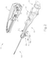
- FIG. 1 shows an exemplary biopsy device (10), comprising a probe (20) and a holster (30).
- Probe (20) comprises a needle assembly (100) that at least partially extends distally from a casing of probe (20). Needle assembly (100) is insertable into a patient's tissue to obtain tissue samples as will be described below.
- Biopsy device (10) further comprises a tissue sample holder (40) into which the tissue samples are deposited.
- probe (20) may be a disposable component and holster (30) may be a reusable component to which probe (20) may be coupled, as is shown in FIG. 2 .
- Use of the term "holster” herein should not be read as requiring any portion of probe (20) to be inserted into any portion of holster (30).
- probe (20) may simply be positioned atop holster (30). Alternatively, a portion of probe (20) may be inserted into holster (30) to secure probe (20) to holster (30). In yet another configuration, a portion of holster (30) may be inserted into probe (20). Further still, probe (20) and holster (30) may be integrally formed as a single unit.
- a port and/or a seal (32) may be provided on holster (30) to couple with a second port and/or a seal (26) on probe (20) such that the vacuum produced by a vacuum pump (50) within holster (30) may be fluidly connected to probe (20).
- Holster (30) may also provide gears (34, 36) which mate to and engage with gears (310, 312) on probe (20).
- vacuum pump (50) can induce a vacuum within needle assembly (100) via tissue sample holder (40) and a tubular cutter (60).
- vacuum pump (50) may be independent of holster (30) and probe (20) and may simply be coupled by vacuum tubes to appropriate ports on biopsy device (10).
- Biopsy device (10) may further be configured in accordance with at least some of the teachings of U.S. Patent No. 8,764,680, entitled “Handheld Biopsy Device with Needle Firing,” issued July 1, 2014 ; and/or U.S. Pub. No. 2012/0065542, entitled “Biopsy Device Tissue Sample Holder with Removable Tray,” published Mar. 15, 2012 .
- Other suitable structural and functional combinations for probe (20) and holster (30) will be apparent to one of ordinary skill in the art in view of the teachings herein.
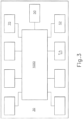
- Holster (30), shown schematically in FIG. 3 comprises vacuum pump (50), a motor (70), a control module (1000), a plurality of buttons (54), a vacuum sensor (52), and any other suitable electrical and/or electromechanical components.
- Vacuum pump (50) of the present example comprises a conventional diaphragm pump that is mechanically coupled to motor (70).
- Vacuum sensor (52) is coupled to vacuum pump (50) or along any vacuum path therefrom such that vacuum sensor (52) can determine the level of vacuum created by vacuum pump (50).
- Vacuum sensor (52) is electrically coupled to control module (1000) so that vacuum sensor (52) may output signals indicative of the vacuum level to control module (1000).
- motor (70) is operable to translate and/or rotate cutter (60) in response to actuation of one or more of buttons (54), as will be described below, and to activate vacuum pump (50), though this is merely optional and a second motor (not shown) may be provided to run vacuum pump (50).
- motor may be coupled to a cutter drive assembly (not shown) and may be activated by control module (1000) upon actuating one or more of buttons (54).
- Such a cutter drive assembly may rotate gears (34, 36) simultaneously.
- gears (34, 36) mesh with gears (310, 312) in probe (20) thus allowing motor (70) to translate and/or rotate cutter (60).
- holster (30) may be provided as will be apparent to one of ordinary skill in the art in view of the teachings herein.
- the cutter drive assembly (not shown) and/or other features of holster (30) may be constructed in accordance with at least some of the teachings of U.S. Patent 8,206,316 entitled “Tetherless Biopsy Device with Reusable Portion,” issued Jun. 26, 2012 ; and/or U.S. Patent No. 8,764,680, entitled “Handheld Biopsy Device with Needle Firing,” issued July 1, 2014 .
- FIG. 4 depicts a partially exploded view of probe (20) showing needle assembly (100), a cutter actuation assembly (300), a probe housing (22, 24) and tissue sample holder (40).
- Needle assembly (100) comprises a needle portion (110) and a valve assembly (200).
- needle assembly (100) is generally operable to pierce tissue where cutter (60) can be positioned to sever a tissue sample from a patient and transport the tissue sample to tissue sample holder (40). More specifically, the needle portion (110) of needle assembly (100) is inserted into a patient's tissue.
- Cutter actuation assembly (300) is then operable to selectively actuate cutter (60) to an open position after pressing one or more of buttons (54).
- cutter (60) Once cutter (60) is actuated by cutter actuation assembly (300) into an open position, tissue may be prolapsed into needle portion (110) by means of a vacuum communicated through cutter (60). Cutter (60) may then be selectively actuated by means of cutter actuation assembly (300) into the closed position, severing the prolapsed tissue from the patient. Vent assembly (300) is then operable to selectively vent a portion of needle portion (110) to atmosphere thus creating a pressure differential between proximal and distal ends of the prolapsed tissue. The pressure differential then transports the prolapsed tissue through cutter (60) to tissue sample holder (40).
- Cutter actuation assembly (300) comprises a series of gears (310, 312).
- Gears (310, 312) are configured to translate and/or rotate cutter (60).
- gears (310, 312) are coupled to motor (70) when probe (20) is attached to holster (30).
- two gears (310, 312) are controlled by motor (70) such that one gear (310) translates cutter (60) and another gear (312) rotates cutter (60) simultaneously.
- Other configurations may be provided utilizing different gear (310) arrangements.
- configurations involving additional motors (70) may be used.
- cutter actuation assembly (300) may be constructed in accordance with at least some of the teachings of U.S. Patent 8,206,316, entitled “Tetherless Biopsy Device with Reusable Portion,” issued Jun. 26, 2012 .
- FIGS. 5 and 6 show an exemplary needle portion (110).
- Needle portion (110) comprises a cannula (120), a partial cannula (130), a tissue piercing tip (140), and a lateral aperture (150).
- cannula (120) is positioned on top of partial cannula (130).
- Cannula (120) and partial cannula (130) define a first lumen portion (160) and a second lumen portion (162).
- cannula (120) is generally circular in shape while partial cannula (130) is semicircular.
- Cannula (120) and partial cannula (130) may be coextensive with their proximal end terminating within the valve assembly (200) and their distal end supporting tissue piercing tip (140).
- needle portion (110) is shown as having a generally ovular cross-section, it should be understood that other cross-sectional shapes may be used. Indeed, needle portion (110) may be comprised of only circular tubes thus creating a generally figure eight cross-section. Alternatively, needle portion (110) may be comprised of two square tubes thus creating a generally square cross-section. Yet in other configurations, needle portion (110) may be comprised of two concentric tubes thus creating a generally circular cross-section. In still other configurations, any other suitable shape may be used.
- FIG. 6 depicts needle portion (110) with cutter (60) disposed therein.
- cannula (120) is configured to receive cutter (60) and to permit cutter (60) to translate and rotate within second lumen portion (162).
- Cannula (120) further comprises lateral aperture (150).
- Lateral aperture (150) is sized to receive prolapsed tissue during operation of biopsy device (10).
- the sidewall of cannula (120) opposite lateral aperture (150) comprises a plurality of openings (170) that provide fluid communication between first lumen portion (160) and second lumen portion (162).
- first lumen portion (160) may selectively provide atmospheric air to vent second lumen portion (162) through the plurality of openings (170).
- Such an atmospheric vent in second lumen portion (162) allows severed tissue to be drawn through cutter (60) and into tissue sample holder (40) under the influence of vacuum from vacuum pump (50).
- cutter (60) can be moved through a variety of positions such as a closed position, an open position and finally in an intermediate position. Each position may correspond to a particular stage in the tissue sample extraction process.
- the cannula (120) may penetrate a patient's tissue when cutter (60) is in a closed position. In the closed position, cutter (60) is in its furthest distal position relative to lateral aperture (150). Thus, cannula (120) may penetrate through tissue smoothly without catching any surrounding tissue that might impede penetration.
- cutter (60) In the open position, cutter (60) is in its furthest proximal position relative to lateral aperture (150).
- This state may, for example, correspond to a position where cannula (120) is oriented inside a patient where a tissue sample may be taken.
- cutter (60) With cutter (60) in its furthest proximal position relative to lateral aperture (150) a vacuum may be applied to prolapse patient's tissue through lateral aperture (150).
- cutter (60) When cutter (60) is in the intermediate position, cutter (60) is in a position between its furthest distal and proximal positions relative to lateral aperture (150).
- cutter (60) may be in a motive state from either a closed position or an open position to a closed or open position, respectively. For example, cutter (60) can move from an open to closed position so that cutter (60) may sever a tissue sample.
- cutter can move from a closed to open position in order to allow the patient's tissue to prolapse through lateral aperture (150).
- these various positions correspond to various pneumatic states of valve assembly (200). It should be understood that the various positions of cutter (60) and the corresponding stages in the tissue extraction process are merely exemplary and other suitable combinations will be apparent to one of ordinary skill in the art from the teachings herein.
- Tissue piercing tip (140) is shown as having a generally conical body with a flat blade protruding therefrom.
- the shape of tissue piercing tip (140) is merely exemplary and many other suitable shapes may be used.
- tissue piercing tip (140) may be in the shape of a blade protruding from needle portion (110), disregarding the conical body.
- the tissue piercing tip (140) may have a flat blade portion of varying shapes and configurations.
- Other various configurations for tissue piercing tip (140) and for needle portion (110) in general may be provided as will be apparent to one of ordinary skill in the art in view of the teachings herein.
- needle portion (110) may be constructed in accordance with at least some of the teachings of U.S. Patent No. 8,801,742, entitled “Needle Assembly and Blade Assembly for Biopsy Device," issued August 8, 2014 .
- FIG. 7 depicts an exploded view of an exemplary valve assembly (200).
- Valve assembly (200) comprises a manifold (210), a static seal (240) and a spool body (250).
- Manifold (210) couples valve assembly (200) to the proximal end of needle portion (110) of needle assembly (100).
- manifold (210) comprises a needle coupling end (220) and a venting end (230).
- needle coupling end (220) of manifold (210) is configured to receive the proximal end of needle portion (110) of needle assembly (100).
- the coupling is made at the termination of cannula (120) and partial cannula (130).
- Cutter (60) then continues through valve assembly (200) to tissue sample holder (40).
- needle coupling end (220) creates an air tight seal around cannula (120) and partial cannula (130) to permit fluid flow from venting end (230) through first lumen portion (160).
- Coupling between needle portion (110) and needle coupling end (220) of manifold (210) may be facilitated by any suitable means such as adhesive bonding, a resilient sealing feature, an interference fitting, or a mechanical fastening means.
- Venting end (230) extends proximally from needle coupling end (220).
- needle coupling end (220) and venting end (230) are integrally formed as a single unit.
- needle coupling end (220) and venting end (230) may be separate components joined together by any suitable fastening means.
- Venting end (230) terminates at the proximal end of manifold (210) where static seal (240) is affixed thereto.
- Venting end (230) defines a plurality of transverse openings (232) that are longitudinally co-located with each other. Transverse openings (232) are equidistantly spaced from each other about the outer perimeter of venting end (230) at their common longitudinal position. As will be described in greater detail below, transverse openings (232) provide communication of atmospheric air to the interior of venting end (230) such that atmospheric air can be fluidly communicated to first lumen portion (160).
- Static seal (240) is affixed to the proximal end of manifold (210). Cutter (60) extends through static seal (240). Although cutter (60) is free to rotate and translate through static seal (240), static seal (240) prevents fluid communication at the interface between cutter (60) and static seal (240). Thus, with the seal created by static seal (240) and the seal created by needle coupling end (220), flow of atmospheric air can be limited to transverse openings (232) to first lumen portion (160).
- Spool body (250) has o-rings (252) situated near the distal end and proximal end of spool body (250). As will be described in more detail below, o-rings (252) create a seal between spool body (250) and the inner diameter surface of venting end (230) of manifold (210). Although spool body (250) is shown with two o-rings (252), any suitable number of o-rings may be utilized. In some examples, spool body (250) can be connected directly to cutter (60) such that spool body (250) can more within manifold (210) as cutter (60) is moved.
- spool body (250) can include one or more vent channels extending therethrough to promote fluid flow through spook body (250).
- spool body (250) may be constructed in accordance with at least some of the teachings of U.S. Pub. No. 2016/0287221, entitled “Biopsy Device with Translating Valve Assembly,” published October 6, 2016 .
- valve assembly (200) can be configured to vent second lumen (162) when cutter (60) is disposed in a distal position. In such a position, spool body (250) is driven distally such that 0-rings (252) are disposed distally of vent openings (232). Atmospheric air can then freely flow through vent openings (252) and spool body (250) into second lumen (162).
- Such a position can correspond to severing of a tissue sample using cutter (60).
- venting is provided to second lumen (162) after a tissue sample has been severed to promote tissue transport through cutter (60).
- tissue may be prolapsed into lateral aperture (150).
- spool body (250) can be positioned by cutter (60) such that 0-rings (252) are positioned on distally and proximally relative to vent openings (232).
- biopsy device (10) of the present example is generally configured for use in biopsy procedures that do not customarily use needle firing for insertion (e.g., ultrasonically guided procedures), in some uses operators may nonetheless prefer to have needle firing in at least some capacity. For instance, some operators may have a preference to quickly fire the needle through a targeted lesion after the needle has been inserted into a patient. Accordingly, in some examples it may be desirable to incorporate various needle firing features into biopsy device (10).
- FIGS. 8 and 9 show an exemplary needle firing assembly (400).
- Needle firing assembly (400) is generally configured to manually cock and fire needle assembly (100) relative to probe housing (22, 24). As will be described in greater detail below, needle firing assembly (400) can be generally used to fire needle assembly (400) directly into a targeted lesion or mass of interest rather than requiring an operator to position needle assembly (100) underneath or around the lesion.
- Needle firing assembly (400) includes a cocking portion (410), a trip or release mechanism (420), and a resilient member or coil spring (450).
- cocking portion (410) includes two laterally extending arms (412) and a catch (414) ( FIG. 9 ).
- cocking portion (410) is generally integrated into the construction of manifold (210) of valve assembly (200). Since manifold (210) is fixedly secured to the proximal end of cannula (120) it should therefore be understood that movement or translation of manifold (210) by cocking portion (410) provides corresponding movement or translation of cannula (120).
- cocking portion (410) of the present example is shown as being integrated into manifold (210), it should be understood that in other examples cocking portion (410) can be configured as an entirely separate component attached to cannula (120) independently of manifold (210).
- Arms (412) extend laterally from manifold (210) and generally protrude from probe housing (22, 24). As will be described in greater detail below, arms (412) are generally configured for grasping by an operator to pull manifold (210) and needle assembly (100) proximally to cock needle firing assembly (400). As such, it should be understood that arms (412) can include various grasping features. For instance, in the present example, arms (412) include a slight curvature to promote gasping. In other examples, arms can include ribs, and/or multiple curvatures to promote gasping. Arms (412) in the present example are also formed of a grid-like structure. Such a structure may prevent slippage by providing for fluid drainage. Of course, such a feature is merely optional and may be omitted in some examples in favor of solid arms (412).
- catch (414) of the present example is defined by an opening in the underside of manifold (210) or by an indentation in the manifold.
- Catch (414) includes a distally facing wall (416).
- wall (416) is generally configured to engage trip mechanism (420) to lock needle firing assembly (400) in a cocked position.
- wall (416) provides a generally flat surface for one or more portions of trip mechanism to latch onto.
- trip mechanism (420) includes a torsion spring (422), an anchor pin (424), and a release arm (430).
- Torsion spring generally fits around anchor pin (424) to bias release arm (430) around the axis of anchor pin (424) upwardly towards catch (414).
- Anchor pin (424) is configured to fasten to at least a portion of probe housing (22, 24) to permit pivoting of release arm (430) about an axis, as will be described in greater detail below.
- Release arm (430) includes a lock tooth (432), a pivot arm (434) and pivot opening (436) disposed between lock tooth (432) and pivot arm (434).
- Lock tooth (432) is generally configured to engage wall (416) of catch (414), as will be described in greater detail below.
- Pivot arm (434) is generally configured to extend from the exterior of probe housing (22, 24) to permit an operator to pivot release arm (430) and thereby release, trigger or trip needle firing assembly (400).
- Pivot opening (436) is configured to receive anchor pin (434) to lock release arm (430) about a pivot axis while still permitting pivoting of release arm (430).
- Coil spring (450) in the present example is used to bias cocking portion (410) towards a distal position.
- coil spring (450) is described herein as a coil spring, it should be understood that in other examples various alternative resilient mechanisms can be used such as a rubber band, an elastic chord or wire, or an elastic rod.
- biopsy device (10) Prior to using needle firing assembly (400), biopsy device (10) can be initialized and prepared for a biopsy procedure. For instance, this process may begin by attaching holster (30) to probe (20). Control module (1000) within holster (30) will then begin an initialization sequence that can include, for example, closing cutter (60) completely, opening cutter (60) completely, then closing cutter (60) fully again.
- an operator may begin cocking needle firing assembly (400) for firing.
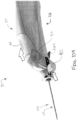
- an operator may first press one or more buttons (54) (as shown with arrow) to retract cutter (60) to the open position.
- biopsy device (10) is prepared for the cocking procedure.
- the operator may then gasp arms (412) of cocking portion (410) and pull arms (412) and cocking portion (410) proximally against the resilient bias of coil spring (450).
- pulling arms (412) proximally results in corresponding proximal movement of needle assembly (100).
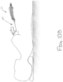
- needle firing assembly (400) Once needle firing assembly (400) is cocked, an operator may insert a portion of needle assembly (100) into the patient as shown in FIG. 10B . Although not shown, it should be understood that prior to this stage the operator may also optionally push one or more buttons (54) to advance cutter (60) to the distal position. Such a use may be desirable to promote penetration of needle assembly (100) through tissue.
- needle assembly (100) may position needle assembly (100) within the patient under image guidance (e.g., ultrasound) to position tissue piercing tip (140) adjacent to a target lesion or mass. Once tissue piercing tip (140) is positioned as desired, an operator may next desire to fire needle assembly (100) to thereby fire tissue piercing tip (140) through the target lesion or mass.
- image guidance e.g., ultrasound
- an operator may pull pivot arm (434) of release arm (430) proximally and upwardly as shown in FIG. 10C . As shown in FIG. 11C , this movement pivots release arm (430) so that lock tooth (432) pivots away from wall (416) of catch (414) and thereby disengages therefrom. Once lock tooth (432) is disengaged from wall (416), the resilient bias of coil spring forces cocking portion (410) distally, which results in distal translation of needle assembly (100).
- tissue collection can be performed through lateral aperture (150) using cutter (60) by pressing one or more buttons (54).
- tissue samples can be collected and deposited in tissue sample holder (40). Once a suitable number of tissue samples have been acquired, needle assembly (100) can be withdrawn from the patient. The tissue samples can then be sent to a pathology laboratory, probe (20) can be disposed of, and holster (30) can be cleaned and/or sterilized for subsequent procedures.
- FIGS. 12A and 12B depict biopsy device (10) equipped with an exemplary alternative needle firing assembly (500).
- Needle firing assembly (500) is substantially similar to needle firing assembly (400) described above, unless otherwise explicitly noted herein. Additionally, it should be understood that needle firing assembly (500) operates substantially similarly as needle firing assembly (400) described above except as otherwise explicitly noted herein.
- needle firing assembly (500) includes a cocking portion (510) that is substantially similar to cocking portion (410) described above.
- needle firing assembly (500) of the present example uses a different trip mechanism (520).
- trip mechanism (520) generally includes a push button release mechanism.
- trip mechanism (520) includes a pivoting lever arm (522) that is pivotable about a pivot pin (524) to engage a lock tooth (526) with cocking portion (510).
- a distal end of lever arm (522) is pivotably fastened to a push button (530).
- Push button (530) includes a flared lower end (532).
- a spring (540) is disposed between probe housing (22, 24) and lower end (532) to resiliently bias push button (530) laterally outwardly or downwardly. This resilient bias causes the distal end of lever arm (522) to also be biased downwardly such that lock tooth (526) is biased upwardly similarly to lock tooth (432) described above.
- needle firing assembly (500) is used substantially similarly to needle firing assembly (400) described above.
- needle firing assembly (500) is cocked by pulling cocking portion (510) proximally. This causes cocking portion (510) to engage cocking portion (510) once pulled proximally to a suitable distance via the resilient bias of lock tooth (526).
- needle firing assembly (500) is fired by way of push button (530) rather than a lever mechanism as shown in FIG. 12B .
- Embodiments of the devices disclosed herein can be designed to be disposed of after a single use, or they can be designed to be used multiple times. Embodiments may, in either or both cases, be reconditioned for reuse after at least one use. Reconditioning may include any combination of the steps of disassembly of the device, followed by cleaning or replacement of particular pieces, and subsequent reassembly. In particular, embodiments of the device may be disassembled, and any number of the particular pieces or parts of the device may be selectively replaced or removed in any combination. Upon cleaning and/or replacement of particular parts, embodiments of the device may be reassembled for subsequent use either at a reconditioning facility, or by a surgical team immediately prior to a surgical procedure.
- reconditioning of a device may utilize a variety of techniques for disassembly, cleaning/replacement, and reassembly. Use of such techniques, and the resulting reconditioned device, are all within the scope of the present application.
- a new or used instrument may be obtained and if necessary cleaned.
- the instrument may then be sterilized.
- the instrument is placed in a closed and sealed container, such as a plastic or TYVEK bag.
- the container and instrument may then be placed in a field of radiation that can penetrate the container, such as gamma radiation, x-rays, or high-energy electrons.
- the radiation may kill bacteria on the instrument and in the container.
- the sterilized instrument may then be stored in the sterile container.
- the sealed container may keep the instrument sterile until it is opened in a medical facility.
- a device may also be sterilized using any other technique known in the art, including but not limited to beta or gamma radiation, ethylene oxide, or steam.
Landscapes
- Health & Medical Sciences (AREA)
- Life Sciences & Earth Sciences (AREA)
- Medical Informatics (AREA)
- Engineering & Computer Science (AREA)
- Biomedical Technology (AREA)
- Heart & Thoracic Surgery (AREA)
- Pathology (AREA)
- Molecular Biology (AREA)
- Surgery (AREA)
- Animal Behavior & Ethology (AREA)
- General Health & Medical Sciences (AREA)
- Public Health (AREA)
- Veterinary Medicine (AREA)
- Surgical Instruments (AREA)
Description
- Biopsy samples have been obtained in a variety of ways in various medical procedures using a variety of devices. Biopsy devices may be used under stereotactic guidance, ultrasound guidance, MRI guidance, PEM guidance, BSGI guidance, or otherwise. For instance, some biopsy devices may be fully operable by a user using a single hand, and with a single insertion, to capture one or more biopsy samples from a patient. In addition, some biopsy devices may be tethered to a vacuum module and/or control module, such as for communication of fluids (e.g., pressurized air, saline, atmospheric air, vacuum, etc.), for communication of power, and/or for communication of commands and the like. Other biopsy devices may be fully or at least partially operable without being tethered or otherwise connected with another device. Other biopsy devices may be fully or at least partially operable without being tethered or otherwise connected with another device.
- Merely exemplary biopsy devices are disclosed in
U.S. Pat. No. 5,526,822, entitled "Method and Apparatus for Automated Biopsy and Collection of Soft Tissue," issued Jun. 18, 1996 ;U.S. Pat. No. 6,086,544, entitled "Control Apparatus for an Automated Surgical Biopsy Device," issued Jul. 11, 2000 ;U.S. Pat. No. 6,626,849, entitled "MRI Compatible Surgical Biopsy Device," issued Sept. 30, 2003 ;U.S. Pat. No. 7,442,171, entitled "Remote Thumbwheel for a Surgical Biopsy Device," issued Oct. 28, 2008 ;U.S. Pat. No. 8,764,680, entitled "Handheld Biopsy Device with Needle Firing," issued Jul. 7, 2014 ;U.S. Pat. No. 9,345,457, entitled "Presentation of Biopsy Sample by Biopsy Device, issued May 24, 2016 U.S. Pub. No. 2006/0074345, entitled "Biopsy Apparatus and Method," published Apr. 6, 2006 , now abandoned;U.S. Pub. No. 2009/0171242, entitled "Clutch and Valving System for Tetherless Biopsy Device," published Jul. 2, 2009 ;U.S. Pub. No. 2010/0152610, entitled "Hand Actuated Tetherless Biopsy Device with Pistol Grip," published Jun. 17, 2010 ; andU.S. Pub. No. 2012/0310110, entitled "Needle Assembly and Blade Assembly for Biopsy Device," published Dec. 6, 2012 . - In some circumstances, it may be desirable to incorporate a manually actuated needle firing mechanism into a biopsy device to fire a needle of the biopsy device directly into a lesion. For instance, in some conventional non-firing biopsy devices, the needle is manually inserted into the patient and then positioned below or adjacent to the lesion for collection of tissue samples from the lesion itself and/or adjacent tissue. In such devices, it may be desirable to still use manual insertion, but to also fire the needle directly into the lesion rather than place it adjacent to the lesion.
- While several systems and methods have been made and used for obtaining a biopsy sample, it is believed that no one prior to the inventors has made or used the invention described in the appended claims.
-
US2012/0283563 discloses a biopsy system with a needle and cutter for severing a tissue sample, and a tissue sensor to sense a tissue sample. -
US2012/0109007 discloses a biopsy system with a needle and cutter for severing a tissue sample, and a needle rotation assembly. -
US2007/0106176 discloses a biopsy device with a cutting element which has an inner cannula with a tissue receiving aperture and an inner cannula. -
US2006/0155210 discloses a biopsy instrument with improved needle penetration for piercing dense tissue. -
US2015/0126902 discloses a biopsy device with a cutter extending through a lateral aperture of the needle and vacuum & fluid pumps. - While the specification concludes with claims which particularly point out and distinctly claim the biopsy device, it is believed the present biopsy device will be better understood from the following description of certain examples taken in conjunction with the accompanying drawings, in which like reference numerals identify the same elements and in which:
-
FIG. 1 depicts a perspective view of an exemplary biopsy device; -
FIG. 2 depicts a perspective view of the biopsy device ofFIG. 1 , showing a holster detached from a probe; -
FIG. 3 depicts a schematic view of exemplary electrical and/or electromechanical components of the holster ofFIG. 2 ; -
FIG. 4 depicts an exploded perspective view of the probe ofFIG. 2 ; -
FIG. 5 depicts a perspective view of an exemplary needle assembly and associated components of the probe ofFIG. 2 ; -
FIG. 6 depicts a cross-sectional perspective view of a distal end of the needle assembly ofFIG. 5 , taken along line 6-6 ofFIG. 5 ; -
FIG. 7 depicts an exploded perspective view of the needle assembly ofFIG. 5 ; -
FIG. 8 depicts an exploded perspective view of an exemplary needle firing assembly associated with the needle assembly ofFIG. 5 ; -
FIG. 9 depicts a detailed perspective view of a cocking portion of the needle firing assembly ofFIG. 8 ; -
FIG. 10A depicts a perspective view of the biopsy device ofFIG. 1 , with the needle firing assembly being moved to a cocked position; -
FIG. 10B depicts a perspective view of the biopsy device ofFIG. 1 being inserted into a patient; -
FIG. 10C depicts a perspective view of the biopsy device ofFIG. 1 , with the needle firing assembly being fired; -
FIG. 10D depicts a perspective view of the biopsy device ofFIG. 1 , with the biopsy device being used to collect a tissue sample; -
FIG. 11A depicts a side cut-away view of the biopsy device ofFIG. 1 , with the needle firing assembly in a pre-cocked position; -
FIG. 11B depicts another side cut-away view of the biopsy device ofFIG. 1 , with the needle firing assembly in the cocked position; -
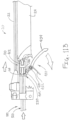
FIG. 11C depict yet another side cut-away view of the biopsy device ofFIG. 1 , with the needle firing assembly being fired; -
FIG. 12A depicts a side elevational view of an exemplary alternative needle firing assembly for use with the biopsy device ofFIG. 1 ; and -
FIG. 12B depicts another side elevational view of the needle firing assembly ofFIG. 12A , with the needle firing assembly in a fired position. -
FIG. 1 shows an exemplary biopsy device (10), comprising a probe (20) and a holster (30). Probe (20) comprises a needle assembly (100) that at least partially extends distally from a casing of probe (20). Needle assembly (100) is insertable into a patient's tissue to obtain tissue samples as will be described below. Biopsy device (10) further comprises a tissue sample holder (40) into which the tissue samples are deposited. By way of example only, probe (20) may be a disposable component and holster (30) may be a reusable component to which probe (20) may be coupled, as is shown inFIG. 2 . Use of the term "holster" herein should not be read as requiring any portion of probe (20) to be inserted into any portion of holster (30). Indeed, in one configuration for biopsy device (10), probe (20) may simply be positioned atop holster (30). Alternatively, a portion of probe (20) may be inserted into holster (30) to secure probe (20) to holster (30). In yet another configuration, a portion of holster (30) may be inserted into probe (20). Further still, probe (20) and holster (30) may be integrally formed as a single unit. - In configurations where probe (20) and holster (30) are separable members, a port and/or a seal (32) may be provided on holster (30) to couple with a second port and/or a seal (26) on probe (20) such that the vacuum produced by a vacuum pump (50) within holster (30) may be fluidly connected to probe (20). Holster (30) may also provide gears (34, 36) which mate to and engage with gears (310, 312) on probe (20). It should be understood that the configuration depicted in
FIG. 2 that communicates vacuum and motive force between holster (30) and probe (20) is merely exemplary. In some versions, such configurations may be constructed in accordance with at least some of the teachings ofU.S. Patent No. 8,206,316 entitled "Tetherless Biopsy Device with Reusable Portion," issued Jun. 26, 2012 ; and/orU.S. Pub. No. 2012/0065542, entitled "Biopsy Device Tissue Sample Holder with Removable Tray," published Mar. 15, 2012 . - With holster (30) and probe (20) connected, vacuum pump (50) can induce a vacuum within needle assembly (100) via tissue sample holder (40) and a tubular cutter (60). However, it should be understood that vacuum may be provided in other ways. For example, vacuum pump (50) may be independent of holster (30) and probe (20) and may simply be coupled by vacuum tubes to appropriate ports on biopsy device (10). Biopsy device (10) may further be configured in accordance with at least some of the teachings of
U.S. Patent No. 8,764,680, entitled "Handheld Biopsy Device with Needle Firing," issued July 1, 2014 ; and/orU.S. Pub. No. 2012/0065542, entitled "Biopsy Device Tissue Sample Holder with Removable Tray," published Mar. 15, 2012 . Other suitable structural and functional combinations for probe (20) and holster (30) will be apparent to one of ordinary skill in the art in view of the teachings herein. - Holster (30), shown schematically in
FIG. 3 , comprises vacuum pump (50), a motor (70), a control module (1000), a plurality of buttons (54), a vacuum sensor (52), and any other suitable electrical and/or electromechanical components. Vacuum pump (50) of the present example comprises a conventional diaphragm pump that is mechanically coupled to motor (70). Vacuum sensor (52) is coupled to vacuum pump (50) or along any vacuum path therefrom such that vacuum sensor (52) can determine the level of vacuum created by vacuum pump (50). Vacuum sensor (52) is electrically coupled to control module (1000) so that vacuum sensor (52) may output signals indicative of the vacuum level to control module (1000). In the configuration shown, motor (70) is operable to translate and/or rotate cutter (60) in response to actuation of one or more of buttons (54), as will be described below, and to activate vacuum pump (50), though this is merely optional and a second motor (not shown) may be provided to run vacuum pump (50). In particular, motor may be coupled to a cutter drive assembly (not shown) and may be activated by control module (1000) upon actuating one or more of buttons (54). Such a cutter drive assembly (not shown) may rotate gears (34, 36) simultaneously. As noted above, gears (34, 36) mesh with gears (310, 312) in probe (20) thus allowing motor (70) to translate and/or rotate cutter (60). Other various configurations for holster (30) may be provided as will be apparent to one of ordinary skill in the art in view of the teachings herein. By way of example only, the cutter drive assembly (not shown) and/or other features of holster (30) may be constructed in accordance with at least some of the teachings ofU.S. Patent 8,206,316 entitled "Tetherless Biopsy Device with Reusable Portion," issued Jun. 26, 2012 ; and/orU.S. Patent No. 8,764,680, entitled "Handheld Biopsy Device with Needle Firing," issued July 1, 2014 . -
FIG. 4 depicts a partially exploded view of probe (20) showing needle assembly (100), a cutter actuation assembly (300), a probe housing (22, 24) and tissue sample holder (40). Needle assembly (100) comprises a needle portion (110) and a valve assembly (200). As will be described in greater detail below, needle assembly (100) is generally operable to pierce tissue where cutter (60) can be positioned to sever a tissue sample from a patient and transport the tissue sample to tissue sample holder (40). More specifically, the needle portion (110) of needle assembly (100) is inserted into a patient's tissue. Cutter actuation assembly (300) is then operable to selectively actuate cutter (60) to an open position after pressing one or more of buttons (54). Once cutter (60) is actuated by cutter actuation assembly (300) into an open position, tissue may be prolapsed into needle portion (110) by means of a vacuum communicated through cutter (60). Cutter (60) may then be selectively actuated by means of cutter actuation assembly (300) into the closed position, severing the prolapsed tissue from the patient. Vent assembly (300) is then operable to selectively vent a portion of needle portion (110) to atmosphere thus creating a pressure differential between proximal and distal ends of the prolapsed tissue. The pressure differential then transports the prolapsed tissue through cutter (60) to tissue sample holder (40). - Cutter actuation assembly (300) comprises a series of gears (310, 312). Gears (310, 312) are configured to translate and/or rotate cutter (60). In the configuration shown, gears (310, 312) are coupled to motor (70) when probe (20) is attached to holster (30). In particular, two gears (310, 312) are controlled by motor (70) such that one gear (310) translates cutter (60) and another gear (312) rotates cutter (60) simultaneously. Other configurations may be provided utilizing different gear (310) arrangements. Moreover, configurations involving additional motors (70) may be used. Various suitable motor (70) and gear (310, 312) combinations will be apparent to one of ordinary skill in the art in view of the teachings herein. Indeed, cutter actuation assembly (300) may be constructed in accordance with at least some of the teachings of
U.S. Patent 8,206,316, entitled "Tetherless Biopsy Device with Reusable Portion," issued Jun. 26, 2012 . -
FIGS. 5 and6 show an exemplary needle portion (110). Needle portion (110) comprises a cannula (120), a partial cannula (130), a tissue piercing tip (140), and a lateral aperture (150). As is shown, cannula (120) is positioned on top of partial cannula (130). Cannula (120) and partial cannula (130) define a first lumen portion (160) and a second lumen portion (162). As is best seen inFIG. 6 , cannula (120) is generally circular in shape while partial cannula (130) is semicircular. Cannula (120) and partial cannula (130) may be coextensive with their proximal end terminating within the valve assembly (200) and their distal end supporting tissue piercing tip (140). Although needle portion (110) is shown as having a generally ovular cross-section, it should be understood that other cross-sectional shapes may be used. Indeed, needle portion (110) may be comprised of only circular tubes thus creating a generally figure eight cross-section. Alternatively, needle portion (110) may be comprised of two square tubes thus creating a generally square cross-section. Yet in other configurations, needle portion (110) may be comprised of two concentric tubes thus creating a generally circular cross-section. In still other configurations, any other suitable shape may be used. -
FIG. 6 depicts needle portion (110) with cutter (60) disposed therein. In particular, cannula (120) is configured to receive cutter (60) and to permit cutter (60) to translate and rotate within second lumen portion (162). Cannula (120) further comprises lateral aperture (150). Lateral aperture (150) is sized to receive prolapsed tissue during operation of biopsy device (10). The sidewall of cannula (120) opposite lateral aperture (150) comprises a plurality of openings (170) that provide fluid communication between first lumen portion (160) and second lumen portion (162). In the present example, first lumen portion (160) may selectively provide atmospheric air to vent second lumen portion (162) through the plurality of openings (170). Such an atmospheric vent in second lumen portion (162) allows severed tissue to be drawn through cutter (60) and into tissue sample holder (40) under the influence of vacuum from vacuum pump (50). - In use, cutter (60) can be moved through a variety of positions such as a closed position, an open position and finally in an intermediate position. Each position may correspond to a particular stage in the tissue sample extraction process. For example, the cannula (120) may penetrate a patient's tissue when cutter (60) is in a closed position. In the closed position, cutter (60) is in its furthest distal position relative to lateral aperture (150). Thus, cannula (120) may penetrate through tissue smoothly without catching any surrounding tissue that might impede penetration. In the open position, cutter (60) is in its furthest proximal position relative to lateral aperture (150). This state may, for example, correspond to a position where cannula (120) is oriented inside a patient where a tissue sample may be taken. With cutter (60) in its furthest proximal position relative to lateral aperture (150) a vacuum may be applied to prolapse patient's tissue through lateral aperture (150). Finally, when cutter (60) is in the intermediate position, cutter (60) is in a position between its furthest distal and proximal positions relative to lateral aperture (150). In this position, cutter (60) may be in a motive state from either a closed position or an open position to a closed or open position, respectively. For example, cutter (60) can move from an open to closed position so that cutter (60) may sever a tissue sample. Alternatively, cutter can move from a closed to open position in order to allow the patient's tissue to prolapse through lateral aperture (150). As will be described in further detail below, these various positions correspond to various pneumatic states of valve assembly (200). It should be understood that the various positions of cutter (60) and the corresponding stages in the tissue extraction process are merely exemplary and other suitable combinations will be apparent to one of ordinary skill in the art from the teachings herein.
- Tissue piercing tip (140) is shown as having a generally conical body with a flat blade protruding therefrom. The shape of tissue piercing tip (140) is merely exemplary and many other suitable shapes may be used. For example, tissue piercing tip (140) may be in the shape of a blade protruding from needle portion (110), disregarding the conical body. Still in further variations, the tissue piercing tip (140) may have a flat blade portion of varying shapes and configurations. Other various configurations for tissue piercing tip (140) and for needle portion (110) in general may be provided as will be apparent to one of ordinary skill in the art in view of the teachings herein. By way of example only, needle portion (110) may be constructed in accordance with at least some of the teachings of
U.S. Patent No. 8,801,742, entitled "Needle Assembly and Blade Assembly for Biopsy Device," issued August 8, 2014 . -
FIG. 7 depicts an exploded view of an exemplary valve assembly (200). Valve assembly (200) comprises a manifold (210), a static seal (240) and a spool body (250). Manifold (210) couples valve assembly (200) to the proximal end of needle portion (110) of needle assembly (100). In particular, manifold (210) comprises a needle coupling end (220) and a venting end (230). As is best seen inFIG. 7 , needle coupling end (220) of manifold (210) is configured to receive the proximal end of needle portion (110) of needle assembly (100). In the present example, the coupling is made at the termination of cannula (120) and partial cannula (130). Cutter (60) then continues through valve assembly (200) to tissue sample holder (40). As will be described in more detail below, needle coupling end (220) creates an air tight seal around cannula (120) and partial cannula (130) to permit fluid flow from venting end (230) through first lumen portion (160). Coupling between needle portion (110) and needle coupling end (220) of manifold (210) may be facilitated by any suitable means such as adhesive bonding, a resilient sealing feature, an interference fitting, or a mechanical fastening means. - Venting end (230) extends proximally from needle coupling end (220). In the present example, needle coupling end (220) and venting end (230) are integrally formed as a single unit. In other examples, needle coupling end (220) and venting end (230) may be separate components joined together by any suitable fastening means. Venting end (230) terminates at the proximal end of manifold (210) where static seal (240) is affixed thereto. Venting end (230) defines a plurality of transverse openings (232) that are longitudinally co-located with each other. Transverse openings (232) are equidistantly spaced from each other about the outer perimeter of venting end (230) at their common longitudinal position. As will be described in greater detail below, transverse openings (232) provide communication of atmospheric air to the interior of venting end (230) such that atmospheric air can be fluidly communicated to first lumen portion (160).
- Static seal (240) is affixed to the proximal end of manifold (210). Cutter (60) extends through static seal (240). Although cutter (60) is free to rotate and translate through static seal (240), static seal (240) prevents fluid communication at the interface between cutter (60) and static seal (240). Thus, with the seal created by static seal (240) and the seal created by needle coupling end (220), flow of atmospheric air can be limited to transverse openings (232) to first lumen portion (160).
- Spool body (250) has o-rings (252) situated near the distal end and proximal end of spool body (250). As will be described in more detail below, o-rings (252) create a seal between spool body (250) and the inner diameter surface of venting end (230) of manifold (210). Although spool body (250) is shown with two o-rings (252), any suitable number of o-rings may be utilized. In some examples, spool body (250) can be connected directly to cutter (60) such that spool body (250) can more within manifold (210) as cutter (60) is moved. Additionally, in some examples spool body (250) can include one or more vent channels extending therethrough to promote fluid flow through spook body (250). By way of example only, spool body (250) may be constructed in accordance with at least some of the teachings of
U.S. Pub. No. 2016/0287221, entitled "Biopsy Device with Translating Valve Assembly," published October 6, 2016 . - In use, spool body (250) is moved within manifold (210) relative to vent openings (232) to change the pneumatic state of valve assembly (200). In such uses, movement of spool body (250) can be at least partially controlled by movement of cutter (60). For instance, in some examples, valve assembly (200) can be configured to vent second lumen (162) when cutter (60) is disposed in a distal position. In such a position, spool body (250) is driven distally such that 0-rings (252) are disposed distally of vent openings (232). Atmospheric air can then freely flow through vent openings (252) and spool body (250) into second lumen (162). Such a position can correspond to severing of a tissue sample using cutter (60). Thus, it should be understood that venting is provided to second lumen (162) after a tissue sample has been severed to promote tissue transport through cutter (60). In other examples, it may be desirable to substantially seal second lumen (162) relative to atmosphere. For instance, in the intermediate position described above, tissue may be prolapsed into lateral aperture (150). In this circumstance, it may be desirable to seal second lumen (162) to prevent escape of vacuum through vent openings (232). Accordingly, in this circumstance, spool body (250) can be positioned by cutter (60) such that 0-rings (252) are positioned on distally and proximally relative to vent openings (232). 0-rings (252) then seal second lumen (162) relative to atmosphere. Of course, various other additional or alternative pneumatic states can be used as will be apparent to those of ordinary skill in the art in view of the teachings herein. By way ofexample only, suitable pneumatic states can be in accordance with at least some of the teachings of
U.S. Pub. No. 2016/0287221, entitled "Biopsy Device with Translating Valve Assembly," published October 6, 2016 . - In some examples it may be desirable to fire needle assembly (100) distally prior to collecting tissue samples. Although biopsy device (10) of the present example is generally configured for use in biopsy procedures that do not customarily use needle firing for insertion (e.g., ultrasonically guided procedures), in some uses operators may nonetheless prefer to have needle firing in at least some capacity. For instance, some operators may have a preference to quickly fire the needle through a targeted lesion after the needle has been inserted into a patient. Accordingly, in some examples it may be desirable to incorporate various needle firing features into biopsy device (10).
-
FIGS. 8 and9 show an exemplary needle firing assembly (400). Needle firing assembly (400) is generally configured to manually cock and fire needle assembly (100) relative to probe housing (22, 24). As will be described in greater detail below, needle firing assembly (400) can be generally used to fire needle assembly (400) directly into a targeted lesion or mass of interest rather than requiring an operator to position needle assembly (100) underneath or around the lesion. Needle firing assembly (400) includes a cocking portion (410), a trip or release mechanism (420), and a resilient member or coil spring (450). - As best seen in
FIGS. 8 and9 , cocking portion (410) includes two laterally extending arms (412) and a catch (414) (FIG. 9 ). In the present example, cocking portion (410) is generally integrated into the construction of manifold (210) of valve assembly (200). Since manifold (210) is fixedly secured to the proximal end of cannula (120) it should therefore be understood that movement or translation of manifold (210) by cocking portion (410) provides corresponding movement or translation of cannula (120). Although cocking portion (410) of the present example is shown as being integrated into manifold (210), it should be understood that in other examples cocking portion (410) can be configured as an entirely separate component attached to cannula (120) independently of manifold (210). - Arms (412) extend laterally from manifold (210) and generally protrude from probe housing (22, 24). As will be described in greater detail below, arms (412) are generally configured for grasping by an operator to pull manifold (210) and needle assembly (100) proximally to cock needle firing assembly (400). As such, it should be understood that arms (412) can include various grasping features. For instance, in the present example, arms (412) include a slight curvature to promote gasping. In other examples, arms can include ribs, and/or multiple curvatures to promote gasping. Arms (412) in the present example are also formed of a grid-like structure. Such a structure may prevent slippage by providing for fluid drainage. Of course, such a feature is merely optional and may be omitted in some examples in favor of solid arms (412).
- As best seen in
FIG. 9 , catch (414) of the present example is defined by an opening in the underside of manifold (210) or by an indentation in the manifold. Catch (414) includes a distally facing wall (416). As will be described in greater detail below, wall (416) is generally configured to engage trip mechanism (420) to lock needle firing assembly (400) in a cocked position. As such, wall (416) provides a generally flat surface for one or more portions of trip mechanism to latch onto. - As best seen in
FIG. 8 , trip mechanism (420) includes a torsion spring (422), an anchor pin (424), and a release arm (430). Torsion spring generally fits around anchor pin (424) to bias release arm (430) around the axis of anchor pin (424) upwardly towards catch (414). Anchor pin (424) is configured to fasten to at least a portion of probe housing (22, 24) to permit pivoting of release arm (430) about an axis, as will be described in greater detail below. - Release arm (430) includes a lock tooth (432), a pivot arm (434) and pivot opening (436) disposed between lock tooth (432) and pivot arm (434). Lock tooth (432) is generally configured to engage wall (416) of catch (414), as will be described in greater detail below. Pivot arm (434) is generally configured to extend from the exterior of probe housing (22, 24) to permit an operator to pivot release arm (430) and thereby release, trigger or trip needle firing assembly (400). Pivot opening (436) is configured to receive anchor pin (434) to lock release arm (430) about a pivot axis while still permitting pivoting of release arm (430).
- Coil spring (450) in the present example is used to bias cocking portion (410) towards a distal position. Although coil spring (450) is described herein as a coil spring, it should be understood that in other examples various alternative resilient mechanisms can be used such as a rubber band, an elastic chord or wire, or an elastic rod.
- An exemplary use of needle firing assembly (400) is shown in
FIGS. 10A through 11C . Prior to using needle firing assembly (400), biopsy device (10) can be initialized and prepared for a biopsy procedure. For instance, this process may begin by attaching holster (30) to probe (20). Control module (1000) within holster (30) will then begin an initialization sequence that can include, for example, closing cutter (60) completely, opening cutter (60) completely, then closing cutter (60) fully again. - Once initialization is complete, an operator may begin cocking needle firing assembly (400) for firing. As seen in
FIG. 10A , an operator may first press one or more buttons (54) (as shown with arrow) to retract cutter (60) to the open position. At this stage, biopsy device (10) is prepared for the cocking procedure. The operator may then gasp arms (412) of cocking portion (410) and pull arms (412) and cocking portion (410) proximally against the resilient bias of coil spring (450). As shown inFIG. 10A , pulling arms (412) proximally results in corresponding proximal movement of needle assembly (100). - An operator can continue to pull arms (412) proximally until trip mechanism (420) engages catch (414) of cocking portion (410). In particular, as can be seen by comparing
FIGS. 11A and11B , proximal movement of cocking portion (410) results in catch (414) moving proximally relative to release arm (430). Once catch (414) is aligned with release arm (430) as shown inFIG. 11B , torsion spring (422) biases release arm (430) upwardly towards cocking portion (410) until lock tooth (432) engages wall (416) of catch (414). At this stage, an operator can release arms (412), and needle firing assembly (400) will remain in the cocked position until firing of needle assembly (100) is desired. - Once needle firing assembly (400) is cocked, an operator may insert a portion of needle assembly (100) into the patient as shown in
FIG. 10B . Although not shown, it should be understood that prior to this stage the operator may also optionally push one or more buttons (54) to advance cutter (60) to the distal position. Such a use may be desirable to promote penetration of needle assembly (100) through tissue. - Regardless, once needle assembly (100) is inserted into the patient, an operator may position needle assembly (100) within the patient under image guidance (e.g., ultrasound) to position tissue piercing tip (140) adjacent to a target lesion or mass. Once tissue piercing tip (140) is positioned as desired, an operator may next desire to fire needle assembly (100) to thereby fire tissue piercing tip (140) through the target lesion or mass.
- To fire needle assembly (100), an operator may pull pivot arm (434) of release arm (430) proximally and upwardly as shown in
FIG. 10C . As shown inFIG. 11C , this movement pivots release arm (430) so that lock tooth (432) pivots away from wall (416) of catch (414) and thereby disengages therefrom. Once lock tooth (432) is disengaged from wall (416), the resilient bias of coil spring forces cocking portion (410) distally, which results in distal translation of needle assembly (100). - Once needle assembly (100) has been fired, tissue collection can be performed through lateral aperture (150) using cutter (60) by pressing one or more buttons (54). One or more tissue samples can be collected and deposited in tissue sample holder (40). Once a suitable number of tissue samples have been acquired, needle assembly (100) can be withdrawn from the patient. The tissue samples can then be sent to a pathology laboratory, probe (20) can be disposed of, and holster (30) can be cleaned and/or sterilized for subsequent procedures.
-
FIGS. 12A and12B depict biopsy device (10) equipped with an exemplary alternative needle firing assembly (500). Needle firing assembly (500) is substantially similar to needle firing assembly (400) described above, unless otherwise explicitly noted herein. Additionally, it should be understood that needle firing assembly (500) operates substantially similarly as needle firing assembly (400) described above except as otherwise explicitly noted herein. For instance, needle firing assembly (500) includes a cocking portion (510) that is substantially similar to cocking portion (410) described above. However, unlike needle firing assembly (400) described above, needle firing assembly (500) of the present example uses a different trip mechanism (520). As can be seen, trip mechanism (520) generally includes a push button release mechanism. In particular, trip mechanism (520) includes a pivoting lever arm (522) that is pivotable about a pivot pin (524) to engage a lock tooth (526) with cocking portion (510). - A distal end of lever arm (522) is pivotably fastened to a push button (530). Push button (530) includes a flared lower end (532). A spring (540) is disposed between probe housing (22, 24) and lower end (532) to resiliently bias push button (530) laterally outwardly or downwardly. This resilient bias causes the distal end of lever arm (522) to also be biased downwardly such that lock tooth (526) is biased upwardly similarly to lock tooth (432) described above.
- In use, needle firing assembly (500) is used substantially similarly to needle firing assembly (400) described above. For instance, like with needle firing assembly (400), needle firing assembly (500) is cocked by pulling cocking portion (510) proximally. This causes cocking portion (510) to engage cocking portion (510) once pulled proximally to a suitable distance via the resilient bias of lock tooth (526). However, unlike needle firing assembly (400), needle firing assembly (500) is fired by way of push button (530) rather than a lever mechanism as shown in
FIG. 12B . - Embodiments of the devices disclosed herein can be designed to be disposed of after a single use, or they can be designed to be used multiple times. Embodiments may, in either or both cases, be reconditioned for reuse after at least one use. Reconditioning may include any combination of the steps of disassembly of the device, followed by cleaning or replacement of particular pieces, and subsequent reassembly. In particular, embodiments of the device may be disassembled, and any number of the particular pieces or parts of the device may be selectively replaced or removed in any combination. Upon cleaning and/or replacement of particular parts, embodiments of the device may be reassembled for subsequent use either at a reconditioning facility, or by a surgical team immediately prior to a surgical procedure. Those skilled in the art will appreciate that reconditioning of a device may utilize a variety of techniques for disassembly, cleaning/replacement, and reassembly. Use of such techniques, and the resulting reconditioned device, are all within the scope of the present application.
- By way of example only, embodiments described herein may be processed before surgery. First, a new or used instrument may be obtained and if necessary cleaned. The instrument may then be sterilized. In one sterilization technique, the instrument is placed in a closed and sealed container, such as a plastic or TYVEK bag. The container and instrument may then be placed in a field of radiation that can penetrate the container, such as gamma radiation, x-rays, or high-energy electrons. The radiation may kill bacteria on the instrument and in the container. The sterilized instrument may then be stored in the sterile container. The sealed container may keep the instrument sterile until it is opened in a medical facility. A device may also be sterilized using any other technique known in the art, including but not limited to beta or gamma radiation, ethylene oxide, or steam.
Claims (6)
- A biopsy device, the biopsy device comprising:(a) a probe (20);(b) a needle (110) extending from the probe (20); and(c) a cutter (60) disposed within the needle (110), wherein the cutter (60) defines a cutter lumen and at least partially defines a vent lumen (162) between an exterior of the cutter and an interior of the needle;(d) a vent assembly (200) configured to transition the vent lumen between a vented state and a sealed state in response to movement of the cutter having a manifold (210) and a spool body (250) movable within the manifold (210); and(e) a manually actuated needle firing assembly (400) including a catch (414) and a release (420), wherein the catch (414) is resiliently biased to fire the needle (110), wherein the release (420) is configured to engage the catch (414) to thereby hold the catch (414) in a cocked position,characterized in that
the catch (414) is integral with the manifold (210) which is coaxial with the needle (110), the catch (414) being defined by an opening in the underside of the manifold (210) or by an indentation in the manifold (210), wherein the indentation defines a distally facing wall. - The biopsy device of claim 1, wherein the release (420) includes a pivotable arm (430) configured to pivot into and out of engagement with the catch (414).
- The biopsy device of claim 1, wherein the release includes a push button (530) configured to engage and disengage a lock tooth (526) with the catch (414).
- The biopsy device of claim 1, wherein the release (420) is configured to engage the distally facing wall (416) to selectively lock the needle firing assembly (400) in the cocked position.
- The biopsy device of any one or more of claims 1 through 4, further comprising a cutter drive assembly (300), wherein the cutter drive assembly includes a first gear (310) and a second gear (312) coaxial with the cutter (60), wherein the first gear (310) and second gear (312) are configured to rotate at different rotational speeds simultaneously to translate and rotate the cutter.
- The biopsy device of any one or more of claims 1 through 5, further comprising a tissue sample holder (40) in communication with the cutter (60), wherein the tissue sample holder (40) is configured to collect a plurality of tissue samples within a chamber defined therein.
Applications Claiming Priority (2)
| Application Number | Priority Date | Filing Date | Title |
|---|---|---|---|
| US201862769956P | 2018-11-20 | 2018-11-20 | |
| PCT/US2019/062161 WO2020106691A2 (en) | 2018-11-20 | 2019-11-19 | Biopsy device with manual firing mechanism |
Publications (2)
| Publication Number | Publication Date |
|---|---|
| EP3883479A2 EP3883479A2 (en) | 2021-09-29 |
| EP3883479B1 true EP3883479B1 (en) | 2024-06-26 |
Family
ID=68835377
Family Applications (1)
| Application Number | Title | Priority Date | Filing Date |
|---|---|---|---|
| EP19817544.0A Active EP3883479B1 (en) | 2018-11-20 | 2019-11-19 | Biopsy device with manual firing mechanism |
Country Status (6)
| Country | Link |
|---|---|
| US (1) | US20210267578A1 (en) |
| EP (1) | EP3883479B1 (en) |
| JP (1) | JP7539883B2 (en) |
| CN (1) | CN113164166A (en) |
| PL (1) | PL3883479T3 (en) |
| WO (1) | WO2020106691A2 (en) |
Families Citing this family (4)
| Publication number | Priority date | Publication date | Assignee | Title |
|---|---|---|---|---|
| CA3146564A1 (en) * | 2019-08-07 | 2021-02-11 | Jason May | Bi-planar instrument for bone cutting and joint realignment procedure |
| US11912541B2 (en) * | 2020-05-08 | 2024-02-27 | Search And Recovery Engineering LLC | Rapid recovery grapple |
| CN116636884A (en) * | 2023-05-31 | 2023-08-25 | 重庆西山科技股份有限公司 | Single motor power handle and biopsy device |
| CN117503221B (en) * | 2024-01-04 | 2024-04-02 | 泓欣科创生物科技(北京)有限公司 | Blood vessel puncher |
Family Cites Families (19)
| Publication number | Priority date | Publication date | Assignee | Title |
|---|---|---|---|---|
| US4958625A (en) * | 1989-07-18 | 1990-09-25 | Boston Scientific Corporation | Biopsy needle instrument |
| US5526822A (en) | 1994-03-24 | 1996-06-18 | Biopsys Medical, Inc. | Method and apparatus for automated biopsy and collection of soft tissue |
| US6086544A (en) | 1999-03-31 | 2000-07-11 | Ethicon Endo-Surgery, Inc. | Control apparatus for an automated surgical biopsy device |
| US6602203B2 (en) | 2000-10-13 | 2003-08-05 | Ethicon Endo-Surgery, Inc. | Remote thumbwheel for a surgical biopsy device |
| JP2003111762A (en) * | 2001-10-05 | 2003-04-15 | Tasuku:Kk | Biopsy needle device |
| US6626849B2 (en) | 2001-11-01 | 2003-09-30 | Ethicon Endo-Surgery, Inc. | MRI compatible surgical biopsy device |
| US8357103B2 (en) * | 2003-10-14 | 2013-01-22 | Suros Surgical Systems, Inc. | Vacuum assisted biopsy needle set |
| US20060074345A1 (en) | 2004-09-29 | 2006-04-06 | Hibner John A | Biopsy apparatus and method |
| US7470237B2 (en) * | 2005-01-10 | 2008-12-30 | Ethicon Endo-Surgery, Inc. | Biopsy instrument with improved needle penetration |
| US20120283563A1 (en) * | 2011-05-03 | 2012-11-08 | Moore Kyle P | Biopsy device with manifold alignment feature and tissue sensor |
| US9345457B2 (en) | 2006-12-13 | 2016-05-24 | Devicor Medical Products, Inc. | Presentation of biopsy sample by biopsy device |
| US7854706B2 (en) | 2007-12-27 | 2010-12-21 | Devicor Medical Products, Inc. | Clutch and valving system for tetherless biopsy device |
| US20100152610A1 (en) | 2008-12-16 | 2010-06-17 | Parihar Shailendra K | Hand Actuated Tetherless Biopsy Device with Pistol Grip |
| US8206316B2 (en) | 2009-06-12 | 2012-06-26 | Devicor Medical Products, Inc. | Tetherless biopsy device with reusable portion |
| WO2012033796A2 (en) | 2010-09-10 | 2012-03-15 | Devicor Medical Products, Inc. | Biopsy device tissue sample holder with removable tray |
| US8764680B2 (en) * | 2010-11-01 | 2014-07-01 | Devicor Medical Products, Inc. | Handheld biopsy device with needle firing |
| US8622926B2 (en) * | 2011-05-23 | 2014-01-07 | Devicor Medical Products, Inc. | Tetherless biopsy device |
| US8801742B2 (en) | 2011-06-01 | 2014-08-12 | Devicor Medical Products, Inc. | Needle assembly and blade assembly for biopsy device |
| US10206665B2 (en) | 2013-11-25 | 2019-02-19 | Devicor Medical Products, Inc. | Biopsy device with translating valve assembly |
-
2019
- 2019-11-19 CN CN201980076334.8A patent/CN113164166A/en active Pending
- 2019-11-19 PL PL19817544.0T patent/PL3883479T3/en unknown
- 2019-11-19 WO PCT/US2019/062161 patent/WO2020106691A2/en not_active Ceased
- 2019-11-19 EP EP19817544.0A patent/EP3883479B1/en active Active
- 2019-11-19 JP JP2021527212A patent/JP7539883B2/en active Active
-
2021
- 2021-05-19 US US17/324,324 patent/US20210267578A1/en not_active Abandoned
Also Published As
| Publication number | Publication date |
|---|---|
| EP3883479A2 (en) | 2021-09-29 |
| WO2020106691A2 (en) | 2020-05-28 |
| JP7539883B2 (en) | 2024-08-26 |
| WO2020106691A3 (en) | 2020-07-23 |
| US20210267578A1 (en) | 2021-09-02 |
| JP2022507743A (en) | 2022-01-18 |
| PL3883479T3 (en) | 2024-11-04 |
| CN113164166A (en) | 2021-07-23 |
Similar Documents
| Publication | Publication Date | Title |
|---|---|---|
| US20210267578A1 (en) | Biopsy device with manual firing mechanism | |
| EP3073933B1 (en) | Biopsy device with translating valve assembly | |
| US8177728B2 (en) | Valve mechanism for tetherless biopsy device | |
| EP2412314B1 (en) | Vacuum sensor and pressure pump for tetherless biopsy device | |
| US8864682B2 (en) | Clutch and valving system for tetherless biopsy device | |
| US8376957B2 (en) | Biopsy device with auxiliary vacuum source | |
| KR101999986B1 (en) | Handheld biopsy device with needle firing | |
| EP3870073B1 (en) | Biopsy device with translating shuttle valve assembly | |
| US12465337B2 (en) | Needle rotation mechanism for biopsy needle | |
| HK1166684B (en) | Vacuum sensor and pressure pump for tetherless biopsy device |
Legal Events
| Date | Code | Title | Description |
|---|---|---|---|
| STAA | Information on the status of an ep patent application or granted ep patent |
Free format text: STATUS: UNKNOWN |
|
| STAA | Information on the status of an ep patent application or granted ep patent |
Free format text: STATUS: THE INTERNATIONAL PUBLICATION HAS BEEN MADE |
|
| PUAI | Public reference made under article 153(3) epc to a published international application that has entered the european phase |
Free format text: ORIGINAL CODE: 0009012 |
|
| STAA | Information on the status of an ep patent application or granted ep patent |
Free format text: STATUS: REQUEST FOR EXAMINATION WAS MADE |
|
| 17P | Request for examination filed |
Effective date: 20210505 |
|
| AK | Designated contracting states |
Kind code of ref document: A2 Designated state(s): AL AT BE BG CH CY CZ DE DK EE ES FI FR GB GR HR HU IE IS IT LI LT LU LV MC MK MT NL NO PL PT RO RS SE SI SK SM TR |
|
| DAV | Request for validation of the european patent (deleted) | ||
| DAX | Request for extension of the european patent (deleted) | ||
| STAA | Information on the status of an ep patent application or granted ep patent |
Free format text: STATUS: EXAMINATION IS IN PROGRESS |
|
| 17Q | First examination report despatched |
Effective date: 20230628 |
|
| GRAP | Despatch of communication of intention to grant a patent |
Free format text: ORIGINAL CODE: EPIDOSNIGR1 |
|
| STAA | Information on the status of an ep patent application or granted ep patent |
Free format text: STATUS: GRANT OF PATENT IS INTENDED |
|
| INTG | Intention to grant announced |
Effective date: 20240214 |
|
| GRAS | Grant fee paid |
Free format text: ORIGINAL CODE: EPIDOSNIGR3 |
|
| GRAA | (expected) grant |
Free format text: ORIGINAL CODE: 0009210 |
|
| STAA | Information on the status of an ep patent application or granted ep patent |
Free format text: STATUS: THE PATENT HAS BEEN GRANTED |
|
| P01 | Opt-out of the competence of the unified patent court (upc) registered |
Effective date: 20240424 |
|
| AK | Designated contracting states |
Kind code of ref document: B1 Designated state(s): AL AT BE BG CH CY CZ DE DK EE ES FI FR GB GR HR HU IE IS IT LI LT LU LV MC MK MT NL NO PL PT RO RS SE SI SK SM TR |
|
| REG | Reference to a national code |
Ref country code: GB Ref legal event code: FG4D |
|
| REG | Reference to a national code |
Ref country code: CH Ref legal event code: EP |
|
| REG | Reference to a national code |
Ref country code: DE Ref legal event code: R096 Ref document number: 602019054317 Country of ref document: DE |
|
| PG25 | Lapsed in a contracting state [announced via postgrant information from national office to epo] |
Ref country code: BG Free format text: LAPSE BECAUSE OF FAILURE TO SUBMIT A TRANSLATION OF THE DESCRIPTION OR TO PAY THE FEE WITHIN THE PRESCRIBED TIME-LIMIT Effective date: 20240626 |
|
| PG25 | Lapsed in a contracting state [announced via postgrant information from national office to epo] |
Ref country code: FI Free format text: LAPSE BECAUSE OF FAILURE TO SUBMIT A TRANSLATION OF THE DESCRIPTION OR TO PAY THE FEE WITHIN THE PRESCRIBED TIME-LIMIT Effective date: 20240626 Ref country code: HR Free format text: LAPSE BECAUSE OF FAILURE TO SUBMIT A TRANSLATION OF THE DESCRIPTION OR TO PAY THE FEE WITHIN THE PRESCRIBED TIME-LIMIT Effective date: 20240626 |
|
| REG | Reference to a national code |
Ref country code: LT Ref legal event code: MG9D |
|
| PG25 | Lapsed in a contracting state [announced via postgrant information from national office to epo] |
Ref country code: GR Free format text: LAPSE BECAUSE OF FAILURE TO SUBMIT A TRANSLATION OF THE DESCRIPTION OR TO PAY THE FEE WITHIN THE PRESCRIBED TIME-LIMIT Effective date: 20240927 |
|
| PG25 | Lapsed in a contracting state [announced via postgrant information from national office to epo] |
Ref country code: LV Free format text: LAPSE BECAUSE OF FAILURE TO SUBMIT A TRANSLATION OF THE DESCRIPTION OR TO PAY THE FEE WITHIN THE PRESCRIBED TIME-LIMIT Effective date: 20240626 |
|
| REG | Reference to a national code |
Ref country code: NL Ref legal event code: MP Effective date: 20240626 |
|
| PG25 | Lapsed in a contracting state [announced via postgrant information from national office to epo] |
Ref country code: NO Free format text: LAPSE BECAUSE OF FAILURE TO SUBMIT A TRANSLATION OF THE DESCRIPTION OR TO PAY THE FEE WITHIN THE PRESCRIBED TIME-LIMIT Effective date: 20240926 Ref country code: LV Free format text: LAPSE BECAUSE OF FAILURE TO SUBMIT A TRANSLATION OF THE DESCRIPTION OR TO PAY THE FEE WITHIN THE PRESCRIBED TIME-LIMIT Effective date: 20240626 Ref country code: HR Free format text: LAPSE BECAUSE OF FAILURE TO SUBMIT A TRANSLATION OF THE DESCRIPTION OR TO PAY THE FEE WITHIN THE PRESCRIBED TIME-LIMIT Effective date: 20240626 Ref country code: GR Free format text: LAPSE BECAUSE OF FAILURE TO SUBMIT A TRANSLATION OF THE DESCRIPTION OR TO PAY THE FEE WITHIN THE PRESCRIBED TIME-LIMIT Effective date: 20240927 Ref country code: FI Free format text: LAPSE BECAUSE OF FAILURE TO SUBMIT A TRANSLATION OF THE DESCRIPTION OR TO PAY THE FEE WITHIN THE PRESCRIBED TIME-LIMIT Effective date: 20240626 Ref country code: BG Free format text: LAPSE BECAUSE OF FAILURE TO SUBMIT A TRANSLATION OF THE DESCRIPTION OR TO PAY THE FEE WITHIN THE PRESCRIBED TIME-LIMIT Effective date: 20240626 Ref country code: RS Free format text: LAPSE BECAUSE OF FAILURE TO SUBMIT A TRANSLATION OF THE DESCRIPTION OR TO PAY THE FEE WITHIN THE PRESCRIBED TIME-LIMIT Effective date: 20240926 |
|
| PG25 | Lapsed in a contracting state [announced via postgrant information from national office to epo] |
Ref country code: NL Free format text: LAPSE BECAUSE OF FAILURE TO SUBMIT A TRANSLATION OF THE DESCRIPTION OR TO PAY THE FEE WITHIN THE PRESCRIBED TIME-LIMIT Effective date: 20240626 |
|
| REG | Reference to a national code |
Ref country code: AT Ref legal event code: MK05 Ref document number: 1697021 Country of ref document: AT Kind code of ref document: T Effective date: 20240626 |
|
| PG25 | Lapsed in a contracting state [announced via postgrant information from national office to epo] |
Ref country code: NL Free format text: LAPSE BECAUSE OF FAILURE TO SUBMIT A TRANSLATION OF THE DESCRIPTION OR TO PAY THE FEE WITHIN THE PRESCRIBED TIME-LIMIT Effective date: 20240626 |
|
| PG25 | Lapsed in a contracting state [announced via postgrant information from national office to epo] |
Ref country code: PT Free format text: LAPSE BECAUSE OF FAILURE TO SUBMIT A TRANSLATION OF THE DESCRIPTION OR TO PAY THE FEE WITHIN THE PRESCRIBED TIME-LIMIT Effective date: 20241028 |
|
| PG25 | Lapsed in a contracting state [announced via postgrant information from national office to epo] |
Ref country code: PT Free format text: LAPSE BECAUSE OF FAILURE TO SUBMIT A TRANSLATION OF THE DESCRIPTION OR TO PAY THE FEE WITHIN THE PRESCRIBED TIME-LIMIT Effective date: 20241028 |
|
| PG25 | Lapsed in a contracting state [announced via postgrant information from national office to epo] |
Ref country code: EE Free format text: LAPSE BECAUSE OF FAILURE TO SUBMIT A TRANSLATION OF THE DESCRIPTION OR TO PAY THE FEE WITHIN THE PRESCRIBED TIME-LIMIT Effective date: 20240626 |
|
| PG25 | Lapsed in a contracting state [announced via postgrant information from national office to epo] |
Ref country code: AT Free format text: LAPSE BECAUSE OF FAILURE TO SUBMIT A TRANSLATION OF THE DESCRIPTION OR TO PAY THE FEE WITHIN THE PRESCRIBED TIME-LIMIT Effective date: 20240626 Ref country code: IS Free format text: LAPSE BECAUSE OF FAILURE TO SUBMIT A TRANSLATION OF THE DESCRIPTION OR TO PAY THE FEE WITHIN THE PRESCRIBED TIME-LIMIT Effective date: 20241026 |
|
| PG25 | Lapsed in a contracting state [announced via postgrant information from national office to epo] |
Ref country code: CZ Free format text: LAPSE BECAUSE OF FAILURE TO SUBMIT A TRANSLATION OF THE DESCRIPTION OR TO PAY THE FEE WITHIN THE PRESCRIBED TIME-LIMIT Effective date: 20240626 |
|
| PG25 | Lapsed in a contracting state [announced via postgrant information from national office to epo] |
Ref country code: RO Free format text: LAPSE BECAUSE OF FAILURE TO SUBMIT A TRANSLATION OF THE DESCRIPTION OR TO PAY THE FEE WITHIN THE PRESCRIBED TIME-LIMIT Effective date: 20240626 Ref country code: SK Free format text: LAPSE BECAUSE OF FAILURE TO SUBMIT A TRANSLATION OF THE DESCRIPTION OR TO PAY THE FEE WITHIN THE PRESCRIBED TIME-LIMIT Effective date: 20240626 |
|
| PG25 | Lapsed in a contracting state [announced via postgrant information from national office to epo] |
Ref country code: ES Free format text: LAPSE BECAUSE OF FAILURE TO SUBMIT A TRANSLATION OF THE DESCRIPTION OR TO PAY THE FEE WITHIN THE PRESCRIBED TIME-LIMIT Effective date: 20240626 Ref country code: SM Free format text: LAPSE BECAUSE OF FAILURE TO SUBMIT A TRANSLATION OF THE DESCRIPTION OR TO PAY THE FEE WITHIN THE PRESCRIBED TIME-LIMIT Effective date: 20240626 |
|
| PG25 | Lapsed in a contracting state [announced via postgrant information from national office to epo] |
Ref country code: SM Free format text: LAPSE BECAUSE OF FAILURE TO SUBMIT A TRANSLATION OF THE DESCRIPTION OR TO PAY THE FEE WITHIN THE PRESCRIBED TIME-LIMIT Effective date: 20240626 Ref country code: SK Free format text: LAPSE BECAUSE OF FAILURE TO SUBMIT A TRANSLATION OF THE DESCRIPTION OR TO PAY THE FEE WITHIN THE PRESCRIBED TIME-LIMIT Effective date: 20240626 Ref country code: RO Free format text: LAPSE BECAUSE OF FAILURE TO SUBMIT A TRANSLATION OF THE DESCRIPTION OR TO PAY THE FEE WITHIN THE PRESCRIBED TIME-LIMIT Effective date: 20240626 Ref country code: IS Free format text: LAPSE BECAUSE OF FAILURE TO SUBMIT A TRANSLATION OF THE DESCRIPTION OR TO PAY THE FEE WITHIN THE PRESCRIBED TIME-LIMIT Effective date: 20241026 Ref country code: ES Free format text: LAPSE BECAUSE OF FAILURE TO SUBMIT A TRANSLATION OF THE DESCRIPTION OR TO PAY THE FEE WITHIN THE PRESCRIBED TIME-LIMIT Effective date: 20240626 Ref country code: EE Free format text: LAPSE BECAUSE OF FAILURE TO SUBMIT A TRANSLATION OF THE DESCRIPTION OR TO PAY THE FEE WITHIN THE PRESCRIBED TIME-LIMIT Effective date: 20240626 Ref country code: CZ Free format text: LAPSE BECAUSE OF FAILURE TO SUBMIT A TRANSLATION OF THE DESCRIPTION OR TO PAY THE FEE WITHIN THE PRESCRIBED TIME-LIMIT Effective date: 20240626 Ref country code: AT Free format text: LAPSE BECAUSE OF FAILURE TO SUBMIT A TRANSLATION OF THE DESCRIPTION OR TO PAY THE FEE WITHIN THE PRESCRIBED TIME-LIMIT Effective date: 20240626 |
|
| REG | Reference to a national code |
Ref country code: DE Ref legal event code: R097 Ref document number: 602019054317 Country of ref document: DE |
|
| PG25 | Lapsed in a contracting state [announced via postgrant information from national office to epo] |
Ref country code: DK Free format text: LAPSE BECAUSE OF FAILURE TO SUBMIT A TRANSLATION OF THE DESCRIPTION OR TO PAY THE FEE WITHIN THE PRESCRIBED TIME-LIMIT Effective date: 20240626 |
|
| PLBE | No opposition filed within time limit |
Free format text: ORIGINAL CODE: 0009261 |
|
| STAA | Information on the status of an ep patent application or granted ep patent |
Free format text: STATUS: NO OPPOSITION FILED WITHIN TIME LIMIT |
|
| 26N | No opposition filed |
Effective date: 20250327 |
|
| REG | Reference to a national code |
Ref country code: CH Ref legal event code: PL |
|
| PG25 | Lapsed in a contracting state [announced via postgrant information from national office to epo] |
Ref country code: MC Free format text: LAPSE BECAUSE OF FAILURE TO SUBMIT A TRANSLATION OF THE DESCRIPTION OR TO PAY THE FEE WITHIN THE PRESCRIBED TIME-LIMIT Effective date: 20240626 |
|
| PG25 | Lapsed in a contracting state [announced via postgrant information from national office to epo] |
Ref country code: LU Free format text: LAPSE BECAUSE OF NON-PAYMENT OF DUE FEES Effective date: 20241119 |
|
| REG | Reference to a national code |
Ref country code: CH Ref legal event code: PL |
|
| GBPC | Gb: european patent ceased through non-payment of renewal fee |
Effective date: 20241119 |
|
| PG25 | Lapsed in a contracting state [announced via postgrant information from national office to epo] |
Ref country code: CH Free format text: LAPSE BECAUSE OF NON-PAYMENT OF DUE FEES Effective date: 20241130 |
|
| REG | Reference to a national code |
Ref country code: BE Ref legal event code: MM Effective date: 20241130 |
|
| PG25 | Lapsed in a contracting state [announced via postgrant information from national office to epo] |
Ref country code: SE Free format text: LAPSE BECAUSE OF FAILURE TO SUBMIT A TRANSLATION OF THE DESCRIPTION OR TO PAY THE FEE WITHIN THE PRESCRIBED TIME-LIMIT Effective date: 20240626 |
|
| PG25 | Lapsed in a contracting state [announced via postgrant information from national office to epo] |
Ref country code: GB Free format text: LAPSE BECAUSE OF NON-PAYMENT OF DUE FEES Effective date: 20241119 Ref country code: BE Free format text: LAPSE BECAUSE OF NON-PAYMENT OF DUE FEES Effective date: 20241130 |
|
| PG25 | Lapsed in a contracting state [announced via postgrant information from national office to epo] |
Ref country code: IE Free format text: LAPSE BECAUSE OF NON-PAYMENT OF DUE FEES Effective date: 20241119 |
|
| PGFP | Annual fee paid to national office [announced via postgrant information from national office to epo] |
Ref country code: DE Payment date: 20251126 Year of fee payment: 7 |
|
| PGFP | Annual fee paid to national office [announced via postgrant information from national office to epo] |
Ref country code: IT Payment date: 20251121 Year of fee payment: 7 |
|
| PGFP | Annual fee paid to national office [announced via postgrant information from national office to epo] |
Ref country code: FR Payment date: 20251125 Year of fee payment: 7 |
|
| PGFP | Annual fee paid to national office [announced via postgrant information from national office to epo] |
Ref country code: PL Payment date: 20251023 Year of fee payment: 7 |
|
| PG25 | Lapsed in a contracting state [announced via postgrant information from national office to epo] |
Ref country code: HU Free format text: LAPSE BECAUSE OF FAILURE TO SUBMIT A TRANSLATION OF THE DESCRIPTION OR TO PAY THE FEE WITHIN THE PRESCRIBED TIME-LIMIT; INVALID AB INITIO Effective date: 20191119 |
|
| PG25 | Lapsed in a contracting state [announced via postgrant information from national office to epo] |
Ref country code: CY Free format text: LAPSE BECAUSE OF FAILURE TO SUBMIT A TRANSLATION OF THE DESCRIPTION OR TO PAY THE FEE WITHIN THE PRESCRIBED TIME-LIMIT; INVALID AB INITIO Effective date: 20191119 |