EP3883190A1 - Detection device, detection method, and detection program - Google Patents
Detection device, detection method, and detection program Download PDFInfo
- Publication number
- EP3883190A1 EP3883190A1 EP19901078.6A EP19901078A EP3883190A1 EP 3883190 A1 EP3883190 A1 EP 3883190A1 EP 19901078 A EP19901078 A EP 19901078A EP 3883190 A1 EP3883190 A1 EP 3883190A1
- Authority
- EP
- European Patent Office
- Prior art keywords
- communication
- normal
- models
- detection
- model
- Prior art date
- Legal status (The legal status is an assumption and is not a legal conclusion. Google has not performed a legal analysis and makes no representation as to the accuracy of the status listed.)
- Granted
Links
Images



Classifications
-
- H—ELECTRICITY
- H04—ELECTRIC COMMUNICATION TECHNIQUE
- H04L—TRANSMISSION OF DIGITAL INFORMATION, e.g. TELEGRAPHIC COMMUNICATION
- H04L43/00—Arrangements for monitoring or testing data switching networks
- H04L43/08—Monitoring or testing based on specific metrics, e.g. QoS, energy consumption or environmental parameters
- H04L43/0805—Monitoring or testing based on specific metrics, e.g. QoS, energy consumption or environmental parameters by checking availability
- H04L43/0817—Monitoring or testing based on specific metrics, e.g. QoS, energy consumption or environmental parameters by checking availability by checking functioning
-
- G—PHYSICS
- G06—COMPUTING OR CALCULATING; COUNTING
- G06N—COMPUTING ARRANGEMENTS BASED ON SPECIFIC COMPUTATIONAL MODELS
- G06N20/00—Machine learning
-
- G—PHYSICS
- G16—INFORMATION AND COMMUNICATION TECHNOLOGY [ICT] SPECIALLY ADAPTED FOR SPECIFIC APPLICATION FIELDS
- G16Y—INFORMATION AND COMMUNICATION TECHNOLOGY SPECIALLY ADAPTED FOR THE INTERNET OF THINGS [IoT]
- G16Y40/00—IoT characterised by the purpose of the information processing
- G16Y40/10—Detection; Monitoring
Definitions
- the present invention relates to a detection apparatus, a detection method, and a detection program that are used to detect abnormality in communication of a communication device.
- IoT Internet of Things
- IoT device-related traffic session abnormality detection systems and intrusion detection systems have been investigated as security measures for various devices.
- Some of the above-described abnormality detection systems use a probability density estimator with unsupervised learning, such as a Variational Auto-Encoder (see Non Patent Literature 1).
- the abnormality detection system learns event probabilities of normal communication patterns of IoT devices, and thereby creates probability density estimators (models) for determining normal communication of the IoT devices. Then, the abnormality detection system calculates, using the above-described models, the event probability of communication of each monitoring target IoT device, and detects communication with a small event probability as non-normal communication (abnormal communication). With this measure, it is possible to detect an abnormality in communication even without the knowledge of an erroneous communication pattern.
- the above-described method is suitable for detection of a cyberattack against an IoT device that cannot know all types of threat information, for example.
- Non Patent Literature 1 Auto-Encoding Variational Bayes, [searched on November 30, 2018], the Internet ⁇ URL: https://arxiv.org/abs/1312.6114>
- an object of the present invention is to solve the aforementioned problems, and prevent, during a period of time in which a model for detecting an abnormality in communication of a communication device is learned, the communication device from entering a state (unsecured state) in which it is not being subjected to abnormality detection.
- the present invention includes: a model acquisition unit configured to acquire, from a storage unit having stored therein normal communication models for determining, for each function of a communication device, whether or not communication of the communication device having the function is normal, at least one normal communication model that corresponds to a function of a monitoring target communication device; and a detection unit configured to monitor communication of the monitoring target communication device using the acquired normal communication model, and detect an abnormality in the communication.
- the present invention it is possible to prevent, during a period of time in which a model for detecting an abnormality in communication of a communication device is learned, the communication device from entering a state (unsecured state) in which it is not being subjected to abnormality detection.
- a system is provided with, for each element (function) constituting an IoT device, models (normal communication models) for determining whether or not the IoT device having this element performs normal communication.
- the normal communication models are created, for example, by sorting communication information (such as traffic information) when the IoT device performs normal communication according to the element (for example, a camera or a sensor) constituting the IoT device, and using a probability density estimator.
- the normal communication models are accumulated in, for example, a server (not shown).
- the detection apparatus 10 acquires information on this IoT device from the gateway or the like (S1).
- the information that is acquired here is preferably information that can be acquired immediately from the IoT device such as information regarding the machine type of this IoT device, and communication data (traffic information) on this IoT device during a predetermined period of time, for example.
- the detection apparatus 10 determines, based on the acquired information on the IoT device, which combination of existing normal communication models accumulated in the server can detect an abnormality in communication of this IoT device (S2).
- the detection apparatus 10 acquires, from the server, the normal communication models that can detect an abnormality in the IoT device, couples them together, and starts monitoring communication of the IoT device using the coupled normal communication models (S3).
- the detection apparatus 10 uses the coupled normal communication models to monitor communication of the IoT device, and detect an abnormality, if any, in communication of the IoT device.
- the detection apparatus 10 absorbs a difference between the coupled normal communication models and actual communication (actual communication of the IoT device), through additional learning (fine-tuning) (S4).
- the detection apparatus 10 additionally learns the coupled normal communication models based on the communication data. That is, the detection apparatus 10 additionally learns the coupled normal communication models, so as to be able to perform accurate determination regarding normal communication of the IoT device.
- the detection apparatus 10 selects, based on information on the monitoring target IoT device, existing normal communication models (models 1 to 4 in Fig. 2 ), and couples them together. Then, the detection apparatus 10 starts initial detection for communication of the monitoring target IoT device using the coupled normal communication models.
- the detection apparatus 10 additionally learns, using this communication data, the coupled normal communication models (models 1 to 4 in Fig. 2 ). Then, the detection apparatus 10 starts full-scale detection for communication of the monitoring target IoT device using the additionally learned normal communication model.
- the detection apparatus 10 first performs initial detection for communication of a monitoring target IoT device using a combination of existing normal communication models. Then, the detection apparatus 10 additionally learns the existing normal communication models based on normal communication data of the IoT device, and then performs full-scale detection for communication of the IoT device using the additionally learned normal communication models. Accordingly, the detection apparatus 10 can prevent the IoT device from entering a state (unsecured state) in which it is not being subjected to abnormality detection during a period of time in which the detection apparatus 10 learns the normal communication models.
- the system includes one or more communication devices 1, a gateway 2, a server 3, and a detection apparatus 10.
- Each communication device 1 is an apparatus that has a communication function, and is, for example, an IoT device that connects to the Internet via the gateway 2, and performs communication.
- the gateway 2 is an apparatus that connects each communication device 1 to a network such as the Internet.
- the server 3 includes a model storage unit 31 in which one or more normal communication models are stored.
- the normal communication models are models for determining, for each function of the communication device 1, whether or not communication of the communication device 1 having this function is normal communication.
- Each normal communication model is realized by, for example, the above-described probability density estimator.
- Examples of the normal communication models include a normal communication model relating to a video delivery communication function, a normal communication model relating to a DHCP (Dynamic Host Configuration Protocol) communication function, a normal communication model relating to a management HTTP (Hyper Text Transfer Protocol) communication function, a normal communication model relating to an NTP (Network Time Protocol) communication function, and a normal communication model relating to a temperature notification MQTT (Message Queue Telemetry Transport) communication function.
- DHCP Dynamic Host Configuration Protocol
- management HTTP Hyper Text Transfer Protocol
- NTP Network Time Protocol
- MQTT Message Queue Telemetry Transport
- the detection apparatus 10 can determine whether or not communication of the network camera is normal, by combining the normal communication model relating to a video delivery communication function, the normal communication model relating to a DHCP communication function, the normal communication model relating to a management HTTP communication function, the normal communication model relating to an NTP communication function, and the like, the functions being included in the network camera.
- the detection apparatus 10 can determine whether or not communication of the IoT sensor is normal, by combining the normal communication model relating to a DHCP communication function, the normal communication model relating to an NTP communication function, and the like, the functions being included in the IoT sensor.
- these normal communication models may be provided for each protocol used by the communication device 1, or for each machine-model number of the communication device 1, for example.
- the normal communication models may also be provided for each type of the communication device 1 (such as a network camera or a sensor), or for each combination thereof (for example, each "yy" protocol of a device of a machine-model number "xx").
- the detection apparatus 10 includes an input/output unit 11, a storage unit 12, and a control unit 13.
- the input/output unit 11 serves as an interface when various types of information are transmitted and received via a network.
- the storage unit 12 stores various types of information required for the control unit 13 to operate. Also, the storage unit 12 stores normal communication models coupled by the control unit 13, normal communication models additionally learned by the control unit 13, and the like.
- the control unit 13 performs overall control of the detection apparatus 10.
- This control unit 13 includes a model acquisition unit 131, a model coupling unit 132, a detection unit 133, and an additional learning unit 134.
- the model acquisition unit 131 acquires, from the server 3, at least one normal communication model that corresponds to the function of the monitoring target communication device 1. For example, the model acquisition unit 131 acquires, from the monitoring target communication device 1, information regarding the type and the machine-model number of the communication device 1, and specifies, based on the information, which functions the communication device 1 has. Then, the model acquisition unit 131 acquires, from the server 3, a normal communication model that corresponds to each of the specified functions.
- the model acquisition unit 131 specifies the video delivery communication function, the DHCP communication function, the management HTTP communication function, and the NTP communication function, as the functions provided for the network camera of the machine type A.
- the normal communication models are acquired that relate to the specified functions, namely, the normal communication model relating to the video delivery communication function, the normal communication model relating to the DHCP communication function, the normal communication model relating to the management HTTP communication function, and the normal communication model relating to the NTP communication function are acquired.
- the detection unit 133 monitors communication of the monitoring target communication device 1, and detects an abnormality. For example, the detection unit 133 monitors communication of the monitoring target communication device 1 using normal communication models coupled by the model coupling unit 132, and detects an abnormality. Note that after the coupled normal communication models have been additionally learned by the additional learning unit 134, the detection unit 133 monitors communication of the monitoring target communication device 1 using the additionally learned normal communication models, and detects an abnormality.
- the additional learning unit 134 additionally learns the normal communication models using normal communication data of the monitoring target communication device 1.
- the additional learning unit 134 additionally learns the coupled normal communication models using the accumulated communication data.
- the unnecessary normal communication model may be deleted from the coupled normal communication models.
- the additional learning unit 134 can change the coupled normal communication models acquired by the model acquisition unit 131 to a model with a higher detection accuracy.
- the above-described detection apparatus 10 first performs initial detection for communication of a monitoring target IoT device using a combination of existing normal communication models. Then, the detection apparatus 10 additionally learns the existing normal communication models using normal communication data of the IoT device, and then performs full-scale detection for the communication of the IoT device using the additionally learned normal communication models. Accordingly, the detection apparatus 10 can prevent the IoT device from entering a state (unsecured state) in which it is not being subjected to abnormality detection during a period of time in which the detection apparatus 10 learns the normal communication models.
- the model acquisition unit 131 of the detection apparatus 10 acquires information on the monitoring target communication device 1 from the gateway 2 (S11), the model acquisition unit 131 acquires, based on the acquired information, normal communication models that correspond to the function of this communication device 1 from among the normal communication models accumulated in the server 3 (S12).
- the model coupling unit 132 couples the normal communication models acquired in S12 (S13). Then, the detection unit 133 monitors communication of the monitoring target communication device 1, using the normal communication models coupled in S13 (S14).
- the detection unit 133 determines whether or not communication of the communication device 1 is normal, using the above-described coupled normal communication models. Then, if an abnormality in communication of the monitoring target communication device 1 is detected (Yes in S15), the detection unit 133 perform notification relating to the detection (S16). Also, if no abnormality in communication of the monitoring target communication device 1 is detected by the detection unit 133 (No in S15), the procedure returns to S14.
- the detection apparatus 10 additionally learns the coupled normal communication models, and monitors communication of the monitoring target communication device using the additionally learned normal communication models, with reference to Fig. 5 .
- the additional learning unit 134 of the detection apparatus 10 starts accumulating normal communication data of the monitoring target communication device 1 (S21), and, if a predetermined amount of normal communication data is accumulated (Yes in S22), the additional learning unit 134 additionally learns the coupled normal communication models using the accumulated normal communication data (S23).
- the detection unit 133 monitors communication of the monitoring target communication device 1 using the additionally learned coupled normal communication models (S24). For example, upon acquiring communication data of the monitoring target communication device 1 from the gateway 2, the detection unit 133 determines whether or not communication of the communication device 1 is normal, using the additionally learned coupled normal communication models. Then, if an abnormality in communication of the monitoring target communication device 1 is detected (Yes in S25), the detection unit 133 performs notification relating to the detection (S26). Also, if no abnormality in communication of the monitoring target communication device 1 is detected by the detection unit 133 (No in S25), the procedure returns to S24.
- S24 the additionally learned coupled normal communication models
- the detection apparatus 10 can prevent the communication device 1 from entering the state (unsecured state) in which it is not being subjected to abnormality detection while the detection apparatus 10 learns normal communication models relating to communication of the monitoring target communication device 1.
- the detection apparatus 10 acquires a plurality of normal communication models from the server 3, but the number of normal communication models that are acquired may be one.
- the detection apparatus 10 does not couple the normal communication model, and the detection unit 133 performs initial detection using the normal communication model acquired from the server 3.
- the additional learning unit 134 performs additional learning of the normal communication model acquired from the server 3. Then, after the above-described additional learning, the detection unit 133 performs full-scale detection using the additionally learned normal communication model.
- a program for realizing the functions of the detection apparatus 10 can be implemented by being installed in a desired information processing apparatus (computer).
- the information processing apparatus can function as the detection apparatus 10 by executing the above-described program provided as package software or online software.
- the "information processing apparatus" in this context includes a desktop or notebook personal computer, a rack mount server computer, and the like.
- the category of the information processing apparatus also includes, for example, a mobile communication terminal such as a smartphone, a cellular phone, and a PHS (Personal Handyphone System), as well as a PDA (Personal Digital Assistant) .
- the detection apparatus 10 may also be implemented on a cloud server.
- the computer 1000 includes, for example, a memory 1010, a CPU 1020, a hard disk drive interface 1030, a disk drive interface 1040, a serial port interface 1050, a video adapter 1060, and a network interface 1070. These components are connected to each other via a bus 1080.
- the memory 1010 includes a ROM (Read Only Memory) 1011 and a RAM (Random Access Memory) 1012.
- the ROM 1011 stores, for example, a boot program such as a BIOS (Basic Input Output System) .
- BIOS Basic Input Output System
- the hard disk drive interface 1030 is connected to a hard disk drive 1090.
- the disk drive interface 1040 is connected to a disk drive 1100.
- a detachable storage medium such as a magnetic disk or an optical disc is inserted into the disk drive 1100.
- a mouse 1110 and a keyboard 1120 are connected to the serial port interface 1050.
- a display 1130 is connected to the video adapter 1060.
- the hard disk drive 1090 stores, for example, an OS 1091, an application program 1092, a program module 1093, and program data 1094.
- OS 1091 an application program 1092
- program module 1093 a program module 1093
- program data 1094 Various types of data and information described in the foregoing embodiment are stored in the hard disk drive 1090 or the memory 1010, for example.
- the CPU 1020 reads the program module 1093 or the program data 1094 stored in the hard disk drive 1090 onto the RAM 1012 as needed, and executes the above-described procedures.
- the present invention is not limited to the case where the program module 1093 and the program data 1094 according to the above-described detection program are stored in the hard disk drive 1090, but the program module 1093 and the program data 1094 may be stored in, for example, a detachable storage medium, and read by the CPU 1020 via the disk drive 1100 or the like.
- the program module 1093 and the program data 1094 according to the above-described program may also be stored in another computer connected via a network such as a LAN or a WAN (Wide Area Network), and read by the CPU 1020 via the network interface 1070.
Landscapes
- Engineering & Computer Science (AREA)
- Software Systems (AREA)
- Theoretical Computer Science (AREA)
- Signal Processing (AREA)
- Computer Networks & Wireless Communication (AREA)
- Environmental & Geological Engineering (AREA)
- Evolutionary Computation (AREA)
- Physics & Mathematics (AREA)
- Computing Systems (AREA)
- General Engineering & Computer Science (AREA)
- General Physics & Mathematics (AREA)
- Mathematical Physics (AREA)
- Medical Informatics (AREA)
- Data Mining & Analysis (AREA)
- Computer Vision & Pattern Recognition (AREA)
- Artificial Intelligence (AREA)
- Computer And Data Communications (AREA)
- Data Exchanges In Wide-Area Networks (AREA)
- Maintenance And Management Of Digital Transmission (AREA)
Abstract
Description
- The present invention relates to a detection apparatus, a detection method, and a detection program that are used to detect abnormality in communication of a communication device.
- With the coming of the IoT (Internet of Things) era, IoT device-related traffic session abnormality detection systems and intrusion detection systems (IDS) have been investigated as security measures for various devices.
- Some of the above-described abnormality detection systems use a probability density estimator with unsupervised learning, such as a Variational Auto-Encoder (see Non Patent Literature 1).
- For example, the abnormality detection system learns event probabilities of normal communication patterns of IoT devices, and thereby creates probability density estimators (models) for determining normal communication of the IoT devices. Then, the abnormality detection system calculates, using the above-described models, the event probability of communication of each monitoring target IoT device, and detects communication with a small event probability as non-normal communication (abnormal communication). With this measure, it is possible to detect an abnormality in communication even without the knowledge of an erroneous communication pattern. The above-described method is suitable for detection of a cyberattack against an IoT device that cannot know all types of threat information, for example.
- [Non Patent Literature 1] Auto-Encoding Variational Bayes, [searched on November 30, 2018], the Internet <URL: https://arxiv.org/abs/1312.6114>
- However, when, as described above, a normal communication pattern of a communication device such as an IoT device is learned and a model is created, it is not possible to detect an abnormality in communication of the communication device during a period of time in which the learning is performed for creating the model, and thus the above-described communication device such as an IoT device enters an unsecured state. Moreover, since learning normal communication patterns requires to cover all of the normal communication patterns, the period of time in which learning is performed for model creation often takes long. Accordingly, a period of time in which the communication device is in the unsecured state may also be long.
- Therefore, an object of the present invention is to solve the aforementioned problems, and prevent, during a period of time in which a model for detecting an abnormality in communication of a communication device is learned, the communication device from entering a state (unsecured state) in which it is not being subjected to abnormality detection.
- To solve the above-described object, the present invention includes: a model acquisition unit configured to acquire, from a storage unit having stored therein normal communication models for determining, for each function of a communication device, whether or not communication of the communication device having the function is normal, at least one normal communication model that corresponds to a function of a monitoring target communication device; and a detection unit configured to monitor communication of the monitoring target communication device using the acquired normal communication model, and detect an abnormality in the communication.
- According to the present invention, it is possible to prevent, during a period of time in which a model for detecting an abnormality in communication of a communication device is learned, the communication device from entering a state (unsecured state) in which it is not being subjected to abnormality detection.
-
- [
Fig. 1 ]
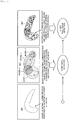
Fig. 1 is a diagram illustrating an overview of a detection apparatus. - [
Fig. 2 ]
Fig. 2 is a diagram illustrating detection by the detection apparatus using coupled normal communication models, and detection using additionally learned normal communication models. - [
Fig. 3 ]
Fig. 3 is a diagram illustrating an example of a configuration of a system that includes the detection apparatus. - [
Fig. 4 ]
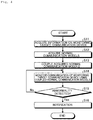
Fig. 4 is a flowchart illustrating an example of a procedure in which the detection apparatus monitors communication of a monitoring target communication device using coupled normal communication models. - [
Fig. 5 ]
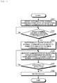
Fig. 5 is a flowchart illustrating an example of a procedure in which the detection apparatus additionally learns the coupled normal communication models, and monitors communication of a monitoring target communication device using the additionally learned normal communication models. - [
Fig. 6 ]
Fig. 6 is a diagram illustrating an example of a computer that executes a detection program. - Hereinafter, an aspect (embodiment) for implementing the present invention will be described with reference to the drawings. The present invention is not limited to the below-described embodiment.
- First, the overview of the
detection apparatus 10 according to the present embodiment will be described with reference toFig. 1 . Here, the description will be given taking a case where communication devices (monitoring target communication devices) that are subjected to abnormality detection by thedetection apparatus 10 are IoT devices, as an example. Also, each of the IoT devices is assumed to be connected to the Internet via a gateway. - First, a system is provided with, for each element (function) constituting an IoT device, models (normal communication models) for determining whether or not the IoT device having this element performs normal communication. The normal communication models are created, for example, by sorting communication information (such as traffic information) when the IoT device performs normal communication according to the element (for example, a camera or a sensor) constituting the IoT device, and using a probability density estimator. The normal communication models are accumulated in, for example, a server (not shown).
- Then, if a new IoT device is added to a monitoring target IoT network, the
detection apparatus 10 acquires information on this IoT device from the gateway or the like (S1). Note that the information that is acquired here is preferably information that can be acquired immediately from the IoT device such as information regarding the machine type of this IoT device, and communication data (traffic information) on this IoT device during a predetermined period of time, for example. Thedetection apparatus 10 determines, based on the acquired information on the IoT device, which combination of existing normal communication models accumulated in the server can detect an abnormality in communication of this IoT device (S2). - After S2, the
detection apparatus 10 acquires, from the server, the normal communication models that can detect an abnormality in the IoT device, couples them together, and starts monitoring communication of the IoT device using the coupled normal communication models (S3). In other words, thedetection apparatus 10 uses the coupled normal communication models to monitor communication of the IoT device, and detect an abnormality, if any, in communication of the IoT device. - After S3, the
detection apparatus 10 absorbs a difference between the coupled normal communication models and actual communication (actual communication of the IoT device), through additional learning (fine-tuning) (S4). - For example, after the start of monitoring communication of the IoT device in S3, if it is determined that normal communication data of the IoT device has been sufficiently accumulated, the
detection apparatus 10 additionally learns the coupled normal communication models based on the communication data. That is, thedetection apparatus 10 additionally learns the coupled normal communication models, so as to be able to perform accurate determination regarding normal communication of the IoT device. - A case is considered in which, as shown in
Fig. 2 for example, the range of normal communication of an IoT device subjected to monitoring by thedetection apparatus 10 is a range denoted by thereference numeral 201. In this case, thedetection apparatus 10 selects, based on information on the monitoring target IoT device, existing normal communication models (models 1 to 4 inFig. 2 ), and couples them together. Then, thedetection apparatus 10 starts initial detection for communication of the monitoring target IoT device using the coupled normal communication models. - Here, there is also a case where the range (indicated by the reference numeral 201) of normal communication performed by the monitoring target IoT device does not match the range of communication determined as normal communication by a model obtained by coupling the
models 1 to 4 together. Accordingly, when normal communication data of the monitoring target IoT device has been accumulated, thedetection apparatus 10 additionally learns, using this communication data, the coupled normal communication models (models 1 to 4 inFig. 2 ). Then, thedetection apparatus 10 starts full-scale detection for communication of the monitoring target IoT device using the additionally learned normal communication model. - In this way, the
detection apparatus 10 first performs initial detection for communication of a monitoring target IoT device using a combination of existing normal communication models. Then, thedetection apparatus 10 additionally learns the existing normal communication models based on normal communication data of the IoT device, and then performs full-scale detection for communication of the IoT device using the additionally learned normal communication models. Accordingly, thedetection apparatus 10 can prevent the IoT device from entering a state (unsecured state) in which it is not being subjected to abnormality detection during a period of time in which thedetection apparatus 10 learns the normal communication models. - The following will describe an example of a configuration of a system including the
detection apparatus 10 with reference toFig. 3 . As shown inFig. 3 for example, the system includes one ormore communication devices 1, agateway 2, aserver 3, and adetection apparatus 10. - Each
communication device 1 is an apparatus that has a communication function, and is, for example, an IoT device that connects to the Internet via thegateway 2, and performs communication. Thegateway 2 is an apparatus that connects eachcommunication device 1 to a network such as the Internet. - The
server 3 includes amodel storage unit 31 in which one or more normal communication models are stored. The normal communication models are models for determining, for each function of thecommunication device 1, whether or not communication of thecommunication device 1 having this function is normal communication. Each normal communication model is realized by, for example, the above-described probability density estimator. - Examples of the normal communication models include a normal communication model relating to a video delivery communication function, a normal communication model relating to a DHCP (Dynamic Host Configuration Protocol) communication function, a normal communication model relating to a management HTTP (Hyper Text Transfer Protocol) communication function, a normal communication model relating to an NTP (Network Time Protocol) communication function, and a normal communication model relating to a temperature notification MQTT (Message Queue Telemetry Transport) communication function.
- If, for example, the communication device 1 (monitoring target communication device 1) that is a monitoring target is a network camera, the
detection apparatus 10 can determine whether or not communication of the network camera is normal, by combining the normal communication model relating to a video delivery communication function, the normal communication model relating to a DHCP communication function, the normal communication model relating to a management HTTP communication function, the normal communication model relating to an NTP communication function, and the like, the functions being included in the network camera. - Also, if the monitoring
target communication device 1 is an IoT sensor having a temperature sensor, thedetection apparatus 10 can determine whether or not communication of the IoT sensor is normal, by combining the normal communication model relating to a DHCP communication function, the normal communication model relating to an NTP communication function, and the like, the functions being included in the IoT sensor. - Note that these normal communication models may be provided for each protocol used by the
communication device 1, or for each machine-model number of thecommunication device 1, for example. The normal communication models may also be provided for each type of the communication device 1 (such as a network camera or a sensor), or for each combination thereof (for example, each "yy" protocol of a device of a machine-model number "xx"). - The
detection apparatus 10 includes an input/output unit 11, astorage unit 12, and acontrol unit 13. The input/output unit 11 serves as an interface when various types of information are transmitted and received via a network. Thestorage unit 12 stores various types of information required for thecontrol unit 13 to operate. Also, thestorage unit 12 stores normal communication models coupled by thecontrol unit 13, normal communication models additionally learned by thecontrol unit 13, and the like. - The
control unit 13 performs overall control of thedetection apparatus 10. Thiscontrol unit 13 includes amodel acquisition unit 131, amodel coupling unit 132, adetection unit 133, and anadditional learning unit 134. - The
model acquisition unit 131 acquires, from theserver 3, at least one normal communication model that corresponds to the function of the monitoringtarget communication device 1. For example, themodel acquisition unit 131 acquires, from the monitoringtarget communication device 1, information regarding the type and the machine-model number of thecommunication device 1, and specifies, based on the information, which functions thecommunication device 1 has. Then, themodel acquisition unit 131 acquires, from theserver 3, a normal communication model that corresponds to each of the specified functions. - For example, a case is considered in which the monitoring
target communication device 1 is a network camera of a machine type A. In this case, themodel acquisition unit 131 specifies the video delivery communication function, the DHCP communication function, the management HTTP communication function, and the NTP communication function, as the functions provided for the network camera of the machine type A. From theserver 3, the normal communication models are acquired that relate to the specified functions, namely, the normal communication model relating to the video delivery communication function, the normal communication model relating to the DHCP communication function, the normal communication model relating to the management HTTP communication function, and the normal communication model relating to the NTP communication function are acquired. - If a plurality of normal communication models are acquired by the
model acquisition unit 131, themodel coupling unit 132 will couple these normal communication models together. For example, if as a normal communication model, a probability density function p (x) is used for calculating the probability density that the communication is normal communication with communication (x) by the monitoringtarget communication device 1 serving as an input, themodel coupling unit 132 will add up the probability density functions p(x) of the normal communication models to be coupled together and thereby couple the normal communication models together. For example, themodel coupling unit 132 adds up the probability density functions p(x) serving as each normal communication models, using the following Expression (1).
[Math. 1]
- The
detection unit 133 monitors communication of the monitoringtarget communication device 1, and detects an abnormality. For example, thedetection unit 133 monitors communication of the monitoringtarget communication device 1 using normal communication models coupled by themodel coupling unit 132, and detects an abnormality. Note that after the coupled normal communication models have been additionally learned by theadditional learning unit 134, thedetection unit 133 monitors communication of the monitoringtarget communication device 1 using the additionally learned normal communication models, and detects an abnormality. - The
additional learning unit 134 additionally learns the normal communication models using normal communication data of the monitoringtarget communication device 1. - For example, if it is determined that a predetermined amount (an amount for, e.g., one day to one week) of normal communication data of the monitoring
target communication device 1 has been accumulated, theadditional learning unit 134 additionally learns the coupled normal communication models using the accumulated communication data. - Note that if a result of analysis of the normal communication data of the monitoring
target communication device 1 performed by theadditional learning unit 134 shows that the coupled normal communication models include an unnecessary normal communication model, the unnecessary normal communication model may be deleted from the coupled normal communication models. - With this measure, the
additional learning unit 134 can change the coupled normal communication models acquired by themodel acquisition unit 131 to a model with a higher detection accuracy. - The above-described
detection apparatus 10 first performs initial detection for communication of a monitoring target IoT device using a combination of existing normal communication models. Then, thedetection apparatus 10 additionally learns the existing normal communication models using normal communication data of the IoT device, and then performs full-scale detection for the communication of the IoT device using the additionally learned normal communication models. Accordingly, thedetection apparatus 10 can prevent the IoT device from entering a state (unsecured state) in which it is not being subjected to abnormality detection during a period of time in which thedetection apparatus 10 learns the normal communication models. - The following will describe an example of a procedure of processing performed by the
detection apparatus 10. First, an example of a procedure in which thedetection apparatus 10 monitors communication of a monitoring target communication device using coupled normal communication models obtained by coupling normal communication models acquired from theserver 3 will be described with reference toFig. 4 . - For example, when the
model acquisition unit 131 of thedetection apparatus 10 acquires information on the monitoringtarget communication device 1 from the gateway 2 (S11), themodel acquisition unit 131 acquires, based on the acquired information, normal communication models that correspond to the function of thiscommunication device 1 from among the normal communication models accumulated in the server 3 (S12). - After S12, the
model coupling unit 132 couples the normal communication models acquired in S12 (S13). Then, thedetection unit 133 monitors communication of the monitoringtarget communication device 1, using the normal communication models coupled in S13 (S14). - For example, upon acquiring communication data of the monitoring
target communication device 1 from thegateway 2, thedetection unit 133 determines whether or not communication of thecommunication device 1 is normal, using the above-described coupled normal communication models. Then, if an abnormality in communication of the monitoringtarget communication device 1 is detected (Yes in S15), thedetection unit 133 perform notification relating to the detection (S16). Also, if no abnormality in communication of the monitoringtarget communication device 1 is detected by the detection unit 133 (No in S15), the procedure returns to S14. - The following will describe an example of a procedure in which, after the processing shown in
Fig. 4 , thedetection apparatus 10 additionally learns the coupled normal communication models, and monitors communication of the monitoring target communication device using the additionally learned normal communication models, with reference toFig. 5 . - After the procedure shown in
Fig. 4 , theadditional learning unit 134 of thedetection apparatus 10 starts accumulating normal communication data of the monitoring target communication device 1 (S21), and, if a predetermined amount of normal communication data is accumulated (Yes in S22), theadditional learning unit 134 additionally learns the coupled normal communication models using the accumulated normal communication data (S23). - After S24, the
detection unit 133 monitors communication of the monitoringtarget communication device 1 using the additionally learned coupled normal communication models (S24). For example, upon acquiring communication data of the monitoringtarget communication device 1 from thegateway 2, thedetection unit 133 determines whether or not communication of thecommunication device 1 is normal, using the additionally learned coupled normal communication models. Then, if an abnormality in communication of the monitoringtarget communication device 1 is detected (Yes in S25), thedetection unit 133 performs notification relating to the detection (S26). Also, if no abnormality in communication of the monitoringtarget communication device 1 is detected by the detection unit 133 (No in S25), the procedure returns to S24. - With this measure, the
detection apparatus 10 can prevent thecommunication device 1 from entering the state (unsecured state) in which it is not being subjected to abnormality detection while thedetection apparatus 10 learns normal communication models relating to communication of the monitoringtarget communication device 1. - Note that the above-described embodiment has described a case where the
detection apparatus 10 acquires a plurality of normal communication models from theserver 3, but the number of normal communication models that are acquired may be one. In this case, thedetection apparatus 10 does not couple the normal communication model, and thedetection unit 133 performs initial detection using the normal communication model acquired from theserver 3. Also, theadditional learning unit 134 performs additional learning of the normal communication model acquired from theserver 3. Then, after the above-described additional learning, thedetection unit 133 performs full-scale detection using the additionally learned normal communication model. - Also, a program for realizing the functions of the
detection apparatus 10 that have been described in the foregoing embodiment can be implemented by being installed in a desired information processing apparatus (computer). For example, the information processing apparatus can function as thedetection apparatus 10 by executing the above-described program provided as package software or online software. The "information processing apparatus" in this context includes a desktop or notebook personal computer, a rack mount server computer, and the like. In addition thereto, the category of the information processing apparatus also includes, for example, a mobile communication terminal such as a smartphone, a cellular phone, and a PHS (Personal Handyphone System), as well as a PDA (Personal Digital Assistant) . Also, thedetection apparatus 10 may also be implemented on a cloud server. - The following will describe an example of a computer that executes the above-described program (detection program), with reference to
Fig. 6 . As shown inFig. 6 , thecomputer 1000 includes, for example, amemory 1010, aCPU 1020, a harddisk drive interface 1030, adisk drive interface 1040, aserial port interface 1050, avideo adapter 1060, and anetwork interface 1070. These components are connected to each other via a bus 1080. - The
memory 1010 includes a ROM (Read Only Memory) 1011 and a RAM (Random Access Memory) 1012. TheROM 1011 stores, for example, a boot program such as a BIOS (Basic Input Output System) . The harddisk drive interface 1030 is connected to ahard disk drive 1090. Thedisk drive interface 1040 is connected to adisk drive 1100. For example, a detachable storage medium such as a magnetic disk or an optical disc is inserted into thedisk drive 1100. For example, amouse 1110 and akeyboard 1120 are connected to theserial port interface 1050. For example, adisplay 1130 is connected to thevideo adapter 1060. - Here, as shown in
Fig. 6 , thehard disk drive 1090 stores, for example, anOS 1091, anapplication program 1092, aprogram module 1093, andprogram data 1094. Various types of data and information described in the foregoing embodiment are stored in thehard disk drive 1090 or thememory 1010, for example. - Also, the
CPU 1020 reads theprogram module 1093 or theprogram data 1094 stored in thehard disk drive 1090 onto the RAM 1012 as needed, and executes the above-described procedures. - Note that the present invention is not limited to the case where the
program module 1093 and theprogram data 1094 according to the above-described detection program are stored in thehard disk drive 1090, but theprogram module 1093 and theprogram data 1094 may be stored in, for example, a detachable storage medium, and read by theCPU 1020 via thedisk drive 1100 or the like. Alternatively, theprogram module 1093 and theprogram data 1094 according to the above-described program may also be stored in another computer connected via a network such as a LAN or a WAN (Wide Area Network), and read by theCPU 1020 via thenetwork interface 1070. -
- 1
- Communication device
- 2
- Gateway
- 3
- Server
- 10
- Detection apparatus
- 11
- Input/output unit
- 12
- Storage unit
- 13
- Control unit
- 131
- Model acquisition unit
- 132
- Model coupling unit
- 133
- Detection unit
- 134
- Additional learning unit
Claims (7)
- A detection apparatus comprising:a model acquisition unit configured to acquire, from a storage unit having stored therein normal communication models for determining, for each function of a communication device, whether or not communication of the communication device having the function is normal, at least one normal communication model that corresponds to a function of a monitoring target communication device; anda detection unit configured to monitor communication of the monitoring target communication device using the acquired normal communication model, and detect an abnormality in the communication.
- The detection apparatus according to claim 1, further including an additional learning unit configured to additionally learn the acquired normal communication model using communication data on normal communication of the monitoring target communication device, wherein
the detection unit is configured to monitor communication of the monitoring target communication device using the additionally learned normal communication model, and detect the abnormality in the communication. - The detection apparatus according to claim 1, further including a model coupling unit configured to couple, if a plurality of normal communication models are acquired, the plurality of acquired normal communication models, wherein
the detection unit is configured to monitor communication of the monitoring target communication device using the coupled normal communication models, and detect the abnormality in the communication. - The detection apparatus according to claim 3, whereinthe normal communication models each include a probability density function of calculating a probability density that communication of the communication device having the function is normal communication, andthe model coupling unit is configured to couple the normal communication models by adding up the probability density functions respectively included in the acquired normal communication models.
- The detection apparatus according to claim 3, further including an additional learning unit configured to additionally learn the coupled normal communication models using communication data on normal communication of the monitoring target communication device, wherein
the detection unit is configured to monitor communication of the monitoring target communication device using the additionally learned coupled normal communication models, and detect the abnormality in the communication. - A detection method performed by a detection apparatus, comprising:a model acquisition step of acquiring, from a storage unit having stored therein normal communication models for determining, for each function of a communication device, whether or not communication of the communication device having the function is normal, at least one normal communication model that corresponds to a function of a monitoring target communication device; anda detection step of monitoring communication of the monitoring target communication device using the acquired normal communication model, and detecting an abnormality in the communication.
- A detection program that causes a computer to execute:a model acquisition step of acquiring, from a storage unit having stored therein normal communication models for determining, for each function of a communication device, whether or not communication of the communication device having the function is normal, at least one normal communication model that corresponds to a function of a monitoring target communication device; anda detection step of monitoring communication of the monitoring target communication device using the acquired normal communication model, and detecting an abnormality in the communication.
Applications Claiming Priority (2)
| Application Number | Priority Date | Filing Date | Title |
|---|---|---|---|
| JP2018237795A JP7127525B2 (en) | 2018-12-19 | 2018-12-19 | DETECTION DEVICE, DETECTION METHOD, AND DETECTION PROGRAM |
| PCT/JP2019/047166 WO2020129610A1 (en) | 2018-12-19 | 2019-12-03 | Detection device, detection method, and detection program |
Publications (3)
| Publication Number | Publication Date |
|---|---|
| EP3883190A1 true EP3883190A1 (en) | 2021-09-22 |
| EP3883190A4 EP3883190A4 (en) | 2022-08-10 |
| EP3883190B1 EP3883190B1 (en) | 2024-03-13 |
Family
ID=71100297
Family Applications (1)
| Application Number | Title | Priority Date | Filing Date |
|---|---|---|---|
| EP19901078.6A Active EP3883190B1 (en) | 2018-12-19 | 2019-12-03 | Detection device, detection method, and detection program |
Country Status (6)
| Country | Link |
|---|---|
| US (1) | US11489746B2 (en) |
| EP (1) | EP3883190B1 (en) |
| JP (1) | JP7127525B2 (en) |
| CN (1) | CN113196707B (en) |
| AU (1) | AU2019404523B2 (en) |
| WO (1) | WO2020129610A1 (en) |
Families Citing this family (3)
| Publication number | Priority date | Publication date | Assignee | Title |
|---|---|---|---|---|
| CN112804336B (en) * | 2020-10-29 | 2022-11-01 | 浙江工商大学 | Fault detection method, device, system and computer readable storage medium |
| WO2022195887A1 (en) * | 2021-03-19 | 2022-09-22 | 日本電信電話株式会社 | Traffic sensor, analysis method, and analysis program |
| EP4333391A4 (en) | 2021-06-07 | 2024-11-27 | Nippon Telegraph And Telephone Corporation | DETECTION DEVICE, DETECTION METHOD AND DETECTION PROGRAM |
Family Cites Families (10)
| Publication number | Priority date | Publication date | Assignee | Title |
|---|---|---|---|---|
| JP4720295B2 (en) | 2005-06-02 | 2011-07-13 | 日本電気株式会社 | Abnormality detection system and maintenance system |
| CN101360023A (en) * | 2008-09-09 | 2009-02-04 | 成都市华为赛门铁克科技有限公司 | Exception detection method, apparatus and system |
| JP6066877B2 (en) * | 2013-09-26 | 2017-01-25 | 株式会社Kddi総合研究所 | Authentication server, authentication method, and authentication program |
| JP2015108898A (en) * | 2013-12-03 | 2015-06-11 | 日本電信電話株式会社 | Abnormality detection system and abnormality detection method |
| US20170147941A1 (en) * | 2015-11-23 | 2017-05-25 | Alexander Bauer | Subspace projection of multi-dimensional unsupervised machine learning models |
| JP6476143B2 (en) * | 2016-02-02 | 2019-02-27 | 日本電信電話株式会社 | Anomaly detection device, anomaly detection system, anomaly detection method, and program |
| US20180096261A1 (en) * | 2016-10-01 | 2018-04-05 | Intel Corporation | Unsupervised machine learning ensemble for anomaly detection |
| WO2018150616A1 (en) * | 2017-02-15 | 2018-08-23 | 日本電信電話株式会社 | Abnormal sound detection device, abnormality degree calculation device, abnormal sound generation device, abnormal sound detection learning device, abnormal signal detection device, abnormal signal detection learning device, and methods and programs therefor |
| JP7017861B2 (en) * | 2017-03-23 | 2022-02-09 | 株式会社日立製作所 | Anomaly detection system and anomaly detection method |
| US10785244B2 (en) * | 2017-12-15 | 2020-09-22 | Panasonic Intellectual Property Corporation Of America | Anomaly detection method, learning method, anomaly detection device, and learning device |
-
2018
- 2018-12-19 JP JP2018237795A patent/JP7127525B2/en active Active
-
2019
- 2019-12-03 CN CN201980082938.3A patent/CN113196707B/en active Active
- 2019-12-03 AU AU2019404523A patent/AU2019404523B2/en active Active
- 2019-12-03 WO PCT/JP2019/047166 patent/WO2020129610A1/en not_active Ceased
- 2019-12-03 EP EP19901078.6A patent/EP3883190B1/en active Active
- 2019-12-03 US US17/413,954 patent/US11489746B2/en active Active
Also Published As
| Publication number | Publication date |
|---|---|
| AU2019404523A1 (en) | 2021-07-01 |
| JP7127525B2 (en) | 2022-08-30 |
| US11489746B2 (en) | 2022-11-01 |
| EP3883190A4 (en) | 2022-08-10 |
| JP2020102671A (en) | 2020-07-02 |
| AU2019404523B2 (en) | 2022-10-20 |
| US20220086074A1 (en) | 2022-03-17 |
| WO2020129610A1 (en) | 2020-06-25 |
| CN113196707A (en) | 2021-07-30 |
| EP3883190B1 (en) | 2024-03-13 |
| CN113196707B (en) | 2024-07-19 |
Similar Documents
| Publication | Publication Date | Title |
|---|---|---|
| CN108900353B (en) | Fault warning method and terminal equipment | |
| EP2875444B1 (en) | Tag latency monitoring and control system for enhanced web page performance | |
| CN110475124B (en) | Video jamming detection method and device | |
| US9117072B2 (en) | Software exploit detection | |
| EP3883190B1 (en) | Detection device, detection method, and detection program | |
| US20160014148A1 (en) | Web anomaly detection apparatus and method | |
| US9524223B2 (en) | Performance metrics of a computer system | |
| JP2008090504A (en) | Computer maintenance support system and analysis server | |
| GB2542370A (en) | A system for monitoring a plurality of distributed devices | |
| US12579248B2 (en) | Systems, devices, and methods for tracking remote equipment location and utilization of computing devices | |
| CN116127230B (en) | Webpage protection rule generation method, device, equipment and medium | |
| CN119165275A (en) | A method, device, equipment and storage medium for detecting electric power equipment | |
| CN117544536A (en) | Dial test methods, devices, electronic equipment and storage media | |
| CN114116128B (en) | Container instance fault diagnosis method, device, equipment and storage medium | |
| CN109036497B (en) | Method and device for analyzing detection result of medical laboratory | |
| CN115267839B (en) | Signal monitoring method, device, system, electronic device and storage medium | |
| CN117978612B (en) | Network fault detection method, storage medium and electronic equipment | |
| CN113596051B (en) | Detection method, detection apparatus, electronic device, medium, and computer program | |
| EP4030324B1 (en) | Level estimation device, level estimation method, and level estimation program | |
| CN120973292A (en) | Data monitoring methods, devices, terminal equipment and storage media | |
| CN112699705B (en) | Information collection method and fault location method, device and electronic equipment | |
| CN117014351A (en) | Network detection method, device, equipment and medium | |
| KR102037002B1 (en) | Method for Estimating Performance of Distributed Data Processing System and Node device for the Distributed Data Processing System | |
| CN115037636A (en) | Service quality perception method and device, electronic equipment and storage medium | |
| CN119537147A (en) | A method, device, equipment and medium for detecting abnormality of application program |
Legal Events
| Date | Code | Title | Description |
|---|---|---|---|
| STAA | Information on the status of an ep patent application or granted ep patent |
Free format text: STATUS: THE INTERNATIONAL PUBLICATION HAS BEEN MADE |
|
| PUAI | Public reference made under article 153(3) epc to a published international application that has entered the european phase |
Free format text: ORIGINAL CODE: 0009012 |
|
| STAA | Information on the status of an ep patent application or granted ep patent |
Free format text: STATUS: REQUEST FOR EXAMINATION WAS MADE |
|
| 17P | Request for examination filed |
Effective date: 20210614 |
|
| AK | Designated contracting states |
Kind code of ref document: A1 Designated state(s): AL AT BE BG CH CY CZ DE DK EE ES FI FR GB GR HR HU IE IS IT LI LT LU LV MC MK MT NL NO PL PT RO RS SE SI SK SM TR |
|
| DAV | Request for validation of the european patent (deleted) | ||
| DAX | Request for extension of the european patent (deleted) | ||
| REG | Reference to a national code |
Ref country code: DE Ref legal event code: R079 Free format text: PREVIOUS MAIN CLASS: H04L0012260000 Ipc: G06N0020000000 Ref country code: DE Ref legal event code: R079 Ref document number: 602019048426 Country of ref document: DE Free format text: PREVIOUS MAIN CLASS: H04L0012260000 Ipc: G06N0020000000 |
|
| A4 | Supplementary search report drawn up and despatched |
Effective date: 20220712 |
|
| RIC1 | Information provided on ipc code assigned before grant |
Ipc: H04L 12/00 20060101ALI20220706BHEP Ipc: G06N 20/00 20190101AFI20220706BHEP |
|
| STAA | Information on the status of an ep patent application or granted ep patent |
Free format text: STATUS: EXAMINATION IS IN PROGRESS |
|
| 17Q | First examination report despatched |
Effective date: 20230215 |
|
| GRAP | Despatch of communication of intention to grant a patent |
Free format text: ORIGINAL CODE: EPIDOSNIGR1 |
|
| STAA | Information on the status of an ep patent application or granted ep patent |
Free format text: STATUS: GRANT OF PATENT IS INTENDED |
|
| INTG | Intention to grant announced |
Effective date: 20231127 |
|
| GRAS | Grant fee paid |
Free format text: ORIGINAL CODE: EPIDOSNIGR3 |
|
| GRAA | (expected) grant |
Free format text: ORIGINAL CODE: 0009210 |
|
| STAA | Information on the status of an ep patent application or granted ep patent |
Free format text: STATUS: THE PATENT HAS BEEN GRANTED |
|
| AK | Designated contracting states |
Kind code of ref document: B1 Designated state(s): AL AT BE BG CH CY CZ DE DK EE ES FI FR GB GR HR HU IE IS IT LI LT LU LV MC MK MT NL NO PL PT RO RS SE SI SK SM TR |
|
| REG | Reference to a national code |
Ref country code: GB Ref legal event code: FG4D |
|
| REG | Reference to a national code |
Ref country code: CH Ref legal event code: EP |
|
| REG | Reference to a national code |
Ref country code: DE Ref legal event code: R096 Ref document number: 602019048426 Country of ref document: DE |
|
| REG | Reference to a national code |
Ref country code: IE Ref legal event code: FG4D |
|
| REG | Reference to a national code |
Ref country code: SE Ref legal event code: TRGR |
|
| PG25 | Lapsed in a contracting state [announced via postgrant information from national office to epo] |
Ref country code: LT Free format text: LAPSE BECAUSE OF FAILURE TO SUBMIT A TRANSLATION OF THE DESCRIPTION OR TO PAY THE FEE WITHIN THE PRESCRIBED TIME-LIMIT Effective date: 20240313 |
|
| REG | Reference to a national code |
Ref country code: LT Ref legal event code: MG9D |
|
| PG25 | Lapsed in a contracting state [announced via postgrant information from national office to epo] |
Ref country code: GR Free format text: LAPSE BECAUSE OF FAILURE TO SUBMIT A TRANSLATION OF THE DESCRIPTION OR TO PAY THE FEE WITHIN THE PRESCRIBED TIME-LIMIT Effective date: 20240614 |
|
| REG | Reference to a national code |
Ref country code: NL Ref legal event code: MP Effective date: 20240313 |
|
| PG25 | Lapsed in a contracting state [announced via postgrant information from national office to epo] |
Ref country code: HR Free format text: LAPSE BECAUSE OF FAILURE TO SUBMIT A TRANSLATION OF THE DESCRIPTION OR TO PAY THE FEE WITHIN THE PRESCRIBED TIME-LIMIT Effective date: 20240313 Ref country code: RS Free format text: LAPSE BECAUSE OF FAILURE TO SUBMIT A TRANSLATION OF THE DESCRIPTION OR TO PAY THE FEE WITHIN THE PRESCRIBED TIME-LIMIT Effective date: 20240613 |
|
| PG25 | Lapsed in a contracting state [announced via postgrant information from national office to epo] |
Ref country code: ES Free format text: LAPSE BECAUSE OF FAILURE TO SUBMIT A TRANSLATION OF THE DESCRIPTION OR TO PAY THE FEE WITHIN THE PRESCRIBED TIME-LIMIT Effective date: 20240313 |
|
| PG25 | Lapsed in a contracting state [announced via postgrant information from national office to epo] |
Ref country code: RS Free format text: LAPSE BECAUSE OF FAILURE TO SUBMIT A TRANSLATION OF THE DESCRIPTION OR TO PAY THE FEE WITHIN THE PRESCRIBED TIME-LIMIT Effective date: 20240613 Ref country code: NO Free format text: LAPSE BECAUSE OF FAILURE TO SUBMIT A TRANSLATION OF THE DESCRIPTION OR TO PAY THE FEE WITHIN THE PRESCRIBED TIME-LIMIT Effective date: 20240613 Ref country code: LT Free format text: LAPSE BECAUSE OF FAILURE TO SUBMIT A TRANSLATION OF THE DESCRIPTION OR TO PAY THE FEE WITHIN THE PRESCRIBED TIME-LIMIT Effective date: 20240313 Ref country code: HR Free format text: LAPSE BECAUSE OF FAILURE TO SUBMIT A TRANSLATION OF THE DESCRIPTION OR TO PAY THE FEE WITHIN THE PRESCRIBED TIME-LIMIT Effective date: 20240313 Ref country code: GR Free format text: LAPSE BECAUSE OF FAILURE TO SUBMIT A TRANSLATION OF THE DESCRIPTION OR TO PAY THE FEE WITHIN THE PRESCRIBED TIME-LIMIT Effective date: 20240614 Ref country code: FI Free format text: LAPSE BECAUSE OF FAILURE TO SUBMIT A TRANSLATION OF THE DESCRIPTION OR TO PAY THE FEE WITHIN THE PRESCRIBED TIME-LIMIT Effective date: 20240313 Ref country code: ES Free format text: LAPSE BECAUSE OF FAILURE TO SUBMIT A TRANSLATION OF THE DESCRIPTION OR TO PAY THE FEE WITHIN THE PRESCRIBED TIME-LIMIT Effective date: 20240313 Ref country code: BG Free format text: LAPSE BECAUSE OF FAILURE TO SUBMIT A TRANSLATION OF THE DESCRIPTION OR TO PAY THE FEE WITHIN THE PRESCRIBED TIME-LIMIT Effective date: 20240313 |
|
| REG | Reference to a national code |
Ref country code: AT Ref legal event code: MK05 Ref document number: 1666466 Country of ref document: AT Kind code of ref document: T Effective date: 20240313 |
|
| PG25 | Lapsed in a contracting state [announced via postgrant information from national office to epo] |
Ref country code: LV Free format text: LAPSE BECAUSE OF FAILURE TO SUBMIT A TRANSLATION OF THE DESCRIPTION OR TO PAY THE FEE WITHIN THE PRESCRIBED TIME-LIMIT Effective date: 20240313 |
|
| PG25 | Lapsed in a contracting state [announced via postgrant information from national office to epo] |
Ref country code: NL Free format text: LAPSE BECAUSE OF FAILURE TO SUBMIT A TRANSLATION OF THE DESCRIPTION OR TO PAY THE FEE WITHIN THE PRESCRIBED TIME-LIMIT Effective date: 20240313 |
|
| PG25 | Lapsed in a contracting state [announced via postgrant information from national office to epo] |
Ref country code: NL Free format text: LAPSE BECAUSE OF FAILURE TO SUBMIT A TRANSLATION OF THE DESCRIPTION OR TO PAY THE FEE WITHIN THE PRESCRIBED TIME-LIMIT Effective date: 20240313 |
|
| PG25 | Lapsed in a contracting state [announced via postgrant information from national office to epo] |
Ref country code: IS Free format text: LAPSE BECAUSE OF FAILURE TO SUBMIT A TRANSLATION OF THE DESCRIPTION OR TO PAY THE FEE WITHIN THE PRESCRIBED TIME-LIMIT Effective date: 20240713 |
|
| PG25 | Lapsed in a contracting state [announced via postgrant information from national office to epo] |
Ref country code: SM Free format text: LAPSE BECAUSE OF FAILURE TO SUBMIT A TRANSLATION OF THE DESCRIPTION OR TO PAY THE FEE WITHIN THE PRESCRIBED TIME-LIMIT Effective date: 20240313 Ref country code: PT Free format text: LAPSE BECAUSE OF FAILURE TO SUBMIT A TRANSLATION OF THE DESCRIPTION OR TO PAY THE FEE WITHIN THE PRESCRIBED TIME-LIMIT Effective date: 20240715 |
|
| PG25 | Lapsed in a contracting state [announced via postgrant information from national office to epo] |
Ref country code: CZ Free format text: LAPSE BECAUSE OF FAILURE TO SUBMIT A TRANSLATION OF THE DESCRIPTION OR TO PAY THE FEE WITHIN THE PRESCRIBED TIME-LIMIT Effective date: 20240313 Ref country code: EE Free format text: LAPSE BECAUSE OF FAILURE TO SUBMIT A TRANSLATION OF THE DESCRIPTION OR TO PAY THE FEE WITHIN THE PRESCRIBED TIME-LIMIT Effective date: 20240313 |
|
| PG25 | Lapsed in a contracting state [announced via postgrant information from national office to epo] |
Ref country code: AT Free format text: LAPSE BECAUSE OF FAILURE TO SUBMIT A TRANSLATION OF THE DESCRIPTION OR TO PAY THE FEE WITHIN THE PRESCRIBED TIME-LIMIT Effective date: 20240313 |
|
| PG25 | Lapsed in a contracting state [announced via postgrant information from national office to epo] |
Ref country code: PL Free format text: LAPSE BECAUSE OF FAILURE TO SUBMIT A TRANSLATION OF THE DESCRIPTION OR TO PAY THE FEE WITHIN THE PRESCRIBED TIME-LIMIT Effective date: 20240313 |
|
| PG25 | Lapsed in a contracting state [announced via postgrant information from national office to epo] |
Ref country code: SK Free format text: LAPSE BECAUSE OF FAILURE TO SUBMIT A TRANSLATION OF THE DESCRIPTION OR TO PAY THE FEE WITHIN THE PRESCRIBED TIME-LIMIT Effective date: 20240313 |
|
| PG25 | Lapsed in a contracting state [announced via postgrant information from national office to epo] |
Ref country code: SM Free format text: LAPSE BECAUSE OF FAILURE TO SUBMIT A TRANSLATION OF THE DESCRIPTION OR TO PAY THE FEE WITHIN THE PRESCRIBED TIME-LIMIT Effective date: 20240313 Ref country code: SK Free format text: LAPSE BECAUSE OF FAILURE TO SUBMIT A TRANSLATION OF THE DESCRIPTION OR TO PAY THE FEE WITHIN THE PRESCRIBED TIME-LIMIT Effective date: 20240313 Ref country code: RO Free format text: LAPSE BECAUSE OF FAILURE TO SUBMIT A TRANSLATION OF THE DESCRIPTION OR TO PAY THE FEE WITHIN THE PRESCRIBED TIME-LIMIT Effective date: 20240313 Ref country code: PT Free format text: LAPSE BECAUSE OF FAILURE TO SUBMIT A TRANSLATION OF THE DESCRIPTION OR TO PAY THE FEE WITHIN THE PRESCRIBED TIME-LIMIT Effective date: 20240715 Ref country code: PL Free format text: LAPSE BECAUSE OF FAILURE TO SUBMIT A TRANSLATION OF THE DESCRIPTION OR TO PAY THE FEE WITHIN THE PRESCRIBED TIME-LIMIT Effective date: 20240313 Ref country code: IS Free format text: LAPSE BECAUSE OF FAILURE TO SUBMIT A TRANSLATION OF THE DESCRIPTION OR TO PAY THE FEE WITHIN THE PRESCRIBED TIME-LIMIT Effective date: 20240713 Ref country code: EE Free format text: LAPSE BECAUSE OF FAILURE TO SUBMIT A TRANSLATION OF THE DESCRIPTION OR TO PAY THE FEE WITHIN THE PRESCRIBED TIME-LIMIT Effective date: 20240313 Ref country code: CZ Free format text: LAPSE BECAUSE OF FAILURE TO SUBMIT A TRANSLATION OF THE DESCRIPTION OR TO PAY THE FEE WITHIN THE PRESCRIBED TIME-LIMIT Effective date: 20240313 Ref country code: AT Free format text: LAPSE BECAUSE OF FAILURE TO SUBMIT A TRANSLATION OF THE DESCRIPTION OR TO PAY THE FEE WITHIN THE PRESCRIBED TIME-LIMIT Effective date: 20240313 |
|
| REG | Reference to a national code |
Ref country code: DE Ref legal event code: R097 Ref document number: 602019048426 Country of ref document: DE |
|
| PG25 | Lapsed in a contracting state [announced via postgrant information from national office to epo] |
Ref country code: DK Free format text: LAPSE BECAUSE OF FAILURE TO SUBMIT A TRANSLATION OF THE DESCRIPTION OR TO PAY THE FEE WITHIN THE PRESCRIBED TIME-LIMIT Effective date: 20240313 |
|
| PLBE | No opposition filed within time limit |
Free format text: ORIGINAL CODE: 0009261 |
|
| STAA | Information on the status of an ep patent application or granted ep patent |
Free format text: STATUS: NO OPPOSITION FILED WITHIN TIME LIMIT |
|
| PG25 | Lapsed in a contracting state [announced via postgrant information from national office to epo] |
Ref country code: DK Free format text: LAPSE BECAUSE OF FAILURE TO SUBMIT A TRANSLATION OF THE DESCRIPTION OR TO PAY THE FEE WITHIN THE PRESCRIBED TIME-LIMIT Effective date: 20240313 |
|
| 26N | No opposition filed |
Effective date: 20241216 |
|
| PG25 | Lapsed in a contracting state [announced via postgrant information from national office to epo] |
Ref country code: SI Free format text: LAPSE BECAUSE OF FAILURE TO SUBMIT A TRANSLATION OF THE DESCRIPTION OR TO PAY THE FEE WITHIN THE PRESCRIBED TIME-LIMIT Effective date: 20240313 |
|
| PG25 | Lapsed in a contracting state [announced via postgrant information from national office to epo] |
Ref country code: MC Free format text: LAPSE BECAUSE OF FAILURE TO SUBMIT A TRANSLATION OF THE DESCRIPTION OR TO PAY THE FEE WITHIN THE PRESCRIBED TIME-LIMIT Effective date: 20240313 |
|
| REG | Reference to a national code |
Ref country code: CH Ref legal event code: PL |
|
| PG25 | Lapsed in a contracting state [announced via postgrant information from national office to epo] |
Ref country code: LU Free format text: LAPSE BECAUSE OF NON-PAYMENT OF DUE FEES Effective date: 20241203 |
|
| REG | Reference to a national code |
Ref country code: BE Ref legal event code: MM Effective date: 20241231 |
|
| PG25 | Lapsed in a contracting state [announced via postgrant information from national office to epo] |
Ref country code: BE Free format text: LAPSE BECAUSE OF NON-PAYMENT OF DUE FEES Effective date: 20241231 |
|
| PG25 | Lapsed in a contracting state [announced via postgrant information from national office to epo] |
Ref country code: CH Free format text: LAPSE BECAUSE OF NON-PAYMENT OF DUE FEES Effective date: 20241231 |
|
| PG25 | Lapsed in a contracting state [announced via postgrant information from national office to epo] |
Ref country code: IE Free format text: LAPSE BECAUSE OF NON-PAYMENT OF DUE FEES Effective date: 20241203 |
|
| PGFP | Annual fee paid to national office [announced via postgrant information from national office to epo] |
Ref country code: DE Payment date: 20251211 Year of fee payment: 7 |
|
| PGFP | Annual fee paid to national office [announced via postgrant information from national office to epo] |
Ref country code: GB Payment date: 20251219 Year of fee payment: 7 |
|
| PGFP | Annual fee paid to national office [announced via postgrant information from national office to epo] |
Ref country code: IT Payment date: 20251223 Year of fee payment: 7 |
|
| PGFP | Annual fee paid to national office [announced via postgrant information from national office to epo] |
Ref country code: FR Payment date: 20251229 Year of fee payment: 7 |
|
| PGFP | Annual fee paid to national office [announced via postgrant information from national office to epo] |
Ref country code: SE Payment date: 20251219 Year of fee payment: 7 |
|
| REG | Reference to a national code |
Ref country code: DE Ref legal event code: R081 Ref document number: 602019048426 Country of ref document: DE Owner name: NTT, INC., JP Free format text: FORMER OWNER: NIPPON TELEGRAPH AND TELEPHONE CORPORATION, TOKYO, JP Ref country code: DE Ref legal event code: R082 Ref document number: 602019048426 Country of ref document: DE Representative=s name: DENNEMEYER & ASSOCIATES RECHTSANWALTSGESELLSCH, DE |
|
| PG25 | Lapsed in a contracting state [announced via postgrant information from national office to epo] |
Ref country code: CY Free format text: LAPSE BECAUSE OF FAILURE TO SUBMIT A TRANSLATION OF THE DESCRIPTION OR TO PAY THE FEE WITHIN THE PRESCRIBED TIME-LIMIT; INVALID AB INITIO Effective date: 20191203 |