EP3883098A1 - Wiring apparatus for motor and corresponding motor - Google Patents
Wiring apparatus for motor and corresponding motor Download PDFInfo
- Publication number
- EP3883098A1 EP3883098A1 EP21160507.6A EP21160507A EP3883098A1 EP 3883098 A1 EP3883098 A1 EP 3883098A1 EP 21160507 A EP21160507 A EP 21160507A EP 3883098 A1 EP3883098 A1 EP 3883098A1
- Authority
- EP
- European Patent Office
- Prior art keywords
- motor
- annular member
- wiring
- holes
- wiring apparatus
- Prior art date
- Legal status (The legal status is an assumption and is not a legal conclusion. Google has not performed a legal analysis and makes no representation as to the accuracy of the status listed.)
- Pending
Links
Images




Classifications
-
- H—ELECTRICITY
- H02—GENERATION; CONVERSION OR DISTRIBUTION OF ELECTRIC POWER
- H02K—DYNAMO-ELECTRIC MACHINES
- H02K3/00—Details of windings
- H02K3/46—Fastening of windings on the stator or rotor structure
- H02K3/50—Fastening of winding heads, equalising connectors, or connections thereto
-
- H—ELECTRICITY
- H02—GENERATION; CONVERSION OR DISTRIBUTION OF ELECTRIC POWER
- H02K—DYNAMO-ELECTRIC MACHINES
- H02K3/00—Details of windings
- H02K3/46—Fastening of windings on the stator or rotor structure
- H02K3/52—Fastening salient pole windings or connections thereto
- H02K3/521—Fastening salient pole windings or connections thereto applicable to stators only
- H02K3/522—Fastening salient pole windings or connections thereto applicable to stators only for generally annular cores with salient poles
-
- H—ELECTRICITY
- H02—GENERATION; CONVERSION OR DISTRIBUTION OF ELECTRIC POWER
- H02K—DYNAMO-ELECTRIC MACHINES
- H02K3/00—Details of windings
- H02K3/02—Windings characterised by the conductor material
-
- H—ELECTRICITY
- H02—GENERATION; CONVERSION OR DISTRIBUTION OF ELECTRIC POWER
- H02K—DYNAMO-ELECTRIC MACHINES
- H02K5/00—Casings; Enclosures; Supports
- H02K5/04—Casings or enclosures characterised by the shape, form or construction thereof
- H02K5/22—Auxiliary parts of casings not covered by groups H02K5/06-H02K5/20, e.g. shaped to form connection boxes or terminal boxes
-
- H—ELECTRICITY
- H02—GENERATION; CONVERSION OR DISTRIBUTION OF ELECTRIC POWER
- H02K—DYNAMO-ELECTRIC MACHINES
- H02K2203/00—Specific aspects not provided for in the other groups of this subclass relating to the windings
- H02K2203/03—Machines characterised by the wiring boards, i.e. printed circuit boards or similar structures for connecting the winding terminations
-
- H—ELECTRICITY
- H02—GENERATION; CONVERSION OR DISTRIBUTION OF ELECTRIC POWER
- H02K—DYNAMO-ELECTRIC MACHINES
- H02K2203/00—Specific aspects not provided for in the other groups of this subclass relating to the windings
- H02K2203/06—Machines characterised by the wiring leads, i.e. conducting wires for connecting the winding terminations
-
- H—ELECTRICITY
- H02—GENERATION; CONVERSION OR DISTRIBUTION OF ELECTRIC POWER
- H02K—DYNAMO-ELECTRIC MACHINES
- H02K2203/00—Specific aspects not provided for in the other groups of this subclass relating to the windings
- H02K2203/09—Machines characterised by wiring elements other than wires, e.g. bus rings, for connecting the winding terminations
Definitions
- Embodiments of the present disclosure generally relate to a field of motors, and more particularly to a wiring apparatus for a winding end of a servo motor.
- Servo motors have a wide range of applications, for example, industrial robots, especially small and medium-sized AC servo motors.
- Servo motors are characterized by a compact structure, a large batch, and a high cost performance.
- the motor is required to be as small and seventeen as possible. There is also a high requirement for automation of manufacturing.
- connection structure for a stator winding wiring ring of an AC motor.
- This structure is sequentially, from the outside to the inside, arranged with three external wiring rings, an insulating layer skeleton and an internal wiring ring.
- Embodiments of the present disclosure provide a wiring apparatus for a motor and a corresponding motor, which intend to at least partially solve the above and/or other potential problems in the design of the wiring of the motor.
- inventions of the present disclosure provide a wiring apparatus for a motor.
- the wiring apparatus comprises an annular member having a first side adjacent to a motor and a second side opposite to the first side; and a conductor embedded in the annular member and comprising a plurality of joints coupled to each other via a conductive bar; wherein the annular member comprises a first group of holes and a second group of holes, the first group of holes each extending from the first side to the plurality of joints, the second group of holes arranged opposite to the first set of holes and each extending from the second side to the plurality of joints.
- the wiring apparatus has a compact structure and reliable wiring. Moreover, the wiring process does not require additional crimping and other procedures, which greatly improves the wiring efficiency.
- the annular member further comprises a groove arranged at a periphery of the annular member and extending from the first side to the second side, the groove being adapted for an enameled wire of the motor to pass through from the first side to enter the second set of holes on the second side, so as to be connected to the joint.
- the annular member further comprises a welding hole provided at a periphery of the annular member and extending from the first side to the second side, the welding hole being adapted for a lead wire of the motor to pass through to be welded to the lead wire.
- the welding hole comprises a plurality of welding holes arranged adjacent to each other at the periphery of the annular member.
- the wiring apparatus further comprises a protrusion adjacent to a periphery of the annular member and extending from the first side toward the motor so as to be inserted into a recess of the periphery of a stator of the motor.
- the conductor is made of a metal comprising copper.
- the annular member is made of an insulating material.
- the conductive bar is helically arranged in the annular member and is insulated from outside by the annular member.
- embodiments of the present disclosure comprise a motor.
- the motor comprises the wiring apparatus according to the first aspect.
- an enameled wire and a lead wire of the winding adopt the traditional connection method, which is cumbersome and cannot be achieved automatically.
- the thickness of a motor winding terminal is increased, which is not conducive to heat dissipation of a motor.
- the present disclosure provides wiring apparatus with a simple structure and which is easy to realize automatic wiring.
- Embodiment of the present disclosure relate to a wiring apparatus 1 for a motor 2.
- the wiring apparatus 1 generally comprises an annular member 10 and a conductor 20 embedded in the annular member 10.
- the annular member 10 is arranged near a leading-out terminal of a winding of the motor 2 and has a first side 12 adjacent to the motor 2 and a second side 14 opposite to the first side 12.
- FIG. 4 is a cross sectional view of a part of the annular member 10.
- the conductor 20 is embedded in the annular member 10 and is surrounded by the annular member 10.
- the conductor 20 comprises a conductive bar 24 and a plurality of joints 22 coupled to each other via the conductive bar 24.
- the annular member 10 comprises a first group of holes 16 and a second group of holes 18 arranged opposite to the first set of holes 16.
- the first group of holes 16 each extends from the first side 12 to the plurality of joints 22.
- the second group of holes 18 each extend from the second side 14 to the plurality of joints 22.
- each hole in the first set of holes 16 and each hole in the second set of holes 18 extend from opposite sides to the corresponding joints 22.
- an enameled wire 4 of the motor 2 can be coupled together in a predetermined manner through the joints 22.
- the annular member 10 can be designed to have a smaller size (i.e., thickness) in a direction L substantially parallel to the axial direction of the motor 2. In this way, when the wiring apparatus 1 realizes a wiring function of the motor 2, no additional space in the direction L is required, making the structure of the motor 2 more compact. Such a configuration is beneficial in small and medium-sized servo motors.
- a plurality of enameled wires 4 of the motor 2 may extend from the motor 2 and be connected to the joints 22 via one side of the wiring apparatus 1 close to the motor 2.
- the enameled wire 4 is inserted into the corresponding first set of holes 16 from the first side 12 of the annular member 10 of the wiring apparatus 1 substantially along the direction L and is coupled to the corresponding joints 22. Since the joints 22 are coupled to each other through the conductive bar 24, in this way, the plurality of enameled wires 4 can be coupled to each other in a predetermined manner.
- Such a wiring method is called multiple parallel wiring.
- the plurality of enameled wires 4 of the motor 2 may also be connected to the joints 22 via a side of the wiring apparatus 1 away from the motor 2.
- the annular member 10 may further comprise a groove 15 provided at the periphery thereof.
- the groove 15 extends from the first side 12 to the second side 14 for the enameled wires 4 of the motor 2 to pass through from the first side 12.
- the enameled wires 4 can thus be connected to the joints 22 via the second set of holes 18 on the second side 14. Since the joints 22 are coupled to each other via the conductive bar 24, in this way, the plurality of enameled wires 4 can be coupled to each other in a predetermined manner.
- Such a wiring method is called one-way parallel wiring.
- the enameled wires 4 can be connected to the wiring apparatus 1 from different directions, thereby achieving a flexible wiring. In this way, users are allowed to adopt a corresponding wiring method according to a specific usage environment, and the applicability of the wiring apparatus 1 is improved.
- the annular member 10 may further comprise a welding hole 13 provided at the periphery of the annular member 10.
- the welding hole 13 extends from the first side 12 to the second side 14 and is adapted for a lead wire 3 of the motor 2 to pass through to be welded to the lead wire 3.
- FIGS. 6 and 7 show the states where the welding hole 13 and the lead wire 3 are welded.
- users can first approach the wiring apparatus 1 to the motor 2 and then align the lead wire 3 with the welding hole 13 and then pass the lead wire 3 through the welding hole 13 so as to realize the welding of the lead wire 3 and the welding hole 13.
- users can connect the enameled wire 4 to the joints 20 of the motor 2 either from the first set of holes 16 on the first side 12 or from the second set of holes 18 on the second side 12 according to the predetermined wiring method.
- the lead wire 3 can be directly welded on the wiring apparatus 1 neatly and compactly so as to save the space for a leading out a wire.
- the welding holes 13 may comprise a plurality of welding holes 13 arranged adjacent to each other at the periphery of the annular member 10.
- the welding holes 13 may be provided at the periphery of the annular member 10 adjacent to each other.
- FIG. 2 it is clear that users can change the number of welding holes 13 according to specific requirements, for example, two or four. The specific number is not limited by embodiments of the present invention.
- the wiring apparatus 1 may further comprise a protrusion 30 adjacent to the periphery of the annular member 10.
- the protrusion 30 extends from the first side 12 close to the motor 2 toward the motor 2.
- a recess 40 is provided at the periphery of the stator of the motor 2, and the position and size of the recess 40 are designed to match the protrusion 30 to facilitate the insertion of the protrusion 30 into the recess 40, in order to realize the connection of the wiring apparatus 1 and the motor 2.
- the recess 40 may be provided at a terminal of a stator core insulation frame of the motor 2. In use, users can weld the lead wire 3 to the welding hole 13 after inserting the protrusion 30 of the wiring apparatus 1 into the recess 40 of the motor 2.
- the protrusions 30 are arranged at an edge of the annular member 10, the radial dimension of the annular member 10 will not be increased.
- the space in the recess 40 of the motor 2 is properly used for coupling with the protrusion 30. Therefore, when the wiring apparatus 1 and the motor 2 are assembled, the size of the assembled wiring apparatus 1 and the motor 2 in the direction L will not be increased. In this way, the size of the motor 2 can be more compact and such a compact design can speed up heat dissipation from the motor 2.
- the wiring apparatus 1 and the motor 2 can be connected in other ways, such as a snap connection, a magnetic connection, and so on.
- the specific manner of connection can be adjusted according to actual needs, and is not limited by embodiments of the present disclosure. In this way, the connection of the device 1 and the motor 2 can be firmly connected without increasing the size of the motor 2. Therefore, the potential safety hazards caused by weak wiring can be avoided.
- the conductor 20 may be made of a metal comprising copper. Copper can ensure a stable connection among the various joints 22 of the conductor 20. In alternative embodiments, other materials may be used in addition to copper, such as aluminum. Users can choose appropriate materials according to actual needs, such as cost considerations. The specific materials are not limited by embodiments of the present disclosure.
- the annular member 10 may be made of an insulating material.
- the insulating material can be resin or plastic. It is to be understood that the annular member 10 can be made of materials other than the materials listed here, as long as the material can achieve an insulating effect.
- FIG. 5 shows an arrangement of the conductor 20 embedded in the annular member 10.
- the conductive bar 24 may be spirally arranged in the annular member 10 and insulated from the outside by the annular member 10. According to different wiring requirements, the corresponding arrangement of the conductive bar 24 can be designed in advance. Users only need to connect the enameled wire 4 of the motor 20 through the first set of holes 16 or the second set of holes 18 of the annular member 10 to couple with the joints 22 to complete the wiring without crimping or welding. This greatly improves the efficiency of automatic wiring. In addition, since the enameled wire 4 does not need an insulation protection such as insulation sleeves, crimp terminals, insulation tapes, etc., the cost of wiring can be reduced.
- the spiral arrangement can make use of the space of the annular member 10 to the maximal content without increasing the size of the wiring apparatus 1.
- the thickness and the width of the conductive bar 24 can be adjusted according to output current and installation space of the motor 2.
- the conductive bars 24 may be arranged along the circumferential direction of the annular member 10 according to the principle of the shortest distance and no crossing. Although the number of the joints 22 on the conductive bar 24 is shown in FIG. 5 , it is to be understood that the number shown here is only illustrative, and the specific number is not limited by embodiments of the present disclosure.
- several supporting bars 26 may be provided between the conductive bars 24.
- the supporting bars 26 ensure the integrity of the conductive bars 24 during the injection molding process so that the conductive bars 24 can be set in a predetermined position.
- the supporting bars 26 ensure relative electrical insulation distance between the conductive bars 24, thereby improving the electrical performance of the conductive bars 24.
- the supporting bars 26 may be removed.
- Embodiments of the present disclosure relates to the motor 2.
- the motor 2 comprises the wiring apparatus 1 discussed above.
- the motor 2 may be a servo motor used on an industrial robot.
- the motor 2 may be a small and medium-sized AC servo motor having concentrated windings.
- the wiring apparatus 1 of the present disclosure due to its compact structure, the thickness of a leading-out terminal of the winding terminal of the motor 2 can be reduced, thereby making the design of the motor 2 more compact and reliable.
- the present disclosure can make the wiring of the enameled wire 4 and the lead wire 3 of the motor 2 simpler, which can realize automatic wiring to match the process flow of the production line. This is beneficial to mass production.
Landscapes
- Engineering & Computer Science (AREA)
- Power Engineering (AREA)
- Motor Or Generator Frames (AREA)
- Insulation, Fastening Of Motor, Generator Windings (AREA)
Abstract
Description
- Embodiments of the present disclosure generally relate to a field of motors, and more particularly to a wiring apparatus for a winding end of a servo motor.
- Servo motors have a wide range of applications, for example, industrial robots, especially small and medium-sized AC servo motors. Servo motors are characterized by a compact structure, a large batch, and a high cost performance. The motor is required to be as small and exquisite as possible. There is also a high requirement for automation of manufacturing.
- In the conventional motor technology, wiring of the winding end is usually cumbersome and less efficient. For small and medium-sized servo motors with concentrated windings, traditional wiring methods make ends of motor windings thicker, which is unfavorable to a compact design of the servo motor. Especially when the axial size of the motor is strictly limited, an excessively large wiring height of the winding end limits the length of a motor core, which makes the motor design more difficult.
- For example, in the existing Chinese patent application
CN 105119411A , there is provided a connection structure for a stator winding wiring ring of an AC motor. This structure is sequentially, from the outside to the inside, arranged with three external wiring rings, an insulating layer skeleton and an internal wiring ring. With such a structure, there are a large number of components and an additional pressing operation on the enameled wire is required, resulting in a complicated process and inefficient wiring In addition, due to the fact that the method for wiring is single, the application range of this connection structure is greatly restricted. - Embodiments of the present disclosure provide a wiring apparatus for a motor and a corresponding motor, which intend to at least partially solve the above and/or other potential problems in the design of the wiring of the motor.
- In a first aspect, embodiments of the present disclosure provide a wiring apparatus for a motor. The wiring apparatus comprises an annular member having a first side adjacent to a motor and a second side opposite to the first side; and a conductor embedded in the annular member and comprising a plurality of joints coupled to each other via a conductive bar; wherein the annular member comprises a first group of holes and a second group of holes, the first group of holes each extending from the first side to the plurality of joints, the second group of holes arranged opposite to the first set of holes and each extending from the second side to the plurality of joints.
- According to embodiments of the present disclosure, the wiring apparatus has a compact structure and reliable wiring. Moreover, the wiring process does not require additional crimping and other procedures, which greatly improves the wiring efficiency.
- In some embodiments, the annular member further comprises a groove arranged at a periphery of the annular member and extending from the first side to the second side, the groove being adapted for an enameled wire of the motor to pass through from the first side to enter the second set of holes on the second side, so as to be connected to the joint.
- In some embodiments, the annular member further comprises a welding hole provided at a periphery of the annular member and extending from the first side to the second side, the welding hole being adapted for a lead wire of the motor to pass through to be welded to the lead wire.
- In some embodiments, the welding hole comprises a plurality of welding holes arranged adjacent to each other at the periphery of the annular member.
- In some embodiments, the wiring apparatus further comprises a protrusion adjacent to a periphery of the annular member and extending from the first side toward the motor so as to be inserted into a recess of the periphery of a stator of the motor.
- In some embodiments, the conductor is made of a metal comprising copper.
- In some embodiments, the annular member is made of an insulating material.
- In some embodiments, wherein the conductive bar is helically arranged in the annular member and is insulated from outside by the annular member.
- In a second aspect, embodiments of the present disclosure comprise a motor. The motor comprises the wiring apparatus according to the first aspect.
- Through the following detailed description with reference to the accompanying drawings, the above and other objectives, features, and advantages of embodiments of the present disclosure will become easier to understand. In the accompanying drawings, a plurality of embodiments of the present disclosure will be described in an exemplary and nonlimiting manner, wherein:
-
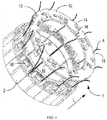
FIG. 1 is a schematic perspective view illustrating the assembly of a wiring apparatus to a motor according to an embodiment of the present disclosure; -
FIG. 2 is a schematic perspective view illustrating a wiring apparatus according to an embodiment of the present disclosure; -
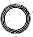
FIG. 3 is a schematic front view illustrating a wiring apparatus according to an embodiment of the present disclosure; -
FIG. 4 is a cross sectional view illustrating a part of a wiring apparatus taken along the line A-A inFIG. 3 ; -
FIG. 5 is a schematic diagram illustrating a conductor provided in a wiring apparatus according to an embodiment of the present disclosure, in which an annular member is hidden to show a configuration of the conductor; -
FIG. 6 is a schematic perspective view illustrating a state after assembling a wiring apparatus to a motor according to an embodiment of the present disclosure, in which an enameled wire of the motor and the wiring apparatus are connected by surface connection; and -
FIG. 7 is another schematic perspective view illustrating a state after assembling a wiring apparatus to a motor according to an embodiment of the present disclosure, in which an enameled wire of the motor and the wiring apparatus are connected by a perforated connection. - The principle of the present disclosure will now be described with reference to various embodiments in the drawings. It should be understood that these embodiments are only for the purpose of enabling those skilled in the art to better understand and thereby implement the present disclosure, and are not described for the purpose of placing any limitation on the scope of the present disclosure. It should be noted that similar or identical reference signs may be used in the drawings where feasible, and similar or identical reference signs may indicate similar or identical elements. Those skilled in the art will understand that alternative embodiments of the structures and methods described herein may be adopted without departing from the principles of the present disclosure described from the following description.
- As mentioned above, in the existing wiring scheme, an enameled wire and a lead wire of the winding adopt the traditional connection method, which is cumbersome and cannot be achieved automatically. In addition, the thickness of a motor winding terminal is increased, which is not conducive to heat dissipation of a motor.
- To solve the above problems, the present disclosure provides wiring apparatus with a simple structure and which is easy to realize automatic wiring.
- Implementations of embodiments of the present disclosure will be described with reference to
FIGS. 1 to 7 . - Embodiment of the present disclosure relate to a
wiring apparatus 1 for amotor 2. As shown inFIG. 1 , thewiring apparatus 1 generally comprises anannular member 10 and aconductor 20 embedded in theannular member 10. With reference toFIG. 2 , theannular member 10 is arranged near a leading-out terminal of a winding of themotor 2 and has afirst side 12 adjacent to themotor 2 and asecond side 14 opposite to thefirst side 12. -
FIG. 4 is a cross sectional view of a part of theannular member 10. As shown inFIG. 4 , theconductor 20 is embedded in theannular member 10 and is surrounded by theannular member 10. Theconductor 20 comprises aconductive bar 24 and a plurality ofjoints 22 coupled to each other via theconductive bar 24. Theannular member 10 comprises a first group ofholes 16 and a second group ofholes 18 arranged opposite to the first set ofholes 16. The first group ofholes 16 each extends from thefirst side 12 to the plurality ofjoints 22. The second group ofholes 18 each extend from thesecond side 14 to the plurality ofjoints 22. As shown inFIG. 4 , each hole in the first set ofholes 16 and each hole in the second set ofholes 18 extend from opposite sides to thecorresponding joints 22. - According to embodiments of the present disclosure, as shown in
FIG. 1 , since theconductive bar 24 connects the plurality ofjoints 22 to each other, anenameled wire 4 of themotor 2 can be coupled together in a predetermined manner through thejoints 22. In addition, theannular member 10 can be designed to have a smaller size (i.e., thickness) in a direction L substantially parallel to the axial direction of themotor 2. In this way, when thewiring apparatus 1 realizes a wiring function of themotor 2, no additional space in the direction L is required, making the structure of themotor 2 more compact. Such a configuration is beneficial in small and medium-sized servo motors. - In some embodiments, as shown in
FIG. 7 , a plurality ofenameled wires 4 of themotor 2 may extend from themotor 2 and be connected to thejoints 22 via one side of thewiring apparatus 1 close to themotor 2. Specifically, with reference toFIG. 4 , theenameled wire 4 is inserted into the corresponding first set ofholes 16 from thefirst side 12 of theannular member 10 of thewiring apparatus 1 substantially along the direction L and is coupled to thecorresponding joints 22. Since thejoints 22 are coupled to each other through theconductive bar 24, in this way, the plurality ofenameled wires 4 can be coupled to each other in a predetermined manner. Such a wiring method is called multiple parallel wiring. - In other embodiments, as shown in
FIG. 6 , the plurality of enameledwires 4 of themotor 2 may also be connected to thejoints 22 via a side of thewiring apparatus 1 away from themotor 2. Referring toFIG.2 , theannular member 10 may further comprise agroove 15 provided at the periphery thereof. Thegroove 15 extends from thefirst side 12 to thesecond side 14 for the enameledwires 4 of themotor 2 to pass through from thefirst side 12. The enameledwires 4 can thus be connected to thejoints 22 via the second set ofholes 18 on thesecond side 14. Since thejoints 22 are coupled to each other via theconductive bar 24, in this way, the plurality of enameledwires 4 can be coupled to each other in a predetermined manner. Such a wiring method is called one-way parallel wiring. - According to embodiment of the present disclosure, the enameled
wires 4 can be connected to thewiring apparatus 1 from different directions, thereby achieving a flexible wiring. In this way, users are allowed to adopt a corresponding wiring method according to a specific usage environment, and the applicability of thewiring apparatus 1 is improved. - In some embodiments, as shown in
FIG. 3 , theannular member 10 may further comprise awelding hole 13 provided at the periphery of theannular member 10. Thewelding hole 13 extends from thefirst side 12 to thesecond side 14 and is adapted for alead wire 3 of themotor 2 to pass through to be welded to thelead wire 3. -
FIGS. 6 and7 show the states where thewelding hole 13 and thelead wire 3 are welded. When assembling thelead wire 3 to thewelding hole 13, users can first approach thewiring apparatus 1 to themotor 2 and then align thelead wire 3 with thewelding hole 13 and then pass thelead wire 3 through thewelding hole 13 so as to realize the welding of thelead wire 3 and thewelding hole 13. After the welding is completed, as discussed above, users can connect the enameledwire 4 to thejoints 20 of themotor 2 either from the first set ofholes 16 on thefirst side 12 or from the second set ofholes 18 on thesecond side 12 according to the predetermined wiring method. Thelead wire 3 can be directly welded on thewiring apparatus 1 neatly and compactly so as to save the space for a leading out a wire. - In this way, with the
wiring apparatus 1, no special tools are required to realize the wiring of thelead wire 3 and the enameledwire 4. The wiring procedure is easy to complete, which greatly improves the users' working efficiency. - In some embodiments, as shown in
FIG. 2 , the welding holes 13 may comprise a plurality of welding holes 13 arranged adjacent to each other at the periphery of theannular member 10. The welding holes 13 may be provided at the periphery of theannular member 10 adjacent to each other. Although only threewelding holes 13 are shown inFIG. 2 , it is clear that users can change the number of welding holes 13 according to specific requirements, for example, two or four. The specific number is not limited by embodiments of the present invention. - In some embodiments, as shown in
FIGS. 2 and3 , thewiring apparatus 1 may further comprise aprotrusion 30 adjacent to the periphery of theannular member 10. Referring toFIG. 4 , theprotrusion 30 extends from thefirst side 12 close to themotor 2 toward themotor 2. Referring back toFIG. 1 , in an alternative embodiment, arecess 40 is provided at the periphery of the stator of themotor 2, and the position and size of therecess 40 are designed to match theprotrusion 30 to facilitate the insertion of theprotrusion 30 into therecess 40, in order to realize the connection of thewiring apparatus 1 and themotor 2. In some embodiments, therecess 40 may be provided at a terminal of a stator core insulation frame of themotor 2. In use, users can weld thelead wire 3 to thewelding hole 13 after inserting theprotrusion 30 of thewiring apparatus 1 into therecess 40 of themotor 2. - Since the
protrusions 30 are arranged at an edge of theannular member 10, the radial dimension of theannular member 10 will not be increased. In addition, the space in therecess 40 of themotor 2 is properly used for coupling with theprotrusion 30. Therefore, when thewiring apparatus 1 and themotor 2 are assembled, the size of the assembledwiring apparatus 1 and themotor 2 in the direction L will not be increased. In this way, the size of themotor 2 can be more compact and such a compact design can speed up heat dissipation from themotor 2. - In an alternative embodiment, the
wiring apparatus 1 and themotor 2 can be connected in other ways, such as a snap connection, a magnetic connection, and so on. The specific manner of connection can be adjusted according to actual needs, and is not limited by embodiments of the present disclosure. In this way, the connection of thedevice 1 and themotor 2 can be firmly connected without increasing the size of themotor 2. Therefore, the potential safety hazards caused by weak wiring can be avoided. - In some embodiments, the
conductor 20 may be made of a metal comprising copper. Copper can ensure a stable connection among thevarious joints 22 of theconductor 20. In alternative embodiments, other materials may be used in addition to copper, such as aluminum. Users can choose appropriate materials according to actual needs, such as cost considerations. The specific materials are not limited by embodiments of the present disclosure. - In some embodiments, the
annular member 10 may be made of an insulating material. The insulating material can be resin or plastic. It is to be understood that theannular member 10 can be made of materials other than the materials listed here, as long as the material can achieve an insulating effect. -
FIG. 5 shows an arrangement of theconductor 20 embedded in theannular member 10. As shown, in some embodiments, theconductive bar 24 may be spirally arranged in theannular member 10 and insulated from the outside by theannular member 10. According to different wiring requirements, the corresponding arrangement of theconductive bar 24 can be designed in advance. Users only need to connect the enameledwire 4 of themotor 20 through the first set ofholes 16 or the second set ofholes 18 of theannular member 10 to couple with thejoints 22 to complete the wiring without crimping or welding. This greatly improves the efficiency of automatic wiring. In addition, since the enameledwire 4 does not need an insulation protection such as insulation sleeves, crimp terminals, insulation tapes, etc., the cost of wiring can be reduced. - The spiral arrangement can make use of the space of the
annular member 10 to the maximal content without increasing the size of thewiring apparatus 1. - In some embodiments, the thickness and the width of the
conductive bar 24 can be adjusted according to output current and installation space of themotor 2. In some embodiments, theconductive bars 24 may be arranged along the circumferential direction of theannular member 10 according to the principle of the shortest distance and no crossing. Although the number of thejoints 22 on theconductive bar 24 is shown inFIG. 5 , it is to be understood that the number shown here is only illustrative, and the specific number is not limited by embodiments of the present disclosure. - In other embodiments, as shown in
FIG. 5 , several supportingbars 26 may be provided between the conductive bars 24. The supporting bars 26 ensure the integrity of theconductive bars 24 during the injection molding process so that theconductive bars 24 can be set in a predetermined position. In addition, the supportingbars 26 ensure relative electrical insulation distance between theconductive bars 24, thereby improving the electrical performance of the conductive bars 24. In an alternative embodiment, after the injection molding is completed, the supportingbars 26 may be removed. - Embodiments of the present disclosure relates to the
motor 2. Themotor 2 comprises thewiring apparatus 1 discussed above. Themotor 2 may be a servo motor used on an industrial robot. In an alternative embodiment, themotor 2 may be a small and medium-sized AC servo motor having concentrated windings. - According to the
wiring apparatus 1 of the present disclosure, due to its compact structure, the thickness of a leading-out terminal of the winding terminal of themotor 2 can be reduced, thereby making the design of themotor 2 more compact and reliable. In addition, the present disclosure can make the wiring of the enameledwire 4 and thelead wire 3 of themotor 2 simpler, which can realize automatic wiring to match the process flow of the production line. This is beneficial to mass production. - In spite of claims in this application drafted for specific combinations of features, it should be understood that the scope of the present disclosure also comprises any novel feature or any novel combination of features disclosed herein, explicitly or implicitly, or any generalization thereof, regardless of whether it involves the same solution in any of the claims currently claimed.
Claims (9)
- A wiring apparatus for a motor, comprising:an annular member (10) having a first side (12) adjacent to a motor (2) and a second side (14) opposite to the first side (12); anda conductor (20) embedded in the annular member (10) and comprising a plurality of joints (22) coupled to each other via a conductive bar (24);wherein the annular member (10) comprises a first group of holes (16) and a second group of holes (18), the first group of holes (16) each extending from the first side (12) to the plurality of joints (22), the second group of holes (18) arranged opposite to the first set of holes (16) and each extending from the second side (14) to the plurality of joints (22).
- The wiring apparatus of claim 1, wherein the annular member (10) further comprises:
a groove (15) arranged at a periphery of the annular member (10) and extending from the first side (12) to the second side (14), the groove (15) being adapted for an enameled wire (4) of the motor (2) to pass through from the first side (12) to enter the second set of holes (18) on the second side (14), so as to be connected to the joint (22). - The wiring apparatus of claim 1 or 2, wherein the annular member (10) further comprises:
a welding hole (13) provided at a periphery of the annular member (10) and extending from the first side (12) to the second side (14), the welding hole (13) being adapted for a lead wire (3) of the motor (2) to pass through to be welded to the lead wire (3). - The wiring apparatus of claim 3, wherein the welding hole (13) comprises a plurality of welding holes arranged adjacent to each other at the periphery of the annular member (10).
- The wiring apparatus of any of the preceding claims, further comprising:
a protrusion (30) adjacent to a periphery of the annular member (10) and extending from the first side (12) toward the motor (2) so as to be inserted into a recess (40) of the periphery of a stator of the motor (2). - The wiring apparatus of any of the preceding claims, wherein the conductor (20) is made of a metal comprising copper.
- The wiring apparatus of any of the preceding claims, wherein the annular member (10) is made of an insulating material.
- The wiring apparatus of any of the preceding claims, wherein the conductive bar (24) is helically arranged in the annular member (10) and is insulated from outside by the annular member (10).
- A motor at least comprising a wiring apparatus (1) of any one of claims 1 to 8.
Applications Claiming Priority (1)
| Application Number | Priority Date | Filing Date | Title |
|---|---|---|---|
| CN202010188022.0A CN111224493B (en) | 2020-03-17 | 2020-03-17 | Wiring device for an electric machine and corresponding electric machine |
Publications (1)
| Publication Number | Publication Date |
|---|---|
| EP3883098A1 true EP3883098A1 (en) | 2021-09-22 |
Family
ID=70828436
Family Applications (1)
| Application Number | Title | Priority Date | Filing Date |
|---|---|---|---|
| EP21160507.6A Pending EP3883098A1 (en) | 2020-03-17 | 2021-03-03 | Wiring apparatus for motor and corresponding motor |
Country Status (4)
| Country | Link |
|---|---|
| US (1) | US11682941B2 (en) |
| EP (1) | EP3883098A1 (en) |
| CN (1) | CN111224493B (en) |
| MX (1) | MX2021002684A (en) |
Families Citing this family (2)
| Publication number | Priority date | Publication date | Assignee | Title |
|---|---|---|---|---|
| CN112953073B (en) * | 2021-01-28 | 2021-10-08 | 浙江方正电机股份有限公司 | End integrated module of flat copper wire oil-cooled motor stator and stator |
| CN121153187A (en) * | 2023-05-25 | 2025-12-16 | 松下知识产权经营株式会社 | motor |
Citations (7)
| Publication number | Priority date | Publication date | Assignee | Title |
|---|---|---|---|---|
| US4689023A (en) * | 1985-08-27 | 1987-08-25 | The Superior Electric Company | Programmable electrical connector |
| US20030086800A1 (en) * | 2001-11-08 | 2003-05-08 | Tadashi Kurihara | Motor-driven compressors |
| US20140183992A1 (en) * | 2012-12-27 | 2014-07-03 | Samsung Electro-Mechanics Co., Ltd | Motor and manufacturing method thereof |
| CN105119411A (en) | 2015-09-10 | 2015-12-02 | 安徽巨一自动化装备有限公司 | AC motor stator winding wiring ring connection structure |
| CN206878589U (en) * | 2017-06-29 | 2018-01-12 | 广东威灵电机制造有限公司 | Termination and stator |
| DE112016003656T5 (en) * | 2015-08-10 | 2018-05-09 | Nidec Corporation | ENGINE |
| FR3071112A1 (en) * | 2017-09-12 | 2019-03-15 | Mmt ag | CONNECTION SYSTEM FOR ELECTRIC MACHINE. |
Family Cites Families (14)
| Publication number | Priority date | Publication date | Assignee | Title |
|---|---|---|---|---|
| JPH07284239A (en) * | 1994-04-11 | 1995-10-27 | Fujitsu General Ltd | Electric motor |
| CN1235325C (en) * | 2002-06-07 | 2006-01-04 | 多摩川精机株式会社 | Stator structure having printed circuit board |
| JP2004048950A (en) * | 2002-07-15 | 2004-02-12 | Matsushita Electric Ind Co Ltd | Permanent magnet type motor |
| DE10261611A1 (en) | 2002-12-27 | 2004-07-08 | Robert Bosch Gmbh | Connection element for a winding of an electrical machine |
| WO2004114502A1 (en) * | 2003-06-20 | 2004-12-29 | Siemens Aktiengesellschaft | Electric machine comprising a circuit support |
| CN202309300U (en) | 2011-10-11 | 2012-07-04 | 杭州米格电机有限公司 | Wiring device of motor stator winding |
| CN202550819U (en) * | 2012-02-03 | 2012-11-21 | 倪正尧 | Circuit board for motor stator winding wiring |
| CA2899382A1 (en) * | 2013-02-07 | 2014-08-14 | Furukawa Electric Co., Ltd. | Enamel resin-insulating laminate, insulated wire using the same and electric/electronic equipment |
| CN104852498A (en) * | 2015-04-21 | 2015-08-19 | 李龙 | Winding end patch board of concentrated winding motor |
| FR3043150B1 (en) * | 2015-10-29 | 2019-10-11 | Valeo Systemes Thermiques | FAN MOTOR ASSEMBLY AND HEATING, VENTILATION AND / OR AIR CONDITIONING SYSTEM FOR A CORRESPONDING MOTOR VEHICLE |
| KR102553437B1 (en) * | 2018-03-12 | 2023-07-11 | 에섹스 후루카와 마그넷 와이어 재팬 가부시키가이샤 | Collecting conductors, split conductors, segment coils and motors using them |
| CN208955778U (en) * | 2018-09-17 | 2019-06-07 | 佛山登奇机电技术有限公司 | A kind of motor Wiring circuit board |
| DE102019107529B4 (en) * | 2019-03-25 | 2024-12-12 | Hanon Systems | Device for driving a compressor and method for assembling the device |
| CN110011456A (en) | 2019-05-12 | 2019-07-12 | 苏州新智机电工业有限公司 | A block type stator winding end wiring structure |
-
2020
- 2020-03-17 CN CN202010188022.0A patent/CN111224493B/en active Active
-
2021
- 2021-03-02 US US17/189,420 patent/US11682941B2/en active Active
- 2021-03-03 EP EP21160507.6A patent/EP3883098A1/en active Pending
- 2021-03-05 MX MX2021002684A patent/MX2021002684A/en unknown
Patent Citations (7)
| Publication number | Priority date | Publication date | Assignee | Title |
|---|---|---|---|---|
| US4689023A (en) * | 1985-08-27 | 1987-08-25 | The Superior Electric Company | Programmable electrical connector |
| US20030086800A1 (en) * | 2001-11-08 | 2003-05-08 | Tadashi Kurihara | Motor-driven compressors |
| US20140183992A1 (en) * | 2012-12-27 | 2014-07-03 | Samsung Electro-Mechanics Co., Ltd | Motor and manufacturing method thereof |
| DE112016003656T5 (en) * | 2015-08-10 | 2018-05-09 | Nidec Corporation | ENGINE |
| CN105119411A (en) | 2015-09-10 | 2015-12-02 | 安徽巨一自动化装备有限公司 | AC motor stator winding wiring ring connection structure |
| CN206878589U (en) * | 2017-06-29 | 2018-01-12 | 广东威灵电机制造有限公司 | Termination and stator |
| FR3071112A1 (en) * | 2017-09-12 | 2019-03-15 | Mmt ag | CONNECTION SYSTEM FOR ELECTRIC MACHINE. |
Also Published As
| Publication number | Publication date |
|---|---|
| MX2021002684A (en) | 2021-09-20 |
| US11682941B2 (en) | 2023-06-20 |
| US20210296958A1 (en) | 2021-09-23 |
| CN111224493A (en) | 2020-06-02 |
| CN111224493B (en) | 2022-07-29 |
Similar Documents
| Publication | Publication Date | Title |
|---|---|---|
| US6914356B2 (en) | Rotating electric machine and method for manufacturing the same | |
| CN100386948C (en) | Collecting and distributing ring for stator of rotating electric machine | |
| CN101227117B (en) | Insulation case for motors | |
| US5508571A (en) | Neutral connection for wire wound stator | |
| US20040119350A1 (en) | Resolver I/O terminal structure and method of connecting resolver thereby | |
| US20110018376A1 (en) | Busbar terminal, busbar unit, and motor | |
| CN112186934B (en) | Bus bar of flat wire motor and flat wire motor | |
| JP2014007829A (en) | Stator and manufacturing method therefor | |
| CN110474461B (en) | Motor stator and manufacturing method thereof | |
| US11682941B2 (en) | Wiring apparatus for motor and corresponding motor | |
| US5268604A (en) | Armature of a small motor employing an insulating holder having a plurality of sections | |
| CN205544819U (en) | Collecting ring and concentrated winding formula motor | |
| JP2009536512A (en) | Method of manufacturing rotor of rotating electrical device and rotor of rotating electrical device | |
| CN110611389B (en) | Electronically commutated motors | |
| CN206742993U (en) | Motor and its stator insulation component | |
| CN112531947B (en) | A modular end winding connection structure for an electric motor | |
| JP2006174547A (en) | Rotating electric machine stator | |
| CN107508391A (en) | Brshless DC motor, stator component and its method for winding | |
| CN223680850U (en) | Wire connecting plate | |
| CN115967211A (en) | Motor stator and motor | |
| JPH04317534A (en) | Brushless motor | |
| CN223680849U (en) | junction box | |
| CN219918550U (en) | Stator structure of external rotor motor | |
| JP2007028824A (en) | Commutator and armature | |
| CN219394520U (en) | Motor stator |
Legal Events
| Date | Code | Title | Description |
|---|---|---|---|
| PUAI | Public reference made under article 153(3) epc to a published international application that has entered the european phase |
Free format text: ORIGINAL CODE: 0009012 |
|
| STAA | Information on the status of an ep patent application or granted ep patent |
Free format text: STATUS: REQUEST FOR EXAMINATION WAS MADE |
|
| 17P | Request for examination filed |
Effective date: 20210303 |
|
| AK | Designated contracting states |
Kind code of ref document: A1 Designated state(s): AL AT BE BG CH CY CZ DE DK EE ES FI FR GB GR HR HU IE IS IT LI LT LU LV MC MK MT NL NO PL PT RO RS SE SI SK SM TR |
|
| RBV | Designated contracting states (corrected) |
Designated state(s): AL AT BE BG CH CY CZ DE DK EE ES FI FR GB GR HR HU IE IS IT LI LT LU LV MC MK MT NL NO PL PT RO RS SE SI SK SM TR |
|
| STAA | Information on the status of an ep patent application or granted ep patent |
Free format text: STATUS: EXAMINATION IS IN PROGRESS |
|
| 17Q | First examination report despatched |
Effective date: 20230612 |