EP3882893A1 - A target vehicle for adas testing - Google Patents
A target vehicle for adas testing Download PDFInfo
- Publication number
- EP3882893A1 EP3882893A1 EP21163287.2A EP21163287A EP3882893A1 EP 3882893 A1 EP3882893 A1 EP 3882893A1 EP 21163287 A EP21163287 A EP 21163287A EP 3882893 A1 EP3882893 A1 EP 3882893A1
- Authority
- EP
- European Patent Office
- Prior art keywords
- target vehicle
- sensor
- target
- assembly
- tilt
- Prior art date
- Legal status (The legal status is an assumption and is not a legal conclusion. Google has not performed a legal analysis and makes no representation as to the accuracy of the status listed.)
- Granted
Links
Images


Classifications
-
- B—PERFORMING OPERATIONS; TRANSPORTING
- B60—VEHICLES IN GENERAL
- B60W—CONJOINT CONTROL OF VEHICLE SUB-UNITS OF DIFFERENT TYPE OR DIFFERENT FUNCTION; CONTROL SYSTEMS SPECIALLY ADAPTED FOR HYBRID VEHICLES; ROAD VEHICLE DRIVE CONTROL SYSTEMS FOR PURPOSES NOT RELATED TO THE CONTROL OF A PARTICULAR SUB-UNIT
- B60W50/00—Details of control systems for road vehicle drive control not related to the control of a particular sub-unit, e.g. process diagnostic or vehicle driver interfaces
- B60W50/04—Monitoring the functioning of the control system
- B60W50/045—Monitoring control system parameters
-
- G—PHYSICS
- G09—EDUCATION; CRYPTOGRAPHY; DISPLAY; ADVERTISING; SEALS
- G09B—EDUCATIONAL OR DEMONSTRATION APPLIANCES; APPLIANCES FOR TEACHING, OR COMMUNICATING WITH, THE BLIND, DEAF OR MUTE; MODELS; PLANETARIA; GLOBES; MAPS; DIAGRAMS
- G09B9/00—Simulators for teaching or training purposes
- G09B9/02—Simulators for teaching or training purposes for teaching control of vehicles or other craft
- G09B9/04—Simulators for teaching or training purposes for teaching control of vehicles or other craft for teaching control of land vehicles
- G09B9/058—Simulators for teaching or training purposes for teaching control of vehicles or other craft for teaching control of land vehicles for teaching control of cycles or motorcycles
-
- G—PHYSICS
- G01—MEASURING; TESTING
- G01M—TESTING STATIC OR DYNAMIC BALANCE OF MACHINES OR STRUCTURES; TESTING OF STRUCTURES OR APPARATUS, NOT OTHERWISE PROVIDED FOR
- G01M17/00—Testing of vehicles
- G01M17/007—Wheeled or endless-tracked vehicles
- G01M17/0072—Wheeled or endless-tracked vehicles the wheels of the vehicle co-operating with rotatable rolls
- G01M17/0076—Two-wheeled vehicles
-
- G—PHYSICS
- G01—MEASURING; TESTING
- G01M—TESTING STATIC OR DYNAMIC BALANCE OF MACHINES OR STRUCTURES; TESTING OF STRUCTURES OR APPARATUS, NOT OTHERWISE PROVIDED FOR
- G01M17/00—Testing of vehicles
- G01M17/007—Wheeled or endless-tracked vehicles
-
- B—PERFORMING OPERATIONS; TRANSPORTING
- B60—VEHICLES IN GENERAL
- B60W—CONJOINT CONTROL OF VEHICLE SUB-UNITS OF DIFFERENT TYPE OR DIFFERENT FUNCTION; CONTROL SYSTEMS SPECIALLY ADAPTED FOR HYBRID VEHICLES; ROAD VEHICLE DRIVE CONTROL SYSTEMS FOR PURPOSES NOT RELATED TO THE CONTROL OF A PARTICULAR SUB-UNIT
- B60W40/00—Estimation or calculation of non-directly measurable driving parameters for road vehicle drive control systems not related to the control of a particular sub unit, e.g. by using mathematical models
- B60W40/12—Estimation or calculation of non-directly measurable driving parameters for road vehicle drive control systems not related to the control of a particular sub unit, e.g. by using mathematical models related to parameters of the vehicle itself, e.g. tyre models
-
- G—PHYSICS
- G01—MEASURING; TESTING
- G01M—TESTING STATIC OR DYNAMIC BALANCE OF MACHINES OR STRUCTURES; TESTING OF STRUCTURES OR APPARATUS, NOT OTHERWISE PROVIDED FOR
- G01M17/00—Testing of vehicles
-
- G—PHYSICS
- G01—MEASURING; TESTING
- G01M—TESTING STATIC OR DYNAMIC BALANCE OF MACHINES OR STRUCTURES; TESTING OF STRUCTURES OR APPARATUS, NOT OTHERWISE PROVIDED FOR
- G01M17/00—Testing of vehicles
- G01M17/007—Wheeled or endless-tracked vehicles
- G01M17/06—Steering behaviour; Rolling behaviour
-
- B—PERFORMING OPERATIONS; TRANSPORTING
- B60—VEHICLES IN GENERAL
- B60W—CONJOINT CONTROL OF VEHICLE SUB-UNITS OF DIFFERENT TYPE OR DIFFERENT FUNCTION; CONTROL SYSTEMS SPECIALLY ADAPTED FOR HYBRID VEHICLES; ROAD VEHICLE DRIVE CONTROL SYSTEMS FOR PURPOSES NOT RELATED TO THE CONTROL OF A PARTICULAR SUB-UNIT
- B60W50/00—Details of control systems for road vehicle drive control not related to the control of a particular sub-unit, e.g. process diagnostic or vehicle driver interfaces
- B60W2050/0001—Details of the control system
- B60W2050/0019—Control system elements or transfer functions
- B60W2050/0028—Mathematical models, e.g. for simulation
- B60W2050/0031—Mathematical model of the vehicle
- B60W2050/0033—Single-track, 2D vehicle model, i.e. two-wheel bicycle model
-
- B—PERFORMING OPERATIONS; TRANSPORTING
- B60—VEHICLES IN GENERAL
- B60W—CONJOINT CONTROL OF VEHICLE SUB-UNITS OF DIFFERENT TYPE OR DIFFERENT FUNCTION; CONTROL SYSTEMS SPECIALLY ADAPTED FOR HYBRID VEHICLES; ROAD VEHICLE DRIVE CONTROL SYSTEMS FOR PURPOSES NOT RELATED TO THE CONTROL OF A PARTICULAR SUB-UNIT
- B60W2520/00—Input parameters relating to overall vehicle dynamics
- B60W2520/12—Lateral speed
- B60W2520/125—Lateral acceleration
Definitions
- a target assembly also sometimes known as a Guided Soft Target (GST)
- GST Guided Soft Target
- the testing platform typically follows a predetermined path (dependent on the scenario being modelled).
- the testing platform carries a target vehicle that replicates the appearance of a road vehicle, but is made of a soft material to minimise any damage to the vehicle being tested in the event of a collision.
- VRUs Vulnerable Road Users
- the senor is also be used for other purposes.
- the sensor may be a sensor that is used for controlling of the platform.
- the target assembly comprising a testing platform and a target vehicle mounted thereon, the target assembly comprising (a) a sensor arranged to measure a parameter relating to the dynamics of the target assembly, and (b) an actuation assembly arranged to adjust the tilt of the target vehicle in dependence on the output of the sensor.
- the present invention provides a target vehicle for mounting onto an ADAS testing platform.
- the target vehicle comprises: a sensor arranged to measure a parameter relating to the dynamics of the target vehicle; and an actuation assembly arranged to adjust the tilt of the target vehicle in dependence on the output of the sensor. It has been recognised that by measuring the parameter relating to the dynamics of the target vehicle, the tilt of the vehicle may be adjusted to more accurately model the real-world behaviour of such a vehicle.
- a measurement of the parameter relating to the dynamics of the vehicle may be obtainable from a sensor in the testing platform (a testing platform typically already has a plurality of sensors from which this measurement may be derived).
- preferred embodiments of the invention recognise that by providing a sensor on the target vehicle, the target vehicle may then be configured to provide this functionality independently of the testing platform.
- the testing vehicle may be largely self-contained and may be arranged to tilt during cornering regardless of the platform on which it is mounted. Such an arrangement is beneficial because it avoids the need for communication or other interfacing between the testing platform and the target vehicle.
- the target vehicle of the second aspect is suitable for mounting onto an ADAS testing platform, but does not include the testing platform itself.
- the target vehicle may be remote from a testing platform.
- the sensor and the actuation assembly may be arranged to function independently of the testing platform onto which the target vehicle may be mounted.
- the sensor is not part of the testing platform.
- the target vehicle may comprise feet for detachably mounting to the testing platform.
- the target vehicle may comprise no means of self-propulsion.
- the target vehicle is, for example, a model with no means of its own propulsion.
- the simulation tilt angle is preferably variable and not a fixed value.
- the simulation tilt angle may be the tilt angle suitable for modelling the real-world tilt that would be experienced by the target vehicle.
- the simulation tilt angle may, at any one time, therefore depend on, for example, the radius of the turn and the speed at which the target vehicle is travelling.
- the simulation tilt angle may be a target angle.
- the tilt angle will be understood to be the angle at which the target vehicle tilts away from the absolute vertical (i.e. the direction in which gravity acts). This may also be referred to as the lean angle.
- the angle is typically measured between the absolute vertical direction and the plane in which the diameter of the target vehicle's wheels lie.
- Embodiments of the present invention seek to replicate the real-word tilt angle as closely as possible.
- the rider When riding a two-wheeled vehicle such as a motorbike, the rider naturally seeks to adjust the centre of mass (of the bike and rider) to counteract other forces that may otherwise create an overturning moment. These forces may be due to a number of factors such as the slope/camber of the surface being traversed, or external forces such as the wind.
- a common scenario encountered is during cornering of a two-wheeled vehicle such as a motorbike, where the rider naturally seeks to adjust the centre of mass (of the bike and rider) to counteract the overturning moment exerted on the target vehicle during movement around the corner.
- the simulation tilt angle is the tilt angle necessary to counteract the overturning moment exerted on the target vehicle.
- the simulation tilt angle may be the tilt angle necessary to counteract the overturning moment exerted on the target vehicle during movement of the platform around a corner.
- Such an arrangement may closely replicate the tilt experienced by a rider performing such a manoeuvre in the real-world.
- the target vehicle tends to be responsive to whatever conditions the platform encounters (such as adjusting for road surface changes that may impact on the forces experienced by the target vehicle).
- the target vehicle may comprise a base for mounting in a fixed position relative to the platform, and a tiltable body for tilting relative to the base.
- the target vehicle may comprise a hinge having a hinge axis about which the tiltable portion may rotate.
- the hinge axis is preferably located such that the hinge axis is proximate the contact patch between the target vehicle's wheels and the ground.
- the hinge axis may be proximate the platform.
- the platform is typically low-profile, such that the axis is also proximate the contact patch. Keeping the hinge axis close to the testing platform, seeks to ensure the target vehicle tilts about, or near, the contact patch, and therefore seeks to model the real-world scenario.
- the sensor is preferably located on the tiltable body such that the sensor moves during tilting of the target vehicle.
- Such an arrangement is beneficial because the sensor tends to measure the parameter as it would be experienced on the vehicle when tilted. This tends to ensure a realistic tilt angle is achieved because it allows the target vehicle to be responsive to whatever conditions the tiltable part of the vehicle is encountering.
- the sensor may be an accelerometer.
- the parameter relating to the dynamics of the target vehicle may be an acceleration.
- the accelerometer may be arranged to measure lateral acceleration of the target vehicle.
- the lateral acceleration is the acceleration in the lateral direction.
- the lateral direction is preferably the lateral direction in the frame of reference of the target vehicle. In the frame of reference of the target vehicle, the lateral direction is perpendicular to the vertical direction when the target vehicle is upright.
- the lateral direction is preferably horizontal when the target vehicle is upright, but the lateral direction may be inclined (from the horizontal) by the tilt angle when the target vehicle is tilted.
- An accelerometer may also be relatively precise, relative to some other sensors such as spatial sensors (for example a GPS sensor).
- the control unit may be arranged to adjust the tilt in a manner that seeks to keep the measured lateral acceleration at or below a threshold value.
- the control unit may be arranged to adjust the tilt in a manner that seeks to keep the measured lateral acceleration at a minimum value.
- Minimal lateral acceleration (for example substantively zero lateral acceleration) is obtained when the resultant force is directed through the hinge axis. This resultant force may be directed through the plane of the wheels. This is also the tilt that a rider of the vehicle would naturally tend to adopt in the real-world scenario.
- the actuation assembly may comprise a rotary actuator. Rotation of the rotary actuator preferably effects the tilt of the target vehicle.
- a rotary actuator has been found to facilitate a relatively compact actuator assembly, for example enabling the actuator assembly to be mounted inside the target. This tends to be especially beneficial for a target vehicle because it enables the overall shape/radar signature, of the target vehicle to closely match a corresponding real world vehicle (and therefore ensure accurate ADAS testing).
- the actuation assembly may comprise a pinion engaged with a rack.
- the pinion may be arranged to be driven by the actuator such that rotation of the pinion moves the pinion along the rack to tilt the target vehicle.
- the rack may be attached to a base portion of the target vehicle.
- the rack may be a toothed belt.
- a belt may be beneficial because it tends not to be readily damaged in collisions.
- a belt may be beneficial because it is readily attachable/detachable from a base portion of the target vehicle.
- a two-wheeled target vehicle for mounting onto an ADAS testing platform, the target vehicle being arranged to simulate the tilting of a two-wheeled vehicle during cornering, wherein the target vehicle comprises: a sensor arranged to measure a parameter of the target vehicle dynamics as it is moved by the testing platform; an actuation assembly arranged to adjust the tilt of the target vehicle; a control unit configured to control the actuation assembly to adopt a simulation tilt angle, the magnitude of the simulation tilt angle being dependent on the output of the sensor, wherein the sensor, control unit and actuator assembly are self-contained within the target vehicle and are independent of the platform to which the target vehicle is mounted.
- a target assembly comprising a testing platform onto which the target vehicle of the above-mentioned aspects is mounted.
- an assembly for tilting a target vehicle comprising: a sensor for attaching to a target vehicle to measure a parameter relating to the dynamics of the target vehicle; an actuation assembly arranged to adjust the tilt of the target vehicle in dependence on the output of the sensor; and a control unit configured to control the actuation assembly to adopt a simulation tilt angle, the magnitude of the simulation tilt angle being dependent on the output of the sensor.
- a method of modelling a VRU for ADAS testing using a target vehicle mounted on a moveable testing platform comprising the steps of: measuring a parameter relating to the dynamics of the target vehicle; and adjusting the tilt of the target vehicle in dependence on the output of the sensor, wherein the steps of measuring and adjusting are conducted remotely from the testing platform.
- the steps of measuring and adjusting preferably all take place in the target vehicle.
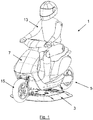
- FIG. 1 is a perspective view of a target assembly (also referred to as a guided soft target (GST)) 1.
- the GST 1 comprises a low-profile testing platform 3 onto which is mounted a target vehicle 5 according to a first embodiment of the invention.
- the target vehicle 5 is seeking to replicate a moped, which is a type of target often referred to as a vulnerable road user (VRU).
- the target vehicle 5 comprises a sacrificial soft, body 7 (made from close cell polyethylene foam) that closely resembles a real-world moped.
- the soft body 7 encloses a framework 9 and tilting assembly 11 (discussed in more detail in Figures 4 to 6 below).
- a dummy-rider 13 is sat on the target vehicle 5.
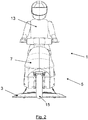
- Figures 2 and 3 show the GST 1 in frontal view during two different scenarios.
- the testing platform 3 is traversing level ground in a straight line. The moped is therefore upright, with its centre of mass above the wheels 15.
- the testing platform 3 is on the same level ground but is traversing a curved path, for example around a corner in a road.
- the target vehicle 5 is configured so that it tilts (i.e. leans over from the upright direction) as the testing platform 3 traverses the curved path. This ensures the target vehicle 5 closely replicates the real-world movement the moped would exhibit.
- FIG. 4 this illustrates the structure of the target vehicle 5 beneath the soft body 7.
- the structure comprises a framework of tubing 9 onto which the soft body 7 (not shown in Figures 4 to 6 ) would be attached.
- the tubing connects with front and back wheels 15a, 15b.
- the structure comprises a base portion 17 having four magnetic fasteners 19 for mounting the target vehicle 5 onto the testing platform 3.
- the magnetic fasteners 19 allow the target vehicle 5 to readily detach from the testing platform 3 in the event of a collision during ADAS testing.
- a hinge axis 21 passes through two co-axial hinges 23, positioned low down on the target vehicle 5, and connecting the base portion 17 to the framework of tubing 9 above.
- the framework 9 above the base portion 17 is tiltable about the hinges 23 under the action of a tilting assembly 25.
- the tilting assembly 25 comprises an actuator 27, two accelerometers 29 and a control unit 31 (see Figures 5-7 ).
- the accelerometers 29 and the control unit 31 are located in a housing attached to the framework 9.
- the accelerometers 29 are shown schematically in Figures 5 and 6 . They are mounted on the frame 9 such that when the target vehicle is upright, the accelerometers lie along the vertical axis in the absolute frame (Z) and the local frame (Zc) relative to the target vehicle.
- the accelerometers may be in a location off from the vertical axis, and the control unit is arranged to compensate for that offset when processing the output from the accelerometers.
- Each accelerometer 29 is arranged to measure lateral acceleration a_Xc, i.e. acceleration along the lateral direction Xc relative to the target vehicle 5.
- Two accelerometers are provided to average out any noise in the signal and to average out any offset between the two sensors.
- the output of the accelerometers 29 is fed to the control unit 31. If the testing platform 3 begins to traverse a curved path, the accelerometers 29 will begin to experience an increase in lateral acceleration a_Xc.
- the control unit 31 is arranged to control the rotary actuator 27 to adjust the tilt of the testing vehicle 5 (i.e. the tilt of the tiltable framework 9 of the testing vehicle 5), such that the lateral acceleration a_Xc is minimised.
- the control unit 31 carries out the control process shown in Figure 7 to which reference is now made.
- the control unit 31 receives the signals from the accelerometers (via a Kalman filter 35 to reduce signal noise).
- the control unit 31 also receives a target lateral acceleration threshold of 0g.
- a PID controller 37 receives a measure of the difference between this target value and the measured values from the sensors 29.
- the PID 37 provides an output signal, indicative of maintaining the target threshold lateral acceleration of Og, and this output signal is sent to the actuator 27 to adjust the tilt in a manner that reduces the lateral acceleration a_Xc to the threshold value.
- the control unit 31 thus contains a control loop that seeks to maintain a simulation tilt angle ⁇ of the target vehicle at a value then results in no lateral acceleration being measured by the accelerometers 29.
- control unit 31 also contains an intermediate actuator-protection module 38 for protecting the actuator 27 from excessive electrical currents, although it will be appreciated that this protection module 38 is optional and may not necessarily be required in other embodiments.
- control unit 31 also comprises an end-stop control module 39 which is arranged to prevent the actuator assembly 27 driving beyond its end-stop positions. Again, it will be appreciated that this end-stop control module 39 is optional and may not necessarily be required in other embodiments of the invention.
- FIGS. 5 and 6 these illustrate the accelerometers 29 and other parts of the target vehicle 5 in upright and tilted configurations respectively.
- the lateral acceleration is minimised when the resultant force Rf from cornering and from gravity, is directed along the local vertical axis Zc of the target vehicle (which is the same as the direction through the plane of the wheels).
- This is the tilt angle ⁇ necessary to counteract the overturning moment exerted on the target vehicle during movement of the platform 3 around the corner, and is therefore an accurate representation of the actual tilt a rider tends to adopt when cornering a moped.
- the tilt angle ⁇ (also referred to as the lean angle) is measured between the vertical axis Zc of the vehicle and the vertical axis Z in the absolute reference frame.
- Figures 8 and 9 illustrate the actuation assembly 25 in more detail and is a section view along A-A of Figure 4 .
- the assembly 25 comprises the rotary actuator 27 orientated along the lower part of the frame, and generally along the fore-aft direction (Yc) of the testing vehicle 5.
- Yc fore-aft direction
- the use of a rotary actuator 27 and its orientation in this manner facilitates a relatively compact arrangement that does not need to protrude from the soft body 7.
- a pinion gear 43 is mounted to the output shaft of the rotary actuator 27.
- the pinion gears 43 mesh with a rack in the form of a toothed belt 45.
- the toothed belt 45 is fastened at either end 45a, 45b, to the base portion 17 of the target vehicle 5 and runs through idler gears 46 mounted on lateral arms 48.
- the pinion 43 is rotated, thereby drawing the pinion and the remainder of the tiltable part 9 of the target vehicle 5 along the toothed belt 45 in the direction and magnitude specified by the control unit 31, such that it tilts about the hinge axis 21 of the hinges 23.
- the first embodiment of the invention provides several advantages over known VRU target vehicles. Firstly, the equipment necessary to achieve the tilting of the target vehicle is self-contained on the target vehicle. It is independent of the platform on which it is mounted. This enables the target vehicle to be readily used on various different platforms and avoids the need for communication or other interfacing between the platform and testing vehicle. Secondly, the arrangement used in this embodiment of the invention has been found to provide especially realistic tilt behaviour because it measures a real-time parameter that is indicative of the tilt a rider would adopt (i.e. it measures a parameter relating to the dynamics of the vehicle (the lateral acceleration) as it is experienced by the tilting part of the target vehicle). Finally, the actuator assembly in the first embodiment is compact and has a relatively low radar signature outside the soft body of the moped; it is therefore especially beneficial for ADAS testing.
- the target vehicle may include a GPS sensor for measuring the spatial movement of the target vehicle. From that measurement of spatial movement, for example from a measurement of the yaw of the target vehicle, the appropriate tilt behaviour may be calculated and the actuator assembly instructed accordingly.
- the target vehicle may be modelling a different single-track VRU such as a push bike (bicycle) or a differently shaped motorbike.
- the senor may be a pre-existing sensor on the testing platform that was already used for controlling the testing platform (e.g. a GPS sensor).
- a communications module is provided for relaying the output of the sensor and/or the control unit, to the actuation assembly on the target vehicle, to provide a tiling actuation signal.
Landscapes
- Engineering & Computer Science (AREA)
- Physics & Mathematics (AREA)
- General Physics & Mathematics (AREA)
- Automation & Control Theory (AREA)
- Theoretical Computer Science (AREA)
- Transportation (AREA)
- Mechanical Engineering (AREA)
- Business, Economics & Management (AREA)
- Educational Administration (AREA)
- Educational Technology (AREA)
- Aviation & Aerospace Engineering (AREA)
- Human Computer Interaction (AREA)
- Mathematical Physics (AREA)
- Motorcycle And Bicycle Frame (AREA)
- Testing Of Devices, Machine Parts, Or Other Structures Thereof (AREA)
- Control Of Driving Devices And Active Controlling Of Vehicle (AREA)
Abstract
Description
- The present invention concerns targets for use in Advanced Driver Assistance Systems (ADAS) testing. More particularly, but not exclusively, this invention concerns a target vehicle for use on an ADAS testing platform, and to methods of tilting such a target vehicle.
- Many modern vehicles now include Advanced Driver Assistance Systems (ADAS). To test ADAS in vehicles, it is desirable to replicate real-world scenarios in a consistently repeatable manner, and to measure how the ADAS reacts.
- To replicate these real-world scenarios, it is known to use a target assembly (also sometimes known as a Guided Soft Target (GST)) comprising a low-profile testing platform onto which a target vehicle is mounted. The testing platform typically follows a predetermined path (dependent on the scenario being modelled). The testing platform carries a target vehicle that replicates the appearance of a road vehicle, but is made of a soft material to minimise any damage to the vehicle being tested in the event of a collision.
- As well as modelling road vehicles such as cars, it is also necessary to model what are often known as a Vulnerable Road Users (VRUs). VRUs typically include pedestrians, cyclists and motorcyclists.
- In the real-world scenario, cyclists, motorcyclists and other single track vehicles, tend to experience relatively complex dynamics, especially during cornering. In particular, such VRUs tend to need to tilt over (i.e. lean), when cornering. It is desirable to replicate this real-world scenario as accurately as possible.
- According to a first aspect of the invention, there is provided a target assembly comprising a testing platform and a target vehicle mounted thereon. The target assembly comprises: a sensor arranged to measure a parameter relating to the dynamics of the target assembly; and an actuation assembly arranged to adjust the tilt of the target vehicle in dependence on the output of the sensor. By providing a sensor to sense the dynamics of the target assembly, the target vehicle may be tilted in dependence on those dynamics. In some embodiments of the invention, the sensor is in the testing platform. In these embodiments, the target assembly may comprise a communication module for communicating signals between the platform and the target vehicle. The signals communicated by the communications module may comprise signals for actuating the actuation assembly of the target vehicle. In embodiments in which the sensor is in the testing platform, the sensor is also be used for other purposes. For example, the sensor may be a sensor that is used for controlling of the platform. Such an arrangement may be beneficial because it recognises that the output of a sensor (for example a pre-existing sensor in the testing platform) may also be used when effecting the tilt of the target vehicle. In embodiments, there is provided a target assembly comprising a testing platform and a target vehicle mounted thereon, the target assembly comprising (a) a sensor arranged to measure a parameter relating to the dynamics of the target assembly, and (b) an actuation assembly arranged to adjust the tilt of the target vehicle in dependence on the output of the sensor.
- According to a second aspect, the present invention provides a target vehicle for mounting onto an ADAS testing platform. The target vehicle comprises: a sensor arranged to measure a parameter relating to the dynamics of the target vehicle; and an actuation assembly arranged to adjust the tilt of the target vehicle in dependence on the output of the sensor. It has been recognised that by measuring the parameter relating to the dynamics of the target vehicle, the tilt of the vehicle may be adjusted to more accurately model the real-world behaviour of such a vehicle. In some embodiments, such a measurement of the parameter relating to the dynamics of the vehicle may be obtainable from a sensor in the testing platform (a testing platform typically already has a plurality of sensors from which this measurement may be derived). However, preferred embodiments of the invention, recognise that by providing a sensor on the target vehicle, the target vehicle may then be configured to provide this functionality independently of the testing platform. In other words, the testing vehicle may be largely self-contained and may be arranged to tilt during cornering regardless of the platform on which it is mounted. Such an arrangement is beneficial because it avoids the need for communication or other interfacing between the testing platform and the target vehicle.
- The target vehicle may be a Vulnerable Road User (VRU) target vehicle. The target vehicle may be replicating a single track vehicle, preferably a two-wheeled vehicle. The target vehicle may be replicating a bicycle or a motorbike.
- The target vehicle of the second aspect is suitable for mounting onto an ADAS testing platform, but does not include the testing platform itself. The target vehicle may be remote from a testing platform. The sensor and the actuation assembly may be arranged to function independently of the testing platform onto which the target vehicle may be mounted. The sensor is not part of the testing platform. The target vehicle may comprise feet for detachably mounting to the testing platform. The target vehicle may comprise no means of self-propulsion. The target vehicle is, for example, a model with no means of its own propulsion.
- The target vehicle may further comprise a control unit configured to control the actuation assembly. The control unit may be configured to adopt a simulation tilt angle. The magnitude of the simulation tilt angle may be dependent on the output of the sensor. Providing a control unit on the target vehicle, further ensures the functionality of the target vehicle is self-contained and may be independent of the testing platform.
- It will be appreciated that that the value of the simulation tilt angle is preferably variable and not a fixed value. The simulation tilt angle may be the tilt angle suitable for modelling the real-world tilt that would be experienced by the target vehicle. The simulation tilt angle may, at any one time, therefore depend on, for example, the radius of the turn and the speed at which the target vehicle is travelling. The simulation tilt angle may be a target angle.
- The tilt angle will be understood to be the angle at which the target vehicle tilts away from the absolute vertical (i.e. the direction in which gravity acts). This may also be referred to as the lean angle. The angle is typically measured between the absolute vertical direction and the plane in which the diameter of the target vehicle's wheels lie.
- Embodiments of the present invention seek to replicate the real-word tilt angle as closely as possible. When riding a two-wheeled vehicle such as a motorbike, the rider naturally seeks to adjust the centre of mass (of the bike and rider) to counteract other forces that may otherwise create an overturning moment. These forces may be due to a number of factors such as the slope/camber of the surface being traversed, or external forces such as the wind. A common scenario encountered is during cornering of a two-wheeled vehicle such as a motorbike, where the rider naturally seeks to adjust the centre of mass (of the bike and rider) to counteract the overturning moment exerted on the target vehicle during movement around the corner. The rider seeks to ensure that the resultant force from cornering and from gravity, is directed through the plane of the wheels and the tilting axis. In preferred embodiments of the invention, the simulation tilt angle is the tilt angle necessary to counteract the overturning moment exerted on the target vehicle. The simulation tilt angle may be the tilt angle necessary to counteract the overturning moment exerted on the target vehicle during movement of the platform around a corner. Such an arrangement may closely replicate the tilt experienced by a rider performing such a manoeuvre in the real-world. Furthermore, by arranging the control unit in this way, the target vehicle tends to be responsive to whatever conditions the platform encounters (such as adjusting for road surface changes that may impact on the forces experienced by the target vehicle).
- The target vehicle may comprise a base for mounting in a fixed position relative to the platform, and a tiltable body for tilting relative to the base. The target vehicle may comprise a hinge having a hinge axis about which the tiltable portion may rotate. The hinge axis is preferably located such that the hinge axis is proximate the contact patch between the target vehicle's wheels and the ground. When the target vehicle is mounted on the testing platform, the hinge axis may be proximate the platform. The platform is typically low-profile, such that the axis is also proximate the contact patch. Keeping the hinge axis close to the testing platform, seeks to ensure the target vehicle tilts about, or near, the contact patch, and therefore seeks to model the real-world scenario.
- The sensor is preferably located on the tiltable body such that the sensor moves during tilting of the target vehicle. Such an arrangement is beneficial because the sensor tends to measure the parameter as it would be experienced on the vehicle when tilted. This tends to ensure a realistic tilt angle is achieved because it allows the target vehicle to be responsive to whatever conditions the tiltable part of the vehicle is encountering.
- The sensor may be an accelerometer. The parameter relating to the dynamics of the target vehicle may be an acceleration. The accelerometer may be arranged to measure lateral acceleration of the target vehicle. The lateral acceleration is the acceleration in the lateral direction. The lateral direction is preferably the lateral direction in the frame of reference of the target vehicle. In the frame of reference of the target vehicle, the lateral direction is perpendicular to the vertical direction when the target vehicle is upright. For example, the lateral direction is preferably horizontal when the target vehicle is upright, but the lateral direction may be inclined (from the horizontal) by the tilt angle when the target vehicle is tilted.
- Measuring an acceleration, and preferably the lateral acceleration, has been found to be especially beneficial because it tends to be responsive to whatever conditions the tiltable part of the vehicle is encountering. An accelerometer may also be relatively precise, relative to some other sensors such as spatial sensors (for example a GPS sensor).
- In embodiments in which the lateral acceleration is measured, the control unit may be arranged to adjust the tilt in a manner that seeks to keep the measured lateral acceleration at or below a threshold value. The control unit may be arranged to adjust the tilt in a manner that seeks to keep the measured lateral acceleration at a minimum value. Minimal lateral acceleration (for example substantively zero lateral acceleration) is obtained when the resultant force is directed through the hinge axis. This resultant force may be directed through the plane of the wheels. This is also the tilt that a rider of the vehicle would naturally tend to adopt in the real-world scenario.
- The actuation assembly may comprise a rotary actuator. Rotation of the rotary actuator preferably effects the tilt of the target vehicle. Using a rotary actuator has been found to facilitate a relatively compact actuator assembly, for example enabling the actuator assembly to be mounted inside the target. This tends to be especially beneficial for a target vehicle because it enables the overall shape/radar signature, of the target vehicle to closely match a corresponding real world vehicle (and therefore ensure accurate ADAS testing).
- The actuation assembly may comprise a pinion engaged with a rack. The pinion may be arranged to be driven by the actuator such that rotation of the pinion moves the pinion along the rack to tilt the target vehicle. The rack may be attached to a base portion of the target vehicle. Such an arrangement has been found to facilitate a relatively compact actuator assembly. This may facilitate a relatively accurate radar signature of the target vehicle because there tends to be relatively little structure protruding from the modelled shape of the target.
- The rack may be a toothed belt. A belt may be beneficial because it tends not to be readily damaged in collisions. Alternatively or additionally, a belt may be beneficial because it is readily attachable/detachable from a base portion of the target vehicle.
- According to a further aspect of the invention, there is provided a two-wheeled target vehicle for mounting onto an ADAS testing platform, the target vehicle being arranged to simulate the tilting of a two-wheeled vehicle during cornering, wherein the target vehicle comprises: a sensor arranged to measure a parameter of the target vehicle dynamics as it is moved by the testing platform; an actuation assembly arranged to adjust the tilt of the target vehicle; a control unit configured to control the actuation assembly to adopt a simulation tilt angle, the magnitude of the simulation tilt angle being dependent on the output of the sensor, wherein the sensor, control unit and actuator assembly are self-contained within the target vehicle and are independent of the platform to which the target vehicle is mounted.
- According to a further aspect of the invention, there is provided a target assembly comprising a testing platform onto which the target vehicle of the above-mentioned aspects is mounted.
- According to a further aspect of the invention, there is provided an assembly for tilting a target vehicle, the assembly comprising: a sensor for attaching to a target vehicle to measure a parameter relating to the dynamics of the target vehicle; an actuation assembly arranged to adjust the tilt of the target vehicle in dependence on the output of the sensor; and a control unit configured to control the actuation assembly to adopt a simulation tilt angle, the magnitude of the simulation tilt angle being dependent on the output of the sensor.
- According to a further aspect of the invention, there is provided a method of modelling a VRU for ADAS testing using a target vehicle mounted on a moveable testing platform, the method comprising the steps of: measuring a parameter relating to the dynamics of the target vehicle; and adjusting the tilt of the target vehicle in dependence on the output of the sensor, wherein the steps of measuring and adjusting are conducted remotely from the testing platform. The steps of measuring and adjusting preferably all take place in the target vehicle. Such a method is beneficial because it enables the target vehicle to be self-contained relative to the testing platform.
- It will of course be appreciated that features described in relation to one aspect of the present invention may be incorporated into other aspects of the present invention. For example, the method of the invention may incorporate any of the features described with reference to the apparatus of the invention and vice versa.
- Embodiments of the present invention will now be described by way of example only with reference to the accompanying schematic drawings of which:
-
Figure 1 shows a perspective view of a target assembly incorporating a target vehicle according to a first embodiment of the invention; -
Figures 2 and3 show a frontal view of the target assembly inFigure 1 when upright and tilting respectively; -
Figure 4 shows the target vehicle of the first embodiment but with the soft body removed; -
Figures 5 and6 show a frontal view of the target vehicle inFigure 4 when upright and tilting respectively, but with the tyres removed; -
Figure 7 is a schematic showing the control unit in the target vehicle of the first embodiment; and -
Figures 8 and9 are sectional views through A-A inFigure 4 , showing part of the actuation assembly. -
Figure 1 is a perspective view of a target assembly (also referred to as a guided soft target (GST)) 1. TheGST 1 comprises a low-profile testing platform 3 onto which is mounted atarget vehicle 5 according to a first embodiment of the invention. - In the first embodiment of the invention, the
target vehicle 5 is seeking to replicate a moped, which is a type of target often referred to as a vulnerable road user (VRU). Thetarget vehicle 5 comprises a sacrificial soft, body 7 (made from close cell polyethylene foam) that closely resembles a real-world moped. Thesoft body 7 encloses aframework 9 and tilting assembly 11 (discussed in more detail inFigures 4 to 6 below). In the first embodiment, a dummy-rider 13 is sat on thetarget vehicle 5. -
Figures 2 and3 show theGST 1 in frontal view during two different scenarios. InFigure 2 thetesting platform 3 is traversing level ground in a straight line. The moped is therefore upright, with its centre of mass above thewheels 15. InFigure 3 , thetesting platform 3 is on the same level ground but is traversing a curved path, for example around a corner in a road. In the first embodiment of the invention, thetarget vehicle 5 is configured so that it tilts (i.e. leans over from the upright direction) as thetesting platform 3 traverses the curved path. This ensures thetarget vehicle 5 closely replicates the real-world movement the moped would exhibit. Features of thetarget vehicle 5 that enable this functionality will now be described with reference toFigures 4 to 7 . - Referring initially to
Figure 4 , this illustrates the structure of thetarget vehicle 5 beneath thesoft body 7. The structure comprises a framework oftubing 9 onto which the soft body 7 (not shown inFigures 4 to 6 ) would be attached. The tubing connects with front andback wheels base portion 17 having fourmagnetic fasteners 19 for mounting thetarget vehicle 5 onto thetesting platform 3. Themagnetic fasteners 19 allow thetarget vehicle 5 to readily detach from thetesting platform 3 in the event of a collision during ADAS testing. - A
hinge axis 21 passes through twoco-axial hinges 23, positioned low down on thetarget vehicle 5, and connecting thebase portion 17 to the framework oftubing 9 above. Theframework 9 above thebase portion 17 is tiltable about thehinges 23 under the action of a tiltingassembly 25. - The tilting
assembly 25 comprises anactuator 27, twoaccelerometers 29 and a control unit 31 (seeFigures 5-7 ). Theaccelerometers 29 and thecontrol unit 31 are located in a housing attached to theframework 9. Theaccelerometers 29 are shown schematically inFigures 5 and6 . They are mounted on theframe 9 such that when the target vehicle is upright, the accelerometers lie along the vertical axis in the absolute frame (Z) and the local frame (Zc) relative to the target vehicle. In other embodiments (not shown) the accelerometers may be in a location off from the vertical axis, and the control unit is arranged to compensate for that offset when processing the output from the accelerometers. - Each
accelerometer 29 is arranged to measure lateral acceleration a_Xc, i.e. acceleration along the lateral direction Xc relative to thetarget vehicle 5. Two accelerometers are provided to average out any noise in the signal and to average out any offset between the two sensors. During use, when thetarget vehicle 5 is mounted on a movingtesting platform 3, the output of theaccelerometers 29 is fed to thecontrol unit 31. If thetesting platform 3 begins to traverse a curved path, theaccelerometers 29 will begin to experience an increase in lateral acceleration a_Xc. Thecontrol unit 31 is arranged to control therotary actuator 27 to adjust the tilt of the testing vehicle 5 (i.e. the tilt of thetiltable framework 9 of the testing vehicle 5), such that the lateral acceleration a_Xc is minimised. - The
control unit 31 carries out the control process shown inFigure 7 to which reference is now made. Thecontrol unit 31 receives the signals from the accelerometers (via aKalman filter 35 to reduce signal noise). Thecontrol unit 31 also receives a target lateral acceleration threshold of 0g. APID controller 37 receives a measure of the difference between this target value and the measured values from thesensors 29. ThePID 37 provides an output signal, indicative of maintaining the target threshold lateral acceleration of Og, and this output signal is sent to theactuator 27 to adjust the tilt in a manner that reduces the lateral acceleration a_Xc to the threshold value. Thecontrol unit 31 thus contains a control loop that seeks to maintain a simulation tilt angle θ of the target vehicle at a value then results in no lateral acceleration being measured by theaccelerometers 29. - In the first embodiment of the invention the
control unit 31 also contains an intermediate actuator-protection module 38 for protecting the actuator 27 from excessive electrical currents, although it will be appreciated that thisprotection module 38 is optional and may not necessarily be required in other embodiments. Thecontrol unit 31 also comprises an end-stop control module 39 which is arranged to prevent theactuator assembly 27 driving beyond its end-stop positions. Again, it will be appreciated that this end-stop control module 39 is optional and may not necessarily be required in other embodiments of the invention. - Referring back to
Figures 5 and6 , these illustrate theaccelerometers 29 and other parts of thetarget vehicle 5 in upright and tilted configurations respectively. As shown inFigure 6 , the lateral acceleration is minimised when the resultant force Rf from cornering and from gravity, is directed along the local vertical axis Zc of the target vehicle (which is the same as the direction through the plane of the wheels). This is the tilt angle θ necessary to counteract the overturning moment exerted on the target vehicle during movement of theplatform 3 around the corner, and is therefore an accurate representation of the actual tilt a rider tends to adopt when cornering a moped. In the context of the illustrated embodiment, the tilt angle θ (also referred to as the lean angle) is measured between the vertical axis Zc of the vehicle and the vertical axis Z in the absolute reference frame. -
Figures 8 and9 illustrate theactuation assembly 25 in more detail and is a section view along A-A ofFigure 4 . Theassembly 25 comprises therotary actuator 27 orientated along the lower part of the frame, and generally along the fore-aft direction (Yc) of thetesting vehicle 5. The use of arotary actuator 27 and its orientation in this manner facilitates a relatively compact arrangement that does not need to protrude from thesoft body 7. - A
pinion gear 43 is mounted to the output shaft of therotary actuator 27. The pinion gears 43 mesh with a rack in the form of atoothed belt 45. Thetoothed belt 45 is fastened at eitherend base portion 17 of thetarget vehicle 5 and runs throughidler gears 46 mounted onlateral arms 48. To adjust the tilt of thetarget vehicle 5, thepinion 43 is rotated, thereby drawing the pinion and the remainder of thetiltable part 9 of thetarget vehicle 5 along thetoothed belt 45 in the direction and magnitude specified by thecontrol unit 31, such that it tilts about thehinge axis 21 of the hinges 23. - The first embodiment of the invention provides several advantages over known VRU target vehicles. Firstly, the equipment necessary to achieve the tilting of the target vehicle is self-contained on the target vehicle. It is independent of the platform on which it is mounted. This enables the target vehicle to be readily used on various different platforms and avoids the need for communication or other interfacing between the platform and testing vehicle. Secondly, the arrangement used in this embodiment of the invention has been found to provide especially realistic tilt behaviour because it measures a real-time parameter that is indicative of the tilt a rider would adopt (i.e. it measures a parameter relating to the dynamics of the vehicle (the lateral acceleration) as it is experienced by the tilting part of the target vehicle). Finally, the actuator assembly in the first embodiment is compact and has a relatively low radar signature outside the soft body of the moped; it is therefore especially beneficial for ADAS testing.
- Whilst the present invention has been described and illustrated with reference to a particular embodiment, it will be appreciated by those of ordinary skill in the art that the invention lends itself to many different variations not specifically illustrated herein. By way of example, different sensors may be used. In a further embodiment (not shown) the target vehicle may include a GPS sensor for measuring the spatial movement of the target vehicle. From that measurement of spatial movement, for example from a measurement of the yaw of the target vehicle, the appropriate tilt behaviour may be calculated and the actuator assembly instructed accordingly. By way of another example, the target vehicle may be modelling a different single-track VRU such as a push bike (bicycle) or a differently shaped motorbike. In another embodiment of one of the aspects of the invention, the sensor may be a pre-existing sensor on the testing platform that was already used for controlling the testing platform (e.g. a GPS sensor). In this embodiment, a communications module is provided for relaying the output of the sensor and/or the control unit, to the actuation assembly on the target vehicle, to provide a tiling actuation signal.
- Where in the foregoing description, integers or elements are mentioned which have known, obvious or foreseeable equivalents, then such equivalents are herein incorporated as if individually set forth. Reference should be made to the claims for determining the true scope of the present invention, which should be construed so as to encompass any such equivalents. It will also be appreciated by the reader that integers or features of the invention that are described as preferable, advantageous, convenient or the like are optional and do not limit the scope of the independent claims. Moreover, it is to be understood that such optional integers or features, whilst of possible benefit in some embodiments of the invention, may not be desirable, and may therefore be absent, in other embodiments.
Claims (15)
- A target vehicle for mounting onto an ADAS testing platform,
the target vehicle comprising:a sensor arranged to measure a parameter relating to the dynamics of the target vehicle; andan actuation assembly arranged to adjust the tilt of the target vehicle in dependence on the output of the sensor. - A target vehicle according to claim 1, wherein the target vehicle further comprises:a control unit configured to control the actuation assembly to adopt a simulation tilt angle, the magnitude of the simulation tilt angle being dependent on the output of the sensor.
- A target vehicle according to claim 2, wherein the simulation tilt angle is the tilt angle necessary to counteract the overturning moment exerted on the target vehicle during movement of the platform around a corner.
- A target vehicle according to claim 2 or 3, wherein the sensor, control unit and actuator assembly are self-contained within the target vehicle and are independent of the platform to which the target vehicle is arranged to be mounted.
- A target vehicle according to any preceding claim, wherein the target vehicle comprises a base for mounting in a fixed position relative to the testing platform, and a tiltable body for tilting relative to the base, and
wherein the sensor is located on the tiltable body such that the sensor moves during tilting of the target vehicle. - A target vehicle according to any preceding claim, wherein the sensor is an accelerometer configured to measure lateral acceleration of the target vehicle.
- A target vehicle according to claim 6 when dependent on any of claims 2 to 4, wherein the control unit is configured to maintain the simulation tilt angle at which the lateral acceleration measured by the accelerometer is minimised.
- A target vehicle according to any preceding claim, wherein the actuation assembly comprises a rotary actuator, and wherein rotation of the rotary actuator effects the tilt of the target vehicle
- A target vehicle according to claim 8, wherein the actuation assembly comprises a pinion engaged with a rack, for example a toothed belt, the pinion being driven by the rotary actuator such that rotation of the pinion moves the pinion along the rack to tilt the target vehicle.
- A target vehicle according to any preceding claim, wherein
the vehicle is a two-wheeled target vehicle for mounting onto an ADAS testing platform, and
the target vehicle is arranged to simulate the tilting of a two-wheeled vehicle during cornering. - A target assembly comprising a testing platform onto which the target vehicle according to any of claims 1 to 10 is mounted.
- An assembly for tilting a target vehicle, the assembly comprising:a sensor for attaching to a target vehicle to measure a parameter relating to the dynamics of the target vehicle;an actuation assembly arranged to adjust the tilt of the target vehicle in dependence on the output of the sensor; anda control unit configured to control the actuation assembly to adopt a simulation tilt angle, the magnitude of the simulation tilt angle being dependent on the output of the sensor.
- A method of modelling a VRU for ADAS testing using a target vehicle mounted on a moveable testing platform, the method comprising the steps of:measuring a parameter relating to the dynamics of the target vehicle; andadjusting the tilt of the target vehicle in dependence on the output of the sensor, wherein the steps of measuring and adjusting are conducted remotely from the testing platform.
- A method according to claim 13, wherein the steps of measuring and adjusting all take place in the target vehicle.
- A target assembly comprising a testing platform, for example an ADAS testing platform, and a target vehicle mounted thereon, the target assembly comprising:a sensor in the testing platform arranged to measure a parameter relating to the dynamics of the target assembly;an actuation assembly arranged to adjust the tilt of the target vehicle in dependence on the output of the sensor; andwherein a communication module for communicating signals between the platform and the target vehicle, the output of the sensor optionally also being arranged to be used for control of the platform.
Applications Claiming Priority (1)
| Application Number | Priority Date | Filing Date | Title |
|---|---|---|---|
| GB2004079.6A GB2593218A (en) | 2020-03-20 | 2020-03-20 | A target vehicle for ADAS testing |
Publications (2)
| Publication Number | Publication Date |
|---|---|
| EP3882893A1 true EP3882893A1 (en) | 2021-09-22 |
| EP3882893B1 EP3882893B1 (en) | 2023-07-19 |
Family
ID=70546729
Family Applications (1)
| Application Number | Title | Priority Date | Filing Date |
|---|---|---|---|
| EP21163287.2A Active EP3882893B1 (en) | 2020-03-20 | 2021-03-17 | A target vehicle for adas testing |
Country Status (6)
| Country | Link |
|---|---|
| US (1) | US11958491B2 (en) |
| EP (1) | EP3882893B1 (en) |
| JP (1) | JP7744753B2 (en) |
| CN (1) | CN113495005A (en) |
| ES (1) | ES2956483T3 (en) |
| GB (1) | GB2593218A (en) |
Cited By (2)
| Publication number | Priority date | Publication date | Assignee | Title |
|---|---|---|---|---|
| EP3987503A1 (en) * | 2019-06-19 | 2022-04-27 | 4Activesystems GmbH | Inclination mechanism for single-track dummy vehicles |
| WO2023147616A1 (en) * | 2022-02-04 | 2023-08-10 | Avl List Gmbh | Motorcycle test stand |
Families Citing this family (3)
| Publication number | Priority date | Publication date | Assignee | Title |
|---|---|---|---|---|
| CN113945224A (en) * | 2021-10-18 | 2022-01-18 | 上海智能网联汽车技术中心有限公司 | Automatic generation method and system for intelligent driving ADAS test scene |
| CN113879325B (en) * | 2021-10-28 | 2024-03-12 | 中汽院智能网联科技有限公司 | Automatic driving auxiliary testing device, method and system |
| CN119469827B (en) * | 2024-09-25 | 2025-11-25 | 东风汽车集团股份有限公司 | Methods for determining vehicle steering performance indicators, methods for judging the softness and hardness of vehicle steering limits, storage media and electronic devices |
Citations (3)
| Publication number | Priority date | Publication date | Assignee | Title |
|---|---|---|---|---|
| JP6165857B2 (en) * | 2012-07-10 | 2017-07-19 | ゴーテック・インターナショナル・リミテッド | Steering and control system for tricycles |
| WO2019243838A2 (en) * | 2018-06-22 | 2019-12-26 | Anthony Best Dynamics Ltd | Soft target movement platform |
| WO2020254010A1 (en) * | 2019-06-19 | 2020-12-24 | 4Activesystems Gmbh | Inclination mechanism for single-track dummy vehicles |
Family Cites Families (11)
| Publication number | Priority date | Publication date | Assignee | Title |
|---|---|---|---|---|
| US5368516A (en) * | 1993-10-21 | 1994-11-29 | Bang Zoom Design Inc. | Radio controlled two-wheeled toy motorcycle |
| US7195487B2 (en) * | 2004-02-21 | 2007-03-27 | Robbins Alan R | Two-wheeled vehicles and control systems and methods therefor |
| JP2007033562A (en) * | 2005-07-22 | 2007-02-08 | Toyota Motor Corp | Driving simulation test equipment |
| EP1955936B1 (en) * | 2005-12-01 | 2011-11-23 | Murata Manufacturing Co., Ltd. | Fall-prevention control device |
| JP4336355B2 (en) * | 2006-07-04 | 2009-09-30 | 株式会社ウィズ | Two-wheeled toy |
| DE102014217386B4 (en) * | 2014-09-01 | 2024-11-14 | Ford Global Technologies, Llc | Method for operating a tilting chassis for a non-rail vehicle |
| US10633046B2 (en) * | 2015-07-20 | 2020-04-28 | Kerv Automotive N.V. | Steering arrangement for tiltable vehicle |
| DE102015117358B4 (en) * | 2015-10-12 | 2018-12-13 | 4Activesystems Gmbh | Elastic deformable dummy vehicle for carrying out tests for driver assistance systems |
| US10276056B2 (en) * | 2017-04-04 | 2019-04-30 | GM Global Technology Operations LLC | Vehicle safety system mobile target |
| CN110736630A (en) * | 2019-11-12 | 2020-01-31 | 重庆工程职业技术学院 | soft target vehicle for testing automobile ADAS system |
| CN110887672B (en) * | 2019-11-23 | 2021-09-03 | 同济大学 | Whole car of intelligence car is at ring test system |
-
2020
- 2020-03-20 GB GB2004079.6A patent/GB2593218A/en not_active Withdrawn
-
2021
- 2021-03-17 EP EP21163287.2A patent/EP3882893B1/en active Active
- 2021-03-17 ES ES21163287T patent/ES2956483T3/en active Active
- 2021-03-19 JP JP2021045892A patent/JP7744753B2/en active Active
- 2021-03-19 US US17/206,760 patent/US11958491B2/en active Active
- 2021-03-22 CN CN202110300679.6A patent/CN113495005A/en active Pending
Patent Citations (3)
| Publication number | Priority date | Publication date | Assignee | Title |
|---|---|---|---|---|
| JP6165857B2 (en) * | 2012-07-10 | 2017-07-19 | ゴーテック・インターナショナル・リミテッド | Steering and control system for tricycles |
| WO2019243838A2 (en) * | 2018-06-22 | 2019-12-26 | Anthony Best Dynamics Ltd | Soft target movement platform |
| WO2020254010A1 (en) * | 2019-06-19 | 2020-12-24 | 4Activesystems Gmbh | Inclination mechanism for single-track dummy vehicles |
Non-Patent Citations (2)
| Title |
|---|
| AB DYNAMICS: "Driverless Motorbike", 11 April 2018 (2018-04-11), pages 1, XP054980588, Retrieved from the Internet <URL:https://www.youtube.com/watch?v=1KUym9amXpc&feature=emb_rel_end> [retrieved on 20200618] * |
| THOMAS WIMMER: "Deliverable 2.1 Motorcyclist Target Specifications", 27 November 2019 (2019-11-27), pages 1 - 30, XP055753774, Retrieved from the Internet <URL:https://www.utacceram.com/images/utac/metiers/muse/reports/d2-1-motorcyclist-target-specifications.pdf> [retrieved on 20201125] * |
Cited By (3)
| Publication number | Priority date | Publication date | Assignee | Title |
|---|---|---|---|---|
| EP3987503A1 (en) * | 2019-06-19 | 2022-04-27 | 4Activesystems GmbH | Inclination mechanism for single-track dummy vehicles |
| US12614473B2 (en) | 2019-06-19 | 2026-04-28 | 4Activesystems Gmbh | Inclination mechanism for single-track dummy vehicle |
| WO2023147616A1 (en) * | 2022-02-04 | 2023-08-10 | Avl List Gmbh | Motorcycle test stand |
Also Published As
| Publication number | Publication date |
|---|---|
| JP2021148797A (en) | 2021-09-27 |
| GB2593218A (en) | 2021-09-22 |
| US11958491B2 (en) | 2024-04-16 |
| US20210291850A1 (en) | 2021-09-23 |
| CN113495005A (en) | 2021-10-12 |
| JP7744753B2 (en) | 2025-09-26 |
| GB202004079D0 (en) | 2020-05-06 |
| ES2956483T3 (en) | 2023-12-21 |
| EP3882893B1 (en) | 2023-07-19 |
Similar Documents
| Publication | Publication Date | Title |
|---|---|---|
| US11958491B2 (en) | Target vehicle for ADAS testing | |
| KR102660752B1 (en) | work truck | |
| EP0836873B1 (en) | Game machine, its processing method and recording medium | |
| US10926826B2 (en) | Portable electric vehicle and method for controlling drive thereof | |
| JP6728393B2 (en) | Angular velocity acquisition device around the vertical axis of the lean vehicle road surface | |
| US20160325739A1 (en) | Apparatus and method for control and balance assist of a vehicle | |
| US20210269111A1 (en) | Systems and methods to assist balancing of human-supported vehicles | |
| EP1563716A2 (en) | Computerized automated dynamic control system for single-track vehicles | |
| EP3592636B1 (en) | Auto-balancing vehicle with independent wheel control | |
| JP2009271025A (en) | Chassis dynamometer | |
| CN110481688A (en) | The linkage mechanism of electrodynamic balance vehicle and wheel and pedal parts | |
| US20210253221A1 (en) | Aircraft and control method for same | |
| KR102183204B1 (en) | A vehicle and a method for controlling the same | |
| US7195487B2 (en) | Two-wheeled vehicles and control systems and methods therefor | |
| JP6849114B2 (en) | Work vehicle and automatic straight running support system for work vehicle | |
| JP3189027B2 (en) | Aircraft attitude control device | |
| US4233755A (en) | Vehicle simulator optical pick-up head | |
| US12044599B2 (en) | Wheel system for use with a guide soft target | |
| JP4507320B2 (en) | game machine | |
| JP2809127B2 (en) | Radio control device with sensor | |
| Palmer et al. | Validation of the PC-Crash Single-Track Vehicle Driver Model for Simulating Motorcycle Motion | |
| CN106043422A (en) | Vehicle directional control via aerodynamic forces | |
| KR102888094B1 (en) | An Augmented RC-car remote control simmulation system | |
| Shimizu et al. | Road Simulation Techniques for Reproducing Vehicle Behavior at Motocross Running on a Track | |
| US20250295965A1 (en) | Real time kinematics in golf fleet vehicles |
Legal Events
| Date | Code | Title | Description |
|---|---|---|---|
| PUAI | Public reference made under article 153(3) epc to a published international application that has entered the european phase |
Free format text: ORIGINAL CODE: 0009012 |
|
| STAA | Information on the status of an ep patent application or granted ep patent |
Free format text: STATUS: THE APPLICATION HAS BEEN PUBLISHED |
|
| AK | Designated contracting states |
Kind code of ref document: A1 Designated state(s): AL AT BE BG CH CY CZ DE DK EE ES FI FR GB GR HR HU IE IS IT LI LT LU LV MC MK MT NL NO PL PT RO RS SE SI SK SM TR |
|
| STAA | Information on the status of an ep patent application or granted ep patent |
Free format text: STATUS: REQUEST FOR EXAMINATION WAS MADE |
|
| 17P | Request for examination filed |
Effective date: 20220310 |
|
| RBV | Designated contracting states (corrected) |
Designated state(s): AL AT BE BG CH CY CZ DE DK EE ES FI FR GB GR HR HU IE IS IT LI LT LU LV MC MK MT NL NO PL PT RO RS SE SI SK SM TR |
|
| GRAP | Despatch of communication of intention to grant a patent |
Free format text: ORIGINAL CODE: EPIDOSNIGR1 |
|
| STAA | Information on the status of an ep patent application or granted ep patent |
Free format text: STATUS: GRANT OF PATENT IS INTENDED |
|
| RIC1 | Information provided on ipc code assigned before grant |
Ipc: G01M 17/06 19680901ALI20230111BHEP Ipc: G01M 17/007 19950101ALI20230111BHEP Ipc: G01M 17/00 19680901ALI20230111BHEP Ipc: G09B 9/058 19900101AFI20230111BHEP |
|
| INTG | Intention to grant announced |
Effective date: 20230202 |
|
| RIN1 | Information on inventor provided before grant (corrected) |
Inventor name: PICK, ANDREW Inventor name: COCCO, GABRIELE Inventor name: MARTIN, COLIN Inventor name: BRIGHT, WILLIAM |
|
| GRAS | Grant fee paid |
Free format text: ORIGINAL CODE: EPIDOSNIGR3 |
|
| GRAA | (expected) grant |
Free format text: ORIGINAL CODE: 0009210 |
|
| STAA | Information on the status of an ep patent application or granted ep patent |
Free format text: STATUS: THE PATENT HAS BEEN GRANTED |
|
| P01 | Opt-out of the competence of the unified patent court (upc) registered |
Effective date: 20230527 |
|
| AK | Designated contracting states |
Kind code of ref document: B1 Designated state(s): AL AT BE BG CH CY CZ DE DK EE ES FI FR GB GR HR HU IE IS IT LI LT LU LV MC MK MT NL NO PL PT RO RS SE SI SK SM TR |
|
| REG | Reference to a national code |
Ref country code: GB Ref legal event code: FG4D |
|
| REG | Reference to a national code |
Ref country code: CH Ref legal event code: EP |
|
| REG | Reference to a national code |
Ref country code: DE Ref legal event code: R096 Ref document number: 602021003524 Country of ref document: DE |
|
| REG | Reference to a national code |
Ref country code: IE Ref legal event code: FG4D |
|
| REG | Reference to a national code |
Ref country code: LT Ref legal event code: MG9D |
|
| REG | Reference to a national code |
Ref country code: NL Ref legal event code: MP Effective date: 20230719 |
|
| REG | Reference to a national code |
Ref country code: ES Ref legal event code: FG2A Ref document number: 2956483 Country of ref document: ES Kind code of ref document: T3 Effective date: 20231221 |
|
| PG25 | Lapsed in a contracting state [announced via postgrant information from national office to epo] |
Ref country code: NL Free format text: LAPSE BECAUSE OF FAILURE TO SUBMIT A TRANSLATION OF THE DESCRIPTION OR TO PAY THE FEE WITHIN THE PRESCRIBED TIME-LIMIT Effective date: 20230719 |
|
| PG25 | Lapsed in a contracting state [announced via postgrant information from national office to epo] |
Ref country code: GR Free format text: LAPSE BECAUSE OF FAILURE TO SUBMIT A TRANSLATION OF THE DESCRIPTION OR TO PAY THE FEE WITHIN THE PRESCRIBED TIME-LIMIT Effective date: 20231020 |
|
| PG25 | Lapsed in a contracting state [announced via postgrant information from national office to epo] |
Ref country code: IS Free format text: LAPSE BECAUSE OF FAILURE TO SUBMIT A TRANSLATION OF THE DESCRIPTION OR TO PAY THE FEE WITHIN THE PRESCRIBED TIME-LIMIT Effective date: 20231119 |
|
| PG25 | Lapsed in a contracting state [announced via postgrant information from national office to epo] |
Ref country code: SE Free format text: LAPSE BECAUSE OF FAILURE TO SUBMIT A TRANSLATION OF THE DESCRIPTION OR TO PAY THE FEE WITHIN THE PRESCRIBED TIME-LIMIT Effective date: 20230719 Ref country code: RS Free format text: LAPSE BECAUSE OF FAILURE TO SUBMIT A TRANSLATION OF THE DESCRIPTION OR TO PAY THE FEE WITHIN THE PRESCRIBED TIME-LIMIT Effective date: 20230719 Ref country code: PT Free format text: LAPSE BECAUSE OF FAILURE TO SUBMIT A TRANSLATION OF THE DESCRIPTION OR TO PAY THE FEE WITHIN THE PRESCRIBED TIME-LIMIT Effective date: 20231120 Ref country code: NO Free format text: LAPSE BECAUSE OF FAILURE TO SUBMIT A TRANSLATION OF THE DESCRIPTION OR TO PAY THE FEE WITHIN THE PRESCRIBED TIME-LIMIT Effective date: 20231019 Ref country code: LV Free format text: LAPSE BECAUSE OF FAILURE TO SUBMIT A TRANSLATION OF THE DESCRIPTION OR TO PAY THE FEE WITHIN THE PRESCRIBED TIME-LIMIT Effective date: 20230719 Ref country code: LT Free format text: LAPSE BECAUSE OF FAILURE TO SUBMIT A TRANSLATION OF THE DESCRIPTION OR TO PAY THE FEE WITHIN THE PRESCRIBED TIME-LIMIT Effective date: 20230719 Ref country code: IS Free format text: LAPSE BECAUSE OF FAILURE TO SUBMIT A TRANSLATION OF THE DESCRIPTION OR TO PAY THE FEE WITHIN THE PRESCRIBED TIME-LIMIT Effective date: 20231119 Ref country code: HR Free format text: LAPSE BECAUSE OF FAILURE TO SUBMIT A TRANSLATION OF THE DESCRIPTION OR TO PAY THE FEE WITHIN THE PRESCRIBED TIME-LIMIT Effective date: 20230719 Ref country code: GR Free format text: LAPSE BECAUSE OF FAILURE TO SUBMIT A TRANSLATION OF THE DESCRIPTION OR TO PAY THE FEE WITHIN THE PRESCRIBED TIME-LIMIT Effective date: 20231020 Ref country code: FI Free format text: LAPSE BECAUSE OF FAILURE TO SUBMIT A TRANSLATION OF THE DESCRIPTION OR TO PAY THE FEE WITHIN THE PRESCRIBED TIME-LIMIT Effective date: 20230719 |
|
| PG25 | Lapsed in a contracting state [announced via postgrant information from national office to epo] |
Ref country code: PL Free format text: LAPSE BECAUSE OF FAILURE TO SUBMIT A TRANSLATION OF THE DESCRIPTION OR TO PAY THE FEE WITHIN THE PRESCRIBED TIME-LIMIT Effective date: 20230719 |
|
| REG | Reference to a national code |
Ref country code: DE Ref legal event code: R097 Ref document number: 602021003524 Country of ref document: DE |
|
| PG25 | Lapsed in a contracting state [announced via postgrant information from national office to epo] |
Ref country code: SM Free format text: LAPSE BECAUSE OF FAILURE TO SUBMIT A TRANSLATION OF THE DESCRIPTION OR TO PAY THE FEE WITHIN THE PRESCRIBED TIME-LIMIT Effective date: 20230719 Ref country code: RO Free format text: LAPSE BECAUSE OF FAILURE TO SUBMIT A TRANSLATION OF THE DESCRIPTION OR TO PAY THE FEE WITHIN THE PRESCRIBED TIME-LIMIT Effective date: 20230719 Ref country code: EE Free format text: LAPSE BECAUSE OF FAILURE TO SUBMIT A TRANSLATION OF THE DESCRIPTION OR TO PAY THE FEE WITHIN THE PRESCRIBED TIME-LIMIT Effective date: 20230719 Ref country code: DK Free format text: LAPSE BECAUSE OF FAILURE TO SUBMIT A TRANSLATION OF THE DESCRIPTION OR TO PAY THE FEE WITHIN THE PRESCRIBED TIME-LIMIT Effective date: 20230719 Ref country code: CZ Free format text: LAPSE BECAUSE OF FAILURE TO SUBMIT A TRANSLATION OF THE DESCRIPTION OR TO PAY THE FEE WITHIN THE PRESCRIBED TIME-LIMIT Effective date: 20230719 Ref country code: SK Free format text: LAPSE BECAUSE OF FAILURE TO SUBMIT A TRANSLATION OF THE DESCRIPTION OR TO PAY THE FEE WITHIN THE PRESCRIBED TIME-LIMIT Effective date: 20230719 |
|
| PLBE | No opposition filed within time limit |
Free format text: ORIGINAL CODE: 0009261 |
|
| STAA | Information on the status of an ep patent application or granted ep patent |
Free format text: STATUS: NO OPPOSITION FILED WITHIN TIME LIMIT |
|
| 26N | No opposition filed |
Effective date: 20240422 |
|
| REG | Reference to a national code |
Ref country code: AT Ref legal event code: UEP Ref document number: 1590289 Country of ref document: AT Kind code of ref document: T Effective date: 20230719 |
|
| PG25 | Lapsed in a contracting state [announced via postgrant information from national office to epo] |
Ref country code: SI Free format text: LAPSE BECAUSE OF FAILURE TO SUBMIT A TRANSLATION OF THE DESCRIPTION OR TO PAY THE FEE WITHIN THE PRESCRIBED TIME-LIMIT Effective date: 20230719 |
|
| REG | Reference to a national code |
Ref country code: CH Ref legal event code: PL |
|
| PG25 | Lapsed in a contracting state [announced via postgrant information from national office to epo] |
Ref country code: BG Free format text: LAPSE BECAUSE OF FAILURE TO SUBMIT A TRANSLATION OF THE DESCRIPTION OR TO PAY THE FEE WITHIN THE PRESCRIBED TIME-LIMIT Effective date: 20230719 |
|
| PG25 | Lapsed in a contracting state [announced via postgrant information from national office to epo] |
Ref country code: LU Free format text: LAPSE BECAUSE OF NON-PAYMENT OF DUE FEES Effective date: 20240317 |
|
| PG25 | Lapsed in a contracting state [announced via postgrant information from national office to epo] |
Ref country code: MC Free format text: LAPSE BECAUSE OF FAILURE TO SUBMIT A TRANSLATION OF THE DESCRIPTION OR TO PAY THE FEE WITHIN THE PRESCRIBED TIME-LIMIT Effective date: 20230719 |
|
| PG25 | Lapsed in a contracting state [announced via postgrant information from national office to epo] |
Ref country code: MC Free format text: LAPSE BECAUSE OF FAILURE TO SUBMIT A TRANSLATION OF THE DESCRIPTION OR TO PAY THE FEE WITHIN THE PRESCRIBED TIME-LIMIT Effective date: 20230719 Ref country code: LU Free format text: LAPSE BECAUSE OF NON-PAYMENT OF DUE FEES Effective date: 20240317 Ref country code: BG Free format text: LAPSE BECAUSE OF FAILURE TO SUBMIT A TRANSLATION OF THE DESCRIPTION OR TO PAY THE FEE WITHIN THE PRESCRIBED TIME-LIMIT Effective date: 20230719 |
|
| REG | Reference to a national code |
Ref country code: BE Ref legal event code: MM Effective date: 20240331 |
|
| PG25 | Lapsed in a contracting state [announced via postgrant information from national office to epo] |
Ref country code: BE Free format text: LAPSE BECAUSE OF NON-PAYMENT OF DUE FEES Effective date: 20240331 |
|
| PG25 | Lapsed in a contracting state [announced via postgrant information from national office to epo] |
Ref country code: IE Free format text: LAPSE BECAUSE OF NON-PAYMENT OF DUE FEES Effective date: 20240317 |
|
| PG25 | Lapsed in a contracting state [announced via postgrant information from national office to epo] |
Ref country code: IE Free format text: LAPSE BECAUSE OF NON-PAYMENT OF DUE FEES Effective date: 20240317 Ref country code: BE Free format text: LAPSE BECAUSE OF NON-PAYMENT OF DUE FEES Effective date: 20240331 Ref country code: CH Free format text: LAPSE BECAUSE OF NON-PAYMENT OF DUE FEES Effective date: 20240331 |
|
| PGFP | Annual fee paid to national office [announced via postgrant information from national office to epo] |
Ref country code: ES Payment date: 20250414 Year of fee payment: 5 |
|
| PG25 | Lapsed in a contracting state [announced via postgrant information from national office to epo] |
Ref country code: CY Free format text: LAPSE BECAUSE OF FAILURE TO SUBMIT A TRANSLATION OF THE DESCRIPTION OR TO PAY THE FEE WITHIN THE PRESCRIBED TIME-LIMIT; INVALID AB INITIO Effective date: 20210317 |
|
| PG25 | Lapsed in a contracting state [announced via postgrant information from national office to epo] |
Ref country code: HU Free format text: LAPSE BECAUSE OF FAILURE TO SUBMIT A TRANSLATION OF THE DESCRIPTION OR TO PAY THE FEE WITHIN THE PRESCRIBED TIME-LIMIT; INVALID AB INITIO Effective date: 20210317 |
|
| PG25 | Lapsed in a contracting state [announced via postgrant information from national office to epo] |
Ref country code: TR Free format text: LAPSE BECAUSE OF FAILURE TO SUBMIT A TRANSLATION OF THE DESCRIPTION OR TO PAY THE FEE WITHIN THE PRESCRIBED TIME-LIMIT Effective date: 20230719 |
|
| PGFP | Annual fee paid to national office [announced via postgrant information from national office to epo] |
Ref country code: GB Payment date: 20260128 Year of fee payment: 6 |
|
| PGFP | Annual fee paid to national office [announced via postgrant information from national office to epo] |
Ref country code: DE Payment date: 20260121 Year of fee payment: 6 |
|
| PGFP | Annual fee paid to national office [announced via postgrant information from national office to epo] |
Ref country code: AT Payment date: 20260225 Year of fee payment: 6 |
|
| PGFP | Annual fee paid to national office [announced via postgrant information from national office to epo] |
Ref country code: IT Payment date: 20260220 Year of fee payment: 6 |
|
| PGFP | Annual fee paid to national office [announced via postgrant information from national office to epo] |
Ref country code: FR Payment date: 20260121 Year of fee payment: 6 |