EP3882885A1 - Vehicle control device - Google Patents
Vehicle control device Download PDFInfo
- Publication number
- EP3882885A1 EP3882885A1 EP20770704.3A EP20770704A EP3882885A1 EP 3882885 A1 EP3882885 A1 EP 3882885A1 EP 20770704 A EP20770704 A EP 20770704A EP 3882885 A1 EP3882885 A1 EP 3882885A1
- Authority
- EP
- European Patent Office
- Prior art keywords
- vehicle
- detector
- lane
- reliability
- traveling
- Prior art date
- Legal status (The legal status is an assumption and is not a legal conclusion. Google has not performed a legal analysis and makes no representation as to the accuracy of the status listed.)
- Granted
Links
Images


Classifications
-
- G—PHYSICS
- G01—MEASURING; TESTING
- G01C—MEASURING DISTANCES, LEVELS OR BEARINGS; SURVEYING; NAVIGATION; GYROSCOPIC INSTRUMENTS; PHOTOGRAMMETRY OR VIDEOGRAMMETRY
- G01C21/00—Navigation; Navigational instruments not provided for in groups G01C1/00 - G01C19/00
- G01C21/26—Navigation; Navigational instruments not provided for in groups G01C1/00 - G01C19/00 specially adapted for navigation in a road network
- G01C21/28—Navigation; Navigational instruments not provided for in groups G01C1/00 - G01C19/00 specially adapted for navigation in a road network with correlation of data from several navigational instruments
- G01C21/30—Map- or contour-matching
- G01C21/32—Structuring or formatting of map data
-
- B—PERFORMING OPERATIONS; TRANSPORTING
- B60—VEHICLES IN GENERAL
- B60W—CONJOINT CONTROL OF VEHICLE SUB-UNITS OF DIFFERENT TYPE OR DIFFERENT FUNCTION; CONTROL SYSTEMS SPECIALLY ADAPTED FOR HYBRID VEHICLES; ROAD VEHICLE DRIVE CONTROL SYSTEMS FOR PURPOSES NOT RELATED TO THE CONTROL OF A PARTICULAR SUB-UNIT
- B60W30/00—Purposes of road vehicle drive control systems not related to the control of a particular sub-unit, e.g. of systems using conjoint control of vehicle sub-units
- B60W30/10—Path keeping
- B60W30/12—Lane keeping
-
- B—PERFORMING OPERATIONS; TRANSPORTING
- B60—VEHICLES IN GENERAL
- B60W—CONJOINT CONTROL OF VEHICLE SUB-UNITS OF DIFFERENT TYPE OR DIFFERENT FUNCTION; CONTROL SYSTEMS SPECIALLY ADAPTED FOR HYBRID VEHICLES; ROAD VEHICLE DRIVE CONTROL SYSTEMS FOR PURPOSES NOT RELATED TO THE CONTROL OF A PARTICULAR SUB-UNIT
- B60W40/00—Estimation or calculation of non-directly measurable driving parameters for road vehicle drive control systems not related to the control of a particular sub unit, e.g. by using mathematical models
- B60W40/02—Estimation or calculation of non-directly measurable driving parameters for road vehicle drive control systems not related to the control of a particular sub unit, e.g. by using mathematical models related to ambient conditions
-
- B—PERFORMING OPERATIONS; TRANSPORTING
- B60—VEHICLES IN GENERAL
- B60W—CONJOINT CONTROL OF VEHICLE SUB-UNITS OF DIFFERENT TYPE OR DIFFERENT FUNCTION; CONTROL SYSTEMS SPECIALLY ADAPTED FOR HYBRID VEHICLES; ROAD VEHICLE DRIVE CONTROL SYSTEMS FOR PURPOSES NOT RELATED TO THE CONTROL OF A PARTICULAR SUB-UNIT
- B60W40/00—Estimation or calculation of non-directly measurable driving parameters for road vehicle drive control systems not related to the control of a particular sub unit, e.g. by using mathematical models
- B60W40/02—Estimation or calculation of non-directly measurable driving parameters for road vehicle drive control systems not related to the control of a particular sub unit, e.g. by using mathematical models related to ambient conditions
- B60W40/06—Road conditions
-
- G—PHYSICS
- G01—MEASURING; TESTING
- G01C—MEASURING DISTANCES, LEVELS OR BEARINGS; SURVEYING; NAVIGATION; GYROSCOPIC INSTRUMENTS; PHOTOGRAMMETRY OR VIDEOGRAMMETRY
- G01C21/00—Navigation; Navigational instruments not provided for in groups G01C1/00 - G01C19/00
- G01C21/26—Navigation; Navigational instruments not provided for in groups G01C1/00 - G01C19/00 specially adapted for navigation in a road network
- G01C21/34—Route searching; Route guidance
- G01C21/36—Input/output arrangements for on-board computers
- G01C21/3602—Input other than that of destination using image analysis, e.g. detection of road signs, lanes, buildings, real preceding vehicles using a camera
-
- G—PHYSICS
- G01—MEASURING; TESTING
- G01C—MEASURING DISTANCES, LEVELS OR BEARINGS; SURVEYING; NAVIGATION; GYROSCOPIC INSTRUMENTS; PHOTOGRAMMETRY OR VIDEOGRAMMETRY
- G01C21/00—Navigation; Navigational instruments not provided for in groups G01C1/00 - G01C19/00
- G01C21/26—Navigation; Navigational instruments not provided for in groups G01C1/00 - G01C19/00 specially adapted for navigation in a road network
- G01C21/34—Route searching; Route guidance
- G01C21/36—Input/output arrangements for on-board computers
- G01C21/3626—Details of the output of route guidance instructions
- G01C21/3658—Lane guidance
-
- G—PHYSICS
- G01—MEASURING; TESTING
- G01S—RADIO DIRECTION-FINDING; RADIO NAVIGATION; DETERMINING DISTANCE OR VELOCITY BY USE OF RADIO WAVES; LOCATING OR PRESENCE-DETECTING BY USE OF THE REFLECTION OR RERADIATION OF RADIO WAVES; ANALOGOUS ARRANGEMENTS USING OTHER WAVES
- G01S19/00—Satellite radio beacon positioning systems; Determining position, velocity or attitude using signals transmitted by such systems
- G01S19/38—Determining a navigation solution using signals transmitted by a satellite radio beacon positioning system
- G01S19/39—Determining a navigation solution using signals transmitted by a satellite radio beacon positioning system the satellite radio beacon positioning system transmitting time-stamped messages, e.g. GPS [Global Positioning System], GLONASS [Global Orbiting Navigation Satellite System] or GALILEO
- G01S19/396—Determining accuracy or reliability of position or pseudorange measurements
-
- G—PHYSICS
- G01—MEASURING; TESTING
- G01S—RADIO DIRECTION-FINDING; RADIO NAVIGATION; DETERMINING DISTANCE OR VELOCITY BY USE OF RADIO WAVES; LOCATING OR PRESENCE-DETECTING BY USE OF THE REFLECTION OR RERADIATION OF RADIO WAVES; ANALOGOUS ARRANGEMENTS USING OTHER WAVES
- G01S19/00—Satellite radio beacon positioning systems; Determining position, velocity or attitude using signals transmitted by such systems
- G01S19/38—Determining a navigation solution using signals transmitted by a satellite radio beacon positioning system
- G01S19/39—Determining a navigation solution using signals transmitted by a satellite radio beacon positioning system the satellite radio beacon positioning system transmitting time-stamped messages, e.g. GPS [Global Positioning System], GLONASS [Global Orbiting Navigation Satellite System] or GALILEO
- G01S19/42—Determining position
- G01S19/48—Determining position by combining or switching between position solutions derived from the satellite radio beacon positioning system and position solutions derived from a further system
- G01S19/485—Determining position by combining or switching between position solutions derived from the satellite radio beacon positioning system and position solutions derived from a further system whereby the further system is an optical system or imaging system
-
- G—PHYSICS
- G06—COMPUTING OR CALCULATING; COUNTING
- G06V—IMAGE OR VIDEO RECOGNITION OR UNDERSTANDING
- G06V20/00—Scenes; Scene-specific elements
- G06V20/50—Context or environment of the image
- G06V20/56—Context or environment of the image exterior to a vehicle by using sensors mounted on the vehicle
- G06V20/588—Recognition of the road, e.g. of lane markings; Recognition of the vehicle driving pattern in relation to the road
-
- B—PERFORMING OPERATIONS; TRANSPORTING
- B60—VEHICLES IN GENERAL
- B60W—CONJOINT CONTROL OF VEHICLE SUB-UNITS OF DIFFERENT TYPE OR DIFFERENT FUNCTION; CONTROL SYSTEMS SPECIALLY ADAPTED FOR HYBRID VEHICLES; ROAD VEHICLE DRIVE CONTROL SYSTEMS FOR PURPOSES NOT RELATED TO THE CONTROL OF A PARTICULAR SUB-UNIT
- B60W2420/00—Indexing codes relating to the type of sensors based on the principle of their operation
- B60W2420/40—Photo, light or radio wave sensitive means, e.g. infrared sensors
- B60W2420/403—Image sensing, e.g. optical camera
-
- B—PERFORMING OPERATIONS; TRANSPORTING
- B60—VEHICLES IN GENERAL
- B60W—CONJOINT CONTROL OF VEHICLE SUB-UNITS OF DIFFERENT TYPE OR DIFFERENT FUNCTION; CONTROL SYSTEMS SPECIALLY ADAPTED FOR HYBRID VEHICLES; ROAD VEHICLE DRIVE CONTROL SYSTEMS FOR PURPOSES NOT RELATED TO THE CONTROL OF A PARTICULAR SUB-UNIT
- B60W2552/00—Input parameters relating to infrastructure
- B60W2552/10—Number of lanes
-
- B—PERFORMING OPERATIONS; TRANSPORTING
- B60—VEHICLES IN GENERAL
- B60W—CONJOINT CONTROL OF VEHICLE SUB-UNITS OF DIFFERENT TYPE OR DIFFERENT FUNCTION; CONTROL SYSTEMS SPECIALLY ADAPTED FOR HYBRID VEHICLES; ROAD VEHICLE DRIVE CONTROL SYSTEMS FOR PURPOSES NOT RELATED TO THE CONTROL OF A PARTICULAR SUB-UNIT
- B60W2552/00—Input parameters relating to infrastructure
- B60W2552/53—Road markings, e.g. lane marker or crosswalk
-
- B—PERFORMING OPERATIONS; TRANSPORTING
- B60—VEHICLES IN GENERAL
- B60W—CONJOINT CONTROL OF VEHICLE SUB-UNITS OF DIFFERENT TYPE OR DIFFERENT FUNCTION; CONTROL SYSTEMS SPECIALLY ADAPTED FOR HYBRID VEHICLES; ROAD VEHICLE DRIVE CONTROL SYSTEMS FOR PURPOSES NOT RELATED TO THE CONTROL OF A PARTICULAR SUB-UNIT
- B60W2556/00—Input parameters relating to data
- B60W2556/40—High definition maps
-
- B—PERFORMING OPERATIONS; TRANSPORTING
- B60—VEHICLES IN GENERAL
- B60W—CONJOINT CONTROL OF VEHICLE SUB-UNITS OF DIFFERENT TYPE OR DIFFERENT FUNCTION; CONTROL SYSTEMS SPECIALLY ADAPTED FOR HYBRID VEHICLES; ROAD VEHICLE DRIVE CONTROL SYSTEMS FOR PURPOSES NOT RELATED TO THE CONTROL OF A PARTICULAR SUB-UNIT
- B60W2556/00—Input parameters relating to data
- B60W2556/45—External transmission of data to or from the vehicle
-
- B—PERFORMING OPERATIONS; TRANSPORTING
- B60—VEHICLES IN GENERAL
- B60W—CONJOINT CONTROL OF VEHICLE SUB-UNITS OF DIFFERENT TYPE OR DIFFERENT FUNCTION; CONTROL SYSTEMS SPECIALLY ADAPTED FOR HYBRID VEHICLES; ROAD VEHICLE DRIVE CONTROL SYSTEMS FOR PURPOSES NOT RELATED TO THE CONTROL OF A PARTICULAR SUB-UNIT
- B60W2556/00—Input parameters relating to data
- B60W2556/45—External transmission of data to or from the vehicle
- B60W2556/50—External transmission of data to or from the vehicle of positioning data, e.g. GPS [Global Positioning System] data
Definitions
- the present invention relates to a vehicle control device that controls operations of a vehicle.
- the position of a vehicle can be estimated with high accuracy by combining the absolute position, orientation, and vehicle speed of a vehicle that are estimated by, for example, a global navigation satellite system (GNSS) with the relative amount of movement of the vehicle that is estimated by a vehicle speed sensor or a gyro sensor.
- GNSS global navigation satellite system
- a vehicle control device When a vehicle control device supports vehicle driving by a driver, it may be useful to estimate which lane of a road a vehicle is traveling in, in addition to the position of the vehicle. For example, in a situation where a vehicle is traveling on an expressway, it can be thought that by estimating a lane (traveling lane) in which the vehicle is traveling, it is determined which of the main line of the expressway or a branch road the vehicle is traveling on, so that driving support suitable for a road type is provided.
- the following PTL 1 discloses a technique for estimating a traveling lane.
- the purpose of the PTL 1 is to "accurately estimate whether or not one's own vehicle has entered a branch road that branches off from the main line of a traveling road.”
- the PTL 1 discloses a technique in which "the number of lanes of the road on which the one's own vehicle is traveling is detected (S110), the number of the lanes and the traveling lane for the one's own vehicle are estimated from a detection result by a delineator (S120), and the number of the lanes and the traveling lane for the one's own vehicle are estimated from a detection result of the preceding vehicle (S130).
- the traveling lane for the one's own vehicle is estimated (S140). Therefore, the reliability of the estimation result of the traveling lane can be enhanced, and it can be accurately estimated based on the estimation result whether or not the one's own vehicle has entered a branch road that branches off from the main line of the traveling road.” (see ABSTRACT).
- the conventional traveling lane estimation it is common to estimate a traveling lane using a single detection method.
- the reliability of the estimation result itself decreases in an environment where, for example, the accuracy of a sensor used in the detection method decreases.
- the present invention has been made in view of the above problems, and an object of the present invention is to provide a technique that when a traveling lane is determined by using a plurality of detection methods, can accurately estimate the traveling lane even if any of the detection methods is not sufficient in accuracy.
- a vehicle control device calculates integrated reliabilities by integrating reliabilities of traveling lane estimation results by a first detector and the reliabilities of traveling lane estimation results by a second detector, and estimates a traveling lane by comparing the integrated reliabilities with each other.
- the reliabilities of the respective estimation results by the respective detectors are integrated and compared with each other, so that a traveling lane can be accurately estimated even if the accuracy of the estimation result by any of the detectors is not sufficient.
- the estimation results by the respective detectors are compared with each other by a unified measure of reliability, so that a detector can be easily added or deleted.
- FIG. 1 is a configuration view of a vehicle control device 100 according to a first embodiment of the present invention.
- the vehicle control device 100 is a device that controls operations of a vehicle, and is mounted in the vehicle.
- the vehicle control device 100 includes a calculation unit 110, a GNSS tuner 120, a gyro sensor 130, and a high-precision map 140.
- the calculation unit 110 has a position estimation unit 111, a traveling lane estimation unit 113, and a position correction unit 114.
- the GNSS tuner 120 acquires the absolute position, orientation, and moving speed of the vehicle from a GNSS.
- the gyro sensor 130 measures an angular velocity for each rotation axis of the vehicle and estimates the attitude of the vehicle.
- the high-precision map 140 is stored in advance in a storage device included in the vehicle control device 100. For example, coordinates of road center lines and lane markings constituting traveling lanes can be stored as the high-precision map 140.
- the position estimation unit 111 estimates the position of the vehicle by using information such as the absolute position, orientation, and moving speed acquired by the GNSS tuner 120, and the angular velocity and vehicle speed of the vehicle acquired by the gyro sensor 130.
- the traveling lane estimation unit 113 estimates the road on and the traveling lane in which the vehicle is traveling by comparing the position of the vehicle with the high-precision map 140. Details will be described later.
- the position correction unit 114 acquires an image of the surroundings of the vehicle from an imaging device such as a camera in order to correct the position of the vehicle based on the image of the surroundings.
- FIG. 2 is a detailed configuration view of the traveling lane estimation unit 113.
- the traveling lane estimation unit 113 includes a plurality of detectors that estimate a traveling lane.
- a first detector 1131 to a fourth detector 1134 are provided in the first embodiment.
- Each detector estimates a traveling lane by detection means and an estimation method that are different from those of the other detectors. A specific estimation method by each detector will be described later.
- the traveling lane estimation unit 113 further includes a reliability calculation unit 1136, an integrated reliability calculation unit 1137, and a traveling lane determination unit 1138.
- the reliability calculation unit 1136 calculates the reliability of an estimation result by each detector. Alternatively, each detector may calculate the reliability by itself. Hereinafter, it is assumed, for convenience of description, that the reliability calculation unit 1136 calculates the reliability.
- the integrated reliability calculation unit 1137 calculates integrated reliability by integrating the reliabilities for each lane. A specific example of calculating the integrated reliability will be described later.
- the traveling lane determination unit 1138 finally estimates a traveling lane by comparing the integrated reliabilities with each other.
- the estimation result is output as, for example, a lane number and its reliability.
- FIG. 3 is a view for explaining a procedure for calculating the integrated reliability by the integrated reliability calculation unit 1137.
- the reliability calculation unit 1136 calculates reliability for each candidate. In the example shown in FIG. 3 , it is assumed that the reliabilities as shown in the table in FIG. 3 are obtained for the estimation result of each detector.
- the integrated reliability calculation unit 1137 integrates, for each lane, the reliabilities of the estimation results by the respective detectors.
- the second detector 1132 and the third detector 1133 each output the lane number 3 as a candidate for the traveling lane, the reliabilities of which are 80 and 40, respectively.
- the other detectors do not recognize the lane number 3 as a candidate for the traveling lane. Therefore, the total of the reliabilities for the lane number 3 is 120.
- reliabilities are similarly integrated for each lane.
- the reliabilities are integrated by simply adding together, but, for example, weighting can also be applied to each detector. For example, when the estimation result by the first detector 1131 is emphasized, the weight related to the first detector 1131 may be made greater than the weights related to the other detectors.
- the integrated reliability calculation unit 1137 further calculates the integrated reliability for each lane by determining a relative ratio of the reliability integrated for each lane.
- the integrated reliability is obtained by integrating the estimation results by the respective detectors across lanes. Therefore, even if the reliability of the estimation result by any of the detectors is low, the accuracy of the integrated reliability is considered to be sufficiently high if the reliabilities of the estimation results by the other detectors are high.
- a traveling lane is estimated by comparing the integrated reliabilities with each other based on such an idea. Therefore, the traveling lane determination unit 1138 outputs the lane number having the highest integrated reliability and the integrated reliability thereof as the estimation result.
- FIG. 4 is a view for explaining the reliability of the estimation result by the first detector 1131.
- the first detector 1131 determines whether or not the vehicle is traveling on a road with only one lane (one-lane road) by the collation of the high-precision map 140 according to the vehicle position estimated by the position estimation unit 111. Whether or not the vehicle is traveling on a one-lane road can be determined by, for example, acquiring the number of lanes of the road and according to whether or not the number of the lanes is one.
- the reliability calculation unit 1136 sets the reliability in a section, where the first detector 1131 determines that the vehicle is traveling on a one-lane road, to be higher than those in other sections. For example, the examples as described below can be considered.
- the reliability of the estimation result by the first detector 1131 is set to be higher in the former section.
- the reliability for the first detector 1131 in a section where the vehicle is traveling on a one-lane road is 100, and the reliability for the first detector 1131 in other sections is 0, as shown in FIG. 4 .
- the reliability of the estimation result by the first detector 1131 is set to be higher than the reliabilities of the determination results by the other detectors.
- the reliability for the first detector 1131 in a section where the vehicle is traveling on a one-lane road is 100, and the reliabilities for the other detectors are set to be less than 100 even if those detectors are sufficiently reliable.
- the reliabilities for the respective detectors are treated equally.
- the traveling lane determination unit 1138 assumes that the vehicle is traveling on the one-lane road regardless of the estimation results by the other detectors. This is because when the accuracy of the vehicle position is sufficiently high, there is little significance in estimating a traveling lane on a road with only one lane.
- the estimation result by the first detector 1131 may be adopted by setting the reliability for the first detector 1131 to be extremely high, or the traveling lane determination unit 1138 may finally determine the traveling lane by skipping the integrated reliability calculation unit 1137.
- FIG. 5 is a view for explaining the reliability of the estimation result by the second detector 1132.
- the second detector 1132 acquires the number of lanes and information on the lane marking type of the road on which the vehicle is currently traveling, by the collation of the high-precision map 140 according to the vehicle position estimated by the position estimation unit 111.
- the second detector 1132 further estimates the lane in which the vehicle is traveling by identifying the lane marking type of the road included in the image of the surroundings of the vehicle.
- the lane marking on the left side of the vehicle is a solid line and the lane marking on the right side of the vehicle is a dotted line, as a result of identifying the lane marking type based on the image of the surroundings.
- the second detector 1132 can further determine that based on a result of the collation of the high-precision map 140, the lane of the road on which the vehicle is traveling, in which the left lane marking is a solid line and the right lane marking is a dotted line, is only a lane 1. Therefore, the second detector 1132 estimates that the vehicle is traveling in the lane 1.
- the reliability calculation unit 1136 sets the reliability for the traveling lane, which the second detector 1132 has estimated based on the lane marking type, to be higher than those for the other lanes.
- the second detector 1132 has determined that the vehicle is traveling in the lane 1 based on a section line type. Therefore, the reliability for the lane 1 is set to be higher than the reliabilities for the other lanes.
- the second detector 1132 estimates that the vehicle is traveling in a lane 2 or a lane 3. In this case, one traveling lane cannot be determined in the estimation, so that the reliability may be set to be lower than that when the lane 1 or a lane 4 is estimated as the traveling lane.
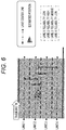
- FIG. 6 is a view for explaining the reliability of an estimation result by the third detector 1133.
- the third detector 1133 estimates the road on which the vehicle is traveling by the collation of the high-precision map 140 according to the vehicle position estimated by the position estimation unit 111.
- the third detector 1133 further acquires the coordinates of the center lines of all the lanes of the road by the collation of the high-precision map 140.
- the reliability calculation unit 1136 calculates the distance (perpendicular distance) between the estimated vehicle position and the center line of each lane. For a lane where the distance between the vehicle position and the center line is smaller, the reliability calculation unit 1136 sets the reliability to be higher. For example, the examples as described below can be considered.
- the reliability for the lane with the smallest distance to the center line is set to be the highest, and the reliabilities for the other lanes are set to a uniform value lower than the reliability for the above lane.
- a reliability is set to be inversely proportional to the distance to the center line.
- the reliabilities for lanes other than the lane with the smallest distance to the center line are set to 0.
- the fourth detector 1134 periodically acquires a measured distance from the vehicle to the lane marking that is obtained from the image of the surroundings of the vehicle, and based on the measured distance, the detector determines, for each period, whether or not the vehicle has moved between the lanes by crossing the lane marking.
- the fourth detector 1134 assumes that the traveling lane is not changed until determining that the vehicle has moved between the lanes by crossing the lane marking.
- the estimation result by the traveling lane determination unit 1138 can be used. Alternatively, an estimation result by another determination unit may be used.
- the vehicle control device 100 calculates the integrated reliability by integrating, for each lane, the reliabilities of the estimation results by the respective detectors, and finally estimates the traveling lane by comparing the integrated reliabilities with each other.
- the detection methods that the respective detectors use when estimating a traveling lane are different from each other for each detector, the detection methods including those to be used in: estimating a traveling lane using a position estimation result (the first detector 1131 to the third detector 1133); estimating a traveling lane using an image of the surroundings of the vehicle (the fourth detector 1134); estimating a traveling lane using a combination thereof (the second detector 1132); and the like. Therefore, the integrated reliability is calculated by integrating the results of estimating a traveling lane from a plurality of viewpoints. Thereby, the reliability of the final estimation result can be enhanced.
- the estimation result is prioritized over other detectors. This makes it possible to simplify the estimation processing, which is advantageous from the viewpoints of calculation load, processing time, and the like. Further, the accuracy of the vehicle position is considered to be relatively high when the vehicle is traveling on a one-lane road, so that it is also advantageous from the viewpoint of reliability.
- the fourth detector 1134 determines the traveling lane based on whether or not the vehicle has moved by crossing a lane marking. Thereby, the previous estimation result can be used until the vehicle moves by crossing a lane marking, which is advantageous from the viewpoints of calculation load, processing time, and the like.
- the reliability calculation unit 1136 sets the reliability according to the characteristics of the estimation method by each detector.
- the reliability of an estimated vehicle position itself or of an image of the surroundings itself can be obtained, the reliability of the estimation result can be set by adding its reliability. Therefore, in a second embodiment of the present invention, an example will be described in which the reliability of an estimated vehicle position itself or of an image of the surroundings itself is added as the reliability of the estimation result.
- the configuration of a vehicle control device 100 is the same as that in the first embodiment.
- a second detector 1132 estimates a traveling lane by identifying a lane marking type included in an image of the surroundings of the vehicle. Therefore, the estimation result depends on the accuracy of the image of the surroundings.
- a reliability calculation unit 1136 may set the reliability of the estimation result by the second detector 1132 to be lower than those in other cases.
- the accuracy of an image of the surroundings can be acquired from, for example, a control device that provides images of the surroundings. Alternatively, it is assumed that the accuracy of an image of the surroundings is low at night, so that the reliability may be set to be lower in the nighttime than in other time zones.
- the time may be held inside the vehicle control device 100, or when the time information obtained from a GNSS is included in, for example, the information on estimated vehicle position, the time information may be used.
- a third detector 1133 acquires the distance between the lane center line and the vehicle using the vehicle position estimated by a position estimation unit 111. Therefore, the estimation result depends on the accuracy of the estimation of the vehicle position.
- the accuracy of the estimation of the vehicle position can be calculated based on, for example, the information on positioning error obtained from a GNSS tuner 120.
- the reliability calculation unit 1136 may set the reliability of the estimation result by the third detector 1133 to be lower than those in other cases.
- the reliability may be set to emphasize the estimation result by the third detector 1133.
- a fourth detector 1134 calculates the distance between the vehicle and the lane marking. Therefore, the determination result depends on the accuracy of the image of the surroundings.
- the reliability calculation unit 1136 may set the reliability of the estimation result by the fourth detector 1134 to be lower than those in other cases. Similarly, the reliability may be set to be lower in the nighttime than in other time zones.
- the reliability calculation unit 1136 calculates the reliabilities of the estimation results by the respective detectors (1131 to 1134), and the integrated reliability calculation unit 1137 and the traveling lane determination unit 1138 determine a traveling lane using the reliabilities. Therefore, as long as the reliabilities of the estimation results can be acquired, the integrated reliability calculation unit 1137 and the traveling lane determination unit 1138 can determine the integrated reliability and the traveling lane, respectively, regardless of what procedures the respective detectors (1131 to 1134) use for estimation. By using this, the respective detectors (1131 to 1134) can be freely replaced.
- the reliability calculation unit 1136 calculates the estimation result by the first detector 1131 and delivers it to the integrated reliability calculation unit 1137.
- the reliability calculation unit 1136 handles the reliability of the estimation result by the modified first detector 1131 as the reliability of the estimation result by the first detector 1131 before modified.
- the integrated reliability calculation unit 1137 and the traveling lane determination unit 1138 can perform the same processing whether the processing is performed before or after the modification of the first detector 1131.
- the respective detectors can be freely replaced, so that the traveling lane estimation unit 113 can be flexibly reconfigured according to, for example, the type or specification of the vehicle.
- the interface between each detector and the reliability calculation unit 1136 may be set to be the same, irrespective of a case before or after the replacement.
- a common application programming interface API
- the interface such as a signal line may be set to be the same, irrespective of a case before or after the replacement.
- the present invention is not limited to the above embodiments, and includes various modifications.
- the above embodiments have been described in detail for easy understanding of the present invention, and the present invention is not necessarily limited to embodiments including all the configurations described above.
- part of the configuration of an embodiment can be replaced with the configuration of another embodiment, or the configuration of an embodiment can be added with the configuration of another embodiment.
- part of the configuration of each embodiment can be added with another configuration, or deleted or replaced.
- Some or all of the above configurations, functions, processing units, processing means, and the like may be realized by hardware in which they are designed with, for example, integrated circuits.
- the above configurations, functions, and the like may be realized by software in which a processor interprets and executes a program that realizes each function.
- Information on a program, a table, a file, etc., for realizing each function can be stored in a recording device such as a memory, a hard disk, or a solid state drive (SSD), or a recording medium such as an IC card or an SD card.
- SSD solid state drive
- the control lines and the information lines that are considered to be necessary for explanation are described, but all of the control lines and the information lines that are necessary for a product are not necessarily described. In fact, it may be considered that almost all the configurations are connected to each other.
- the traveling lane determination unit 1138 estimates the lane with the highest integrated reliability as a traveling lane.
- the traveling lane determination unit 1138 may use other methods as long as it can estimate a traveling lane by comparing the integrated reliabilities with each other. For example, it is considered to estimate the traveling lane with the maximum likelihood by comparing the time-series changes in the integrated reliabilities for the respective lanes with each other.
- a traveling lane is estimated by using a position estimation result by a GNSS tuner or a gyro sensor and an image of the surroundings.
- other sensors are used instead of or in combination with them.
- a surrounding structure of the vehicle is identified by a laser ranging sensor or a radar, and based on this, a traveling lane is estimated.
- the method of the present invention in which reliabilities are integrated for each lane by including reliability in the estimation result by each detector, can be used.
Landscapes
- Engineering & Computer Science (AREA)
- Radar, Positioning & Navigation (AREA)
- Remote Sensing (AREA)
- Physics & Mathematics (AREA)
- Automation & Control Theory (AREA)
- General Physics & Mathematics (AREA)
- Mechanical Engineering (AREA)
- Transportation (AREA)
- Computer Networks & Wireless Communication (AREA)
- Mathematical Physics (AREA)
- Theoretical Computer Science (AREA)
- Multimedia (AREA)
- Computer Vision & Pattern Recognition (AREA)
- Traffic Control Systems (AREA)
- Navigation (AREA)
- Control Of Driving Devices And Active Controlling Of Vehicle (AREA)
Abstract
Description
- The present invention relates to a vehicle control device that controls operations of a vehicle.
- Techniques for automatically driving a vehicle are currently under active development. In the automatic driving, it is important to estimate the position of a vehicle with high accuracy. In general, the position of a vehicle can be estimated with high accuracy by combining the absolute position, orientation, and vehicle speed of a vehicle that are estimated by, for example, a global navigation satellite system (GNSS) with the relative amount of movement of the vehicle that is estimated by a vehicle speed sensor or a gyro sensor.
- When a vehicle control device supports vehicle driving by a driver, it may be useful to estimate which lane of a road a vehicle is traveling in, in addition to the position of the vehicle. For example, in a situation where a vehicle is traveling on an expressway, it can be thought that by estimating a lane (traveling lane) in which the vehicle is traveling, it is determined which of the main line of the expressway or a branch road the vehicle is traveling on, so that driving support suitable for a road type is provided.
- The following
PTL 1 discloses a technique for estimating a traveling lane. The purpose of thePTL 1 is to "accurately estimate whether or not one's own vehicle has entered a branch road that branches off from the main line of a traveling road." ThePTL 1 discloses a technique in which "the number of lanes of the road on which the one's own vehicle is traveling is detected (S110), the number of the lanes and the traveling lane for the one's own vehicle are estimated from a detection result by a delineator (S120), and the number of the lanes and the traveling lane for the one's own vehicle are estimated from a detection result of the preceding vehicle (S130). Then, based on "the number of lanes of the road on which the one's own vehicle is traveling" detected in S110, "the estimation result of the traveling lane based on the delineator", and "the estimation result of the traveling lane based on the preceding vehicle," the traveling lane for the one's own vehicle is estimated (S140). Therefore, the reliability of the estimation result of the traveling lane can be enhanced, and it can be accurately estimated based on the estimation result whether or not the one's own vehicle has entered a branch road that branches off from the main line of the traveling road." (see ABSTRACT). - PTL 1:
JP 2004-341941 A - In the conventional traveling lane estimation, it is common to estimate a traveling lane using a single detection method. In such a method, the reliability of the estimation result itself decreases in an environment where, for example, the accuracy of a sensor used in the detection method decreases.
- When a plurality of detection methods are used as in the
above PTL 1, and if any of the detection methods is low in accuracy, the low-accurate detection method may adversely affect the final estimation result. If detection methods each assumed to have a sufficiently high accuracy are only adopted, it is difficult to sufficiently exhibit the effect of using a plurality of detection methods. - The present invention has been made in view of the above problems, and an object of the present invention is to provide a technique that when a traveling lane is determined by using a plurality of detection methods, can accurately estimate the traveling lane even if any of the detection methods is not sufficient in accuracy.
- A vehicle control device according to the present invention calculates integrated reliabilities by integrating reliabilities of traveling lane estimation results by a first detector and the reliabilities of traveling lane estimation results by a second detector, and estimates a traveling lane by comparing the integrated reliabilities with each other.
- According to the vehicle control device of the present invention, the reliabilities of the respective estimation results by the respective detectors are integrated and compared with each other, so that a traveling lane can be accurately estimated even if the accuracy of the estimation result by any of the detectors is not sufficient.
- Further, according to the vehicle control device of the present invention, the estimation results by the respective detectors are compared with each other by a unified measure of reliability, so that a detector can be easily added or deleted.
-
- [
FIG. 1] FIG. 1 is a configuration view of avehicle control device 100 according to a first embodiment. - [
FIG. 2] FIG. 2 is a detailed configuration view of a travelinglane estimation unit 113. - [
FIG. 3] FIG. 3 is a view for explaining a procedure for calculating integrated reliability by an integratedreliability calculation unit 1137. - [
FIG. 4] FIG. 4 is a view for explaining the reliability of an estimation result by afirst detector 1131. - [
FIG. 5] FIG. 5 is a view for explaining the reliability of an estimation result by asecond detector 1132. - [
FIG. 6] FIG. 6 is a view for explaining the reliability of an estimation result by athird detector 1133. -
FIG. 1 is a configuration view of avehicle control device 100 according to a first embodiment of the present invention. Thevehicle control device 100 is a device that controls operations of a vehicle, and is mounted in the vehicle. Thevehicle control device 100 includes acalculation unit 110, aGNSS tuner 120, agyro sensor 130, and a high-precision map 140. Thecalculation unit 110 has aposition estimation unit 111, a travelinglane estimation unit 113, and aposition correction unit 114. - The GNSS
tuner 120 acquires the absolute position, orientation, and moving speed of the vehicle from a GNSS. Thegyro sensor 130 measures an angular velocity for each rotation axis of the vehicle and estimates the attitude of the vehicle. - As the rotation axis, only a yaw axis or three axes including also a pitch axis and a roll is/are generally measured. The high-
precision map 140 is stored in advance in a storage device included in thevehicle control device 100. For example, coordinates of road center lines and lane markings constituting traveling lanes can be stored as the high-precision map 140. - The
position estimation unit 111 estimates the position of the vehicle by using information such as the absolute position, orientation, and moving speed acquired by theGNSS tuner 120, and the angular velocity and vehicle speed of the vehicle acquired by thegyro sensor 130. The travelinglane estimation unit 113 estimates the road on and the traveling lane in which the vehicle is traveling by comparing the position of the vehicle with the high-precision map 140. Details will be described later. Theposition correction unit 114 acquires an image of the surroundings of the vehicle from an imaging device such as a camera in order to correct the position of the vehicle based on the image of the surroundings. -
FIG. 2 is a detailed configuration view of the travelinglane estimation unit 113. The travelinglane estimation unit 113 includes a plurality of detectors that estimate a traveling lane. In the first embodiment, an example in which afirst detector 1131 to afourth detector 1134 are provided has been described. Each detector estimates a traveling lane by detection means and an estimation method that are different from those of the other detectors. A specific estimation method by each detector will be described later. - The traveling
lane estimation unit 113 further includes areliability calculation unit 1136, an integratedreliability calculation unit 1137, and a travelinglane determination unit 1138. Thereliability calculation unit 1136 calculates the reliability of an estimation result by each detector. Alternatively, each detector may calculate the reliability by itself. Hereinafter, it is assumed, for convenience of description, that thereliability calculation unit 1136 calculates the reliability. The integratedreliability calculation unit 1137 calculates integrated reliability by integrating the reliabilities for each lane. A specific example of calculating the integrated reliability will be described later. The travelinglane determination unit 1138 finally estimates a traveling lane by comparing the integrated reliabilities with each other. The estimation result is output as, for example, a lane number and its reliability. -
FIG. 3 is a view for explaining a procedure for calculating the integrated reliability by the integratedreliability calculation unit 1137. - Here, a scene is assumed, in which the vehicle is traveling on a road with four lanes. The number of estimation results of a traveling lane output by each detector is not necessarily one, and a plurality of candidates for a traveling lane may be output as the estimation result. The
reliability calculation unit 1136 calculates reliability for each candidate. In the example shown inFIG. 3 , it is assumed that the reliabilities as shown in the table inFIG. 3 are obtained for the estimation result of each detector. - The integrated
reliability calculation unit 1137 integrates, for each lane, the reliabilities of the estimation results by the respective detectors. For example, thesecond detector 1132 and thethird detector 1133 each output thelane number 3 as a candidate for the traveling lane, the reliabilities of which are 80 and 40, respectively. The other detectors do not recognize thelane number 3 as a candidate for the traveling lane. Therefore, the total of the reliabilities for thelane number 3 is 120. Also, for the other lane numbers, reliabilities are similarly integrated for each lane. Here, the reliabilities are integrated by simply adding together, but, for example, weighting can also be applied to each detector. For example, when the estimation result by thefirst detector 1131 is emphasized, the weight related to thefirst detector 1131 may be made greater than the weights related to the other detectors. - The integrated
reliability calculation unit 1137 further calculates the integrated reliability for each lane by determining a relative ratio of the reliability integrated for each lane. In the example shown inFIG. 3 , the grand total of the reliabilities of the estimation results by the respective detectors is 375 and the total of the reliabilities for thelane number 3 is 120. Therefore, the integrated reliability for thelane number 3 is 120/375 × 100 = 32. Also, for the other lane numbers, the integrated reliabilities are similarly calculated. - The integrated reliability is obtained by integrating the estimation results by the respective detectors across lanes. Therefore, even if the reliability of the estimation result by any of the detectors is low, the accuracy of the integrated reliability is considered to be sufficiently high if the reliabilities of the estimation results by the other detectors are high. In the first embodiment, a traveling lane is estimated by comparing the integrated reliabilities with each other based on such an idea. Therefore, the traveling
lane determination unit 1138 outputs the lane number having the highest integrated reliability and the integrated reliability thereof as the estimation result. -
FIG. 4 is a view for explaining the reliability of the estimation result by thefirst detector 1131. Thefirst detector 1131 determines whether or not the vehicle is traveling on a road with only one lane (one-lane road) by the collation of the high-precision map 140 according to the vehicle position estimated by theposition estimation unit 111. Whether or not the vehicle is traveling on a one-lane road can be determined by, for example, acquiring the number of lanes of the road and according to whether or not the number of the lanes is one. Thereliability calculation unit 1136 sets the reliability in a section, where thefirst detector 1131 determines that the vehicle is traveling on a one-lane road, to be higher than those in other sections. For example, the examples as described below can be considered. - When compared in a section where the
first detector 1131 determines that the vehicle is traveling on a one-lane road and in other sections, the reliability of the estimation result by thefirst detector 1131 is set to be higher in the former section. For example, the reliability for thefirst detector 1131 in a section where the vehicle is traveling on a one-lane road is 100, and the reliability for thefirst detector 1131 in other sections is 0, as shown inFIG. 4 . - In a section where the
first detector 1131 determines that the vehicle is traveling on a one-lane road, the reliability of the estimation result by thefirst detector 1131 is set to be higher than the reliabilities of the determination results by the other detectors. For example, the reliability for thefirst detector 1131 in a section where the vehicle is traveling on a one-lane road is 100, and the reliabilities for the other detectors are set to be less than 100 even if those detectors are sufficiently reliable. In other sections, the reliabilities for the respective detectors are treated equally. - In a section where the
first detector 1131 estimates that the vehicle is traveling on a one-lane road, the travelinglane determination unit 1138 assumes that the vehicle is traveling on the one-lane road regardless of the estimation results by the other detectors. This is because when the accuracy of the vehicle position is sufficiently high, there is little significance in estimating a traveling lane on a road with only one lane. Specifically, the estimation result by thefirst detector 1131 may be adopted by setting the reliability for thefirst detector 1131 to be extremely high, or the travelinglane determination unit 1138 may finally determine the traveling lane by skipping the integratedreliability calculation unit 1137. -
FIG. 5 is a view for explaining the reliability of the estimation result by thesecond detector 1132. Thesecond detector 1132 acquires the number of lanes and information on the lane marking type of the road on which the vehicle is currently traveling, by the collation of the high-precision map 140 according to the vehicle position estimated by theposition estimation unit 111. Thesecond detector 1132 further estimates the lane in which the vehicle is traveling by identifying the lane marking type of the road included in the image of the surroundings of the vehicle. - In the example shown in
FIG. 5 , the lane marking on the left side of the vehicle is a solid line and the lane marking on the right side of the vehicle is a dotted line, as a result of identifying the lane marking type based on the image of the surroundings. Thesecond detector 1132 can further determine that based on a result of the collation of the high-precision map 140, the lane of the road on which the vehicle is traveling, in which the left lane marking is a solid line and the right lane marking is a dotted line, is only alane 1. Therefore, thesecond detector 1132 estimates that the vehicle is traveling in thelane 1. - The
reliability calculation unit 1136 sets the reliability for the traveling lane, which thesecond detector 1132 has estimated based on the lane marking type, to be higher than those for the other lanes. In the example shown inFIG. 5 , thesecond detector 1132 has determined that the vehicle is traveling in thelane 1 based on a section line type. Therefore, the reliability for thelane 1 is set to be higher than the reliabilities for the other lanes. - In another example shown in
FIG. 5 , when the lane markings on both sides of the vehicle are dotted lines, thesecond detector 1132 estimates that the vehicle is traveling in alane 2 or alane 3. In this case, one traveling lane cannot be determined in the estimation, so that the reliability may be set to be lower than that when thelane 1 or alane 4 is estimated as the traveling lane. -
FIG. 6 is a view for explaining the reliability of an estimation result by thethird detector 1133. Thethird detector 1133 estimates the road on which the vehicle is traveling by the collation of the high-precision map 140 according to the vehicle position estimated by theposition estimation unit 111. Thethird detector 1133 further acquires the coordinates of the center lines of all the lanes of the road by the collation of the high-precision map 140. - The
reliability calculation unit 1136 calculates the distance (perpendicular distance) between the estimated vehicle position and the center line of each lane. For a lane where the distance between the vehicle position and the center line is smaller, thereliability calculation unit 1136 sets the reliability to be higher. For example, the examples as described below can be considered. (a) The reliability for the lane with the smallest distance to the center line is set to be the highest, and the reliabilities for the other lanes are set to a uniform value lower than the reliability for the above lane. (b) A reliability is set to be inversely proportional to the distance to the center line. (c) The reliabilities for lanes other than the lane with the smallest distance to the center line are set to 0. - The
fourth detector 1134 periodically acquires a measured distance from the vehicle to the lane marking that is obtained from the image of the surroundings of the vehicle, and based on the measured distance, the detector determines, for each period, whether or not the vehicle has moved between the lanes by crossing the lane marking. Thefourth detector 1134 assumes that the traveling lane is not changed until determining that the vehicle has moved between the lanes by crossing the lane marking. For each of the traveling lanes before and after the change, the estimation result by the travelinglane determination unit 1138 can be used. Alternatively, an estimation result by another determination unit may be used. - The
vehicle control device 100 according to the first embodiment calculates the integrated reliability by integrating, for each lane, the reliabilities of the estimation results by the respective detectors, and finally estimates the traveling lane by comparing the integrated reliabilities with each other. Thereby, even if the reliability of a detection method (a detector such as a camera or a GNSS tuner, or an estimation method) used by any of the detectors is low, an accurate estimation result can be obtained with the low reliability compensated for, by integrating the reliabilities of the detection methods used by the other detectors. - In the
vehicle control device 100 according to the first embodiment, the detection methods that the respective detectors use when estimating a traveling lane are different from each other for each detector, the detection methods including those to be used in: estimating a traveling lane using a position estimation result (thefirst detector 1131 to the third detector 1133); estimating a traveling lane using an image of the surroundings of the vehicle (the fourth detector 1134); estimating a traveling lane using a combination thereof (the second detector 1132); and the like. Therefore, the integrated reliability is calculated by integrating the results of estimating a traveling lane from a plurality of viewpoints. Thereby, the reliability of the final estimation result can be enhanced. - In the
vehicle control device 100 according to the first embodiment, when thefirst detector 1131 determines that the vehicle is traveling on a one-lane road, the estimation result is prioritized over other detectors. This makes it possible to simplify the estimation processing, which is advantageous from the viewpoints of calculation load, processing time, and the like. Further, the accuracy of the vehicle position is considered to be relatively high when the vehicle is traveling on a one-lane road, so that it is also advantageous from the viewpoint of reliability. - In the
vehicle control device 100 according to the first embodiment, thefourth detector 1134 determines the traveling lane based on whether or not the vehicle has moved by crossing a lane marking. Thereby, the previous estimation result can be used until the vehicle moves by crossing a lane marking, which is advantageous from the viewpoints of calculation load, processing time, and the like. - In the first embodiment, it has been described that the
reliability calculation unit 1136 sets the reliability according to the characteristics of the estimation method by each detector. When in addition to this, the reliability of an estimated vehicle position itself or of an image of the surroundings itself can be obtained, the reliability of the estimation result can be set by adding its reliability. Therefore, in a second embodiment of the present invention, an example will be described in which the reliability of an estimated vehicle position itself or of an image of the surroundings itself is added as the reliability of the estimation result. The configuration of avehicle control device 100 is the same as that in the first embodiment. - A
second detector 1132 estimates a traveling lane by identifying a lane marking type included in an image of the surroundings of the vehicle. Therefore, the estimation result depends on the accuracy of the image of the surroundings. When the accuracy of the image of the surroundings is low, areliability calculation unit 1136 may set the reliability of the estimation result by thesecond detector 1132 to be lower than those in other cases. The accuracy of an image of the surroundings can be acquired from, for example, a control device that provides images of the surroundings. Alternatively, it is assumed that the accuracy of an image of the surroundings is low at night, so that the reliability may be set to be lower in the nighttime than in other time zones. The time may be held inside thevehicle control device 100, or when the time information obtained from a GNSS is included in, for example, the information on estimated vehicle position, the time information may be used. - A
third detector 1133 acquires the distance between the lane center line and the vehicle using the vehicle position estimated by aposition estimation unit 111. Therefore, the estimation result depends on the accuracy of the estimation of the vehicle position. The accuracy of the estimation of the vehicle position can be calculated based on, for example, the information on positioning error obtained from aGNSS tuner 120. When the accuracy of the estimation of the vehicle position is low, thereliability calculation unit 1136 may set the reliability of the estimation result by thethird detector 1133 to be lower than those in other cases. When the accuracy of the estimation of the vehicle position is high, the reliability may be set to emphasize the estimation result by thethird detector 1133. - After identifying the lane marking type included in an image of the surroundings of the vehicle, a
fourth detector 1134 calculates the distance between the vehicle and the lane marking. Therefore, the determination result depends on the accuracy of the image of the surroundings. - When the accuracy of the image of the surroundings is low, the
reliability calculation unit 1136 may set the reliability of the estimation result by thefourth detector 1134 to be lower than those in other cases. Similarly, the reliability may be set to be lower in the nighttime than in other time zones. - In the first and second embodiments, the
reliability calculation unit 1136 calculates the reliabilities of the estimation results by the respective detectors (1131 to 1134), and the integratedreliability calculation unit 1137 and the travelinglane determination unit 1138 determine a traveling lane using the reliabilities. Therefore, as long as the reliabilities of the estimation results can be acquired, the integratedreliability calculation unit 1137 and the travelinglane determination unit 1138 can determine the integrated reliability and the traveling lane, respectively, regardless of what procedures the respective detectors (1131 to 1134) use for estimation. By using this, the respective detectors (1131 to 1134) can be freely replaced. - For example, it is assumed that the detection procedure to be performed by the
first detector 1131 is updated and thefirst detector 1131 is replaced with a modifiedfirst detector 1131. Irrespective of a case before or after thefirst detector 1131 is replaced with the modified one, thereliability calculation unit 1136 calculates the estimation result by thefirst detector 1131 and delivers it to the integratedreliability calculation unit 1137. In other words, thereliability calculation unit 1136 handles the reliability of the estimation result by the modifiedfirst detector 1131 as the reliability of the estimation result by thefirst detector 1131 before modified. Thereby, the integratedreliability calculation unit 1137 and the travelinglane determination unit 1138 can perform the same processing whether the processing is performed before or after the modification of thefirst detector 1131. The same applies to the other detectors. Thereby, the respective detectors can be freely replaced, so that the travelinglane estimation unit 113 can be flexibly reconfigured according to, for example, the type or specification of the vehicle. - In order to enable the respective detectors to be freely replaced, the interface between each detector and the
reliability calculation unit 1136 may be set to be the same, irrespective of a case before or after the replacement. For example, when each detector is configured as a software module, a common application programming interface (API) for transmitting and receiving estimation results between each module and thereliability calculation unit 1136 may be provided in advance in order that any module, before and after the replacement, transmits and receives estimation results via the API. Also, when each detector is configured by hardware, the interface such as a signal line may be set to be the same, irrespective of a case before or after the replacement. - The present invention is not limited to the above embodiments, and includes various modifications. For example, the above embodiments have been described in detail for easy understanding of the present invention, and the present invention is not necessarily limited to embodiments including all the configurations described above. Additionally, part of the configuration of an embodiment can be replaced with the configuration of another embodiment, or the configuration of an embodiment can be added with the configuration of another embodiment. Additionally, part of the configuration of each embodiment can be added with another configuration, or deleted or replaced.
- Some or all of the above configurations, functions, processing units, processing means, and the like may be realized by hardware in which they are designed with, for example, integrated circuits. Alternatively, the above configurations, functions, and the like may be realized by software in which a processor interprets and executes a program that realizes each function. Information on a program, a table, a file, etc., for realizing each function can be stored in a recording device such as a memory, a hard disk, or a solid state drive (SSD), or a recording medium such as an IC card or an SD card. Additionally, the control lines and the information lines that are considered to be necessary for explanation are described, but all of the control lines and the information lines that are necessary for a product are not necessarily described. In fact, it may be considered that almost all the configurations are connected to each other.
- In the above embodiments, it has been described that the traveling
lane determination unit 1138 estimates the lane with the highest integrated reliability as a traveling lane. The travelinglane determination unit 1138 may use other methods as long as it can estimate a traveling lane by comparing the integrated reliabilities with each other. For example, it is considered to estimate the traveling lane with the maximum likelihood by comparing the time-series changes in the integrated reliabilities for the respective lanes with each other. - In the above embodiments, it has been described that a traveling lane is estimated by using a position estimation result by a GNSS tuner or a gyro sensor and an image of the surroundings. But, it can also be considered that instead of or in combination with them, other sensors are used. For example, it can be considered that a surrounding structure of the vehicle is identified by a laser ranging sensor or a radar, and based on this, a traveling lane is estimated. Even in that case, the method of the present invention, in which reliabilities are integrated for each lane by including reliability in the estimation result by each detector, can be used.
-
- 100
- vehicle control device
- 110
- calculation unit
- 111
- position estimation unit
- 113
- traveling lane estimation unit
- 1131
- first detector
- 1132
- second detector
- 1133
- third detector
- 1134
- fourth detector
- 1136
- reliability calculation unit
- 1137
- integrated reliability calculation unit
- 1138
- traveling lane determination unit
- 114
- position correction unit
- 120
- GNSS tuner
- 130
- gyro sensor
- 140
- high-precision map
Claims (11)
- A vehicle control device that controls operations of a vehicle, the vehicle control device comprising:first and second detectors that estimate a lane in which the vehicle is traveling;a reliability calculation unit that calculates reliabilities of estimation results by the respective first and second detectors;an integrated reliability calculation unit that calculates integrated reliability in which the reliabilities are integrated for each lane; anda traveling lane determination unit that estimates a lane in which the vehicle is traveling by using the integrated reliability,wherein:the first detector estimates the lane using a first detection procedure, and the second detector estimates the lane using a second detection procedure different from the first detection procedure;the integrated reliability calculation unit calculates a first integrated reliability, representing a probability that the vehicle is traveling in a first lane, by using the reliability of a result of the first detector estimating that the vehicle is traveling in the first lane, and the reliability of a result of the second detector estimating that the vehicle is traveling in the first lane;the integrated reliability calculation unit calculates a second integrated reliability, representing a probability that the vehicle is traveling in a second lane, by using the reliability of a result of the first detector estimating that the vehicle is traveling in the second lane, and the reliability of a result of the second detector estimating that the vehicle is traveling in the second lane; andthe traveling lane determination unit estimates a lane in which the vehicle is traveling by comparing the first integrated reliability and the second integrated reliability.
- The vehicle control device according to claim 1, further comprising: a position estimation unit that estimates a position of a vehicle; and map data stored in a storage device, wherein: the first detector acquires a position of the vehicle via the position estimation unit and acquires the number of lanes of a road on which the vehicle is traveling using the map data; and
when the first detector estimates that the number of lanes of the road on which the vehicle is traveling is one, the traveling lane determination unit assumes that the vehicle is traveling in the lane. - The vehicle control device according to claim 1, further comprising: a position estimation unit that estimates a position of a vehicle; and map data stored in a storage device, wherein: the first detector acquires a position of the vehicle via the position estimation unit and acquires the number of lanes of a road on which the vehicle is traveling using the map data; and
in a road section in which the first detector estimates that the number of lanes of the road on which the vehicle is traveling is one, the reliability calculation unit sets the reliability of the estimation result by the first detector to be higher than in other road sections. - The vehicle control device according to claim 1, further comprising: a position estimation unit that estimates a position of a vehicle; and map data stored in a storage device, wherein: the first detector acquires a position of the vehicle via the position estimation unit and acquires the number of lanes of a road on which the vehicle is traveling using the map data; and
when the first detector estimates that the number of lanes of the road on which the vehicle is traveling is one, the reliability calculation unit sets the reliability of the estimation result by the first detector to be higher than the reliability of the estimation result by the second detector. - The vehicle control device according to claim 1, further comprising: a position estimation unit that estimates a position of a vehicle; map data stored in a storage device; and an image acquisition device that acquires an image of surroundings of a vehicle, wherein: the first detector acquires the image of the surroundings of the vehicle and specifies a lane marking type of a road included in the image of the surroundings to estimate the lane, and the first detector further acquires a position of the vehicle via the position estimation unit and determines the lane using the map data; and
for a lane where the estimation result by the first detector generated when the image of the surroundings is used matches the estimation result by the first detector generated when the position of the vehicle and the map data are used, the reliability calculation unit sets the reliability to be higher than those of the other lanes. - The vehicle control device according to claim 1, further comprising: a position estimation unit that estimates a position of a vehicle; and map data stored in a storage device, wherein: the first detector acquires a position of the vehicle via the position estimation unit and acquires coordinates of a center line of a lane using the map data;the reliability calculation unit calculates a first distance between the position of the vehicle and the center line of each lane that are acquired by the first detector; andfor a lane where the first distance is smaller, the reliability calculation unit sets the reliability to be higher.
- The vehicle control device according to claim 1, further comprising an image acquisition device that acquires an image of surroundings of a vehicle, wherein: the first detector acquires the image of the surroundings of the vehicle and determines whether or not the vehicle has crossed a section line of a road using the image of the surroundings; and
the first detector assumes that the vehicle continues traveling without changing a lane while the vehicle has not crossed the section line of the road. - The vehicle control device according to claim 1, wherein the integrated reliability calculation unit calculates the first or second integrated reliability by multiplying the estimation result by the first detector by a first weight and multiplying the estimation result by the second detector by a second weight.
- The vehicle control device according to claim 1, further comprising an image acquisition device that acquires an image of surroundings of a vehicle, wherein: the reliability calculation unit acquires information indicating accuracy of the image of the surroundings of the vehicle; and
the reliability calculation unit adjusts the reliability of one of the estimation result by the first detector and the estimation result by the second detector according to the accuracy, the one obtained by using the image of the surroundings. - The vehicle control device according to claim 1, wherein: the reliability calculation unit acquires information indicating accuracy of estimation by a position estimation unit; and
the reliability calculation unit adjusts the reliability of one of the estimation result by the first detector and the estimation result by the second detector according to the accuracy of the estimation, the one obtained by using the position estimation unit. - The vehicle control device according to claim 1, wherein:the first detector is configured to be replaceable with a modified first detector that estimates the lane using a procedure different from the first detection procedure; andthe reliability calculation unit calculates the reliability of an estimation result by the modified first detector as the reliability of the estimation result by the first detector, so that the integrated reliability calculation unit and the traveling lane determination unit can perform the same processing whether the processing is performed before or after replacement of the first detector with the modified first detector.
Applications Claiming Priority (2)
| Application Number | Priority Date | Filing Date | Title |
|---|---|---|---|
| JP2019044343 | 2019-03-12 | ||
| PCT/JP2020/004723 WO2020184013A1 (en) | 2019-03-12 | 2020-02-07 | Vehicle control device |
Publications (3)
| Publication Number | Publication Date |
|---|---|
| EP3882885A1 true EP3882885A1 (en) | 2021-09-22 |
| EP3882885A4 EP3882885A4 (en) | 2022-11-23 |
| EP3882885B1 EP3882885B1 (en) | 2026-04-15 |
Family
ID=72427271
Family Applications (1)
| Application Number | Title | Priority Date | Filing Date |
|---|---|---|---|
| EP20770704.3A Active EP3882885B1 (en) | 2019-03-12 | 2020-02-07 | Vehicle control device |
Country Status (5)
| Country | Link |
|---|---|
| US (1) | US11796324B2 (en) |
| EP (1) | EP3882885B1 (en) |
| JP (1) | JP7113134B2 (en) |
| CN (1) | CN113544758B (en) |
| WO (1) | WO2020184013A1 (en) |
Cited By (1)
| Publication number | Priority date | Publication date | Assignee | Title |
|---|---|---|---|---|
| US11920936B2 (en) | 2021-03-29 | 2024-03-05 | Toyota Jidosha Kabushiki Kaisha | Vehicle controller, and method and computer program for controlling vehicle |
Families Citing this family (6)
| Publication number | Priority date | Publication date | Assignee | Title |
|---|---|---|---|---|
| JP7150900B2 (en) * | 2021-01-12 | 2022-10-11 | 本田技研工業株式会社 | Vehicle system for determining recommended lanes |
| KR20220114750A (en) * | 2021-02-09 | 2022-08-17 | 현대모비스 주식회사 | System for recognizing lange and control method for the same |
| JP7196220B2 (en) * | 2021-03-30 | 2022-12-26 | 本田技研工業株式会社 | VEHICLE CONTROL DEVICE, VEHICLE CONTROL METHOD, AND PROGRAM |
| DE102021109425B3 (en) * | 2021-04-15 | 2022-07-21 | Bayerische Motoren Werke Aktiengesellschaft | Method for controlling a vehicle and control device for a vehicle |
| EP4134623A1 (en) * | 2021-08-11 | 2023-02-15 | Hitachi Astemo, Ltd. | Drive device, vehicle, and method for automated driving and/or assisted driving |
| JP7694297B2 (en) * | 2021-09-22 | 2025-06-18 | 株式会社Soken | Vehicle position estimation device |
Family Cites Families (16)
| Publication number | Priority date | Publication date | Assignee | Title |
|---|---|---|---|---|
| JP2004085337A (en) * | 2002-08-27 | 2004-03-18 | Fujitsu Ltd | Vehicle detection method and vehicle detection device |
| JP4055650B2 (en) | 2003-05-16 | 2008-03-05 | 株式会社デンソー | Branch approach estimation device, vehicle speed control device, and program |
| JP4544987B2 (en) * | 2004-09-06 | 2010-09-15 | ダイハツ工業株式会社 | Collision prediction method and collision prediction apparatus |
| JP4517972B2 (en) * | 2005-08-02 | 2010-08-04 | 日産自動車株式会社 | Obstacle determination device and method |
| JP5136314B2 (en) * | 2008-09-16 | 2013-02-06 | トヨタ自動車株式会社 | Lane recognition device |
| JP2015001773A (en) | 2013-06-13 | 2015-01-05 | ボッシュ株式会社 | Lane estimation device |
| CN104240509A (en) * | 2014-10-10 | 2014-12-24 | 南京莱斯信息技术股份有限公司 | Comprehensive video detection system for transport vehicles |
| CN104794895A (en) * | 2015-04-09 | 2015-07-22 | 吉林大学 | A Multi-source Traffic Information Fusion Method for Freeway |
| JP6649047B2 (en) * | 2015-11-11 | 2020-02-19 | トヨタ自動車株式会社 | Vehicle travel control device |
| DE102016213782A1 (en) | 2016-07-27 | 2018-02-01 | Volkswagen Aktiengesellschaft | A method, apparatus and computer readable storage medium having instructions for determining the lateral position of a vehicle relative to the lanes of a lane |
| JP2019532292A (en) * | 2016-09-29 | 2019-11-07 | ザ・チャールズ・スターク・ドレイパー・ラボラトリー・インコーポレイテッド | Autonomous vehicle with vehicle location |
| KR101866075B1 (en) * | 2016-10-20 | 2018-06-08 | 현대자동차주식회사 | Apparatus and method for estmating lane |
| WO2018168961A1 (en) | 2017-03-16 | 2018-09-20 | 株式会社デンソー | Own-position estimating device |
| JP6693496B2 (en) * | 2017-03-16 | 2020-05-13 | 株式会社デンソー | Self-location estimation device |
| DE102017123842A1 (en) * | 2017-10-13 | 2019-04-18 | Connaught Electronics Ltd. | Lane detection method |
| WO2019152488A2 (en) * | 2018-02-01 | 2019-08-08 | ThorDrive, Inc. | Method for estimating position of ego vehicle for autonomous driving and autonomous driving apparatus |
-
2020
- 2020-02-07 JP JP2021505599A patent/JP7113134B2/en active Active
- 2020-02-07 CN CN202080011215.7A patent/CN113544758B/en active Active
- 2020-02-07 EP EP20770704.3A patent/EP3882885B1/en active Active
- 2020-02-07 WO PCT/JP2020/004723 patent/WO2020184013A1/en not_active Ceased
- 2020-02-07 US US17/436,984 patent/US11796324B2/en active Active
Cited By (1)
| Publication number | Priority date | Publication date | Assignee | Title |
|---|---|---|---|---|
| US11920936B2 (en) | 2021-03-29 | 2024-03-05 | Toyota Jidosha Kabushiki Kaisha | Vehicle controller, and method and computer program for controlling vehicle |
Also Published As
| Publication number | Publication date |
|---|---|
| JP7113134B2 (en) | 2022-08-04 |
| JPWO2020184013A1 (en) | 2021-10-28 |
| EP3882885B1 (en) | 2026-04-15 |
| WO2020184013A1 (en) | 2020-09-17 |
| CN113544758A (en) | 2021-10-22 |
| CN113544758B (en) | 2023-01-10 |
| US20220178703A1 (en) | 2022-06-09 |
| US11796324B2 (en) | 2023-10-24 |
| EP3882885A4 (en) | 2022-11-23 |
Similar Documents
| Publication | Publication Date | Title |
|---|---|---|
| US11796324B2 (en) | Vehicle control device | |
| KR102463176B1 (en) | Device and method to estimate position | |
| JP7190493B2 (en) | How to estimate a vehicle's position on a map | |
| US9921065B2 (en) | Unit and method for improving positioning accuracy | |
| CN109435955B (en) | Performance evaluation method, device and equipment for automatic driving system and storage medium | |
| KR20200044420A (en) | Method and device to estimate position | |
| KR102441073B1 (en) | Apparatus for compensating sensing value of gyroscope sensor, system having the same and method thereof | |
| EP3842735B1 (en) | Position coordinates estimation device, position coordinates estimation method, and program | |
| KR102006291B1 (en) | Method for estimating pose of moving object of electronic apparatus | |
| JP2019513996A (en) | Method of determining the attitude of at least a partially autonomous driving vehicle in the vicinity by a ground sign | |
| US11983890B2 (en) | Method and apparatus with motion information estimation | |
| WO2020189079A1 (en) | Own position estimating device, automatic driving system comprising same, and own generated map sharing device | |
| KR102209422B1 (en) | Rtk gnss based driving license test vehicle position determination device | |
| CN111026081B (en) | Error calculation method, device, equipment and storage medium | |
| CN115790613B (en) | Visual information-assisted inertial/odometer combined navigation method and device | |
| US20260063776A1 (en) | Method for calibrating offsets between doppler-based sensors on a mobile platform | |
| JP2019120629A (en) | Position calculation device, position calculation program, and coordinate marker | |
| EP2905579B1 (en) | Passive altimeter | |
| US10830906B2 (en) | Method of adaptive weighting adjustment positioning | |
| CN115777120B (en) | Map processing system and computer-readable recording medium | |
| JP2001264091A (en) | Navigation device | |
| CN117848331B (en) | Positioning method and device based on visual label map | |
| US12561922B2 (en) | Capture and display of point clouds using augmented reality device | |
| KR102739819B1 (en) | Dead Reckoning Algorithm Based on Geographic Information Systems | |
| US20260038150A1 (en) | Augmented reality device calibration using distance measurements |
Legal Events
| Date | Code | Title | Description |
|---|---|---|---|
| STAA | Information on the status of an ep patent application or granted ep patent |
Free format text: STATUS: THE INTERNATIONAL PUBLICATION HAS BEEN MADE |
|
| PUAI | Public reference made under article 153(3) epc to a published international application that has entered the european phase |
Free format text: ORIGINAL CODE: 0009012 |
|
| STAA | Information on the status of an ep patent application or granted ep patent |
Free format text: STATUS: REQUEST FOR EXAMINATION WAS MADE |
|
| 17P | Request for examination filed |
Effective date: 20210617 |
|
| AK | Designated contracting states |
Kind code of ref document: A1 Designated state(s): AL AT BE BG CH CY CZ DE DK EE ES FI FR GB GR HR HU IE IS IT LI LT LU LV MC MK MT NL NO PL PT RO RS SE SI SK SM TR |
|
| DAV | Request for validation of the european patent (deleted) | ||
| DAX | Request for extension of the european patent (deleted) | ||
| A4 | Supplementary search report drawn up and despatched |
Effective date: 20221020 |
|
| RIC1 | Information provided on ipc code assigned before grant |
Ipc: G01C 21/32 20060101ALI20221014BHEP Ipc: G01C 21/36 20060101ALI20221014BHEP Ipc: G01C 21/28 20060101ALI20221014BHEP Ipc: B60W 40/02 20060101ALI20221014BHEP Ipc: G08G 1/16 20060101AFI20221014BHEP |
|
| STAA | Information on the status of an ep patent application or granted ep patent |
Free format text: STATUS: EXAMINATION IS IN PROGRESS |
|
| 17Q | First examination report despatched |
Effective date: 20230810 |
|
| RAP3 | Party data changed (applicant data changed or rights of an application transferred) |
Owner name: ASTEMO, LTD. |
|
| GRAP | Despatch of communication of intention to grant a patent |
Free format text: ORIGINAL CODE: EPIDOSNIGR1 |
|
| STAA | Information on the status of an ep patent application or granted ep patent |
Free format text: STATUS: GRANT OF PATENT IS INTENDED |
|
| INTG | Intention to grant announced |
Effective date: 20251118 |
|
| GRAS | Grant fee paid |
Free format text: ORIGINAL CODE: EPIDOSNIGR3 |
|
| P01 | Opt-out of the competence of the unified patent court (upc) registered |
Free format text: CASE NUMBER: UPC_APP_0003326_3882885/2026 Effective date: 20260130 |
|
| GRAA | (expected) grant |
Free format text: ORIGINAL CODE: 0009210 |
|
| STAA | Information on the status of an ep patent application or granted ep patent |
Free format text: STATUS: THE PATENT HAS BEEN GRANTED |
|
| AK | Designated contracting states |
Kind code of ref document: B1 Designated state(s): AL AT BE BG CH CY CZ DE DK EE ES FI FR GB GR HR HU IE IS IT LI LT LU LV MC MK MT NL NO PL PT RO RS SE SI SK SM TR |
|
| REG | Reference to a national code |
Ref country code: CH Ref legal event code: F10 Free format text: ST27 STATUS EVENT CODE: U-0-0-F10-F00 (AS PROVIDED BY THE NATIONAL OFFICE) Effective date: 20260415 |