EP3882880A1 - Road surface profile estimating device, road surface profile estimating system, road surface profile estimating method, and road surface profile estimating program - Google Patents
Road surface profile estimating device, road surface profile estimating system, road surface profile estimating method, and road surface profile estimating program Download PDFInfo
- Publication number
- EP3882880A1 EP3882880A1 EP19883588.6A EP19883588A EP3882880A1 EP 3882880 A1 EP3882880 A1 EP 3882880A1 EP 19883588 A EP19883588 A EP 19883588A EP 3882880 A1 EP3882880 A1 EP 3882880A1
- Authority
- EP
- European Patent Office
- Prior art keywords
- road surface
- surface profile
- profile
- representing
- condition
- Prior art date
- Legal status (The legal status is an assumption and is not a legal conclusion. Google has not performed a legal analysis and makes no representation as to the accuracy of the status listed.)
- Granted
Links
Images


Classifications
-
- B—PERFORMING OPERATIONS; TRANSPORTING
- B60—VEHICLES IN GENERAL
- B60W—CONJOINT CONTROL OF VEHICLE SUB-UNITS OF DIFFERENT TYPE OR DIFFERENT FUNCTION; CONTROL SYSTEMS SPECIALLY ADAPTED FOR HYBRID VEHICLES; ROAD VEHICLE DRIVE CONTROL SYSTEMS FOR PURPOSES NOT RELATED TO THE CONTROL OF A PARTICULAR SUB-UNIT
- B60W40/00—Estimation or calculation of non-directly measurable driving parameters for road vehicle drive control systems not related to the control of a particular sub unit, e.g. by using mathematical models
- B60W40/02—Estimation or calculation of non-directly measurable driving parameters for road vehicle drive control systems not related to the control of a particular sub unit, e.g. by using mathematical models related to ambient conditions
- B60W40/06—Road conditions
-
- B—PERFORMING OPERATIONS; TRANSPORTING
- B60—VEHICLES IN GENERAL
- B60W—CONJOINT CONTROL OF VEHICLE SUB-UNITS OF DIFFERENT TYPE OR DIFFERENT FUNCTION; CONTROL SYSTEMS SPECIALLY ADAPTED FOR HYBRID VEHICLES; ROAD VEHICLE DRIVE CONTROL SYSTEMS FOR PURPOSES NOT RELATED TO THE CONTROL OF A PARTICULAR SUB-UNIT
- B60W40/00—Estimation or calculation of non-directly measurable driving parameters for road vehicle drive control systems not related to the control of a particular sub unit, e.g. by using mathematical models
- B60W40/12—Estimation or calculation of non-directly measurable driving parameters for road vehicle drive control systems not related to the control of a particular sub unit, e.g. by using mathematical models related to parameters of the vehicle itself, e.g. tyre models
- B60W40/13—Load or weight
-
- E—FIXED CONSTRUCTIONS
- E01—CONSTRUCTION OF ROADS, RAILWAYS, OR BRIDGES
- E01C—CONSTRUCTION OF, OR SURFACES FOR, ROADS, SPORTS GROUNDS, OR THE LIKE; MACHINES OR AUXILIARY TOOLS FOR CONSTRUCTION OR REPAIR
- E01C23/00—Auxiliary devices or arrangements for constructing, repairing, reconditioning, or taking-up road or like surfaces
- E01C23/01—Devices or auxiliary means for setting-out or checking the configuration of new surfacing, e.g. templates, screed or reference line supports; Applications of apparatus for measuring, indicating, or recording the surface configuration of existing surfacing, e.g. profilographs
-
- G—PHYSICS
- G01—MEASURING; TESTING
- G01C—MEASURING DISTANCES, LEVELS OR BEARINGS; SURVEYING; NAVIGATION; GYROSCOPIC INSTRUMENTS; PHOTOGRAMMETRY OR VIDEOGRAMMETRY
- G01C7/00—Tracing profiles
- G01C7/02—Tracing profiles of land surfaces
- G01C7/04—Tracing profiles of land surfaces involving a vehicle which moves along the profile to be traced
-
- B—PERFORMING OPERATIONS; TRANSPORTING
- B60—VEHICLES IN GENERAL
- B60W—CONJOINT CONTROL OF VEHICLE SUB-UNITS OF DIFFERENT TYPE OR DIFFERENT FUNCTION; CONTROL SYSTEMS SPECIALLY ADAPTED FOR HYBRID VEHICLES; ROAD VEHICLE DRIVE CONTROL SYSTEMS FOR PURPOSES NOT RELATED TO THE CONTROL OF A PARTICULAR SUB-UNIT
- B60W40/00—Estimation or calculation of non-directly measurable driving parameters for road vehicle drive control systems not related to the control of a particular sub unit, e.g. by using mathematical models
- B60W40/12—Estimation or calculation of non-directly measurable driving parameters for road vehicle drive control systems not related to the control of a particular sub unit, e.g. by using mathematical models related to parameters of the vehicle itself, e.g. tyre models
- B60W40/13—Load or weight
- B60W2040/1315—Location of the centre of gravity
-
- B—PERFORMING OPERATIONS; TRANSPORTING
- B60—VEHICLES IN GENERAL
- B60W—CONJOINT CONTROL OF VEHICLE SUB-UNITS OF DIFFERENT TYPE OR DIFFERENT FUNCTION; CONTROL SYSTEMS SPECIALLY ADAPTED FOR HYBRID VEHICLES; ROAD VEHICLE DRIVE CONTROL SYSTEMS FOR PURPOSES NOT RELATED TO THE CONTROL OF A PARTICULAR SUB-UNIT
- B60W50/00—Details of control systems for road vehicle drive control not related to the control of a particular sub-unit, e.g. process diagnostic or vehicle driver interfaces
- B60W2050/0001—Details of the control system
- B60W2050/0019—Control system elements or transfer functions
- B60W2050/002—Integrating means
-
- B—PERFORMING OPERATIONS; TRANSPORTING
- B60—VEHICLES IN GENERAL
- B60W—CONJOINT CONTROL OF VEHICLE SUB-UNITS OF DIFFERENT TYPE OR DIFFERENT FUNCTION; CONTROL SYSTEMS SPECIALLY ADAPTED FOR HYBRID VEHICLES; ROAD VEHICLE DRIVE CONTROL SYSTEMS FOR PURPOSES NOT RELATED TO THE CONTROL OF A PARTICULAR SUB-UNIT
- B60W50/00—Details of control systems for road vehicle drive control not related to the control of a particular sub-unit, e.g. process diagnostic or vehicle driver interfaces
- B60W2050/0001—Details of the control system
- B60W2050/0019—Control system elements or transfer functions
- B60W2050/0028—Mathematical models, e.g. for simulation
- B60W2050/0031—Mathematical model of the vehicle
-
- B—PERFORMING OPERATIONS; TRANSPORTING
- B60—VEHICLES IN GENERAL
- B60W—CONJOINT CONTROL OF VEHICLE SUB-UNITS OF DIFFERENT TYPE OR DIFFERENT FUNCTION; CONTROL SYSTEMS SPECIALLY ADAPTED FOR HYBRID VEHICLES; ROAD VEHICLE DRIVE CONTROL SYSTEMS FOR PURPOSES NOT RELATED TO THE CONTROL OF A PARTICULAR SUB-UNIT
- B60W50/00—Details of control systems for road vehicle drive control not related to the control of a particular sub-unit, e.g. process diagnostic or vehicle driver interfaces
- B60W2050/0001—Details of the control system
- B60W2050/0043—Signal treatments, identification of variables or parameters, parameter estimation or state estimation
- B60W2050/0057—Frequency analysis, spectral techniques or transforms
-
- B—PERFORMING OPERATIONS; TRANSPORTING
- B60—VEHICLES IN GENERAL
- B60W—CONJOINT CONTROL OF VEHICLE SUB-UNITS OF DIFFERENT TYPE OR DIFFERENT FUNCTION; CONTROL SYSTEMS SPECIALLY ADAPTED FOR HYBRID VEHICLES; ROAD VEHICLE DRIVE CONTROL SYSTEMS FOR PURPOSES NOT RELATED TO THE CONTROL OF A PARTICULAR SUB-UNIT
- B60W2510/00—Input parameters relating to a particular sub-units
- B60W2510/22—Suspension systems
- B60W2510/222—Stiffness
-
- B—PERFORMING OPERATIONS; TRANSPORTING
- B60—VEHICLES IN GENERAL
- B60W—CONJOINT CONTROL OF VEHICLE SUB-UNITS OF DIFFERENT TYPE OR DIFFERENT FUNCTION; CONTROL SYSTEMS SPECIALLY ADAPTED FOR HYBRID VEHICLES; ROAD VEHICLE DRIVE CONTROL SYSTEMS FOR PURPOSES NOT RELATED TO THE CONTROL OF A PARTICULAR SUB-UNIT
- B60W2510/00—Input parameters relating to a particular sub-units
- B60W2510/22—Suspension systems
- B60W2510/225—Damping
-
- B—PERFORMING OPERATIONS; TRANSPORTING
- B60—VEHICLES IN GENERAL
- B60W—CONJOINT CONTROL OF VEHICLE SUB-UNITS OF DIFFERENT TYPE OR DIFFERENT FUNCTION; CONTROL SYSTEMS SPECIALLY ADAPTED FOR HYBRID VEHICLES; ROAD VEHICLE DRIVE CONTROL SYSTEMS FOR PURPOSES NOT RELATED TO THE CONTROL OF A PARTICULAR SUB-UNIT
- B60W2520/00—Input parameters relating to overall vehicle dynamics
- B60W2520/16—Pitch
-
- B—PERFORMING OPERATIONS; TRANSPORTING
- B60—VEHICLES IN GENERAL
- B60W—CONJOINT CONTROL OF VEHICLE SUB-UNITS OF DIFFERENT TYPE OR DIFFERENT FUNCTION; CONTROL SYSTEMS SPECIALLY ADAPTED FOR HYBRID VEHICLES; ROAD VEHICLE DRIVE CONTROL SYSTEMS FOR PURPOSES NOT RELATED TO THE CONTROL OF A PARTICULAR SUB-UNIT
- B60W2530/00—Input parameters relating to vehicle conditions or values, not covered by groups B60W2510/00 or B60W2520/00
- B60W2530/10—Weight
Definitions
- the present invention relates to a road surface profile estimating device, a road surface profile estimating system, a road surface profile estimating method, and a road surface profile estimating program.
- an unevenness of the road surface may be measured and an index such as international roughness index (IRI) may be calculated.
- IRI international roughness index
- Information regarding the road surface profile may be used to determine whether the road surface needs repair or to evaluate the comfort during traveling by a vehicle.
- Patent Document 1 described below discloses a road surface evaluating device that records a pitching angular velocity of a vehicle and GPS information in synchronization with each other, estimates an acceleration response by using an angular velocity response and a transfer function, and estimates an international roughness index by using the estimated acceleration response and a correlation function.
- Patent Document 1 Japanese Patent No. 6132304
- a road surface profile may be estimated by using a simulation model such as a quarter car model or a half car model.
- the simulation model includes a plurality of parameters such as a parameter representing the inertial moment of a vehicle and a parameter representing a damping coefficient of the damper.
- the plurality of parameters included in the simulation model have been estimated from the actual measurement of a vehicle or a response when climbing over a hump having a known shape.
- the inertial moment of the vehicle cannot be easily measured, and, in a case where the response when climbing over a hump of a known shape is used, it is difficult to keep experimental conditions such as a vehicle velocity constant, or the response is different from that during actual traveling, and thus a relatively large estimation error may occur.
- the present invention provides a road surface profile estimating device, a road surface profile estimating system, a road surface profile estimating method, and a road surface profile estimating program capable of estimating a road surface profile and also determining a plurality of parameters included in a simulation model.
- a road surface profile estimating device including an acquisition unit configured to acquire a physical quantity (physical quantities) representing a motion of a vehicle that is traveling on a road surface; a prediction unit configured to predict time evolution of state variables including a variable (variables) representing an unevenness of the road surface on which the vehicle is traveling and variables representing the physical quantities on the basis of a simulation model including a plurality of parameters; a calculation unit configured to calculate an observation value of the physical quantity (observation values of the physical quantities) from the state variables predicted by the prediction unit on the basis of an observation model; an update unit configured to update the state variables through data assimilation between the physical quantities acquired by the acquisition unit and the physical quantities calculated by the calculation unit; an estimation unit configured to estimate respective profiles of the road surface under a first condition and a second condition on the basis of the variable representing the unevenness of the road surface, included in the state variables; and a determination unit configured to determine the plurality of parameters such that an absolute value of an evaluation function for evaluating a difference between
- the road surface profiles are estimated under the first condition and the second condition, and the plurality of parameters included in the simulation model are determined such that the difference between the road surface profiles estimated under both conditions is reduced. Therefore, the plurality of parameters included in the simulation model can be determined together with the estimation of the road surface profiles.
- the update unit may update a variance-covariance matrix of noise added to the state variables in the simulation model and a variance-covariance matrix of noise added to the observation values of the physical quantities in the observation model on the basis of a difference between the physical quantities acquired by the acquisition unit and the physical quantities calculated by the calculation unit.
- the variance-covariance matrix of noise added to the state variables in the simulation model and the variance-covariance matrix of noise added to the observation values of the physical quantities in the observation model are dynamically updated. Therefore, a road surface profile can be stably estimated by removing dependence on initial values of the variance-covariance matrices.
- the simulation model may be a half car model for the vehicle
- the profile of the road surface estimated under the first condition may be a profile of the road surface estimated on the basis of variables representing a vertical displacement and velocity of a front tire of the half car model
- the profile of the road surface estimated under the second condition may be a profile of the road surface estimated on the basis of variables representing a vertical displacement and velocity of a rear tire of the half car model
- the evaluation function may include a difference between a first function calculated from the variables representing the vertical displacement and velocity of the front tire and a second function calculated from the variables representing the vertical displacement and velocity of the rear tire.
- a plurality of parameters included in the simulation model can be determined under the request that the road surface profile estimated on the basis of the variables representing the vertical displacement and velocity of the front tire and the road surface profile estimated on the basis of the variables representing the vertical displacement and velocity of the rear tire are required to match each other.
- the first function may be a power spectral density of the profile of the road surface calculated from the variables representing the vertical displacement and velocity of the front tire
- the second function may be a power spectral density of the profile of the road surface calculated from the variables representing the vertical displacement and velocity of the rear tire
- the power spectral densities are compared with each other, and thus it is possible to determine the plurality of parameters included in the simulation model without correcting the fact that the road surface profile calculated from the variables representing the vertical displacement and velocity of the front tire and the road surface profile calculated from the variables representing the vertical displacement and velocity of the rear tire are estimated to deviate by a wheelbase length.
- the determination unit may perform regression analysis in which a logarithm of the power spectral density calculated by using candidate values for the plurality of parameters is used as a dependent variable and a logarithm of a frequency is used as an independent variable, and determine whether or not to employ the candidate values on the basis of comparison between a determination coefficient in the regression analysis and a threshold value.
- the first function may be a value of variables representing a vertical displacement of the front tire at a predetermined time point
- the second function may be a value of variables representing a vertical displacement of the rear tire at a time point obtained by adding, to the predetermined time point, a value that is obtained by dividing a distance from the front tire to the rear tire by a velocity of the vehicle at the predetermined time point.
- variable representing the vertical displacement of the front tire and the variable representing the vertical displacement of the rear tire are estimated to deviate by a wheelbase length, and thus a plurality of parameters included in the simulation model can be determined.
- the profile of the road surface estimated under the first condition may be a profile of the road surface estimated by the estimation unit in a case where the vehicle has traveled on a predetermined road at a first velocity
- the profile of the road surface estimated under the second condition may be a profile of the road surface estimated by the estimation unit in a case where the vehicle has traveled on the predetermined road at a second velocity different from the first velocity
- the evaluation function may be used to evaluate a difference between an international roughness index of the profile of the road surface estimated under the first condition and an international roughness index of the profile of the road surface estimated under the second condition.
- the international roughness indexes are calculated on the basis of the road surface profiles estimated under the first condition and the second condition, and the plurality of parameters included in the simulation model are determined such that a difference between the international roughness indexes estimated under both conditions is reduced. Therefore, it is possible to determine the plurality of parameters included in the simulation model together with the estimation of the road surface profiles.
- the determination unit may determine the plurality of parameters by using a genetic algorithm.
- the simulation model may be a model representing the time evolution of the state variables by using linear transform of the state variables and Gaussian noise
- the observation model may be a model for calculating the observation values of the physical quantities by using the linear transform of the state variables and the Gaussian noise
- the update unit may update the state variables such that a square error of the state variables is minimized.
- the time evolution of the state variables is represented by the simulation model including the linear transform and the Gaussian noise
- the observation is represented by the observation model including the linear transform and the Gaussian noise
- a road surface profile estimating system including a vehicle configured to travel on a road surface; a measurement unit configured to measure physical quantities representing a motion of the vehicle; and a road surface profile estimating device configured to estimate a profile of the road surface on which the vehicle is traveling, in which the road surface profile estimating device includes a prediction unit configured to predict time evolution of state variables including variables representing an unevenness of the road surface on which the vehicle is traveling and variables representing the physical quantities on the basis of a simulation model including a plurality of parameters, a calculation unit configured to calculate observation values of the physical quantities from the state variables predicted by the prediction unit on the basis of an observation model, an update unit configured to update the state variables through data assimilation between the physical quantities measured by the measurement unit and the physical quantities calculated by the calculation unit, an estimation unit configured to estimate respective profiles of the road surface under a first condition and a second condition on the basis of the variable representing the unevenness of the road surface, included in the state variables, and a determination unit configured to determine the plurality
- the road surface profiles are estimated under the first condition and the second condition, and the plurality of parameters included in the simulation model are determined such that the difference between the road surface profiles estimated under both conditions is reduced. Therefore, the plurality of parameters included in the simulation model can be determined together with the estimation of the road surface profiles.
- a road surface profile estimating method including acquiring physical quantities representing a motion of a vehicle that is traveling on a road surface; predicting time evolution of state variables including variables representing an unevenness of the road surface on which the vehicle is traveling and variables representing the physical quantities on the basis of a simulation model including a plurality of parameters; calculating observation values of the physical quantities from the predicted state variables on the basis of an observation model; updating the state variables through data assimilation between the acquired physical quantity and the calculated physical quantity; estimating respective profiles of the road surface under a first condition and a second condition on the basis of the variable representing the unevenness of the road surface, included in the state variables; and determining the plurality of parameters such that a difference between a first characteristic value representing a characteristic of the profile of the road surface estimated under the first condition and a second characteristic value representing a characteristic of the profile of the road surface estimated under the second condition is small.
- the road surface profiles are estimated under the first condition and the second condition, and the plurality of parameters included in the simulation model are determined such that the difference between the road surface profiles estimated under both conditions is reduced. Therefore, the plurality of parameters included in the simulation model can be determined together with the estimation of the road surface profiles.
- a road surface profile estimating method program causing a computation unit provided in a road surface profile estimating device to function as an acquisition unit configured to acquire physical quantities representing a motion of a vehicle that is traveling on a road surface; a prediction unit configured to predict time evolution of state variables including variables representing an unevenness of the road surface on which the vehicle is traveling and variables representing the physical quantities on the basis of a simulation model including a plurality of parameters; a calculation unit configured to calculate observation values of the physical quantities from the state variables predicted by the prediction unit on the basis of an observation model; an update unit configured to update the state variables through data assimilation between the physical quantities acquired by the acquisition unit and the physical quantities calculated by the calculation unit; an estimation unit configured to estimate respective profiles of the road surface under a first condition and a second condition on the basis of the variable representing the unevenness of the road surface, included in the state variables; and a determination unit configured to determine the plurality of parameters such that a difference between a first characteristic value representing a characteristic of the profile of
- the road surface profiles are estimated under the first condition and the second condition, and the plurality of parameters included in the simulation model are determined such that the difference between the road surface profiles estimated under both conditions is reduced. Therefore, the plurality of parameters included in the simulation model can be determined together with the estimation of the road surface profiles.
- a road surface profile estimating device capable of estimating a road surface profile and also determining a plurality of parameters included in a simulation model.
- Fig. 1 is a diagram illustrating a network configuration of a road surface profile estimating system 1 according to a first embodiment of the present invention.
- the road surface profile estimating system 1 includes a vehicle 30, an accelerometer 21 that measures an acceleration in a direction vertical to a road surface on which the vehicle 30 contacts the ground, an angular velocity meter 22 that measures an angular velocity with respect to a pitch axis of the vehicle 30, and a road surface profile estimating device 10 that estimates a profile of a road surface on which the vehicle 30 is traveling.
- the accelerometer 21 and the angular velocity meter 22 are built in a smartphone 20.
- the smartphone 20 may be provided at any place such as a dashboard or a trunk room of the vehicle 30.
- the accelerometer 21 and the angular velocity meter 22 may be separately provided in the vehicle 30.
- the accelerometer 21 measures the acceleration in the direction vertical to the road surface on which the vehicle 30 contacts the ground, but does not necessarily measure only the acceleration in the vertical direction, and may also measure an acceleration a direction horizontal to the road surface.
- the accelerometer 21 may measure at least a component in the direction vertical to the road surface among a plurality of components of the acceleration of the vehicle 30.
- the angular velocity meter 22 measures the angular velocity with respect to the pitch axis of the vehicle 30, but does not necessarily measure only the angular velocity with respect to the pitch axis, and may also measure an angular velocity with respect to a roll axis of the vehicle 30 and an angular velocity with respect to a yaw axis thereof.
- the angular velocity meter 22 may measure at least the angular velocity with respect to the pitch axis among the angular velocities with respect to the plurality of axes of the vehicle 30.
- the accelerometer 21 and the angular velocity meter 22 are examples of measurement units that measure physical quantities representing a motion of the vehicle 30.
- the road surface profile estimating device 10 estimates a profile of the road surface on which the vehicle 30 is traveling on the basis of, for example, the acceleration and the angular velocity measured by the accelerometer 21 and the angular velocity meter 22.
- the acceleration and the angular velocity measured by the accelerometer 21 and the angular velocity meter 22 are examples of physical quantities representing the motion of the vehicle 30 that is traveling on the road surface.
- the road surface profile estimating device 10 is connected to the smartphone 20 via a communication network N.
- the communication network N may be a wired or wireless communication network.
- the road surface profile estimating device 10 does not necessarily have to be a device independent of the smartphone 20, and may be configured integrally with the smartphone 20.
- the smartphone 20 may function as the road surface profile estimating device 10 by executing a road surface profile estimating program installed on the smartphone 20.
- the vehicle 30 may be an automobile that travels on the road surface with four-wheel tires. However, the vehicle 30 may be a three-wheeled vehicle, a two-wheeled vehicle, or a five-wheeled or more vehicle. As the vehicle 30, an automobile of any size may be used, and, in the present specification, a case where a light vehicle (Light), a medium-sized vehicle (Medium), and a large vehicle (Heavy) are used as the vehicle 30 will be described.
- Fig. 2 is a functional block diagram of the road surface profile estimating device 10 according to the first embodiment of the present invention.
- the road surface profile estimating device 10 includes an acquisition unit 11, a prediction unit 12, a calculation unit 13, an update unit 14, an estimation unit 15, a determination unit 16, and a storage unit 17.
- the acquisition unit 11 acquires physical quantities representing the motion of the vehicle 30 that is traveling on the road surface. In the present embodiment, the acquisition unit 11 acquires the acceleration in the direction vertical to the road surface on which the vehicle 30 contacts the ground and the angular velocity with respect to the pitch axis. The acquisition unit 11 may communicate with the smartphone 20 to acquire the acceleration from the accelerometer 21 built in the smartphone 20 and acquire the angular velocity from the angular velocity meter 22.
- the prediction unit 12 predicts time evolution of state variables including variables representing an unevenness of the road surface on which the vehicle 30 is traveling and variables representing physical quantities on the basis of a simulation model M1 including a plurality of parameters P.
- the simulation model M1 including the plurality of parameters P is stored in the storage unit 17.
- the simulation model M1 is a half car model for the vehicle 30, and the state variables are variables representing a state of the half car model. More specifically, variables representing the unevenness of the road surface include a vertical displacement and velocity of a front tire of the half car model and a vertical displacement and velocity of a rear tire of the half car model.
- Variables representing a vertical motion of the vehicle 30 include a vertical displacement and velocity of the center of gravity of the half car model, a vertical displacement and velocity of a front suspension of the half car model, and a vertical displacement and velocity of a rear suspension of the half car model.
- Variables representing a rotational motion with respect to the pitch axis of the vehicle 30 include a rotation angle and an angular velocity with respect to a pitch axis passing through the center of gravity of the half car model.
- the prediction unit 12 may calculate the vertical displacement by integrating the acceleration acquired by the acquisition unit 11 in the second order with respect to time, and may calculate an angular displacement with respect to the pitch axis by integrating the angular velocity acquired by the acquisition unit 11 in the first order with respect to the time.
- the calculation unit 13 calculates observation values of the physical quantities from the state variables predicted by the prediction unit 12 on the basis of an observation model M2. Specifically, the calculation unit 13 calculates the acceleration in the direction vertical to the road surface on which the vehicle 30 contacts the ground, the angular velocity with respect to the pitch axis, the vertical displacement, and the angular displacement with respect to the pitch axis by using the state variables predicted by the prediction unit 12 on the basis of the observation model M2.
- the observation model M2 is stored in the storage unit 17.
- the update unit 14 updates the state variables through data assimilation between the physical quantities acquired by the acquisition unit 11 and the physical quantities calculated by the calculation unit 13.
- the data assimilation is a process of updating the state variables predicted by using the simulation model M1 on the basis of actually measured values and thus improving the prediction accuracy.
- the data assimilation is performed by using a Kalman filter. Specific examples of the data assimilation will be described later in detail.
- the estimation unit 15 estimates profiles of the road surface under a first condition and a second condition, respectively, on the basis of the variables representing the unevenness of the road surface included in the state variables.
- the profile of the road surface indicates a vertical shape of the road surface.
- the road surface profile estimated by the estimation unit 15 under the first condition may be a road surface profile estimated on the basis of variables representing the vertical displacement and velocity of the front tire of the half car model.
- the road surface profile estimated by the estimation unit 15 under the second condition may be a road surface profile estimated on the basis of variables representing the vertical displacement and velocity of the rear tire of the half car model.
- the determination unit 16 determines the plurality of parameters P such that an absolute value of an evaluation function for evaluating a difference between the road surface profile estimated under the first condition and the road surface profile estimated under the second condition is small.
- the road surface profile estimated under the first condition and the road surface profile estimated under the second condition are required to originally match each other.
- the road surface profiles are estimated under the first condition and the second condition, and the plurality of parameters P included in the simulation model M1 are determined such that the difference between the road surface profiles estimated under both conditions is reduced. Therefore, the plurality of parameters P included in the simulation model M1 can be determined together with the estimation of the road surface profiles.
- the evaluation function may include a difference between a first function calculated from the variables representing the vertical displacement and velocity of the front tire and a second function calculated from the variables representing the vertical displacement and velocity of the rear tire. Consequently, a plurality of parameters P included in the simulation model M1 can be determined under the request that the road surface profile estimated on the basis of the variables representing the vertical displacement and velocity of the front tire and the road surface profile estimated on the basis of the variables representing the vertical displacement and velocity of the rear tire are required to match each other.
- the storage unit 17 stores the simulation model M1 and the observation model M2.
- the simulation model M1 is a model that represents time evolution of a state variable by using linear transform of the state variable and the Gaussian noise
- the observation model M2 is a model used to calculate an acceleration in the direction vertical to the road surface on which the vehicle 30 contacts the ground, an angular velocity with respect to the pitch axis of the vehicle 30, a vertical displacement, and an angular displacement with respect to the pitch axis by using the linear transform of the state variable and the Gaussian noise.
- the update unit 14 updates the state variable such that a square error of the state variable is minimized.
- the prediction unit 12, the calculation unit 13, and the update unit 14 of the road surface profile estimating device 10 according to the present embodiment function as a Kalman filter.
- Fig. 3 is a diagram illustrating a physical configuration of the road surface profile estimating device 10 according to the first embodiment.
- the road surface profile estimating device 10 includes a central processing unit (CPU) 10a corresponding to a computation unit, a random access memory (RAM) 10b corresponding to a storage unit, a read only memory (ROM) 10c corresponding to a storage unit, a communication unit 10d, an input unit 10e, and a display unit 10f.
- the respective constituents are connected to each other via a bus such that data can be transmitted and received.
- a case where the road surface profile estimating device 10 includes a single computer will be described, but the road surface profile estimating device 10 may be realized by combining a plurality of computers.
- the configuration illustrated in Fig. 3 is an example, and the road surface profile estimating device 10 may have a constituent other than these constituents, or may not have some of these constituents.
- the CPU 10a is a control unit that controls execution of a program stored in the RAM 10b or the ROM 10c, computes data, and processes data.
- the CPU 10a is a computation unit that executes a program (road surface profile estimating program) for estimating a profile of a road surface on the basis of physical quantities representing a motion of a vehicle that is traveling on the road surface.
- the CPU 10a receives various data from the input unit 10e or the communication unit 10d, and displays a computation result of the data on the display unit 10f, or stores the computation result into the RAM 10b or the ROM 10c.
- the RAM 10b is a storage unit in which data can be rewritten, and may include, for example, a semiconductor storage element.
- the RAM 10b may store data such as the road surface profile estimating program executed by the CPU 10a, the simulation model M1, and the observation model M2. These are examples, and data other than the data may be stored in the RAM 10b, or some of the data may not be stored.
- the ROM 10c is a storage unit in which data can be read, and may include, for example, a semiconductor storage element.
- the ROM 10c may store, for example, an image editing program or data that is not rewritten.
- the communication unit 10d is an interface that connects the road surface profile estimating device 10 to other devices.
- the communication unit 10d may be connected to the communication network N such as the Internet.
- the input unit 10e receives data that is input from a user, and may include, for example, a keyboard and a touch panel.
- the display unit 10f visually displays a computation result from the CPU 10a, and may include, for example, a liquid crystal display (LCD).
- the display unit 10f may display a graph indicating an estimated road surface profile or a plurality of determined parameters P.
- the road surface profile estimating program may be stored and provided in a computer-readable storage medium such as the RAM 10b or the ROM 10c, or may be provided via a communication network connected by the communication unit 10d.
- the CPU 10a executes the road surface profile estimating program, and thus the operations of the acquisition unit 11, the prediction unit 12, the calculation unit 13, the update unit 14, the estimation unit 15, and the determination unit 16 described with reference to Fig. 2 are realized.
- These physical constituents are examples and do not necessarily have to be separate constituents.
- the road surface profile estimating device 10 may include a large-scale integration (LSI) into which the CPU 10a and the RAM 10b or the ROM 10c are integrated.
- LSI large-scale integration
- Fig. 4 is a conceptual diagram of the simulation model M1 used by the road surface profile estimating device 10 according to the first embodiment.
- the simulation model M1 is a half car model and includes twelve state variables and thirteen parameters.
- the simulation model M1 is a half car model for the vehicle 30 that is traveling on a road surface at a velocity V(t) and an acceleration a(t).
- the state variables include a vertical displacement y f and velocity dyf/dt of a front tire of the half car model, a vertical displacement y r and velocity dy r /dt of a rear tire of the half car model, a vertical displacement x and velocity dx/dt of the center of gravity of the half car model, a vertical displacement x f and velocity dxf/dt of a front suspension of the half car model, a vertical displacement x r and velocity dx r /dt of a rear suspension of the half car model, and a rotation angle ⁇ and an angular velocity d ⁇ /dt with respect to the pitch axis passing through the center of gravity of the half car model.
- the parameters include a spring coefficient ktf of the front tire of the half car model, the mass m f of the front tire, a spring coefficient k f and a damping coefficient c f of the front suspension, a spring coefficient k tr of the rear tire of the half car model, the mass m r of the rear tire, a spring coefficient k r and a damping coefficient c r of the rear suspension, the mass m H of the vehicle body and an inertial moment I z around the pitch axis of the half car model, a horizontal distance L f from the center of gravity of the half car model to the ground contact point of the front tire, a horizontal distance L r from the center of gravity of the half car model to the ground contact point of the rear tire, and a horizontal distance d from the ground contact point of the front tire to the provision point of the accelerometer 21 and the angular velocity meter 22.
- the half car model is used as the simulation model M1, and thus a motion state of the vehicle 30 can be expressed more accurately and the time evolution of the state variables can be predicted more accurately than when a quarter car model is used.
- Fig. 5 is a flowchart illustrating a parameter determination process executed by the road surface profile estimating device 10 according to the first embodiment.
- the road surface profile estimating device 10 sets candidate values for a plurality of parameters P included in the simulation model M1 (S10).
- the road surface profile estimating device 10 estimates road surface profiles for the front tire and the rear tire by using the set candidate values for the parameters P (S11). Details of a process of estimating the road surface profiles will be described with reference to the following drawing.
- the road surface profile estimating device 10 calculates a power spectral density P yf ( ⁇ ) of the road surface profile related to the front tire and a power spectral density P yr ( ⁇ ) of the road surface profile related to the rear tire (S12).
- the road surface profile estimating device 10 determines whether a difference between integrated values of the power spectral densities related to the front tire and the rear tire is equal to or less than a threshold value (S13). That is, the road surface profile estimating device 10 determines whether a value of an evaluation function F expressed by the following Equation (1) is equal to or less than the threshold value.
- F ⁇ ⁇ a ⁇ b P y ⁇ ⁇ ⁇ P yr ⁇ d ⁇
- ⁇ represents a spatial frequency
- ⁇ a and wb represent spatial frequencies of the lower and upper limits of the integral.
- the threshold value may be freely set, and may be, for example, about 10 -4 .
- the evaluation function F may include a difference between the first function calculated from the variables representing the vertical displacement and velocity of the front tire and the second function calculated from the variables representing the vertical displacement and velocity of the rear tire.
- the first function is the power spectral density P yf ( ⁇ ) of the road surface profile calculated from the variables representing the vertical displacement and velocity of the front tire
- the second function is the power spectral density P yr ( ⁇ ) of the road surface profile calculated from the variables representing the vertical displacement and velocity of the rear tire.
- the power spectral densities are compared with each other, and thus it is possible to determine the plurality of parameters P included in the simulation model M1 without correcting the fact that the road surface profile calculated from the variables representing the vertical displacement and velocity of the front tire and the road surface profile calculated from the variables representing the vertical displacement and velocity of the rear tire are estimated to deviate by a wheelbase length (L f +L r ).
- the road surface profile estimating device 10 executes selection, crossover, and mutation processes on the plurality of parameters P, and thus sets new candidate values (S14).
- the new candidate values for the parameters are used to repeatedly perform estimation of road surface profiles (S11), calculation of power spectral densities (S12), and comparison between a value of the evaluation function F and the threshold value (S13).
- the selection, crossover, and mutation processes may be processes used in an existing genetic algorithm.
- a plurality of parameters P are determined by using the genetic algorithm, and thus appropriate parameters P can be efficiently determined even in a case where the number of the plurality of parameters P increases and a complete search is difficult.
- the road surface profile estimating device 10 determines whether a determination coefficient in regression analysis related to a power spectral density is equal to or less than a threshold value (S15).
- the determination unit 16 of the road surface profile estimating device 10 may perform regression analysis in which a logarithm of a power spectral density calculated by using the candidate values for a plurality of parameters is used as a dependent variable and a logarithm of a frequency is used as an independent variable, and may determine whether or not to employ the candidate values on the basis of comparison between the determination coefficient in the regression analysis and the threshold value. Consequently, it is possible to determine a plurality of parameters more accurately by excluding a case where an absolute value of the evaluation function calculated by using the candidate values for the plurality of parameters is small but deviates from a true value.
- the road surface profile estimating device 10 sets new candidate values for parameters (S10), and repeatedly performs estimation of road surface profiles (S11), calculation of power spectral densities (S12), and comparison between a value of the evaluation function F and the threshold value (S13).
- the road surface profile estimating device 10 determines the calculated parameters as a plurality of parameters P of the simulation model M1 (S16). Thus, the parameter determination process is finished.
- Fig. 6 is a flowchart illustrating a road surface profile estimation process executed by the road surface profile estimating device 10 according to the first embodiment.
- Fig. 6 illustrates details of the road surface profile estimation process (S11) illustrated in Fig. 5 .
- the road surface profile estimating device 10 acquires an acceleration in a direction vertical to a road surface on which the vehicle 30 contacts the ground and an angular velocity with respect to the pitch axis (S110). Measurement of the acceleration in the accelerometer 21 and measurement of the angular velocity in the angular velocity meter 22 may be performed at predetermined time intervals. The road surface profile estimating device 10 may acquire the acceleration and the angular velocity each time the measurement is performed by the accelerometer 21 and the angular velocity meter 22, or may collectively acquire the acceleration and the angular velocity after the measurement is completed.
- the road surface profile estimating device 10 integrates the acceleration acquired by the acquisition unit 11 to calculate a vertical displacement, and integrates the angular velocity to calculate an angular displacement with respect to the pitch axis (S111).
- the acceleration and angular velocity acquired by the acquisition unit 11 and the calculated displacement and angular displacement are collectively represented by a vector x.
- the road surface profile estimating device 10 predicts time evolution of state variables on the basis of the half car model (S112).
- the time evolution of the state variables is obtained on the basis of an equation of motion expressed by the following Equation (2).
- M x ⁇ t + C x ⁇ t + Kx t Py t
- the vector x is expressed by the following Equation (3).
- the vector x includes, as vector components, a vertical displacement x of the center of gravity of the half car model, an angular displacement ⁇ with respect to the pitch axis passing through the center of gravity, a vertical displacement x f of the front suspension of the half car model, and a vertical displacement x r of the rear suspension of the half car model.
- x t x ⁇ x ⁇ x r T
- Equation (2) The right side of the Equation (2) is given by a vector y representing the unevenness of the road surface and a matrix P depending on parameters.
- the matrix P is given by the following Equation (7)
- the vector y is given by the following Equation (8).
- P 0 0 k t ⁇ 0 0 0 0 k tr T
- y t y ⁇ y r T
- Equation (9) twelve state variables are represented by a vector X a .
- X a t x t T x ⁇ t T y ⁇ y ⁇ ⁇ y r y ⁇ r T
- the road surface profile estimating device 10 represents, with a noise term, an error that may occur by modeling a behavior of the vehicle 30 by using the half car model.
- the road surface profile estimating device 10 obtains the time evolution of the state variable X a according to the following Equation (10).
- X a k + 1 A a X a k + ⁇ k
- Equation (2) the time evolution of the state variable expressed by Equation (2) as linear transform in a unit time step.
- Aca the following Equation (11).
- ⁇ t a unit time step.
- a ca A c B c 0 2 ⁇ 8 0 2 ⁇ 2
- Equation (12) Ac is expressed by the following Equation (12), and B c is expressed by the following Equation (13).
- 0 m ⁇ n is an m ⁇ n matrix of which all elements are 0.
- a c 0 4 ⁇ 4 I 4 ⁇ 4 ⁇ M ⁇ 1 K ⁇ M ⁇ 1 C
- B c 0 4 ⁇ 2 M ⁇ 1 P
- the matrices M, C, K, and P are as expressed in Equations (4) to (7).
- I 4 ⁇ 4 is a unit matrix of 4 ⁇ 4, and the matrices O 4x4 , O 4 ⁇ 2 , and O 2 ⁇ 2 are zero matrices of 4 ⁇ 4, 4 ⁇ 2, and 2 ⁇ 2, respectively.
- Equation (10) is a noise term at the time step k.
- the noise term ⁇ k includes an eight-dimensional vector w k and a four-dimensional vector ⁇ k as expressed by the following Equation (14).
- ⁇ k w k ⁇ k
- the noise term w k for the vertical displacement x and velocity dx/dt of the center of gravity of the half car model, the vertical displacement x f and velocity dxf/dt of the front suspension of the half car model, the vertical displacement x r and velocity dx r /dt of the rear suspension of the half car model, and the rotation angle ⁇ and the angular velocity d ⁇ /dt with respect to the pitch axis passing through the center of gravity of the half car model is the Gaussian noise having an average of 0 and a variance-covariance matrix of Q.
- the variance-covariance matrix of the noise term w k is expressed by the following Equation (15).
- ⁇ k,l is a Kronecker delta.
- E w k w l T Q ⁇ k , l
- the noise term ⁇ k for the vertical displacement y f and velocity dyf/dt of the front tire of the half car model and the vertical displacement y r and velocity dy r /dt of the rear tire of the half car model is the Gaussian noise having an average of 0 and a variance-covariance matrix of S.
- the road surface profile estimating device 10 calculates an acceleration, an angular velocity, a displacement, and an angular displacement from the state variables predicted by the prediction unit 12 on the basis of the observation model M2 (S113).
- the road surface profile estimating device 10 calculates a vector u that summarizes the acceleration, the angular velocity, the displacement, and the angular displacement from the state variable X a predicted by the prediction unit 12 on the basis of the observation model M2 expressed by the following Equation (17).
- the road surface profile estimating device 10 models the observation through linear transform Ca of the state variables, and models an observation error by using a noise term v k .
- u k C a X a k + v k
- Equation (19) The matrix C1 is given by the following Equation (19).
- Equation (17) The noise term v k on the right side of Equation (17) is the Gaussian noise having an average of 0 and a variance-covariance matrix of R.
- the road surface profile estimating device 10 updates the state variable by using an optimum Kalman gain (S114).
- the optimum Kalman gain is an update coefficient determined to minimize a square error of the state variable, and is given by the following Equation (21).
- G k + 1 P k + 1 ⁇ C a T C a P k + 1 ⁇ C a T + R k + 1 ⁇ 1
- Equation (21) P k+1 - on the right side of Equation (21) is a variance of the state variable before update at the time step k+1.
- Equation (22) an initial value of an expected value is given by the following Equation (22), and an initial value of the variance is given by the following Equation (23).
- the state variable X a with the hat symbol represents an estimated value.
- X a ⁇ 0 E X a 0
- P 0 E X a 0 ⁇ E X a 0 X a 0 ⁇ E X a 0 T
- Equation (24) the time evolution of the expected value of the state variable X a is given by the following Equation (24).
- X a ⁇ k + 1 ⁇ A a X a ⁇ k
- the update unit 14 obtains an expected value of the updated state variable X a according to the following Equation (26).
- X a ⁇ k + 1 X a ⁇ k + 1 ⁇ + G k + 1 u k + 1 ⁇ C a X a ⁇ k + 1 ⁇
- u k+1 on the right side is a value observed at the time step k+1.
- the second term on the right side is a term for correcting the state variable by using a value obtained by multiplying an observation residual by the optimum Kalman gain Gk+1.
- the road surface profile estimating device 10 obtains a variance of the updated state variable X a by using the following Equation (27).
- P k + 1 I ⁇ G k + 1 C a P k + 1 ⁇
- state variables can be estimated with high accuracy by predicting the state variables for each time step and updating the state variables according to a measurement residual.
- the simulation model M1 is a model that represents the time evolution of the state variables by using the linear transform of the state variable and the Gaussian noise
- the observation model M2 is a model used to calculate observation values of physical quantities by using the linear transform of the state variable and the Gaussian noise.
- the update unit 14 of the road surface profile estimating device 10 may update the state variables such that a square error of the state variables is minimized. That is, the road surface profile estimating device 10 may update the state variables by using the optimum Kalman gain.
- the time evolution of the state variables is represented by the simulation model M1 including the linear transform and the Gaussian noise
- the observation is represented by the observation model M2 including the linear transform and the Gaussian noise
- the road surface profile estimating device 10 smooths state variables on the basis of a gain of backpropagation (S115).
- an interval L (where L is any natural number) may be designated, and the state variables may be smoothed by using x k+1 , x k+2 , ..., and x k + L .
- the road surface profile estimating device 10 initializes an expected value of the smoothed state variable by using the following Equation (28), and initializes a variance of the smoothed state variable by using the following Equation (29).
- RTS the superscript "RTS" of the state variable X a indicates that a value is RTS smoothed.
- the road surface profile estimating device 10 calculates a gain ⁇ of the backpropagation in the smoothing process by using the following Equation (30).
- ⁇ k P k A a P k + 1 ⁇ ⁇ 1
- the road surface profile estimating device 10 smooths the variance of the state variables by using the following Equation (32).
- X RTS ⁇ k X a ⁇ k + ⁇ k
- X RTS ⁇ k + 1 ⁇ X a ⁇ k + 1 ⁇ P k b P k ⁇ ⁇ k P k + 1 ⁇ ⁇ P k + 1 b ⁇ k T
- the state variables are smoothed. As described above, not only the vertical acceleration and the angular velocity with respect to the pitch axis but also the vertical displacement and the angular displacement with respect to the pitch axis are used for data smoothing, and thus a road surface profile can be estimated more accurately.
- the update unit 14 of the road surface profile estimating device 10 updates the variance-covariance matrix Q of noise added to the state variables in the simulation model M1 and the variance-covariance matrix R of noise added to the observation values of the physical quantities in the observation model M2 on the basis of a difference between the physical quantities acquired by the acquisition unit 11 and the physical quantities calculated by the calculation unit 13 (S116).
- the variance-covariance matrix of noise is updated by using the Robbins-Monro algorithm.
- the road surface profile estimating device 10 updates the variance-covariance matrix Q of noise added to the state variables in the simulation model M1 by using the following Equation (33).
- the road surface profile estimating device 10 updates the variance-covariance matrix R of noise added to the observation values of the physical quantities in the observation model M2 by using the following Equation (34).
- the off-diagonal terms of Q and R are assumed to be 0, and the updates of Equations (34) and (35) are applied to the diagonal terms of Q and R.
- u k - is a quantity expressed by the following Equation (35).
- ⁇ Q,k and ⁇ R , k are hyperparameters represented by positive real numbers smaller than 1, and may be, for example, about 1/7.
- u k ⁇ C a X a ⁇ k
- the variance-covariance matrix Q of noise added to the state variables in the simulation model M1 and the variance-covariance matrix R of noise added to the observation values of the physical quantities in the observation model M2 are dynamically updated. Therefore, a road surface profile can be stably estimated by removing dependence on initial values of the variance-covariance matrices.
- the estimation unit 15 of the road surface profile estimating device 10 estimates a road surface profile on the basis of the variables representing the unevenness of the road surface and included in the state variables (S117). Specifically, the road surface profile estimating device 10 estimates a road surface profile on the basis of the vertical displacement y f of the front tire of the half car model and the vertical displacement y r of the rear tire of the half car model. Thus, the road surface profile estimation process is finished.
- Fig. 7 is a diagram illustrating parameters determined by the road surface profile estimating device 10 according to the first embodiment.
- the mass m f of the front tire, the mass m r of the rear tire, the damping coefficient c f of the front suspension, the damping coefficient c r of the rear suspension, the spring coefficient k f of the front suspension, the spring coefficient k r of the rear suspension, the spring coefficient ktf of the front tire, the spring coefficient k tr of the rear tire of the half car model, the inertial moment I z around the pitch axis of the vehicle body, and the horizontal distance L f from the center of gravity of the half car model to the ground contact point of the front tire are determined.
- the table illustrated in Fig. 7 indicates errors between the plurality of determined parameters and the true values in a case where the genetic algorithm for determining a plurality of parameters is executed a plurality of times. For example, focusing on the mass m f of the front tire, in a case of the first trial, the error is -18.4%, the error at the second trial is 5.1%, the error at the third trial is 26.4%, the error at the fourth trial is -40.0%, and the error at the fifth trial is -39.3%. As described above, it is a characteristic of the genetic algorithm that the values of the determined parameters differ depending on trial timings. In any trial case, a value of the evaluation function F is equal to or smaller than the threshold value.
- Fig. 8 is a diagram illustrating a power spectral density of the road surface profile estimated by the road surface profile estimating device 10 according to the first embodiment.
- the vertical axis expresses a power spectral density (PSD) of the road surface profile estimated in the unit of m 2 /(cycle/m)
- the horizontal axis expresses a frequency (Frequency) in the unit of cycle/m.
- the vertical axis and the horizontal axis are logarithmic axes.
- a spectral density calculated from a true road surface profile is indicated by a solid line
- a spectral density calculated by using the parameters at the first trial illustrated in Fig. 7 is indicated by a dashed line
- a spectral density calculated by using the parameters at the fourth trial illustrated in Fig. 7 is indicated by a dot chain line
- a spectral density calculated by using the parameters at the fifth trial illustrated in Fig. 7 is indicated by a two-dot chain line.
- the spectral densities calculated by using the parameters at the first and fourth trials are almost consistent with the spectral density calculated from the true road surface profile in the entire frequency domain.
- the spectral density calculated by using the parameters at the fifth trial is different from the spectral density calculated from the true road surface profile, especially in the high frequency domain.
- the determination unit 16 of the road surface profile estimating device 10 may perform regression analysis in which a logarithm of a power spectral density calculated by using the candidate values for a plurality of parameters is used as a dependent variable and a logarithm of a frequency is used as an independent variable, and may determine whether or not to employ the candidate values on the basis of comparison between the determination coefficient in the regression analysis and the threshold value. For example, the spectral density calculated by using the parameters at the fifth trial deviates from the straight line on the double-logarithmic graph, and the determination coefficient in the regression analysis is equal to or less than the threshold value. Thus, the determination unit 16 may not employ the parameters at the fifth trial. As described above, a plurality of parameters can be determined more accurately.
- Fig. 9 is a diagram illustrating a road surface profile estimated for the front tire and a road surface profile estimated for the rear tire by the road surface profile estimating device 10 according to the first embodiment.
- the vertical axis expresses a road surface profile in the unit of meter (m)
- the horizontal axis expresses a traveling distance (Distance) in the unit of meter (m).
- a medium-sized vehicle (Medium) is used as the vehicle 30
- a road surface profile estimated for the front tire by the road surface profile estimating system 1 according to the present embodiment is indicated by a solid line
- a road surface profile estimated for the rear tire is indicated by a dot chain line.
- the road surface profile estimating device 10 determines a plurality of parameters P of the simulation model M1 such that the integration of the power spectral density of the road surface profile related to the front tire matches the integration of the power spectral density of the road surface profile related to the rear tire. According to Fig. 9 , it can be confirmed that the road surface profiles estimated by using the parameters P determined in the above-described way substantially match each other for the front tire and the rear tire.
- Fig. 10 is a diagram illustrating a power spectral density of a road surface profile estimated for the front tire and a power spectral density of a road surface profile estimated for the rear tire by the road surface profile estimating device 10 according to the first embodiment.
- the vertical axis expresses a power spectral density (PSD) of the road surface profile estimated in the unit of m 2 /(cycle/m)
- the horizontal axis expresses a frequency (Frequency) in the unit of cycle/m.
- the vertical axis and the horizontal axis are logarithmic axes.
- the road surface profile estimating device 10 determines a plurality of parameters P of the simulation model M1 such that the integration of the power spectral density of the road surface profile related to the front tire matches the integration of the power spectral density of the road surface profile related to the rear tire. According to Fig. 10 , it can be confirmed that the power spectral densities of the road surface profiles calculated by using the parameters P determined in the above-described way substantially match each other for the front tire and the rear tire.
- Fig. 11 is a diagram illustrating a relationship between an IRI of the road surface estimated by the road surface profile estimating device 10 according to the first embodiment and a distance.
- the vertical axis expresses a road surface profile in the unit of meter (m)
- the horizontal axis expresses a traveling distance (Distance) in the unit of meter (m).
- an IRI calculated by the road surface profile estimating system 1 according to the present embodiment by using a medium-sized vehicle (Medium) is indicated by a solid line
- an IRI calculated by the road surface profile estimating system 1 according to the present embodiment by using a light vehicle (Light) is indicated by a dot chain line
- an IRI calculated by the road surface profile estimating system 1 according to the present embodiment by using a large vehicle (Heavy) is indicated by a dashed line
- an IRI measured by using a dedicated vehicle (Profiler) is indicated by a two-dot chain line.
- the road surface profile estimating device 10 requests that the power spectral densities of the estimated road surface profiles match each other for the front tire and the rear tire even in a case where a plurality of parameters for modeling the vehicle 30 are unknown, and can thus appropriately determine a plurality of parameters and estimate a road surface profile with high accuracy.
- Fig. 12 is a diagram illustrating a relationship between a velocity and a distance of a vehicle used for estimating an IRI of the road surface by the road surface profile estimating device 10 according to the first embodiment.
- the vertical axis expresses a velocity of the vehicle 30 in the unit of kilometer per hour (km/h), and the horizontal axis expresses a traveling distance (Distance) in the unit of kilometer (km).
- a velocity of a medium-sized vehicle (Medium) is indicated by a solid line
- a velocity of a light vehicle (Light) is indicated by a dot chain line
- a velocity of a large vehicle (Heavy) is indicated by a dashed line.
- the road surface profile estimating system 1 can appropriately determine a plurality of parameters P included in the simulation model M1 and can stably estimate a road surface profile.
- the road surface profile estimating system 1 according to the present embodiment can estimate a road surface profile with high accuracy regardless of a size or a traveling velocity of the vehicle 30 provided with the smartphone 20 having the accelerometer 21 and the angular velocity meter 22 built therein.
- the road surface profile estimating device 10 according to the present embodiment has the same functions as those of the road surface profile estimating device 10 according to the first embodiment except that a different process is performed by the determination unit 16.
- the determination unit 16 of the road surface profile estimating device 10 according to the present embodiment determines a plurality of parameters P such that an absolute value of an evaluation function including a difference between a first function calculated from variables representing a vertical displacement and velocity of the front tire and a second function calculated from variables representing a vertical displacement and velocity of the rear tire is small.
- the first function is a value y f (y) of variables representing the vertical displacement of the front tire at a predetermined time point t
- the velocity v(t) of the vehicle 30 may be a value measured by a speedometer provided in the vehicle 30 or a value measured on the basis of GPS position information.
- the evaluation function F may be expressed by the following Equation (36), for example.
- F ⁇ ta tb y ⁇ t ⁇ y r t + L / v t dt
- the road surface profile estimating device 10 determines whether or not to employ candidate values for a plurality of parameters depending on whether or not a value of the evaluation function F is equal to or smaller than a threshold value.
- the threshold value may be freely set, and may be, for example, about 10 -4 .
- variable representing the vertical displacement of the front tire and the variable representing the vertical displacement of the rear tire are estimated to deviate by a wheelbase length, and thus a plurality of parameters P included in the simulation model M1 can be determined.
- Fig. 13 is a flowchart illustrating a parameter determination process executed by the road surface profile estimating device 10 according to the second embodiment of the present invention.
- the road surface profile estimating device 10 sets candidate values for a plurality of parameters P included in the simulation model M1 (S20).
- the road surface profile estimating device 10 estimates road surface profiles for the front tire and the rear tire by using the set candidate values for the parameters P (S21). Details of the process of estimating the road surface profiles are the same as those in Fig. 6 .
- the road surface profile estimating device 10 calculates the value y f (y) of the variable representing the vertical displacement of the front tire and the value y r (t+L/v(t)) of the variable representing the vertical displacement of the rear tire, obtained by correcting a delay of the wheelbase length, and determines whether or not a difference between the road surface profiles is equal to or less than a threshold value (S22). That is, the road surface profile estimating device 10 determines whether a value of the evaluation function F expressed by Equation (36) is equal to or smaller than the threshold value.
- the road surface profile estimating device 10 executes selection, crossover, and mutation processes on the plurality of parameters P, and thus sets new candidate values (S23).
- the new candidate values for the parameters are used to repeatedly perform estimation of road surface profiles (S21) and comparison between a value of the evaluation function F and the threshold value (S22).
- the selection, crossover, and mutation processes may be processes used in an existing genetic algorithm.
- a plurality of parameters P are determined by using the genetic algorithm, and thus appropriate parameters P can be efficiently determined even in a case where the number of the plurality of parameters P increases and a complete search is difficult.
- the road surface profile estimating device 10 determines the calculated parameters as a plurality of parameters P of the simulation model M1 (S24). Thus, the parameter determination process is finished.
- the road surface profile estimating device 10 according to the present embodiment has the same functions as those of the road surface profile estimating device 10 according to the first embodiment except that a different process is performed by the determination unit 16.
- the determination unit 16 of the road surface profile estimating device 10 according to the present embodiment determines a plurality of parameters P such that an absolute value of an evaluation function for evaluating a difference between a road surface profile estimated under a first condition and a road surface profile estimated under a second condition is small.
- the road surface profile estimated under the first condition is a road surface profile estimated by the estimation unit 15 in a case where the vehicle 30 has traveled on a predetermined road at a first velocity v 1
- the road surface profile estimated under the second condition is a road surface profile estimated by the estimation unit 15 in a case where the vehicle 30 has traveled on the predetermined road at a second velocity v 2 different from the first velocity v 1
- the first velocity v 1 and the second velocity v 2 may be time-dependent values, respectively.
- the first velocity v 1 and the second velocity v 2 may be values measured by a speedometer provided in the vehicle 30, or may be values measured on the basis of GPS position information.
- the road surface profile estimating device 10 can determine a plurality of parameters P included in the simulation model M1 under the request that the road surface profile estimated in a case where the vehicle has traveled on a predetermined road at the first velocity v 1 and the road surface profile estimated in a case where the vehicle has traveled on the predetermined road at the second velocity v 2 are required to match each other.
- the evaluation function F may be used to evaluate a difference between an international roughness index IRI v1 of the road surface profile estimated under the first condition and an international roughness index IRI v2 of the road surface profile estimated under the second condition.
- x represents a distance
- xa and xb represent the lower and upper limit times of integration.
- the road surface profile estimating device 10 determines whether or not to employ candidate values for a plurality of parameters depending on whether or not a value of the evaluation function F is equal to or smaller than a threshold value.
- the threshold value may be freely set, and may be, for example, about 10 -4 .
- the international roughness indexes are calculated on the basis of the road surface profiles estimated under the first condition and the second condition, and the plurality of parameters P included in the simulation model M1 are determined such that a difference between the international roughness indexes estimated under both conditions is reduced. Therefore, it is possible to determine the plurality of parameters P included in the simulation model M1 together with the estimation of the road surface profiles.
- Fig. 14 is a flowchart illustrating a parameter determination process executed by the road surface profile estimating device 10 according to the third embodiment of the present invention.
- the road surface profile estimating device 10 sets candidate values for a plurality of parameters P included in the simulation model M1 (S30).
- the road surface profile estimating device 10 estimates road surface profiles in a case where the vehicle has traveled at a first velocity and a case where the vehicle has traveled at a second velocity by using the set candidate values for the parameters P (S31). Details of the process of estimating the road surface profiles are the same as those in Fig. 6 .
- the road surface profile estimating device 10 calculates IRI v1 in a case where the vehicle has traveled at the first velocity and IRI v2 in a case where the vehicle has traveled at the second velocity (S32).
- the road surface profile estimating device 10 determines whether a difference between the IRIs is equal to or less than a threshold value (S33). That is, the road surface profile estimating device 10 determines whether a value of the evaluation function F expressed by Equation (37) is equal to or smaller than the threshold value.
- the road surface profile estimating device 10 executes selection, crossover, and mutation processes on the plurality of parameters P, and thus sets new candidate values (S33).
- the new candidate values for the parameters are used to repeatedly perform estimation of road surface profiles (S31), calculation of IRIs (S32), and comparison between a value of the evaluation function F and the threshold value (S33).
- the selection, crossover, and mutation processes may be processes used in an existing genetic algorithm.
- a plurality of parameters P are determined by using the genetic algorithm, and thus appropriate parameters P can be efficiently determined even in a case where the number of the plurality of parameters P increases and a complete search is difficult.
- the road surface profile estimating device 10 determines the calculated parameters as a plurality of parameters P of the simulation model M1 (S35). Thus, the parameter determination process is finished.
Landscapes
- Engineering & Computer Science (AREA)
- Physics & Mathematics (AREA)
- Automation & Control Theory (AREA)
- Mathematical Physics (AREA)
- Transportation (AREA)
- Mechanical Engineering (AREA)
- Radar, Positioning & Navigation (AREA)
- General Physics & Mathematics (AREA)
- Multimedia (AREA)
- Remote Sensing (AREA)
- Architecture (AREA)
- Civil Engineering (AREA)
- Structural Engineering (AREA)
- Length Measuring Devices With Unspecified Measuring Means (AREA)
- Control Of Driving Devices And Active Controlling Of Vehicle (AREA)
- Traffic Control Systems (AREA)
Abstract
Description
- The present invention relates to a road surface profile estimating device, a road surface profile estimating system, a road surface profile estimating method, and a road surface profile estimating program.
- In the related art, in order to evaluate a vertical shape of a road surface (hereinafter, referred to as a road surface profile), an unevenness of the road surface may be measured and an index such as international roughness index (IRI) may be calculated. Information regarding the road surface profile may be used to determine whether the road surface needs repair or to evaluate the comfort during traveling by a vehicle.
-
Patent Document 1 described below discloses a road surface evaluating device that records a pitching angular velocity of a vehicle and GPS information in synchronization with each other, estimates an acceleration response by using an angular velocity response and a transfer function, and estimates an international roughness index by using the estimated acceleration response and a correlation function. - Patent Document 1:
Japanese Patent No. 6132304 - A road surface profile may be estimated by using a simulation model such as a quarter car model or a half car model. Here, the simulation model includes a plurality of parameters such as a parameter representing the inertial moment of a vehicle and a parameter representing a damping coefficient of the damper.
- In the related art, the plurality of parameters included in the simulation model have been estimated from the actual measurement of a vehicle or a response when climbing over a hump having a known shape. However, for example, the inertial moment of the vehicle cannot be easily measured, and, in a case where the response when climbing over a hump of a known shape is used, it is difficult to keep experimental conditions such as a vehicle velocity constant, or the response is different from that during actual traveling, and thus a relatively large estimation error may occur.
- Therefore, the present invention provides a road surface profile estimating device, a road surface profile estimating system, a road surface profile estimating method, and a road surface profile estimating program capable of estimating a road surface profile and also determining a plurality of parameters included in a simulation model.
- According to an aspect of the present invention, there is provided a road surface profile estimating device including an acquisition unit configured to acquire a physical quantity (physical quantities) representing a motion of a vehicle that is traveling on a road surface; a prediction unit configured to predict time evolution of state variables including a variable (variables) representing an unevenness of the road surface on which the vehicle is traveling and variables representing the physical quantities on the basis of a simulation model including a plurality of parameters; a calculation unit configured to calculate an observation value of the physical quantity (observation values of the physical quantities) from the state variables predicted by the prediction unit on the basis of an observation model; an update unit configured to update the state variables through data assimilation between the physical quantities acquired by the acquisition unit and the physical quantities calculated by the calculation unit; an estimation unit configured to estimate respective profiles of the road surface under a first condition and a second condition on the basis of the variable representing the unevenness of the road surface, included in the state variables; and a determination unit configured to determine the plurality of parameters such that an absolute value of an evaluation function for evaluating a difference between the profile of the road surface estimated under the first condition and the profile of the road surface estimated under the second condition is small.
- According to the aspect, the road surface profiles are estimated under the first condition and the second condition, and the plurality of parameters included in the simulation model are determined such that the difference between the road surface profiles estimated under both conditions is reduced. Therefore, the plurality of parameters included in the simulation model can be determined together with the estimation of the road surface profiles.
- In the above aspect, the update unit may update a variance-covariance matrix of noise added to the state variables in the simulation model and a variance-covariance matrix of noise added to the observation values of the physical quantities in the observation model on the basis of a difference between the physical quantities acquired by the acquisition unit and the physical quantities calculated by the calculation unit.
- According to the aspect, the variance-covariance matrix of noise added to the state variables in the simulation model and the variance-covariance matrix of noise added to the observation values of the physical quantities in the observation model are dynamically updated. Therefore, a road surface profile can be stably estimated by removing dependence on initial values of the variance-covariance matrices.
- In the above aspect, the simulation model may be a half car model for the vehicle, the profile of the road surface estimated under the first condition may be a profile of the road surface estimated on the basis of variables representing a vertical displacement and velocity of a front tire of the half car model, the profile of the road surface estimated under the second condition may be a profile of the road surface estimated on the basis of variables representing a vertical displacement and velocity of a rear tire of the half car model, and the evaluation function may include a difference between a first function calculated from the variables representing the vertical displacement and velocity of the front tire and a second function calculated from the variables representing the vertical displacement and velocity of the rear tire.
- According to the aspect, a plurality of parameters included in the simulation model can be determined under the request that the road surface profile estimated on the basis of the variables representing the vertical displacement and velocity of the front tire and the road surface profile estimated on the basis of the variables representing the vertical displacement and velocity of the rear tire are required to match each other.
- In the above aspect, the first function may be a power spectral density of the profile of the road surface calculated from the variables representing the vertical displacement and velocity of the front tire, and the second function may be a power spectral density of the profile of the road surface calculated from the variables representing the vertical displacement and velocity of the rear tire.
- According to the aspect, the power spectral densities are compared with each other, and thus it is possible to determine the plurality of parameters included in the simulation model without correcting the fact that the road surface profile calculated from the variables representing the vertical displacement and velocity of the front tire and the road surface profile calculated from the variables representing the vertical displacement and velocity of the rear tire are estimated to deviate by a wheelbase length.
- In the above aspect, the determination unit may perform regression analysis in which a logarithm of the power spectral density calculated by using candidate values for the plurality of parameters is used as a dependent variable and a logarithm of a frequency is used as an independent variable, and determine whether or not to employ the candidate values on the basis of comparison between a determination coefficient in the regression analysis and a threshold value.
- According to the aspect, it is possible to determine a plurality of parameters more accurately by excluding a case where an absolute value of the evaluation function calculated by using the candidate values for the plurality of parameters is small but deviates from a true value.
- In the above aspect, the first function may be a value of variables representing a vertical displacement of the front tire at a predetermined time point, and the second function may be a value of variables representing a vertical displacement of the rear tire at a time point obtained by adding, to the predetermined time point, a value that is obtained by dividing a distance from the front tire to the rear tire by a velocity of the vehicle at the predetermined time point.
- According to the aspect, it is corrected that the variable representing the vertical displacement of the front tire and the variable representing the vertical displacement of the rear tire are estimated to deviate by a wheelbase length, and thus a plurality of parameters included in the simulation model can be determined.
- In the above aspect, the profile of the road surface estimated under the first condition may be a profile of the road surface estimated by the estimation unit in a case where the vehicle has traveled on a predetermined road at a first velocity, and the profile of the road surface estimated under the second condition may be a profile of the road surface estimated by the estimation unit in a case where the vehicle has traveled on the predetermined road at a second velocity different from the first velocity.
- According to this aspect, it is possible to determine a plurality of parameters included in the simulation model under the request that the road surface profile estimated in a case where the vehicle has traveled on a predetermined road at the first velocity and the road surface profile estimated in a case where the vehicle has traveled on the predetermined road at the second velocity are required to match each other.
- In the above aspect, the evaluation function may be used to evaluate a difference between an international roughness index of the profile of the road surface estimated under the first condition and an international roughness index of the profile of the road surface estimated under the second condition.
- According to the aspect, the international roughness indexes are calculated on the basis of the road surface profiles estimated under the first condition and the second condition, and the plurality of parameters included in the simulation model are determined such that a difference between the international roughness indexes estimated under both conditions is reduced. Therefore, it is possible to determine the plurality of parameters included in the simulation model together with the estimation of the road surface profiles.
- In the above aspect, the determination unit may determine the plurality of parameters by using a genetic algorithm.
- According to the aspect, appropriate parameters can be efficiently determined even in a case where the number of the plurality of parameters increases and a complete search is difficult.
- In the above aspect, the simulation model may be a model representing the time evolution of the state variables by using linear transform of the state variables and Gaussian noise, the observation model may be a model for calculating the observation values of the physical quantities by using the linear transform of the state variables and the Gaussian noise, and the update unit may update the state variables such that a square error of the state variables is minimized.
- According to the aspect, the time evolution of the state variables is represented by the simulation model including the linear transform and the Gaussian noise, and the observation is represented by the observation model including the linear transform and the Gaussian noise, and thus a road surface profile can be estimated through computation causing a relatively low load.
- According to still another aspect of the present invention, there is provided a road surface profile estimating system including a vehicle configured to travel on a road surface; a measurement unit configured to measure physical quantities representing a motion of the vehicle; and a road surface profile estimating device configured to estimate a profile of the road surface on which the vehicle is traveling, in which the road surface profile estimating device includes a prediction unit configured to predict time evolution of state variables including variables representing an unevenness of the road surface on which the vehicle is traveling and variables representing the physical quantities on the basis of a simulation model including a plurality of parameters, a calculation unit configured to calculate observation values of the physical quantities from the state variables predicted by the prediction unit on the basis of an observation model, an update unit configured to update the state variables through data assimilation between the physical quantities measured by the measurement unit and the physical quantities calculated by the calculation unit, an estimation unit configured to estimate respective profiles of the road surface under a first condition and a second condition on the basis of the variable representing the unevenness of the road surface, included in the state variables, and a determination unit configured to determine the plurality of parameters such that a difference between a first characteristic value representing a characteristic of the profile of the road surface estimated under the first condition and a second characteristic value representing a characteristic of the profile of the road surface estimated under the second condition is small.
- According to the aspect, the road surface profiles are estimated under the first condition and the second condition, and the plurality of parameters included in the simulation model are determined such that the difference between the road surface profiles estimated under both conditions is reduced. Therefore, the plurality of parameters included in the simulation model can be determined together with the estimation of the road surface profiles.
- According to still another aspect of the present invention, there is provided a road surface profile estimating method including acquiring physical quantities representing a motion of a vehicle that is traveling on a road surface; predicting time evolution of state variables including variables representing an unevenness of the road surface on which the vehicle is traveling and variables representing the physical quantities on the basis of a simulation model including a plurality of parameters; calculating observation values of the physical quantities from the predicted state variables on the basis of an observation model; updating the state variables through data assimilation between the acquired physical quantity and the calculated physical quantity; estimating respective profiles of the road surface under a first condition and a second condition on the basis of the variable representing the unevenness of the road surface, included in the state variables; and determining the plurality of parameters such that a difference between a first characteristic value representing a characteristic of the profile of the road surface estimated under the first condition and a second characteristic value representing a characteristic of the profile of the road surface estimated under the second condition is small.
- According to the aspect, the road surface profiles are estimated under the first condition and the second condition, and the plurality of parameters included in the simulation model are determined such that the difference between the road surface profiles estimated under both conditions is reduced. Therefore, the plurality of parameters included in the simulation model can be determined together with the estimation of the road surface profiles.
- According to still another aspect of the present invention, there is provided a road surface profile estimating method program causing a computation unit provided in a road surface profile estimating device to function as an acquisition unit configured to acquire physical quantities representing a motion of a vehicle that is traveling on a road surface; a prediction unit configured to predict time evolution of state variables including variables representing an unevenness of the road surface on which the vehicle is traveling and variables representing the physical quantities on the basis of a simulation model including a plurality of parameters; a calculation unit configured to calculate observation values of the physical quantities from the state variables predicted by the prediction unit on the basis of an observation model; an update unit configured to update the state variables through data assimilation between the physical quantities acquired by the acquisition unit and the physical quantities calculated by the calculation unit; an estimation unit configured to estimate respective profiles of the road surface under a first condition and a second condition on the basis of the variable representing the unevenness of the road surface, included in the state variables; and a determination unit configured to determine the plurality of parameters such that a difference between a first characteristic value representing a characteristic of the profile of the road surface estimated under the first condition and a second characteristic value representing a characteristic of the profile of the road surface estimated under the second condition is small.
- According to the aspect, the road surface profiles are estimated under the first condition and the second condition, and the plurality of parameters included in the simulation model are determined such that the difference between the road surface profiles estimated under both conditions is reduced. Therefore, the plurality of parameters included in the simulation model can be determined together with the estimation of the road surface profiles.
- According to the present invention, it is possible to provide a road surface profile estimating device, a road surface profile estimating system, a road surface profile estimating method, and a road surface profile estimating program capable of estimating a road surface profile and also determining a plurality of parameters included in a simulation model.
-
-
Fig. 1 is a diagram illustrating a network configuration of a road surface profile estimating system according to a first embodiment of the present invention. -
Fig. 2 is a functional block diagram of a road surface profile estimating device according to the first embodiment. -
Fig. 3 is a diagram illustrating a physical configuration of the road surface profile estimating device according to the first embodiment. -
Fig. 4 is a conceptual diagram of a simulation model used by the road surface profile estimating device according to the first embodiment. -
Fig. 5 is a flowchart illustrating a parameter determination process executed by the road surface profile estimating device according to the first embodiment. -
Fig. 6 is a flowchart illustrating a road surface profile estimation process executed by the road surface profile estimating device according to the first embodiment. -
Fig. 7 is a diagram illustrating parameters determined by the road surface profile estimating device according to the first embodiment. -
Fig. 8 is a diagram illustrating a power spectral density of a road surface profile estimated by the road surface profile estimating device according to the first embodiment. -
Fig. 9 is a diagram illustrating a road surface profile estimated for a front tire and a road surface profile estimated for a rear tire by the road surface profile estimating device according to the first embodiment. -
Fig. 10 is a diagram illustrating a power spectral density of the road surface profile estimated for the front tire and a power spectral density of the road surface profile estimated for the rear tire by the road surface profile estimating device according to the first embodiment. -
Fig. 11 is a diagram illustrating a relationship between an IRI of a road surface estimated by the road surface profile estimating device according to the first embodiment and a distance. -
Fig. 12 is a diagram illustrating a relationship between a velocity and a distance of a vehicle used for estimating the IRI of a road surface by the road surface profile estimating device according to the first embodiment. -
Fig. 13 is a flowchart illustrating a parameter determination process executed by a road surface profile estimating device according to a second embodiment of the present invention. -
Fig. 14 is a flowchart illustrating a parameter determination process executed by a road surface profile estimating device according to a third embodiment of the present invention. - Embodiments of the present invention will be described with reference to the accompanying drawings. In each drawing, those having the same reference numerals have the same or similar configurations.
-
Fig. 1 is a diagram illustrating a network configuration of a road surfaceprofile estimating system 1 according to a first embodiment of the present invention. The road surfaceprofile estimating system 1 includes avehicle 30, anaccelerometer 21 that measures an acceleration in a direction vertical to a road surface on which thevehicle 30 contacts the ground, anangular velocity meter 22 that measures an angular velocity with respect to a pitch axis of thevehicle 30, and a road surfaceprofile estimating device 10 that estimates a profile of a road surface on which thevehicle 30 is traveling. In the road surfaceprofile estimating system 1 according to the present embodiment, theaccelerometer 21 and theangular velocity meter 22 are built in asmartphone 20. Thesmartphone 20 may be provided at any place such as a dashboard or a trunk room of thevehicle 30. However, theaccelerometer 21 and theangular velocity meter 22 may be separately provided in thevehicle 30. Theaccelerometer 21 measures the acceleration in the direction vertical to the road surface on which thevehicle 30 contacts the ground, but does not necessarily measure only the acceleration in the vertical direction, and may also measure an acceleration a direction horizontal to the road surface. Theaccelerometer 21 may measure at least a component in the direction vertical to the road surface among a plurality of components of the acceleration of thevehicle 30. Theangular velocity meter 22 measures the angular velocity with respect to the pitch axis of thevehicle 30, but does not necessarily measure only the angular velocity with respect to the pitch axis, and may also measure an angular velocity with respect to a roll axis of thevehicle 30 and an angular velocity with respect to a yaw axis thereof. Theangular velocity meter 22 may measure at least the angular velocity with respect to the pitch axis among the angular velocities with respect to the plurality of axes of thevehicle 30. Theaccelerometer 21 and theangular velocity meter 22 are examples of measurement units that measure physical quantities representing a motion of thevehicle 30. - The road surface
profile estimating device 10 estimates a profile of the road surface on which thevehicle 30 is traveling on the basis of, for example, the acceleration and the angular velocity measured by theaccelerometer 21 and theangular velocity meter 22. Here, the acceleration and the angular velocity measured by theaccelerometer 21 and theangular velocity meter 22 are examples of physical quantities representing the motion of thevehicle 30 that is traveling on the road surface. In the road surfaceprofile estimating system 1 according to the present embodiment, the road surfaceprofile estimating device 10 is connected to thesmartphone 20 via a communication network N. Here, the communication network N may be a wired or wireless communication network. The road surfaceprofile estimating device 10 does not necessarily have to be a device independent of thesmartphone 20, and may be configured integrally with thesmartphone 20. In this case, thesmartphone 20 may function as the road surfaceprofile estimating device 10 by executing a road surface profile estimating program installed on thesmartphone 20. - The
vehicle 30 may be an automobile that travels on the road surface with four-wheel tires. However, thevehicle 30 may be a three-wheeled vehicle, a two-wheeled vehicle, or a five-wheeled or more vehicle. As thevehicle 30, an automobile of any size may be used, and, in the present specification, a case where a light vehicle (Light), a medium-sized vehicle (Medium), and a large vehicle (Heavy) are used as thevehicle 30 will be described. -
Fig. 2 is a functional block diagram of the road surfaceprofile estimating device 10 according to the first embodiment of the present invention. The road surfaceprofile estimating device 10 includes anacquisition unit 11, aprediction unit 12, acalculation unit 13, anupdate unit 14, anestimation unit 15, adetermination unit 16, and astorage unit 17. - The
acquisition unit 11 acquires physical quantities representing the motion of thevehicle 30 that is traveling on the road surface. In the present embodiment, theacquisition unit 11 acquires the acceleration in the direction vertical to the road surface on which thevehicle 30 contacts the ground and the angular velocity with respect to the pitch axis. Theacquisition unit 11 may communicate with thesmartphone 20 to acquire the acceleration from theaccelerometer 21 built in thesmartphone 20 and acquire the angular velocity from theangular velocity meter 22. - The
prediction unit 12 predicts time evolution of state variables including variables representing an unevenness of the road surface on which thevehicle 30 is traveling and variables representing physical quantities on the basis of a simulation model M1 including a plurality of parameters P. Here, the simulation model M1 including the plurality of parameters P is stored in thestorage unit 17. In the present embodiment, the simulation model M1 is a half car model for thevehicle 30, and the state variables are variables representing a state of the half car model. More specifically, variables representing the unevenness of the road surface include a vertical displacement and velocity of a front tire of the half car model and a vertical displacement and velocity of a rear tire of the half car model. Variables representing a vertical motion of thevehicle 30 include a vertical displacement and velocity of the center of gravity of the half car model, a vertical displacement and velocity of a front suspension of the half car model, and a vertical displacement and velocity of a rear suspension of the half car model. Variables representing a rotational motion with respect to the pitch axis of thevehicle 30 include a rotation angle and an angular velocity with respect to a pitch axis passing through the center of gravity of the half car model. Theprediction unit 12 may calculate the vertical displacement by integrating the acceleration acquired by theacquisition unit 11 in the second order with respect to time, and may calculate an angular displacement with respect to the pitch axis by integrating the angular velocity acquired by theacquisition unit 11 in the first order with respect to the time. - The
calculation unit 13 calculates observation values of the physical quantities from the state variables predicted by theprediction unit 12 on the basis of an observation model M2. Specifically, thecalculation unit 13 calculates the acceleration in the direction vertical to the road surface on which thevehicle 30 contacts the ground, the angular velocity with respect to the pitch axis, the vertical displacement, and the angular displacement with respect to the pitch axis by using the state variables predicted by theprediction unit 12 on the basis of the observation model M2. The observation model M2 is stored in thestorage unit 17. - The
update unit 14 updates the state variables through data assimilation between the physical quantities acquired by theacquisition unit 11 and the physical quantities calculated by thecalculation unit 13. Here, the data assimilation is a process of updating the state variables predicted by using the simulation model M1 on the basis of actually measured values and thus improving the prediction accuracy. In the present embodiment, the data assimilation is performed by using a Kalman filter. Specific examples of the data assimilation will be described later in detail. - The
estimation unit 15 estimates profiles of the road surface under a first condition and a second condition, respectively, on the basis of the variables representing the unevenness of the road surface included in the state variables. Here, the profile of the road surface indicates a vertical shape of the road surface. - The road surface profile estimated by the
estimation unit 15 under the first condition may be a road surface profile estimated on the basis of variables representing the vertical displacement and velocity of the front tire of the half car model. The road surface profile estimated by theestimation unit 15 under the second condition may be a road surface profile estimated on the basis of variables representing the vertical displacement and velocity of the rear tire of the half car model. - The
determination unit 16 determines the plurality of parameters P such that an absolute value of an evaluation function for evaluating a difference between the road surface profile estimated under the first condition and the road surface profile estimated under the second condition is small. The road surface profile estimated under the first condition and the road surface profile estimated under the second condition are required to originally match each other. Thus, the road surface profiles are estimated under the first condition and the second condition, and the plurality of parameters P included in the simulation model M1 are determined such that the difference between the road surface profiles estimated under both conditions is reduced. Therefore, the plurality of parameters P included in the simulation model M1 can be determined together with the estimation of the road surface profiles. - The evaluation function may include a difference between a first function calculated from the variables representing the vertical displacement and velocity of the front tire and a second function calculated from the variables representing the vertical displacement and velocity of the rear tire. Consequently, a plurality of parameters P included in the simulation model M1 can be determined under the request that the road surface profile estimated on the basis of the variables representing the vertical displacement and velocity of the front tire and the road surface profile estimated on the basis of the variables representing the vertical displacement and velocity of the rear tire are required to match each other.
- The
storage unit 17 stores the simulation model M1 and the observation model M2. In the road surfaceprofile estimating device 10 according to the present embodiment, the simulation model M1 is a model that represents time evolution of a state variable by using linear transform of the state variable and the Gaussian noise, and the observation model M2 is a model used to calculate an acceleration in the direction vertical to the road surface on which thevehicle 30 contacts the ground, an angular velocity with respect to the pitch axis of thevehicle 30, a vertical displacement, and an angular displacement with respect to the pitch axis by using the linear transform of the state variable and the Gaussian noise. Theupdate unit 14 updates the state variable such that a square error of the state variable is minimized. As will be described later in detail, theprediction unit 12, thecalculation unit 13, and theupdate unit 14 of the road surfaceprofile estimating device 10 according to the present embodiment function as a Kalman filter. -
Fig. 3 is a diagram illustrating a physical configuration of the road surfaceprofile estimating device 10 according to the first embodiment. The road surfaceprofile estimating device 10 includes a central processing unit (CPU) 10a corresponding to a computation unit, a random access memory (RAM) 10b corresponding to a storage unit, a read only memory (ROM) 10c corresponding to a storage unit, acommunication unit 10d, aninput unit 10e, and adisplay unit 10f. The respective constituents are connected to each other via a bus such that data can be transmitted and received. In this example, a case where the road surfaceprofile estimating device 10 includes a single computer will be described, but the road surfaceprofile estimating device 10 may be realized by combining a plurality of computers. The configuration illustrated inFig. 3 is an example, and the road surfaceprofile estimating device 10 may have a constituent other than these constituents, or may not have some of these constituents. - The
CPU 10a is a control unit that controls execution of a program stored in theRAM 10b or theROM 10c, computes data, and processes data. TheCPU 10a is a computation unit that executes a program (road surface profile estimating program) for estimating a profile of a road surface on the basis of physical quantities representing a motion of a vehicle that is traveling on the road surface. TheCPU 10a receives various data from theinput unit 10e or thecommunication unit 10d, and displays a computation result of the data on thedisplay unit 10f, or stores the computation result into theRAM 10b or theROM 10c. - The
RAM 10b is a storage unit in which data can be rewritten, and may include, for example, a semiconductor storage element. TheRAM 10b may store data such as the road surface profile estimating program executed by theCPU 10a, the simulation model M1, and the observation model M2. These are examples, and data other than the data may be stored in theRAM 10b, or some of the data may not be stored. - The
ROM 10c is a storage unit in which data can be read, and may include, for example, a semiconductor storage element. TheROM 10c may store, for example, an image editing program or data that is not rewritten. - The
communication unit 10d is an interface that connects the road surfaceprofile estimating device 10 to other devices. Thecommunication unit 10d may be connected to the communication network N such as the Internet. - The
input unit 10e receives data that is input from a user, and may include, for example, a keyboard and a touch panel. - The
display unit 10f visually displays a computation result from theCPU 10a, and may include, for example, a liquid crystal display (LCD). Thedisplay unit 10f may display a graph indicating an estimated road surface profile or a plurality of determined parameters P. - The road surface profile estimating program may be stored and provided in a computer-readable storage medium such as the
RAM 10b or theROM 10c, or may be provided via a communication network connected by thecommunication unit 10d. In the road surfaceprofile estimating device 10, theCPU 10a executes the road surface profile estimating program, and thus the operations of theacquisition unit 11, theprediction unit 12, thecalculation unit 13, theupdate unit 14, theestimation unit 15, and thedetermination unit 16 described with reference toFig. 2 are realized. These physical constituents are examples and do not necessarily have to be separate constituents. For example, the road surfaceprofile estimating device 10 may include a large-scale integration (LSI) into which theCPU 10a and theRAM 10b or theROM 10c are integrated. -
Fig. 4 is a conceptual diagram of the simulation model M1 used by the road surfaceprofile estimating device 10 according to the first embodiment. The simulation model M1 is a half car model and includes twelve state variables and thirteen parameters. The simulation model M1 is a half car model for thevehicle 30 that is traveling on a road surface at a velocity V(t) and an acceleration a(t). - The state variables include a vertical displacement yf and velocity dyf/dt of a front tire of the half car model, a vertical displacement yr and velocity dyr/dt of a rear tire of the half car model, a vertical displacement x and velocity dx/dt of the center of gravity of the half car model, a vertical displacement xf and velocity dxf/dt of a front suspension of the half car model, a vertical displacement xr and velocity dxr/dt of a rear suspension of the half car model, and a rotation angle θ and an angular velocity dθ/dt with respect to the pitch axis passing through the center of gravity of the half car model.
- The parameters include a spring coefficient ktf of the front tire of the half car model, the mass mf of the front tire, a spring coefficient kf and a damping coefficient cf of the front suspension, a spring coefficient ktr of the rear tire of the half car model, the mass mr of the rear tire, a spring coefficient kr and a damping coefficient cr of the rear suspension, the mass mH of the vehicle body and an inertial moment Iz around the pitch axis of the half car model, a horizontal distance Lf from the center of gravity of the half car model to the ground contact point of the front tire, a horizontal distance Lr from the center of gravity of the half car model to the ground contact point of the rear tire, and a horizontal distance d from the ground contact point of the front tire to the provision point of the
accelerometer 21 and theangular velocity meter 22. - The half car model is used as the simulation model M1, and thus a motion state of the
vehicle 30 can be expressed more accurately and the time evolution of the state variables can be predicted more accurately than when a quarter car model is used. -
Fig. 5 is a flowchart illustrating a parameter determination process executed by the road surfaceprofile estimating device 10 according to the first embodiment. First, the road surfaceprofile estimating device 10 sets candidate values for a plurality of parameters P included in the simulation model M1 (S10). - The road surface
profile estimating device 10 estimates road surface profiles for the front tire and the rear tire by using the set candidate values for the parameters P (S11). Details of a process of estimating the road surface profiles will be described with reference to the following drawing. - Thereafter, the road surface
profile estimating device 10 calculates a power spectral density Pyf(ω) of the road surface profile related to the front tire and a power spectral density Pyr(ω) of the road surface profile related to the rear tire (S12). The road surfaceprofile estimating device 10 determines whether a difference between integrated values of the power spectral densities related to the front tire and the rear tire is equal to or less than a threshold value (S13). That is, the road surfaceprofile estimating device 10 determines whether a value of an evaluation function F expressed by the following Equation (1) is equal to or less than the threshold value.
- Here, ω represents a spatial frequency, and ωa and wb represent spatial frequencies of the lower and upper limits of the integral. The threshold value may be freely set, and may be, for example, about 10-4.
- As described above, the evaluation function F may include a difference between the first function calculated from the variables representing the vertical displacement and velocity of the front tire and the second function calculated from the variables representing the vertical displacement and velocity of the rear tire. In the case of this example, the first function is the power spectral density Pyf(ω) of the road surface profile calculated from the variables representing the vertical displacement and velocity of the front tire, and the second function is the power spectral density Pyr(ω) of the road surface profile calculated from the variables representing the vertical displacement and velocity of the rear tire. The power spectral densities are compared with each other, and thus it is possible to determine the plurality of parameters P included in the simulation model M1 without correcting the fact that the road surface profile calculated from the variables representing the vertical displacement and velocity of the front tire and the road surface profile calculated from the variables representing the vertical displacement and velocity of the rear tire are estimated to deviate by a wheelbase length (Lf+Lr).
- In a case where the value of the evaluation function F is not equal to or smaller than the threshold value (S13: NO), the road surface
profile estimating device 10 executes selection, crossover, and mutation processes on the plurality of parameters P, and thus sets new candidate values (S14). The new candidate values for the parameters are used to repeatedly perform estimation of road surface profiles (S11), calculation of power spectral densities (S12), and comparison between a value of the evaluation function F and the threshold value (S13). Here, the selection, crossover, and mutation processes may be processes used in an existing genetic algorithm. A plurality of parameters P are determined by using the genetic algorithm, and thus appropriate parameters P can be efficiently determined even in a case where the number of the plurality of parameters P increases and a complete search is difficult. - On the other hand, in a case where the value of the evaluation function F is equal to or smaller than the threshold value (S13: YES), the road surface
profile estimating device 10 determines whether a determination coefficient in regression analysis related to a power spectral density is equal to or less than a threshold value (S15). Thedetermination unit 16 of the road surfaceprofile estimating device 10 may perform regression analysis in which a logarithm of a power spectral density calculated by using the candidate values for a plurality of parameters is used as a dependent variable and a logarithm of a frequency is used as an independent variable, and may determine whether or not to employ the candidate values on the basis of comparison between the determination coefficient in the regression analysis and the threshold value. Consequently, it is possible to determine a plurality of parameters more accurately by excluding a case where an absolute value of the evaluation function calculated by using the candidate values for the plurality of parameters is small but deviates from a true value. - In a case where the determination coefficient in the regression analysis related to the power spectral density is equal to or less than the threshold value (S15: YES), that is, in a case where the power spectral density relatively greatly deviates from a regression line, the road surface
profile estimating device 10 sets new candidate values for parameters (S10), and repeatedly performs estimation of road surface profiles (S11), calculation of power spectral densities (S12), and comparison between a value of the evaluation function F and the threshold value (S13). - On the other hand, when the determination coefficient in the regression analysis related to the power spectral density is not equal to or less than the threshold value (S15: NO), that is, in a case where the power spectral density is relatively favorably approximated by the regression line, the road surface
profile estimating device 10 determines the calculated parameters as a plurality of parameters P of the simulation model M1 (S16). Thus, the parameter determination process is finished. -
Fig. 6 is a flowchart illustrating a road surface profile estimation process executed by the road surfaceprofile estimating device 10 according to the first embodiment.Fig. 6 illustrates details of the road surface profile estimation process (S11) illustrated inFig. 5 . - First, the road surface
profile estimating device 10 acquires an acceleration in a direction vertical to a road surface on which thevehicle 30 contacts the ground and an angular velocity with respect to the pitch axis (S110). Measurement of the acceleration in theaccelerometer 21 and measurement of the angular velocity in theangular velocity meter 22 may be performed at predetermined time intervals. The road surfaceprofile estimating device 10 may acquire the acceleration and the angular velocity each time the measurement is performed by theaccelerometer 21 and theangular velocity meter 22, or may collectively acquire the acceleration and the angular velocity after the measurement is completed. - The road surface
profile estimating device 10 integrates the acceleration acquired by theacquisition unit 11 to calculate a vertical displacement, and integrates the angular velocity to calculate an angular displacement with respect to the pitch axis (S111). The acceleration and angular velocity acquired by theacquisition unit 11 and the calculated displacement and angular displacement are collectively represented by a vector x. - The road surface
profile estimating device 10 predicts time evolution of state variables on the basis of the half car model (S112). The time evolution of the state variables is obtained on the basis of an equation of motion expressed by the following Equation (2).
- Here, the vector x is expressed by the following Equation (3). The vector x includes, as vector components, a vertical displacement x of the center of gravity of the half car model, an angular displacement θ with respect to the pitch axis passing through the center of gravity, a vertical displacement xf of the front suspension of the half car model, and a vertical displacement xr of the rear suspension of the half car model.
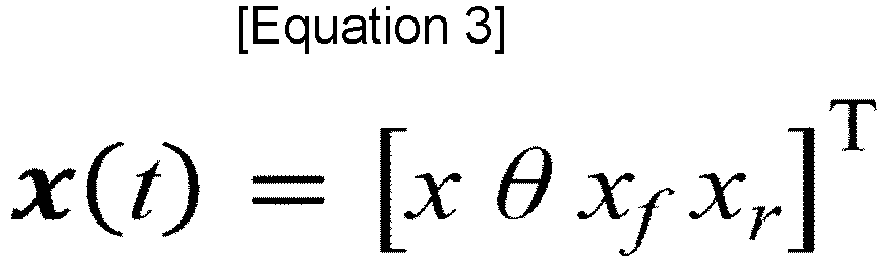
- The matrices M, C, and K are given by the following Equations (4) to (6), respectively, and are quantities depending on parameters.


- The right side of the Equation (2) is given by a vector y representing the unevenness of the road surface and a matrix P depending on parameters. The matrix P is given by the following Equation (7), and the vector y is given by the following Equation (8).


- In the following description, as expressed in Equation (9), twelve state variables are represented by a vector Xa.

- The road surface
profile estimating device 10 represents, with a noise term, an error that may occur by modeling a behavior of thevehicle 30 by using the half car model. The road surfaceprofile estimating device 10 obtains the time evolution of the state variable Xa according to the following Equation (10).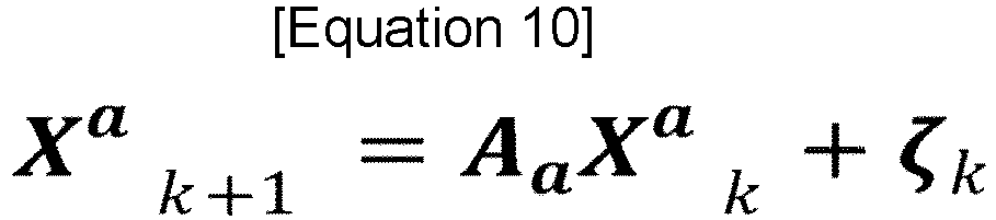
- Here, the subscripts "k" and "k+1" of the state variable Xa represent time steps. The matrix Aa on the right side represents the time evolution of the state variable expressed by Equation (2) as linear transform in a unit time step. When Aa is represented by exp(AcaΔt), Aca is expressed by the following Equation (11). However, Δt represents a unit time step.

- Here, Ac is expressed by the following Equation (12), and Bc is expressed by the following Equation (13). 0m×n is an m×n matrix of which all elements are 0.


- Here, the matrices M, C, K, and P are as expressed in Equations (4) to (7). I4×4 is a unit matrix of 4×4, and the matrices O4x4, O4×2, and O2×2 are zero matrices of 4×4, 4×2, and 2×2, respectively.
- ζk on the right side of Equation (10) is a noise term at the time step k. The noise term ζk includes an eight-dimensional vector wk and a four-dimensional vector ηk as expressed by the following Equation (14).

- In the noise term ζk, the noise term wk for the vertical displacement x and velocity dx/dt of the center of gravity of the half car model, the vertical displacement xf and velocity dxf/dt of the front suspension of the half car model, the vertical displacement xr and velocity dxr/dt of the rear suspension of the half car model, and the rotation angle θ and the angular velocity dθ/dt with respect to the pitch axis passing through the center of gravity of the half car model is the Gaussian noise having an average of 0 and a variance-covariance matrix of Q. The variance-covariance matrix of the noise term wk is expressed by the following Equation (15). Here, δk,l is a Kronecker delta.

- In the noise term ζk, the noise term ηk for the vertical displacement yf and velocity dyf/dt of the front tire of the half car model and the vertical displacement yr and velocity dyr/dt of the rear tire of the half car model is the Gaussian noise having an average of 0 and a variance-covariance matrix of S. The variance-covariance matrix of the noise term ηk is expressed by the following Equation (16).

- The road surface
profile estimating device 10 calculates an acceleration, an angular velocity, a displacement, and an angular displacement from the state variables predicted by theprediction unit 12 on the basis of the observation model M2 (S113). The road surfaceprofile estimating device 10 calculates a vector u that summarizes the acceleration, the angular velocity, the displacement, and the angular displacement from the state variable Xa predicted by theprediction unit 12 on the basis of the observation model M2 expressed by the following Equation (17). The road surfaceprofile estimating device 10 models the observation through linear transform Ca of the state variables, and models an observation error by using a noise term vk.
- Here, the linear transform Ca is given by the following Equation (18).

- The matrix C1 is given by the following Equation (19).

- The noise term vk on the right side of Equation (17) is the Gaussian noise having an average of 0 and a variance-covariance matrix of R. The variance-covariance matrix of the noise term vk is expressed by the following Equation (20).

- The road surface
profile estimating device 10 updates the state variable by using an optimum Kalman gain (S114). Here, the optimum Kalman gain is an update coefficient determined to minimize a square error of the state variable, and is given by the following Equation (21).
- Pk+1 - on the right side of Equation (21) is a variance of the state variable before update at the time step k+1. Regarding the state variables, an initial value of an expected value is given by the following Equation (22), and an initial value of the variance is given by the following Equation (23). The state variable Xa with the hat symbol represents an estimated value.


- As described above, the time evolution of the expected value of the state variable Xa is given by the following Equation (24).

- Here, the superscript "-" indicates an amount before the update. The time evolution of the variance of the state variable Xa is given by the following Equation (25).

- The
update unit 14 obtains an expected value of the updated state variable Xa according to the following Equation (26).
- Here, uk+1 on the right side is a value observed at the time step k+1. The second term on the right side is a term for correcting the state variable by using a value obtained by multiplying an observation residual by the optimum Kalman gain Gk+1.
- The road surface
profile estimating device 10 obtains a variance of the updated state variable Xa by using the following Equation (27).
- As described above, state variables can be estimated with high accuracy by predicting the state variables for each time step and updating the state variables according to a measurement residual. In the present embodiment, the simulation model M1 is a model that represents the time evolution of the state variables by using the linear transform of the state variable and the Gaussian noise, and the observation model M2 is a model used to calculate observation values of physical quantities by using the linear transform of the state variable and the Gaussian noise. The
update unit 14 of the road surfaceprofile estimating device 10 according to the present embodiment may update the state variables such that a square error of the state variables is minimized. That is, the road surfaceprofile estimating device 10 may update the state variables by using the optimum Kalman gain. As described above, the time evolution of the state variables is represented by the simulation model M1 including the linear transform and the Gaussian noise, and the observation is represented by the observation model M2 including the linear transform and the Gaussian noise, and thus a road surface profile can be estimated through computation causing a relatively low load. - The road surface
profile estimating device 10 smooths state variables on the basis of a gain of backpropagation (S115). In the road surfaceprofile estimating device 10 according to the present embodiment, the state variables are smoothed by using an RTS smoothing method. Specifically, when the time step exists from k=0 to k=T, the road surfaceprofile estimating device 10 may use all subsequent state variables xk+1, xk+2, ..., and xT in order to smooth a state variable xk at the time step k. However, an interval L (where L is any natural number) may be designated, and the state variables may be smoothed by using xk+1, xk+2, ..., and xk+L. - The road surface
profile estimating device 10 initializes an expected value of the smoothed state variable by using the following Equation (28), and initializes a variance of the smoothed state variable by using the following Equation (29). Here, the superscript "RTS" of the state variable Xa indicates that a value is RTS smoothed.

- Next, the road surface
profile estimating device 10 calculates a gain φ of the backpropagation in the smoothing process by using the following Equation (30).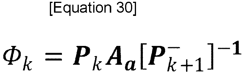
- The road surface
profile estimating device 10 smooths the expected value of the state variable from the time step k=T toward the past by using the following Equation (31) on the basis of the gain φ. The road surfaceprofile estimating device 10 smooths the variance of the state variables by using the following Equation (32).

- As described above, the state variables are smoothed. As described above, not only the vertical acceleration and the angular velocity with respect to the pitch axis but also the vertical displacement and the angular displacement with respect to the pitch axis are used for data smoothing, and thus a road surface profile can be estimated more accurately.
- Thereafter, the
update unit 14 of the road surfaceprofile estimating device 10 updates the variance-covariance matrix Q of noise added to the state variables in the simulation model M1 and the variance-covariance matrix R of noise added to the observation values of the physical quantities in the observation model M2 on the basis of a difference between the physical quantities acquired by theacquisition unit 11 and the physical quantities calculated by the calculation unit 13 (S116). In the road surfaceprofile estimating device 10 according to the present embodiment, the variance-covariance matrix of noise is updated by using the Robbins-Monro algorithm. - Specifically, the road surface
profile estimating device 10 updates the variance-covariance matrix Q of noise added to the state variables in the simulation model M1 by using the following Equation (33). The road surfaceprofile estimating device 10 updates the variance-covariance matrix R of noise added to the observation values of the physical quantities in the observation model M2 by using the following Equation (34). In the present embodiment, the off-diagonal terms of Q and R are assumed to be 0, and the updates of Equations (34) and (35) are applied to the diagonal terms of Q and R.

- Here, uk - is a quantity expressed by the following Equation (35). αQ,k and αR,k are hyperparameters represented by positive real numbers smaller than 1, and may be, for example, about 1/7.

- As described above, the variance-covariance matrix Q of noise added to the state variables in the simulation model M1 and the variance-covariance matrix R of noise added to the observation values of the physical quantities in the observation model M2 are dynamically updated. Therefore, a road surface profile can be stably estimated by removing dependence on initial values of the variance-covariance matrices.
- Finally, the
estimation unit 15 of the road surfaceprofile estimating device 10 estimates a road surface profile on the basis of the variables representing the unevenness of the road surface and included in the state variables (S117). Specifically, the road surfaceprofile estimating device 10 estimates a road surface profile on the basis of the vertical displacement yf of the front tire of the half car model and the vertical displacement yr of the rear tire of the half car model. Thus, the road surface profile estimation process is finished. -
Fig. 7 is a diagram illustrating parameters determined by the road surfaceprofile estimating device 10 according to the first embodiment. In the present embodiment, the mass mf of the front tire, the mass mr of the rear tire, the damping coefficient cf of the front suspension, the damping coefficient cr of the rear suspension, the spring coefficient kf of the front suspension, the spring coefficient kr of the rear suspension, the spring coefficient ktf of the front tire, the spring coefficient ktr of the rear tire of the half car model, the inertial moment Iz around the pitch axis of the vehicle body, and the horizontal distance Lf from the center of gravity of the half car model to the ground contact point of the front tire are determined. Among the parameters, the parameters other than the horizontal distance Lf from the center of gravity to the ground contact point of the front tire are expressed as a ratio to the total mass of the vehicle mtot=mH+mf+mr. - The table illustrated in
Fig. 7 indicates errors between the plurality of determined parameters and the true values in a case where the genetic algorithm for determining a plurality of parameters is executed a plurality of times. For example, focusing on the mass mf of the front tire, in a case of the first trial, the error is -18.4%, the error at the second trial is 5.1%, the error at the third trial is 26.4%, the error at the fourth trial is -40.0%, and the error at the fifth trial is -39.3%. As described above, it is a characteristic of the genetic algorithm that the values of the determined parameters differ depending on trial timings. In any trial case, a value of the evaluation function F is equal to or smaller than the threshold value. -
Fig. 8 is a diagram illustrating a power spectral density of the road surface profile estimated by the road surfaceprofile estimating device 10 according to the first embodiment. InFig. 8 , the vertical axis expresses a power spectral density (PSD) of the road surface profile estimated in the unit of m2/(cycle/m), and the horizontal axis expresses a frequency (Frequency) in the unit of cycle/m. The vertical axis and the horizontal axis are logarithmic axes. - In
Fig. 8 , a spectral density calculated from a true road surface profile is indicated by a solid line, a spectral density calculated by using the parameters at the first trial illustrated inFig. 7 is indicated by a dashed line, a spectral density calculated by using the parameters at the fourth trial illustrated inFig. 7 is indicated by a dot chain line, and a spectral density calculated by using the parameters at the fifth trial illustrated inFig. 7 is indicated by a two-dot chain line. - According to
Fig. 8 , the spectral densities calculated by using the parameters at the first and fourth trials are almost consistent with the spectral density calculated from the true road surface profile in the entire frequency domain. On the other hand, the spectral density calculated by using the parameters at the fifth trial is different from the spectral density calculated from the true road surface profile, especially in the high frequency domain. - The
determination unit 16 of the road surfaceprofile estimating device 10 according to the present embodiment may perform regression analysis in which a logarithm of a power spectral density calculated by using the candidate values for a plurality of parameters is used as a dependent variable and a logarithm of a frequency is used as an independent variable, and may determine whether or not to employ the candidate values on the basis of comparison between the determination coefficient in the regression analysis and the threshold value. For example, the spectral density calculated by using the parameters at the fifth trial deviates from the straight line on the double-logarithmic graph, and the determination coefficient in the regression analysis is equal to or less than the threshold value. Thus, thedetermination unit 16 may not employ the parameters at the fifth trial. As described above, a plurality of parameters can be determined more accurately. -
Fig. 9 is a diagram illustrating a road surface profile estimated for the front tire and a road surface profile estimated for the rear tire by the road surfaceprofile estimating device 10 according to the first embodiment. InFig. 9 , the vertical axis expresses a road surface profile in the unit of meter (m), and the horizontal axis expresses a traveling distance (Distance) in the unit of meter (m). InFig. 9 , a medium-sized vehicle (Medium) is used as thevehicle 30, a road surface profile estimated for the front tire by the road surfaceprofile estimating system 1 according to the present embodiment is indicated by a solid line, and a road surface profile estimated for the rear tire is indicated by a dot chain line. - The road surface
profile estimating device 10 according to the present embodiment determines a plurality of parameters P of the simulation model M1 such that the integration of the power spectral density of the road surface profile related to the front tire matches the integration of the power spectral density of the road surface profile related to the rear tire. According toFig. 9 , it can be confirmed that the road surface profiles estimated by using the parameters P determined in the above-described way substantially match each other for the front tire and the rear tire. -
Fig. 10 is a diagram illustrating a power spectral density of a road surface profile estimated for the front tire and a power spectral density of a road surface profile estimated for the rear tire by the road surfaceprofile estimating device 10 according to the first embodiment. InFig. 10 , the vertical axis expresses a power spectral density (PSD) of the road surface profile estimated in the unit of m2/(cycle/m), and the horizontal axis expresses a frequency (Frequency) in the unit of cycle/m. The vertical axis and the horizontal axis are logarithmic axes. - The road surface
profile estimating device 10 according to the present embodiment determines a plurality of parameters P of the simulation model M1 such that the integration of the power spectral density of the road surface profile related to the front tire matches the integration of the power spectral density of the road surface profile related to the rear tire. According toFig. 10 , it can be confirmed that the power spectral densities of the road surface profiles calculated by using the parameters P determined in the above-described way substantially match each other for the front tire and the rear tire. -
Fig. 11 is a diagram illustrating a relationship between an IRI of the road surface estimated by the road surfaceprofile estimating device 10 according to the first embodiment and a distance. InFig. 11 , the vertical axis expresses a road surface profile in the unit of meter (m), and the horizontal axis expresses a traveling distance (Distance) in the unit of meter (m). InFig. 11 , an IRI calculated by the road surfaceprofile estimating system 1 according to the present embodiment by using a medium-sized vehicle (Medium) is indicated by a solid line, an IRI calculated by the road surfaceprofile estimating system 1 according to the present embodiment by using a light vehicle (Light) is indicated by a dot chain line, an IRI calculated by the road surfaceprofile estimating system 1 according to the present embodiment by using a large vehicle (Heavy) is indicated by a dashed line, and an IRI measured by using a dedicated vehicle (Profiler) is indicated by a two-dot chain line. - According to
Fig. 11 , regardless of whether the light vehicle, the medium-sized vehicle, or the large vehicle is used as thevehicle 30, it can be confirmed that the substantially same result as the IRI measured by using the dedicated vehicle is obtained by the road surfaceprofile estimating system 1 according to the present embodiment. As described above, the road surfaceprofile estimating device 10 requests that the power spectral densities of the estimated road surface profiles match each other for the front tire and the rear tire even in a case where a plurality of parameters for modeling thevehicle 30 are unknown, and can thus appropriately determine a plurality of parameters and estimate a road surface profile with high accuracy. -
Fig. 12 is a diagram illustrating a relationship between a velocity and a distance of a vehicle used for estimating an IRI of the road surface by the road surfaceprofile estimating device 10 according to the first embodiment. InFig. 12 , the vertical axis expresses a velocity of thevehicle 30 in the unit of kilometer per hour (km/h), and the horizontal axis expresses a traveling distance (Distance) in the unit of kilometer (km). InFig. 12 , a velocity of a medium-sized vehicle (Medium) is indicated by a solid line, a velocity of a light vehicle (Light) is indicated by a dot chain line, and a velocity of a large vehicle (Heavy) is indicated by a dashed line. It can be seen fromFig. 12 that velocities of the medium-sized vehicle, the light vehicle, and the large vehicle are not constant, and temporal changes of the velocities are also different from each other. As described above, even if the velocities of thevehicles 30 used for measuring the acceleration and the angular velocity are different, the road surfaceprofile estimating system 1 according to the present embodiment can appropriately determine a plurality of parameters P included in the simulation model M1 and can stably estimate a road surface profile. The road surfaceprofile estimating system 1 according to the present embodiment can estimate a road surface profile with high accuracy regardless of a size or a traveling velocity of thevehicle 30 provided with thesmartphone 20 having theaccelerometer 21 and theangular velocity meter 22 built therein. - The road surface
profile estimating device 10 according to the present embodiment has the same functions as those of the road surfaceprofile estimating device 10 according to the first embodiment except that a different process is performed by thedetermination unit 16. Thedetermination unit 16 of the road surfaceprofile estimating device 10 according to the present embodiment determines a plurality of parameters P such that an absolute value of an evaluation function including a difference between a first function calculated from variables representing a vertical displacement and velocity of the front tire and a second function calculated from variables representing a vertical displacement and velocity of the rear tire is small. Here, the first function is a value yf(y) of variables representing the vertical displacement of the front tire at a predetermined time point t, and the second function is a value yr(t+L/v(t)) of variables representing the vertical displacement of the rear tire at a time point (t+L/v(t)) obtained by adding, to the predetermined time point, a value that is obtained by dividing a distance L (=Lf+Lr) from the front tire to the rear tire by a velocity v(t) of thevehicle 30 at the predetermined time point t. Here, the velocity v(t) of thevehicle 30 may be a value measured by a speedometer provided in thevehicle 30 or a value measured on the basis of GPS position information. The evaluation function F may be expressed by the following Equation (36), for example.
- Here, t represents time, and ta and tb represent the lower and upper limit times of integration. The road surface
profile estimating device 10 determines whether or not to employ candidate values for a plurality of parameters depending on whether or not a value of the evaluation function F is equal to or smaller than a threshold value. The threshold value may be freely set, and may be, for example, about 10-4. - As described above, it is corrected that the variable representing the vertical displacement of the front tire and the variable representing the vertical displacement of the rear tire are estimated to deviate by a wheelbase length, and thus a plurality of parameters P included in the simulation model M1 can be determined.
-
Fig. 13 is a flowchart illustrating a parameter determination process executed by the road surfaceprofile estimating device 10 according to the second embodiment of the present invention. First, the road surfaceprofile estimating device 10 sets candidate values for a plurality of parameters P included in the simulation model M1 (S20). - The road surface
profile estimating device 10 estimates road surface profiles for the front tire and the rear tire by using the set candidate values for the parameters P (S21). Details of the process of estimating the road surface profiles are the same as those inFig. 6 . - Thereafter, the road surface
profile estimating device 10 calculates the value yf(y) of the variable representing the vertical displacement of the front tire and the value yr(t+L/v(t)) of the variable representing the vertical displacement of the rear tire, obtained by correcting a delay of the wheelbase length, and determines whether or not a difference between the road surface profiles is equal to or less than a threshold value (S22). That is, the road surfaceprofile estimating device 10 determines whether a value of the evaluation function F expressed by Equation (36) is equal to or smaller than the threshold value. - In a case where the value of the evaluation function F is not equal to or smaller than the threshold value (S22: NO), the road surface
profile estimating device 10 executes selection, crossover, and mutation processes on the plurality of parameters P, and thus sets new candidate values (S23). The new candidate values for the parameters are used to repeatedly perform estimation of road surface profiles (S21) and comparison between a value of the evaluation function F and the threshold value (S22). Here, the selection, crossover, and mutation processes may be processes used in an existing genetic algorithm. A plurality of parameters P are determined by using the genetic algorithm, and thus appropriate parameters P can be efficiently determined even in a case where the number of the plurality of parameters P increases and a complete search is difficult. - On the other hand, in a case where the value of the evaluation function F is equal to or smaller than the threshold value (S22: YES), the road surface
profile estimating device 10 determines the calculated parameters as a plurality of parameters P of the simulation model M1 (S24). Thus, the parameter determination process is finished. - The road surface
profile estimating device 10 according to the present embodiment has the same functions as those of the road surfaceprofile estimating device 10 according to the first embodiment except that a different process is performed by thedetermination unit 16. Thedetermination unit 16 of the road surfaceprofile estimating device 10 according to the present embodiment determines a plurality of parameters P such that an absolute value of an evaluation function for evaluating a difference between a road surface profile estimated under a first condition and a road surface profile estimated under a second condition is small. Here, the road surface profile estimated under the first condition is a road surface profile estimated by theestimation unit 15 in a case where thevehicle 30 has traveled on a predetermined road at a first velocity v1, and the road surface profile estimated under the second condition is a road surface profile estimated by theestimation unit 15 in a case where thevehicle 30 has traveled on the predetermined road at a second velocity v2 different from the first velocity v1. Here, the first velocity v1 and the second velocity v2 may be time-dependent values, respectively. The first velocity v1 and the second velocity v2 may be values measured by a speedometer provided in thevehicle 30, or may be values measured on the basis of GPS position information. The road surfaceprofile estimating device 10 according to the present embodiment can determine a plurality of parameters P included in the simulation model M1 under the request that the road surface profile estimated in a case where the vehicle has traveled on a predetermined road at the first velocity v1 and the road surface profile estimated in a case where the vehicle has traveled on the predetermined road at the second velocity v2 are required to match each other. - The evaluation function F may be used to evaluate a difference between an international roughness index IRIv1 of the road surface profile estimated under the first condition and an international roughness index IRIv2 of the road surface profile estimated under the second condition. The evaluation function F may be expressed by the following Equation (37), for example.
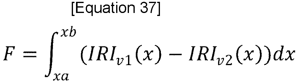
- Here, x represents a distance, and xa and xb represent the lower and upper limit times of integration. The road surface
profile estimating device 10 determines whether or not to employ candidate values for a plurality of parameters depending on whether or not a value of the evaluation function F is equal to or smaller than a threshold value. The threshold value may be freely set, and may be, for example, about 10-4. - As described above, the international roughness indexes are calculated on the basis of the road surface profiles estimated under the first condition and the second condition, and the plurality of parameters P included in the simulation model M1 are determined such that a difference between the international roughness indexes estimated under both conditions is reduced. Therefore, it is possible to determine the plurality of parameters P included in the simulation model M1 together with the estimation of the road surface profiles.
-
Fig. 14 is a flowchart illustrating a parameter determination process executed by the road surfaceprofile estimating device 10 according to the third embodiment of the present invention. First, the road surfaceprofile estimating device 10 sets candidate values for a plurality of parameters P included in the simulation model M1 (S30). - The road surface
profile estimating device 10 estimates road surface profiles in a case where the vehicle has traveled at a first velocity and a case where the vehicle has traveled at a second velocity by using the set candidate values for the parameters P (S31). Details of the process of estimating the road surface profiles are the same as those inFig. 6 . - Thereafter, the road surface
profile estimating device 10 calculates IRIv1 in a case where the vehicle has traveled at the first velocity and IRIv2 in a case where the vehicle has traveled at the second velocity (S32). The road surfaceprofile estimating device 10 determines whether a difference between the IRIs is equal to or less than a threshold value (S33). That is, the road surfaceprofile estimating device 10 determines whether a value of the evaluation function F expressed by Equation (37) is equal to or smaller than the threshold value. - In a case where the value of the evaluation function F is not equal to or smaller than the threshold value (S33: NO), the road surface
profile estimating device 10 executes selection, crossover, and mutation processes on the plurality of parameters P, and thus sets new candidate values (S33). The new candidate values for the parameters are used to repeatedly perform estimation of road surface profiles (S31), calculation of IRIs (S32), and comparison between a value of the evaluation function F and the threshold value (S33). Here, the selection, crossover, and mutation processes may be processes used in an existing genetic algorithm. A plurality of parameters P are determined by using the genetic algorithm, and thus appropriate parameters P can be efficiently determined even in a case where the number of the plurality of parameters P increases and a complete search is difficult. - On the other hand, when the value of the evaluation function F is equal to or smaller than the threshold value (S33: YES), the road surface
profile estimating device 10 determines the calculated parameters as a plurality of parameters P of the simulation model M1 (S35). Thus, the parameter determination process is finished. - The embodiments described above are for facilitating the understanding of the present invention, and are not for limiting the interpretation of the present invention. Each element included in the embodiment and its disposition, material, condition, shape, size, and the like are not limited to those exemplified, and may be changed as appropriate. The constituents described in the different embodiments may be partially replaced or combined.
-
- 1
- road surface profile estimating system
- 10
- road surface profile estimating device
- 10a
- CPU
- 10b
- RAM
- 10c
- ROM
- 10d
- communication unit
- 10e
- input unit
- 10f
- display unit
- 11
- acquisition unit
- 12
- prediction unit
- 13
- calculation unit
- 14
- update unit
- 15
- estimation unit
- 16
- determination unit
- 17
- storage unit
- 20
- smartphone
- 21
- accelerometer
- 22
- angular velocity meter
- M1
- simulation model
- M2
- observation model
- N
- communication network
- P
- parameter
Claims (13)
- A road surface profile estimating device comprising:an acquisition unit configured to acquire physical quantities representing a motion of a vehicle that is traveling on a road surface;a prediction unit configured to predict time evolution of state variables including variables representing an unevenness of the road surface on which the vehicle is traveling and variables representing the physical quantities on the basis of a simulation model including a plurality of parameters;a calculation unit configured to calculate observation values of the physical quantities from the state variables predicted by the prediction unit on the basis of an observation model;an update unit configured to update the state variables through data assimilation between the physical quantities acquired by the acquisition unit and the physical quantities calculated by the calculation unit;an estimation unit configured to estimate respective profiles of the road surface under a first condition and a second condition on the basis of the variable representing the unevenness of the road surface, included in the state variables; anda determination unit configured to determine the plurality of parameters such that an absolute value of an evaluation function for evaluating a difference between the profile of the road surface estimated under the first condition and the profile of the road surface estimated under the second condition is small.
- The road surface profile estimating device according to claim 1, wherein
the update unit updates a variance-covariance matrix of noise added to the state variables in the simulation model and a variance-covariance matrix of noise added to the observation values of the physical quantities in the observation model on the basis of a difference between the physical quantities acquired by the acquisition unit and the physical quantities calculated by the calculation unit. - The road surface profile estimating device according to claim 1 or 2, whereinthe simulation model is a half car model for the vehicle,the profile of the road surface estimated under the first condition is a profile of the road surface estimated on the basis of variables representing a vertical displacement and velocity of a front tire of the half car model,the profile of the road surface estimated under the second condition is a profile of the road surface estimated on the basis of variables representing a vertical displacement and velocity of a rear tire of the half car model, andthe evaluation function includes a difference between a first function calculated from the variables representing the vertical displacement and velocity of the front tire and a second function calculated from the variables representing the vertical displacement and velocity of the rear tire.
- The road surface profile estimating device according to claim 3, whereinthe first function is a power spectral density of the profile of the road surface calculated from the variables representing the vertical displacement and velocity of the front tire, andthe second function is a power spectral density of the profile of the road surface calculated from the variables representing the vertical displacement and velocity of the rear tire.
- The road surface profile estimating device according to claim 4, wherein
the determination unit performs regression analysis in which a logarithm of the power spectral density calculated by using candidate values for the plurality of parameters is used as a dependent variable and a logarithm of a frequency is used as an independent variable, and determines whether or not to employ the candidate values on the basis of comparison between a determination coefficient in the regression analysis and a threshold value. - The road surface profile estimating device according to claim 3, whereinthe first function is a value of variables representing a vertical displacement of the front tire at a predetermined time point, andthe second function is a value of variables representing a vertical displacement of the rear tire at a time point obtained by adding, to the predetermined time point, a value that is obtained by dividing a distance from the front tire to the rear tire by a velocity of the vehicle at the predetermined time point.
- The road surface profile estimating device according to any one of claims 1 to 3, whereinthe profile of the road surface estimated under the first condition is a profile of the road surface estimated by the estimation unit in a case where the vehicle has traveled on a predetermined road at a first velocity, andthe profile of the road surface estimated under the second condition is a profile of the road surface estimated by the estimation unit in a case where the vehicle has traveled on the predetermined road at a second velocity different from the first velocity.
- The road surface profile estimating device according to claim 7, wherein
the evaluation function is used to evaluate a difference between an international roughness index of the profile of the road surface estimated under the first condition and an international roughness index of the profile of the road surface estimated under the second condition. - The road surface profile estimating device according to any one of claims 1 to 8, wherein
the determination unit determines the plurality of parameters by using a genetic algorithm. - The road surface profile estimating device according to any one of claims 1 to 9, whereinthe simulation model is a model representing the time evolution of the state variables by using linear transform of the state variables and Gaussian noise,the observation model is a model for calculating the observation values of the physical quantities by using the linear transform of the state variables and the Gaussian noise, andthe update unit updates the state variables such that a square error of the state variables is minimized.
- A road surface profile estimating system comprising:a vehicle configured to travel on a road surface;a measurement unit configured to measure physical quantities representing a motion of the vehicle; anda road surface profile estimating device configured to estimate a profile of the road surface on which the vehicle is traveling, whereinthe road surface profile estimating device includesa prediction unit configured to predict time evolution of state variables including variables representing an unevenness of the road surface on which the vehicle is traveling and variables representing the physical quantities on the basis of a simulation model including a plurality of parameters,a calculation unit configured to calculate observation values of the physical quantities from the state variables predicted by the prediction unit on the basis of an observation model,an update unit configured to update the state variables through data assimilation between the physical quantities measured by the measurement unit and the physical quantities calculated by the calculation unit,an estimation unit configured to estimate respective profiles of the road surface under a first condition and a second condition on the basis of the variables representing the unevenness of the road surface, included in the state variables, anda determination unit configured to determine the plurality of parameters such that a difference between a first characteristic value representing a characteristic of the profile of the road surface estimated under the first condition and a second characteristic value representing a characteristic of the profile of the road surface estimated under the second condition is small.
- A road surface profile estimating method comprising:acquiring physical quantities representing a motion of a vehicle that is traveling on a road surface;predicting time evolution of state variables including variables representing an unevenness of the road surface on which the vehicle is traveling and variables representing the physical quantities on the basis of a simulation model including a plurality of parameters;calculating observation values of the physical quantities from the predicted state variables on the basis of an observation model;updating the state variables through data assimilation between the acquired physical quantities and the calculated physical quantities;estimating respective profiles of the road surface under a first condition and a second condition on the basis of the variables representing the unevenness of the road surface, included in the state variables; anddetermining the plurality of parameters such that a difference between a first characteristic value representing a characteristic of the profile of the road surface estimated under the first condition and a second characteristic value representing a characteristic of the profile of the road surface estimated under the second condition is small.
- A road surface profile estimating program causing a computation unit provided in a road surface profile estimating device to function as:an acquisition unit configured to acquire physical quantities representing a motion of a vehicle that is traveling on a road surface;a prediction unit configured to predict time evolution of state variables including variables representing an unevenness of the road surface on which the vehicle is traveling and variables representing the physical quantities on the basis of a simulation model including a plurality of parameters;a calculation unit configured to calculate observation values of the physical quantities from the state variables predicted by the prediction unit on the basis of an observation model;an update unit configured to update the state variables through data assimilation between the physical quantities acquired by the acquisition unit and the physical quantities calculated by the calculation unit;an estimation unit configured to estimate respective profiles of the road surface under a first condition and a second condition on the basis of the variables representing the unevenness of the road surface, included in the state variables; anda determination unit configured to determine the plurality of parameters such that a difference between a first characteristic value representing a characteristic of the profile of the road surface estimated under the first condition and a second characteristic value representing a characteristic of the profile of the road surface estimated under the second condition is small.
Applications Claiming Priority (2)
| Application Number | Priority Date | Filing Date | Title |
|---|---|---|---|
| JP2018213088 | 2018-11-13 | ||
| PCT/JP2019/044051 WO2020100784A1 (en) | 2018-11-13 | 2019-11-11 | Road surface profile estimating device, road surface profile estimating system, road surface profile estimating method, and road surface profile estimating program |
Publications (3)
| Publication Number | Publication Date |
|---|---|
| EP3882880A1 true EP3882880A1 (en) | 2021-09-22 |
| EP3882880A4 EP3882880A4 (en) | 2022-08-24 |
| EP3882880B1 EP3882880B1 (en) | 2024-03-20 |
Family
ID=70730813
Family Applications (1)
| Application Number | Title | Priority Date | Filing Date |
|---|---|---|---|
| EP19883588.6A Active EP3882880B1 (en) | 2018-11-13 | 2019-11-11 | Road surface profile estimating device, road surface profile estimating system, road surface profile estimating method, and road surface profile estimating program |
Country Status (5)
| Country | Link |
|---|---|
| EP (1) | EP3882880B1 (en) |
| JP (1) | JP7390731B2 (en) |
| CN (1) | CN112997225B (en) |
| ES (1) | ES2980219T3 (en) |
| WO (1) | WO2020100784A1 (en) |
Cited By (2)
| Publication number | Priority date | Publication date | Assignee | Title |
|---|---|---|---|---|
| US20220412756A1 (en) * | 2021-06-25 | 2022-12-29 | Toyota Jidosha Kabushiki Kaisha | Information processing apparatus, information processing method, and storage medium |
| FR3128178A1 (en) * | 2021-10-20 | 2023-04-21 | Continental Automotive Gmbh | Method for predicting a surface condition of a road segment |
Families Citing this family (2)
| Publication number | Priority date | Publication date | Assignee | Title |
|---|---|---|---|---|
| CN113353085B (en) * | 2021-07-03 | 2023-03-21 | 西北工业大学 | Road surface unevenness identification method based on Kalman filtering theory |
| JP7478181B2 (en) * | 2022-03-31 | 2024-05-02 | カヤバ株式会社 | Calculation device, calculation method, and program |
Family Cites Families (16)
| Publication number | Priority date | Publication date | Assignee | Title |
|---|---|---|---|---|
| US5065618A (en) * | 1990-11-14 | 1991-11-19 | Hodges Transportation Inc. | Method and apparatus for determining terrain surface profiles |
| JPH0755469A (en) * | 1993-08-11 | 1995-03-03 | Nippon Telegr & Teleph Corp <Ntt> | Multi-view stereo image measurement method |
| JP2004110590A (en) | 2002-09-19 | 2004-04-08 | Natl Inst For Land & Infrastructure Management Mlit | A method for generating an evaluation model of a bicycle road surface condition, a bicycle road surface environment evaluation method, and an evaluation system |
| JP4262133B2 (en) * | 2004-04-27 | 2009-05-13 | 独立行政法人科学技術振興機構 | Driving simulator |
| JP4727473B2 (en) | 2006-03-23 | 2011-07-20 | 株式会社豊田中央研究所 | Optimal parameter search method and program thereof |
| JP5151161B2 (en) * | 2007-01-29 | 2013-02-27 | トヨタ自動車株式会社 | Vehicle state estimation device and shock absorber control device |
| JP2010060489A (en) | 2008-09-05 | 2010-03-18 | Seiko Epson Corp | Satellite orbital modeling propriety determination method, long term prediction orbital data supply method, and satellite orbital modeling propriety determination device |
| JP5563796B2 (en) | 2009-09-25 | 2014-07-30 | トヨタ自動車株式会社 | Pedestrian movement estimation apparatus and method |
| JP5502448B2 (en) * | 2009-12-17 | 2014-05-28 | 富士重工業株式会社 | Road surface shape recognition device |
| CN102222141B (en) * | 2011-06-10 | 2012-12-19 | 中国汽车工程研究院股份有限公司 | Method for generation of typical road spectrum |
| JP6127560B2 (en) * | 2013-02-13 | 2017-05-17 | 日産自動車株式会社 | Road shape prediction device |
| JP6132304B2 (en) | 2013-07-31 | 2017-05-24 | 国立大学法人 東京大学 | Road surface evaluation apparatus and method |
| JP2017053777A (en) * | 2015-09-10 | 2017-03-16 | 株式会社日立製作所 | Road surface measuring system, and road surface measuring method |
| WO2017064734A1 (en) * | 2015-10-16 | 2017-04-20 | Politecnico Di Bari | Method for determining the modal parameters of road or rail vehicles and for the indirect characterization of road or rail profiles |
| JP6610770B2 (en) | 2016-03-11 | 2019-11-27 | 富士通株式会社 | Wiebe function parameter identification apparatus, method and program |
| JP6842112B2 (en) * | 2017-04-27 | 2021-03-17 | 国立大学法人 東京大学 | Road surface profile estimation device, road surface profile estimation system, road surface profile estimation method and road surface profile estimation program |
-
2019
- 2019-11-11 WO PCT/JP2019/044051 patent/WO2020100784A1/en not_active Ceased
- 2019-11-11 CN CN201980074254.9A patent/CN112997225B/en active Active
- 2019-11-11 ES ES19883588T patent/ES2980219T3/en active Active
- 2019-11-11 JP JP2020555667A patent/JP7390731B2/en active Active
- 2019-11-11 EP EP19883588.6A patent/EP3882880B1/en active Active
Cited By (4)
| Publication number | Priority date | Publication date | Assignee | Title |
|---|---|---|---|---|
| US20220412756A1 (en) * | 2021-06-25 | 2022-12-29 | Toyota Jidosha Kabushiki Kaisha | Information processing apparatus, information processing method, and storage medium |
| US12281908B2 (en) * | 2021-06-25 | 2025-04-22 | Toyota Jidosha Kabushiki Kaisha | Information processing apparatus, information processing method, and storage medium |
| FR3128178A1 (en) * | 2021-10-20 | 2023-04-21 | Continental Automotive Gmbh | Method for predicting a surface condition of a road segment |
| WO2023066710A1 (en) * | 2021-10-20 | 2023-04-27 | Continental Automotive Gmbh | Method for predicting a surface condition of a road segment |
Also Published As
| Publication number | Publication date |
|---|---|
| EP3882880B1 (en) | 2024-03-20 |
| JPWO2020100784A1 (en) | 2021-09-30 |
| CN112997225B (en) | 2023-02-03 |
| CN112997225A (en) | 2021-06-18 |
| JP7390731B2 (en) | 2023-12-04 |
| ES2980219T3 (en) | 2024-09-30 |
| WO2020100784A1 (en) | 2020-05-22 |
| EP3882880A4 (en) | 2022-08-24 |
Similar Documents
| Publication | Publication Date | Title |
|---|---|---|
| EP3882880B1 (en) | Road surface profile estimating device, road surface profile estimating system, road surface profile estimating method, and road surface profile estimating program | |
| Liu et al. | Large-scale pavement roughness measurements with vehicle crowdsourced data using semi-supervised learning | |
| EP3617647B1 (en) | Road surface profile estimating device, road surface profile estimating system, road surface profile estimating method, and road surface profile estimating program | |
| CN111806240B (en) | China working condition-based electric automobile driving range prediction method | |
| JP7079373B2 (en) | Tread wear monitoring system and method | |
| CN111152795A (en) | Model and parameter dynamic adjustment based adaptive vehicle state prediction system and prediction method | |
| CN109154498B (en) | Road monitoring method and system | |
| EP1792159B1 (en) | Method for calculating a friction-slippage curve for a tire | |
| CN112660112A (en) | Vehicle side-tipping state and side-tipping prediction method and system | |
| WO2016060161A1 (en) | Road surface state prediction method and road surface state prediction system | |
| JP2018501466A (en) | Scaleable vehicle model for indoor tire testing | |
| CN119953323B (en) | Vehicle control method and system in emergency braking scenario | |
| CN116278571A (en) | Vehicle control method, device, device and storage medium | |
| JP7595494B2 (en) | Wear amount estimation system, computation model generation system, and wear amount estimation method | |
| JP7409266B2 (en) | Rut determination device, rut determination method, program | |
| JP6260701B2 (en) | How to model tires in driving conditions at a given speed | |
| Wielitzka et al. | Credibility of state and friction coefficient estimation in vehicle dynamics using UKF | |
| CN115959143A (en) | Method for determining payload mass of vehicle | |
| Kim et al. | Estimation of lateral tire force from objective measurement data for handling analysis | |
| JP2025074521A (en) | Vehicle simulation method, computer program, and simulation device | |
| HK1260153A1 (en) | Road monitoring method and system |
Legal Events
| Date | Code | Title | Description |
|---|---|---|---|
| STAA | Information on the status of an ep patent application or granted ep patent |
Free format text: STATUS: THE INTERNATIONAL PUBLICATION HAS BEEN MADE |
|
| PUAI | Public reference made under article 153(3) epc to a published international application that has entered the european phase |
Free format text: ORIGINAL CODE: 0009012 |
|
| STAA | Information on the status of an ep patent application or granted ep patent |
Free format text: STATUS: REQUEST FOR EXAMINATION WAS MADE |
|
| 17P | Request for examination filed |
Effective date: 20210610 |
|
| AK | Designated contracting states |
Kind code of ref document: A1 Designated state(s): AL AT BE BG CH CY CZ DE DK EE ES FI FR GB GR HR HU IE IS IT LI LT LU LV MC MK MT NL NO PL PT RO RS SE SI SK SM TR |
|
| DAV | Request for validation of the european patent (deleted) | ||
| DAX | Request for extension of the european patent (deleted) | ||
| REG | Reference to a national code |
Ref country code: DE Ref legal event code: R079 Free format text: PREVIOUS MAIN CLASS: G08G0001000000 Ipc: G01C0007040000 Ref country code: DE Ref legal event code: R079 Ref document number: 602019048796 Country of ref document: DE Free format text: PREVIOUS MAIN CLASS: G08G0001000000 Ipc: G01C0007040000 |
|
| A4 | Supplementary search report drawn up and despatched |
Effective date: 20220721 |
|
| RIC1 | Information provided on ipc code assigned before grant |
Ipc: B60W 40/06 20120101ALI20220715BHEP Ipc: G01C 7/04 20060101AFI20220715BHEP |
|
| GRAP | Despatch of communication of intention to grant a patent |
Free format text: ORIGINAL CODE: EPIDOSNIGR1 |
|
| STAA | Information on the status of an ep patent application or granted ep patent |
Free format text: STATUS: GRANT OF PATENT IS INTENDED |
|
| INTG | Intention to grant announced |
Effective date: 20231016 |
|
| GRAS | Grant fee paid |
Free format text: ORIGINAL CODE: EPIDOSNIGR3 |
|
| GRAA | (expected) grant |
Free format text: ORIGINAL CODE: 0009210 |
|
| STAA | Information on the status of an ep patent application or granted ep patent |
Free format text: STATUS: THE PATENT HAS BEEN GRANTED |
|
| AK | Designated contracting states |
Kind code of ref document: B1 Designated state(s): AL AT BE BG CH CY CZ DE DK EE ES FI FR GB GR HR HU IE IS IT LI LT LU LV MC MK MT NL NO PL PT RO RS SE SI SK SM TR |
|
| REG | Reference to a national code |
Ref country code: GB Ref legal event code: FG4D |
|
| REG | Reference to a national code |
Ref country code: CH Ref legal event code: EP |
|
| REG | Reference to a national code |
Ref country code: IE Ref legal event code: FG4D |
|
| REG | Reference to a national code |
Ref country code: DE Ref legal event code: R096 Ref document number: 602019048796 Country of ref document: DE |
|
| PG25 | Lapsed in a contracting state [announced via postgrant information from national office to epo] |
Ref country code: LT Free format text: LAPSE BECAUSE OF FAILURE TO SUBMIT A TRANSLATION OF THE DESCRIPTION OR TO PAY THE FEE WITHIN THE PRESCRIBED TIME-LIMIT Effective date: 20240320 |
|
| REG | Reference to a national code |
Ref country code: LT Ref legal event code: MG9D |
|
| PG25 | Lapsed in a contracting state [announced via postgrant information from national office to epo] |
Ref country code: GR Free format text: LAPSE BECAUSE OF FAILURE TO SUBMIT A TRANSLATION OF THE DESCRIPTION OR TO PAY THE FEE WITHIN THE PRESCRIBED TIME-LIMIT Effective date: 20240621 |
|
| PG25 | Lapsed in a contracting state [announced via postgrant information from national office to epo] |
Ref country code: HR Free format text: LAPSE BECAUSE OF FAILURE TO SUBMIT A TRANSLATION OF THE DESCRIPTION OR TO PAY THE FEE WITHIN THE PRESCRIBED TIME-LIMIT Effective date: 20240320 Ref country code: RS Free format text: LAPSE BECAUSE OF FAILURE TO SUBMIT A TRANSLATION OF THE DESCRIPTION OR TO PAY THE FEE WITHIN THE PRESCRIBED TIME-LIMIT Effective date: 20240620 |
|
| REG | Reference to a national code |
Ref country code: NL Ref legal event code: MP Effective date: 20240320 |
|
| PG25 | Lapsed in a contracting state [announced via postgrant information from national office to epo] |
Ref country code: RS Free format text: LAPSE BECAUSE OF FAILURE TO SUBMIT A TRANSLATION OF THE DESCRIPTION OR TO PAY THE FEE WITHIN THE PRESCRIBED TIME-LIMIT Effective date: 20240620 Ref country code: NO Free format text: LAPSE BECAUSE OF FAILURE TO SUBMIT A TRANSLATION OF THE DESCRIPTION OR TO PAY THE FEE WITHIN THE PRESCRIBED TIME-LIMIT Effective date: 20240620 Ref country code: LT Free format text: LAPSE BECAUSE OF FAILURE TO SUBMIT A TRANSLATION OF THE DESCRIPTION OR TO PAY THE FEE WITHIN THE PRESCRIBED TIME-LIMIT Effective date: 20240320 Ref country code: HR Free format text: LAPSE BECAUSE OF FAILURE TO SUBMIT A TRANSLATION OF THE DESCRIPTION OR TO PAY THE FEE WITHIN THE PRESCRIBED TIME-LIMIT Effective date: 20240320 Ref country code: GR Free format text: LAPSE BECAUSE OF FAILURE TO SUBMIT A TRANSLATION OF THE DESCRIPTION OR TO PAY THE FEE WITHIN THE PRESCRIBED TIME-LIMIT Effective date: 20240621 Ref country code: FI Free format text: LAPSE BECAUSE OF FAILURE TO SUBMIT A TRANSLATION OF THE DESCRIPTION OR TO PAY THE FEE WITHIN THE PRESCRIBED TIME-LIMIT Effective date: 20240320 Ref country code: BG Free format text: LAPSE BECAUSE OF FAILURE TO SUBMIT A TRANSLATION OF THE DESCRIPTION OR TO PAY THE FEE WITHIN THE PRESCRIBED TIME-LIMIT Effective date: 20240320 |
|
| REG | Reference to a national code |
Ref country code: AT Ref legal event code: MK05 Ref document number: 1668177 Country of ref document: AT Kind code of ref document: T Effective date: 20240320 |
|
| PG25 | Lapsed in a contracting state [announced via postgrant information from national office to epo] |
Ref country code: SE Free format text: LAPSE BECAUSE OF FAILURE TO SUBMIT A TRANSLATION OF THE DESCRIPTION OR TO PAY THE FEE WITHIN THE PRESCRIBED TIME-LIMIT Effective date: 20240320 Ref country code: LV Free format text: LAPSE BECAUSE OF FAILURE TO SUBMIT A TRANSLATION OF THE DESCRIPTION OR TO PAY THE FEE WITHIN THE PRESCRIBED TIME-LIMIT Effective date: 20240320 |
|
| PG25 | Lapsed in a contracting state [announced via postgrant information from national office to epo] |
Ref country code: NL Free format text: LAPSE BECAUSE OF FAILURE TO SUBMIT A TRANSLATION OF THE DESCRIPTION OR TO PAY THE FEE WITHIN THE PRESCRIBED TIME-LIMIT Effective date: 20240320 |
|
| PG25 | Lapsed in a contracting state [announced via postgrant information from national office to epo] |
Ref country code: NL Free format text: LAPSE BECAUSE OF FAILURE TO SUBMIT A TRANSLATION OF THE DESCRIPTION OR TO PAY THE FEE WITHIN THE PRESCRIBED TIME-LIMIT Effective date: 20240320 |
|
| REG | Reference to a national code |
Ref country code: ES Ref legal event code: FG2A Ref document number: 2980219 Country of ref document: ES Kind code of ref document: T3 Effective date: 20240930 |
|
| PG25 | Lapsed in a contracting state [announced via postgrant information from national office to epo] |
Ref country code: IS Free format text: LAPSE BECAUSE OF FAILURE TO SUBMIT A TRANSLATION OF THE DESCRIPTION OR TO PAY THE FEE WITHIN THE PRESCRIBED TIME-LIMIT Effective date: 20240720 |
|
| PG25 | Lapsed in a contracting state [announced via postgrant information from national office to epo] |
Ref country code: SM Free format text: LAPSE BECAUSE OF FAILURE TO SUBMIT A TRANSLATION OF THE DESCRIPTION OR TO PAY THE FEE WITHIN THE PRESCRIBED TIME-LIMIT Effective date: 20240320 Ref country code: PT Free format text: LAPSE BECAUSE OF FAILURE TO SUBMIT A TRANSLATION OF THE DESCRIPTION OR TO PAY THE FEE WITHIN THE PRESCRIBED TIME-LIMIT Effective date: 20240722 |
|
| PG25 | Lapsed in a contracting state [announced via postgrant information from national office to epo] |
Ref country code: CZ Free format text: LAPSE BECAUSE OF FAILURE TO SUBMIT A TRANSLATION OF THE DESCRIPTION OR TO PAY THE FEE WITHIN THE PRESCRIBED TIME-LIMIT Effective date: 20240320 Ref country code: EE Free format text: LAPSE BECAUSE OF FAILURE TO SUBMIT A TRANSLATION OF THE DESCRIPTION OR TO PAY THE FEE WITHIN THE PRESCRIBED TIME-LIMIT Effective date: 20240320 |
|
| PG25 | Lapsed in a contracting state [announced via postgrant information from national office to epo] |
Ref country code: AT Free format text: LAPSE BECAUSE OF FAILURE TO SUBMIT A TRANSLATION OF THE DESCRIPTION OR TO PAY THE FEE WITHIN THE PRESCRIBED TIME-LIMIT Effective date: 20240320 |
|
| PG25 | Lapsed in a contracting state [announced via postgrant information from national office to epo] |
Ref country code: PL Free format text: LAPSE BECAUSE OF FAILURE TO SUBMIT A TRANSLATION OF THE DESCRIPTION OR TO PAY THE FEE WITHIN THE PRESCRIBED TIME-LIMIT Effective date: 20240320 |
|
| PG25 | Lapsed in a contracting state [announced via postgrant information from national office to epo] |
Ref country code: SK Free format text: LAPSE BECAUSE OF FAILURE TO SUBMIT A TRANSLATION OF THE DESCRIPTION OR TO PAY THE FEE WITHIN THE PRESCRIBED TIME-LIMIT Effective date: 20240320 |
|
| PG25 | Lapsed in a contracting state [announced via postgrant information from national office to epo] |
Ref country code: SM Free format text: LAPSE BECAUSE OF FAILURE TO SUBMIT A TRANSLATION OF THE DESCRIPTION OR TO PAY THE FEE WITHIN THE PRESCRIBED TIME-LIMIT Effective date: 20240320 Ref country code: SK Free format text: LAPSE BECAUSE OF FAILURE TO SUBMIT A TRANSLATION OF THE DESCRIPTION OR TO PAY THE FEE WITHIN THE PRESCRIBED TIME-LIMIT Effective date: 20240320 Ref country code: RO Free format text: LAPSE BECAUSE OF FAILURE TO SUBMIT A TRANSLATION OF THE DESCRIPTION OR TO PAY THE FEE WITHIN THE PRESCRIBED TIME-LIMIT Effective date: 20240320 Ref country code: PT Free format text: LAPSE BECAUSE OF FAILURE TO SUBMIT A TRANSLATION OF THE DESCRIPTION OR TO PAY THE FEE WITHIN THE PRESCRIBED TIME-LIMIT Effective date: 20240722 Ref country code: PL Free format text: LAPSE BECAUSE OF FAILURE TO SUBMIT A TRANSLATION OF THE DESCRIPTION OR TO PAY THE FEE WITHIN THE PRESCRIBED TIME-LIMIT Effective date: 20240320 Ref country code: IS Free format text: LAPSE BECAUSE OF FAILURE TO SUBMIT A TRANSLATION OF THE DESCRIPTION OR TO PAY THE FEE WITHIN THE PRESCRIBED TIME-LIMIT Effective date: 20240720 Ref country code: EE Free format text: LAPSE BECAUSE OF FAILURE TO SUBMIT A TRANSLATION OF THE DESCRIPTION OR TO PAY THE FEE WITHIN THE PRESCRIBED TIME-LIMIT Effective date: 20240320 Ref country code: CZ Free format text: LAPSE BECAUSE OF FAILURE TO SUBMIT A TRANSLATION OF THE DESCRIPTION OR TO PAY THE FEE WITHIN THE PRESCRIBED TIME-LIMIT Effective date: 20240320 Ref country code: AT Free format text: LAPSE BECAUSE OF FAILURE TO SUBMIT A TRANSLATION OF THE DESCRIPTION OR TO PAY THE FEE WITHIN THE PRESCRIBED TIME-LIMIT Effective date: 20240320 |
|
| PG25 | Lapsed in a contracting state [announced via postgrant information from national office to epo] |
Ref country code: IT Free format text: LAPSE BECAUSE OF FAILURE TO SUBMIT A TRANSLATION OF THE DESCRIPTION OR TO PAY THE FEE WITHIN THE PRESCRIBED TIME-LIMIT Effective date: 20240320 |
|
| REG | Reference to a national code |
Ref country code: DE Ref legal event code: R097 Ref document number: 602019048796 Country of ref document: DE |
|
| PG25 | Lapsed in a contracting state [announced via postgrant information from national office to epo] |
Ref country code: IT Free format text: LAPSE BECAUSE OF FAILURE TO SUBMIT A TRANSLATION OF THE DESCRIPTION OR TO PAY THE FEE WITHIN THE PRESCRIBED TIME-LIMIT Effective date: 20240320 |
|
| PG25 | Lapsed in a contracting state [announced via postgrant information from national office to epo] |
Ref country code: DK Free format text: LAPSE BECAUSE OF FAILURE TO SUBMIT A TRANSLATION OF THE DESCRIPTION OR TO PAY THE FEE WITHIN THE PRESCRIBED TIME-LIMIT Effective date: 20240320 |
|
| PLBE | No opposition filed within time limit |
Free format text: ORIGINAL CODE: 0009261 |
|
| STAA | Information on the status of an ep patent application or granted ep patent |
Free format text: STATUS: NO OPPOSITION FILED WITHIN TIME LIMIT |
|
| PG25 | Lapsed in a contracting state [announced via postgrant information from national office to epo] |
Ref country code: DK Free format text: LAPSE BECAUSE OF FAILURE TO SUBMIT A TRANSLATION OF THE DESCRIPTION OR TO PAY THE FEE WITHIN THE PRESCRIBED TIME-LIMIT Effective date: 20240320 |
|
| 26N | No opposition filed |
Effective date: 20241223 |
|
| PG25 | Lapsed in a contracting state [announced via postgrant information from national office to epo] |
Ref country code: SI Free format text: LAPSE BECAUSE OF FAILURE TO SUBMIT A TRANSLATION OF THE DESCRIPTION OR TO PAY THE FEE WITHIN THE PRESCRIBED TIME-LIMIT Effective date: 20240320 |
|
| REG | Reference to a national code |
Ref country code: DE Ref legal event code: R119 Ref document number: 602019048796 Country of ref document: DE |
|
| REG | Reference to a national code |
Ref country code: CH Ref legal event code: PL |
|
| PG25 | Lapsed in a contracting state [announced via postgrant information from national office to epo] |
Ref country code: MC Free format text: LAPSE BECAUSE OF FAILURE TO SUBMIT A TRANSLATION OF THE DESCRIPTION OR TO PAY THE FEE WITHIN THE PRESCRIBED TIME-LIMIT Effective date: 20240320 |
|
| PG25 | Lapsed in a contracting state [announced via postgrant information from national office to epo] |
Ref country code: LU Free format text: LAPSE BECAUSE OF NON-PAYMENT OF DUE FEES Effective date: 20241111 |
|
| REG | Reference to a national code |
Ref country code: CH Ref legal event code: PL |
|
| PG25 | Lapsed in a contracting state [announced via postgrant information from national office to epo] |
Ref country code: CH Free format text: LAPSE BECAUSE OF NON-PAYMENT OF DUE FEES Effective date: 20241130 |
|
| REG | Reference to a national code |
Ref country code: BE Ref legal event code: MM Effective date: 20241130 |
|
| PG25 | Lapsed in a contracting state [announced via postgrant information from national office to epo] |
Ref country code: DE Free format text: LAPSE BECAUSE OF NON-PAYMENT OF DUE FEES Effective date: 20250603 |
|
| PG25 | Lapsed in a contracting state [announced via postgrant information from national office to epo] |
Ref country code: BE Free format text: LAPSE BECAUSE OF NON-PAYMENT OF DUE FEES Effective date: 20241130 |
|
| PG25 | Lapsed in a contracting state [announced via postgrant information from national office to epo] |
Ref country code: FR Free format text: LAPSE BECAUSE OF NON-PAYMENT OF DUE FEES Effective date: 20241130 |
|
| PG25 | Lapsed in a contracting state [announced via postgrant information from national office to epo] |
Ref country code: IE Free format text: LAPSE BECAUSE OF NON-PAYMENT OF DUE FEES Effective date: 20241111 |
|
| PGFP | Annual fee paid to national office [announced via postgrant information from national office to epo] |
Ref country code: GB Payment date: 20251125 Year of fee payment: 7 |
|
| PGFP | Annual fee paid to national office [announced via postgrant information from national office to epo] |
Ref country code: ES Payment date: 20251209 Year of fee payment: 7 |
|
| PG25 | Lapsed in a contracting state [announced via postgrant information from national office to epo] |
Ref country code: HU Free format text: LAPSE BECAUSE OF FAILURE TO SUBMIT A TRANSLATION OF THE DESCRIPTION OR TO PAY THE FEE WITHIN THE PRESCRIBED TIME-LIMIT; INVALID AB INITIO Effective date: 20191111 |
|
| PG25 | Lapsed in a contracting state [announced via postgrant information from national office to epo] |
Ref country code: CY Free format text: LAPSE BECAUSE OF FAILURE TO SUBMIT A TRANSLATION OF THE DESCRIPTION OR TO PAY THE FEE WITHIN THE PRESCRIBED TIME-LIMIT; INVALID AB INITIO Effective date: 20191111 |