EP3882775A1 - Charge calculation program and charge calculation method - Google Patents
Charge calculation program and charge calculation method Download PDFInfo
- Publication number
- EP3882775A1 EP3882775A1 EP21150703.3A EP21150703A EP3882775A1 EP 3882775 A1 EP3882775 A1 EP 3882775A1 EP 21150703 A EP21150703 A EP 21150703A EP 3882775 A1 EP3882775 A1 EP 3882775A1
- Authority
- EP
- European Patent Office
- Prior art keywords
- virtual machine
- service
- possibility
- virtual machines
- virtual
- Prior art date
- Legal status (The legal status is an assumption and is not a legal conclusion. Google has not performed a legal analysis and makes no representation as to the accuracy of the status listed.)
- Withdrawn
Links
Images








Classifications
-
- G—PHYSICS
- G06—COMPUTING OR CALCULATING; COUNTING
- G06Q—INFORMATION AND COMMUNICATION TECHNOLOGY [ICT] SPECIALLY ADAPTED FOR ADMINISTRATIVE, COMMERCIAL, FINANCIAL, MANAGERIAL OR SUPERVISORY PURPOSES; SYSTEMS OR METHODS SPECIALLY ADAPTED FOR ADMINISTRATIVE, COMMERCIAL, FINANCIAL, MANAGERIAL OR SUPERVISORY PURPOSES, NOT OTHERWISE PROVIDED FOR
- G06Q30/00—Commerce
- G06Q30/02—Marketing; Price estimation or determination; Fundraising
- G06Q30/0283—Price estimation or determination
-
- G—PHYSICS
- G06—COMPUTING OR CALCULATING; COUNTING
- G06F—ELECTRIC DIGITAL DATA PROCESSING
- G06F11/00—Error detection; Error correction; Monitoring
- G06F11/07—Responding to the occurrence of a fault, e.g. fault tolerance
- G06F11/14—Error detection or correction of the data by redundancy in operations
- G06F11/1479—Generic software techniques for error detection or fault masking
- G06F11/1482—Generic software techniques for error detection or fault masking using middleware or operating system [OS] functionalities
- G06F11/1484—Generic software techniques for error detection or fault masking using middleware or operating system [OS] functionalities involving virtual machines
-
- G—PHYSICS
- G06—COMPUTING OR CALCULATING; COUNTING
- G06F—ELECTRIC DIGITAL DATA PROCESSING
- G06F11/00—Error detection; Error correction; Monitoring
- G06F11/30—Monitoring
- G06F11/3003—Monitoring arrangements specially adapted to the computing system or computing system component being monitored
- G06F11/3006—Monitoring arrangements specially adapted to the computing system or computing system component being monitored where the computing system is distributed, e.g. networked systems, clusters, multiprocessor systems
-
- G—PHYSICS
- G06—COMPUTING OR CALCULATING; COUNTING
- G06F—ELECTRIC DIGITAL DATA PROCESSING
- G06F11/00—Error detection; Error correction; Monitoring
- G06F11/30—Monitoring
- G06F11/3003—Monitoring arrangements specially adapted to the computing system or computing system component being monitored
- G06F11/301—Monitoring arrangements specially adapted to the computing system or computing system component being monitored where the computing system is a virtual computing platform, e.g. logically partitioned systems
-
- G—PHYSICS
- G06—COMPUTING OR CALCULATING; COUNTING
- G06F—ELECTRIC DIGITAL DATA PROCESSING
- G06F11/00—Error detection; Error correction; Monitoring
- G06F11/30—Monitoring
- G06F11/3051—Monitoring arrangements for monitoring the configuration of the computing system or of the computing system component, e.g. monitoring the presence of processing resources, peripherals, I/O links, software programs
-
- G—PHYSICS
- G06—COMPUTING OR CALCULATING; COUNTING
- G06F—ELECTRIC DIGITAL DATA PROCESSING
- G06F11/00—Error detection; Error correction; Monitoring
- G06F11/30—Monitoring
- G06F11/34—Recording or statistical evaluation of computer activity, e.g. of down time, of input/output operation ; Recording or statistical evaluation of user activity, e.g. usability assessment
- G06F11/3409—Recording or statistical evaluation of computer activity, e.g. of down time, of input/output operation ; Recording or statistical evaluation of user activity, e.g. usability assessment for performance assessment
-
- G—PHYSICS
- G06—COMPUTING OR CALCULATING; COUNTING
- G06F—ELECTRIC DIGITAL DATA PROCESSING
- G06F9/00—Arrangements for program control, e.g. control units
- G06F9/06—Arrangements for program control, e.g. control units using stored programs, i.e. using an internal store of processing equipment to receive or retain programs
- G06F9/44—Arrangements for executing specific programs
- G06F9/455—Emulation; Interpretation; Software simulation, e.g. virtualisation or emulation of application or operating system execution engines
- G06F9/45533—Hypervisors; Virtual machine monitors
- G06F9/45558—Hypervisor-specific management and integration aspects
-
- G—PHYSICS
- G06—COMPUTING OR CALCULATING; COUNTING
- G06F—ELECTRIC DIGITAL DATA PROCESSING
- G06F9/00—Arrangements for program control, e.g. control units
- G06F9/06—Arrangements for program control, e.g. control units using stored programs, i.e. using an internal store of processing equipment to receive or retain programs
- G06F9/46—Multiprogramming arrangements
- G06F9/50—Allocation of resources, e.g. of the central processing unit [CPU]
- G06F9/5083—Techniques for rebalancing the load in a distributed system
- G06F9/5088—Techniques for rebalancing the load in a distributed system involving task migration
-
- G—PHYSICS
- G06—COMPUTING OR CALCULATING; COUNTING
- G06Q—INFORMATION AND COMMUNICATION TECHNOLOGY [ICT] SPECIALLY ADAPTED FOR ADMINISTRATIVE, COMMERCIAL, FINANCIAL, MANAGERIAL OR SUPERVISORY PURPOSES; SYSTEMS OR METHODS SPECIALLY ADAPTED FOR ADMINISTRATIVE, COMMERCIAL, FINANCIAL, MANAGERIAL OR SUPERVISORY PURPOSES, NOT OTHERWISE PROVIDED FOR
- G06Q10/00—Administration; Management
- G06Q10/06—Resources, workflows, human or project management; Enterprise or organisation planning; Enterprise or organisation modelling
- G06Q10/063—Operations research, analysis or management
- G06Q10/0637—Strategic management or analysis, e.g. setting a goal or target of an organisation; Planning actions based on goals; Analysis or evaluation of effectiveness of goals
- G06Q10/06375—Prediction of business process outcome or impact based on a proposed change
-
- H—ELECTRICITY
- H04—ELECTRIC COMMUNICATION TECHNIQUE
- H04L—TRANSMISSION OF DIGITAL INFORMATION, e.g. TELEGRAPHIC COMMUNICATION
- H04L67/00—Network arrangements or protocols for supporting network services or applications
- H04L67/01—Protocols
- H04L67/10—Protocols in which an application is distributed across nodes in the network
-
- G—PHYSICS
- G06—COMPUTING OR CALCULATING; COUNTING
- G06F—ELECTRIC DIGITAL DATA PROCESSING
- G06F11/00—Error detection; Error correction; Monitoring
- G06F11/07—Responding to the occurrence of a fault, e.g. fault tolerance
- G06F11/16—Error detection or correction of the data by redundancy in hardware
- G06F11/20—Error detection or correction of the data by redundancy in hardware using active fault-masking, e.g. by switching out faulty elements or by switching in spare elements
- G06F11/2053—Error detection or correction of the data by redundancy in hardware using active fault-masking, e.g. by switching out faulty elements or by switching in spare elements where persistent mass storage functionality or persistent mass storage control functionality is redundant
- G06F11/2094—Redundant storage or storage space
-
- G—PHYSICS
- G06—COMPUTING OR CALCULATING; COUNTING
- G06F—ELECTRIC DIGITAL DATA PROCESSING
- G06F9/00—Arrangements for program control, e.g. control units
- G06F9/06—Arrangements for program control, e.g. control units using stored programs, i.e. using an internal store of processing equipment to receive or retain programs
- G06F9/44—Arrangements for executing specific programs
- G06F9/455—Emulation; Interpretation; Software simulation, e.g. virtualisation or emulation of application or operating system execution engines
- G06F9/45533—Hypervisors; Virtual machine monitors
- G06F9/45558—Hypervisor-specific management and integration aspects
- G06F2009/4557—Distribution of virtual machine instances; Migration and load balancing
-
- G—PHYSICS
- G06—COMPUTING OR CALCULATING; COUNTING
- G06F—ELECTRIC DIGITAL DATA PROCESSING
- G06F9/00—Arrangements for program control, e.g. control units
- G06F9/06—Arrangements for program control, e.g. control units using stored programs, i.e. using an internal store of processing equipment to receive or retain programs
- G06F9/44—Arrangements for executing specific programs
- G06F9/455—Emulation; Interpretation; Software simulation, e.g. virtualisation or emulation of application or operating system execution engines
- G06F9/45533—Hypervisors; Virtual machine monitors
- G06F9/45558—Hypervisor-specific management and integration aspects
- G06F2009/45591—Monitoring or debugging support
-
- G—PHYSICS
- G06—COMPUTING OR CALCULATING; COUNTING
- G06F—ELECTRIC DIGITAL DATA PROCESSING
- G06F9/00—Arrangements for program control, e.g. control units
- G06F9/06—Arrangements for program control, e.g. control units using stored programs, i.e. using an internal store of processing equipment to receive or retain programs
- G06F9/44—Arrangements for executing specific programs
- G06F9/455—Emulation; Interpretation; Software simulation, e.g. virtualisation or emulation of application or operating system execution engines
- G06F9/45533—Hypervisors; Virtual machine monitors
- G06F9/45558—Hypervisor-specific management and integration aspects
- G06F2009/45595—Network integration; Enabling network access in virtual machine instances
Definitions
- the present invention relates to a charge calculation program and a charge calculation method.
- each of a plurality of virtual machines is realized by the clouds of a plurality of different cloud providers. Thereby, even if a failure occurs in any of the cloud providers, the virtual machines can continue to operate in the cloud of the remaining cloud providers, so that the virtual machines can be made redundant.
- some cloud providers may reduce the charge of their own virtual machine.
- a usage charge of the service becomes cheaper than a current charge by using the virtual machine after the charge reduction. Therefore, it is preferable to encourage the users of the service to migrate their virtual machine to the virtual machines of the cloud provider that reduce the charge. Note that the technique related to the present disclosure is disclosed in Japanese Patent Application Publication No. 2017-142673 .
- a charge calculation method executed by a processor included in a computer to execute a process, the process including: determining a degree of possibility that a virtual machine having redundant configuration exists in a plurality of virtual machines that provide a service; calculating a difference of charges for using the service before and after a first virtual machine among the plurality of virtual machines is migrated to an another location different from a location where the first virtual machine is located; and displaying the degree of possibility and the difference with respect to the service.
- the service that combines the plurality of cloud services it is preferable to encourage the user to migrate a virtual machine in use to the virtual machine of the cloud provider whose usage charge is reduced, and to propose reduction in a usage charge of the service to the user.
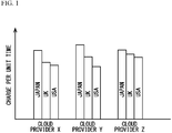
- FIG. 1 is a schematic diagram illustrating the usage charge of the virtual machine per unit time for each cloud provider.
- the usage charge of the virtual machine is different for each of cloud providers X, Y, and Z. Furthermore, even if the cloud provider is the same, the usage charge of the virtual machine varies depending on a region such as Japan, United Kingdom (UK), and United States of America (USA). The region is a place where a data center in which the virtual machines are deployed is installed.
- UK United Kingdom
- USA United States of America
- cloud locations can be expressed as (X, Japan), (Y, UK), (Z, USA) or the like, for example. Furthermore, even if the cloud provider is the same, as indicated by (X, Japan) and (X, UK), the cloud locations may be different from each other.
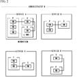
- FIG. 2 is a schematic diagram of services A, B, C and D using virtual machines deployed at different cloud locations P, Q and R.
- P (X, Japan)
- Q (Y, UK)
- R (Z, USA).
- These services A, B, C and D are managed by a same administrator M.
- the administrator M appropriately selects a plurality of virtual machines VM from at least two of the cloud locations P, Q, and R, connects the plurality of virtual machines by a network suitable for the service, and provides it to the user of the service.
- the administrator M selects three virtual machines VM in the cloud location P, and selects one virtual machine VM from each of the cloud locations Q and R. Then, the administrator M connects these virtual machines VM by an appropriate network.
- the cloud provider of the cloud location R reduces the usage charge of a virtual machine VM0.
- the specifications of the virtual machine VM that serves as the reference for migration include the number of virtual CPUs, a capacity of a virtual memory and so on, in the virtual machine VM This allows the administrator M to reduce the usage charge to the user of service A, and the cost of the service A can be reduced.
- FIG. 3 is a schematic diagram illustrating the rate.
- the service A has a maximum ratio of virtual machines having the same specifications as the virtual machine VM0 in the cloud location R to all the virtual machines.
- the service A includes a redundant virtual machine VM
- FIG. 4A is a schematic diagram of a virtual machine having redundant configuration.
- one of the two virtual machines VM having the same function belongs to the cloud location P, and the other belongs to the cloud location R.
- the service A can be provided by the virtual machine VM of the cloud location R, so that the availability of the service A can be improved.
- FIG. 4B is a schematic diagram illustrating a case where the virtual machine in a cloud location P is migrated to the cloud location R.
- the usage charge of the service A can be reduced by migrating the virtual machine VM in this way. Therefore, it is also considered that the administrator M of the service A calculates the charge of the service A after the charge reduction and presents it to the user of the service A.
- both of the two virtual machines VM having the redundant configuration are deployed in the same cloud location R. Therefore, when the failure occurs in the cloud location R, the user cannot use the service A and the availability of service A is reduced.
- Whether the two virtual machines VM have the redundant configuration is determined by application programs that the user of the service A runs on respective virtual machines VM.
- the respective virtual machines VM run the same application programs, for example, the functions of the respective virtual machines VM are the same, and these virtual machines VMs have the redundant configuration.
- the administrator M of the service A knows the network configuration that connects the virtual machines VM to each other, the application programs that run on the respective virtual machines VM are not included in a category managed by the administrator M.
- the user of the service A can voluntarily make the virtual machines VM redundant by running the same application programs on the respective virtual machines VM Therefore, the administrator M of the service A cannot directly determine whether each virtual machine VM has the redundant configuration.
- FIG. 5 is a system configuration diagram of a system according to a present embodiment.
- a system 10 calculates a difference in usage charges for using the service before and after migrating the virtual machine VM to another cloud location, in the service using the virtual machines VM deployed in the cloud locations P, Q, and R.
- the system 10 has an information processing device 12 connected to the cloud locations P, Q, and R via a network 11.
- the combination of any of the cloud providers X, Y, Z and the region is referred to as the cloud location P, Q or R.
- the information processing device 12 is a computer such as a server or a PC (Personal Computer), and accesses charge information 15 of the cloud providers X, Y, and Z via the network 11.
- the charge information 15 is a web page in which charge tables of the virtual machine VM in the respective cloud locations P, Q, and R are described.
- the information processing device 12 can detect whether the usage charge of the virtual machine VM in each of the cloud locations P, Q, and R is reduced, by referring to the charge information 15.
- FIG. 6 is a schematic diagram of services A, B, C and D using virtual machines deployed in cloud locations P, Q and R.
- the administrator N of the system 10 described above manages the cloud locations where the respective virtual machines VM in the services A, B, C, and D are deployed and the network for connecting the respective virtual machines VM
- the administrator N does not manage whether each virtual machine VM has the redundant configuration. Furthermore, each user of the services A, B, C, and D can freely run the application programs on the virtual machines VM, and the administrator N does not have an authority to manage the application programs. Therefore, even if the user runs the same application programs on the two virtual machines VM and makes these virtual machines VM redundant, the administrator N cannot directly know the redundant configuration.
- the information processing device 12 determines a possibility that the virtual machine VM has the redundant configuration as follows.
- the determination method of the redundant configuration includes the following first to fifth examples.
- FIG. 7A is a schematic diagram illustrating a determination method according to the first example.
- a plurality of virtual machines VM that provide service A are referred to as virtual machines VM1, VM2, and VM3.
- the virtual machines VM1, VM2, and VM3 may be deployed in the same cloud location, or may be deployed in different cloud locations.
- the services B, C, and D may be used instead of the service A. This also applies to the second and third examples described later.
- the information processing device 12 monitors traffic volumes tr 1 and tr 2 input to these virtual machines VM1 and VM2, respectively.
- the traffic volumes tr 1 is an example of a first traffic volume
- the traffic volumes tr 2 is an example of a second traffic volume.
- the virtual machine VM3 has a high possibility to function as a load balancer that distributes traffic to the virtual machines VM1 and VM2. Therefore, there should be no large difference between the traffic volumes tr 1 and tr 2 .
- the information processing device 12 monitors the traffic volumes tr 1 and tr 2 to determine a degree of possibility that the virtual machines VM1 and VM2 have the redundant configuration.
- FIG. 7B is a schematic diagram illustrating a monitoring result of the traffic volumes tr 1 and tr 2 in the first example.
- FIG. 8 is a schematic diagram illustrating a determination rule R1 for determining the degree of possibility.
- the information processing device 12 determines the degree of possibility depending on which of the conditions "R1-1", “R1-2", and “R1-3” is satisfied, as illustrated in FIG. 8 .
- the information processing device 12 measures the traffic volumes tr 1 and tr 2 5 times.
- the ratio P t is less than 10% in 4 out of 5 times, the condition "R1-1" is satisfied, and the information processing device 12 determines that there is a high possibility of the redundant configuration.
- the condition "R1-2" is satisfied, and the information processing device 12 determines that there is a medium possibility of the redundant configuration.
- condition "R1-3" is satisfied, and the information processing device 12 determines that there is a low possibility of the redundant configuration.
- FIG. 9A is a schematic diagram illustrating a determination method according to the second example.
- the information processing device 12 monitors an input traffic volume tr 3 input to the virtual machine VM3 and output traffic volumes tr 1 and tr 2 output from the virtual machine VM3 to the virtual machines VM1 and VM2.
- the virtual machine VM3 has the high possibility to function as the load balancer that distributes traffic to the virtual machines VM1 and VM2.
- virtual machine VM3 distributes input data to its own virtual machine to each virtual machine VM1 and VM2 at random in time. Therefore, a total value trtot of the output traffic volumes tr 1 and tr 2 is equal to the input traffic volume tr 3 .
- the information processing device 12 monitors the traffic volumes tr 1 , tr 2 , and tr 3 to determine the degree of possibility that the virtual machines VM1 and VM2 have the redundant configuration.
- FIG. 9B is a schematic diagram illustrating a monitoring result of the traffic volumes tr 1 , tr 2 , and tr 3 .
- the total volumes (bits) of traffic in one minute are set as the traffic volumes tr 1 , tr 2 and tr 3 .
- FIG. 10 is a schematic diagram illustrating a determination rule R2 for determining the degree of possibility.
- the information processing device 12 determines the degree of possibility depending on which of the conditions "R2-1", “R2-2", and “R2-3" is satisfied, as illustrated in FIG. 10 .
- the information processing device 12 measures the traffic volumes tr 1 , tr 2 and tr 3 5 times. When the ratio P b is less than 10% in 4 out of 5 times, the condition "R2-1" is satisfied, and the information processing device 12 determines that there is the high possibility of the redundant configuration.
- the condition "R2-2" is satisfied, and the information processing device 12 determines that there is the medium possibility of the redundant configuration.
- condition "R2-3" is satisfied, and the information processing device 12 determines that there is the low possibility of the redundant configuration.
- FIG. 11A is a schematic diagram illustrating a determination method according to the third example.
- FIG 11A it is assumed a case where the high possibility that the virtual machines VM1 and VM2 in the service A have the redundant configuration, by the first example and the second example, is determined.
- the information processing device 12 monitors a traffic volume tr 4 flowing between the virtual machine VM1 and the virtual machine VM4 and a traffic volume tr 5 flowing between the virtual machine VM2 and the virtual machine VM5. If the virtual machines VM4 and VM5 have the redundant configuration, there should be no large difference between the traffic volumes tr 4 and tr 5 .
- the information processing device 12 monitors the traffic volumes tr 4 and tr 5 to determine the degree of possibility that the virtual machines VM4 and VM5 have the redundant configuration.
- FIG. 11B is a schematic diagram illustrating a monitoring result of the traffic volumes tr 4 and tr 5 .
- FIG. 12 is a schematic diagram illustrating a determination rule R3 for determining the degree of possibility.
- the information processing device 12 determines the degree of possibility depending on which of the conditions "R3-1", “R3-2", and “R3-3" is satisfied, as illustrated in FIG. 12 .
- the information processing device 12 measures the traffic volumes tr 4 and tr 5 5 times.
- the ratio P c is less than 10% in 4 out of 5 times, the condition "R3-1" is satisfied, and the information processing device 12 determines that there is the high possibility of the redundant configuration.
- the condition "R3-2" is satisfied, and the information processing device 12 determines that there is the medium possibility of the redundant configuration.
- condition "R3-3" is satisfied, and the information processing device 12 determines that there is the low possibility of the redundant configuration.
- FIG. 11A is a schematic diagram illustrating a determination method according to the fourth example.
- the information processing device 12 determines a degree of possibility that the virtual machines VM1 and VM2 are redundant databases.
- the virtual machines VM1 and VM2 may be deployed in the same cloud location, or may be deployed in different cloud locations. Further, the services B, C, and D may be used instead of the service A. This also applies to the fifth example described later.
- a content F of a disk D1 in the virtual machine VM1 is copied to a disk D2 in the virtual machine VM2 after a certain period of time ⁇ T elapsed.
- the virtual machine VM2 operates in the same manner as the virtual machine VM1 after the certain period of time ⁇ T. Therefore, a resource usage rate U 2 of the virtual machine VM2 should be the same as a resource usage rate U 1 of the virtual machine VM1 at the time going back by the certain period of time ⁇ T.
- the information processing device 12 monitors the resource usage rates U 1 and U 2 to determine the degree of possibility that the virtual machines VM1 and VM2 have the redundant configuration.
- resource usage rates U 1 and U 2 include a CPU usage rate (%) or a memory usage rate (%) of each of the virtual machines VM1 and VM2.
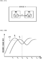
- FIG. 13B is a schematic diagram illustrating a monitoring result of the resource usage rates U 1 an U 2 .
- the graphs of the resource usage rates U1 and U2 have similar shapes as illustrated in FIG. 13B .
- FIG. 14 is a schematic diagram illustrating a determination rule R4 for determining the degree of possibility.
- the information processing device 12 determines the degree of possibility depending on which of the conditions "R4-1", “R4-2", and “R4-3" is satisfied, as illustrated in FIG. 14 .
- the information processing device 12 measures the difference ⁇ U 5 times at different times.
- the information processing device 12 measures the difference ⁇ U between the resource usage rate U 1 at a time t n and the resource usage rate U 2 at a time tn+i.
- the information processing device 12 determines that there is the high possibility that the virtual machines VM1 and VM2 have the redundant configuration.
- the condition "R4-2" is satisfied, and the information processing device 12 determines that there is the medium possibility of the redundant configuration.
- condition "R4-3" is satisfied, and the information processing device 12 determines that there is the low possibility of the redundant configuration.
- FIG. 15A is a schematic diagram illustrating a determination method according to the fifth example.
- FIG 15A it is assumed a case where the high possibility that the virtual machines VM1 and VM2 in the service A have the redundant configuration, by the fourth example, is determined.
- the information processing device 12 monitors the traffic volume tr 4 flowing between the virtual machine VM1 and the virtual machine VM4 and the traffic volume tr 5 flowing between the virtual machine VM2 and the virtual machine VM5. If the virtual machines VM4 and VM5 have the redundant configuration, there should be no large difference between the traffic volumes tr 4 and tr 5 .
- the information processing device 12 monitors the traffic volumes tr 4 and tr 5 to determine the degree of possibility that the virtual machines VM4 and VM5 have the redundant configuration.
- FIG. 15B is a schematic diagram illustrating a monitoring result of the traffic volumes tr 4 and tr 5 .
- FIG. 16 is a schematic diagram illustrating a determination rule R5 for determining the degree of possibility.
- the information processing device 12 determines the degree of possibility depending on which of the conditions "R5-1", “R5-2", and “R5-3" is satisfied, as illustrated in FIG. 16 .
- the information processing device 12 measures the traffic volumes tr 4 and tr 5 5 times.
- the ratio P d is less than 10% in 4 out of 5 times, the condition "R5-1" is satisfied, and the information processing device 12 determines that there is the high possibility of the redundant configuration.
- the condition "R5-2" is satisfied, and the information processing device 12 determines that there is the medium possibility of the redundant configuration.
- condition "R5-3" is satisfied, and the information processing device 12 determines that there is the low possibility of the redundant configuration.
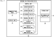
- FIG. 17 is a functional configuration diagram of the information processing device 12. As illustrated in FIG. 17 , the information processing device 12 includes a communication unit 21, a display unit 22, a storage unit 23, and a control unit 24.
- the communication unit 21 is a communication interface for connecting its own device to the network 11 (see FIG. 5 ).
- the display unit 22 is a processing unit that displays a calculation result of a difference between the usage charges before and after the migration of the virtual machine, and is realized by a liquid crystal display device, for example.
- the storage unit 23 is a processing unit realized by, for example, an HDD (Hard Disk Drive), a memory or the like, and stores the above-mentioned determination rules R1 to R5.
- HDD Hard Disk Drive
- the control unit 24 is a processing unit that controls its own device, and includes a detection unit 25, an extraction unit 26, a determination unit 27, a calculation unit 28, a display processing unit 29, a traffic monitoring unit 30 and a resource monitoring unit 31.
- the detection unit 25 is a processing unit that detects that the usage charge of each of the virtual machines VM provided by the cloud providers is reduced by periodically referring to the charge information 15 ( FIG. 5 ) of the cloud providers X, Y, and Z.
- the detection unit 25 stores virtual machine information related to the virtual machine VM whose usage charge is reduced, in the storage unit 23.
- FIG. 18 is a diagram illustrating an example of the virtual machine information.
- the detection unit 25 stores the information related to the virtual machines VM of the cloud locations R and V for which the usage charge is reduced, in the virtual machine information. For example, an item “status” indicating that the usage charge is updated stores “update”. An item “cloud provider” stores the cloud provider “Z” that reduced the usage charge. An item “type” stores “nano” which is a type of the virtual machine VM provided by the cloud provider "Z”. An item “region” stores the regions "USA” and “UK” where the virtual machines VM whose usage charges are reduced are deployed. An item “number of CPU” stores the number of virtual CPUs in the virtual machine whose usage charge is reduced.
- An item "usage charge” stores the usage charge of the virtual machine VM after the charge reduction. Furthermore, an item “OS” stores a name of an OS to be run by the virtual machine VM after the charge reduction.
- the extraction unit 26 extracts a plurality of virtual machines VM having attributes similar to those of the plurality of virtual machines whose usage charges are reduced detected by the detection unit 25, from all the virtual machines VM that provide the service A.
- One of the attributes is the number of virtual CPUs that the virtual machine VM includes. When the number of virtual CPUs in the two virtual machines are the same as each other, it is determined that the attributes of the virtual machines are similar to each other. A capacity of a virtual memory in the virtual machine VM may be adopted as the attribute.
- the extraction unit 26 extracts the virtual machines VM for the services B, C, and D in the same way.
- the determination unit 27 is a processing unit that determines the degree of possibility that the virtual machine VM having the redundant configuration exists in the plurality of virtual machines VM that provide the services. As an example, the determination unit 27 determines the degree of possibility that each of the plurality of virtual machine VMs extracted by the extraction unit 26 has the redundant configuration, according to any of the above-mentioned determination rules R1 to R5. At the time of the determination, the determination unit 27 uses a monitoring result of either the traffic monitoring unit 30 or the resource monitoring unit 31 described later.
- the determination unit 27 identifies the virtual machine VM3 connected to each of the virtual machines VM1 and VM2 as illustrated in FIG. 7A . Then, the determination unit 27 determines the degree of possibility that the virtual machines VM1 and VM2 have the redundant configuration, based on the traffic volumes tr 1 and tr 2 and the determination rule R1 ( FIG. 8 ). This determination is executed by the determination unit 27 for each of the services A, B, C, and D.
- the calculation unit 28 is a processing unit that calculates a difference between the usage charges before and after the migration when a first virtual machine among the plurality of virtual machines is migrated to another cloud location different from the cloud location where the first virtual machine is deployed.
- FIG. 19 is a schematic diagram illustrating an example of deployment destinations of the virtual machines to be calculated.
- the calculation unit 28 calculates the usage charge of the service A when the virtual machine VM1 is migrated to the virtual machine VM6 and the virtual machine VM2 is migrated to the virtual machine VM7, and calculates a difference between calculated usage charge and the usage charge before the migration. This calculation is executed by the calculation unit 28 for each of the services A, B, C, and D.
- the display processing unit 29 is a processing unit that executes a process of displaying the calculation result by the calculation unit 28 and the determination result by the determination unit 27 on the display unit 22.
- the traffic monitoring unit 30 is a processing unit that monitors each of the traffic volumes tr 1 , tr 2 , tr 3 , tr 4 and tr 5 in FIGs. 7A , 9A , 11A and 15A .
- the resource monitoring unit 31 is a processing unit that monitors the resource usage rates U 1 and U 2 in FIG. 13B .
- FIG. 20 is a flowchart of the charge calculation method according to the present embodiment.
- the detection unit 25 detects that the usage charge of the virtual machine provided by any of the cloud providers X, Y, and Z is reduced by referring to the charge information 15 (step S11). Then, the detection unit 25 stores the virtual machine information (see FIG. 18 ) related to the virtual machine whose usage charge is reduced, in the storage unit 23.
- the extraction unit 26 extracts the plurality of virtual machines VM having attributes similar to those of the virtual machines whose usage charges are reduced detected in step S11, from all the virtual machines VM that provide the service A (step S12).
- the extraction unit 26 extracts the plurality of virtual machines VM each having the same number of virtual CPUs as any of the virtual machines VM6 and VM7 from all the virtual machine VMs that provide the service A.
- the capacity of the virtual memory may be used instead of the number of virtual CPUs.
- the extraction unit 26 extracts the plurality of virtual machines VM for the services B, C, and D in the same way.
- the traffic monitoring unit 30 monitors the traffic volumes tr1, tr2, tr3, tr4 and tr5 (see FIGs. 7A , 9A , 11A and 15A ) of the respective extracted virtual machines VM (step S13).
- the resource monitoring unit 31 monitors the resource usage rates U 1 and U 2 (see FIG. 13B ) of the respective extracted virtual machines VM (step S14).
- the determination unit 27 performs a determination process for determining the degree of possibility that the virtual machine having the redundant configuration exist in the plurality of virtual machines providing the service (step S15).
- the determination unit 27 determines the degree of possibility that the respective extracted virtual machines VM have the redundant configuration based on any of the above-mentioned determination rules R1 to R5. The details of the determination process are described later.
- the calculation unit 28 sorts the plurality of services A, B, C, and D (step S16).
- FIG. 21 is a schematic diagram illustrating a sorting method.
- a ratio Z A in FIG. 21 indicates a ratio of the number of virtual machines having attributes similar to those of the virtual machines whose usage charges are reduced, to the number of all virtual machines VM included in the service A. The same applies to the respective ratios Z B , Z C , and Z D of other services B, C, and D.
- the service A Before sorting, the service A has the highest ratio occupied by the virtual machine whose usage charge is reduced.
- each of the ratios Z A , Z B , Z C , and Z D is multiplied by a coefficient ⁇ corresponding to the degree of possibility that the plurality of virtual machines VM having similar attributes to the virtual machine whose usage charge is reduced have the redundant configuration.
- the coefficient ⁇ is a coefficient that decreases as the degree of possibility of the redundant configuration increases.
- the calculation unit 28 multiplies each of the ratios ZA, ZB, ZC, and ZD by the coefficient ⁇ , and sorts the respective services in a descending order of the multiplication results.
- the service B has the largest multiplication result
- the services C, D, and A have smaller multiplication results in that order.
- the sorting method is not limited to this.
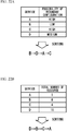
- FIG. 22A is a schematic diagram illustrating another sorting method.
- the services A, B, C, and D are sorted in an ascending order of the degree of possibility of the redundant configuration determined in step S15. For example, it is assumed that the possibility of redundant configuration is high in the services A and C, medium in the service D, and low in the service B, as illustrated in FIG. 22A .
- the calculation unit 28 sorts the services
- the services B, D, A and C are arranged in this order (B -> D-> A -> C).
- FIG. 22B is a schematic diagram illustrating still another sorting method.
- the services A, B, C, and D are sorted in the descending order of the total number of resources included in the respective virtual machines VM extracted in step S12.
- the total number of resources that serve as a basis for sorting is the total number of virtual CPUs in all the extracted virtual machines VM
- a total capacity of the virtual memories in all the extracted virtual machines VM may be adopted as the total number of resources.
- the calculation unit 28 calculates the difference between the usage charges of the service before and after the migration of the virtual machine with reference to the charge information 15 (step S17).
- the calculation unit 28 calculates the difference between the usage charges of the service before and after the migration, based on the charge information 15, when the respective virtual machines VM extracted in step S12 are migrated to the virtual machines VM after the charge reduction.
- the calculation unit 28 calculates the difference between the usage charges in order from the beginning of the services sorted as illustrated in FIG. 21 .
- a calculation order of the difference between the usage charges is an order of the service B, the service C, the service D and the service A.
- step S17 terminates without calculating the difference between the usage charges for subsequent services when a difference between the calculated usage charge and the current usage charge is not equal to or less than a predetermined charge.
- the calculation unit 28 terminates the calculation when it is determined that a migration cost required to migrate the respective virtual machines VM to the virtual machines whose usage charges are reduced is larger than the difference. This avoids a situation where the charge reduction for the respective virtual machines VM is offset by the migration cost, resulting in a higher charge for the service.
- the calculation is performed in order from the service that includes many virtual machines VM having attributes similar to those of the virtual machines whose usage charges are reduced, and has a low possibility that the many virtual machines VM have the redundant configuration. Therefore, the usage charge can be greatly reduced by migrating the virtual machines VM. Further, since the many virtual machines VM do not have the redundant configuration, it is possible to preferentially calculate the service that the user of the service can easily accept the migration.
- the calculation is performed in order from the service provided by the virtual machines having a large total number of resources and a high usage charge. Therefore, the calculation is performed in order from the service with the large charge reduction due to the migration of the virtual machines, and the unnecessary calculation for the service with the small charge reduction that is difficult for the user to accept can be terminated.
- the display processing unit 29 performs a process of displaying the degree of possibility that the virtual machine having the redundant configuration determined in step S15 exists and the calculation result of the difference between the usage charges in step S17 on the display unit 22 (step S18). This completes basic steps in the charge calculation method according to the present embodiment.
- FIG. 23 is a schematic diagram illustrating an example of screen display of the display unit 22 in step S18.
- the display processing unit 29 causes the display unit 22 to display a rate of the charge reduction from the usage charge before the migration in an identifiable manner, as the difference between the usage charges of the service before and after the migration of the virtual machines.
- the display processing unit 29 may display the usage charge after the charge reduction on the display unit 22 instead of the difference between the usage charges.
- the display processing unit 29 causes characters "high”, “medium” and “low” to be displayed on the display unit 22 in the identifiable manner as the degree of the possibility that the virtual machines having the redundant configuration exist in the current respective virtual machines VM
- the administrator N of the services A, B, C, and D can confirm the degree of possibility that the virtual machines VM having the redundant configuration exist in each service, and the difference between the usage charges.
- the administrator N can predict whether the user of the service accepts the migration to another virtual machine whose usage charge is reduced, and then determine whether to present the usage charge after the charge reduction to the user.
- the service A has a maximum charge reduction rate compared to other services, but on the other hand, there is a high possibility that the current virtual machine VM having the attribute similar to that of other virtual machine whose usage charge is reduced has the redundant configuration. If the virtual machine VM is migrated to the other virtual machine whose usage charge is reduced in the same cloud location, the virtual machines VM having the redundant configuration are deployed in the same cloud location. In this case, each virtual machine VM cannot be used when the failure occurs in the above-mentioned cloud location, and hence there is no sense in making each virtual machine VM redundant. Therefore, the administrator N can predict that the user of the service A prevents the migration of the virtual machine, and can refrain from proposing the migration of the virtual machine to the user of service A.
- the service B has a small price reduction rate, but there is a low possibility that the virtual machine VM having the attribute similar to that of the virtual machine whose usage charge is reduced has the redundant configuration. Therefore, even if the virtual machine VM is migrated to the same cloud location where the usage charge is reduced, it is unlikely that the user of the service B is concerned about the redundant configuration of the virtual machine VM to prevent the migration. As a result, the administrator N can positively propose to the user of the service B to migrate the virtual machine.
- step S15 a description is given of the determination process in step S15.
- This determination process can be performed by any one of the following first to fifth examples.
- FIG. 24 is a flowchart of the determination process according to the first example.
- the degree of possibility of the redundant configuration is determined by using the traffic volumes tr 1 and tr 2 illustrated in FIGs. 7A and 7B .
- the determination unit 27 determines whether the ratio P t satisfies the condition "R1-1" of the determination rule R1 (see FIG. 8 ) (step S22). When the ratio P t satisfies the condition "R1-1" (step S22: YES), the process proceeds to step S23, and the determination unit 27 determines that the degree of possibility of the redundant configuration is "high".
- step S24 determines whether the ratio P t satisfies the condition "R1-2" of the determination rule R1 (step S24). When the ratio P t satisfies the condition "R1-2" (step S24: YES), the process proceeds to step S25, and the determination unit 27 determines that the degree of possibility of the redundant configuration is "medium".
- step S24 NO
- the process proceeds to step S26.
- step S26 the determination unit 27 determines that the degree of possibility of the redundant configuration is "low". After this, the process returns to S16 of FIG. 20 .
- FIG. 25 is a flowchart of the determination process according to the second example.
- the degree of possibility of the redundant configuration is determined by using the traffic volumes tr 1 , tr 2 and tr 3 illustrated in FIGs. 9A and 9B .
- step S32 determines whether the ratio P b satisfies the condition "R2-1" of the determination rule R2 (see FIG. 10 ) (step S32).
- step S32: YES determines whether the ratio P b satisfies the condition "R2-1" (step S32: YES).
- step S34 determines whether the ratio P b satisfies the condition "R2-2" of the determination rule R2 (step S34). When the ratio P b satisfies the condition "R2-2" (step S34: YES), the process proceeds to step S35, and the determination unit 27 determines that the degree of possibility of the redundant configuration is "medium".
- step S34 NO
- the process proceeds to step S36.
- step S36 the determination unit 27 determines that the degree of possibility of the redundant configuration is "low". After this, the process returns to S16 of FIG. 20 .
- FIG. 26 is a flowchart of the determination process according to the third example.
- the degree of possibility of the redundant configuration is determined by using the traffic volumes tr 4 and tr 5 illustrated in FIGs. 11A and 11B .
- step S42 determines whether the ratio P c satisfies the condition "R3-1" of the determination rule R3 (see FIG. 12 ) (step S42).
- step S42: YES the process proceeds to step S43, and the determination unit 27 determines that the degree of possibility of the redundant configuration is "high".
- step S44 determines whether the ratio P c satisfies the condition "R3-2" of the determination rule R3 (step S44). When the ratio P c satisfies the condition "R3-2" (step S24: YES), the process proceeds to step S45, and the determination unit 27 determines that the degree of possibility of the redundant configuration is "medium".
- step S44 NO
- the process proceeds to step S46.
- step S46 the determination unit 27 determines that the degree of possibility of the redundant configuration is "low". After this, the process returns to S16 of FIG. 20 .
- FIG. 27 is a flowchart of the determination process according to the fourth example.
- the degree of possibility of the redundant configuration is determined by using the resource usage rates U 1 and U 2 illustrated in FIG. 13B .
- the resource usage rate U 1 is a value at the time t 1
- the resource usage rate U 2 is a value at the time t 2 .
- the determination unit 27 determines whether the ratio P u satisfies the condition "R4-1" of the determination rule R4 (see FIG. 14 ) (step S52). When the ratio P u satisfies the condition "R4-1" (step S52: YES), the process proceeds to step S53, and the determination unit 27 determines that the degree of possibility of the redundant configuration is "high".
- step S52 When the ratio P u does not satisfy the condition "R4-1" (step S52: NO), the process proceeds to step S54.
- the determination unit 27 determines whether the ratio P u satisfies the condition "R4-2" of the determination rule R4 (step S54). When the ratio P u satisfies the condition "R4-2" (step S54: YES), the process proceeds to step S55, and the determination unit 27 determines that the degree of possibility of the redundant configuration is "medium".
- step S54 NO
- the process proceeds to step S56.
- step S56 the determination unit 27 determines that the degree of possibility of the redundant configuration is "low". After this, the process returns to S16 of FIG. 20 .
- FIG. 28 is a flowchart of the determination process according to the fifth example.
- the degree of possibility of the redundant configuration is determined by using the traffic volumes tr 4 and tr 5 illustrated in FIGs. 15A and 15B .
- the determination unit 27 determines whether the ratio P d satisfies the condition "R5-1" of the determination rule R5 (see FIG. 16 ) (step S62). When the ratio P d satisfies the condition "R5-1" (step S62: YES), the process proceeds to step S63, and the determination unit 27 determines that the degree of possibility of the redundant configuration is "high".
- step S62 When the ratio P d does not satisfy the condition "R5-1" (step S62: NO), the process proceeds to step S64.
- the determination unit 27 determines whether the ratio P d satisfies the condition "R5-2" of the determination rule R5 (step S64). When the ratio P d satisfies the condition "R5-2" (step S64: YES), the process proceeds to step S65, and the determination unit 27 determines that the degree of possibility of the redundant configuration is "medium".
- step S64 the determination unit 27 determines that the degree of possibility of the redundant configuration is "low". After this, the process returns to S16 of FIG. 20 .
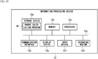
- FIG. 29 is a hardware configuration diagram of the information processing device 12 according to the present embodiment.
- the information processing device 12 includes a storage device 12a, a memory 12b, a processor 12c, a communication interface 12d, a display device 12e, and an input device 12f. These elements are connected to each other by a bus 12g.
- the storage device 12a is a non-volatile storage such as an HDD (Hard Disk Drive) or an SSD (Solid State Drive), and stores a charge calculation program 40 according to the present embodiment.
- HDD Hard Disk Drive
- SSD Solid State Drive
- the charge calculation program 40 may be recorded on a computer-readable recording medium 12h, and the processor 12c may read the charge calculation program 40 from the recording medium 12h.
- Examples of such a recording medium 12h include physically portable recording media such as a CD-ROM (Compact Disc-Read Only Memory), a DVD (Digital Versatile Disc), and a USB (Universal Serial Bus) memory. Further, a semiconductor memory such as a flash memory, or a hard disk drive may be used as the recording medium 12h.
- the recording medium 12h is not a temporary medium such as a carrier wave having no physical form.
- the charge calculation program 40 may be stored in a device connected to a public line, an Internet, a LAN (Local Area Network), or the like.
- the processor 12c may read and execute the charge calculation program 40.
- the memory 12b is hardware that temporarily stores data, such as a DRAM, and the charge calculation program 40 is deployed on the memory 12b.
- the processor 12c is hardware such as a CPU (Central Processing Unit) and a GPU (Graphical Processing Unit) that control each part of the information processing device 12. Further, the processor 12c executes the charge calculation program 40 in cooperation with the memory 12b.
- a CPU Central Processing Unit
- GPU Graphics Processing Unit
- control unit 24 of FIG. 17 is realized by executing the charge calculation program 40 in cooperation with the memory 12b and the processor 12c.
- the control unit 24 includes the detection unit 25, the extraction unit 26, the determination unit 27, the calculation unit 28, the display processing unit 29, the traffic monitoring unit 30, and the resource monitoring unit 31, as described above.
- the storage unit 23 of FIG. 17 is realized by the storage device 12a and the memory 12b.
- the communication interface 12d is a communication interface such as a NIC (Network Interface Card) for connecting the information processing device 12 to the network 11.
- the communication unit 21 of FIG. 17 is realized by the communication interface 12d.
- the display device 12e is hardware such as a liquid crystal display device for realizing the display unit 22 of FIG. 17 .
- the calculation result of FIG. 23 and the possibility of the redundant configuration are displayed on the display device 12e.
- the input device 12f is hardware such as a keyboard and a mouse. For example, the administrator issues various instructions to the information processing device 12 by operating the input device 12f.
Landscapes
- Engineering & Computer Science (AREA)
- Theoretical Computer Science (AREA)
- Business, Economics & Management (AREA)
- Physics & Mathematics (AREA)
- General Physics & Mathematics (AREA)
- General Engineering & Computer Science (AREA)
- Development Economics (AREA)
- Strategic Management (AREA)
- Software Systems (AREA)
- Quality & Reliability (AREA)
- Human Resources & Organizations (AREA)
- Finance (AREA)
- Computing Systems (AREA)
- Accounting & Taxation (AREA)
- Economics (AREA)
- Entrepreneurship & Innovation (AREA)
- General Business, Economics & Management (AREA)
- Game Theory and Decision Science (AREA)
- Marketing (AREA)
- Educational Administration (AREA)
- Mathematical Physics (AREA)
- Computer Networks & Wireless Communication (AREA)
- Signal Processing (AREA)
- Computer Hardware Design (AREA)
- Operations Research (AREA)
- Tourism & Hospitality (AREA)
- Hardware Redundancy (AREA)
- Debugging And Monitoring (AREA)
- Management, Administration, Business Operations System, And Electronic Commerce (AREA)
Abstract
Description
- The present invention relates to a charge calculation program and a charge calculation method.
- With the development of virtualization technology, a cloud that provides various services to a user by using virtual machines running in a data center is widespread. In the cloud, since data and programs required for the service are managed by the virtual machine, it is not necessary for the user to manage the data and the programs, and it is possible to improve the efficiency of user's business and reduce a cost.
- In recent years, a new service that combines clouds from different cloud providers is also proposed. In this service, each of a plurality of virtual machines is realized by the clouds of a plurality of different cloud providers. Thereby, even if a failure occurs in any of the cloud providers, the virtual machines can continue to operate in the cloud of the remaining cloud providers, so that the virtual machines can be made redundant.
- In such a service, some cloud providers may reduce the charge of their own virtual machine. In that case, a usage charge of the service becomes cheaper than a current charge by using the virtual machine after the charge reduction. Therefore, it is preferable to encourage the users of the service to migrate their virtual machine to the virtual machines of the cloud provider that reduce the charge. Note that the technique related to the present disclosure is disclosed in Japanese Patent Application Publication No.
2017-142673 - For example, if respective redundant virtual machines are migrated to the same cloud provider, the respective virtual machines cannot be used in the case where the failure occurs in the cloud provider. Therefore, it makes no sense to make the virtual machines redundant. Moreover, when the user of the service voluntarily makes the virtual machines redundant, it is difficult for an administrator of the service to determine that each of the virtual machines has redundant configuration. When providing candidates for the virtual machines to be migrated to the user of the service, if the above-mentioned virtual machines that are unlikely to be migrated by the user of the service are also included in the candidates, this might prevent the user of the service from selecting the virtual machine to be migrated.
- It is an object of the present disclosure to a charge calculation program and a charge calculation method that can check a degree of possibility that a virtual machine has redundant configuration and a usage charge of a service after charge reduction.
- According to an aspect of the present disclosure, there is provided a charge calculation method executed by a processor included in a computer to execute a process, the process including: determining a degree of possibility that a virtual machine having redundant configuration exists in a plurality of virtual machines that provide a service; calculating a difference of charges for using the service before and after a first virtual machine among the plurality of virtual machines is migrated to an another location different from a location where the first virtual machine is located; and displaying the degree of possibility and the difference with respect to the service.
- According to the present disclosure, it is possible to check a degree of possibility that a virtual machine has redundant configuration and a usage charge of a service after charge reduction.
-
-
FIG. 1 is a schematic diagram illustrating a usage charge of a virtual machine per unit time for each cloud provider; -
FIG. 2 is a schematic diagram of services using virtual machines deployed at different cloud locations; -
FIG. 3 is a schematic diagram illustrating a ratio of virtual machines having the same specifications as virtual machines in a cloud location whose usage charge is reduced, to virtual machines included in each of current services; -
FIG. 4A is a schematic diagram of a virtual machine having redundant configuration; -
FIG. 4B is a schematic diagram illustrating a case where the virtual machine in a cloud location P is migrated to a cloud location R; -
FIG. 5 is a system configuration diagram of a system according to a present embodiment; -
FIG. 6 is a schematic diagram of services using virtual machines deployed in cloud locations in the present embodiment; -
FIG. 7A is a schematic diagram illustrating a determination method according to a first example of the present embodiment; -
FIG. 7B is a schematic diagram illustrating a monitoring result of traffic volumes in the first example; -
FIG. 8 is a schematic diagram illustrating a determination rule according to the first example of the present embodiment; -
FIG. 9A is a schematic diagram illustrating a determination method according to a second example of the present embodiment; -
FIG. 9B is a schematic diagram illustrating a monitoring result of the traffic volumes in the second example; -
FIG. 10 is a schematic diagram illustrating a determination rule according to the second example of the present embodiment; -
FIG. 11A is a schematic diagram illustrating a determination method according to a third example of the present embodiment; -
FIG. 11B is a schematic diagram illustrating a monitoring result of the traffic volumes in the third example; -
FIG. 12 is a schematic diagram illustrating a determination rule according to the third example of the present embodiment; -
FIG. 13A is a schematic diagram illustrating a determination method according to a fourth example of the present embodiment; -
FIG. 13B is a schematic diagram illustrating a monitoring result of resource usage rates in the fourth example; -
FIG. 14 is a schematic diagram illustrating a determination rule according to the fourth example of the present embodiment; -
FIG. 15A is a schematic diagram illustrating a determination method according to a fifth example of the present embodiment; -
FIG. 15B is a schematic diagram illustrating a monitoring result of the traffic volumes in the fifth example; -
FIG. 16 is a schematic diagram illustrating a determination rule according to the fifth example of the present embodiment; -
FIG. 17 is a functional configuration diagram of an information processing device according to the present embodiment; -
FIG. 18 is a diagram illustrating an example of virtual machine information according to the present embodiment; -
FIG. 19 is a schematic diagram illustrating an example of deployment destinations of the virtual machines to be calculated in the present embodiment. -
FIG. 20 is a flowchart of a charge calculation method according to the present embodiment; -
FIG. 21 is a schematic diagram illustrating a sorting method in the present embodiment; -
FIG. 22A is a schematic diagram illustrating another sorting method in the present embodiment; -
FIG. 22B is a schematic diagram illustrating still another sorting method in the present embodiment; -
FIG. 23 is a schematic diagram illustrating an example of screen display of the display unit in the present embodiment; -
FIG. 24 is a flowchart of a determination process according to the first example of the present embodiment; -
FIG. 25 is a flowchart of a determination process according to the second example of the present embodiment; -
FIG. 26 is a flowchart of a determination process according to the third example of the present embodiment; -
FIG. 27 is a flowchart of a determination process according to the fourth example of the present embodiment; -
FIG. 28 is a flowchart of a determination process according to the fifth example of the present embodiment; and -
FIG. 29 is a hardware configuration diagram of the information processing device according to the present embodiment. - Prior to the description of the present embodiment, matters studied by an inventor will be described.
- As described above, in the service that combines the plurality of cloud services, it is preferable to encourage the user to migrate a virtual machine in use to the virtual machine of the cloud provider whose usage charge is reduced, and to propose reduction in a usage charge of the service to the user.
-
FIG. 1 is a schematic diagram illustrating the usage charge of the virtual machine per unit time for each cloud provider. - As illustrated in
FIG. 1 , the usage charge of the virtual machine is different for each of cloud providers X, Y, and Z. Furthermore, even if the cloud provider is the same, the usage charge of the virtual machine varies depending on a region such as Japan, United Kingdom (UK), and United States of America (USA). The region is a place where a data center in which the virtual machines are deployed is installed. - Hereinafter, the combination of each of cloud providers X, Y, Z and the region is referred to as a cloud location. The cloud locations can be expressed as (X, Japan), (Y, UK), (Z, USA) or the like, for example. Furthermore, even if the cloud provider is the same, as indicated by (X, Japan) and (X, UK), the cloud locations may be different from each other.
-
FIG. 2 is a schematic diagram of services A, B, C and D using virtual machines deployed at different cloud locations P, Q and R. As an example, it is assumed that the cloud locations are P = (X, Japan), Q = (Y, UK) and R = (Z, USA). - These services A, B, C and D are managed by a same administrator M. The administrator M appropriately selects a plurality of virtual machines VM from at least two of the cloud locations P, Q, and R, connects the plurality of virtual machines by a network suitable for the service, and provides it to the user of the service.
- When providing a service A to a user, for example, the administrator M selects three virtual machines VM in the cloud location P, and selects one virtual machine VM from each of the cloud locations Q and R. Then, the administrator M connects these virtual machines VM by an appropriate network.
- For example, it is assumed a case where the cloud provider of the cloud location R reduces the usage charge of a virtual machine VM0. In this case, it is preferable to migrate a virtual machine having the same specifications as the virtual machine VM0 among the three virtual machines VM of the cloud location P in the service A to the virtual machine VM0 from a viewpoint of charge reduction. Here, the specifications of the virtual machine VM that serves as the reference for migration include the number of virtual CPUs, a capacity of a virtual memory and so on, in the virtual machine VM This allows the administrator M to reduce the usage charge to the user of service A, and the cost of the service A can be reduced. The same applies to the services B, C, and D.
- How much cost reduction is possible depends on a ratio of virtual machines VM having the same specifications as the virtual machine VM0 of the cloud location R whose usage charge is reduced, to the virtual machines VM included in each of the current services A, B, C, and D.
-
FIG. 3 is a schematic diagram illustrating the rate. In an example ofFIG. 3 , the service A has a maximum ratio of virtual machines having the same specifications as the virtual machine VM0 in the cloud location R to all the virtual machines. - Therefore, significant charge reduction can be realized by migrating a virtual machine having the same specifications as the virtual machine VM0 in the cloud location R among the virtual machines VM of service A, to the cloud location R.
- However, when the service A includes a redundant virtual machine VM, it may be difficult to migrate the virtual machine VM as follows.
-
FIG. 4A is a schematic diagram of a virtual machine having redundant configuration. In an example ofFIG. 4A , one of the two virtual machines VM having the same function belongs to the cloud location P, and the other belongs to the cloud location R. Thereby, even if the failure occurs in the cloud location P, for example, the service A can be provided by the virtual machine VM of the cloud location R, so that the availability of the service A can be improved. -
FIG. 4B is a schematic diagram illustrating a case where the virtual machine in a cloud location P is migrated to the cloud location R. - When the charge of the virtual machine VM in the cloud location R is reduced, the usage charge of the service A can be reduced by migrating the virtual machine VM in this way. Therefore, it is also considered that the administrator M of the service A calculates the charge of the service A after the charge reduction and presents it to the user of the service A.
- However, in this case, both of the two virtual machines VM having the redundant configuration are deployed in the same cloud location R. Therefore, when the failure occurs in the cloud location R, the user cannot use the service A and the availability of service A is reduced.
- Whether the two virtual machines VM have the redundant configuration is determined by application programs that the user of the service A runs on respective virtual machines VM. When the respective virtual machines VM run the same application programs, for example, the functions of the respective virtual machines VM are the same, and these virtual machines VMs have the redundant configuration.
- However, although the administrator M of the service A knows the network configuration that connects the virtual machines VM to each other, the application programs that run on the respective virtual machines VM are not included in a category managed by the administrator M. The user of the service A can voluntarily make the virtual machines VM redundant by running the same application programs on the respective virtual machines VM Therefore, the administrator M of the service A cannot directly determine whether each virtual machine VM has the redundant configuration.
- Therefore, even if the user of the service A is encouraged to migrate the virtual machine VM to the cloud location R, it is unlikely that the user of the service A accepts it, and the calculation of a new usage charge becomes useless.
- Hereinafter, each embodiment capable of eliminating such uselessness is described.
-
FIG. 5 is a system configuration diagram of a system according to a present embodiment. Asystem 10 calculates a difference in usage charges for using the service before and after migrating the virtual machine VM to another cloud location, in the service using the virtual machines VM deployed in the cloud locations P, Q, and R. In this example, thesystem 10 has aninformation processing device 12 connected to the cloud locations P, Q, and R via anetwork 11. As described above, also in the present embodiment, the combination of any of the cloud providers X, Y, Z and the region is referred to as the cloud location P, Q or R. The cloud locations are P = (X, Japan), Q = (Y, UK) and R = (Z, USA), for example. - The
information processing device 12 is a computer such as a server or a PC (Personal Computer), and accessescharge information 15 of the cloud providers X, Y, and Z via thenetwork 11. Thecharge information 15 is a web page in which charge tables of the virtual machine VM in the respective cloud locations P, Q, and R are described. Theinformation processing device 12 can detect whether the usage charge of the virtual machine VM in each of the cloud locations P, Q, and R is reduced, by referring to thecharge information 15. -
FIG. 6 is a schematic diagram of services A, B, C and D using virtual machines deployed in cloud locations P, Q and R. - The administrator N of the
system 10 described above manages the cloud locations where the respective virtual machines VM in the services A, B, C, and D are deployed and the network for connecting the respective virtual machines VM - However, the administrator N does not manage whether each virtual machine VM has the redundant configuration. Furthermore, each user of the services A, B, C, and D can freely run the application programs on the virtual machines VM, and the administrator N does not have an authority to manage the application programs. Therefore, even if the user runs the same application programs on the two virtual machines VM and makes these virtual machines VM redundant, the administrator N cannot directly know the redundant configuration.
- Therefore, in the present embodiment, the
information processing device 12 determines a possibility that the virtual machine VM has the redundant configuration as follows. The determination method of the redundant configuration includes the following first to fifth examples. -
FIG. 7A is a schematic diagram illustrating a determination method according to the first example. Hereinafter, a plurality of virtual machines VM that provide service A are referred to as virtual machines VM1, VM2, and VM3. The virtual machines VM1, VM2, and VM3 may be deployed in the same cloud location, or may be deployed in different cloud locations. Further, the services B, C, and D may be used instead of the service A. This also applies to the second and third examples described later. - In this example, when there are two virtual machines VM1 and VM2 under the control of a single virtual machine VM3, the
information processing device 12 monitors traffic volumes tr1 and tr2 input to these virtual machines VM1 and VM2, respectively. Note that the traffic volumes tr1 is an example of a first traffic volume, and the traffic volumes tr2 is an example of a second traffic volume. - If the virtual machines VM1 and VM2 have the redundant configuration, the virtual machine VM3 has a high possibility to function as a load balancer that distributes traffic to the virtual machines VM1 and VM2. Therefore, there should be no large difference between the traffic volumes tr1 and tr2.
- Therefore, in this example, the
information processing device 12 monitors the traffic volumes tr1 and tr2 to determine a degree of possibility that the virtual machines VM1 and VM2 have the redundant configuration. -
FIG. 7B is a schematic diagram illustrating a monitoring result of the traffic volumes tr1 and tr2 in the first example. - In this example, total volumes (bits) of traffic in one minute are set as the traffic volumes tr1 and tr2, and the
information processing device 12 calculates a difference Δtra between them. Then, theinformation processing device 12 determines the degree of possibility of the redundant configuration based on a ratio Pt (= Δtra/tr1) occupied by the difference Δtra to the traffic amount tr1. -
FIG. 8 is a schematic diagram illustrating a determination rule R1 for determining the degree of possibility. - In the determination rule R1, the
information processing device 12 determines the degree of possibility depending on which of the conditions "R1-1", "R1-2", and "R1-3" is satisfied, as illustrated inFIG. 8 . - Here, the
information processing device 12 measures the traffic volumes tr1 andtr 2 5 times. When the ratio Pt is less than 10% in 4 out of 5 times, the condition "R1-1" is satisfied, and theinformation processing device 12 determines that there is a high possibility of the redundant configuration. - When the ratio Pt is less than 30% in 4 out of 5 times, or the ratio Pt is less than 10% in 2 out of 5 times, the condition "R1-2" is satisfied, and the
information processing device 12 determines that there is a medium possibility of the redundant configuration. - In any other cases, the condition "R1-3" is satisfied, and the
information processing device 12 determines that there is a low possibility of the redundant configuration. -
FIG. 9A is a schematic diagram illustrating a determination method according to the second example. In this example, it is assumed a case where there are the two virtual machines VM1 and VM2 under the control of the single virtual machine VM3 in the service A. In this case, theinformation processing device 12 monitors an input traffic volume tr3 input to the virtual machine VM3 and output traffic volumes tr1 and tr2 output from the virtual machine VM3 to the virtual machines VM1 and VM2. - If the virtual machines VM1 and VM2 have the redundant configuration, the virtual machine VM3 has the high possibility to function as the load balancer that distributes traffic to the virtual machines VM1 and VM2. In this case, virtual machine VM3 distributes input data to its own virtual machine to each virtual machine VM1 and VM2 at random in time. Therefore, a total value trtot of the output traffic volumes tr1 and tr2 is equal to the input traffic volume tr3.
- Therefore, in this example, the
information processing device 12 monitors the traffic volumes tr1, tr2, and tr3 to determine the degree of possibility that the virtual machines VM1 and VM2 have the redundant configuration. -
FIG. 9B is a schematic diagram illustrating a monitoring result of the traffic volumes tr1, tr2, and tr3. - In this example, the total volumes (bits) of traffic in one minute are set as the traffic volumes tr1, tr2 and tr3. The
information processing device 12 calculates a difference Δtrb between the total value trtot of the output traffic volumes tr1 and tr2 and the input traffic volume tr3. Further, theinformation processing device 12 determines the degree of possibility of the redundant configuration based on a ratio Pb (= Δtrb/tr3) occupied by the difference Δtrb to the input traffic volume tr3. -
FIG. 10 is a schematic diagram illustrating a determination rule R2 for determining the degree of possibility. - In the determination rule R2, the
information processing device 12 determines the degree of possibility depending on which of the conditions "R2-1", "R2-2", and "R2-3" is satisfied, as illustrated inFIG. 10 . - Here, the
information processing device 12 measures the traffic volumes tr1, tr2 andtr 3 5 times. When the ratio Pb is less than 10% in 4 out of 5 times, the condition "R2-1" is satisfied, and theinformation processing device 12 determines that there is the high possibility of the redundant configuration. - When the ratio Pb is less than 30% in 4 out of 5 times, or the ratio Pb is less than 10% in 2 out of 5 times, the condition "R2-2" is satisfied, and the
information processing device 12 determines that there is the medium possibility of the redundant configuration. - In any other cases, the condition "R2-3" is satisfied, and the
information processing device 12 determines that there is the low possibility of the redundant configuration. -
FIG. 11A is a schematic diagram illustrating a determination method according to the third example. InFIG 11A , it is assumed a case where the high possibility that the virtual machines VM1 and VM2 in the service A have the redundant configuration, by the first example and the second example, is determined. In this case, there is a high possibility that virtual machines VM4 and VM5 in the service A under the control of the virtual machines VM1 and VM2 also have the redundant configuration. - In order to confirm this, the
information processing device 12 monitors a traffic volume tr4 flowing between the virtual machine VM1 and the virtual machine VM4 and a traffic volume tr5 flowing between the virtual machine VM2 and the virtual machine VM5. If the virtual machines VM4 and VM5 have the redundant configuration, there should be no large difference between the traffic volumes tr4 and tr5. - Therefore, in this example, the
information processing device 12 monitors the traffic volumes tr4 and tr5 to determine the degree of possibility that the virtual machines VM4 and VM5 have the redundant configuration. -
FIG. 11B is a schematic diagram illustrating a monitoring result of the traffic volumes tr4 and tr5. - In this example, the total volumes (bits) of traffic in one minute are set as the traffic volumes tr4 and tr5, and the
information processing device 12 calculates a difference Δtrc between them. Then, theinformation processing device 12 determines the degree of possibility of the redundant configuration based on a ratio Pc (= Δtrc/tr4) occupied by the difference Δtrc to the traffic volume tr4. -
FIG. 12 is a schematic diagram illustrating a determination rule R3 for determining the degree of possibility. - In the determination rule R3, the
information processing device 12 determines the degree of possibility depending on which of the conditions "R3-1", "R3-2", and "R3-3" is satisfied, as illustrated inFIG. 12 . - Here, the
information processing device 12 measures the traffic volumes tr4 andtr 5 5 times. When the ratio Pc is less than 10% in 4 out of 5 times, the condition "R3-1" is satisfied, and theinformation processing device 12 determines that there is the high possibility of the redundant configuration. - When the ratio Pc is less than 30% in 4 out of 5 times, or the ratio Pc is less than 10% in 2 out of 5 times, the condition "R3-2" is satisfied, and the
information processing device 12 determines that there is the medium possibility of the redundant configuration. - In any other cases, the condition "R3-3" is satisfied, and the
information processing device 12 determines that there is the low possibility of the redundant configuration. -
FIG. 11A is a schematic diagram illustrating a determination method according to the fourth example. In this example, when the two virtual machines VM1 and VM2 that provide the service A are connected by a network, theinformation processing device 12 determines a degree of possibility that the virtual machines VM1 and VM2 are redundant databases. The virtual machines VM1 and VM2 may be deployed in the same cloud location, or may be deployed in different cloud locations. Further, the services B, C, and D may be used instead of the service A. This also applies to the fifth example described later. - When the virtual machines VM1 and VM2 are the redundant databases, a content F of a disk D1 in the virtual machine VM1 is copied to a disk D2 in the virtual machine VM2 after a certain period of time ΔT elapsed. In this case, the virtual machine VM2 operates in the same manner as the virtual machine VM1 after the certain period of time ΔT. Therefore, a resource usage rate U2 of the virtual machine VM2 should be the same as a resource usage rate U1 of the virtual machine VM1 at the time going back by the certain period of time ΔT.
- Therefore, in this example, the
information processing device 12 monitors the resource usage rates U1 and U2 to determine the degree of possibility that the virtual machines VM1 and VM2 have the redundant configuration. Examples of such resource usage rates U1 and U2 include a CPU usage rate (%) or a memory usage rate (%) of each of the virtual machines VM1 and VM2. -
FIG. 13B is a schematic diagram illustrating a monitoring result of the resource usage rates U1 an U2. - When the virtual machines VM1 and VM2 have the redundant configuration, the graphs of the resource usage rates U1 and U2 have similar shapes as illustrated in
FIG. 13B . - In this example, the
information processing device 12 calculates a difference ΔU between a value of the resource usage rate U1 at a time t1 and a value of the resource usage rate U2 at a time t2. Then, theinformation processing device 12 determines the degree of possibility of the redundant configuration based on a ratio Pu (= ΔU/U1) occupied by the difference ΔU to the resource usage rate U1. -
FIG. 14 is a schematic diagram illustrating a determination rule R4 for determining the degree of possibility. - In the determination rule R4, the
information processing device 12 determines the degree of possibility depending on which of the conditions "R4-1", "R4-2", and "R4-3" is satisfied, as illustrated inFIG. 14 . - In this example, the
information processing device 12 measures thedifference ΔU 5 times at different times. In this case, in the n-th measurement, theinformation processing device 12 measures the difference ΔU between the resource usage rate U1 at a time tn and the resource usage rate U2 at a time tn+i. A value of "tn - tn+i" is the same for all n, and "tn - tn+1" is expressed as ΔT (tn - tn+1 = ΔT). - When the ratio Pu is less than 10% in 4 or more out of 5 times, the condition "R4-1" is satisfied, and the
information processing device 12 determines that there is the high possibility that the virtual machines VM1 and VM2 have the redundant configuration. - When the ratio Pu is less than 30% in 4 or more out of 5 times, or the ratio Pu is less than 10% in 2 or more out of 5 times, the condition "R4-2" is satisfied, and the
information processing device 12 determines that there is the medium possibility of the redundant configuration. - In any other cases, the condition "R4-3" is satisfied, and the
information processing device 12 determines that there is the low possibility of the redundant configuration. -
FIG. 15A is a schematic diagram illustrating a determination method according to the fifth example. InFIG 15A , it is assumed a case where the high possibility that the virtual machines VM1 and VM2 in the service A have the redundant configuration, by the fourth example, is determined. In this case, there is a high possibility that virtual machines VM4 and VM5 in the service A which are connected to the virtual machines VM1 and VM2, respectively, also have the redundant. - In order to confirm this, the
information processing device 12 monitors the traffic volume tr4 flowing between the virtual machine VM1 and the virtual machine VM4 and the traffic volume tr5 flowing between the virtual machine VM2 and the virtual machine VM5. If the virtual machines VM4 and VM5 have the redundant configuration, there should be no large difference between the traffic volumes tr4 and tr5. - Therefore, in this example, the
information processing device 12 monitors the traffic volumes tr4 and tr5 to determine the degree of possibility that the virtual machines VM4 and VM5 have the redundant configuration. -
FIG. 15B is a schematic diagram illustrating a monitoring result of the traffic volumes tr4 and tr5. - In this example, the total volumes (bits) of traffic in one minute are set as the traffic volumes tr4 and tr5, and the
information processing device 12 calculates a difference Δtrd between them. Then, theinformation processing device 12 determines the degree of possibility of the redundant configuration based on a ratio Pd (= Δtrd/tr4) occupied by the difference Δtrd to the traffic volume tr4. -
FIG. 16 is a schematic diagram illustrating a determination rule R5 for determining the degree of possibility. - In the determination rule R5, the
information processing device 12 determines the degree of possibility depending on which of the conditions "R5-1", "R5-2", and "R5-3" is satisfied, as illustrated inFIG. 16 . - Here, the
information processing device 12 measures the traffic volumes tr4 andtr 5 5 times. When the ratio Pd is less than 10% in 4 out of 5 times, the condition "R5-1" is satisfied, and theinformation processing device 12 determines that there is the high possibility of the redundant configuration. - When the ratio Pd is less than 30% in 4 out of 5 times, or the ratio Pd is less than 10% in 2 out of 5 times, the condition "R5-2" is satisfied, and the
information processing device 12 determines that there is the medium possibility of the redundant configuration. - In any other cases, the condition "R5-3" is satisfied, and the
information processing device 12 determines that there is the low possibility of the redundant configuration. - Next, a description is given of the functional configuration of the
information processing device 12.FIG. 17 is a functional configuration diagram of theinformation processing device 12. As illustrated inFIG. 17 , theinformation processing device 12 includes acommunication unit 21, adisplay unit 22, astorage unit 23, and acontrol unit 24. - The
communication unit 21 is a communication interface for connecting its own device to the network 11 (seeFIG. 5 ). Thedisplay unit 22 is a processing unit that displays a calculation result of a difference between the usage charges before and after the migration of the virtual machine, and is realized by a liquid crystal display device, for example. - The
storage unit 23 is a processing unit realized by, for example, an HDD (Hard Disk Drive), a memory or the like, and stores the above-mentioned determination rules R1 to R5. - The
control unit 24 is a processing unit that controls its own device, and includes adetection unit 25, anextraction unit 26, adetermination unit 27, acalculation unit 28, adisplay processing unit 29, atraffic monitoring unit 30 and aresource monitoring unit 31. - The
detection unit 25 is a processing unit that detects that the usage charge of each of the virtual machines VM provided by the cloud providers is reduced by periodically referring to the charge information 15 (FIG. 5 ) of the cloud providers X, Y, and Z. - Further, the
detection unit 25 stores virtual machine information related to the virtual machine VM whose usage charge is reduced, in thestorage unit 23. -
FIG. 18 is a diagram illustrating an example of the virtual machine information.FIG. 18 illustrates a case where the usage charge of each of the virtual machines VM is reduced in the two cloud locations R (= (Z, USA)) and V (= (Z, UK)). - In this case, the
detection unit 25 stores the information related to the virtual machines VM of the cloud locations R and V for which the usage charge is reduced, in the virtual machine information. For example, an item "status" indicating that the usage charge is updated stores "update". An item "cloud provider" stores the cloud provider "Z" that reduced the usage charge. An item "type" stores "nano" which is a type of the virtual machine VM provided by the cloud provider "Z". An item "region" stores the regions "USA" and "UK" where the virtual machines VM whose usage charges are reduced are deployed. An item "number of CPU" stores the number of virtual CPUs in the virtual machine whose usage charge is reduced. - An item "usage charge" stores the usage charge of the virtual machine VM after the charge reduction. Furthermore, an item "OS" stores a name of an OS to be run by the virtual machine VM after the charge reduction.
- Referring to
FIG. 17 again, theextraction unit 26 extracts a plurality of virtual machines VM having attributes similar to those of the plurality of virtual machines whose usage charges are reduced detected by thedetection unit 25, from all the virtual machines VM that provide the service A. One of the attributes is the number of virtual CPUs that the virtual machine VM includes. When the number of virtual CPUs in the two virtual machines are the same as each other, it is determined that the attributes of the virtual machines are similar to each other. A capacity of a virtual memory in the virtual machine VM may be adopted as the attribute. In addition, theextraction unit 26 extracts the virtual machines VM for the services B, C, and D in the same way. - The
determination unit 27 is a processing unit that determines the degree of possibility that the virtual machine VM having the redundant configuration exists in the plurality of virtual machines VM that provide the services. As an example, thedetermination unit 27 determines the degree of possibility that each of the plurality of virtual machine VMs extracted by theextraction unit 26 has the redundant configuration, according to any of the above-mentioned determination rules R1 to R5. At the time of the determination, thedetermination unit 27 uses a monitoring result of either thetraffic monitoring unit 30 or theresource monitoring unit 31 described later. - For example, it is assumed that the virtual machines extracted by the
extraction unit 26 are the virtual machines VM1 and VM2 in the service A. In this case, thedetermination unit 27 identifies the virtual machine VM3 connected to each of the virtual machines VM1 and VM2 as illustrated inFIG. 7A . Then, thedetermination unit 27 determines the degree of possibility that the virtual machines VM1 and VM2 have the redundant configuration, based on the traffic volumes tr1 and tr2 and the determination rule R1 (FIG. 8 ). This determination is executed by thedetermination unit 27 for each of the services A, B, C, and D. - The
calculation unit 28 is a processing unit that calculates a difference between the usage charges before and after the migration when a first virtual machine among the plurality of virtual machines is migrated to another cloud location different from the cloud location where the first virtual machine is deployed. -
FIG. 19 is a schematic diagram illustrating an example of deployment destinations of the virtual machines to be calculated. - Hereinafter, a description is given of a case of calculating the usage charges before and after the migration of the virtual machine VM for providing the service A as an example. In this case, it is assumed that the virtual machines extracted by the
extraction unit 26 are the virtual machine VM1 in the cloud location P and the virtual machine VM2 in the cloud location Q. Further, it is assumed that the virtual machines whose usage charges are reduced are virtual machines VM6 and VM7 in the cloud location R. In this case, thecalculation unit 28 calculates the usage charge of the service A when the virtual machine VM1 is migrated to the virtual machine VM6 and the virtual machine VM2 is migrated to the virtual machine VM7, and calculates a difference between calculated usage charge and the usage charge before the migration. This calculation is executed by thecalculation unit 28 for each of the services A, B, C, and D. - Referring to
FIG. 17 again, thedisplay processing unit 29 is a processing unit that executes a process of displaying the calculation result by thecalculation unit 28 and the determination result by thedetermination unit 27 on thedisplay unit 22. - The
traffic monitoring unit 30 is a processing unit that monitors each of the traffic volumes tr1, tr2, tr3, tr4 and tr5 inFIGs. 7A ,9A ,11A and15A . Theresource monitoring unit 31 is a processing unit that monitors the resource usage rates U1 and U2 inFIG. 13B . - Next, a description is given of a charge calculation method according to the present embodiment.
FIG. 20 is a flowchart of the charge calculation method according to the present embodiment. First, thedetection unit 25 detects that the usage charge of the virtual machine provided by any of the cloud providers X, Y, and Z is reduced by referring to the charge information 15 (step S11). Then, thedetection unit 25 stores the virtual machine information (seeFIG. 18 ) related to the virtual machine whose usage charge is reduced, in thestorage unit 23. - Next, the
extraction unit 26 extracts the plurality of virtual machines VM having attributes similar to those of the virtual machines whose usage charges are reduced detected in step S11, from all the virtual machines VM that provide the service A (step S12). - For example, it is assumed that the virtual machines in which the reduction of the usage charge detected are the virtual machines VM6 and VM7 in the cloud location R (see
FIG. 19 ). In this case, theextraction unit 26 extracts the plurality of virtual machines VM each having the same number of virtual CPUs as any of the virtual machines VM6 and VM7 from all the virtual machine VMs that provide the service A. The capacity of the virtual memory may be used instead of the number of virtual CPUs. Further, theextraction unit 26 extracts the plurality of virtual machines VM for the services B, C, and D in the same way. - Next, the
traffic monitoring unit 30 monitors the traffic volumes tr1, tr2, tr3, tr4 and tr5 (seeFIGs. 7A ,9A ,11A and15A ) of the respective extracted virtual machines VM (step S13). - Further, the
resource monitoring unit 31 monitors the resource usage rates U1 and U2 (seeFIG. 13B ) of the respective extracted virtual machines VM (step S14). - Next, the
determination unit 27 performs a determination process for determining the degree of possibility that the virtual machine having the redundant configuration exist in the plurality of virtual machines providing the service (step S15). Here, thedetermination unit 27 determines the degree of possibility that the respective extracted virtual machines VM have the redundant configuration based on any of the above-mentioned determination rules R1 to R5. The details of the determination process are described later. - Next, the
calculation unit 28 sorts the plurality of services A, B, C, and D (step S16). -
FIG. 21 is a schematic diagram illustrating a sorting method. A ratio ZA inFIG. 21 indicates a ratio of the number of virtual machines having attributes similar to those of the virtual machines whose usage charges are reduced, to the number of all virtual machines VM included in the service A. The same applies to the respective ratios ZB, ZC, and ZD of other services B, C, and D. - Before sorting, the service A has the highest ratio occupied by the virtual machine whose usage charge is reduced.
- In this embodiment, each of the ratios ZA, ZB, ZC, and ZD is multiplied by a coefficient α corresponding to the degree of possibility that the plurality of virtual machines VM having similar attributes to the virtual machine whose usage charge is reduced have the redundant configuration. The coefficient α is a coefficient that decreases as the degree of possibility of the redundant configuration increases. Here, the coefficient α is set to 0.1 (α = 0.1) when the possibility of the redundant configuration is high, and the coefficient α is set to 0.5 (α = 0.5) when the possibility of the redundant configuration is medium. Moreover, the coefficient α is set to 1 (α = 1) when the possibility of the redundant configuration is low.
- Here, it is assumed that the service A has a high possibility of including the virtual machine VM having the redundant configuration and the coefficient α is set to 0.1 (α = 0.1). It is assumed that each of the services C and D has a medium possibility of including the virtual machine VM having the redundant configuration and the coefficient α is set to 0.5 (α = 0.5). Further, it is assumed that each of the services C and D has a low possibility of including the virtual machine VM having the redundant configuration and the coefficient α is set to 1 (α = 1).
- The
calculation unit 28 multiplies each of the ratios ZA, ZB, ZC, and ZD by the coefficient α, and sorts the respective services in a descending order of the multiplication results. In this example, the service B has the largest multiplication result, and the services C, D, and A have smaller multiplication results in that order. The sorting method is not limited to this.FIG. 22A is a schematic diagram illustrating another sorting method. - In this example, the services A, B, C, and D are sorted in an ascending order of the degree of possibility of the redundant configuration determined in step S15. For example, it is assumed that the possibility of redundant configuration is high in the services A and C, medium in the service D, and low in the service B, as illustrated in
FIG. 22A . - In this case, when the
calculation unit 28 sorts the services, the services B, D, A and C are arranged in this order (B -> D-> A -> C). -
FIG. 22B is a schematic diagram illustrating still another sorting method. In this example, the services A, B, C, and D are sorted in the descending order of the total number of resources included in the respective virtual machines VM extracted in step S12. The total number of resources that serve as a basis for sorting is the total number of virtual CPUs in all the extracted virtual machines VM Further, a total capacity of the virtual memories in all the extracted virtual machines VM may be adopted as the total number of resources. - In case of
FIG. 22B , when thecalculation unit 28 sorts the services, the services D, B, C and A are arranged in this order (D -> B -> C -> A). - Referring to
FIG. 20 again, thecalculation unit 28 calculates the difference between the usage charges of the service before and after the migration of the virtual machine with reference to the charge information 15 (step S17). Here, thecalculation unit 28 calculates the difference between the usage charges of the service before and after the migration, based on thecharge information 15, when the respective virtual machines VM extracted in step S12 are migrated to the virtual machines VM after the charge reduction. - At this time, the
calculation unit 28 calculates the difference between the usage charges in order from the beginning of the services sorted as illustrated inFIG. 21 . In the example ofFIG. 21 , a calculation order of the difference between the usage charges is an order of the service B, the service C, the service D and the service A. - The calculation process of step S17 terminates without calculating the difference between the usage charges for subsequent services when a difference between the calculated usage charge and the current usage charge is not equal to or less than a predetermined charge. For example, the
calculation unit 28 terminates the calculation when it is determined that a migration cost required to migrate the respective virtual machines VM to the virtual machines whose usage charges are reduced is larger than the difference. This avoids a situation where the charge reduction for the respective virtual machines VM is offset by the migration cost, resulting in a higher charge for the service. - In the present embodiment, as a result of the sorting as illustrated in
FIG. 21 , the calculation is performed in order from the service that includes many virtual machines VM having attributes similar to those of the virtual machines whose usage charges are reduced, and has a low possibility that the many virtual machines VM have the redundant configuration. Therefore, the usage charge can be greatly reduced by migrating the virtual machines VM. Further, since the many virtual machines VM do not have the redundant configuration, it is possible to preferentially calculate the service that the user of the service can easily accept the migration. - On the other hand, with respect to the service where there are few virtual machines VM having attributes similar to those of the virtual machines whose usage charges are reduced and the charge reduction cannot be expected so much, the calculation is likely to be terminated, and unnecessary calculation can be avoided. Similarly, with respect to the service where there is a high possibility that the respective virtual machines VM have the redundant configuration and it is expected that the user of the service hardly accepts the migration of the virtual machines VM, the calculation is terminated and the unnecessary calculation can be avoided.
- Similarly, also when the sorting is performed based on the degree of possibility of the redundant configuration as illustrated in
FIG. 22A , the calculation for the service having a high possibility of the redundant configuration is likely to be terminated, and the unnecessary calculation can be avoided. - When the sorting is performed based on the total number of resources as illustrated in
FIG. 22B , the calculation is performed in order from the service provided by the virtual machines having a large total number of resources and a high usage charge. Therefore, the calculation is performed in order from the service with the large charge reduction due to the migration of the virtual machines, and the unnecessary calculation for the service with the small charge reduction that is difficult for the user to accept can be terminated. - Then, the
display processing unit 29 performs a process of displaying the degree of possibility that the virtual machine having the redundant configuration determined in step S15 exists and the calculation result of the difference between the usage charges in step S17 on the display unit 22 (step S18). This completes basic steps in the charge calculation method according to the present embodiment. -
FIG. 23 is a schematic diagram illustrating an example of screen display of thedisplay unit 22 in step S18. - In this example, the
display processing unit 29 causes thedisplay unit 22 to display a rate of the charge reduction from the usage charge before the migration in an identifiable manner, as the difference between the usage charges of the service before and after the migration of the virtual machines. Thedisplay processing unit 29 may display the usage charge after the charge reduction on thedisplay unit 22 instead of the difference between the usage charges. - The
display processing unit 29 causes characters "high", "medium" and "low" to be displayed on thedisplay unit 22 in the identifiable manner as the degree of the possibility that the virtual machines having the redundant configuration exist in the current respective virtual machines VM - Thereby, the administrator N of the services A, B, C, and D can confirm the degree of possibility that the virtual machines VM having the redundant configuration exist in each service, and the difference between the usage charges. As a result, the administrator N can predict whether the user of the service accepts the migration to another virtual machine whose usage charge is reduced, and then determine whether to present the usage charge after the charge reduction to the user.
- For example, the service A has a maximum charge reduction rate compared to other services, but on the other hand, there is a high possibility that the current virtual machine VM having the attribute similar to that of other virtual machine whose usage charge is reduced has the redundant configuration. If the virtual machine VM is migrated to the other virtual machine whose usage charge is reduced in the same cloud location, the virtual machines VM having the redundant configuration are deployed in the same cloud location. In this case, each virtual machine VM cannot be used when the failure occurs in the above-mentioned cloud location, and hence there is no sense in making each virtual machine VM redundant. Therefore, the administrator N can predict that the user of the service A prevents the migration of the virtual machine, and can refrain from proposing the migration of the virtual machine to the user of service A.
- Moreover, since it is possible to prevent the administrator N from accidentally migrating the virtual machine VM having the redundant configuration to the same cloud location, it is also possible to obtain a technical improvement that the availability of service A can be prevented from decreasing.
- On the contrary, the service B has a small price reduction rate, but there is a low possibility that the virtual machine VM having the attribute similar to that of the virtual machine whose usage charge is reduced has the redundant configuration. Therefore, even if the virtual machine VM is migrated to the same cloud location where the usage charge is reduced, it is unlikely that the user of the service B is concerned about the redundant configuration of the virtual machine VM to prevent the migration. As a result, the administrator N can positively propose to the user of the service B to migrate the virtual machine.
- Next, a description is given of the determination process in step S15. This determination process can be performed by any one of the following first to fifth examples.
-
FIG. 24 is a flowchart of the determination process according to the first example. In this example, the degree of possibility of the redundant configuration is determined by using the traffic volumes tr1 and tr2 illustrated inFIGs. 7A and 7B . - First, the
determination unit 27 calculates the difference Δtra between the traffic volumes tr1 and tr2 monitored by the traffic monitoring unit 30 (step S21), and further calculates the ratio Pt (= Δtra/tr1). - Next, the
determination unit 27 determines whether the ratio Pt satisfies the condition "R1-1" of the determination rule R1 (seeFIG. 8 ) (step S22). When the ratio Pt satisfies the condition "R1-1" (step S22: YES), the process proceeds to step S23, and thedetermination unit 27 determines that the degree of possibility of the redundant configuration is "high". - When the ratio Pt does not satisfy the condition "R1-1" (step S22: NO), the process proceeds to step S24. The
determination unit 27 determines whether the ratio Pt satisfies the condition "R1-2" of the determination rule R1 (step S24). When the ratio Pt satisfies the condition "R1-2" (step S24: YES), the process proceeds to step S25, and thedetermination unit 27 determines that the degree of possibility of the redundant configuration is "medium". - When the ratio Pt does not satisfy the condition "R1-2" (step S24: NO), the process proceeds to step S26. In step S26, the
determination unit 27 determines that the degree of possibility of the redundant configuration is "low". After this, the process returns to S16 ofFIG. 20 . -
FIG. 25 is a flowchart of the determination process according to the second example. In this example, the degree of possibility of the redundant configuration is determined by using the traffic volumes tr1, tr2 and tr3 illustrated inFIGs. 9A and 9B . - First, the
determination unit 27 calculates the difference Δtrb between the total value trtot of the output traffic volumes tr1 and tr2 and the input traffic amount tr3 which are monitored by the traffic monitoring unit 30 (step S31), and further calculates the ratio Pb (= Δtrb/tr3). - Next, the
determination unit 27 determines whether the ratio Pb satisfies the condition "R2-1" of the determination rule R2 (seeFIG. 10 ) (step S32). When the ratio Pb satisfies the condition "R2-1" (step S32: YES), the process proceeds to step S33, and thedetermination unit 27 determines that the degree of possibility of the redundant configuration is "high". - When the ratio Pb does not satisfy the condition "R2-1" (step S32: NO), the process proceeds to step S34. The
determination unit 27 determines whether the ratio Pb satisfies the condition "R2-2" of the determination rule R2 (step S34). When the ratio Pb satisfies the condition "R2-2" (step S34: YES), the process proceeds to step S35, and thedetermination unit 27 determines that the degree of possibility of the redundant configuration is "medium". - When the ratio Pb does not satisfy the condition "R2-2" (step S34: NO), the process proceeds to step S36. In step S36, the
determination unit 27 determines that the degree of possibility of the redundant configuration is "low". After this, the process returns to S16 ofFIG. 20 . -
FIG. 26 is a flowchart of the determination process according to the third example. In this example, the degree of possibility of the redundant configuration is determined by using the traffic volumes tr4 and tr5 illustrated inFIGs. 11A and 11B . - First, the
determination unit 27 calculates the difference Δtrc between the traffic volumes tr4 and tr5 monitored by the traffic monitoring unit 30 (step S41), and further calculates the ratio Pc (= Δtrc/tr4). - Next, the
determination unit 27 determines whether the ratio Pc satisfies the condition "R3-1" of the determination rule R3 (seeFIG. 12 ) (step S42). When the ratio Pc satisfies the condition "R3-1" (step S42: YES), the process proceeds to step S43, and thedetermination unit 27 determines that the degree of possibility of the redundant configuration is "high". - When the ratio Pc does not satisfy the condition "R3-1" (step S42: NO), the process proceeds to step S44. The
determination unit 27 determines whether the ratio Pc satisfies the condition "R3-2" of the determination rule R3 (step S44). When the ratio Pc satisfies the condition "R3-2" (step S24: YES), the process proceeds to step S45, and thedetermination unit 27 determines that the degree of possibility of the redundant configuration is "medium". - When the ratio Pc does not satisfy the condition "R3-2" (step S44: NO), the process proceeds to step S46. In step S46, the
determination unit 27 determines that the degree of possibility of the redundant configuration is "low". After this, the process returns to S16 ofFIG. 20 . -
FIG. 27 is a flowchart of the determination process according to the fourth example. In this example, the degree of possibility of the redundant configuration is determined by using the resource usage rates U1 and U2 illustrated inFIG. 13B . - First, the
determination unit 27 calculates the difference ΔU between the resource usage rate U1 and the resource usage rate U2 monitored by the resource monitoring unit 31 (step S51), and further calculates the ratio Pu (= ΔU/U1). In the difference ΔU, the resource usage rate U1 is a value at the time t1, and the resource usage rate U2 is a value at the time t2. - Next, the
determination unit 27 determines whether the ratio Pu satisfies the condition "R4-1" of the determination rule R4 (seeFIG. 14 ) (step S52). When the ratio Pu satisfies the condition "R4-1" (step S52: YES), the process proceeds to step S53, and thedetermination unit 27 determines that the degree of possibility of the redundant configuration is "high". - When the ratio Pu does not satisfy the condition "R4-1" (step S52: NO), the process proceeds to step S54. The
determination unit 27 determines whether the ratio Pu satisfies the condition "R4-2" of the determination rule R4 (step S54). When the ratio Pu satisfies the condition "R4-2" (step S54: YES), the process proceeds to step S55, and thedetermination unit 27 determines that the degree of possibility of the redundant configuration is "medium". - When the ratio Pu does not satisfy the condition "R4-2" (step S54: NO), the process proceeds to step S56. In step S56, the
determination unit 27 determines that the degree of possibility of the redundant configuration is "low". After this, the process returns to S16 ofFIG. 20 . -
FIG. 28 is a flowchart of the determination process according to the fifth example. In this example, the degree of possibility of the redundant configuration is determined by using the traffic volumes tr4 and tr5 illustrated inFIGs. 15A and 15B . - First, the
determination unit 27 calculates the difference Δtrd between the traffic volumes tr4 and tr5 monitored by the traffic monitoring unit 30 (step S61), and further calculates the ratio Pd (= Δtrd/tr4). - Next, the
determination unit 27 determines whether the ratio Pd satisfies the condition "R5-1" of the determination rule R5 (seeFIG. 16 ) (step S62). When the ratio Pd satisfies the condition "R5-1" (step S62: YES), the process proceeds to step S63, and thedetermination unit 27 determines that the degree of possibility of the redundant configuration is "high". - When the ratio Pd does not satisfy the condition "R5-1" (step S62: NO), the process proceeds to step S64. The
determination unit 27 determines whether the ratio Pd satisfies the condition "R5-2" of the determination rule R5 (step S64). When the ratio Pd satisfies the condition "R5-2" (step S64: YES), the process proceeds to step S65, and thedetermination unit 27 determines that the degree of possibility of the redundant configuration is "medium". - When the ratio Pd does not satisfy the condition "R5-2" (step S64: NO), the process proceeds to step S66. In step S66, the
determination unit 27 determines that the degree of possibility of the redundant configuration is "low". After this, the process returns to S16 ofFIG. 20 . - Next, a description is given of hardware configuration of the
information processing device 12 according to the present embodiment. -
FIG. 29 is a hardware configuration diagram of theinformation processing device 12 according to the present embodiment. - As illustrated in
FIG. 29 , theinformation processing device 12 includes astorage device 12a, amemory 12b, aprocessor 12c, acommunication interface 12d, adisplay device 12e, and aninput device 12f. These elements are connected to each other by abus 12g. - The
storage device 12a is a non-volatile storage such as an HDD (Hard Disk Drive) or an SSD (Solid State Drive), and stores acharge calculation program 40 according to the present embodiment. - The
charge calculation program 40 may be recorded on a computer-readable recording medium 12h, and theprocessor 12c may read thecharge calculation program 40 from therecording medium 12h. - Examples of such a
recording medium 12h include physically portable recording media such as a CD-ROM (Compact Disc-Read Only Memory), a DVD (Digital Versatile Disc), and a USB (Universal Serial Bus) memory. Further, a semiconductor memory such as a flash memory, or a hard disk drive may be used as therecording medium 12h. Therecording medium 12h is not a temporary medium such as a carrier wave having no physical form. - Further, the
charge calculation program 40 may be stored in a device connected to a public line, an Internet, a LAN (Local Area Network), or the like. In this case, theprocessor 12c may read and execute thecharge calculation program 40. - Meanwhile, the
memory 12b is hardware that temporarily stores data, such as a DRAM, and thecharge calculation program 40 is deployed on thememory 12b. - The
processor 12c is hardware such as a CPU (Central Processing Unit) and a GPU (Graphical Processing Unit) that control each part of theinformation processing device 12. Further, theprocessor 12c executes thecharge calculation program 40 in cooperation with thememory 12b. - In this way, the
control unit 24 ofFIG. 17 is realized by executing thecharge calculation program 40 in cooperation with thememory 12b and theprocessor 12c. Thecontrol unit 24 includes thedetection unit 25, theextraction unit 26, thedetermination unit 27, thecalculation unit 28, thedisplay processing unit 29, thetraffic monitoring unit 30, and theresource monitoring unit 31, as described above. Further, thestorage unit 23 ofFIG. 17 is realized by thestorage device 12a and thememory 12b. - Further, the
communication interface 12d is a communication interface such as a NIC (Network Interface Card) for connecting theinformation processing device 12 to thenetwork 11. Thecommunication unit 21 ofFIG. 17 is realized by thecommunication interface 12d. - The
display device 12e is hardware such as a liquid crystal display device for realizing thedisplay unit 22 ofFIG. 17 . The calculation result ofFIG. 23 and the possibility of the redundant configuration are displayed on thedisplay device 12e. Theinput device 12f is hardware such as a keyboard and a mouse. For example, the administrator issues various instructions to theinformation processing device 12 by operating theinput device 12f. - Although the embodiment of the present invention is described in detail, the present invention is not limited to the specifically described embodiments and variations but other embodiments and variations may be made without departing from the scope of the claimed invention.
Claims (11)
- A charge calculation method executed by a processor included in a computer to execute a process, the process comprising:determining a degree of possibility that a virtual machine having redundant configuration exists in a plurality of virtual machines (VM1 - VM5) that provide a service;calculating a difference of charges for using the service before and after a first virtual machine (VM1) among the plurality of virtual machines (VM1 - VM5) is migrated to an another location different from a location where the first virtual machine is located; anddisplaying the degree of possibility and the difference with respect to the service.
- The charge calculation method as claimed in claim 1, wherein the service is provided in plural, and the process further comprising:determining the degree of the possibility for each of the services;calculating the difference of each of the services, where the calculating is performed from the service having lower possibility to the service having higher possibility; andstopping the calculating for the service in which the difference is not equal to or less than a predetermined charge.
- The charge calculation method as claimed in claim 1, wherein the service is provided in plural, and the process further comprising:determining the degree of the possibility for each of the services; andmultiplying a ratio (ZA - ZD) of a number of the plurality of virtual machines to a total number of all the virtual machines included in the service by a coefficient (α) that decreases as the degree of the possibility increases;calculating the difference of each of the services, where the calculating is performed from the service having a larger multiplication result of the ratio (ZA - ZD) and the coefficient (α) to the service having a lower multiplication result of the ratio (ZA - ZD) and the coefficient (α); andstopping the calculating for subsequent services in which the difference is not equal to or less than a predetermined charge.
- The charge calculation method as claimed in claim 1, wherein the service is provided in plural, and the process further comprising:
calculating the difference of each of the services, where the calculating is performed from the service in which a total number of resources included in the plurality of virtual machines is larger, to the service in which a total number of resources included in the plurality of virtual machines is smaller. - The charge calculation method as claimed in claim 1, the process further comprising:detecting a reduction a charge for using an another virtual machine, where the another virtual machine is deployed in the another location and has an attribute similar to an attribute of the first virtual machine, by referring to a charge information (15) indicating the usage for using the another virtual machine;wherein the calculating is performed when the reduction in the charge for using the another virtual machine is detected.
- The charge calculation method as claimed in claim 5, wherein
the attribute is any one of a number of virtual CPUs and a capacity of virtual memory in the virtual machine. - The charge calculation method as claimed in claim 1, the process further comprising:monitoring a first traffic volume (tr1) input to the first virtual machine (VM1) within a first predetermined time;monitoring a second traffic volume (tr2) input to a second virtual machine (VM2) among the plurality of virtual machines (VM1 - VM5) within the first predetermined time; anddetermining a degree of possibility that the first virtual machine (VM1) and the second virtual machine (VM2) have the redundant configuration, based on a difference (Δtra) between the first traffic volume (tr1) and the second traffic volume (tr2).
- The charge calculation method as claimed in claim 1, the process further comprising:monitoring a first resource usage rate (U1) of the first virtual machine (VM1) at a first time (t1);monitoring a second resource usage rate (U2) of a second virtual machine (VM2) among the plurality of virtual machines (VM1 - VM5) at a second time (t2); anddetermining a degree of possibility that the first virtual machine (VM1) and the second virtual machine (VM2) have the redundant configuration, based on a difference (ΔU) between the first resource usage rate (U1) and the second resource usage rate (U2).
- The charge calculation method as claimed in claim 1, wherein
a second virtual machine (VM2) and a third virtual machine (VM3) are included in the plurality of virtual machines (VM1 - VM5), and the process further comprising:(VM3); monitoring an input traffic volume input (tr3) to the third virtual machinemonitoring a first output traffic volume (tr1) output from the third virtual machine (VM3) to the first virtual machine (VM1);monitoring a second output traffic volume (tr2) output from the third virtual machine (VM3) to the second virtual machine (VM2); anddetermining a degree of possibility that the first virtual machine (VM1) and the second virtual machine (VM2) have the redundant configuration, based on a difference (Δtrb) between the input traffic volume (tr3) and a total value (trtot) of the first output traffic volume (tr1) and the second output traffic volume (tr2). - The charge calculation method as claimed in claim 7, wherein
a fourth virtual machine (VM4) and a fifth virtual machine (VM5) are included in the plurality of virtual machines (VM1 - VM5),
the process further comprising:
determining a degree of possibility that the fourth virtual machine (VM4) and the fifth virtual machine (VM5) have the redundant configuration, based on a difference (Δtrc, Δtrd) between a traffic volume (tr4) flowing between the fourth virtual machine (VM4) and the first virtual machine (VM1) within a second predetermined time, and another traffic volume (tr5) flowing between the fifth virtual machine (VM5) and the second virtual machine (VM2) within the second predetermined time, when it is determined that the degree of possibility that the first virtual machine (VM1) and the second virtual machine (VM2) have the redundant configuration is high. - A charge calculation program that causes a processor included in a computer to execute a process, the process comprising:determining a degree of possibility that a virtual machine having redundant configuration exists in a plurality of virtual machines (VM1 - VM5) that provide a service;calculating a difference of charges for using the service before and after a first virtual machine (VM1) among the plurality of virtual machines (VM1 - VM5) is migrated to an another location different from a location where the first virtual machine is located; anddisplaying the degree of possibility and the difference with respect to the service.
Applications Claiming Priority (1)
| Application Number | Priority Date | Filing Date | Title |
|---|---|---|---|
| JP2020045049A JP2021149129A (en) | 2020-03-16 | 2020-03-16 | Fee calculation program and method for calculating fee |
Publications (1)
| Publication Number | Publication Date |
|---|---|
| EP3882775A1 true EP3882775A1 (en) | 2021-09-22 |
Family
ID=74125085
Family Applications (1)
| Application Number | Title | Priority Date | Filing Date |
|---|---|---|---|
| EP21150703.3A Withdrawn EP3882775A1 (en) | 2020-03-16 | 2021-01-08 | Charge calculation program and charge calculation method |
Country Status (3)
| Country | Link |
|---|---|
| US (1) | US11507987B2 (en) |
| EP (1) | EP3882775A1 (en) |
| JP (1) | JP2021149129A (en) |
Citations (5)
| Publication number | Priority date | Publication date | Assignee | Title |
|---|---|---|---|---|
| US20130185667A1 (en) * | 2012-01-18 | 2013-07-18 | International Business Machines Corporation | Open resilience framework for simplified and coordinated orchestration of multiple availability managers |
| WO2013171944A1 (en) * | 2012-05-15 | 2013-11-21 | 日本電気株式会社 | Virtual machine management system, virtual machine management method, and program |
| US20150263983A1 (en) * | 2013-12-30 | 2015-09-17 | Stratus Technologies Bermuda Ltd. | System and Method for Allocating Resources and Managing a Cloud Based Computer System |
| KR101595854B1 (en) * | 2013-12-24 | 2016-02-19 | 주식회사 케이티 | Method and Apparatus for placing a virtual machine in cloud system |
| JP2017142673A (en) | 2016-02-10 | 2017-08-17 | 日本電信電話株式会社 | Cloud resource selection device, cloud resource selection method and program |
Family Cites Families (24)
| Publication number | Priority date | Publication date | Assignee | Title |
|---|---|---|---|---|
| FI106420B (en) * | 1998-10-19 | 2001-01-31 | Nokia Networks Oy | Control of a service in a telecommunications network |
| US20020198850A1 (en) * | 2001-06-26 | 2002-12-26 | International Business Machines Corporation | System and method for dynamic price determination in differentiated services computer networks |
| WO2007136021A1 (en) * | 2006-05-24 | 2007-11-29 | Nec Corporation | Virtual machine management device, method for managing virtual machine and program |
| JP4715758B2 (en) * | 2007-01-30 | 2011-07-06 | 株式会社日立製作所 | Processor capping method for virtual machine system |
| US8788379B1 (en) * | 2007-12-21 | 2014-07-22 | Amazon Technologies, Inc. | Providing configurable pricing for execution of software images |
| US8370473B2 (en) * | 2009-12-16 | 2013-02-05 | International Business Machines Corporation | Live multi-hop VM remote-migration over long distance |
| US9292533B2 (en) * | 2010-06-08 | 2016-03-22 | Dell Products L.P. | Systems and methods for improving storage efficiency in an information handling system |
| JP2012032877A (en) * | 2010-07-28 | 2012-02-16 | Fujitsu Ltd | Program, method and apparatus for managing information processor |
| JP5600277B2 (en) | 2010-09-27 | 2014-10-01 | 株式会社日立システムズ | Cloud service relocation system, method and program |
| US8849469B2 (en) * | 2010-10-28 | 2014-09-30 | Microsoft Corporation | Data center system that accommodates episodic computation |
| US20120173653A1 (en) * | 2010-12-30 | 2012-07-05 | International Business Machines Corporation | Virtual machine migration in fabric attached memory |
| US8799897B2 (en) * | 2011-04-07 | 2014-08-05 | Vmware, Inc. | Automated cost calculation for virtualized infrastructure |
| JP5790312B2 (en) * | 2011-08-25 | 2015-10-07 | 富士通株式会社 | COMMUNICATION METHOD, COMMUNICATION DEVICE, AND COMMUNICATION PROGRAM |
| US8554649B1 (en) * | 2012-03-21 | 2013-10-08 | Empire Technology Development Llc | Maintenance-cost-aware billing for cloud services |
| US20140337833A1 (en) * | 2013-05-08 | 2014-11-13 | Amazon Technologies, Inc. | User-Influenced Placement of Virtual Machine Instances |
| US20140337834A1 (en) * | 2013-05-08 | 2014-11-13 | Amazon Technologies, Inc. | User-Influenced Placement of Virtual Machine Instances |
| CN107005422B (en) | 2014-09-30 | 2021-06-01 | 微福斯有限责任公司 | System and method for topology-based management of next day operations |
| US9747136B2 (en) * | 2014-12-09 | 2017-08-29 | Vmware, Inc. | Methods and systems that allocate cost of cluster resources in virtual data centers |
| US10972403B2 (en) * | 2015-01-15 | 2021-04-06 | Telefonaktiebolaget Lm Ericsson (Publ) | Storage fast path |
| US20180246763A1 (en) * | 2015-09-25 | 2018-08-30 | Hitachi, Ltd. | Computer system management method and computer system |
| CN108337179B (en) * | 2017-01-19 | 2021-02-05 | 华为技术有限公司 | Link flow control method and device |
| JP2018160149A (en) * | 2017-03-23 | 2018-10-11 | 富士ゼロックス株式会社 | Information processing system, autoscaling cooperation device and program |
| CN109447264B (en) * | 2018-09-17 | 2021-11-23 | 浙江工业大学 | Virtual machine placement genetic optimization method based on VHAM-R model in cloud computing environment |
| KR102019212B1 (en) * | 2018-11-21 | 2019-11-04 | 아토리서치(주) | Method, apparatus and computer program for service fuction chainnig |
-
2020
- 2020-03-16 JP JP2020045049A patent/JP2021149129A/en not_active Withdrawn
-
2021
- 2021-01-08 EP EP21150703.3A patent/EP3882775A1/en not_active Withdrawn
- 2021-01-13 US US17/148,347 patent/US11507987B2/en active Active
Patent Citations (5)
| Publication number | Priority date | Publication date | Assignee | Title |
|---|---|---|---|---|
| US20130185667A1 (en) * | 2012-01-18 | 2013-07-18 | International Business Machines Corporation | Open resilience framework for simplified and coordinated orchestration of multiple availability managers |
| WO2013171944A1 (en) * | 2012-05-15 | 2013-11-21 | 日本電気株式会社 | Virtual machine management system, virtual machine management method, and program |
| KR101595854B1 (en) * | 2013-12-24 | 2016-02-19 | 주식회사 케이티 | Method and Apparatus for placing a virtual machine in cloud system |
| US20150263983A1 (en) * | 2013-12-30 | 2015-09-17 | Stratus Technologies Bermuda Ltd. | System and Method for Allocating Resources and Managing a Cloud Based Computer System |
| JP2017142673A (en) | 2016-02-10 | 2017-08-17 | 日本電信電話株式会社 | Cloud resource selection device, cloud resource selection method and program |
Non-Patent Citations (2)
| Title |
|---|
| EYAL BIN ET AL: "Guaranteeing High Availability Goals for Virtual Machine Placement", DISTRIBUTED COMPUTING SYSTEMS (ICDCS), 2011 31ST INTERNATIONAL CONFERENCE ON, IEEE, 20 June 2011 (2011-06-20), pages 700 - 709, XP031904031, ISBN: 978-1-61284-384-1, DOI: 10.1109/ICDCS.2011.72 * |
| HIEN NGUYEN VAN ET AL: "Autonomic virtual resource management for service hosting platforms", SOFTWARE ENGINEERING CHALLENGES OF CLOUD COMPUTING, 2009. CLOUD '09. ICSE WORKSHOP ON, IEEE, PISCATAWAY, NJ, USA, 23 May 2009 (2009-05-23), pages 1 - 8, XP058210794, ISBN: 978-1-4244-3713-9, DOI: 10.1109/CLOUD.2009.5071526 * |
Also Published As
| Publication number | Publication date |
|---|---|
| US11507987B2 (en) | 2022-11-22 |
| US20210287265A1 (en) | 2021-09-16 |
| JP2021149129A (en) | 2021-09-27 |
Similar Documents
| Publication | Publication Date | Title |
|---|---|---|
| US11947986B2 (en) | Tenant-side detection, classification, and mitigation of noisy-neighbor-induced performance degradation | |
| JP6072072B2 (en) | Cloud system management apparatus, cloud system, rearrangement method, and program | |
| US9575539B2 (en) | Virtual machine power consumption measurement and management | |
| US9373096B2 (en) | Smart cloud workload balancer | |
| US8645733B2 (en) | Virtualized application power budgeting | |
| US8046468B2 (en) | Process demand prediction for distributed power and resource management | |
| US10217329B1 (en) | Monitoring cash supply-related information and managing refill of a cash supply | |
| US20060069938A1 (en) | Method and apparatus for monitoring variable speed microprocessor performance caused by power management | |
| JP2020003929A (en) | Operation management device, destination recommendation method and destination recommendation program | |
| US11388048B2 (en) | Display information processing apparatus, display information processing method and computer readable recording medium | |
| US9395803B2 (en) | Multi-core processor system implementing migration of a task from a group of cores to another group of cores | |
| JP6520512B2 (en) | Information processing apparatus, priority calculation program and data center system | |
| US20230112031A1 (en) | System and method for workload management in a distributed system | |
| CN110806918A (en) | Virtual machine operation method and device based on deep learning neural network | |
| JP2012181647A (en) | Information processor, virtual machine management method, and virtual machine management program | |
| JP7421299B2 (en) | Cost presentation device, cost presentation method, and cost presentation program | |
| EP3882775A1 (en) | Charge calculation program and charge calculation method | |
| US20190173770A1 (en) | Method and system for placement of virtual machines using a working set computation | |
| JP2008537242A (en) | Method and apparatus for allocating storage resources | |
| CN103188159A (en) | Hardware efficiency management method and cloud computing system | |
| US20260044389A1 (en) | Detecting and Protecting Against Antagonistic Workloads In Distributed IT and Cluster Management Systems | |
| CN113157406A (en) | Data calling method and device based on super-fusion architecture, electronic equipment and medium | |
| US20250130869A1 (en) | Managing use of resources in distributed systems | |
| JP2025021166A (en) | Prediction period notification program, information processing system, and prediction period notification method | |
| CN115941613A (en) | Node current limiting method, device, equipment, medium and program product |
Legal Events
| Date | Code | Title | Description |
|---|---|---|---|
| PUAI | Public reference made under article 153(3) epc to a published international application that has entered the european phase |
Free format text: ORIGINAL CODE: 0009012 |
|
| STAA | Information on the status of an ep patent application or granted ep patent |
Free format text: STATUS: THE APPLICATION HAS BEEN PUBLISHED |
|
| AK | Designated contracting states |
Kind code of ref document: A1 Designated state(s): AL AT BE BG CH CY CZ DE DK EE ES FI FR GB GR HR HU IE IS IT LI LT LU LV MC MK MT NL NO PL PT RO RS SE SI SK SM TR |
|
| STAA | Information on the status of an ep patent application or granted ep patent |
Free format text: STATUS: REQUEST FOR EXAMINATION WAS MADE |
|
| 17P | Request for examination filed |
Effective date: 20211222 |
|
| RBV | Designated contracting states (corrected) |
Designated state(s): AL AT BE BG CH CY CZ DE DK EE ES FI FR GB GR HR HU IE IS IT LI LT LU LV MC MK MT NL NO PL PT RO RS SE SI SK SM TR |
|
| STAA | Information on the status of an ep patent application or granted ep patent |
Free format text: STATUS: EXAMINATION IS IN PROGRESS |
|
| 17Q | First examination report despatched |
Effective date: 20221102 |
|
| REG | Reference to a national code |
Ref country code: DE Ref legal event code: R079 Free format text: PREVIOUS MAIN CLASS: G06F0011140000 Ipc: G06F0009500000 |
|
| GRAP | Despatch of communication of intention to grant a patent |
Free format text: ORIGINAL CODE: EPIDOSNIGR1 |
|
| STAA | Information on the status of an ep patent application or granted ep patent |
Free format text: STATUS: GRANT OF PATENT IS INTENDED |
|
| RIC1 | Information provided on ipc code assigned before grant |
Ipc: G06F 11/14 20060101ALI20230731BHEP Ipc: G06F 11/30 20060101ALI20230731BHEP Ipc: G06F 11/20 20060101ALI20230731BHEP Ipc: G06F 11/34 20060101ALI20230731BHEP Ipc: G06Q 30/0283 20230101ALI20230731BHEP Ipc: G06Q 10/0637 20230101ALI20230731BHEP Ipc: G06F 9/50 20060101AFI20230731BHEP |
|
| INTG | Intention to grant announced |
Effective date: 20230823 |
|
| STAA | Information on the status of an ep patent application or granted ep patent |
Free format text: STATUS: THE APPLICATION IS DEEMED TO BE WITHDRAWN |
|
| 18D | Application deemed to be withdrawn |
Effective date: 20240103 |