EP3882660A1 - Displacement measuring apparatus - Google Patents
Displacement measuring apparatus Download PDFInfo
- Publication number
- EP3882660A1 EP3882660A1 EP21159824.8A EP21159824A EP3882660A1 EP 3882660 A1 EP3882660 A1 EP 3882660A1 EP 21159824 A EP21159824 A EP 21159824A EP 3882660 A1 EP3882660 A1 EP 3882660A1
- Authority
- EP
- European Patent Office
- Prior art keywords
- reflective members
- measuring apparatus
- displacement
- radio wave
- displacement measuring
- Prior art date
- Legal status (The legal status is an assumption and is not a legal conclusion. Google has not performed a legal analysis and makes no representation as to the accuracy of the status listed.)
- Pending
Links
- 238000006073 displacement reaction Methods 0.000 title claims abstract description 56
- 238000001514 detection method Methods 0.000 claims abstract description 19
- 230000005540 biological transmission Effects 0.000 claims description 13
- 239000000463 material Substances 0.000 claims description 13
- 230000035699 permeability Effects 0.000 claims description 10
- 239000004020 conductor Substances 0.000 claims description 5
- 239000000696 magnetic material Substances 0.000 claims description 5
- 238000005259 measurement Methods 0.000 description 10
- 238000010586 diagram Methods 0.000 description 7
- 230000003247 decreasing effect Effects 0.000 description 3
- 230000006866 deterioration Effects 0.000 description 2
- 230000001186 cumulative effect Effects 0.000 description 1
- 230000001419 dependent effect Effects 0.000 description 1
- 238000000034 method Methods 0.000 description 1
- 238000012986 modification Methods 0.000 description 1
- 230000004048 modification Effects 0.000 description 1
Images

Classifications
-
- G—PHYSICS
- G01—MEASURING; TESTING
- G01S—RADIO DIRECTION-FINDING; RADIO NAVIGATION; DETERMINING DISTANCE OR VELOCITY BY USE OF RADIO WAVES; LOCATING OR PRESENCE-DETECTING BY USE OF THE REFLECTION OR RERADIATION OF RADIO WAVES; ANALOGOUS ARRANGEMENTS USING OTHER WAVES
- G01S13/00—Systems using the reflection or reradiation of radio waves, e.g. radar systems; Analogous systems using reflection or reradiation of waves whose nature or wavelength is irrelevant or unspecified
- G01S13/02—Systems using reflection of radio waves, e.g. primary radar systems; Analogous systems
- G01S13/04—Systems determining presence of a target
-
- G—PHYSICS
- G01—MEASURING; TESTING
- G01S—RADIO DIRECTION-FINDING; RADIO NAVIGATION; DETERMINING DISTANCE OR VELOCITY BY USE OF RADIO WAVES; LOCATING OR PRESENCE-DETECTING BY USE OF THE REFLECTION OR RERADIATION OF RADIO WAVES; ANALOGOUS ARRANGEMENTS USING OTHER WAVES
- G01S13/00—Systems using the reflection or reradiation of radio waves, e.g. radar systems; Analogous systems using reflection or reradiation of waves whose nature or wavelength is irrelevant or unspecified
- G01S13/02—Systems using reflection of radio waves, e.g. primary radar systems; Analogous systems
- G01S13/06—Systems determining position data of a target
- G01S13/08—Systems for measuring distance only
-
- B—PERFORMING OPERATIONS; TRANSPORTING
- B60—VEHICLES IN GENERAL
- B60N—SEATS SPECIALLY ADAPTED FOR VEHICLES; VEHICLE PASSENGER ACCOMMODATION NOT OTHERWISE PROVIDED FOR
- B60N2/00—Seats specially adapted for vehicles; Arrangement or mounting of seats in vehicles
- B60N2/002—Seats provided with an occupancy detection means mounted therein or thereon
- B60N2/0021—Seats provided with an occupancy detection means mounted therein or thereon characterised by the type of sensor or measurement
- B60N2/003—Seats provided with an occupancy detection means mounted therein or thereon characterised by the type of sensor or measurement characterised by the sensor mounting location in or on the seat
- B60N2/0033—Seats provided with an occupancy detection means mounted therein or thereon characterised by the type of sensor or measurement characterised by the sensor mounting location in or on the seat mounted on or in the foam cushion
-
- B—PERFORMING OPERATIONS; TRANSPORTING
- B60—VEHICLES IN GENERAL
- B60N—SEATS SPECIALLY ADAPTED FOR VEHICLES; VEHICLE PASSENGER ACCOMMODATION NOT OTHERWISE PROVIDED FOR
- B60N2/00—Seats specially adapted for vehicles; Arrangement or mounting of seats in vehicles
- B60N2/002—Seats provided with an occupancy detection means mounted therein or thereon
- B60N2/0021—Seats provided with an occupancy detection means mounted therein or thereon characterised by the type of sensor or measurement
- B60N2/0035—Seats provided with an occupancy detection means mounted therein or thereon characterised by the type of sensor or measurement characterised by the sensor data transmission, e.g. wired connections or wireless transmitters therefor; characterised by the sensor data processing, e.g. seat sensor signal amplification or electric circuits for providing seat sensor information
-
- G—PHYSICS
- G01—MEASURING; TESTING
- G01L—MEASURING FORCE, STRESS, TORQUE, WORK, MECHANICAL POWER, MECHANICAL EFFICIENCY, OR FLUID PRESSURE
- G01L5/00—Apparatus for, or methods of, measuring force, work, mechanical power, or torque, specially adapted for specific purposes
-
- G—PHYSICS
- G01—MEASURING; TESTING
- G01S—RADIO DIRECTION-FINDING; RADIO NAVIGATION; DETERMINING DISTANCE OR VELOCITY BY USE OF RADIO WAVES; LOCATING OR PRESENCE-DETECTING BY USE OF THE REFLECTION OR RERADIATION OF RADIO WAVES; ANALOGOUS ARRANGEMENTS USING OTHER WAVES
- G01S13/00—Systems using the reflection or reradiation of radio waves, e.g. radar systems; Analogous systems using reflection or reradiation of waves whose nature or wavelength is irrelevant or unspecified
- G01S13/02—Systems using reflection of radio waves, e.g. primary radar systems; Analogous systems
- G01S13/50—Systems of measurement based on relative movement of target
- G01S13/52—Discriminating between fixed and moving objects or between objects moving at different speeds
- G01S13/56—Discriminating between fixed and moving objects or between objects moving at different speeds for presence detection
-
- G—PHYSICS
- G01—MEASURING; TESTING
- G01S—RADIO DIRECTION-FINDING; RADIO NAVIGATION; DETERMINING DISTANCE OR VELOCITY BY USE OF RADIO WAVES; LOCATING OR PRESENCE-DETECTING BY USE OF THE REFLECTION OR RERADIATION OF RADIO WAVES; ANALOGOUS ARRANGEMENTS USING OTHER WAVES
- G01S13/00—Systems using the reflection or reradiation of radio waves, e.g. radar systems; Analogous systems using reflection or reradiation of waves whose nature or wavelength is irrelevant or unspecified
- G01S13/74—Systems using reradiation of radio waves, e.g. secondary radar systems; Analogous systems
- G01S13/75—Systems using reradiation of radio waves, e.g. secondary radar systems; Analogous systems using transponders powered from received waves, e.g. using passive transponders, or using passive reflectors
-
- G—PHYSICS
- G01—MEASURING; TESTING
- G01S—RADIO DIRECTION-FINDING; RADIO NAVIGATION; DETERMINING DISTANCE OR VELOCITY BY USE OF RADIO WAVES; LOCATING OR PRESENCE-DETECTING BY USE OF THE REFLECTION OR RERADIATION OF RADIO WAVES; ANALOGOUS ARRANGEMENTS USING OTHER WAVES
- G01S7/00—Details of systems according to groups G01S13/00, G01S15/00, G01S17/00
- G01S7/02—Details of systems according to groups G01S13/00, G01S15/00, G01S17/00 of systems according to group G01S13/00
- G01S7/03—Details of HF subsystems specially adapted therefor, e.g. common to transmitter and receiver
-
- G—PHYSICS
- G01—MEASURING; TESTING
- G01S—RADIO DIRECTION-FINDING; RADIO NAVIGATION; DETERMINING DISTANCE OR VELOCITY BY USE OF RADIO WAVES; LOCATING OR PRESENCE-DETECTING BY USE OF THE REFLECTION OR RERADIATION OF RADIO WAVES; ANALOGOUS ARRANGEMENTS USING OTHER WAVES
- G01S7/00—Details of systems according to groups G01S13/00, G01S15/00, G01S17/00
- G01S7/02—Details of systems according to groups G01S13/00, G01S15/00, G01S17/00 of systems according to group G01S13/00
- G01S7/41—Details of systems according to groups G01S13/00, G01S15/00, G01S17/00 of systems according to group G01S13/00 using analysis of echo signal for target characterisation; Target signature; Target cross-section
- G01S7/411—Identification of targets based on measurements of radar reflectivity
-
- H—ELECTRICITY
- H01—ELECTRIC ELEMENTS
- H01Q—ANTENNAS, i.e. RADIO AERIALS
- H01Q15/00—Devices for reflection, refraction, diffraction or polarisation of waves radiated from an antenna, e.g. quasi-optical devices
- H01Q15/14—Reflecting surfaces; Equivalent structures
-
- B—PERFORMING OPERATIONS; TRANSPORTING
- B60—VEHICLES IN GENERAL
- B60N—SEATS SPECIALLY ADAPTED FOR VEHICLES; VEHICLE PASSENGER ACCOMMODATION NOT OTHERWISE PROVIDED FOR
- B60N2210/00—Sensor types, e.g. for passenger detection systems or for controlling seats
- B60N2210/10—Field detection presence sensors
- B60N2210/16—Electromagnetic waves
- B60N2210/20—Radar
-
- B—PERFORMING OPERATIONS; TRANSPORTING
- B60—VEHICLES IN GENERAL
- B60N—SEATS SPECIALLY ADAPTED FOR VEHICLES; VEHICLE PASSENGER ACCOMMODATION NOT OTHERWISE PROVIDED FOR
- B60N2230/00—Communication or electronic aspects
- B60N2230/30—Signal processing of sensor data
-
- B—PERFORMING OPERATIONS; TRANSPORTING
- B60—VEHICLES IN GENERAL
- B60W—CONJOINT CONTROL OF VEHICLE SUB-UNITS OF DIFFERENT TYPE OR DIFFERENT FUNCTION; CONTROL SYSTEMS SPECIALLY ADAPTED FOR HYBRID VEHICLES; ROAD VEHICLE DRIVE CONTROL SYSTEMS FOR PURPOSES NOT RELATED TO THE CONTROL OF A PARTICULAR SUB-UNIT
- B60W40/00—Estimation or calculation of non-directly measurable driving parameters for road vehicle drive control systems not related to the control of a particular sub unit, e.g. by using mathematical models
- B60W40/08—Estimation or calculation of non-directly measurable driving parameters for road vehicle drive control systems not related to the control of a particular sub unit, e.g. by using mathematical models related to drivers or passengers
- B60W2040/0881—Seat occupation; Driver or passenger presence
Definitions
- the present invention relates to a displacement measuring apparatus that measures the displacement of multiple portions.
- the output of the pressure-sensitive cells and the pressure sensors used in the seat device disclosed in JP 2018-102830 A and the vehicle seat disclosed in JP 2018-165135 A is extracted via cables.
- This configuration needs complicated wiring to a device that processes the output.
- the number of pressure-sensitive cells or pressure sensors is large, the number of wires for extracting respective detection signals is also large. This needs wiring between the pressure-sensitive cells or the pressure sensors and the cables, resulting an increase in the complication of the wiring.
- a displacement measuring apparatus includes a plurality of reflective members disposed at a detection target, a transmission unit configured to transmit a radio wave of a predetermined frequency that can pass through a human body to each of the plurality of reflective members, a receiving unit configured to receive the radio wave of the predetermined frequency reflected by each of the plurality of reflective members and returned, a distance calculation unit configured to calculate information on distances to the plurality of reflective members based on information on a time until the radio wave transmitted from the transmission unit returns to the receiving unit, and a displacement calculation unit configured to calculate a displacement of each of the plurality of reflective members based on the information on the distances.
- the plurality of reflective members are preferably disposed at regular intervals. This prevents deterioration in measurement quality due to uneven intervals of the measurement portions.
- All of the plurality of reflective members are preferably covered with a sheet-like flexible material.
- the material filling gaps between the plurality of reflective members preferably has a Poisson's ratio of a predetermined value or greater. This prevents the displacement of each reflective member from influencing the displacement of the other reflective members, increasing the accuracy of displacement measurement by achieving independent displacement of each reflective member.
- the radio wave of the predetermined frequency is preferably a millimeter wave.
- the radio wave of the predetermined frequency is preferably a radio wave in a 27-GHz band or a 60-GHz band. This allows measurement of displacement, with a person seated on the detection target.
- Each of the reflective members is preferably an electrically conductive material with a conductivity of a predetermined value or greater.
- Each of the reflective members is preferably a magnetic material with a magnetic permeability of a predetermined value or greater.
- the radio wave transmission depth L in the surface of the reflective member is expressed as ⁇ (2/ ⁇ ), where ⁇ is the magnetic permeability of the material, ⁇ is the electrical conductivity of the material, and ⁇ is the frequency of the radio wave. Accordingly, the transmission depth L can be decreased to make it easy to reflect radio waves by increasing the electrical conductivity and/or the magnetic permeability of the reflective member.
- the detection target is preferably a seat of a vehicle, and the transmission unit and the receiving unit are preferably disposed at a ceiling of the vehicle. This configuration allows easily measuring the displacement distribution when an occupant seated is on the vehicle seat with a complicated shape without cumbersome wiring.
- Fig. 1 is a diagram showing the configuration of a displacement measuring apparatus according to an embodiment of the present invention.
- the displacement measuring apparatus 1 of this embodiment shown in Fig. 1 is for measuring the displacement distribution of the seat of a vehicle (detection target), with an occupant, such as a driver, seated.
- the displacement measuring apparatus 1 includes a reflective sheet 10 in which a plurality of reflective members 12 are embedded, a radar 20, and a displacement-distribution measuring unit 30.
- the reflective sheet 10 is made of a sheet-like flexible material with a Poisson ratio equal to or higher than a predetermined value and includes therein a plurality of reflective members 12 arranged at regular intervals.
- Figs. 2A and 2B are diagrams illustrating an example of the reflective sheet 10.
- Fig. 2A is a plan view
- Fig. 2B is a cross-sectional view of the reflective sheet 10.
- the reflective sheet 10 has therein a total of 25 reflective members 12 in five rows and five columns.
- Each reflective member 12 is formed of an electrically conductive material and/or a magnetic material having a rectangular shape, for example, with a side of 11 mm.
- the radio wave transmission depth L in the surface of the reflective member 12 is generally expressed as ⁇ (2/ ⁇ ), where ⁇ is the magnetic permeability of the material, ⁇ is the electrical conductivity of the material, and ⁇ is the frequency of the radio wave. Accordingly, the transmission depth L can be decreased to make it easy to reflect radio waves by increasing the electrical conductivity ⁇ or the magnetic permeability ⁇ of the reflective member 12.
- the reflective member 12 is made of an electrically conductive material with an electrical conductivity of ⁇ 1 or higher and/or a magnetic material with a magnetic permeability of ⁇ 1 or higher. Specific values of ⁇ 1 and ⁇ 1 may be determined in designing the product on the basis of the frequency, the intensity of the radio wave used, and the distance between the radar 20 and each reflective member 12.
- the radar 20 detects the distances to the plurality of reflective members 12 using a radio wave of a predetermined frequency.
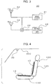
- Fig. 3 is a diagram illustrating the specific configuration of the radar 20.
- the radar 20 includes a signal source 21 that generates a signal of a predetermined frequency, a transmitting antenna (TX) 22 that transmits a radio wave corresponding to this signal to each reflective member 12 of the reflective sheet 10, a receiving antenna (RX) 23 that receives a reflected wave reflected by each reflective member 12 corresponding to this signal, a mixer 24 that mixes the transmitted signal and the received signal, and a distance calculation unit 25 that calculates the distance to each reflective member 12 by detecting the time until the radio wave transmitted from the radar 20 is reflected by each reflective member 12 back to the radar 20 on the basis of the output of the mixer 24.
- the signal source 21 and the transmitting antenna 22 correspond to a transmission unit that transmits a radio wave.
- the receiving antenna 23 and the mixer 24 correspond to a reception unit that receives the radio wave.
- An example of the radio waves transmitted and received by the radar 20 is a radio wave of a predetermined frequency that can pass through a human body, for example, millimeter waves. Specifically, a radio wave in a 27-GHz band or a 60-GHz band may be used.
- Fig. 4 is a diagram illustrating an example of the arrangement of the radar 20 and the reflective sheet 10.
- the reflective sheet 10 is disposed in each of a seat cushion 110 and a seat back 120 of a vehicle seat 100.
- the radar 20 that transmits and receives radio waves to and from the two reflective sheets 10 is disposed in common on the ceiling 200 of the vehicle.
- the radar 20 may be provided for each of the two reflective sheets 10 to transmit and receive radio waves.
- the displacement-distribution measuring unit 30 obtains the distance from the radar 20 to each reflective member 12 at a predetermined cycle to measure the displacement (displacement distribution) of each reflective member 12. The difference between the preceding distance to each reflective member 12 and the present distance is the displacement of one cycle of measurement, and its cumulative value is the displacement of all of the reflective members 12. In this embodiment, the displacement is obtained.
- the pressure (pressure distribution) may be obtained using the young's moduli of the seat cushion 110, the seat back 120, and the reflective sheet 10.
- the displacement measuring apparatus 1 of this embodiment can measure the displacements (pressurizations) of multiple portions according to the load exerted on the detection target by transmitting and receiving radio waves to and from the plurality of reflective members 12 disposed in the detection target to detect the distance to each reflective member 12, and moreover, does not need complicated wiring because there is no need to extract signals from the detection target via cables.
- arranging the plurality of reflective members 12 at regular intervals prevents deterioration in measurement quality due to uneven intervals of the measurement portions.
- the reflective sheet 10 is used in which all of the plurality of reflective members 12 are covered with a flexible sheet-like material, and the Poisson's ratio of the material that fills the gap between the plurality of reflective members 12 is set at a predetermined value or greater. This prevents the displacement of each reflective member 12 from influencing the displacement of the other reflective members 12, increasing the accuracy of displacement measurement by achieving independent displacement of each reflective member 12.
- millimeter waves specifically, in a 27-GHz band or a 60-GHz band, as the radio waves of a predetermined frequency to be transmitted to and received from the radar 20 allows measurement of displacement, with a person seated on the detection target.
- the reflective members 12 are made of an electrically conductive material with an electrical conductivity of a predetermined value or greater or a magnetic material with a magnetic permeability of predetermined value or greater.
- the radio wave transmission depth L in the surface of the reflective member 12 is expressed as ⁇ (2/ ⁇ ), where ⁇ is the magnetic permeability of the material, ⁇ is the electrical conductivity of the material, and ⁇ is the frequency of the radio wave. Accordingly, the transmission depth L can be decreased to make it easy to reflect radio waves by increasing the electrical conductivity or the magnetic permeability of the reflective member 12.
- Using the seat 100 ( Fig. 4 ) of a vehicle as the detection target, and disposing the radar 20 on the ceiling 200 ( Fig. 4 ) of the vehicle allows easily measuring the displacement distribution when an occupant is seated on the vehicle seat 100 with a complicated shape without cumbersome wiring.
- the present invention is not limited to the above embodiment, and various modifications are possible within the scope of the present invention.
- the present invention can also be applied to any other targets other than the seat the displacement distribution or the pressure distribution of which is to be measured.
- the present invention can also be applied measurement of the displacement distribution or the pressure distribution of an area to which a load is applied, such as a bed and an arm rest.
- the present invention can also be applied to determination of the barycentric position of the sole of the foot by measuring the displacement distribution or the pressure distribution.
- the present invention allows measuring the displacements (pressurizations) of multiple portions according to the load exerted on a detection target by transmitting and receiving radio waves to and from a plurality of reflective members disposed in the detection target to detect the distance to each reflective member, and moreover, does not need complicated wiring because there is no need to extract signals from the detection target via cables.
Landscapes
- Engineering & Computer Science (AREA)
- Remote Sensing (AREA)
- Radar, Positioning & Navigation (AREA)
- Computer Networks & Wireless Communication (AREA)
- Physics & Mathematics (AREA)
- General Physics & Mathematics (AREA)
- Mechanical Engineering (AREA)
- Transportation (AREA)
- Aviation & Aerospace Engineering (AREA)
- Electromagnetism (AREA)
- Seats For Vehicles (AREA)
- Radar Systems Or Details Thereof (AREA)
- Measurement Of Length, Angles, Or The Like Using Electric Or Magnetic Means (AREA)
Abstract
Description
- The present invention relates to a displacement measuring apparatus that measures the displacement of multiple portions.
- There are known seat devices (for example, see
JP 2018- 102830 A JP 2018-165135 A - The output of the pressure-sensitive cells and the pressure sensors used in the seat device disclosed in
JP 2018-102830 A JP 2018-165135 A - Accordingly, it is an object of the present invention to provide a displacement measuring apparatus that does not need complicated wiring for measuring the pressurization (displacement) of multiple portions according to the load.
- The present invention relates to a displacement measuring apparatus according to the appended claims. Embodiments are disclosed in the dependent claims. A displacement measuring apparatus according an aspect of the present invention includes a plurality of reflective members disposed at a detection target, a transmission unit configured to transmit a radio wave of a predetermined frequency that can pass through a human body to each of the plurality of reflective members, a receiving unit configured to receive the radio wave of the predetermined frequency reflected by each of the plurality of reflective members and returned, a distance calculation unit configured to calculate information on distances to the plurality of reflective members based on information on a time until the radio wave transmitted from the transmission unit returns to the receiving unit, and a displacement calculation unit configured to calculate a displacement of each of the plurality of reflective members based on the information on the distances.
- This allows measuring the displacements (pressurizations) of multiple portions according to the load exerted on the detection target by transmitting and receiving radio waves to and from the plurality of reflective members disposed at the detection target to detect the distance to each reflective member, and moreover, eliminates the need for complicated wiring because there is no need to extract signals from the detection target via cables.
- The plurality of reflective members are preferably disposed at regular intervals. This prevents deterioration in measurement quality due to uneven intervals of the measurement portions.
- All of the plurality of reflective members are preferably covered with a sheet-like flexible material. The material filling gaps between the plurality of reflective members preferably has a Poisson's ratio of a predetermined value or greater. This prevents the displacement of each reflective member from influencing the displacement of the other reflective members, increasing the accuracy of displacement measurement by achieving independent displacement of each reflective member.
- The radio wave of the predetermined frequency is preferably a millimeter wave. The radio wave of the predetermined frequency is preferably a radio wave in a 27-GHz band or a 60-GHz band. This allows measurement of displacement, with a person seated on the detection target.
- Each of the reflective members is preferably an electrically conductive material with a conductivity of a predetermined value or greater. Each of the reflective members is preferably a magnetic material with a magnetic permeability of a predetermined value or greater. The radio wave transmission depth L in the surface of the reflective member is expressed as √(2/µσω), where µ is the magnetic permeability of the material, σ is the electrical conductivity of the material, and ω is the frequency of the radio wave. Accordingly, the transmission depth L can be decreased to make it easy to reflect radio waves by increasing the electrical conductivity and/or the magnetic permeability of the reflective member.
- The detection target is preferably a seat of a vehicle, and the transmission unit and the receiving unit are preferably disposed at a ceiling of the vehicle. This configuration allows easily measuring the displacement distribution when an occupant seated is on the vehicle seat with a complicated shape without cumbersome wiring.
-
Fig. 1 is a diagram showing the configuration of a displacement measuring apparatus according to an embodiment of the present invention; -
Fig. 2A is a plan view of an example of a reflective sheet according to an embodiment of the present invention; -
Fig. 2B is a cross-sectional view of the reflective sheet; -
Fig. 3 is a diagram illustrating the specific configuration of a radar according to an embodiment of the present invention; and -
Fig. 4 is a diagram illustrating an example of the arrangement of the radar and the reflective sheet. - A displacement measuring apparatus according to embodiments of the present invention will be described hereinbelow with reference to the drawings.
-
Fig. 1 is a diagram showing the configuration of a displacement measuring apparatus according to an embodiment of the present invention. Thedisplacement measuring apparatus 1 of this embodiment shown inFig. 1 is for measuring the displacement distribution of the seat of a vehicle (detection target), with an occupant, such as a driver, seated. To this end, thedisplacement measuring apparatus 1 includes areflective sheet 10 in which a plurality ofreflective members 12 are embedded, aradar 20, and a displacement-distribution measuring unit 30. - The
reflective sheet 10 is made of a sheet-like flexible material with a Poisson ratio equal to or higher than a predetermined value and includes therein a plurality ofreflective members 12 arranged at regular intervals. -
Figs. 2A and 2B are diagrams illustrating an example of thereflective sheet 10.Fig. 2A is a plan view, andFig. 2B is a cross-sectional view of thereflective sheet 10. As illustrated in the drawings, thereflective sheet 10 has therein a total of 25reflective members 12 in five rows and five columns. Eachreflective member 12 is formed of an electrically conductive material and/or a magnetic material having a rectangular shape, for example, with a side of 11 mm. - The radio wave transmission depth L in the surface of the
reflective member 12 is generally expressed as √(2/µσω), where µ is the magnetic permeability of the material, σ is the electrical conductivity of the material, and ω is the frequency of the radio wave. Accordingly, the transmission depth L can be decreased to make it easy to reflect radio waves by increasing the electrical conductivity σ or the magnetic permeability µ of thereflective member 12. In this embodiment, thereflective member 12 is made of an electrically conductive material with an electrical conductivity of σ1 or higher and/or a magnetic material with a magnetic permeability of µ1 or higher. Specific values of σ1 and µ1 may be determined in designing the product on the basis of the frequency, the intensity of the radio wave used, and the distance between theradar 20 and eachreflective member 12. - The
radar 20 detects the distances to the plurality ofreflective members 12 using a radio wave of a predetermined frequency.Fig. 3 is a diagram illustrating the specific configuration of theradar 20. As illustrated inFig. 3 , theradar 20 includes asignal source 21 that generates a signal of a predetermined frequency, a transmitting antenna (TX) 22 that transmits a radio wave corresponding to this signal to eachreflective member 12 of thereflective sheet 10, a receiving antenna (RX) 23 that receives a reflected wave reflected by eachreflective member 12 corresponding to this signal, amixer 24 that mixes the transmitted signal and the received signal, and adistance calculation unit 25 that calculates the distance to eachreflective member 12 by detecting the time until the radio wave transmitted from theradar 20 is reflected by eachreflective member 12 back to theradar 20 on the basis of the output of themixer 24. Thesignal source 21 and the transmittingantenna 22 correspond to a transmission unit that transmits a radio wave. The receivingantenna 23 and themixer 24 correspond to a reception unit that receives the radio wave. - An example of the radio waves transmitted and received by the
radar 20 is a radio wave of a predetermined frequency that can pass through a human body, for example, millimeter waves. Specifically, a radio wave in a 27-GHz band or a 60-GHz band may be used. -
Fig. 4 is a diagram illustrating an example of the arrangement of theradar 20 and thereflective sheet 10. InFig. 4 , thereflective sheet 10 is disposed in each of aseat cushion 110 and a seat back 120 of avehicle seat 100. Theradar 20 that transmits and receives radio waves to and from the tworeflective sheets 10 is disposed in common on theceiling 200 of the vehicle. Theradar 20 may be provided for each of the tworeflective sheets 10 to transmit and receive radio waves. - The displacement-distribution measuring
unit 30 obtains the distance from theradar 20 to eachreflective member 12 at a predetermined cycle to measure the displacement (displacement distribution) of eachreflective member 12. The difference between the preceding distance to eachreflective member 12 and the present distance is the displacement of one cycle of measurement, and its cumulative value is the displacement of all of thereflective members 12. In this embodiment, the displacement is obtained. Alternatively, the pressure (pressure distribution) may be obtained using the young's moduli of theseat cushion 110, theseat back 120, and thereflective sheet 10. - Thus, the
displacement measuring apparatus 1 of this embodiment can measure the displacements (pressurizations) of multiple portions according to the load exerted on the detection target by transmitting and receiving radio waves to and from the plurality ofreflective members 12 disposed in the detection target to detect the distance to eachreflective member 12, and moreover, does not need complicated wiring because there is no need to extract signals from the detection target via cables. - Furthermore, arranging the plurality of
reflective members 12 at regular intervals prevents deterioration in measurement quality due to uneven intervals of the measurement portions. - The
reflective sheet 10 is used in which all of the plurality ofreflective members 12 are covered with a flexible sheet-like material, and the Poisson's ratio of the material that fills the gap between the plurality ofreflective members 12 is set at a predetermined value or greater. This prevents the displacement of eachreflective member 12 from influencing the displacement of the otherreflective members 12, increasing the accuracy of displacement measurement by achieving independent displacement of eachreflective member 12. - Using millimeter waves, specifically, in a 27-GHz band or a 60-GHz band, as the radio waves of a predetermined frequency to be transmitted to and received from the
radar 20 allows measurement of displacement, with a person seated on the detection target. - Furthermore, the
reflective members 12 are made of an electrically conductive material with an electrical conductivity of a predetermined value or greater or a magnetic material with a magnetic permeability of predetermined value or greater. The radio wave transmission depth L in the surface of thereflective member 12 is expressed as √(2/µσω), where µ is the magnetic permeability of the material, σ is the electrical conductivity of the material, and ω is the frequency of the radio wave. Accordingly, the transmission depth L can be decreased to make it easy to reflect radio waves by increasing the electrical conductivity or the magnetic permeability of thereflective member 12. - Using the seat 100 (
Fig. 4 ) of a vehicle as the detection target, and disposing theradar 20 on the ceiling 200 (Fig. 4 ) of the vehicle allows easily measuring the displacement distribution when an occupant is seated on thevehicle seat 100 with a complicated shape without cumbersome wiring. - It is to be understood that the present invention is not limited to the above embodiment, and various modifications are possible within the scope of the present invention. Although, in the above embodiment (
Fig. 4 ), the displacement of thevehicle seat 100 is measured, the present invention can also be applied to any other targets other than the seat the displacement distribution or the pressure distribution of which is to be measured. For example, the present invention can also be applied measurement of the displacement distribution or the pressure distribution of an area to which a load is applied, such as a bed and an arm rest. The present invention can also be applied to determination of the barycentric position of the sole of the foot by measuring the displacement distribution or the pressure distribution. - Thus, the present invention allows measuring the displacements (pressurizations) of multiple portions according to the load exerted on a detection target by transmitting and receiving radio waves to and from a plurality of reflective members disposed in the detection target to detect the distance to each reflective member, and moreover, does not need complicated wiring because there is no need to extract signals from the detection target via cables.
Claims (9)
- A displacement measuring apparatus (1) comprising:a plurality of reflective members (12) disposed at a detection target;a transmission unit (21, 22) configured to transmit a radio wave of a predetermined frequency that can pass through a human body to each of the plurality of reflective members (12);a receiving unit (23, 24) configured to receive the radio wave of the predetermined frequency reflected by each of the plurality of reflective members (12) and returned;a distance calculation unit (25) configured to calculate information on distances to the plurality of reflective members (12) based on information on a time until the radio wave transmitted from the transmission unit (21, 22) returns to the receiving unit (23, 24); anda displacement calculation unit (30) configured to calculate a displacement of each of the plurality of reflective members (12) based on the information on the distances.
- The displacement measuring apparatus (1) according to Claim 1, wherein the plurality of reflective members (12) are disposed at regular intervals.
- The displacement measuring apparatus (1) according to Claim 1 or 2, wherein all of the plurality of reflective members (12) are covered with a sheet-like flexible material.
- The displacement measuring apparatus (1) according to Claim 3, wherein the material filling gaps between the plurality of reflective members (12) has a Poisson's ratio of a predetermined value or greater.
- The displacement measuring apparatus (1) according to any one of Claims 1 to 4, wherein the radio wave of the predetermined frequency comprises a millimeter wave.
- The displacement measuring apparatus (1) according to Claim 5, wherein the radio wave of the predetermined frequency comprises a radio wave in a 27-GHz band or a 60-GHz band.
- The displacement measuring apparatus (1) according to one of Claims 1 - 6, wherein the reflective members (12) comprise an electrically conductive material with a conductivity of a predetermined value or greater.
- The displacement measuring apparatus (1) according to one of Claims 1 - 7, wherein the reflective members (12) comprise a magnetic material with a magnetic permeability of a predetermined value or greater.
- The displacement measuring apparatus (1) according to one of Claims 1 - 8,
wherein the detection target comprises a seat of a vehicle, and
wherein the transmission unit (21, 22) and the receiving unit (23, 24) are disposed at a ceiling of the vehicle.
Applications Claiming Priority (1)
| Application Number | Priority Date | Filing Date | Title |
|---|---|---|---|
| JP2020050334A JP7341616B2 (en) | 2020-03-20 | 2020-03-20 | displacement measuring device |
Publications (1)
| Publication Number | Publication Date |
|---|---|
| EP3882660A1 true EP3882660A1 (en) | 2021-09-22 |
Family
ID=74844757
Family Applications (1)
| Application Number | Title | Priority Date | Filing Date |
|---|---|---|---|
| EP21159824.8A Pending EP3882660A1 (en) | 2020-03-20 | 2021-03-01 | Displacement measuring apparatus |
Country Status (4)
| Country | Link |
|---|---|
| US (1) | US20210293945A1 (en) |
| EP (1) | EP3882660A1 (en) |
| JP (1) | JP7341616B2 (en) |
| CN (1) | CN113495265A (en) |
Citations (5)
| Publication number | Priority date | Publication date | Assignee | Title |
|---|---|---|---|---|
| US20050285736A1 (en) * | 2002-11-20 | 2005-12-29 | Siemens Aktiengesellschaft | System and method for recognition of seat occupancy in a vehicle |
| US20080001846A1 (en) * | 2004-09-23 | 2008-01-03 | Siemens Aktiengesellschaft | Method for Evaluating Reflector Answer Signals of a System for Recognizing the Occupancy of a Seat |
| JP2018102830A (en) | 2016-12-28 | 2018-07-05 | 株式会社槌屋 | Sheet device |
| JP2018165135A (en) | 2017-03-28 | 2018-10-25 | テイ・エス テック株式会社 | Sheet for vehicle |
| US20190056276A1 (en) * | 2017-08-18 | 2019-02-21 | Google Llc | Radar-Based Force Sensing |
Family Cites Families (9)
| Publication number | Priority date | Publication date | Assignee | Title |
|---|---|---|---|---|
| JP3171030B2 (en) * | 1994-10-28 | 2001-05-28 | トヨタ自動車株式会社 | Occupant detection device and auxiliary device control device using the same |
| JP3838815B2 (en) * | 1999-05-10 | 2006-10-25 | 日本電気株式会社 | Mobile phone |
| JP3621679B2 (en) | 2001-12-28 | 2005-02-16 | 三菱電機株式会社 | Vehicle interior object detection device |
| US7084836B2 (en) * | 2003-05-15 | 2006-08-01 | Espenscheid Mark W | Flat panel antenna array |
| DE10341578B4 (en) | 2003-09-09 | 2008-02-07 | Siemens Ag | Device and method for recognizing an object or a person on a seat of a means of transport |
| JP2019168379A (en) * | 2018-03-26 | 2019-10-03 | アイシン精機株式会社 | Living body detection system |
| US11378671B1 (en) * | 2018-08-16 | 2022-07-05 | Edge 3 Technologies | Coarse to fine movement detection in vehicles |
| US20200249337A1 (en) * | 2019-01-31 | 2020-08-06 | Novelic D.O.O. | Radar based inverse detection sensor system |
| US11543511B2 (en) * | 2019-03-11 | 2023-01-03 | Panasonic Intellectual Property Management Co., Ltd. | Radar apparatus and vehicle |
-
2020
- 2020-03-20 JP JP2020050334A patent/JP7341616B2/en active Active
-
2021
- 2021-02-04 US US17/167,274 patent/US20210293945A1/en not_active Abandoned
- 2021-03-01 EP EP21159824.8A patent/EP3882660A1/en active Pending
- 2021-03-15 CN CN202110274299.XA patent/CN113495265A/en active Pending
Patent Citations (5)
| Publication number | Priority date | Publication date | Assignee | Title |
|---|---|---|---|---|
| US20050285736A1 (en) * | 2002-11-20 | 2005-12-29 | Siemens Aktiengesellschaft | System and method for recognition of seat occupancy in a vehicle |
| US20080001846A1 (en) * | 2004-09-23 | 2008-01-03 | Siemens Aktiengesellschaft | Method for Evaluating Reflector Answer Signals of a System for Recognizing the Occupancy of a Seat |
| JP2018102830A (en) | 2016-12-28 | 2018-07-05 | 株式会社槌屋 | Sheet device |
| JP2018165135A (en) | 2017-03-28 | 2018-10-25 | テイ・エス テック株式会社 | Sheet for vehicle |
| US20190056276A1 (en) * | 2017-08-18 | 2019-02-21 | Google Llc | Radar-Based Force Sensing |
Also Published As
| Publication number | Publication date |
|---|---|
| CN113495265A (en) | 2021-10-12 |
| JP2021146952A (en) | 2021-09-27 |
| US20210293945A1 (en) | 2021-09-23 |
| JP7341616B2 (en) | 2023-09-11 |
Similar Documents
| Publication | Publication Date | Title |
|---|---|---|
| EP3080867B1 (en) | Radar sensor with frequency dependent beam steering | |
| EP1342627B1 (en) | Sensing of seat occupant weight by cushion deformation | |
| US20190391249A1 (en) | Sensor device and system, and biometric sensing method and system | |
| JP4482785B2 (en) | Vehicle occupant determination device | |
| JP6491254B2 (en) | Antenna device and radar device | |
| US7193930B2 (en) | Quantitative echo sounder and method of quantitative sounding of fish | |
| GB2360097A (en) | Apparatus and method for measuring weight of an occupying item of a seat | |
| KR20140140331A (en) | Ultrasound system and method for detecting pressure applied to living body | |
| CN112136060A (en) | MIMO radar sensor for motor vehicles | |
| JP2012098107A (en) | Radar apparatus | |
| CN112513667B (en) | Radar device | |
| JP2016198121A (en) | Biological information detection device and seat with biological information detection device | |
| WO2021205769A1 (en) | Radar device, and vehicle and position detection device provided with same | |
| LU101570B1 (en) | Method for Occupancy Detection | |
| CN116848426A (en) | Radio wave sensors and passenger detection devices | |
| US10758178B2 (en) | Measuring method of human body | |
| EP3882660A1 (en) | Displacement measuring apparatus | |
| US10893386B2 (en) | Mobile terminal position detecting device | |
| EP2281509B1 (en) | Setting a Sagittal View in an Ultrasound System | |
| JP6499217B2 (en) | Antenna device and radar device | |
| US20140309516A1 (en) | Photoacoustic wave measurement instrument | |
| CN109863421B (en) | Signal processing device, radar device and signal processing method | |
| EP3328558B1 (en) | Extended range ultrasound transducer | |
| US20130128698A1 (en) | Object Outline Measuring System | |
| JP3621679B2 (en) | Vehicle interior object detection device |
Legal Events
| Date | Code | Title | Description |
|---|---|---|---|
| PUAI | Public reference made under article 153(3) epc to a published international application that has entered the european phase |
Free format text: ORIGINAL CODE: 0009012 |
|
| STAA | Information on the status of an ep patent application or granted ep patent |
Free format text: STATUS: THE APPLICATION HAS BEEN PUBLISHED |
|
| AK | Designated contracting states |
Kind code of ref document: A1 Designated state(s): AL AT BE BG CH CY CZ DE DK EE ES FI FR GB GR HR HU IE IS IT LI LT LU LV MC MK MT NL NO PL PT RO RS SE SI SK SM TR |
|
| STAA | Information on the status of an ep patent application or granted ep patent |
Free format text: STATUS: REQUEST FOR EXAMINATION WAS MADE |
|
| 17P | Request for examination filed |
Effective date: 20220316 |
|
| RBV | Designated contracting states (corrected) |
Designated state(s): AL AT BE BG CH CY CZ DE DK EE ES FI FR GB GR HR HU IE IS IT LI LT LU LV MC MK MT NL NO PL PT RO RS SE SI SK SM TR |
|
| STAA | Information on the status of an ep patent application or granted ep patent |
Free format text: STATUS: EXAMINATION IS IN PROGRESS |
|
| 17Q | First examination report despatched |
Effective date: 20240516 |