EP3882650A1 - Squint-offsetting radar mounting tab caps - Google Patents
Squint-offsetting radar mounting tab caps Download PDFInfo
- Publication number
- EP3882650A1 EP3882650A1 EP21162210.5A EP21162210A EP3882650A1 EP 3882650 A1 EP3882650 A1 EP 3882650A1 EP 21162210 A EP21162210 A EP 21162210A EP 3882650 A1 EP3882650 A1 EP 3882650A1
- Authority
- EP
- European Patent Office
- Prior art keywords
- mounting
- radar device
- pair
- radar
- squint angle
- Prior art date
- Legal status (The legal status is an assumption and is not a legal conclusion. Google has not performed a legal analysis and makes no representation as to the accuracy of the status listed.)
- Granted
Links
Images


Classifications
-
- G—PHYSICS
- G01—MEASURING; TESTING
- G01S—RADIO DIRECTION-FINDING; RADIO NAVIGATION; DETERMINING DISTANCE OR VELOCITY BY USE OF RADIO WAVES; LOCATING OR PRESENCE-DETECTING BY USE OF THE REFLECTION OR RERADIATION OF RADIO WAVES; ANALOGOUS ARRANGEMENTS USING OTHER WAVES
- G01S7/00—Details of systems according to groups G01S13/00, G01S15/00, G01S17/00
- G01S7/02—Details of systems according to groups G01S13/00, G01S15/00, G01S17/00 of systems according to group G01S13/00
- G01S7/03—Details of HF subsystems specially adapted therefor, e.g. common to transmitter and receiver
-
- G—PHYSICS
- G01—MEASURING; TESTING
- G01S—RADIO DIRECTION-FINDING; RADIO NAVIGATION; DETERMINING DISTANCE OR VELOCITY BY USE OF RADIO WAVES; LOCATING OR PRESENCE-DETECTING BY USE OF THE REFLECTION OR RERADIATION OF RADIO WAVES; ANALOGOUS ARRANGEMENTS USING OTHER WAVES
- G01S7/00—Details of systems according to groups G01S13/00, G01S15/00, G01S17/00
- G01S7/02—Details of systems according to groups G01S13/00, G01S15/00, G01S17/00 of systems according to group G01S13/00
-
- G—PHYSICS
- G01—MEASURING; TESTING
- G01S—RADIO DIRECTION-FINDING; RADIO NAVIGATION; DETERMINING DISTANCE OR VELOCITY BY USE OF RADIO WAVES; LOCATING OR PRESENCE-DETECTING BY USE OF THE REFLECTION OR RERADIATION OF RADIO WAVES; ANALOGOUS ARRANGEMENTS USING OTHER WAVES
- G01S13/00—Systems using the reflection or reradiation of radio waves, e.g. radar systems; Analogous systems using reflection or reradiation of waves whose nature or wavelength is irrelevant or unspecified
- G01S13/88—Radar or analogous systems specially adapted for specific applications
- G01S13/93—Radar or analogous systems specially adapted for specific applications for anti-collision purposes
- G01S13/931—Radar or analogous systems specially adapted for specific applications for anti-collision purposes of land vehicles
-
- H—ELECTRICITY
- H01—ELECTRIC ELEMENTS
- H01Q—ANTENNAS, i.e. RADIO AERIALS
- H01Q1/00—Details of, or arrangements associated with, antennas
- H01Q1/12—Supports; Mounting means
- H01Q1/125—Means for positioning
-
- H—ELECTRICITY
- H01—ELECTRIC ELEMENTS
- H01Q—ANTENNAS, i.e. RADIO AERIALS
- H01Q1/00—Details of, or arrangements associated with, antennas
- H01Q1/27—Adaptation for use in or on movable bodies
- H01Q1/32—Adaptation for use in or on road or rail vehicles
- H01Q1/3208—Adaptation for use in or on road or rail vehicles characterised by the application wherein the antenna is used
- H01Q1/3233—Adaptation for use in or on road or rail vehicles characterised by the application wherein the antenna is used particular used as part of a sensor or in a security system, e.g. for automotive radar, navigation systems
-
- H—ELECTRICITY
- H01—ELECTRIC ELEMENTS
- H01Q—ANTENNAS, i.e. RADIO AERIALS
- H01Q3/00—Arrangements for changing or varying the orientation or the shape of the directional pattern of the waves radiated from an antenna or antenna system
- H01Q3/02—Arrangements for changing or varying the orientation or the shape of the directional pattern of the waves radiated from an antenna or antenna system using mechanical movement of antenna or antenna system as a whole
- H01Q3/04—Arrangements for changing or varying the orientation or the shape of the directional pattern of the waves radiated from an antenna or antenna system using mechanical movement of antenna or antenna system as a whole for varying one co-ordinate of the orientation
- H01Q3/06—Arrangements for changing or varying the orientation or the shape of the directional pattern of the waves radiated from an antenna or antenna system using mechanical movement of antenna or antenna system as a whole for varying one co-ordinate of the orientation over a restricted angle
-
- G—PHYSICS
- G01—MEASURING; TESTING
- G01S—RADIO DIRECTION-FINDING; RADIO NAVIGATION; DETERMINING DISTANCE OR VELOCITY BY USE OF RADIO WAVES; LOCATING OR PRESENCE-DETECTING BY USE OF THE REFLECTION OR RERADIATION OF RADIO WAVES; ANALOGOUS ARRANGEMENTS USING OTHER WAVES
- G01S13/00—Systems using the reflection or reradiation of radio waves, e.g. radar systems; Analogous systems using reflection or reradiation of waves whose nature or wavelength is irrelevant or unspecified
- G01S13/88—Radar or analogous systems specially adapted for specific applications
- G01S13/93—Radar or analogous systems specially adapted for specific applications for anti-collision purposes
- G01S13/931—Radar or analogous systems specially adapted for specific applications for anti-collision purposes of land vehicles
- G01S2013/9327—Sensor installation details
- G01S2013/93271—Sensor installation details in the front of the vehicles
-
- G—PHYSICS
- G01—MEASURING; TESTING
- G01S—RADIO DIRECTION-FINDING; RADIO NAVIGATION; DETERMINING DISTANCE OR VELOCITY BY USE OF RADIO WAVES; LOCATING OR PRESENCE-DETECTING BY USE OF THE REFLECTION OR RERADIATION OF RADIO WAVES; ANALOGOUS ARRANGEMENTS USING OTHER WAVES
- G01S7/00—Details of systems according to groups G01S13/00, G01S15/00, G01S17/00
- G01S7/02—Details of systems according to groups G01S13/00, G01S15/00, G01S17/00 of systems according to group G01S13/00
- G01S7/027—Constructional details of housings, e.g. form, type, material or ruggedness
Definitions
- the present disclosure generally relates to radar devices and, more particularly, to systems and methods for offsetting a squint angle when mounting a radar device.
- a radar device is configured to transmit and receive electromagnetic waves.
- the electromagnetic waves are transmitted by a transmitter of the radar device at an angle that is offset from a normal of a plane of an antenna of the radar device. This offset angle is also known as a squint angle.
- the squint angle of a radar device could be due to a variety of factors, including, but not limited to, operating frequency, polarization, and orientation. If unaccounted for, the squint angle could negatively impact operation of the radar device (e.g., decreased bandwidth). For vehicle applications, this could be particularly problematic as radar devices are often utilized for detection of other vehicles or objects.
- the radar system comprises: a radar device defining upper and lower pairs of mounting tabs and being configured to transmit and receive electromagnetic waves based on a squint angle, a mounting device configured to be attached to a surface and to receive the radar device, wherein the mounting device defines upper and lower pairs of connection position assurance (CPA) features that correspond to the upper and lower pairs of mounting tabs, and a pair of mounting tab caps configured to be selectively installed on the upper or lower pairs of mounting tabs to offset the squint angle of the radar device.
- CCA connection position assurance
- the pair of mounting tab caps are configured to be installed on the upper pair of mounting tabs to offset a negative or downward squint angle of the radar device. In some implementations, the pair of mounting tab caps are configured to be installed on the lower pair of mounting tabs to offset a positive or upward squint angle of the radar device. In some implementations, the pair of mounting tab caps are configured to not be installed on either the upper or lower mounting tabs when a magnitude of the squint angle of the radar device is less than a predetermined threshold.
- the upper and lower pairs of CPA features are spring clips.
- the pair of mounting tab caps are configured to be installed on the upper or lower mounting tabs prior to inserting the radar device into the mounting device.
- the squint angle of the radar device is predetermined.
- the mounting device is formed of a plastic material.
- the surface is a surface proximate to a front portion of a vehicle and the radar device is a front-facing radar device.
- a method of installing a radar system comprises: obtaining a radar device defining upper and lower pairs of mounting tabs and being configured to transmit and receive electromagnetic waves based on a squint angle, obtaining a mounting device configured to receive the radar device and defining upper and lower pairs of connection position assurance (CPA) features that correspond to the upper and lower pairs of mounting tabs, attaching the mounting device to a surface, selective installing a pair of mounting tab caps on the upper or lower pairs of mounting tabs to offset the squint angle of the radar device, and inserting the radar device into the mounting device.
- CPA connection position assurance
- the pair of mounting tab caps are installed on the upper pair of mounting tabs to offset a negative or downward squint angle of the radar device. In some implementations, the pair of mounting tab caps are installed on the lower pair of mounting tabs to offset a positive or upward squint angle of the radar device. In some implementations, the pair of mounting tab caps are not installed on either the upper or lower mounting tabs when a magnitude of the squint angle of the radar device is less than a predetermined threshold.
- the upper and lower pairs of CPA features are spring clips.
- the pair of mounting tab caps are installed on the upper or lower mounting tabs prior to inserting the radar device into the mounting device.
- the method further comprises predetermining the squint angle of the radar device.
- the mounting device is formed of a plastic material.
- the surface is a surface proximate to a front portion of a vehicle and the radar device is a front-facing radar device.
- the radar system comprises: a radar means for transmitting and receiving electromagnetic waves based on a squint angle, the radar means defining upper and lower pairs of mounting feature means, a mounting means for attachment to a surface and for receiving the radar means, the mounting means defining upper and lower pairs of connection position assurance (CPA) feature means that correspond to the upper and lower pairs of mounting feature means, and a pair of mounting feature cap means for selective installation on the upper or lower pairs of mounting feature means to offset the squint angle of the radar means.
- CCA connection position assurance
- the pair of mounting feature cap means are for installation on the upper pair of mounting feature means to offset a negative or downward squint angle of the radar means, and the pair of mounting feature cap means are for installation on the lower pair of mounting feature means to offset a positive or upward squint angle of the radar means.
- the radar system comprises a radar device 100 comprising a housing 104 that houses electronic components (not shown) of the radar device 100.
- These electronic components include, but are not limited to, a transmitter and an antenna or receiver.
- the antenna is arranged parallel to a plane defined by a front surface 108 of the housing 104.
- the transmitter may transmit electromagnetic waves based on a squint angle relative to the plane defined by the front surface 108 of the housing 104.
- the electronic components (transmitter, antenna, etc.) are electrically connected to one or more other systems (e.g., a vehicle controller) via electrical connector 112.
- the housing 104 of the radar device 100 further defines an upper pair of mounting tabs 116a, 116b and a lower pair of mounting tabs 120a, 120b.
- a pair of mounting tab caps 124a, 124b are selectively installable either on the upper pair of mounting tabs 116a, 116b (as shown) or on the lower pair of mounting tabs 120a, 120b.
- these mounting tab caps 124a, 124b may securely engage connection position assurance (CPA) features 128 of the respective mounting tabs 116a, 116b, 120a, 120b.
- CCA connection position assurance
- mounting tabs 116a, 116b, 120a, 120b and the mounting tab caps 124a, 124b are merely exemplary and are not intended to limit the scope of the present disclosure. It will be appreciated that other suitable mounting features and mounting feature caps could be utilized in a similar manner to achieve the same goal of squint angle offsetting or compensation.
- the radar system further comprises a mounting device 150 that is configured to be attached to a surface.
- the mounting device 150 is attached to a surface proximate to a front portion of a vehicle (not shown), such as inside a front bumper or grill of the vehicle (e.g., for a front-facing application of the radar device 100).
- the mounting device 150 comprises a housing 154 that defines mounting features (e.g., screw holes) for attaching the mounting device 150 to the surface.
- the mounting device 150 is formed of one or more plastic materials (e.g., via injection molding), such as, but not limited to, polycarbonate (PC) or acrylonitrile butadiene styrene (ABS).
- PC polycarbonate
- ABS acrylonitrile butadiene styrene
- a plastic configuration of the mounting device 150 can provide for decreased costs and/or decreased weight, such as compared to metal configurations (e.g., a stamped metal mounting device).
- the housing 154 of the mounting device 150 generally defines a slot 162 for receiving the radar device 100.
- the housing 154 defines a first set of CPA features 166 (e.g., spring clips) for securely engaging a back surface of the radar device 100 and a second set of CPA features 170a, 170b, 174a, 174b (e.g., spring clips) for securely engaging the mounting tabs 116a, 116b, 120a, 120b of the radar device 100.
- This second set of CPA features 170a, 170b, 174a, 174b may also be described as an upper pair of CPA features 170a, 170b and a lower pair of CPA features 174a, 174b. Based on the selective installation of the mounting tab caps 124a, 124b, the radar device 100 is able to be tilted up or down to offset of compensate for its squint angle.
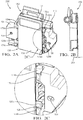
- the mounting tab caps 124a, 124b are installed on the upper pair of mounting tabs 116a, 116b, respectively.
- the radar device 100 i.e., the plane defined by its front surface 108
- This first configuration 200 can be utilized to offset or compensate for a negative or downward squint angle.
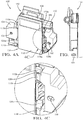
- the mounting tab caps 124a, 124b are not installed (see offset angle 304).
- This second configuration 300 can be utilized when a magnitude (absolute value) of the squint angle of the radar device 100 is less than a predetermined threshold.
- This predetermined threshold could be, for example, an acceptable squint angle for proper operation of the radar device 100.
- the mounting tab caps 124a, 124b are installed on the lower pair of mounting tabs 120a, 120b, respectively.
- the radar device 100 i.e., the plane defined by its front surface 108
- This third configuration 400 can be utilized to offset or compensate for a positive or upward squint angle.
- different sets or configurations for the mounting tab caps 124a, 124b could be utilized for installation on the upper pair of mounting tabs 116a, 116b compared to installation on the lower pair of mounting tabs 120a, 120b. This could provide for easier installation configuration verification by a human or robotic installer. It will also be appreciated that multiple sets of mounting tab caps 124a, 124b could be utilized to provide for even further squint angle offsetting or compensation. For example, two different sets of mounting tab caps 124a, 124b could be provided, each set having a different thickness, and only one (or both) pairs of mounting tab caps 124a, 124b could be selectively installed.
- a method of installing the radar system can include obtaining the radar device 100 and the mounting device 150.
- the method can also include determining the squint angle of the radar device 100. This squint angle could be predetermined, either by a manufacturer of the radar device 100 or via testing of the radar device 100. Based on the squint angle, the mounting tab caps 124a, 124b are selectively installed (upper, lower, or none) to offset or compensate for the squint angle of the radar device 100.
- the mounting device 150 is then attached to the surface (e.g., a surface proximate to front portion of a vehicle, not shown) and the radar device 100 is inserted into the mounting device 150 to complete the installation of the radar system. It will be appreciated that the radar device 100 could also be inserted into the mounting device 150 prior to attachment of the mounting device to the surface.
- the installation method could further include electrically connecting the radar device 100 via electrical connector 112 to another electrical system (e.g., a controller of the vehicle), which could then utilize measurements of the radar device 100 for various functionality (object/vehicle detection, adaptive cruise control, etc.). It will be appreciated that this installation method could be performed by a human installer, a robotic installer, or some combination thereof. For example only, the robotic installer could perform all of the above-described steps according to a set of instructions stored on a non-transitory computer-readable medium and executed by one or more processors.
- Example embodiments are provided so that this disclosure will be thorough, and will fully convey the scope to those who are skilled in the art. Numerous specific details are set forth such as examples of specific components, devices, and methods, to provide a thorough understanding of embodiments of the present disclosure. It will be apparent to those skilled in the art that specific details need not be employed, that example embodiments may be embodied in many different forms and that neither should be construed to limit the scope of the disclosure. In some example embodiments, well-known procedures, well-known device structures, and well-known technologies are not described in detail.
- first, second, third, etc. may be used herein to describe various elements, components, regions, layers and/or sections, these elements, components, regions, layers and/or sections should not be limited by these terms. These terms may be only used to distinguish one element, component, region, layer or section from another region, layer or section. Terms such as “first,” “second,” and other numerical terms when used herein do not imply a sequence or order unless clearly indicated by the context. Thus, a first element, component, region, layer or section discussed below could be termed a second element, component, region, layer or section without departing from the teachings of the example embodiments.
- module may refer to, be part of, or include: an Application Specific Integrated Circuit (ASIC); an electronic circuit; a combinational logic circuit; a field programmable gate array (FPGA); a processor or a distributed network of processors (shared, dedicated, or grouped) and storage in networked clusters or datacenters that executes code or a process; other suitable components that provide the described functionality; or a combination of some or all of the above, such as in a system-on-chip.
- the term module may also include memory (shared, dedicated, or grouped) that stores code executed by the one or more processors.
- code may include software, firmware, byte-code and/or microcode, and may refer to programs, routines, functions, classes, and/or objects.
- shared means that some or all code from multiple modules may be executed using a single (shared) processor. In addition, some or all code from multiple modules may be stored by a single (shared) memory.
- group means that some or all code from a single module may be executed using a group of processors. In addition, some or all code from a single module may be stored using a group of memories.
- the techniques described herein may be implemented by one or more computer programs executed by one or more processors.
- the computer programs include processor-executable instructions that are stored on a non-transitory tangible computer readable medium.
- the computer programs may also include stored data.
- Non-limiting examples of the non-transitory tangible computer readable medium are nonvolatile memory, magnetic storage, and optical storage.
- the present disclosure also relates to an apparatus for performing the operations herein.
- This apparatus may be specially constructed for the required purposes, or it may comprise a general-purpose computer selectively activated or reconfigured by a computer program stored on a computer readable medium that can be accessed by the computer.
- a computer program may be stored in a tangible computer readable storage medium, such as, but is not limited to, any type of disk including floppy disks, optical disks, CD-ROMs, magnetic-optical disks, read-only memories (ROMs), random access memories (RAMs), EPROMs, EEPROMs, magnetic or optical cards, application specific integrated circuits (ASICs), or any type of media suitable for storing electronic instructions, and each coupled to a computer system bus.
- the computers referred to in the specification may include a single processor or may be architectures employing multiple processor designs for increased computing capability.
- the present disclosure is well suited to a wide variety of computer network systems over numerous topologies.
- the configuration and management of large networks comprise storage devices and computers that are communicatively coupled to dissimilar computers and storage devices over a network, such as the Internet.
Landscapes
- Engineering & Computer Science (AREA)
- Radar, Positioning & Navigation (AREA)
- Remote Sensing (AREA)
- Physics & Mathematics (AREA)
- Computer Networks & Wireless Communication (AREA)
- General Physics & Mathematics (AREA)
- Electromagnetism (AREA)
- Computer Security & Cryptography (AREA)
- Radar Systems Or Details Thereof (AREA)
Abstract
Description
- The present disclosure generally relates to radar devices and, more particularly, to systems and methods for offsetting a squint angle when mounting a radar device.
- A radar device is configured to transmit and receive electromagnetic waves. In some radar device configurations (phased array, slotted waveguide, etc.), the electromagnetic waves are transmitted by a transmitter of the radar device at an angle that is offset from a normal of a plane of an antenna of the radar device. This offset angle is also known as a squint angle. The squint angle of a radar device could be due to a variety of factors, including, but not limited to, operating frequency, polarization, and orientation. If unaccounted for, the squint angle could negatively impact operation of the radar device (e.g., decreased bandwidth). For vehicle applications, this could be particularly problematic as radar devices are often utilized for detection of other vehicles or objects. Conventional radar device alignment systems and methods offset or compensate for the squint angle are complex and typically require multiple additional parts, such as a socket/nut/screw adjustment system and, in some cases, an additional adapter bracket. Accordingly, while these conventional radar device alignment systems and methods work well for their intended purpose, an opportunity exists for improvement in the relevant art.
- The background description provided herein is for the purpose of generally presenting the context of the disclosure. Work of the presently named inventors, to the extent it is described in this background section, as well as aspects of the description that may not otherwise qualify as prior art at the time of filing, are neither expressly nor impliedly admitted as prior art against the present disclosure.
- According to one aspect of the present disclosure, a radar system, is presented. In one exemplary implementation, the radar system comprises: a radar device defining upper and lower pairs of mounting tabs and being configured to transmit and receive electromagnetic waves based on a squint angle, a mounting device configured to be attached to a surface and to receive the radar device, wherein the mounting device defines upper and lower pairs of connection position assurance (CPA) features that correspond to the upper and lower pairs of mounting tabs, and a pair of mounting tab caps configured to be selectively installed on the upper or lower pairs of mounting tabs to offset the squint angle of the radar device.
- In some implementations, the pair of mounting tab caps are configured to be installed on the upper pair of mounting tabs to offset a negative or downward squint angle of the radar device. In some implementations, the pair of mounting tab caps are configured to be installed on the lower pair of mounting tabs to offset a positive or upward squint angle of the radar device. In some implementations, the pair of mounting tab caps are configured to not be installed on either the upper or lower mounting tabs when a magnitude of the squint angle of the radar device is less than a predetermined threshold.
- In some implementations, the upper and lower pairs of CPA features are spring clips. In some implementations, the pair of mounting tab caps are configured to be installed on the upper or lower mounting tabs prior to inserting the radar device into the mounting device. In some implementations, the squint angle of the radar device is predetermined. In some implementations, the mounting device is formed of a plastic material. In some implementations, the surface is a surface proximate to a front portion of a vehicle and the radar device is a front-facing radar device.
- According to another aspect of the present disclosure, a method of installing a radar system is presented. In one exemplary implementation, the method comprises: obtaining a radar device defining upper and lower pairs of mounting tabs and being configured to transmit and receive electromagnetic waves based on a squint angle, obtaining a mounting device configured to receive the radar device and defining upper and lower pairs of connection position assurance (CPA) features that correspond to the upper and lower pairs of mounting tabs, attaching the mounting device to a surface, selective installing a pair of mounting tab caps on the upper or lower pairs of mounting tabs to offset the squint angle of the radar device, and inserting the radar device into the mounting device.
- In some implementations, the pair of mounting tab caps are installed on the upper pair of mounting tabs to offset a negative or downward squint angle of the radar device. In some implementations, the pair of mounting tab caps are installed on the lower pair of mounting tabs to offset a positive or upward squint angle of the radar device. In some implementations, the pair of mounting tab caps are not installed on either the upper or lower mounting tabs when a magnitude of the squint angle of the radar device is less than a predetermined threshold.
- In some implementations, the upper and lower pairs of CPA features are spring clips. In some implementations, the pair of mounting tab caps are installed on the upper or lower mounting tabs prior to inserting the radar device into the mounting device. In some implementations, the method further comprises predetermining the squint angle of the radar device. In some implementations, the mounting device is formed of a plastic material. In some implementations, the surface is a surface proximate to a front portion of a vehicle and the radar device is a front-facing radar device.
- According to another aspect of the present disclosure, radar system, is presented. In one exemplary implementation, the radar system comprises: a radar means for transmitting and receiving electromagnetic waves based on a squint angle, the radar means defining upper and lower pairs of mounting feature means, a mounting means for attachment to a surface and for receiving the radar means, the mounting means defining upper and lower pairs of connection position assurance (CPA) feature means that correspond to the upper and lower pairs of mounting feature means, and a pair of mounting feature cap means for selective installation on the upper or lower pairs of mounting feature means to offset the squint angle of the radar means.
- In some implementations, the pair of mounting feature cap means are for installation on the upper pair of mounting feature means to offset a negative or downward squint angle of the radar means, and the pair of mounting feature cap means are for installation on the lower pair of mounting feature means to offset a positive or upward squint angle of the radar means.
- Further areas of applicability of the present disclosure will become apparent from the detailed description provided hereinafter. It should be understood that the detailed description and specific examples are intended for purposes of illustration only and are not intended to limit the scope of the disclosure.
- The present disclosure will become more fully understood from the detailed description and the accompanying drawings, wherein:
-
FIG. 1 illustrates an exploded view of a radar device, a mounting device, and a pair of mounting tab caps for offsetting a squint angle of the radar device according to some implementations of the present disclosure; -
FIGS. 2A-2C illustrate views of a first configuration of the radar device mounted in the mounting device with the mounting tab caps installed on an upper pair of mounting tabs of the radar device according to some implementations of the present disclosure; -
FIGS. 3A-3C illustrate views of a second configuration of the radar device mounted in the mounting device without the mounting tab caps installed according to some implementations of the present disclosure; and -
FIGS. 4A-4C illustrate views of a third configuration of the radar device mounted in the mounting device with the mounting tab caps installed on a lower pair of mounting tabs of the radar device according to some implementations of the present disclosure. - Referring now to
FIG. 1 , an exploded view of an example configuration of radar system according to some implementations of the present disclosure is illustrated. The radar system comprises aradar device 100 comprising ahousing 104 that houses electronic components (not shown) of theradar device 100. These electronic components include, but are not limited to, a transmitter and an antenna or receiver. The antenna is arranged parallel to a plane defined by afront surface 108 of thehousing 104. The transmitter, however, may transmit electromagnetic waves based on a squint angle relative to the plane defined by thefront surface 108 of thehousing 104. The electronic components (transmitter, antenna, etc.) are electrically connected to one or more other systems (e.g., a vehicle controller) viaelectrical connector 112. Thehousing 104 of theradar device 100 further defines an upper pair ofmounting tabs mounting tabs mounting tab caps mounting tabs mounting tabs mounting tab caps respective mounting tabs mounting tabs mounting tab caps - The radar system further comprises a
mounting device 150 that is configured to be attached to a surface. In one exemplary vehicle application, themounting device 150 is attached to a surface proximate to a front portion of a vehicle (not shown), such as inside a front bumper or grill of the vehicle (e.g., for a front-facing application of the radar device 100). More specifically, themounting device 150 comprises ahousing 154 that defines mounting features (e.g., screw holes) for attaching themounting device 150 to the surface. In one exemplary implementation, themounting device 150 is formed of one or more plastic materials (e.g., via injection molding), such as, but not limited to, polycarbonate (PC) or acrylonitrile butadiene styrene (ABS). A plastic configuration of themounting device 150 can provide for decreased costs and/or decreased weight, such as compared to metal configurations (e.g., a stamped metal mounting device). Thehousing 154 of themounting device 150 generally defines aslot 162 for receiving theradar device 100. Thehousing 154 defines a first set of CPA features 166 (e.g., spring clips) for securely engaging a back surface of theradar device 100 and a second set of CPA features 170a, 170b, 174a, 174b (e.g., spring clips) for securely engaging themounting tabs radar device 100. This second set of CPA features 170a, 170b, 174a, 174b may also be described as an upper pair of CPA features 170a, 170b and a lower pair of CPA features 174a, 174b. Based on the selective installation of themounting tab caps radar device 100 is able to be tilted up or down to offset of compensate for its squint angle. - In a
first configuration 200 inFIGS. 2A-2C , for example, the mountingtab caps tabs radar device 100 is subsequently inserted into the mountingdevice 150, the radar device 100 (i.e., the plane defined by its front surface 108) will be tilted upward (see offset angle 204). Thisfirst configuration 200 can be utilized to offset or compensate for a negative or downward squint angle. In asecond configuration 300 inFIGS. 3A-3C , the mountingtab caps second configuration 300 can be utilized when a magnitude (absolute value) of the squint angle of theradar device 100 is less than a predetermined threshold. This predetermined threshold could be, for example, an acceptable squint angle for proper operation of theradar device 100. In athird configuration 400 inFIGS. 4A-4C , the mountingtab caps tabs radar device 100 is subsequently inserted into the mountingdevice 150, the radar device 100 (i.e., the plane defined by its front surface 108) will be tilted downward (see offset angle 404). Thisthird configuration 400 can be utilized to offset or compensate for a positive or upward squint angle. In some implementations, different sets or configurations (different colors, different barcodes, etc.) for the mountingtab caps tabs tabs tab caps tab caps tab caps - In another aspect of the present disclosure, a method of installing the radar system is presented. This method can include obtaining the
radar device 100 and the mountingdevice 150. The method can also include determining the squint angle of theradar device 100. This squint angle could be predetermined, either by a manufacturer of theradar device 100 or via testing of theradar device 100. Based on the squint angle, the mountingtab caps radar device 100. The mountingdevice 150 is then attached to the surface (e.g., a surface proximate to front portion of a vehicle, not shown) and theradar device 100 is inserted into the mountingdevice 150 to complete the installation of the radar system. It will be appreciated that theradar device 100 could also be inserted into the mountingdevice 150 prior to attachment of the mounting device to the surface. The installation method could further include electrically connecting theradar device 100 viaelectrical connector 112 to another electrical system (e.g., a controller of the vehicle), which could then utilize measurements of theradar device 100 for various functionality (object/vehicle detection, adaptive cruise control, etc.). It will be appreciated that this installation method could be performed by a human installer, a robotic installer, or some combination thereof. For example only, the robotic installer could perform all of the above-described steps according to a set of instructions stored on a non-transitory computer-readable medium and executed by one or more processors. - Example embodiments are provided so that this disclosure will be thorough, and will fully convey the scope to those who are skilled in the art. Numerous specific details are set forth such as examples of specific components, devices, and methods, to provide a thorough understanding of embodiments of the present disclosure. It will be apparent to those skilled in the art that specific details need not be employed, that example embodiments may be embodied in many different forms and that neither should be construed to limit the scope of the disclosure. In some example embodiments, well-known procedures, well-known device structures, and well-known technologies are not described in detail.
- The terminology used herein is for the purpose of describing particular example embodiments only and is not intended to be limiting. As used herein, the singular forms "a," "an," and "the" may be intended to include the plural forms as well, unless the context clearly indicates otherwise. The term "and/or" includes any and all combinations of one or more of the associated listed items. The terms "comprises," "comprising," "including," and "having," are inclusive and therefore specify the presence of stated features, integers, steps, operations, elements, and/or components, but do not preclude the presence or addition of one or more other features, integers, steps, operations, elements, components, and/or groups thereof. The method steps, processes, and operations described herein are not to be construed as necessarily requiring their performance in the particular order discussed or illustrated, unless specifically identified as an order of performance. It is also to be understood that additional or alternative steps may be employed.
- Although the terms first, second, third, etc. may be used herein to describe various elements, components, regions, layers and/or sections, these elements, components, regions, layers and/or sections should not be limited by these terms. These terms may be only used to distinguish one element, component, region, layer or section from another region, layer or section. Terms such as "first," "second," and other numerical terms when used herein do not imply a sequence or order unless clearly indicated by the context. Thus, a first element, component, region, layer or section discussed below could be termed a second element, component, region, layer or section without departing from the teachings of the example embodiments.
- As used herein, the term module may refer to, be part of, or include: an Application Specific Integrated Circuit (ASIC); an electronic circuit; a combinational logic circuit; a field programmable gate array (FPGA); a processor or a distributed network of processors (shared, dedicated, or grouped) and storage in networked clusters or datacenters that executes code or a process; other suitable components that provide the described functionality; or a combination of some or all of the above, such as in a system-on-chip. The term module may also include memory (shared, dedicated, or grouped) that stores code executed by the one or more processors.
- The term code, as used above, may include software, firmware, byte-code and/or microcode, and may refer to programs, routines, functions, classes, and/or objects. The term shared, as used above, means that some or all code from multiple modules may be executed using a single (shared) processor. In addition, some or all code from multiple modules may be stored by a single (shared) memory. The term group, as used above, means that some or all code from a single module may be executed using a group of processors. In addition, some or all code from a single module may be stored using a group of memories.
- The techniques described herein may be implemented by one or more computer programs executed by one or more processors. The computer programs include processor-executable instructions that are stored on a non-transitory tangible computer readable medium. The computer programs may also include stored data. Non-limiting examples of the non-transitory tangible computer readable medium are nonvolatile memory, magnetic storage, and optical storage.
- Some portions of the above description present the techniques described herein in terms of algorithms and symbolic representations of operations on information. These algorithmic descriptions and representations are the means used by those skilled in the data processing arts to most effectively convey the substance of their work to others skilled in the art. These operations, while described functionally or logically, are understood to be implemented by computer programs. Furthermore, it has also proven convenient at times to refer to these arrangements of operations as modules or by functional names, without loss of generality.
- Unless specifically stated otherwise as apparent from the above discussion, it is appreciated that throughout the description, discussions utilizing terms such as "processing" or "computing" or "calculating" or "determining" or "displaying" or the like, refer to the action and processes of a computer system, or similar electronic computing device, that manipulates and transforms data represented as physical (electronic) quantities within the computer system memories or registers or other such information storage, transmission or display devices.
- Certain aspects of the described techniques include process steps and instructions described herein in the form of an algorithm. It should be noted that the described process steps and instructions could be embodied in software, firmware or hardware, and when embodied in software, could be downloaded to reside on and be operated from different platforms used by real time network operating systems.
- The present disclosure also relates to an apparatus for performing the operations herein. This apparatus may be specially constructed for the required purposes, or it may comprise a general-purpose computer selectively activated or reconfigured by a computer program stored on a computer readable medium that can be accessed by the computer. Such a computer program may be stored in a tangible computer readable storage medium, such as, but is not limited to, any type of disk including floppy disks, optical disks, CD-ROMs, magnetic-optical disks, read-only memories (ROMs), random access memories (RAMs), EPROMs, EEPROMs, magnetic or optical cards, application specific integrated circuits (ASICs), or any type of media suitable for storing electronic instructions, and each coupled to a computer system bus. Furthermore, the computers referred to in the specification may include a single processor or may be architectures employing multiple processor designs for increased computing capability.
- The algorithms and operations presented herein are not inherently related to any particular computer or other apparatus. Various general-purpose systems may also be used with programs in accordance with the teachings herein, or it may prove convenient to construct more specialized apparatuses to perform the required method steps. The required structure for a variety of these systems will be apparent to those of skill in the art, along with equivalent variations. In addition, the present disclosure is not described with reference to any particular programming language. It is appreciated that a variety of programming languages may be used to implement the teachings of the present disclosure as described herein, and any references to specific languages are provided for disclosure of enablement and best mode of the present invention.
- The present disclosure is well suited to a wide variety of computer network systems over numerous topologies. Within this field, the configuration and management of large networks comprise storage devices and computers that are communicatively coupled to dissimilar computers and storage devices over a network, such as the Internet.
- The foregoing description of the embodiments has been provided for purposes of illustration and description. It is not intended to be exhaustive or to limit the disclosure. Individual elements or features of a particular embodiment are generally not limited to that particular embodiment, but, where applicable, are interchangeable and can be used in a selected embodiment, even if not specifically shown or described. The same may also be varied in many ways. Such variations are not to be regarded as a departure from the disclosure, and all such modifications are intended to be included within the scope of the disclosure.
Claims (15)
- A radar system, comprising:a radar device defining upper and lower pairs of mounting tabs and being configured to transmit and receive electromagnetic waves based on a squint angle;a mounting device configured to be attached to a surface and to receive the radar device, wherein the mounting device defines upper and lower pairs of connection position assurance (CPA) features that correspond to the upper and lower pairs of mounting tabs; anda pair of mounting tab caps configured to be selectively installed on the upper or lower pairs of mounting tabs to offset the squint angle of the radar device.
- The radar system of claim 1, wherein the pair of mounting tab caps are configured to be installed on the upper pair of mounting tabs to offset a negative or downward squint angle of the radar device.
- The radar system of claim 1, wherein the pair of mounting tab caps are configured to be installed on the lower pair of mounting tabs to offset a positive or upward squint angle of the radar device.
- The radar system of claim 1, wherein the pair of mounting tab caps are configured to not be installed on either the upper or lower mounting tabs when a magnitude of the squint angle of the radar device is less than a predetermined threshold.
- The radar system of claim 1, wherein the upper and lower pairs of CPA features are spring clips.
- The radar system of claim 1, wherein the pair of mounting tab caps are configured to be installed on the upper or lower mounting tabs prior to inserting the radar device into the mounting device.
- The radar system of claim 1, wherein the squint angle of the radar device is predetermined.
- The radar system of claim 1, wherein the mounting device is formed of a plastic material.
- The radar system of claim 1, wherein the surface is a surface proximate to a front portion of a vehicle and the radar device is a front-facing radar device.
- A method of installing a radar system, the method comprising:obtaining a radar device defining upper and lower pairs of mounting tabs and being configured to transmit and receive electromagnetic waves based on a squint angle;obtaining a mounting device configured to receive the radar device and defining upper and lower pairs of connection position assurance (CPA) features that correspond to the upper and lower pairs of mounting tabs;attaching the mounting device to a surface;selective installing a pair of mounting tab caps on the upper or lower pairs of mounting tabs to offset the squint angle of the radar device; andinserting the radar device into the mounting device.
- The method of claim 10, wherein the pair of mounting tab caps are installed on the upper pair of mounting tabs to offset a negative or downward squint angle of the radar device.
- The method of claim 10, wherein the pair of mounting tab caps are installed on the lower pair of mounting tabs to offset a positive or upward squint angle of the radar device.
- The method of claim 10, wherein the pair of mounting tab caps are not installed on either the upper or lower mounting tabs when a magnitude of the squint angle of the radar device is less than a predetermined threshold.
- The method of claim 10, wherein the upper and lower pairs of CPA features are spring clips.
- The method of claim 10, wherein the pair of mounting tab caps are installed on the upper or lower mounting tabs prior to inserting the radar device into the mounting device.
Applications Claiming Priority (1)
| Application Number | Priority Date | Filing Date | Title |
|---|---|---|---|
| US16/825,267 US11726168B2 (en) | 2020-03-20 | 2020-03-20 | Squint-offsetting radar mounting tab caps |
Publications (2)
| Publication Number | Publication Date |
|---|---|
| EP3882650A1 true EP3882650A1 (en) | 2021-09-22 |
| EP3882650B1 EP3882650B1 (en) | 2025-12-03 |
Family
ID=74873524
Family Applications (1)
| Application Number | Title | Priority Date | Filing Date |
|---|---|---|---|
| EP21162210.5A Active EP3882650B1 (en) | 2020-03-20 | 2021-03-12 | Squint-offsetting radar mounting tab caps |
Country Status (3)
| Country | Link |
|---|---|
| US (1) | US11726168B2 (en) |
| EP (1) | EP3882650B1 (en) |
| CN (1) | CN113495249A (en) |
Cited By (1)
| Publication number | Priority date | Publication date | Assignee | Title |
|---|---|---|---|---|
| DE102022000296A1 (en) | 2022-01-26 | 2023-08-10 | Robert Bosch Gesellschaft mit beschränkter Haftung | Fastening device for an assembly and arrangement with a fastening device |
Families Citing this family (1)
| Publication number | Priority date | Publication date | Assignee | Title |
|---|---|---|---|---|
| JP7720273B2 (en) * | 2022-03-07 | 2025-08-07 | 株式会社ニフコ | Sensor Bracket |
Citations (4)
| Publication number | Priority date | Publication date | Assignee | Title |
|---|---|---|---|---|
| DE102016113261A1 (en) * | 2015-07-20 | 2017-01-26 | Ford Global Technologies, Llc | VEHICLE RADAR ADJUSTMENT MECHANISM |
| WO2017200739A1 (en) * | 2016-05-18 | 2017-11-23 | Illinois Tool Works Inc. | System for mounting radars on vehicles |
| US10288720B1 (en) * | 2015-12-31 | 2019-05-14 | Waymo Llc | Vehicle sensor alignment using photogrammetry |
| WO2019110518A1 (en) * | 2017-12-07 | 2019-06-13 | Continental Automotive Gmbh | Housing receptacle for a motor-vehicle radar sensor |
Family Cites Families (7)
| Publication number | Priority date | Publication date | Assignee | Title |
|---|---|---|---|---|
| US4760497A (en) | 1987-05-18 | 1988-07-26 | Roston Stewart A | Bracket mount for automobile radar detector unit |
| US5911395A (en) | 1997-01-21 | 1999-06-15 | Rally Manufacturing, Inc. | Universally adjustable mounting bracket |
| US6556166B1 (en) | 2002-02-19 | 2003-04-29 | Delphi Technologies, Inc. | Method of measuring elevational mis-alignment of an automotive radar sensor |
| US20080035806A1 (en) | 2006-08-08 | 2008-02-14 | Sporay Robert A | Adjustable leveling radar mounting tower |
| US8085187B2 (en) * | 2009-01-27 | 2011-12-27 | Magnetrol International, Incorporated | Through air radar sensor |
| DE102010042276A1 (en) * | 2010-10-11 | 2012-04-12 | Robert Bosch Gmbh | Sensor, adjustment method and measurement method for a sensor |
| EP3389071B1 (en) | 2017-04-14 | 2019-11-06 | Aptiv Technologies Limited | Vehicle mounted crash impact attenuator |
-
2020
- 2020-03-20 US US16/825,267 patent/US11726168B2/en active Active
-
2021
- 2021-03-12 EP EP21162210.5A patent/EP3882650B1/en active Active
- 2021-03-19 CN CN202110295017.4A patent/CN113495249A/en active Pending
Patent Citations (4)
| Publication number | Priority date | Publication date | Assignee | Title |
|---|---|---|---|---|
| DE102016113261A1 (en) * | 2015-07-20 | 2017-01-26 | Ford Global Technologies, Llc | VEHICLE RADAR ADJUSTMENT MECHANISM |
| US10288720B1 (en) * | 2015-12-31 | 2019-05-14 | Waymo Llc | Vehicle sensor alignment using photogrammetry |
| WO2017200739A1 (en) * | 2016-05-18 | 2017-11-23 | Illinois Tool Works Inc. | System for mounting radars on vehicles |
| WO2019110518A1 (en) * | 2017-12-07 | 2019-06-13 | Continental Automotive Gmbh | Housing receptacle for a motor-vehicle radar sensor |
Cited By (1)
| Publication number | Priority date | Publication date | Assignee | Title |
|---|---|---|---|---|
| DE102022000296A1 (en) | 2022-01-26 | 2023-08-10 | Robert Bosch Gesellschaft mit beschränkter Haftung | Fastening device for an assembly and arrangement with a fastening device |
Also Published As
| Publication number | Publication date |
|---|---|
| US20210293920A1 (en) | 2021-09-23 |
| US11726168B2 (en) | 2023-08-15 |
| CN113495249A (en) | 2021-10-12 |
| EP3882650B1 (en) | 2025-12-03 |
Similar Documents
| Publication | Publication Date | Title |
|---|---|---|
| EP4050364A1 (en) | Radar detection using angle of arrival estimation based on scaling parameter with pruned sparse learning of support vector | |
| EP3882650B1 (en) | Squint-offsetting radar mounting tab caps | |
| US11108789B2 (en) | Identifying compromised electronic control units via voltage fingerprinting | |
| CN107250834B (en) | Installation angle error detection method and device of vehicle-mounted radar device, and vehicle-mounted radar device | |
| CN105467372B (en) | Radar system and method for virtual antenna signals | |
| CN103907242B (en) | The radar system for road vehicle of calibration possibility with improvement | |
| CN107110956B (en) | Azimuth error detection method and device using estimated azimuth, and vehicle-mounted radar device | |
| EP3655798A1 (en) | Apparatus and method for detecting alignment of sensor and calibrating antenna pattern response in an automotive detection system | |
| JP6447325B2 (en) | Vehicle antenna unit, direction estimation system | |
| KR101809324B1 (en) | Calibration system and method for vehicular radar | |
| EP3477334A1 (en) | Automatic radar sensor calibration | |
| CN112558014A (en) | Method and system for detecting adjustable subspace of extended target parameters in clutter | |
| CN117835146A (en) | Wireless sensing method, device and medium for multi-target location classification | |
| Martin | The need for a risk-based systems engineering approach in automotive EMC engineering | |
| EP3594713B1 (en) | Radar device and target position detection method of radar device | |
| EP2966630A1 (en) | Communication device in which an unauthorized removal of an electrical connector is detected | |
| KR20160145161A (en) | Electrical grounding component and corresponding electronic board and electronic device | |
| EP4187276A1 (en) | Method and system for estimating a radar calibration matrix | |
| CN113030896A (en) | Radar target clustering method and device and electronic equipment | |
| US12332345B2 (en) | Radar device for vehicle and controlling method thereof | |
| KR20240058426A (en) | Radar alignment method for vehicle and apparatus thereof | |
| KR101750113B1 (en) | Radar apparatus for vehicles | |
| CN104012192A (en) | Housing for receiving an electronic unit | |
| EP4249942A1 (en) | Alignment detection for a vehicle radar transceiver | |
| Ko et al. | Performance comparison of covariance-assignment state estimators with intermittent observations |
Legal Events
| Date | Code | Title | Description |
|---|---|---|---|
| PUAI | Public reference made under article 153(3) epc to a published international application that has entered the european phase |
Free format text: ORIGINAL CODE: 0009012 |
|
| STAA | Information on the status of an ep patent application or granted ep patent |
Free format text: STATUS: THE APPLICATION HAS BEEN PUBLISHED |
|
| AK | Designated contracting states |
Kind code of ref document: A1 Designated state(s): AL AT BE BG CH CY CZ DE DK EE ES FI FR GB GR HR HU IE IS IT LI LT LU LV MC MK MT NL NO PL PT RO RS SE SI SK SM TR |
|
| STAA | Information on the status of an ep patent application or granted ep patent |
Free format text: STATUS: REQUEST FOR EXAMINATION WAS MADE |
|
| 17P | Request for examination filed |
Effective date: 20220322 |
|
| RBV | Designated contracting states (corrected) |
Designated state(s): AL AT BE BG CH CY CZ DE DK EE ES FI FR GB GR HR HU IE IS IT LI LT LU LV MC MK MT NL NO PL PT RO RS SE SI SK SM TR |
|
| RAP3 | Party data changed (applicant data changed or rights of an application transferred) |
Owner name: APTIV TECHNOLOGIES LIMITED |
|
| STAA | Information on the status of an ep patent application or granted ep patent |
Free format text: STATUS: EXAMINATION IS IN PROGRESS |
|
| 17Q | First examination report despatched |
Effective date: 20240322 |
|
| RAP1 | Party data changed (applicant data changed or rights of an application transferred) |
Owner name: APTIV TECHNOLOGIES AG |
|
| RAP3 | Party data changed (applicant data changed or rights of an application transferred) |
Owner name: APTIV TECHNOLOGIES AG |
|
| GRAP | Despatch of communication of intention to grant a patent |
Free format text: ORIGINAL CODE: EPIDOSNIGR1 |
|
| STAA | Information on the status of an ep patent application or granted ep patent |
Free format text: STATUS: GRANT OF PATENT IS INTENDED |
|
| INTG | Intention to grant announced |
Effective date: 20250731 |
|
| GRAS | Grant fee paid |
Free format text: ORIGINAL CODE: EPIDOSNIGR3 |
|
| GRAA | (expected) grant |
Free format text: ORIGINAL CODE: 0009210 |
|
| STAA | Information on the status of an ep patent application or granted ep patent |
Free format text: STATUS: THE PATENT HAS BEEN GRANTED |
|
| P01 | Opt-out of the competence of the unified patent court (upc) registered |
Free format text: CASE NUMBER: UPC_APP_8672_3882650/2025 Effective date: 20251001 |
|
| AK | Designated contracting states |
Kind code of ref document: B1 Designated state(s): AL AT BE BG CH CY CZ DE DK EE ES FI FR GB GR HR HU IE IS IT LI LT LU LV MC MK MT NL NO PL PT RO RS SE SI SK SM TR |
|
| REG | Reference to a national code |
Ref country code: CH Ref legal event code: F10 Free format text: ST27 STATUS EVENT CODE: U-0-0-F10-F00 (AS PROVIDED BY THE NATIONAL OFFICE) Effective date: 20251203 Ref country code: GB Ref legal event code: FG4D |
|
| REG | Reference to a national code |
Ref country code: DE Ref legal event code: R096 Ref document number: 602021043445 Country of ref document: DE |
|
| REG | Reference to a national code |
Ref country code: IE Ref legal event code: FG4D |
|
| REG | Reference to a national code |
Ref country code: NL Ref legal event code: MP Effective date: 20251203 |
|
| PGFP | Annual fee paid to national office [announced via postgrant information from national office to epo] |
Ref country code: GB Payment date: 20260204 Year of fee payment: 6 |
|
| PG25 | Lapsed in a contracting state [announced via postgrant information from national office to epo] |
Ref country code: ES Free format text: LAPSE BECAUSE OF FAILURE TO SUBMIT A TRANSLATION OF THE DESCRIPTION OR TO PAY THE FEE WITHIN THE PRESCRIBED TIME-LIMIT Effective date: 20251203 |
|
| REG | Reference to a national code |
Ref country code: LT Ref legal event code: MG9D |
|
| PG25 | Lapsed in a contracting state [announced via postgrant information from national office to epo] |
Ref country code: NO Free format text: LAPSE BECAUSE OF FAILURE TO SUBMIT A TRANSLATION OF THE DESCRIPTION OR TO PAY THE FEE WITHIN THE PRESCRIBED TIME-LIMIT Effective date: 20260303 |
|
| PGFP | Annual fee paid to national office [announced via postgrant information from national office to epo] |
Ref country code: DE Payment date: 20260223 Year of fee payment: 6 |
|
| PG25 | Lapsed in a contracting state [announced via postgrant information from national office to epo] |
Ref country code: FI Free format text: LAPSE BECAUSE OF FAILURE TO SUBMIT A TRANSLATION OF THE DESCRIPTION OR TO PAY THE FEE WITHIN THE PRESCRIBED TIME-LIMIT Effective date: 20251203 Ref country code: HR Free format text: LAPSE BECAUSE OF FAILURE TO SUBMIT A TRANSLATION OF THE DESCRIPTION OR TO PAY THE FEE WITHIN THE PRESCRIBED TIME-LIMIT Effective date: 20251203 |
|
| PG25 | Lapsed in a contracting state [announced via postgrant information from national office to epo] |
Ref country code: RS Free format text: LAPSE BECAUSE OF FAILURE TO SUBMIT A TRANSLATION OF THE DESCRIPTION OR TO PAY THE FEE WITHIN THE PRESCRIBED TIME-LIMIT Effective date: 20260303 |
|
| PGFP | Annual fee paid to national office [announced via postgrant information from national office to epo] |
Ref country code: FR Payment date: 20260205 Year of fee payment: 6 |
|
| PG25 | Lapsed in a contracting state [announced via postgrant information from national office to epo] |
Ref country code: PL Free format text: LAPSE BECAUSE OF FAILURE TO SUBMIT A TRANSLATION OF THE DESCRIPTION OR TO PAY THE FEE WITHIN THE PRESCRIBED TIME-LIMIT Effective date: 20251203 |
|
| PG25 | Lapsed in a contracting state [announced via postgrant information from national office to epo] |
Ref country code: LV Free format text: LAPSE BECAUSE OF FAILURE TO SUBMIT A TRANSLATION OF THE DESCRIPTION OR TO PAY THE FEE WITHIN THE PRESCRIBED TIME-LIMIT Effective date: 20251203 |
|
| PG25 | Lapsed in a contracting state [announced via postgrant information from national office to epo] |
Ref country code: BG Free format text: LAPSE BECAUSE OF FAILURE TO SUBMIT A TRANSLATION OF THE DESCRIPTION OR TO PAY THE FEE WITHIN THE PRESCRIBED TIME-LIMIT Effective date: 20251203 |
|
| REG | Reference to a national code |
Ref country code: AT Ref legal event code: MK05 Ref document number: 1864185 Country of ref document: AT Kind code of ref document: T Effective date: 20251203 |
|
| PG25 | Lapsed in a contracting state [announced via postgrant information from national office to epo] |
Ref country code: NL Free format text: LAPSE BECAUSE OF FAILURE TO SUBMIT A TRANSLATION OF THE DESCRIPTION OR TO PAY THE FEE WITHIN THE PRESCRIBED TIME-LIMIT Effective date: 20251203 |
|
| PG25 | Lapsed in a contracting state [announced via postgrant information from national office to epo] |
Ref country code: LT Free format text: LAPSE BECAUSE OF FAILURE TO SUBMIT A TRANSLATION OF THE DESCRIPTION OR TO PAY THE FEE WITHIN THE PRESCRIBED TIME-LIMIT Effective date: 20251203 |
|
| PG25 | Lapsed in a contracting state [announced via postgrant information from national office to epo] |
Ref country code: SM Free format text: LAPSE BECAUSE OF FAILURE TO SUBMIT A TRANSLATION OF THE DESCRIPTION OR TO PAY THE FEE WITHIN THE PRESCRIBED TIME-LIMIT Effective date: 20251203 |
|
| PG25 | Lapsed in a contracting state [announced via postgrant information from national office to epo] |
Ref country code: IT Free format text: LAPSE BECAUSE OF FAILURE TO SUBMIT A TRANSLATION OF THE DESCRIPTION OR TO PAY THE FEE WITHIN THE PRESCRIBED TIME-LIMIT Effective date: 20251203 |
|
| PG25 | Lapsed in a contracting state [announced via postgrant information from national office to epo] |
Ref country code: AT Free format text: LAPSE BECAUSE OF FAILURE TO SUBMIT A TRANSLATION OF THE DESCRIPTION OR TO PAY THE FEE WITHIN THE PRESCRIBED TIME-LIMIT Effective date: 20251203 |
|
| PG25 | Lapsed in a contracting state [announced via postgrant information from national office to epo] |
Ref country code: EE Free format text: LAPSE BECAUSE OF FAILURE TO SUBMIT A TRANSLATION OF THE DESCRIPTION OR TO PAY THE FEE WITHIN THE PRESCRIBED TIME-LIMIT Effective date: 20251203 |
|
| PG25 | Lapsed in a contracting state [announced via postgrant information from national office to epo] |
Ref country code: PT Free format text: LAPSE BECAUSE OF FAILURE TO SUBMIT A TRANSLATION OF THE DESCRIPTION OR TO PAY THE FEE WITHIN THE PRESCRIBED TIME-LIMIT Effective date: 20260406 Ref country code: IS Free format text: LAPSE BECAUSE OF FAILURE TO SUBMIT A TRANSLATION OF THE DESCRIPTION OR TO PAY THE FEE WITHIN THE PRESCRIBED TIME-LIMIT Effective date: 20260403 |
|
| PG25 | Lapsed in a contracting state [announced via postgrant information from national office to epo] |
Ref country code: CZ Free format text: LAPSE BECAUSE OF FAILURE TO SUBMIT A TRANSLATION OF THE DESCRIPTION OR TO PAY THE FEE WITHIN THE PRESCRIBED TIME-LIMIT Effective date: 20251203 |
|
| PG25 | Lapsed in a contracting state [announced via postgrant information from national office to epo] |
Ref country code: SK Free format text: LAPSE BECAUSE OF FAILURE TO SUBMIT A TRANSLATION OF THE DESCRIPTION OR TO PAY THE FEE WITHIN THE PRESCRIBED TIME-LIMIT Effective date: 20251203 |
|
| PG25 | Lapsed in a contracting state [announced via postgrant information from national office to epo] |
Ref country code: SE Free format text: LAPSE BECAUSE OF FAILURE TO SUBMIT A TRANSLATION OF THE DESCRIPTION OR TO PAY THE FEE WITHIN THE PRESCRIBED TIME-LIMIT Effective date: 20251203 |