EP3882647A1 - Linear bridges having nonlinear elements - Google Patents
Linear bridges having nonlinear elements Download PDFInfo
- Publication number
- EP3882647A1 EP3882647A1 EP21156380.4A EP21156380A EP3882647A1 EP 3882647 A1 EP3882647 A1 EP 3882647A1 EP 21156380 A EP21156380 A EP 21156380A EP 3882647 A1 EP3882647 A1 EP 3882647A1
- Authority
- EP
- European Patent Office
- Prior art keywords
- bridge
- magnetic field
- magnetoresistance
- reference angle
- magnetoresistance element
- Prior art date
- Legal status (The legal status is an assumption and is not a legal conclusion. Google has not performed a legal analysis and makes no representation as to the accuracy of the status listed.)
- Granted
Links
Images




Classifications
-
- G—PHYSICS
- G01—MEASURING; TESTING
- G01R—MEASURING ELECTRIC VARIABLES; MEASURING MAGNETIC VARIABLES
- G01R33/00—Arrangements or instruments for measuring magnetic variables
- G01R33/02—Measuring direction or magnitude of magnetic fields or magnetic flux
- G01R33/06—Measuring direction or magnitude of magnetic fields or magnetic flux using galvano-magnetic devices
- G01R33/09—Magnetoresistive devices
- G01R33/093—Magnetoresistive devices using multilayer structures, e.g. giant magnetoresistance sensors
-
- G—PHYSICS
- G01—MEASURING; TESTING
- G01R—MEASURING ELECTRIC VARIABLES; MEASURING MAGNETIC VARIABLES
- G01R33/00—Arrangements or instruments for measuring magnetic variables
- G01R33/02—Measuring direction or magnitude of magnetic fields or magnetic flux
- G01R33/06—Measuring direction or magnitude of magnetic fields or magnetic flux using galvano-magnetic devices
- G01R33/09—Magnetoresistive devices
- G01R33/098—Magnetoresistive devices comprising tunnel junctions, e.g. tunnel magnetoresistance sensors
-
- G—PHYSICS
- G01—MEASURING; TESTING
- G01D—MEASURING NOT SPECIALLY ADAPTED FOR A SPECIFIC VARIABLE; ARRANGEMENTS FOR MEASURING TWO OR MORE VARIABLES NOT COVERED IN A SINGLE OTHER SUBCLASS; TARIFF METERING APPARATUS; MEASURING OR TESTING NOT OTHERWISE PROVIDED FOR
- G01D5/00—Mechanical means for transferring the output of a sensing member; Means for converting the output of a sensing member to another variable where the form or nature of the sensing member does not constrain the means for converting; Transducers not specially adapted for a specific variable
- G01D5/12—Mechanical means for transferring the output of a sensing member; Means for converting the output of a sensing member to another variable where the form or nature of the sensing member does not constrain the means for converting; Transducers not specially adapted for a specific variable using electric or magnetic means
- G01D5/14—Mechanical means for transferring the output of a sensing member; Means for converting the output of a sensing member to another variable where the form or nature of the sensing member does not constrain the means for converting; Transducers not specially adapted for a specific variable using electric or magnetic means influencing the magnitude of a current or voltage
-
- G—PHYSICS
- G01—MEASURING; TESTING
- G01R—MEASURING ELECTRIC VARIABLES; MEASURING MAGNETIC VARIABLES
- G01R33/00—Arrangements or instruments for measuring magnetic variables
- G01R33/0023—Electronic aspects, e.g. circuits for stimulation, evaluation, control; Treating the measured signals; calibration
Definitions
- magnetic-field sensing element is used to describe a variety of electronic elements that can sense a magnetic field.
- the magnetic-field sensing element can be, but is not limited to, a Hall Effect element, a magnetoresistance element, or a magnetotransistor.
- Hall Effect elements for example, a planar Hall element, a vertical Hall element, and a Circular Vertical Hall (CVH) element.
- magnetoresistance elements for example, a semiconductor magnetoresistance element such as Indium Antimonide (InSb), a giant magnetoresistance (GMR) element, an anisotropic magnetoresistance element (AMR), a tunneling magnetoresistance (TMR) element, and a magnetic tunnel junction (MTJ).
- the magnetic field sensing element may be a single element or, alternatively, may include two or more magnetic field sensing elements arranged in various configurations, e.g., a half bridge or full (Wheatstone) bridge.
- the magnetic field sensing element may be a device made of a type IV semiconductor material such as Silicon (Si) or Germanium (Ge), or a type III-V semiconductor material like Gallium-Arsenide (GaAs) or an Indium compound, e.g., Indium-Antimonide (InSb).
- a type IV semiconductor material such as Silicon (Si) or Germanium (Ge)
- a type III-V semiconductor material like Gallium-Arsenide (GaAs) or an Indium compound, e.g., Indium-Antimonide (InSb).
- some of the above-described magnetic-field sensing elements tend to have an axis of maximum sensitivity parallel to a substrate that supports the magnetic-field sensing element, and others of the above-described magnetic-field sensing elements tend to have an axis of maximum sensitivity perpendicular to a substrate that supports the magnetic-field sensing element.
- planar Hall elements tend to have axes of sensitivity perpendicular to a substrate
- metal based or metallic magnetoresistance elements e.g., GMR, TMR, AMR
- vertical Hall elements tend to have axes of sensitivity parallel to a substrate.
- a bridge in one aspect, includes a first magnetoresistance element having a first reference angle, a second magnetoresistance element in series with the first magnetoresistance element and having a second reference angle, a third magnetoresistance element in parallel with the first magnetoresistance element and having the first reference angle and a fourth magnetoresistance element in series with the third magnetoresistance element and having the second reference angle.
- An output of the bridge has a linear response over a range of horizontal magnetic field values not centered about a zero value and a reference angle indicates an angle the magnetoresistance element is most sensitive to changes in a magnetic field.
- a method of forming a bridge that includes a first type of magnetoresistance elements and a second type of magnetoresistance elements.
- the method includes measuring a magnetic field response for a magnetoresistance element at different tilt angles; for each tilt angle, measuring a resistance of the magnetoresistance element; using the measured resistance for each tilt angle, determining a value for each resistance combination of the first type and the second type of magnetoresistance elements; selecting the value indicating an output of the bridge has a linear response over a range of horizontal magnetic field values not centered about a zero value; selecting a first reference angle for the first type of magnetoresistance elements corresponding to the selected value; and selecting a second reference angle for the second type of magnetoresistance elements corresponding to the selected value.
- the first reference angle indicates an angle the first type of magnetoresistance elements is most sensitive to changes in a magnetic field.
- a camera in a further aspect, includes a magnetic field sensor comprising a bridge.
- the bridge includes a first magnetoresistance element having a first reference angle, a second magnetoresistance element in series with the first magnetoresistance element and having a second reference angle, a third magnetoresistance element in parallel with the first magnetoresistance element and having the first reference angle and a fourth magnetoresistance element in series with the third magnetoresistance element and having the second reference angle.
- An output of the bridge has a linear response over a range of horizontal magnetic field values not centered about a zero value, and a reference angle indicates an angle the magnetoresistance element is most sensitive to changes in a magnetic field.
- the range of horizontal magnetic field values can include horizontal magnetic field values none of which have zero values.
- the first, second, third and fourth magnetoresistance elements can each be a giant magnetoresistance (GMR) element or a tunnel magnetoresistance (TMR) element.
- the bridge can include a fifth magnetoresistance element in series with the first magnetoresistance element and having a third reference angle; and a sixth magnetoresistance element in series with the third magnetoresistance element and having the third reference angle.
- the range of horizontal magnetic field values not centered about a zero value can include a non-zero value corresponding to the output of the bridge having a zero value.
- the fifth magnetoresistance element and the sixth magnetoresistance element can be constructed to be the same.
- the range of horizontal magnetic field values can be associated with vertical magnetic field values none of which are 0 Oersted (Oe).
- the first reference angle and the second reference angle can enable the output of the bridge to have the linear response over the range of horizontal magnetic field values not centered about the zero value.
- the first reference angle and the second reference angle can enable the output of the bridge to have the linear response over the range of horizontal magnetic field values none of which have zero values.
- the first magnetoresistance element and the third magnetoresistance element can be constructed to be the same.
- the second magnetoresistance element and the fourth magnetoresistance element can be constructed to be the same.
- Described herein are techniques to fabricate bridges for linear magnetometers (linear bridges) using nonlinear magnetoresistance elements, such as, for example, a giant magnetoresistance (GMR) elements or a tunneling magnetoresistance (TMR) elements.
- nonlinear magnetoresistance elements such as, for example, a giant magnetoresistance (GMR) elements or a tunneling magnetoresistance (TMR) elements.
- GMR giant magnetoresistance
- TMR tunneling magnetoresistance
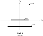
- a linear trajectory is a straight line in Hx and Hy space where Hx represents a horizontal magnetic field and Hy represents a vertical magnetic field.
- TMR elements and GMR elements may be used to construct bridges that have a linear response.
- an output of a bridge that includes TMR elements or GMR elements has a linear response with respect to the horizontal magnetic field.
- an illustrative TMR element 200 can have a stack 202 of layers 206, 210, 214, 218, 222, 226, 228, 232, indicative of one pillar of a multi-pillar TMR element.
- the layer 206 is a seed layer (e.g., a copper nickel (CuN) layer) with the layer 210 located on the seed layer 206.
- the layer 210 includes platinum manganese (PtMn) or iridium manganese (IrMn), for example.
- the layer 214 is located on the layer 210 and the layer 218 is located on the layer 214.
- the layer 214 includes cobalt iron (CoFe) and the layer 218 is a spacer layer and includes ruthenium (Ru).
- a magnesium oxide (MgO) layer 226 is sandwiched between two cobalt iron boron (CoFeB) layers 222, 228.
- a cap layer 232 e.g., tantalum (Ta) is located on the CoFeB layer 228.
- the layer 214 is a single layer pinned layer that is magnetically coupled to the layer 210. The physical mechanism that is coupling layers 210 and 214 together is sometimes called an exchange bias.
- a free layer 230 includes the CoFeB layer 228.
- the free layer 230 may include an additional layer of nickel iron (NiFe) (not shown) and a thin layer of tantalum (not shown) between the CoFeB layer 228 and the NiFe layer.
- NiFe nickel iron
- tantalum tantalum
- a driving current running through the TMR element 200 runs through the layers of the stack, running between seed and cap layers 206 and 232, i.e., perpendicular to a surface of a bottom electrode 204.
- the TMR element 200 can have a maximum response axis that is parallel to the surface of the bottom electrode 204 and that is in a direction 229, and also parallel to the magnetization direction of the reference layer 250, comprised of layers 210, 214, 218, and 222, most notably in the layer CoFeB 222.
- the TMR element 200 has a maximum response axis (maximum response to external fields) aligned with the arrow 229, and parallel to magnetic fields of the reference layer 250, notably pinned layer 222. Also, in general, it is rotations of the magnetic direction of the free layer 230 caused by external magnetic fields that result in changes of resistance of the TMR element 200, which may be due to a change in angle or a change in amplitude if an external bias is present because the sum vector of the external field and the bias is causing a change in the angle between the reference and free layers.
- TMR elements and GMR elements may be used to construct bridges that have linear trajectories; however, these trajectories are not centered about the vertical axis (Hy) or not parallel to the sensor sensitive axis or neither of both.
- a linear trajectory 302 and a linear trajectory 304 are not centered about the vertical axis (Hy axis).
- These linear trajectories may be used to construct bridges that have an output that has a linear response with respect to a horizontal magnetic field (Hx).
- an example of a linear bridge is a bridge 402.
- the bridge 402 is a current-driven bridge.
- the bridge 402 includes a magnetoresistance (MR) element 404a, an MR element 404b, an MR element 406a and an MR element 406b.
- Each MR element 404a, 404b, 406a, 406b includes a reference direction.
- the MR element 404a includes a reference direction 414a
- the MR element 404b includes a reference direction 414b
- the MR element 406a includes a reference direction 416a
- the MR element 406b includes a reference direction 416b.
- a reference direction indicates the direction the MR element is most sensitive to an external magnetic field.
- the MR element 404a and the MR element 404b are a first type of MR element that is the MR elements 404a, 404b are electrically the same and their reference angles 414a, 414b are equal.
- the first type of MR element has a resistance, R type1 .
- the MR element 406a and the MR element 406b are a second type of MR element that is the MR elements 406a, 406b are electrically the same and their reference angles 416a, 416b are equal.
- the second type of MR element has a resistance, R type2 .
- the reference angle 414a, 414b and the reference angle 416a, 416b are determined.
- the output voltage of the bridge is equal to Icc ⁇ (R type1 - R type2 ), where Icc is the current that supplies the bridge 402.
- the MR elements 404a, 404b provide most of the signal from the linear bridge 402 by setting a reference direction the MR elements 406a, 406b of the second type may offset the nonlinearity of the MR elements 404a, 404b of the second type.
- Process 500 measures a magnetic field response for a MR element at different tilting angles (502).
- Process 500 determines, for each resistance combination of first and second types of bridge MR elements, a value (514).
- a resistance combination is a resistance of the first type of MR element less a resistance of the second type of MR element (e.g., a resistance of the MR element 404a less a resistance of the MR element 406a (see FIG. 4 ) or (R type1 - R type2 ).
- Each resistance combination has a value.
- the value is a linear value having a value between zero and a hundred where zero is the most linear value and 100 is the least linear value.
- Process 500 selects a value from the resistance combination values indicating the most linear response (518). For example, a linear value closest to zero is selected.
- Process 500 selects a reference angle for each type of bridge MR element corresponding to the selected value (522).
- the selected value from processing block 518 is associated resistance combination which is associated with a reference angle 414a, 414b for the first type of MR elements 404a, 404b and a reference angle 416a, 416b for the second type of MR elements 406a, 406b.
- a graph 600 depicts various examples of tilted and repeated magnetic field trajectories for an MR element.
- Each different tiled angle is associate with a difference reference angle.
- a tilted magnetic field trajectory is a magnetic field trajectory 606 associated with a first reference angle.
- a tilted magnetic field trajectory is a magnetic field trajectory 608 associated with a second reference angle.
- An example of the pinning direction of the MR element is a pinning direction 602 (similar to the pinning direction on layer 222 ( FIG. 2 ).
- FIG. 6B another example of the graph 600 is a graph 600'.
- the graph 600' depicts more than 200 tilted magnetic field trajectories.
- a 1.5° angle step is used and a 2.5 Oe magnetic field step is used to produce the more than 200 tilted magnetic field trajectories.
- Each magnetic field trajectory represents a different reference angle.
- a magnetic field trajectory 612 is associated with a reference angle of 135° and a magnetic field trajectory 614 is associated with a reference angle of 0°.
- a graph 700 depicts each line (e.g., a line 702, a line 704) represents the resistance of an MR element with reference 602 with respect to linear trajectory 612, for example.
- a graph 800 is identical to graph 300 except the linear trajectories 802, 804 include locations 806, 808, respectively.
- the locations 806, 808 indicate where in the horizontal magnetic field (Hx) it is desired that the linear bridge produces a zero-voltage output.
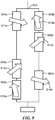
- an example of a linear bridge that has an output that is linear but includes a point where the output voltage is zero is a bridge 902.
- the bridge 902 is similar to the bridge 402 but includes a third type of MR elements. Reference angles for the third type of MR elements are determined to enable that the horizontal magnetic field (Hx) value at the location desired (e.g., either location 806 or the location 808) is a point where the bridge 902 has zero output.
- Hx horizontal magnetic field
- the bridge 902 includes MR element 904a, an MR element 904b, an MR element 906a, an MR element 906b, an MR element 908a and an MR element 908b.
- Each MR element 904a, 904b, 906a, 906b, 908a, 908b includes a reference direction.
- the MR element 904a includes a reference direction 914a
- the MR element 904b includes a reference direction 914b
- the MR element 906a includes a reference direction 916a
- the MR element 906b includes a reference direction 916b
- the MR element 908a includes a reference direction 918a
- the MR element 908b includes a reference direction 918b.
- the MR element 904a and the MR element 904b are the first type of MR element that is the MR elements 904a, 904b are electrically the same and their reference angles 914a, 914b are equal.
- the MR element 906a and the MR element 906b are the second type of MR element that is the MR elements 906a, 906b are electrically the same and their reference angles 916a, 916b are equal.
- the MR element 908a and the MR element 908b are the second type of MR element that is the MR elements 908a, 908b are electrically the same and their reference angles 918a, 918b are equal.
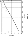
- a graph 1000 includes a curve 1002 which is an example, of a voltage output of a bridge, such as for example, the bridge 902 ( FIG. 9 ).
- the curve 1002 is substantially linear indicating that the bridge output has a linear response with respect to the horizontal magnetic field.
- a process to determine the reference angle of the third type of MR elements is a process 1100.
- Process 1000 determines the resistance that has the least dynamic resistance to average resistance (over the application magnetic field trajectory) ratio (1102). For example, in the graph 700, the resistance that has the least dynamic resistance to average resistance ratio is determined, where the dynamic resistance varies with the applied magnetic field.
- Process 1100 selects a reference angle associated with resistance combination that has the least dynamic resistance to average resistance (over the application magnetic field trajectory) ratio (1106). For example, in the graph 700 the reference angle associated with the resistance that has the least dynamic resistance to average resistance ratio is selected.
- MR 908a, 908b elements instead of adding MR 908a, 908b elements, a combination of different MR elements with different reference directions may be added that would, once connected together in series or in parallel, produce a small dynamic resitance to average resistance ratio.
- an example of a computer is a computer 1200 includes a processor 1202, a volatile memory 1204, a non-volatile memory 1206 (e.g., hard disk) and the user interface (UI) 1208 (e.g., a graphical user interface, a mouse, a keyboard, a display, touch screen and so forth).
- the non-volatile memory 1206 stores computer instructions 1212, an operating system 1216 and data 1218.
- the computer instructions 1212 are executed by the processor 1202 out of volatile memory 1204 to perform all or part of the processes described herein (e.g., processes 500 and 1100).
- the processes described herein are not limited to use with the hardware and software of FIG. 12 ; they may find applicability in any computing or processing environment and with any type of machine or set of machines that is capable of running a computer program.
- the processes described herein may be implemented in hardware, software, or a combination of the two.
- the processes described herein may be implemented in computer programs executed on programmable computers/machines that each includes a processor, a non-transitory machine-readable medium or other article of manufacture that is readable by the processor (including volatile and non-volatile memory and/or storage elements), at least one input device, and one or more output devices.
- Program code may be applied to data entered using an input device to perform any of the processes described herein and to generate output information.
- the system may be implemented, at least in part, via a computer program product, (e.g., in a non-transitory machine-readable storage medium), for execution by, or to control the operation of, data processing apparatus (e.g., a programmable processor, a computer, or multiple computers)).
- data processing apparatus e.g., a programmable processor, a computer, or multiple computers
- Each such program may be implemented in a high-level procedural or object-oriented programming language to communicate with a computer system.
- the programs may be implemented in assembly or machine language.
- the language may be a compiled or an interpreted language and it may be deployed in any form, including as a stand-alone program or as a module, component, subroutine, or other unit suitable for use in a computing environment.
- a computer program may be deployed to be executed on one computer or on multiple computers at one site or distributed across multiple sites and interconnected by a communication network.
- a computer program may be stored on a non-transitory machine-readable medium that is readable by a general or special purpose programmable computer for configuring and operating the computer when the non-transitory machine-readable medium is read by the computer to perform the processes described herein.
- the processes described herein may also be implemented as a non-transitory machine-readable storage medium, configured with a computer program, where upon execution, instructions in the computer program cause the computer to operate in accordance with the processes.
- a non-transitory machine-readable medium may include but is not limited to a hard drive, compact disc, flash memory, non-volatile memory, volatile memory, magnetic diskette and so forth but does not include a transitory signal per se.
- the processes 500 and 1100 are is not limited to the specific processing order of FIGS. 5 and 11 , respectively. Rather, any of the processing blocks of FIGS. 5 and 11 may be re-ordered, combined or removed, performed in parallel or in serial, as necessary, to achieve the results set forth above.
- the processing blocks (for example, the processes 500 and 1100) associated with implementing the system may be performed by one or more programmable processors executing one or more computer programs to perform the functions of the system. All or part of the system may be implemented as, special purpose logic circuitry (e.g., an FPGA (field-programmable gate array) and/or an ASIC (application-specific integrated circuit)). All or part of the system may be implemented using electronic hardware circuitry that include electronic devices such as, for example, at least one of a processor, a memory, programmable logic devices or logic gates.
- special purpose logic circuitry e.g., an FPGA (field-programmable gate array) and/or an ASIC (application-specific integrated circuit)
- All or part of the system may be implemented using electronic hardware circuitry that include electronic devices such as, for example, at least one of a processor, a memory, programmable logic devices or logic gates.
- the linear bridges described herein may be used in a camera.
- the camera may be used in mobile phone.
- the camera 1300 includes a magnetic-field sensor 1304, a focus controller 1324, a lens 1336 and a magnetic target 1336.
- the magnetic-field sensor 1304 includes a bridge 1312.
- the bridge 1312 is similar to the bridge 402. In another example, the bridge 1312 is similar to the bridge 1002.
- the magnetic target 1336 may be moved and detected by the magnetic field sensor 1304 to provide an output to the focus controller 1324 to change the focal length of the lens 1336.
Landscapes
- Physics & Mathematics (AREA)
- General Physics & Mathematics (AREA)
- Condensed Matter Physics & Semiconductors (AREA)
- Measuring Magnetic Variables (AREA)
- Hall/Mr Elements (AREA)
Abstract
Description
- The term "magnetic-field sensing element" is used to describe a variety of electronic elements that can sense a magnetic field. The magnetic-field sensing element can be, but is not limited to, a Hall Effect element, a magnetoresistance element, or a magnetotransistor. As is known, there are different types of Hall Effect elements, for example, a planar Hall element, a vertical Hall element, and a Circular Vertical Hall (CVH) element. As is also known, there are different types of magnetoresistance elements, for example, a semiconductor magnetoresistance element such as Indium Antimonide (InSb), a giant magnetoresistance (GMR) element, an anisotropic magnetoresistance element (AMR), a tunneling magnetoresistance (TMR) element, and a magnetic tunnel junction (MTJ). The magnetic field sensing element may be a single element or, alternatively, may include two or more magnetic field sensing elements arranged in various configurations, e.g., a half bridge or full (Wheatstone) bridge. Depending on the device type and other application requirements, the magnetic field sensing element may be a device made of a type IV semiconductor material such as Silicon (Si) or Germanium (Ge), or a type III-V semiconductor material like Gallium-Arsenide (GaAs) or an Indium compound, e.g., Indium-Antimonide (InSb).
- As is known, some of the above-described magnetic-field sensing elements tend to have an axis of maximum sensitivity parallel to a substrate that supports the magnetic-field sensing element, and others of the above-described magnetic-field sensing elements tend to have an axis of maximum sensitivity perpendicular to a substrate that supports the magnetic-field sensing element. In particular, planar Hall elements tend to have axes of sensitivity perpendicular to a substrate, while metal based or metallic magnetoresistance elements (e.g., GMR, TMR, AMR) and vertical Hall elements tend to have axes of sensitivity parallel to a substrate.
- In one aspect, a bridge includes a first magnetoresistance element having a first reference angle, a second magnetoresistance element in series with the first magnetoresistance element and having a second reference angle, a third magnetoresistance element in parallel with the first magnetoresistance element and having the first reference angle and a fourth magnetoresistance element in series with the third magnetoresistance element and having the second reference angle. An output of the bridge has a linear response over a range of horizontal magnetic field values not centered about a zero value and a reference angle indicates an angle the magnetoresistance element is most sensitive to changes in a magnetic field.
- In another aspect, a method of forming a bridge that includes a first type of magnetoresistance elements and a second type of magnetoresistance elements. The method includes measuring a magnetic field response for a magnetoresistance element at different tilt angles; for each tilt angle, measuring a resistance of the magnetoresistance element; using the measured resistance for each tilt angle, determining a value for each resistance combination of the first type and the second type of magnetoresistance elements; selecting the value indicating an output of the bridge has a linear response over a range of horizontal magnetic field values not centered about a zero value; selecting a first reference angle for the first type of magnetoresistance elements corresponding to the selected value; and selecting a second reference angle for the second type of magnetoresistance elements corresponding to the selected value. The first reference angle indicates an angle the first type of magnetoresistance elements is most sensitive to changes in a magnetic field.
- In a further aspect, a camera includes a magnetic field sensor comprising a bridge. The bridge includes a first magnetoresistance element having a first reference angle, a second magnetoresistance element in series with the first magnetoresistance element and having a second reference angle, a third magnetoresistance element in parallel with the first magnetoresistance element and having the first reference angle and a fourth magnetoresistance element in series with the third magnetoresistance element and having the second reference angle. An output of the bridge has a linear response over a range of horizontal magnetic field values not centered about a zero value, and a reference angle indicates an angle the magnetoresistance element is most sensitive to changes in a magnetic field.
- One or more of the aspects above can have one or more of the following features. The range of horizontal magnetic field values can include horizontal magnetic field values none of which have zero values. The first, second, third and fourth magnetoresistance elements can each be a giant magnetoresistance (GMR) element or a tunnel magnetoresistance (TMR) element. The bridge can include a fifth magnetoresistance element in series with the first magnetoresistance element and having a third reference angle; and a sixth magnetoresistance element in series with the third magnetoresistance element and having the third reference angle. The range of horizontal magnetic field values not centered about a zero value can include a non-zero value corresponding to the output of the bridge having a zero value. The fifth magnetoresistance element and the sixth magnetoresistance element can be constructed to be the same. The range of horizontal magnetic field values can be associated with vertical magnetic field values none of which are 0 Oersted (Oe). The first reference angle and the second reference angle can enable the output of the bridge to have the linear response over the range of horizontal magnetic field values not centered about the zero value. The first reference angle and the second reference angle can enable the output of the bridge to have the linear response over the range of horizontal magnetic field values none of which have zero values. The first magnetoresistance element and the third magnetoresistance element can be constructed to be the same. The second magnetoresistance element and the fourth magnetoresistance element can be constructed to be the same.
- The foregoing features may be more fully understood from the following description of the drawings. The drawings aid in explaining and understanding the disclosed technology. Since it is often impractical or impossible to illustrate and describe every possible embodiment, the provided figures depict one or more illustrative embodiments. Accordingly, the figures are not intended to limit the scope of the broad concepts, systems and techniques described herein. Like numbers in the figures denote like elements.
-
FIG. 1 is a graph of an example of magnetic field trajectories for a linear magnetic field sensor; -
FIG. 2 is a block diagram of a prior art example of a tunneling magnetoresistance (TMR) element; -
FIG. 3 is a graph of an example of magnetic field linear trajectories for a bridge that includes magnetoresistance (MR) elements; -
FIG. 4 is a circuit diagram of an example of the bridge that includes MR elements; -
FIG. 5 is a flow diagram of an example of a process to determine reference angles for the MR elements; -
FIG. 6A is a graph of an example of magnetic field trajectories; -
FIG. 6B is a graph of another example of magnetic field trajectories; -
FIG. 7 is a graph of an example of resistance of an MR element with respect to magnetic field trajectories; -
FIG.8 is a graph of an example of magnetic field trajectories with zero offsets for a bridge that includes MR elements; -
FIG. 9 is a circuit diagram of an example of the bridge that includes MR elements used to generate linear response having a zero voltage; -
FIG. 10 is a graph of an example of an output of the bridge inFIG. 9 ; -
FIG. 11 is a flow diagram of an example of a process to a reference angle for a third type of MR elements in the bridge ofFIG. 9 ; -
FIG. 12 is a block diagram of an example of a computer on which any of the process ofFIG. 5 and/orFIG. 11 may be implemented; and -
FIG. 13 is block diagram of an example of camera that includes a bridge that includes MR elements. - Described herein are techniques to fabricate bridges for linear magnetometers (linear bridges) using nonlinear magnetoresistance elements, such as, for example, a giant magnetoresistance (GMR) elements or a tunneling magnetoresistance (TMR) elements. In some examples, the techniques described herein may be used to construct linear magnetometers that are linear in magnetic field trajectories and ranges where magnetoresistance elements are typically not linear.
- Referring to
FIG. 1 , a linear trajectory is a straight line in Hx and Hy space where Hx represents a horizontal magnetic field and Hy represents a vertical magnetic field. Agraph 100 includes examples of linear trajectories from linear magnetic field sensors that are centered about Hx = 0 Oersted (Oe). In one example, alinear trajectory 102 is centered about Hx = 0 Oe and has a Hy = 0 Oe. In another example, alinear trajectory 104 is centered about Hx = 0 Oe and has a Hy = a fixed nonzero value. - As will be further described herein, TMR elements and GMR elements may be used to construct bridges that have a linear response. For example, using the techniques described herein, an output of a bridge that includes TMR elements or GMR elements has a linear response with respect to the horizontal magnetic field.
- Referring to
FIG. 2 , anillustrative TMR element 200 can have astack 202 oflayers layer 206 is a seed layer (e.g., a copper nickel (CuN) layer) with thelayer 210 located on theseed layer 206. Thelayer 210 includes platinum manganese (PtMn) or iridium manganese (IrMn), for example. Thelayer 214 is located on thelayer 210 and thelayer 218 is located on thelayer 214. In one example, thelayer 214 includes cobalt iron (CoFe) and thelayer 218 is a spacer layer and includes ruthenium (Ru). On thelayer 218, a magnesium oxide (MgO)layer 226 is sandwiched between two cobalt iron boron (CoFeB) layers 222, 228. A cap layer 232 (e.g., tantalum (Ta)) is located on theCoFeB layer 228. Thelayer 214 is a single layer pinned layer that is magnetically coupled to thelayer 210. The physical mechanism that is couplinglayers - A
free layer 230 includes theCoFeB layer 228. In some examples, thefree layer 230 may include an additional layer of nickel iron (NiFe) (not shown) and a thin layer of tantalum (not shown) between theCoFeB layer 228 and the NiFe layer. - It will be understood that a driving current running through the
TMR element 200 runs through the layers of the stack, running between seed andcap layers bottom electrode 204. TheTMR element 200 can have a maximum response axis that is parallel to the surface of thebottom electrode 204 and that is in adirection 229, and also parallel to the magnetization direction of thereference layer 250, comprised oflayers layer CoFeB 222. - The
TMR element 200 has a maximum response axis (maximum response to external fields) aligned with thearrow 229, and parallel to magnetic fields of thereference layer 250, notably pinnedlayer 222. Also, in general, it is rotations of the magnetic direction of thefree layer 230 caused by external magnetic fields that result in changes of resistance of theTMR element 200, which may be due to a change in angle or a change in amplitude if an external bias is present because the sum vector of the external field and the bias is causing a change in the angle between the reference and free layers. - Referring to
FIG. 3 , TMR elements and GMR elements may be used to construct bridges that have linear trajectories; however, these trajectories are not centered about the vertical axis (Hy) or not parallel to the sensor sensitive axis or neither of both. For example, alinear trajectory 302 and alinear trajectory 304 are not centered about the vertical axis (Hy axis). These linear trajectories may be used to construct bridges that have an output that has a linear response with respect to a horizontal magnetic field (Hx). - Referring to
FIG. 4 , an example of a linear bridge is abridge 402. In one example, thebridge 402 is a current-driven bridge. - The
bridge 402 includes a magnetoresistance (MR)element 404a, anMR element 404b, anMR element 406a and anMR element 406b. EachMR element MR element 404a includes areference direction 414a, theMR element 404b includes areference direction 414b, theMR element 406a includes areference direction 416a and theMR element 406b includes areference direction 416b. As used herein, a reference direction indicates the direction the MR element is most sensitive to an external magnetic field. - The
MR element 404a and theMR element 404b are a first type of MR element that is theMR elements reference angles - The
MR element 406a and theMR element 406b are a second type of MR element that is theMR elements reference angles - As will be further described herein, in order to achieve a bridge that has an output that has a linear response, the
reference angle reference angle linear bridge 402 is a current driven bridge, the output voltage of the bridge is equal to Icc ∗ (Rtype1 - Rtype2), where Icc is the current that supplies thebridge 402. - In one example, with the
reference angle reference angle MR elements linear bridge 402 by setting a reference direction theMR elements MR elements - Referring to
FIG. 5 , an example of a process to determine reference angles is aprocess 500. Process 500 measures a magnetic field response for a MR element at different tilting angles (502). -
Process 500 determines, for each resistance combination of first and second types of bridge MR elements, a value (514). For example, a resistance combination is a resistance of the first type of MR element less a resistance of the second type of MR element (e.g., a resistance of theMR element 404a less a resistance of theMR element 406a (seeFIG. 4 ) or (Rtype1 - Rtype2). Each resistance combination has a value. In one example, the value is a linear value having a value between zero and a hundred where zero is the most linear value and 100 is the least linear value. -
Process 500 selects a value from the resistance combination values indicating the most linear response (518). For example, a linear value closest to zero is selected. -
Process 500 selects a reference angle for each type of bridge MR element corresponding to the selected value (522). For example, the selected value from processingblock 518 is associated resistance combination which is associated with areference angle MR elements reference angle MR elements - Referring to
FIG. 6A , agraph 600 depicts various examples of tilted and repeated magnetic field trajectories for an MR element. Each different tiled angle is associate with a difference reference angle. For example, a tilted magnetic field trajectory is amagnetic field trajectory 606 associated with a first reference angle. In another example, a tilted magnetic field trajectory is amagnetic field trajectory 608 associated with a second reference angle. An example of the pinning direction of the MR element is a pinning direction 602 (similar to the pinning direction on layer 222 (FIG. 2 ). - Referring to
FIG. 6B , another example of thegraph 600 is a graph 600'. The graph 600' depicts more than 200 tilted magnetic field trajectories. In the graph 600', a 1.5° angle step is used and a 2.5 Oe magnetic field step is used to produce the more than 200 tilted magnetic field trajectories. Each magnetic field trajectory represents a different reference angle. For example, amagnetic field trajectory 612 is associated with a reference angle of 135° and amagnetic field trajectory 614 is associated with a reference angle of 0°. - Referring to
FIG. 7 , agraph 700 depicts each line (e.g., aline 702, a line 704) represents the resistance of an MR element withreference 602 with respect tolinear trajectory 612, for example. - Referring to
FIG. 8 , agraph 800 is identical to graph 300 except thelinear trajectories locations locations - Referring to
FIG. 9 , an example of a linear bridge that has an output that is linear but includes a point where the output voltage is zero is abridge 902. Thebridge 902 is similar to thebridge 402 but includes a third type of MR elements. Reference angles for the third type of MR elements are determined to enable that the horizontal magnetic field (Hx) value at the location desired (e.g., eitherlocation 806 or the location 808) is a point where thebridge 902 has zero output. - The
bridge 902 includesMR element 904a, anMR element 904b, anMR element 906a, anMR element 906b, anMR element 908a and anMR element 908b. EachMR element MR element 904a includes areference direction 914a, theMR element 904b includes areference direction 914b, theMR element 906a includes areference direction 916a, theMR element 906b includes areference direction 916b, theMR element 908a includes areference direction 918a and theMR element 908b includes areference direction 918b. - The
MR element 904a and theMR element 904b are the first type of MR element that is theMR elements reference angles - The
MR element 906a and theMR element 906b are the second type of MR element that is theMR elements reference angles - The
MR element 908a and theMR element 908b are the second type of MR element that is theMR elements reference angles - Referring to
FIG. 10 , agraph 1000 includes acurve 1002 which is an example, of a voltage output of a bridge, such as for example, the bridge 902 (FIG. 9 ). Thecurve 1002 is substantially linear indicating that the bridge output has a linear response with respect to the horizontal magnetic field. - Referring to
FIG. 11 , a process to determine the reference angle of the third type of MR elements is aprocess 1100.Process 1000 determines the resistance that has the least dynamic resistance to average resistance (over the application magnetic field trajectory) ratio (1102). For example, in thegraph 700, the resistance that has the least dynamic resistance to average resistance ratio is determined, where the dynamic resistance varies with the applied magnetic field. -
Process 1100 selects a reference angle associated with resistance combination that has the least dynamic resistance to average resistance (over the application magnetic field trajectory) ratio (1106). For example, in thegraph 700 the reference angle associated with the resistance that has the least dynamic resistance to average resistance ratio is selected. - In other examples, instead of adding
MR - Referring to
FIG. 12 , an example of a computer is acomputer 1200 includes aprocessor 1202, avolatile memory 1204, a non-volatile memory 1206 (e.g., hard disk) and the user interface (UI) 1208 (e.g., a graphical user interface, a mouse, a keyboard, a display, touch screen and so forth). Thenon-volatile memory 1206stores computer instructions 1212, anoperating system 1216 anddata 1218. In one example, thecomputer instructions 1212 are executed by theprocessor 1202 out ofvolatile memory 1204 to perform all or part of the processes described herein (e.g., processes 500 and 1100). - The processes described herein (e.g., processes 500 and 1100) are not limited to use with the hardware and software of
FIG. 12 ; they may find applicability in any computing or processing environment and with any type of machine or set of machines that is capable of running a computer program. The processes described herein may be implemented in hardware, software, or a combination of the two. The processes described herein may be implemented in computer programs executed on programmable computers/machines that each includes a processor, a non-transitory machine-readable medium or other article of manufacture that is readable by the processor (including volatile and non-volatile memory and/or storage elements), at least one input device, and one or more output devices. Program code may be applied to data entered using an input device to perform any of the processes described herein and to generate output information. - The system may be implemented, at least in part, via a computer program product, (e.g., in a non-transitory machine-readable storage medium), for execution by, or to control the operation of, data processing apparatus (e.g., a programmable processor, a computer, or multiple computers)). Each such program may be implemented in a high-level procedural or object-oriented programming language to communicate with a computer system. However, the programs may be implemented in assembly or machine language. The language may be a compiled or an interpreted language and it may be deployed in any form, including as a stand-alone program or as a module, component, subroutine, or other unit suitable for use in a computing environment. A computer program may be deployed to be executed on one computer or on multiple computers at one site or distributed across multiple sites and interconnected by a communication network. A computer program may be stored on a non-transitory machine-readable medium that is readable by a general or special purpose programmable computer for configuring and operating the computer when the non-transitory machine-readable medium is read by the computer to perform the processes described herein. For example, the processes described herein may also be implemented as a non-transitory machine-readable storage medium, configured with a computer program, where upon execution, instructions in the computer program cause the computer to operate in accordance with the processes. A non-transitory machine-readable medium may include but is not limited to a hard drive, compact disc, flash memory, non-volatile memory, volatile memory, magnetic diskette and so forth but does not include a transitory signal per se.
- The processes described herein are not limited to the specific examples described. For example, the
processes FIGS. 5 and11 , respectively. Rather, any of the processing blocks ofFIGS. 5 and11 may be re-ordered, combined or removed, performed in parallel or in serial, as necessary, to achieve the results set forth above. - The processing blocks (for example, the
processes 500 and 1100) associated with implementing the system may be performed by one or more programmable processors executing one or more computer programs to perform the functions of the system. All or part of the system may be implemented as, special purpose logic circuitry (e.g., an FPGA (field-programmable gate array) and/or an ASIC (application-specific integrated circuit)). All or part of the system may be implemented using electronic hardware circuitry that include electronic devices such as, for example, at least one of a processor, a memory, programmable logic devices or logic gates. - Referring to
FIG. 13 , the linear bridges described herein (e.g., thebridge 402, the bridge 1002) may be used in a camera. In one example, the camera may be used in mobile phone. Thecamera 1300 includes a magnetic-field sensor 1304, afocus controller 1324, alens 1336 and amagnetic target 1336. - The magnetic-
field sensor 1304 includes abridge 1312. In one example, thebridge 1312 is similar to thebridge 402. In another example, thebridge 1312 is similar to thebridge 1002. - In one example, the
magnetic target 1336 may be moved and detected by themagnetic field sensor 1304 to provide an output to thefocus controller 1324 to change the focal length of thelens 1336. - Elements of different embodiments described herein may be combined to form other embodiments not specifically set forth above. Various elements, which are described in the context of a single embodiment, may also be provided separately or in any suitable subcombination. Other embodiments not specifically described herein are also within the scope of the following claims.
Claims (22)
- A bridge comprising:a first magnetoresistance element having a first reference angle;a second magnetoresistance element in series with the first magnetoresistance element and having a second reference angle;a third magnetoresistance element in parallel with the first magnetoresistance element and having the first reference angle; anda fourth magnetoresistance element in series with the third magnetoresistance element and having the second reference angle,wherein an output of the bridge has a linear response over a range of horizontal magnetic field values not centered about a zero value,wherein a reference angle indicates an angle the magnetoresistance element is most sensitive to changes in a magnetic field.
- The bridge of claim 1, wherein the range of horizontal magnetic field values comprises horizontal magnetic field values none of which have zero values.
- The bridge of claim 1, wherein the first, second, third and fourth magnetoresistance elements are each a giant magnetoresistance (GMR) element or a tunnel magnetoresistance (TMR) element.
- The bridge of claim 1, further comprising:a fifth magnetoresistance element in series with the first magnetoresistance element and having a third reference angle; anda sixth magnetoresistance element in series with the third magnetoresistance element and having the third reference angle,wherein the range of horizontal magnetic field values not centered about a zero value comprises a non-zero value corresponding to the output of the bridge having a zero value.
- The bridge of claim 4, wherein the fifth magnetoresistance element and the sixth magnetoresistance element are constructed to be the same.
- The bridge of claim 1, wherein the range of horizontal magnetic field values are associated with vertical magnetic field values none of which are 0 Oersted (Oe).
- The bridge of claim 1, wherein the first reference angle and the second reference angle enable the output of the bridge to have the linear response over the range of horizontal magnetic field values not centered about the zero value.
- The bridge of claim 7, wherein the first reference angle and the second reference angle enable the output of the bridge to have the linear response over the range of horizontal magnetic field values none of which have zero values.
- The bridge of claim 1, wherein the first magnetoresistance element and the third magnetoresistance element are constructed to be the same.
- The bridge of claim 9, wherein the second magnetoresistance element and the fourth magnetoresistance element are constructed to be the same.
- A method of forming a bridge comprising a first type of magnetoresistance elements and a second type of magnetoresistance elements, comprising:measuring a magnetic field response for a magnetoresistance element at different tilt angles;for each tilt angle, measuring a resistance of the magnetoresistance element;using the measured resistance for each tilt angle, determining a value for each resistance combination of the first type and the second type of magnetoresistance elements;selecting the value indicating an output of the bridge has a linear response over a range of horizontal magnetic field values not centered about a zero value;selecting a first reference angle for the first type of magnetoresistance elements corresponding to the selected value, wherein the first reference angle indicates an angle the first type of magnetoresistance elements is most sensitive to changes in a magnetic field; andselecting a second reference angle for the second type of magnetoresistance elements corresponding to the selected value.
- The method of claim 11, wherein the second reference angle compensates for non-linearity.
- The method of claim 11, wherein selecting the value indicating the output of the bridge has a linear response over a range of horizontal magnetic field values not centered about a zero value comprises selecting the value indicating the output of the bridge has a linear response over the range of horizontal magnetic field values comprising only non-zero values.
- The method of claim 11, wherein measuring the magnetic field response for the magnetoresistance element at different tilt angles comprises measuring a magnetic field response for a magnetoresistance element comprising a giant magnetoresistance (GMR) element or a tunnel magnetoresistance (TMR) element.
- The method of claim 11, further comprising:determining, for each tilt angle, the resistance combination that has the lowest change in resistance; andselecting a third reference angle for a third type of magnetoresistance elements of the bridge corresponding to the lowest change in resistance,wherein the third reference angle enables the range of horizontal magnetic field values not centered about a zero value to comprise a non-zero value corresponding to the output of the bridge having a zero value.
- The method of claim 11, wherein selecting the value indicating the output of the bridge has a linear response over a range of horizontal magnetic field values not centered about a zero value comprises selecting the value indicating the output of the bridge has a linear response over the range of horizontal magnetic field values associated with vertical magnetic field values none of which are 0 Oersted (Oe).
- The method of claim 11, wherein the first reference angle and the second reference angle enable the output of the bridge to have the linear response over the range of horizontal magnetic field values not centered about the zero value.
- The method of claim 17, wherein the first reference angle and the second reference angle enable the linear response to have the range of horizontal magnetic field values none of which have zero values.
- The method of claim 11, further comprising:connecting a first magnetoresistance element in series with a second magnetoresistance element; andconnecting a third magnetoresistance element in series with a fourth magnetoresistance element and in parallel with the first and second magnetoresistance elements.
- A camera, comprising:
a magnetic field sensor comprising a bridge, the bridge comprising:a first magnetoresistance element having a first reference angle;a second magnetoresistance element in series with the first magnetoresistance element and having a second reference angle;a third magnetoresistance element in parallel with the first magnetoresistance element and having the first reference angle; anda fourth magnetoresistance element in series with the third magnetoresistance element and having the second reference angle,wherein an output of the bridge has a linear response over a range of horizontal magnetic field values not centered about a zero value,wherein a reference angle indicates an angle the magnetoresistance element is most sensitive to changes in a magnetic field. - The camera of claim 20 wherein the camera is disposed in a cellular device.
- The camera of claim 1, further comprising:a magnetic target;a focus controller;a lens;wherein a movement of the magnetic target is detected by the magnetic field sensor to provide an output to the focus controller to change the focal length of the lens.
Applications Claiming Priority (1)
| Application Number | Priority Date | Filing Date | Title |
|---|---|---|---|
| US16/822,488 US11467233B2 (en) | 2020-03-18 | 2020-03-18 | Linear bridges having nonlinear elements |
Publications (2)
| Publication Number | Publication Date |
|---|---|
| EP3882647A1 true EP3882647A1 (en) | 2021-09-22 |
| EP3882647B1 EP3882647B1 (en) | 2024-02-14 |
Family
ID=74586951
Family Applications (1)
| Application Number | Title | Priority Date | Filing Date |
|---|---|---|---|
| EP21156380.4A Active EP3882647B1 (en) | 2020-03-18 | 2021-02-10 | Linear bridges having nonlinear elements |
Country Status (2)
| Country | Link |
|---|---|
| US (1) | US11467233B2 (en) |
| EP (1) | EP3882647B1 (en) |
Families Citing this family (7)
| Publication number | Priority date | Publication date | Assignee | Title |
|---|---|---|---|---|
| CN115803647A (en) * | 2020-07-06 | 2023-03-14 | 阿莱戈微系统有限责任公司 | Linear bridge with non-linear elements for operation at high magnetic field strengths |
| US11630168B2 (en) * | 2021-02-03 | 2023-04-18 | Allegro Microsystems, Llc | Linear sensor with dual spin valve element having reference layers with magnetization directions different from an external magnetic field direction |
| US12442874B2 (en) | 2021-11-04 | 2025-10-14 | Allegro Microsystems, Llc | Angle sensor with a single die using a single target |
| US11719527B2 (en) | 2021-11-04 | 2023-08-08 | Allegro Microsystems, Llc | Angle sensor with a single die using a single target |
| US12517195B2 (en) | 2023-12-04 | 2026-01-06 | Allegro Microsystems, Llc | Low residual offset sensor |
| US12613293B2 (en) | 2023-12-04 | 2026-04-28 | Allegro Microsystems, Llc | Sensor with common mode rejection and offset correction |
| US12546836B2 (en) | 2024-03-15 | 2026-02-10 | Allegro Microsystems, Llc | TMR vortex layout for back bias sensors |
Citations (6)
| Publication number | Priority date | Publication date | Assignee | Title |
|---|---|---|---|---|
| US20140028307A1 (en) * | 2012-07-26 | 2014-01-30 | Udo Ausserlechner | Magnetoresistive sensor systems and methods having a yaw angle between premagnetization and magnetic field directions |
| US20140225605A1 (en) * | 2011-08-30 | 2014-08-14 | Multidimension Technology Co., Ltd | Mtj three-axis magnetic field sensor and encapsulation method thereof |
| US20180335484A1 (en) * | 2017-05-19 | 2018-11-22 | Allegro Microsystems, Llc | Magnetoresistance element with increased operational range |
| US20190383646A1 (en) * | 2018-01-31 | 2019-12-19 | Allegro Microsystems, Llc | Reducing angle error in a magnetic field angle sensor |
| US10557725B2 (en) * | 2014-11-24 | 2020-02-11 | Sensitec Gmbh | Magnetoresistive wheatstone measuring bridge and angle sensor having at least two such measuring bridges |
| WO2021040797A1 (en) * | 2019-08-27 | 2021-03-04 | Western Digital Technologies, Inc. | Magnetic sensor with serial resistor for asymmetric sensing field range |
Family Cites Families (60)
| Publication number | Priority date | Publication date | Assignee | Title |
|---|---|---|---|---|
| US6730949B2 (en) | 2001-03-22 | 2004-05-04 | Kabushiki Kaisha Toshiba | Magnetoresistance effect device |
| DE10254552A1 (en) | 2002-11-21 | 2004-06-03 | Siemens Ag | An angular position sensor |
| US7570461B2 (en) | 2005-02-28 | 2009-08-04 | Seagate Technology Llc | Magnetic sensor with in-stack biasing |
| US8084969B2 (en) | 2007-10-01 | 2011-12-27 | Allegro Microsystems, Inc. | Hall-effect based linear motor controller |
| WO2009068695A1 (en) | 2007-11-30 | 2009-06-04 | Continental Teves Ag & Co. Ohg | Absolute measurement steering angle sensor arrangement |
| FR2925672B1 (en) | 2007-12-19 | 2010-01-08 | Siemens Vdo Automotive | ANGULAR POSITION MEASURING DEVICE |
| US9823090B2 (en) | 2014-10-31 | 2017-11-21 | Allegro Microsystems, Llc | Magnetic field sensor for sensing a movement of a target object |
| JP5170679B2 (en) | 2008-01-29 | 2013-03-27 | 日立金属株式会社 | Magnetic sensor and rotation angle detection device |
| US7936144B2 (en) | 2008-03-06 | 2011-05-03 | Allegro Microsystems, Inc. | Self-calibration algorithms in a small motor driver IC with an integrated position sensor |
| US9040178B2 (en) | 2008-09-22 | 2015-05-26 | Headway Technologies, Inc. | TMR device with novel free layer structure |
| US8138708B2 (en) | 2008-11-26 | 2012-03-20 | Allegro Microsystems, Inc. | Closed-loop motor driver compensation |
| WO2010098472A1 (en) | 2009-02-26 | 2010-09-02 | 日立金属株式会社 | Angle detector and position detector |
| US8093886B2 (en) | 2009-03-30 | 2012-01-10 | Hitachi Metals, Ltd. | Rotation-angle-detecting apparatus |
| US8461782B2 (en) | 2009-08-27 | 2013-06-11 | Allegro Microsystems, Llc | Linear or rotational motor driver identification |
| EP2330432B1 (en) | 2009-11-19 | 2013-01-09 | Nxp B.V. | Magnetic field sensor |
| JP5177197B2 (en) | 2010-10-13 | 2013-04-03 | Tdk株式会社 | Rotating magnetic field sensor |
| JP5131339B2 (en) | 2010-11-17 | 2013-01-30 | Tdk株式会社 | Rotating magnetic field sensor |
| JP5062454B2 (en) | 2011-05-24 | 2012-10-31 | Tdk株式会社 | Magnetic sensor |
| US8829901B2 (en) | 2011-11-04 | 2014-09-09 | Honeywell International Inc. | Method of using a magnetoresistive sensor in second harmonic detection mode for sensing weak magnetic fields |
| JP2013257231A (en) | 2012-06-13 | 2013-12-26 | Jtekt Corp | Rotation angle sensor |
| JP6074988B2 (en) | 2012-09-28 | 2017-02-08 | アイシン精機株式会社 | Rotation magnetism detection circuit and rotation magnetic sensor |
| US8873944B2 (en) | 2012-10-09 | 2014-10-28 | Allegro Microsystems, Llc | Methods and apparatus for positioning a coil motor |
| US8736316B2 (en) | 2012-10-12 | 2014-05-27 | Allegro Microsystems, Llc | Current driver with output current clamping |
| US9625535B2 (en) | 2013-08-07 | 2017-04-18 | Allegro Microsystems, Llc | Systems and methods for computing a position of a magnetic target |
| US9042716B2 (en) | 2013-08-15 | 2015-05-26 | Allegro Microsystems, Llc | Method and apparatus for determining linear position using multiple magnetic field sensors |
| US20160169707A1 (en) | 2013-08-27 | 2016-06-16 | Tdk Corporation | Rotating field sensor |
| JP6308784B2 (en) | 2014-01-08 | 2018-04-11 | アルプス電気株式会社 | Magnetic sensor |
| US9529060B2 (en) | 2014-01-09 | 2016-12-27 | Allegro Microsystems, Llc | Magnetoresistance element with improved response to magnetic fields |
| US9354284B2 (en) | 2014-05-07 | 2016-05-31 | Allegro Microsystems, Llc | Magnetic field sensor configured to measure a magnetic field in a closed loop manner |
| US9720054B2 (en) | 2014-10-31 | 2017-08-01 | Allegro Microsystems, Llc | Magnetic field sensor and electronic circuit that pass amplifier current through a magnetoresistance element |
| US9823092B2 (en) | 2014-10-31 | 2017-11-21 | Allegro Microsystems, Llc | Magnetic field sensor providing a movement detector |
| US9719806B2 (en) | 2014-10-31 | 2017-08-01 | Allegro Microsystems, Llc | Magnetic field sensor for sensing a movement of a ferromagnetic target object |
| US9322887B1 (en) | 2014-12-01 | 2016-04-26 | Allegro Microsystems, Llc | Magnetic field sensor with magnetoresistance elements and conductive-trace magnetic source |
| JP6191838B2 (en) | 2015-03-09 | 2017-09-06 | Tdk株式会社 | Magnetic sensor |
| CN104900801A (en) * | 2015-04-23 | 2015-09-09 | 美新半导体(无锡)有限公司 | Anti-ferromagnetic pinning AMR (Anisotropic Magneto Resistance) sensor |
| EP3300534B1 (en) | 2015-06-05 | 2020-11-11 | Allegro MicroSystems, LLC | Spin valve magnetoresistance element with improved response to magnetic fields |
| US9605975B2 (en) | 2015-06-05 | 2017-03-28 | Allegro Micorsystems, Llc | Magnetic field sensor for orientation independent speed and direction measurement |
| US9470765B1 (en) | 2015-08-07 | 2016-10-18 | Allegro Microsystems, Llc | Magnetic sensor having enhanced linearization by applied field angle rotation |
| DE102015218855A1 (en) | 2015-09-30 | 2017-03-30 | Siemens Aktiengesellschaft | Signal transmitter with improved detection of the angle signal |
| US10114085B2 (en) | 2016-03-04 | 2018-10-30 | Allegro Microsystems, Llc | Magnetic field sensor with improved response immunity |
| US9910087B2 (en) | 2016-03-14 | 2018-03-06 | Allegro Microsystems, Llc | Integrated circuit and method for detecting a stress condition in the integrated circuit |
| US10041810B2 (en) | 2016-06-08 | 2018-08-07 | Allegro Microsystems, Llc | Arrangements for magnetic field sensors that act as movement detectors |
| US9880026B1 (en) | 2016-07-14 | 2018-01-30 | Allegro Microsystems, Llc | Magnetic field sensor for detecting motion of an object |
| US10036785B2 (en) | 2016-07-18 | 2018-07-31 | Allegro Microsystems, Llc | Temperature-compensated magneto-resistive sensor |
| US10290608B2 (en) | 2016-09-13 | 2019-05-14 | Allegro Microsystems, Llc | Signal isolator having bidirectional diagnostic signal exchange |
| US11022661B2 (en) | 2017-05-19 | 2021-06-01 | Allegro Microsystems, Llc | Magnetoresistance element with increased operational range |
| US10310028B2 (en) | 2017-05-26 | 2019-06-04 | Allegro Microsystems, Llc | Coil actuated pressure sensor |
| US10605626B2 (en) | 2017-06-12 | 2020-03-31 | Infineon Technologies Ag | Angle sensor bridges including star-connected magnetoresistive elements |
| US10557873B2 (en) | 2017-07-19 | 2020-02-11 | Allegro Microsystems, Llc | Systems and methods for closed loop current sensing |
| US10578684B2 (en) | 2018-01-12 | 2020-03-03 | Allegro Microsystems, Llc | Magnetic field sensor having magnetoresistance elements with opposite bias directions |
| US10509058B2 (en) | 2018-01-12 | 2019-12-17 | Allegro Microsystems, Llc | Current sensor using modulation of or change of sensitivity of magnetoresistance elements |
| US10557726B2 (en) | 2018-01-31 | 2020-02-11 | Allegro Microsystems, Llc | Systems and methods for reducing angle error for magnetic field angle sensors |
| US11193989B2 (en) | 2018-07-27 | 2021-12-07 | Allegro Microsystems, Llc | Magnetoresistance assembly having a TMR element disposed over or under a GMR element |
| US10921391B2 (en) | 2018-08-06 | 2021-02-16 | Allegro Microsystems, Llc | Magnetic field sensor with spacer |
| US10605874B2 (en) | 2018-08-06 | 2020-03-31 | Allegro Microsystems, Llc | Magnetic field sensor with magnetoresistance elements having varying sensitivity |
| US11255700B2 (en) | 2018-08-06 | 2022-02-22 | Allegro Microsystems, Llc | Magnetic field sensor |
| US10734443B2 (en) * | 2018-08-27 | 2020-08-04 | Allegro Microsystems, Llc | Dual manetoresistance element with two directions of response to external magnetic fields |
| US10753989B2 (en) | 2018-08-27 | 2020-08-25 | Allegro Microsystems, Llc | Magnetoresistance element with perpendicular or parallel magnetic anistropy |
| TWI747285B (en) * | 2019-05-27 | 2021-11-21 | 愛盛科技股份有限公司 | Magnetic field sensing apparatus |
| US11175359B2 (en) * | 2019-08-28 | 2021-11-16 | Allegro Microsystems, Llc | Reducing voltage non-linearity in a bridge having tunneling magnetoresistance (TMR) elements |
-
2020
- 2020-03-18 US US16/822,488 patent/US11467233B2/en active Active
-
2021
- 2021-02-10 EP EP21156380.4A patent/EP3882647B1/en active Active
Patent Citations (6)
| Publication number | Priority date | Publication date | Assignee | Title |
|---|---|---|---|---|
| US20140225605A1 (en) * | 2011-08-30 | 2014-08-14 | Multidimension Technology Co., Ltd | Mtj three-axis magnetic field sensor and encapsulation method thereof |
| US20140028307A1 (en) * | 2012-07-26 | 2014-01-30 | Udo Ausserlechner | Magnetoresistive sensor systems and methods having a yaw angle between premagnetization and magnetic field directions |
| US10557725B2 (en) * | 2014-11-24 | 2020-02-11 | Sensitec Gmbh | Magnetoresistive wheatstone measuring bridge and angle sensor having at least two such measuring bridges |
| US20180335484A1 (en) * | 2017-05-19 | 2018-11-22 | Allegro Microsystems, Llc | Magnetoresistance element with increased operational range |
| US20190383646A1 (en) * | 2018-01-31 | 2019-12-19 | Allegro Microsystems, Llc | Reducing angle error in a magnetic field angle sensor |
| WO2021040797A1 (en) * | 2019-08-27 | 2021-03-04 | Western Digital Technologies, Inc. | Magnetic sensor with serial resistor for asymmetric sensing field range |
Also Published As
| Publication number | Publication date |
|---|---|
| US11467233B2 (en) | 2022-10-11 |
| US20210293910A1 (en) | 2021-09-23 |
| EP3882647B1 (en) | 2024-02-14 |
Similar Documents
| Publication | Publication Date | Title |
|---|---|---|
| EP3882647B1 (en) | Linear bridges having nonlinear elements | |
| US11408948B2 (en) | Linear bridge having nonlinear elements for operation in high magnetic field intensities | |
| US10753989B2 (en) | Magnetoresistance element with perpendicular or parallel magnetic anistropy | |
| EP3786657A2 (en) | Dual magnetoresistance element with two directions of response to external magnetic fields | |
| US9810748B2 (en) | Tunneling magneto-resistor device for sensing a magnetic field | |
| US10330745B2 (en) | Magnetic field sensor with improved response immunity | |
| US10809094B2 (en) | Magnetic field sensor having compensation for magnetic field sensing element placement | |
| US11852699B2 (en) | Linear sensor with dual spin valve element having reference layers with magnetization directions different from an external magnetic field direction | |
| EP3531153B1 (en) | Spin valve with bias alignment | |
| EP3325989B1 (en) | Methods and apparatus for trimming a magnetic field sensor | |
| US10557726B2 (en) | Systems and methods for reducing angle error for magnetic field angle sensors | |
| US20190235032A1 (en) | Magnetic field sensor having sensing element placement for reducing stray field sensitivity | |
| US9753098B2 (en) | Magnetic sensor having enhanced linearization by applied field angle rotation | |
| US10837753B2 (en) | Magnetic field sensor using MR elements for detecting flux line divergence | |
| JP2023099639A (en) | Method for designing and manufacturing magnetic sensor, and magnetic sensor | |
| JP7808585B2 (en) | Linear bridges with nonlinear elements for operation at high magnetic field strengths. | |
| US20260126305A1 (en) | Systems, methods, and structures for improving magnetic field sensor performance | |
| JP2014219350A (en) | Magnetic sensor and magnetic field component calculation method |
Legal Events
| Date | Code | Title | Description |
|---|---|---|---|
| PUAI | Public reference made under article 153(3) epc to a published international application that has entered the european phase |
Free format text: ORIGINAL CODE: 0009012 |
|
| STAA | Information on the status of an ep patent application or granted ep patent |
Free format text: STATUS: THE APPLICATION HAS BEEN PUBLISHED |
|
| AK | Designated contracting states |
Kind code of ref document: A1 Designated state(s): AL AT BE BG CH CY CZ DE DK EE ES FI FR GB GR HR HU IE IS IT LI LT LU LV MC MK MT NL NO PL PT RO RS SE SI SK SM TR |
|
| STAA | Information on the status of an ep patent application or granted ep patent |
Free format text: STATUS: REQUEST FOR EXAMINATION WAS MADE |
|
| 17P | Request for examination filed |
Effective date: 20220322 |
|
| RBV | Designated contracting states (corrected) |
Designated state(s): AL AT BE BG CH CY CZ DE DK EE ES FI FR GB GR HR HU IE IS IT LI LT LU LV MC MK MT NL NO PL PT RO RS SE SI SK SM TR |
|
| GRAP | Despatch of communication of intention to grant a patent |
Free format text: ORIGINAL CODE: EPIDOSNIGR1 |
|
| STAA | Information on the status of an ep patent application or granted ep patent |
Free format text: STATUS: GRANT OF PATENT IS INTENDED |
|
| INTG | Intention to grant announced |
Effective date: 20230921 |
|
| GRAS | Grant fee paid |
Free format text: ORIGINAL CODE: EPIDOSNIGR3 |
|
| GRAA | (expected) grant |
Free format text: ORIGINAL CODE: 0009210 |
|
| STAA | Information on the status of an ep patent application or granted ep patent |
Free format text: STATUS: THE PATENT HAS BEEN GRANTED |
|
| AK | Designated contracting states |
Kind code of ref document: B1 Designated state(s): AL AT BE BG CH CY CZ DE DK EE ES FI FR GB GR HR HU IE IS IT LI LT LU LV MC MK MT NL NO PL PT RO RS SE SI SK SM TR |
|
| REG | Reference to a national code |
Ref country code: GB Ref legal event code: FG4D |
|
| REG | Reference to a national code |
Ref country code: CH Ref legal event code: EP |
|
| REG | Reference to a national code |
Ref country code: DE Ref legal event code: R096 Ref document number: 602021009269 Country of ref document: DE |
|
| REG | Reference to a national code |
Ref country code: IE Ref legal event code: FG4D |
|
| REG | Reference to a national code |
Ref country code: LT Ref legal event code: MG9D |
|
| REG | Reference to a national code |
Ref country code: NL Ref legal event code: MP Effective date: 20240214 |
|
| PG25 | Lapsed in a contracting state [announced via postgrant information from national office to epo] |
Ref country code: IS Free format text: LAPSE BECAUSE OF FAILURE TO SUBMIT A TRANSLATION OF THE DESCRIPTION OR TO PAY THE FEE WITHIN THE PRESCRIBED TIME-LIMIT Effective date: 20240614 |
|
| PG25 | Lapsed in a contracting state [announced via postgrant information from national office to epo] |
Ref country code: LT Free format text: LAPSE BECAUSE OF FAILURE TO SUBMIT A TRANSLATION OF THE DESCRIPTION OR TO PAY THE FEE WITHIN THE PRESCRIBED TIME-LIMIT Effective date: 20240214 |
|
| PG25 | Lapsed in a contracting state [announced via postgrant information from national office to epo] |
Ref country code: GR Free format text: LAPSE BECAUSE OF FAILURE TO SUBMIT A TRANSLATION OF THE DESCRIPTION OR TO PAY THE FEE WITHIN THE PRESCRIBED TIME-LIMIT Effective date: 20240515 |
|
| REG | Reference to a national code |
Ref country code: AT Ref legal event code: MK05 Ref document number: 1657470 Country of ref document: AT Kind code of ref document: T Effective date: 20240214 |
|
| PG25 | Lapsed in a contracting state [announced via postgrant information from national office to epo] |
Ref country code: HR Free format text: LAPSE BECAUSE OF FAILURE TO SUBMIT A TRANSLATION OF THE DESCRIPTION OR TO PAY THE FEE WITHIN THE PRESCRIBED TIME-LIMIT Effective date: 20240214 Ref country code: NL Free format text: LAPSE BECAUSE OF FAILURE TO SUBMIT A TRANSLATION OF THE DESCRIPTION OR TO PAY THE FEE WITHIN THE PRESCRIBED TIME-LIMIT Effective date: 20240214 Ref country code: RS Free format text: LAPSE BECAUSE OF FAILURE TO SUBMIT A TRANSLATION OF THE DESCRIPTION OR TO PAY THE FEE WITHIN THE PRESCRIBED TIME-LIMIT Effective date: 20240514 |
|
| PG25 | Lapsed in a contracting state [announced via postgrant information from national office to epo] |
Ref country code: ES Free format text: LAPSE BECAUSE OF FAILURE TO SUBMIT A TRANSLATION OF THE DESCRIPTION OR TO PAY THE FEE WITHIN THE PRESCRIBED TIME-LIMIT Effective date: 20240214 |
|
| PG25 | Lapsed in a contracting state [announced via postgrant information from national office to epo] |
Ref country code: AT Free format text: LAPSE BECAUSE OF FAILURE TO SUBMIT A TRANSLATION OF THE DESCRIPTION OR TO PAY THE FEE WITHIN THE PRESCRIBED TIME-LIMIT Effective date: 20240214 |
|
| PG25 | Lapsed in a contracting state [announced via postgrant information from national office to epo] |
Ref country code: RS Free format text: LAPSE BECAUSE OF FAILURE TO SUBMIT A TRANSLATION OF THE DESCRIPTION OR TO PAY THE FEE WITHIN THE PRESCRIBED TIME-LIMIT Effective date: 20240514 Ref country code: NO Free format text: LAPSE BECAUSE OF FAILURE TO SUBMIT A TRANSLATION OF THE DESCRIPTION OR TO PAY THE FEE WITHIN THE PRESCRIBED TIME-LIMIT Effective date: 20240514 Ref country code: NL Free format text: LAPSE BECAUSE OF FAILURE TO SUBMIT A TRANSLATION OF THE DESCRIPTION OR TO PAY THE FEE WITHIN THE PRESCRIBED TIME-LIMIT Effective date: 20240214 Ref country code: LT Free format text: LAPSE BECAUSE OF FAILURE TO SUBMIT A TRANSLATION OF THE DESCRIPTION OR TO PAY THE FEE WITHIN THE PRESCRIBED TIME-LIMIT Effective date: 20240214 Ref country code: IS Free format text: LAPSE BECAUSE OF FAILURE TO SUBMIT A TRANSLATION OF THE DESCRIPTION OR TO PAY THE FEE WITHIN THE PRESCRIBED TIME-LIMIT Effective date: 20240614 Ref country code: HR Free format text: LAPSE BECAUSE OF FAILURE TO SUBMIT A TRANSLATION OF THE DESCRIPTION OR TO PAY THE FEE WITHIN THE PRESCRIBED TIME-LIMIT Effective date: 20240214 Ref country code: GR Free format text: LAPSE BECAUSE OF FAILURE TO SUBMIT A TRANSLATION OF THE DESCRIPTION OR TO PAY THE FEE WITHIN THE PRESCRIBED TIME-LIMIT Effective date: 20240515 Ref country code: FI Free format text: LAPSE BECAUSE OF FAILURE TO SUBMIT A TRANSLATION OF THE DESCRIPTION OR TO PAY THE FEE WITHIN THE PRESCRIBED TIME-LIMIT Effective date: 20240214 Ref country code: ES Free format text: LAPSE BECAUSE OF FAILURE TO SUBMIT A TRANSLATION OF THE DESCRIPTION OR TO PAY THE FEE WITHIN THE PRESCRIBED TIME-LIMIT Effective date: 20240214 Ref country code: BG Free format text: LAPSE BECAUSE OF FAILURE TO SUBMIT A TRANSLATION OF THE DESCRIPTION OR TO PAY THE FEE WITHIN THE PRESCRIBED TIME-LIMIT Effective date: 20240214 Ref country code: AT Free format text: LAPSE BECAUSE OF FAILURE TO SUBMIT A TRANSLATION OF THE DESCRIPTION OR TO PAY THE FEE WITHIN THE PRESCRIBED TIME-LIMIT Effective date: 20240214 |
|
| PG25 | Lapsed in a contracting state [announced via postgrant information from national office to epo] |
Ref country code: PL Free format text: LAPSE BECAUSE OF FAILURE TO SUBMIT A TRANSLATION OF THE DESCRIPTION OR TO PAY THE FEE WITHIN THE PRESCRIBED TIME-LIMIT Effective date: 20240214 Ref country code: PT Free format text: LAPSE BECAUSE OF FAILURE TO SUBMIT A TRANSLATION OF THE DESCRIPTION OR TO PAY THE FEE WITHIN THE PRESCRIBED TIME-LIMIT Effective date: 20240614 |
|
| PG25 | Lapsed in a contracting state [announced via postgrant information from national office to epo] |
Ref country code: SE Free format text: LAPSE BECAUSE OF FAILURE TO SUBMIT A TRANSLATION OF THE DESCRIPTION OR TO PAY THE FEE WITHIN THE PRESCRIBED TIME-LIMIT Effective date: 20240214 Ref country code: PT Free format text: LAPSE BECAUSE OF FAILURE TO SUBMIT A TRANSLATION OF THE DESCRIPTION OR TO PAY THE FEE WITHIN THE PRESCRIBED TIME-LIMIT Effective date: 20240614 Ref country code: PL Free format text: LAPSE BECAUSE OF FAILURE TO SUBMIT A TRANSLATION OF THE DESCRIPTION OR TO PAY THE FEE WITHIN THE PRESCRIBED TIME-LIMIT Effective date: 20240214 Ref country code: LV Free format text: LAPSE BECAUSE OF FAILURE TO SUBMIT A TRANSLATION OF THE DESCRIPTION OR TO PAY THE FEE WITHIN THE PRESCRIBED TIME-LIMIT Effective date: 20240214 |
|
| PG25 | Lapsed in a contracting state [announced via postgrant information from national office to epo] |
Ref country code: DK Free format text: LAPSE BECAUSE OF FAILURE TO SUBMIT A TRANSLATION OF THE DESCRIPTION OR TO PAY THE FEE WITHIN THE PRESCRIBED TIME-LIMIT Effective date: 20240214 |
|
| PG25 | Lapsed in a contracting state [announced via postgrant information from national office to epo] |
Ref country code: SM Free format text: LAPSE BECAUSE OF FAILURE TO SUBMIT A TRANSLATION OF THE DESCRIPTION OR TO PAY THE FEE WITHIN THE PRESCRIBED TIME-LIMIT Effective date: 20240214 |
|
| PG25 | Lapsed in a contracting state [announced via postgrant information from national office to epo] |
Ref country code: CZ Free format text: LAPSE BECAUSE OF FAILURE TO SUBMIT A TRANSLATION OF THE DESCRIPTION OR TO PAY THE FEE WITHIN THE PRESCRIBED TIME-LIMIT Effective date: 20240214 Ref country code: EE Free format text: LAPSE BECAUSE OF FAILURE TO SUBMIT A TRANSLATION OF THE DESCRIPTION OR TO PAY THE FEE WITHIN THE PRESCRIBED TIME-LIMIT Effective date: 20240214 |
|
| PG25 | Lapsed in a contracting state [announced via postgrant information from national office to epo] |
Ref country code: SK Free format text: LAPSE BECAUSE OF FAILURE TO SUBMIT A TRANSLATION OF THE DESCRIPTION OR TO PAY THE FEE WITHIN THE PRESCRIBED TIME-LIMIT Effective date: 20240214 |
|
| PG25 | Lapsed in a contracting state [announced via postgrant information from national office to epo] |
Ref country code: SM Free format text: LAPSE BECAUSE OF FAILURE TO SUBMIT A TRANSLATION OF THE DESCRIPTION OR TO PAY THE FEE WITHIN THE PRESCRIBED TIME-LIMIT Effective date: 20240214 Ref country code: SK Free format text: LAPSE BECAUSE OF FAILURE TO SUBMIT A TRANSLATION OF THE DESCRIPTION OR TO PAY THE FEE WITHIN THE PRESCRIBED TIME-LIMIT Effective date: 20240214 Ref country code: RO Free format text: LAPSE BECAUSE OF FAILURE TO SUBMIT A TRANSLATION OF THE DESCRIPTION OR TO PAY THE FEE WITHIN THE PRESCRIBED TIME-LIMIT Effective date: 20240214 Ref country code: EE Free format text: LAPSE BECAUSE OF FAILURE TO SUBMIT A TRANSLATION OF THE DESCRIPTION OR TO PAY THE FEE WITHIN THE PRESCRIBED TIME-LIMIT Effective date: 20240214 Ref country code: DK Free format text: LAPSE BECAUSE OF FAILURE TO SUBMIT A TRANSLATION OF THE DESCRIPTION OR TO PAY THE FEE WITHIN THE PRESCRIBED TIME-LIMIT Effective date: 20240214 Ref country code: CZ Free format text: LAPSE BECAUSE OF FAILURE TO SUBMIT A TRANSLATION OF THE DESCRIPTION OR TO PAY THE FEE WITHIN THE PRESCRIBED TIME-LIMIT Effective date: 20240214 |
|
| REG | Reference to a national code |
Ref country code: DE Ref legal event code: R097 Ref document number: 602021009269 Country of ref document: DE |
|
| PG25 | Lapsed in a contracting state [announced via postgrant information from national office to epo] |
Ref country code: IT Free format text: LAPSE BECAUSE OF FAILURE TO SUBMIT A TRANSLATION OF THE DESCRIPTION OR TO PAY THE FEE WITHIN THE PRESCRIBED TIME-LIMIT Effective date: 20240214 |
|
| PLBE | No opposition filed within time limit |
Free format text: ORIGINAL CODE: 0009261 |
|
| STAA | Information on the status of an ep patent application or granted ep patent |
Free format text: STATUS: NO OPPOSITION FILED WITHIN TIME LIMIT |
|
| PG25 | Lapsed in a contracting state [announced via postgrant information from national office to epo] |
Ref country code: IT Free format text: LAPSE BECAUSE OF FAILURE TO SUBMIT A TRANSLATION OF THE DESCRIPTION OR TO PAY THE FEE WITHIN THE PRESCRIBED TIME-LIMIT Effective date: 20240214 |
|
| 26N | No opposition filed |
Effective date: 20241115 |
|
| PG25 | Lapsed in a contracting state [announced via postgrant information from national office to epo] |
Ref country code: SI Free format text: LAPSE BECAUSE OF FAILURE TO SUBMIT A TRANSLATION OF THE DESCRIPTION OR TO PAY THE FEE WITHIN THE PRESCRIBED TIME-LIMIT Effective date: 20240214 |
|
| PG25 | Lapsed in a contracting state [announced via postgrant information from national office to epo] |
Ref country code: MC Free format text: LAPSE BECAUSE OF FAILURE TO SUBMIT A TRANSLATION OF THE DESCRIPTION OR TO PAY THE FEE WITHIN THE PRESCRIBED TIME-LIMIT Effective date: 20240214 |
|
| REG | Reference to a national code |
Ref country code: CH Ref legal event code: PL |
|
| PG25 | Lapsed in a contracting state [announced via postgrant information from national office to epo] |
Ref country code: LU Free format text: LAPSE BECAUSE OF NON-PAYMENT OF DUE FEES Effective date: 20250210 |
|
| PG25 | Lapsed in a contracting state [announced via postgrant information from national office to epo] |
Ref country code: CH Free format text: LAPSE BECAUSE OF NON-PAYMENT OF DUE FEES Effective date: 20250228 |
|
| GBPC | Gb: european patent ceased through non-payment of renewal fee |
Effective date: 20250210 |
|
| REG | Reference to a national code |
Ref country code: BE Ref legal event code: MM Effective date: 20250228 |
|
| PG25 | Lapsed in a contracting state [announced via postgrant information from national office to epo] |
Ref country code: GB Free format text: LAPSE BECAUSE OF NON-PAYMENT OF DUE FEES Effective date: 20250210 |
|
| PG25 | Lapsed in a contracting state [announced via postgrant information from national office to epo] |
Ref country code: FR Free format text: LAPSE BECAUSE OF NON-PAYMENT OF DUE FEES Effective date: 20250228 |
|
| PG25 | Lapsed in a contracting state [announced via postgrant information from national office to epo] |
Ref country code: BE Free format text: LAPSE BECAUSE OF NON-PAYMENT OF DUE FEES Effective date: 20250228 |
|
| PG25 | Lapsed in a contracting state [announced via postgrant information from national office to epo] |
Ref country code: IE Free format text: LAPSE BECAUSE OF NON-PAYMENT OF DUE FEES Effective date: 20250210 |
|
| PGFP | Annual fee paid to national office [announced via postgrant information from national office to epo] |
Ref country code: DE Payment date: 20260107 Year of fee payment: 6 |
|
| PG25 | Lapsed in a contracting state [announced via postgrant information from national office to epo] |
Ref country code: CY Free format text: LAPSE BECAUSE OF FAILURE TO SUBMIT A TRANSLATION OF THE DESCRIPTION OR TO PAY THE FEE WITHIN THE PRESCRIBED TIME-LIMIT Effective date: 20240214 |
|
| PG25 | Lapsed in a contracting state [announced via postgrant information from national office to epo] |
Ref country code: TR Free format text: LAPSE BECAUSE OF FAILURE TO SUBMIT A TRANSLATION OF THE DESCRIPTION OR TO PAY THE FEE WITHIN THE PRESCRIBED TIME-LIMIT Effective date: 20240214 |