EP3882575A1 - Route setting device, route setting method, program, and map data - Google Patents
Route setting device, route setting method, program, and map data Download PDFInfo
- Publication number
- EP3882575A1 EP3882575A1 EP19885389.7A EP19885389A EP3882575A1 EP 3882575 A1 EP3882575 A1 EP 3882575A1 EP 19885389 A EP19885389 A EP 19885389A EP 3882575 A1 EP3882575 A1 EP 3882575A1
- Authority
- EP
- European Patent Office
- Prior art keywords
- information
- route
- entry
- moving object
- exit
- Prior art date
- Legal status (The legal status is an assumption and is not a legal conclusion. Google has not performed a legal analysis and makes no representation as to the accuracy of the status listed.)
- Granted
Links
Images




Classifications
-
- G—PHYSICS
- G01—MEASURING; TESTING
- G01C—MEASURING DISTANCES, LEVELS OR BEARINGS; SURVEYING; NAVIGATION; GYROSCOPIC INSTRUMENTS; PHOTOGRAMMETRY OR VIDEOGRAMMETRY
- G01C21/00—Navigation; Navigational instruments not provided for in groups G01C1/00 - G01C19/00
- G01C21/38—Electronic maps specially adapted for navigation; Updating thereof
- G01C21/3804—Creation or updating of map data
- G01C21/3807—Creation or updating of map data characterised by the type of data
- G01C21/3815—Road data
- G01C21/3819—Road shape data, e.g. outline of a route
-
- B—PERFORMING OPERATIONS; TRANSPORTING
- B60—VEHICLES IN GENERAL
- B60W—CONJOINT CONTROL OF VEHICLE SUB-UNITS OF DIFFERENT TYPE OR DIFFERENT FUNCTION; CONTROL SYSTEMS SPECIALLY ADAPTED FOR HYBRID VEHICLES; ROAD VEHICLE DRIVE CONTROL SYSTEMS FOR PURPOSES NOT RELATED TO THE CONTROL OF A PARTICULAR SUB-UNIT
- B60W30/00—Purposes of road vehicle drive control systems not related to the control of a particular sub-unit, e.g. of systems using conjoint control of vehicle sub-units
- B60W30/10—Path keeping
- B60W30/12—Lane keeping
-
- B—PERFORMING OPERATIONS; TRANSPORTING
- B60—VEHICLES IN GENERAL
- B60W—CONJOINT CONTROL OF VEHICLE SUB-UNITS OF DIFFERENT TYPE OR DIFFERENT FUNCTION; CONTROL SYSTEMS SPECIALLY ADAPTED FOR HYBRID VEHICLES; ROAD VEHICLE DRIVE CONTROL SYSTEMS FOR PURPOSES NOT RELATED TO THE CONTROL OF A PARTICULAR SUB-UNIT
- B60W30/00—Purposes of road vehicle drive control systems not related to the control of a particular sub-unit, e.g. of systems using conjoint control of vehicle sub-units
- B60W30/18—Propelling the vehicle
- B60W30/18009—Propelling the vehicle related to particular drive situations
- B60W30/18159—Traversing an intersection
-
- B—PERFORMING OPERATIONS; TRANSPORTING
- B60—VEHICLES IN GENERAL
- B60W—CONJOINT CONTROL OF VEHICLE SUB-UNITS OF DIFFERENT TYPE OR DIFFERENT FUNCTION; CONTROL SYSTEMS SPECIALLY ADAPTED FOR HYBRID VEHICLES; ROAD VEHICLE DRIVE CONTROL SYSTEMS FOR PURPOSES NOT RELATED TO THE CONTROL OF A PARTICULAR SUB-UNIT
- B60W60/00—Drive control systems specially adapted for autonomous road vehicles
- B60W60/001—Planning or execution of driving tasks
-
- G—PHYSICS
- G01—MEASURING; TESTING
- G01C—MEASURING DISTANCES, LEVELS OR BEARINGS; SURVEYING; NAVIGATION; GYROSCOPIC INSTRUMENTS; PHOTOGRAMMETRY OR VIDEOGRAMMETRY
- G01C21/00—Navigation; Navigational instruments not provided for in groups G01C1/00 - G01C19/00
- G01C21/26—Navigation; Navigational instruments not provided for in groups G01C1/00 - G01C19/00 specially adapted for navigation in a road network
- G01C21/34—Route searching; Route guidance
- G01C21/3407—Route searching; Route guidance specially adapted for specific applications
-
- G—PHYSICS
- G01—MEASURING; TESTING
- G01C—MEASURING DISTANCES, LEVELS OR BEARINGS; SURVEYING; NAVIGATION; GYROSCOPIC INSTRUMENTS; PHOTOGRAMMETRY OR VIDEOGRAMMETRY
- G01C21/00—Navigation; Navigational instruments not provided for in groups G01C1/00 - G01C19/00
- G01C21/26—Navigation; Navigational instruments not provided for in groups G01C1/00 - G01C19/00 specially adapted for navigation in a road network
- G01C21/34—Route searching; Route guidance
- G01C21/36—Input/output arrangements for on-board computers
- G01C21/3667—Display of a road map
- G01C21/367—Details, e.g. road map scale, orientation, zooming, illumination, level of detail, scrolling of road map or positioning of current position marker
-
- B—PERFORMING OPERATIONS; TRANSPORTING
- B60—VEHICLES IN GENERAL
- B60W—CONJOINT CONTROL OF VEHICLE SUB-UNITS OF DIFFERENT TYPE OR DIFFERENT FUNCTION; CONTROL SYSTEMS SPECIALLY ADAPTED FOR HYBRID VEHICLES; ROAD VEHICLE DRIVE CONTROL SYSTEMS FOR PURPOSES NOT RELATED TO THE CONTROL OF A PARTICULAR SUB-UNIT
- B60W2530/00—Input parameters relating to vehicle conditions or values, not covered by groups B60W2510/00 or B60W2520/00
- B60W2530/201—Dimensions of vehicle
-
- B—PERFORMING OPERATIONS; TRANSPORTING
- B60—VEHICLES IN GENERAL
- B60W—CONJOINT CONTROL OF VEHICLE SUB-UNITS OF DIFFERENT TYPE OR DIFFERENT FUNCTION; CONTROL SYSTEMS SPECIALLY ADAPTED FOR HYBRID VEHICLES; ROAD VEHICLE DRIVE CONTROL SYSTEMS FOR PURPOSES NOT RELATED TO THE CONTROL OF A PARTICULAR SUB-UNIT
- B60W2552/00—Input parameters relating to infrastructure
- B60W2552/10—Number of lanes
-
- B—PERFORMING OPERATIONS; TRANSPORTING
- B60—VEHICLES IN GENERAL
- B60W—CONJOINT CONTROL OF VEHICLE SUB-UNITS OF DIFFERENT TYPE OR DIFFERENT FUNCTION; CONTROL SYSTEMS SPECIALLY ADAPTED FOR HYBRID VEHICLES; ROAD VEHICLE DRIVE CONTROL SYSTEMS FOR PURPOSES NOT RELATED TO THE CONTROL OF A PARTICULAR SUB-UNIT
- B60W2556/00—Input parameters relating to data
- B60W2556/40—High definition maps
-
- B—PERFORMING OPERATIONS; TRANSPORTING
- B60—VEHICLES IN GENERAL
- B60W—CONJOINT CONTROL OF VEHICLE SUB-UNITS OF DIFFERENT TYPE OR DIFFERENT FUNCTION; CONTROL SYSTEMS SPECIALLY ADAPTED FOR HYBRID VEHICLES; ROAD VEHICLE DRIVE CONTROL SYSTEMS FOR PURPOSES NOT RELATED TO THE CONTROL OF A PARTICULAR SUB-UNIT
- B60W2756/00—Output or target parameters relating to data
- B60W2756/10—Involving external transmission of data to or from the vehicle
Definitions
- the present invention relates to a route setting apparatus, a route setting method, a program, and map data.
- the technology for setting such a route includes, for example, a technology related to a car navigation apparatus.
- Patent Document 1 it is disclosed that a traveling trajectory is calculated using an entry lane to an intersection, an exit lane from the intersection, and the center of the intersection.
- Patent Document 1 Japanese Patent Application Publication No. 2006-273230
- the route that is easy for the moving object to pass is different depending on attributes of the moving object.
- the route that is changed depending on the attributes of the moving object is exemplified.
- a route setting apparatus that sets a route for causing a moving object to pass through a predetermined portion on a road while turning.
- the apparatus includes an acquisition unit that acquires attribute information of the moving object, entry-exit information for specifying an entry position to the predetermined portion and an exit position from the predetermined portion, and target position information indicating a target position located in the predetermined portion, a determination-rule setting unit that sets a determination rule using the attribute information, the determination rule being used when the route is determined using the entry-exit information and the target position information, and a route setting unit that sets the route using the determination rule, the entry-exit information, and the target position information.
- a route setting method for setting a route when a moving obj ect passes through a predetermined portion on a road while turning.
- the method includes, by a computer, acquiring attribute information of the moving object, entry-exit information for specifying an entry position to the predetermined portion and an exit position from the predetermined portion, and target position information indicating a target position located in the predetermined portion, setting a determination rule using the attribute information, the determination rule being used when the route is determined using the entry-exit information and the target position information, and setting the route using the determination rule, the entry-exit information, and the target position information.
- map data including road information and a determination rule in association with attribute information of a moving object, the determination rule being used when setting a route for causing the moving object to pass through a predetermined portion on a road indicated by the road information while turning.
- map data including road information and a determination rule in association with a predetermined portion, the determination rule being used when setting a route for causing the moving object to pass through the predetermined portion on a road indicated by the road information while turning.
- Fig. 1 is a diagram illustrating a usage environment of a route setting apparatus 10 according to a first embodiment.
- the route setting apparatus 10 is an apparatus that sets a route for causing a moving object to pass through a predetermined portion on a road while turning, and is used together with a map data storage unit 30.
- the route setting apparatus 10 uses map data stored in the map data storage unit 30 when setting the above-described route.
- the map data stored in the map data storage unit 30 includes various kinds of information used when the route setting apparatus 10 sets the above-described route.
- the moving object is, for example, a vehicle that travels on a road, but is not limited to this.
- the route setting apparatus 10 is used together with a moving-object control apparatus 20.
- the moving-object control apparatus 20 is an apparatus that controls the movement of a moving object, and moves the moving object along the route set by the route setting apparatus 10.
- the moving-object control apparatus 20 is, for example, an autonomous driving control apparatus for a vehicle that is autonomously driven, and is mounted on, for example, a moving object to be controlled.
- the route setting apparatus 10 may be located outside the moving object to be controlled, or may be mounted on the moving object as a portion of the moving-object control apparatus 20. Both the route setting apparatus 10 and the moving-object control apparatus 20 may be located outside the moving object.
- the map data storage unit 30 may also be mounted on the moving object to be controlled, or may be located outside the moving object.
- the map data storage unit 30 may be a portion of the route setting apparatus 10.
- the moving-object control apparatus 20 and the map data storage unit 30 communicate with the route setting apparatus 10 via a public communication network such as the Internet. At least a portion of the public communication network is wireless communication.
- the predetermined portion on the road is, for example, an intersection, but may be a portion is bent by a predetermined angle (for example, 45°) or larger, or may be a crank.
- the intersection may be a three-way junction, a four-way junction, or a five-forked road or more. Description will be made below on the assumption that the predetermined portion is an intersection. Even though the predetermined portion is other than the intersection, the configuration of various kinds of data (including map data) and the operation of the route setting apparatus 10 are the same as those in the examples described below.
- Fig. 2 is a diagram illustrating a functional configuration of the route setting apparatus 10.
- the route setting apparatus 10 includes an acquisition unit 110, a determination rule setting unit 120, and a route setting unit 130.
- An acquisition unit 110 acquires attribute information of a moving object, entry-exit information, and target position information.
- the entry-exit information is information for specifying an entry position to an intersection and an exit position from the intersection.
- the entry position and the exit position indicated by the entry-exit information may be points or information (for example, line) having a certain area or width.
- the attribute information of the moving object is information regarding the moving object.
- the attribute information of the moving object includes, for example, at least one of an overall length, a width, a minimum turning radius, a wheelbase, a front overhang, a rear overhang, and a vehicle type classification of the vehicle.
- the target position information is information indicating a target position located in the intersection. The target position indicates a position at least near which a route of the moving object is to pass.
- the determination rule setting unit 120 sets a rule (described as a determination rule below) used when a route is determined, by using the attribute information of the moving object.
- the determination rule is used together with the entry-exit information and the target position information described above.
- the route setting unit 130 sets the above-described route using the determination rule set by the determination rule setting unit 120, and the entry-exit information and the target position information acquired by the acquisition unit 110.
- Fig. 3 is a diagram illustrating an example of the hardware configuration of the route setting apparatus 10.
- the main configuration of the route setting apparatus 10 is realized using an integrated circuit.
- the integrated circuit includes a bus 182, a processor 184, a memory 186, a storage device 188, an input/output interface 190, and a network interface 192.
- the bus 182 is a data transmission line for the processor 184, the memory 186, the storage device 188, the input/output interface 190, and the network interface 192 to transmit and receive data to and from each other.
- a method of connecting the processors 184 and the like to each other is not limited to the bus connection.
- the processor 184 is an arithmetic processing unit realized using a microprocessor or the like.
- the memory 186 is a memory realized using a random access memory (RAM) or the like.
- the storage device 188 is a storage device realized using a read only memory (ROM), a flash memory, or the like.
- the input/output interface 190 is an interface for connecting the route setting apparatus 10 to peripheral devices.
- the network interface 192 is an interface for connecting the route setting apparatus 10 to a communication network.
- a method of connecting the network interface 192 to the communication network may be a wireless connection or a wired connection.
- the storage device 188 stores a program module for realizing each functional element of the route setting apparatus 10.
- the processor 184 reads and executes the program module into the memory 186 to realize the functions of the route setting apparatus 10.
- the storage device 188 may also function as the map data storage unit 30.
- the hardware configuration of the integrated circuit described above is not limited to the configuration shown in Fig. 3 .
- the program module may be stored in the memory 186.
- the integrated circuit may not include the storage device 188.
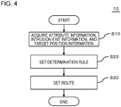
- Fig. 4 is a flowchart illustrating an example of a route setting process performed by the route setting apparatus 10.
- the acquisition unit 110 in the route setting apparatus 10 acquires attribute information of a moving object, entry-exit information, and target position information (Step S10 in Fig. 4 ).
- Step S10 in Fig. 4 A specific example of a method of acquiring each kind of information will be described below.
- the attribute information of the moving object is stored in, for example, a storage unit of the route setting apparatus 10.
- the acquisition unit 110 reads the attribute information of the moving object from the storage unit.
- the attribute information of the moving object may be stored in an external storage device.
- the acquisition unit 110 acquires the attribute information of the moving object from the storage device.
- the external storage device may store the attribute information of the moving object in association with moving-object identification information (for example, number written on a license plate, or vehicle identification number) for identifying the moving object.
- the acquisition unit 110 acquires the moving-object identification information and transmits the moving-object identification information to the external storage device.
- the storage device transmits the attribute information corresponding to the received moving-object identification information to the acquisition unit 110.
- the moving-object identification information may be stored in advance in the route setting apparatus 10 or may be acquired from the moving-object control apparatus 20.
- the acquisition unit 110 acquires the entry-exit information, for example, by using the movement route of the moving object and the map data.
- a movement route connecting a starting point (or the current position) and the target point is set, for example, using a car navigation program.
- Route information indicating the movement route includes an intersection in which the route to be set by the route setting apparatus 10. Therefore, the route setting apparatus 10 can determine the target intersection by using the route information, and can determine a road (described as an entry road below) on which the moving object travels when entering the intersection, and a road (described as an exit road below) on which the moving object travels when exiting from the intersection.
- the route setting apparatus 10 can use the map data stored in the map data storage unit 30.
- the map data includes information indicating the lane of the road (for example, the presence/absence of a right turn lane, or the presence/absence of a left turn lane) as information (described as road information below) indicating a road. Therefore, the moving-object control apparatus 20 can determine the lane in which the moving object is to pass in each of the entry road and the exit road, by using the route information and the map data.
- the road information includes information (described as end information below) indicating the end of the road at the intersection.
- the acquisition unit 110 acquires the end information on the entry road, as at least a portion of information indicating the entry position, and acquires the end information on the exit road, as at least a portion of information indicating the exit position.
- the end information indicates the end of the link.
- the acquisition unit 110 determines the lane in which the moving object is to pass on the entry road, and then recognizes a position corresponding to the end of a link in the lane as the entry position to the intersection.
- the acquisition unit 110 determines the lane in which the moving object is to pass on the exit road, and then recognizes a position corresponding to the end of a link in the lane as the exit position from the intersection.
- the entry-exit information may be input by a passenger of the moving object or a representative of the passenger.
- the passenger or the representative inputs the entry-exit information by selecting each of the entry position and the exit position in, for example, the intersection displayed on a display.
- a device for the input may be a terminal operated by a person who intends to perform an input, or may be a portion of the route setting apparatus 10.
- the target position information is stored in, for example, the map data storage unit 30.
- the target position information indicates a position at least near which the route of the moving object is to pass.
- the map data storage unit 30 preferably stores the target position information in association with each intersection. In this case, the acquisition unit 110 acquires the target position information associated with the target intersection.
- the target position information may be changed depending on the combination of information for specifying the intersection (or the information for specifying the type of intersection) and the attribute information of the moving object.
- the target position information is stored for each intersection (or each type of intersection) and for each piece of the attribute information of the moving object.
- the type of intersection is defined using the number of roads intersecting at the intersection, the number of lanes on each road, the angle at which the roads intersect at the intersection, and the like.
- the map data storage unit 30 stores, for example, the target position information for a small vehicle, the target position information for a large vehicle, and the target position information for a trailer at each intersection.
- the acquisition unit 110 selects and acquires the target position information corresponding to the attribute information of the moving object among pieces of the target position information associated with the target intersection.
- the target position information may be changed depending on the information for specifying the type of intersection.
- destination information may be stored for each type of intersection.
- the acquisition unit 110 determines the type of the target intersection by using the road information stored in the map data storage unit 30, and acquires the target position information corresponding to the determined type.
- the target position information may be stored further in association with the combination of the entry lane and the exit lane of the moving object.
- the acquisition unit 110 determines the entry lane and the exit lane at the target intersection by using movement data and the road information stored in the map data storage unit 30, and acquires the target position information corresponding to the combination of the determined lanes.
- the target position information may be stored in association with only the attribute information of the moving object.
- the acquisition unit 110 selects and acquires the target position information corresponding to the attribute information of the moving object.
- the determination rule setting unit 120 sets a determination rule, using the attribute information of the moving object, used when the route is set (Step S20).
- the determination rule is, for example, a program in which an arithmetic expression is described, and is stored in advance in, for example, the storage unit of the route setting apparatus 10 or the map data storage unit 30.
- the input to the program includes the entry-exit information and the target position information.
- the storage unit described above or the map data storage unit 30 may store a plurality of determination rules in association with the attribute information of the moving object for which the determination rule is to be used.
- the storage unit described above or the map data storage unit 30 stores a determination rule for a small vehicle, a determination rule for a large vehicle, and a determination rule for a trailer.
- the determination rule setting unit 120 reads the determination rule corresponding to the attribute information acquired in Step S10, from the storage unit or the map data storage unit 30.
- the determination rule setting unit 120 may set the determination rule by determining the value of the parameter using the attribute information acquired in Step S10, and putting the determined value into the above-described program.
- the storage unit described above or the map data storage unit 30 may store the above-described determination rule in association with each intersection.
- the determination rule differs depending on the intersection.
- the determination rule setting unit 120 reads the determination rule corresponding to the intersection to be processed, from the storage unit described above or the map data storage unit 30.
- a plurality of intersections may form a set, and one determination rule may be set for the formed set.
- the map data storage unit 30 may store the above-described determination rule as a portion of the map data, in a state of corresponding to the attribute information of the moving object and in a state of not being directly linked to the intersection.
- the route setting unit 130 sets the route on which the moving object is to move, by inputting the entry-exit information and the target position information into the determination rule set in Step S20 and perform processing (Step S30).
- Fig. 5 is a diagram illustrating a first example of a route R set for an intersection 800.
- the intersection 800 shown in Fig. 5 is a crossroad, and each road has two lanes.
- the route setting apparatus 10 sets a route R for a moving object 900 to turn right at the intersection.
- the map data stored in the map data storage unit 30 includes a link 840a of an entry road of the moving object 900, a link 840b of an exit road of the moving object 900, and target position information indicating a target position 830 at the intersection 800.
- the acquisition unit 110 reads the links 840a and 840b and the target position information from the map data storage unit 30.
- the acquisition unit 110 recognizes a portion of the traveling lane of the moving object 900 on the entry road, which corresponds to an end 842a of the link 840a on the intersection 800 side, as an entry position 810.
- the acquisition unit 110 recognizes a portion of the traveling lane of the moving object 900 on the exit road, which corresponds to an end 842b of the link 840b on the intersection 800 side, as an exit position 820.
- the route setting unit 130 sets the route R of the moving object 900 to connect the ends 842a and 842b. At this time, the route is set to overlap the target position 830 or to pass near the target position 830.
- the route R of the moving object 900 differs depending on the position of the target position 830. For example, as shown in Fig. 6 , as the target position 830 moves to the outer peripheral side of the intersection 800, the route R also moves to the outside of the intersection 800. Therefore, the route setting apparatus 10 can set the route R appropriate for the moving object 900 by changing the target position 830 in accordance with the attribute of the moving object 900.
- Figs. 7 and 8 are diagrams illustrating a second example of the route set for the intersection 800.
- at least one of the entry road and the exit road to and from the intersection 800 has a plurality of lanes.
- the map data stored in the map data storage unit 30 includes such information.
- the acquisition unit 110 in the route setting apparatus 10 uses the route information indicating the movement route of the moving object 900 to determine the lane in which the moving object 900 passes when entering the intersection 800, and the lane in which the moving object 900 passes when exiting from the intersection 800, and to set the determined lanes as a portion of the entry-exit information. That is, in the example shown in Figs. 7 and 8 , the entry-exit information includes information for determining one of the plurality of lanes.
- the acquisition unit 110 sets a position at which the determined lane overlaps the end of the link 840, as the entry position or the exit position to or from 8900. As shown in Figs. 7 and 8 , when the lane in which the moving object 900 enters the intersection 800 (or the lane in which the moving object 900 exits from the intersection 800) is different, the route R on which the moving object 900 is to pass is also different.
- the route setting apparatus 10 can set a route for causing the moving object 900 to pass through a predetermined portion on a road while turning, in accordance with the attribute of the moving object 900.
- the moving object 900 can turn the above-described predetermined portion on the road in a stable state.
- Fig. 9 is a diagram illustrating a usage environment of a route setting apparatus 10 according to a second embodiment.
- a moving object 900 includes a sensor 40 and an analysis apparatus 50.
- the sensor 40 is, for example, a light detection and ranging (LiDAR) or an imaging device.
- the analysis apparatus 50 analyzes data generated by the sensor 40 to generate information indicating the surrounding state of the moving object 900 (described as surrounding information below).
- the surrounding information includes the position of a stop line on a road and the position of a line or mark indicating the traveling road drawn in an intersection, in association with information for specifying the type of the line or mark.
- An acquisition unit 110 in a route setting apparatus 10 generates at least one of target position information and entry-exit information by using the above-described surrounding information.
- the route setting apparatus 10 sets a predetermined line or mark to be drawn in an intersection, as a target position.
- the acquisition unit 110 in the route setting apparatus 10 recognizes the position of the predetermined line or mark described above from the surrounding information, and sets the recognized position as the target position.
- the acquisition unit 110 recognizes the position of the stop line of the entry road from the surrounding information and sets the recognized position as an entry position.
- the acquisition unit 110 sets a start position of a lane for defining the exit road as an exit position.
- the moving object 900 can turn the above-described predetermined portion on the road in a stable state. Even though the map data storage unit 30 does not store the target position information, the target position information can be generated using the data generated by the sensor 40.
Landscapes
- Engineering & Computer Science (AREA)
- Radar, Positioning & Navigation (AREA)
- Remote Sensing (AREA)
- Automation & Control Theory (AREA)
- Transportation (AREA)
- Mechanical Engineering (AREA)
- Physics & Mathematics (AREA)
- General Physics & Mathematics (AREA)
- Human Computer Interaction (AREA)
- Navigation (AREA)
- Traffic Control Systems (AREA)
- Control Of Driving Devices And Active Controlling Of Vehicle (AREA)
Abstract
Description
- The present invention relates to a route setting apparatus, a route setting method, a program, and map data.
- In recent years, technological development for autonomously moving a moving object such as a vehicle to a destination has been promoted. In order to move the moving object autonomously to the destination, it is necessary to set a route for the moving object to move. The technology for setting such a route includes, for example, a technology related to a car navigation apparatus.
- Meanwhile, it is not possible for a general car navigation apparatus to set a route within an intersection. However, in the technology disclosed in Patent Document 1, it is disclosed that a traveling trajectory is calculated using an entry lane to an intersection, an exit lane from the intersection, and the center of the intersection.
- [Patent Document 1]
Japanese Patent Application Publication No. 2006-273230 - In a case where a moving object travels while turning, the route that is easy for the moving object to pass is different depending on attributes of the moving object. As an example of the problem to be solved by the present invention, a case where, when a moving object moves while turning, the route is changed depending on the attributes of the moving object is exemplified.
- According to the invention described in claim 1, there is provided a route setting apparatus that sets a route for causing a moving object to pass through a predetermined portion on a road while turning. The apparatus includes an acquisition unit that acquires attribute information of the moving object, entry-exit information for specifying an entry position to the predetermined portion and an exit position from the predetermined portion, and target position information indicating a target position located in the predetermined portion, a determination-rule setting unit that sets a determination rule using the attribute information, the determination rule being used when the route is determined using the entry-exit information and the target position information, and a route setting unit that sets the route using the determination rule, the entry-exit information, and the target position information.
- According to the invention described in
claim 10, there is provided a route setting method for setting a route when a moving obj ect passes through a predetermined portion on a road while turning. The method includes, by a computer, acquiring attribute information of the moving object, entry-exit information for specifying an entry position to the predetermined portion and an exit position from the predetermined portion, and target position information indicating a target position located in the predetermined portion, setting a determination rule using the attribute information, the determination rule being used when the route is determined using the entry-exit information and the target position information, and setting the route using the determination rule, the entry-exit information, and the target position information. - According to the invention described in claim 11, there is provided a program for causing a computer to function as the route setting apparatus according to any one of claims 1 to 9.
- According to the invention described in claim 12, there is provided map data including road information and a determination rule in association with attribute information of a moving object, the determination rule being used when setting a route for causing the moving object to pass through a predetermined portion on a road indicated by the road information while turning.
- According to the invention described in claim 13, there is provided map data including road information and a determination rule in association with a predetermined portion, the determination rule being used when setting a route for causing the moving object to pass through the predetermined portion on a road indicated by the road information while turning.
- The above-described objectives and other objectives, features and advantages will be further clarified by the preferred embodiments described below and the accompanying drawings.
-
-
Fig. 1 is a diagram illustrating a usage environment of a route setting apparatus according to a first embodiment. -
Fig. 2 is a diagram illustrating a functional configuration of the route setting apparatus. -
Fig. 3 is a diagram illustrating an example of a hardware configuration of the route setting apparatus. -
Fig. 4 is a flowchart illustrating an example of a route setting process performed by the route setting apparatus. -
Fig. 5 is a diagram illustrating a first example of a route R set for an intersection. -
Fig. 6 is a diagram illustrating a modification example ofFig. 5 . -
Fig. 7 is a diagram illustrating a second example of the route set for an intersection. -
Fig. 8 is a diagram illustrating a modification example ofFig. 6 . -
Fig. 9 is a diagram illustrating a usage environment of a route setting apparatus according to a second embodiment. - Hereinafter, embodiments of the present invention will be described with reference to the drawings. In all drawings, similar components are denoted by the similar reference signs, and description thereof will not be repeated.
-
Fig. 1 is a diagram illustrating a usage environment of aroute setting apparatus 10 according to a first embodiment. Theroute setting apparatus 10 is an apparatus that sets a route for causing a moving object to pass through a predetermined portion on a road while turning, and is used together with a mapdata storage unit 30. Theroute setting apparatus 10 uses map data stored in the mapdata storage unit 30 when setting the above-described route. The map data stored in the mapdata storage unit 30 includes various kinds of information used when theroute setting apparatus 10 sets the above-described route. - The moving object is, for example, a vehicle that travels on a road, but is not limited to this. In the example shown in
Fig. 1 , theroute setting apparatus 10 is used together with a moving-object control apparatus 20. The moving-object control apparatus 20 is an apparatus that controls the movement of a moving object, and moves the moving object along the route set by theroute setting apparatus 10. The moving-object control apparatus 20 is, for example, an autonomous driving control apparatus for a vehicle that is autonomously driven, and is mounted on, for example, a moving object to be controlled. In this case, theroute setting apparatus 10 may be located outside the moving object to be controlled, or may be mounted on the moving object as a portion of the moving-object control apparatus 20. Both theroute setting apparatus 10 and the moving-object control apparatus 20 may be located outside the moving object. - The map
data storage unit 30 may also be mounted on the moving object to be controlled, or may be located outside the moving object. The mapdata storage unit 30 may be a portion of theroute setting apparatus 10. In a case where the moving-object control apparatus 20 and the mapdata storage unit 30 are installed at a location different from the location of theroute setting apparatus 10, the moving-object control apparatus 20 and the mapdata storage unit 30 communicate with theroute setting apparatus 10 via a public communication network such as the Internet. At least a portion of the public communication network is wireless communication. - The predetermined portion on the road is, for example, an intersection, but may be a portion is bent by a predetermined angle (for example, 45°) or larger, or may be a crank. The intersection may be a three-way junction, a four-way junction, or a five-forked road or more. Description will be made below on the assumption that the predetermined portion is an intersection. Even though the predetermined portion is other than the intersection, the configuration of various kinds of data (including map data) and the operation of the
route setting apparatus 10 are the same as those in the examples described below. -
Fig. 2 is a diagram illustrating a functional configuration of theroute setting apparatus 10. Theroute setting apparatus 10 includes anacquisition unit 110, a determinationrule setting unit 120, and aroute setting unit 130. - An
acquisition unit 110 acquires attribute information of a moving object, entry-exit information, and target position information. The entry-exit information is information for specifying an entry position to an intersection and an exit position from the intersection. The entry position and the exit position indicated by the entry-exit information may be points or information (for example, line) having a certain area or width. The attribute information of the moving object is information regarding the moving object. In a case where the moving object is a vehicle, the attribute information of the moving object includes, for example, at least one of an overall length, a width, a minimum turning radius, a wheelbase, a front overhang, a rear overhang, and a vehicle type classification of the vehicle. The target position information is information indicating a target position located in the intersection. The target position indicates a position at least near which a route of the moving object is to pass. - The determination
rule setting unit 120 sets a rule (described as a determination rule below) used when a route is determined, by using the attribute information of the moving object. The determination rule is used together with the entry-exit information and the target position information described above. Theroute setting unit 130 sets the above-described route using the determination rule set by the determinationrule setting unit 120, and the entry-exit information and the target position information acquired by theacquisition unit 110. -
Fig. 3 is a diagram illustrating an example of the hardware configuration of theroute setting apparatus 10. The main configuration of theroute setting apparatus 10 is realized using an integrated circuit. The integrated circuit includes abus 182, aprocessor 184, amemory 186, astorage device 188, an input/output interface 190, and anetwork interface 192. Thebus 182 is a data transmission line for theprocessor 184, thememory 186, thestorage device 188, the input/output interface 190, and thenetwork interface 192 to transmit and receive data to and from each other. A method of connecting theprocessors 184 and the like to each other is not limited to the bus connection. Theprocessor 184 is an arithmetic processing unit realized using a microprocessor or the like. Thememory 186 is a memory realized using a random access memory (RAM) or the like. Thestorage device 188 is a storage device realized using a read only memory (ROM), a flash memory, or the like. - The input/
output interface 190 is an interface for connecting theroute setting apparatus 10 to peripheral devices. - The
network interface 192 is an interface for connecting theroute setting apparatus 10 to a communication network. A method of connecting thenetwork interface 192 to the communication network may be a wireless connection or a wired connection. - The
storage device 188 stores a program module for realizing each functional element of theroute setting apparatus 10. Theprocessor 184 reads and executes the program module into thememory 186 to realize the functions of theroute setting apparatus 10. Thestorage device 188 may also function as the mapdata storage unit 30. - The hardware configuration of the integrated circuit described above is not limited to the configuration shown in
Fig. 3 . For example, the program module may be stored in thememory 186. In this case, the integrated circuit may not include thestorage device 188. -
Fig. 4 is a flowchart illustrating an example of a route setting process performed by theroute setting apparatus 10. Firstly, theacquisition unit 110 in theroute setting apparatus 10 acquires attribute information of a moving object, entry-exit information, and target position information (Step S10 inFig. 4 ). A specific example of a method of acquiring each kind of information will be described below. - The attribute information of the moving object is stored in, for example, a storage unit of the
route setting apparatus 10. In this case, theacquisition unit 110 reads the attribute information of the moving object from the storage unit. - The attribute information of the moving object may be stored in an external storage device. In this case, the
acquisition unit 110 acquires the attribute information of the moving object from the storage device. The external storage device may store the attribute information of the moving object in association with moving-object identification information (for example, number written on a license plate, or vehicle identification number) for identifying the moving object. In this case, theacquisition unit 110 acquires the moving-object identification information and transmits the moving-object identification information to the external storage device. The storage device transmits the attribute information corresponding to the received moving-object identification information to theacquisition unit 110. The moving-object identification information may be stored in advance in theroute setting apparatus 10 or may be acquired from the moving-object control apparatus 20. - The
acquisition unit 110 acquires the entry-exit information, for example, by using the movement route of the moving object and the map data. - Specifically, in the moving-
object control apparatus 20 of the moving object, a movement route connecting a starting point (or the current position) and the target point is set, for example, using a car navigation program. Route information indicating the movement route includes an intersection in which the route to be set by theroute setting apparatus 10. Therefore, theroute setting apparatus 10 can determine the target intersection by using the route information, and can determine a road (described as an entry road below) on which the moving object travels when entering the intersection, and a road (described as an exit road below) on which the moving object travels when exiting from the intersection. - As described above, the
route setting apparatus 10 can use the map data stored in the mapdata storage unit 30. The map data includes information indicating the lane of the road (for example, the presence/absence of a right turn lane, or the presence/absence of a left turn lane) as information (described as road information below) indicating a road. Therefore, the moving-object control apparatus 20 can determine the lane in which the moving object is to pass in each of the entry road and the exit road, by using the route information and the map data. - In the map data, the road information includes information (described as end information below) indicating the end of the road at the intersection. The
acquisition unit 110 acquires the end information on the entry road, as at least a portion of information indicating the entry position, and acquires the end information on the exit road, as at least a portion of information indicating the exit position. - Consider a case where the road information is defined using nodes and links. In this case, the end information indicates the end of the link. The
acquisition unit 110 determines the lane in which the moving object is to pass on the entry road, and then recognizes a position corresponding to the end of a link in the lane as the entry position to the intersection. Theacquisition unit 110 determines the lane in which the moving object is to pass on the exit road, and then recognizes a position corresponding to the end of a link in the lane as the exit position from the intersection. - The entry-exit information may be input by a passenger of the moving object or a representative of the passenger. In this case, the passenger or the representative inputs the entry-exit information by selecting each of the entry position and the exit position in, for example, the intersection displayed on a display. A device for the input may be a terminal operated by a person who intends to perform an input, or may be a portion of the
route setting apparatus 10. - The target position information is stored in, for example, the map
data storage unit 30. As described above, the target position information indicates a position at least near which the route of the moving object is to pass. The mapdata storage unit 30 preferably stores the target position information in association with each intersection. In this case, theacquisition unit 110 acquires the target position information associated with the target intersection. - The target position information may be changed depending on the combination of information for specifying the intersection (or the information for specifying the type of intersection) and the attribute information of the moving object. For example, the target position information is stored for each intersection (or each type of intersection) and for each piece of the attribute information of the moving object. Here, the type of intersection is defined using the number of roads intersecting at the intersection, the number of lanes on each road, the angle at which the roads intersect at the intersection, and the like. In this case, the map
data storage unit 30 stores, for example, the target position information for a small vehicle, the target position information for a large vehicle, and the target position information for a trailer at each intersection. In this case, theacquisition unit 110 selects and acquires the target position information corresponding to the attribute information of the moving object among pieces of the target position information associated with the target intersection. - In the above two examples, the target position information may be changed depending on the information for specifying the type of intersection. For example, destination information may be stored for each type of intersection. In this case, the
acquisition unit 110 determines the type of the target intersection by using the road information stored in the mapdata storage unit 30, and acquires the target position information corresponding to the determined type. - In the above three examples, the target position information may be stored further in association with the combination of the entry lane and the exit lane of the moving object. In this case, the
acquisition unit 110 determines the entry lane and the exit lane at the target intersection by using movement data and the road information stored in the mapdata storage unit 30, and acquires the target position information corresponding to the combination of the determined lanes. - The target position information may be stored in association with only the attribute information of the moving object. The
acquisition unit 110 selects and acquires the target position information corresponding to the attribute information of the moving object. - Then, the determination
rule setting unit 120 sets a determination rule, using the attribute information of the moving object, used when the route is set (Step S20). The determination rule is, for example, a program in which an arithmetic expression is described, and is stored in advance in, for example, the storage unit of theroute setting apparatus 10 or the mapdata storage unit 30. The input to the program includes the entry-exit information and the target position information. - The storage unit described above or the map
data storage unit 30 may store a plurality of determination rules in association with the attribute information of the moving object for which the determination rule is to be used. For example, the storage unit described above or the mapdata storage unit 30 stores a determination rule for a small vehicle, a determination rule for a large vehicle, and a determination rule for a trailer. The determinationrule setting unit 120 reads the determination rule corresponding to the attribute information acquired in Step S10, from the storage unit or the mapdata storage unit 30. - In a case where the above-described arithmetic expression includes at least one parameter, the determination
rule setting unit 120 may set the determination rule by determining the value of the parameter using the attribute information acquired in Step S10, and putting the determined value into the above-described program. - In any of the above examples, the storage unit described above or the map
data storage unit 30 may store the above-described determination rule in association with each intersection. In this case, the determination rule differs depending on the intersection. The determinationrule setting unit 120 reads the determination rule corresponding to the intersection to be processed, from the storage unit described above or the mapdata storage unit 30. A plurality of intersections may form a set, and one determination rule may be set for the formed set. - The map
data storage unit 30 may store the above-described determination rule as a portion of the map data, in a state of corresponding to the attribute information of the moving object and in a state of not being directly linked to the intersection. - Then, the
route setting unit 130 sets the route on which the moving object is to move, by inputting the entry-exit information and the target position information into the determination rule set in Step S20 and perform processing (Step S30). -
Fig. 5 is a diagram illustrating a first example of a route R set for anintersection 800. Theintersection 800 shown inFig. 5 is a crossroad, and each road has two lanes. Theroute setting apparatus 10 sets a route R for a movingobject 900 to turn right at the intersection. - Specifically, the map data stored in the map
data storage unit 30 includes alink 840a of an entry road of the movingobject 900, alink 840b of an exit road of the movingobject 900, and target position information indicating atarget position 830 at theintersection 800. When theintersection 800 is designated, theacquisition unit 110 reads thelinks data storage unit 30. Theacquisition unit 110 recognizes a portion of the traveling lane of the movingobject 900 on the entry road, which corresponds to anend 842a of thelink 840a on theintersection 800 side, as anentry position 810. Theacquisition unit 110 recognizes a portion of the traveling lane of the movingobject 900 on the exit road, which corresponds to anend 842b of thelink 840b on theintersection 800 side, as anexit position 820. - The
route setting unit 130 sets the route R of the movingobject 900 to connect theends target position 830 or to pass near thetarget position 830. - The route R of the moving
object 900 differs depending on the position of thetarget position 830. For example, as shown inFig. 6 , as thetarget position 830 moves to the outer peripheral side of theintersection 800, the route R also moves to the outside of theintersection 800. Therefore, theroute setting apparatus 10 can set the route R appropriate for the movingobject 900 by changing thetarget position 830 in accordance with the attribute of the movingobject 900. -
Figs. 7 and8 are diagrams illustrating a second example of the route set for theintersection 800. In the example shown inFigs. 7 and8 , at least one of the entry road and the exit road to and from the intersection 800 (both in the example shown inFigs. 7 and8 ) has a plurality of lanes. The map data stored in the mapdata storage unit 30 includes such information. Theacquisition unit 110 in theroute setting apparatus 10 uses the route information indicating the movement route of the movingobject 900 to determine the lane in which the movingobject 900 passes when entering theintersection 800, and the lane in which the movingobject 900 passes when exiting from theintersection 800, and to set the determined lanes as a portion of the entry-exit information. That is, in the example shown inFigs. 7 and8 , the entry-exit information includes information for determining one of the plurality of lanes. - The
acquisition unit 110 sets a position at which the determined lane overlaps the end of the link 840, as the entry position or the exit position to or from 8900. As shown inFigs. 7 and8 , when the lane in which the movingobject 900 enters the intersection 800 (or the lane in which the movingobject 900 exits from the intersection 800) is different, the route R on which the movingobject 900 is to pass is also different. - As described above, according to the present embodiment, the
route setting apparatus 10 can set a route for causing the movingobject 900 to pass through a predetermined portion on a road while turning, in accordance with the attribute of the movingobject 900. Thus, the movingobject 900 can turn the above-described predetermined portion on the road in a stable state. -
Fig. 9 is a diagram illustrating a usage environment of aroute setting apparatus 10 according to a second embodiment. In the example shown inFig. 9 , a movingobject 900 includes asensor 40 and ananalysis apparatus 50. Thesensor 40 is, for example, a light detection and ranging (LiDAR) or an imaging device. Theanalysis apparatus 50 analyzes data generated by thesensor 40 to generate information indicating the surrounding state of the moving object 900 (described as surrounding information below). The surrounding information includes the position of a stop line on a road and the position of a line or mark indicating the traveling road drawn in an intersection, in association with information for specifying the type of the line or mark. Anacquisition unit 110 in aroute setting apparatus 10 generates at least one of target position information and entry-exit information by using the above-described surrounding information. - For example, the
route setting apparatus 10 sets a predetermined line or mark to be drawn in an intersection, as a target position. Theacquisition unit 110 in theroute setting apparatus 10 recognizes the position of the predetermined line or mark described above from the surrounding information, and sets the recognized position as the target position. - The
acquisition unit 110 recognizes the position of the stop line of the entry road from the surrounding information and sets the recognized position as an entry position. Theacquisition unit 110 sets a start position of a lane for defining the exit road as an exit position. - Also in the present embodiment, similar to the first embodiment, the moving
object 900 can turn the above-described predetermined portion on the road in a stable state. Even though the mapdata storage unit 30 does not store the target position information, the target position information can be generated using the data generated by thesensor 40. - Hitherto, the embodiments and examples have been described above with reference to the drawings, but these are examples of the present invention, and various configurations other than the above description can be adopted.
- This application claims priority on the basis of
Japanese application Japanese Patent Application No. 2018-213529 filed on November 14, 2018 -
- 10:
- route setting apparatus
- 20:
- moving-object control apparatus
- 30:
- map data storage unit
- 40:
- sensor
- 50:
- analysis apparatus
- 110:
- acquisition unit
- 120:
- determination rule setting unit
- 130:
- route setting unit
- 800:
- intersection
- 810:
- entry position
- 820:
- exit position
- 830:
- target position
- 840, 840a, 840b:
- link
- 842a, 842b:
- end
- 900:
- moving object
- R:
- route
Claims (13)
- A route setting apparatus that sets a route for causing a moving obj ect to pass through a predetermined portion on a road while turning, the apparatus comprising:an acquisition unit that acquires attribute information of the moving object, entry-exit information for specifying an entry position to the predetermined portion and an exit position from the predetermined portion, and target position information indicating a target position located in the predetermined portion;a determination-rule setting unit that sets a determination rule using the attribute information, the determination rule being used when the route is determined using the entry-exit information and the target position information; anda route setting unit that sets the route using the determination rule, the entry-exit information, and the target position information.
- The route setting apparatus according to claim 1, wherein the predetermined portion is an intersection.
- The route setting apparatus according to claim 2, whereinat least one of a road on an entry side to the intersection and a road on an exit side includes a plurality of lanes, andthe entry-exit information includes information for specifying one of the plurality of lanes, as information indicating the entry position or the exit position.
- The route setting apparatus according to claim 2 or 3, whereinthe route setting apparatus is capable of using map information,the map information includes end information indicating a position of an end of a lane on the intersection side, the lane being connected to the intersection,the entry position to the intersection and the exit position from the intersection are positions of ends of the intersection,the acquisition unit acquires the end information as at least a portion of the entry-exit information, andthe determination rule includes an arithmetic expression for calculating the route.
- The route setting apparatus according to any one of claims 1 to 4, whereinthe moving object is a vehicle, andthe attribute information includes at least one of an overall length, a width, a minimum turning radius, a wheelbase, a front overhang, a rear overhang, and a vehicle type classification of the vehicle.
- The route setting apparatus according to any one of claims 1 to 5, whereinthe target position information is associated with the attribute information, andthe acquisition unit acquires the target position information corresponding to the attribute information acquired by the acquisition unit.
- The route setting apparatus according to any one of claims 1 to 6, whereinthe determination rule is associated with an attribute of the predetermined portion, andthe acquisition unit further acquires the attribute of the predetermined portion and acquires the determination rule corresponding to the attribute.
- The route setting apparatus according to any one of claims 1 to 7, wherein
the acquisition unit acquires the target position information from a map information storage unit that stores map information. - The route setting apparatus according to any one of claims 1 to 7, wherein
the target position information is generated using data generated by a sensor attached to the moving object. - A route setting method of setting a route when a moving object passes through a predetermined portion on a road while turning, the method comprising:by a computer,acquiring attribute information of the moving object, entry-exit information for specifying an entry position to the predetermined portion and an exit position from the predetermined portion, and target position information indicating a target position located in the predetermined portion;setting a determination rule using the attribute information, the determination rule being used when the route is determined using the entry-exit information and the target position information; andsetting the route using the determination rule, the entry-exit information, and the target position information.
- A program for causing a computer to function as the route setting apparatus according to any one of claims 1 to 9.
- Map data including road information and a determination rule in a state of being associated with attribute information of a moving object, the determination rule being used when setting a route for causing the moving object to pass through a predetermined portion on a road indicated by the road information while turning.
- Map data including road information and a determination rule in a state of being associated with a predetermined portion, the determination rule being used when setting a route for causing a moving object to pass through the predetermined portion on a road indicated by the road information while turning.
Applications Claiming Priority (2)
| Application Number | Priority Date | Filing Date | Title |
|---|---|---|---|
| JP2018213529 | 2018-11-14 | ||
| PCT/JP2019/044274 WO2020100868A1 (en) | 2018-11-14 | 2019-11-12 | Route setting device, route setting method, program, and map data |
Publications (3)
| Publication Number | Publication Date |
|---|---|
| EP3882575A1 true EP3882575A1 (en) | 2021-09-22 |
| EP3882575A4 EP3882575A4 (en) | 2022-08-24 |
| EP3882575B1 EP3882575B1 (en) | 2025-04-16 |
Family
ID=70730265
Family Applications (1)
| Application Number | Title | Priority Date | Filing Date |
|---|---|---|---|
| EP19885389.7A Active EP3882575B1 (en) | 2018-11-14 | 2019-11-12 | Route setting device, route setting method and program |
Country Status (4)
| Country | Link |
|---|---|
| US (1) | US20220018680A1 (en) |
| EP (1) | EP3882575B1 (en) |
| JP (1) | JP7252253B2 (en) |
| WO (1) | WO2020100868A1 (en) |
Families Citing this family (2)
| Publication number | Priority date | Publication date | Assignee | Title |
|---|---|---|---|---|
| JP7200820B2 (en) * | 2019-05-13 | 2023-01-10 | 株式会社デンソー | Traffic sign identification device and driving support device |
| CN115375241A (en) * | 2022-08-30 | 2022-11-22 | 中国银行股份有限公司 | Route planning method, device, storage medium and equipment |
Family Cites Families (9)
| Publication number | Priority date | Publication date | Assignee | Title |
|---|---|---|---|---|
| JP2004294142A (en) * | 2003-03-26 | 2004-10-21 | Nissan Diesel Motor Co Ltd | Travel route information storage device |
| JP2006273230A (en) | 2005-03-30 | 2006-10-12 | Aisin Aw Co Ltd | Vehicle controller and vehicle control method |
| JP5353097B2 (en) * | 2008-07-22 | 2013-11-27 | 朝日航洋株式会社 | Road network data generation device, intersection lane generation device, and method and program thereof |
| US10013508B2 (en) * | 2014-10-07 | 2018-07-03 | Toyota Motor Engineering & Manufacturing North America, Inc. | Joint probabilistic modeling and inference of intersection structure |
| DE112016005700T5 (en) * | 2016-01-14 | 2018-09-27 | Ford Global Technologies, Llc | Reversing assistance based on maneuvering difficulty |
| CN105575151B (en) * | 2016-01-19 | 2017-09-22 | 长安大学 | Consider the GPS navigation method for optimizing route of type of vehicle and level-crossing delay |
| JP7016214B2 (en) * | 2016-11-29 | 2022-02-04 | アルパイン株式会社 | Travelable area setting device and travelable area setting method |
| JP6544348B2 (en) * | 2016-12-22 | 2019-07-17 | トヨタ自動車株式会社 | Vehicle driving support device |
| US20200370915A1 (en) * | 2018-03-23 | 2020-11-26 | Mitsubishi Electric Corporation | Travel assist system, travel assist method, and computer readable medium |
-
2019
- 2019-11-12 JP JP2020555705A patent/JP7252253B2/en active Active
- 2019-11-12 US US17/294,229 patent/US20220018680A1/en not_active Abandoned
- 2019-11-12 EP EP19885389.7A patent/EP3882575B1/en active Active
- 2019-11-12 WO PCT/JP2019/044274 patent/WO2020100868A1/en not_active Ceased
Also Published As
| Publication number | Publication date |
|---|---|
| EP3882575A4 (en) | 2022-08-24 |
| JPWO2020100868A1 (en) | 2020-05-22 |
| EP3882575B1 (en) | 2025-04-16 |
| WO2020100868A1 (en) | 2020-05-22 |
| JP7252253B2 (en) | 2023-04-04 |
| US20220018680A1 (en) | 2022-01-20 |
Similar Documents
| Publication | Publication Date | Title |
|---|---|---|
| US12013701B2 (en) | Systems and methods for communicating intent of an autonomous vehicle | |
| RU2682151C1 (en) | Device for determination of environment, motion assistance equipment and method for determination of environment | |
| RU2682112C1 (en) | Driving planning device, motion assistance equipment and driving planning method | |
| US10809723B2 (en) | Method and apparatus for generating information | |
| US20200160714A1 (en) | Driving assistance apparatus, driving assistance system, and driving assistance method | |
| JP6809611B2 (en) | Driving support method and driving support device | |
| CN107683234B (en) | Surrounding environment recognition device and computer program product | |
| RU2682095C1 (en) | Device for determination of environment, motion assistance equipment and method for determination of environment | |
| EP3715162B1 (en) | Device and method for displaying content | |
| CN111457931B (en) | Local path replanning control method, device, system and storage medium for autonomous vehicle | |
| JP6920984B2 (en) | Driving support device | |
| EP3627110B1 (en) | Method for planning trajectory of vehicle | |
| JP6512022B2 (en) | Driving support device | |
| JP2018055637A (en) | Driving assistance device | |
| US20200284610A1 (en) | Driving Assistance Method and Driving Assistance Device | |
| KR20180069492A (en) | Apparatus and Method for controlling Advanced Driver Assistance System | |
| EP3882575B1 (en) | Route setting device, route setting method and program | |
| EP3327694A1 (en) | Scene evaluation device, travel support device, and scene evaluation method | |
| US20220073103A1 (en) | Metacognition-based autonomous driving correction device and method | |
| CN119773760B (en) | Driving decision generation method, device, electronic equipment and storage medium | |
| JP2011002893A (en) | Driving support device and program | |
| US12071172B2 (en) | Method for visualizing a steering angle and lateral boundaries for driver assist and safer driving | |
| JP2022051874A (en) | Mobility support device, mobility support method and program for mobility support | |
| CN114132343A (en) | Vehicle tracking method, device, system and computer readable storage medium | |
| JP7058960B2 (en) | A method for determining the road shape and a device for determining the road shape |
Legal Events
| Date | Code | Title | Description |
|---|---|---|---|
| STAA | Information on the status of an ep patent application or granted ep patent |
Free format text: STATUS: THE INTERNATIONAL PUBLICATION HAS BEEN MADE |
|
| PUAI | Public reference made under article 153(3) epc to a published international application that has entered the european phase |
Free format text: ORIGINAL CODE: 0009012 |
|
| STAA | Information on the status of an ep patent application or granted ep patent |
Free format text: STATUS: REQUEST FOR EXAMINATION WAS MADE |
|
| 17P | Request for examination filed |
Effective date: 20210614 |
|
| AK | Designated contracting states |
Kind code of ref document: A1 Designated state(s): AL AT BE BG CH CY CZ DE DK EE ES FI FR GB GR HR HU IE IS IT LI LT LU LV MC MK MT NL NO PL PT RO RS SE SI SK SM TR |
|
| DAV | Request for validation of the european patent (deleted) | ||
| DAX | Request for extension of the european patent (deleted) | ||
| RAP1 | Party data changed (applicant data changed or rights of an application transferred) |
Owner name: PIP HOLDINGS K.K. |
|
| RAP3 | Party data changed (applicant data changed or rights of an application transferred) |
Owner name: INCREMENT P CORPORATION |
|
| A4 | Supplementary search report drawn up and despatched |
Effective date: 20220721 |
|
| RIC1 | Information provided on ipc code assigned before grant |
Ipc: G08G 1/0969 20060101ALI20220715BHEP Ipc: B60W 30/10 20060101ALI20220715BHEP Ipc: G01C 21/34 20060101AFI20220715BHEP |
|
| RAP3 | Party data changed (applicant data changed or rights of an application transferred) |
Owner name: GEOTECHNOLOGIES, INC. |
|
| GRAP | Despatch of communication of intention to grant a patent |
Free format text: ORIGINAL CODE: EPIDOSNIGR1 |
|
| STAA | Information on the status of an ep patent application or granted ep patent |
Free format text: STATUS: GRANT OF PATENT IS INTENDED |
|
| INTG | Intention to grant announced |
Effective date: 20241204 |
|
| GRAS | Grant fee paid |
Free format text: ORIGINAL CODE: EPIDOSNIGR3 |
|
| GRAA | (expected) grant |
Free format text: ORIGINAL CODE: 0009210 |
|
| STAA | Information on the status of an ep patent application or granted ep patent |
Free format text: STATUS: THE PATENT HAS BEEN GRANTED |
|
| AK | Designated contracting states |
Kind code of ref document: B1 Designated state(s): AL AT BE BG CH CY CZ DE DK EE ES FI FR GB GR HR HU IE IS IT LI LT LU LV MC MK MT NL NO PL PT RO RS SE SI SK SM TR |
|
| REG | Reference to a national code |
Ref country code: GB Ref legal event code: FG4D |
|
| P01 | Opt-out of the competence of the unified patent court (upc) registered |
Free format text: CASE NUMBER: APP_13849/2025 Effective date: 20250320 |
|
| REG | Reference to a national code |
Ref country code: CH Ref legal event code: EP Ref country code: DE Ref legal event code: R096 Ref document number: 602019068846 Country of ref document: DE |
|
| REG | Reference to a national code |
Ref country code: IE Ref legal event code: FG4D |
|
| REG | Reference to a national code |
Ref country code: NL Ref legal event code: MP Effective date: 20250416 |
|
| PG25 | Lapsed in a contracting state [announced via postgrant information from national office to epo] |
Ref country code: NL Free format text: LAPSE BECAUSE OF FAILURE TO SUBMIT A TRANSLATION OF THE DESCRIPTION OR TO PAY THE FEE WITHIN THE PRESCRIBED TIME-LIMIT Effective date: 20250416 |
|
| REG | Reference to a national code |
Ref country code: AT Ref legal event code: MK05 Ref document number: 1785956 Country of ref document: AT Kind code of ref document: T Effective date: 20250416 |
|
| PG25 | Lapsed in a contracting state [announced via postgrant information from national office to epo] |
Ref country code: ES Free format text: LAPSE BECAUSE OF FAILURE TO SUBMIT A TRANSLATION OF THE DESCRIPTION OR TO PAY THE FEE WITHIN THE PRESCRIBED TIME-LIMIT Effective date: 20250416 Ref country code: PT Free format text: LAPSE BECAUSE OF FAILURE TO SUBMIT A TRANSLATION OF THE DESCRIPTION OR TO PAY THE FEE WITHIN THE PRESCRIBED TIME-LIMIT Effective date: 20250818 Ref country code: FI Free format text: LAPSE BECAUSE OF FAILURE TO SUBMIT A TRANSLATION OF THE DESCRIPTION OR TO PAY THE FEE WITHIN THE PRESCRIBED TIME-LIMIT Effective date: 20250416 |
|
| REG | Reference to a national code |
Ref country code: LT Ref legal event code: MG9D |
|
| PG25 | Lapsed in a contracting state [announced via postgrant information from national office to epo] |
Ref country code: NO Free format text: LAPSE BECAUSE OF FAILURE TO SUBMIT A TRANSLATION OF THE DESCRIPTION OR TO PAY THE FEE WITHIN THE PRESCRIBED TIME-LIMIT Effective date: 20250716 Ref country code: GR Free format text: LAPSE BECAUSE OF FAILURE TO SUBMIT A TRANSLATION OF THE DESCRIPTION OR TO PAY THE FEE WITHIN THE PRESCRIBED TIME-LIMIT Effective date: 20250717 |
|
| PG25 | Lapsed in a contracting state [announced via postgrant information from national office to epo] |
Ref country code: PL Free format text: LAPSE BECAUSE OF FAILURE TO SUBMIT A TRANSLATION OF THE DESCRIPTION OR TO PAY THE FEE WITHIN THE PRESCRIBED TIME-LIMIT Effective date: 20250416 |
|
| PG25 | Lapsed in a contracting state [announced via postgrant information from national office to epo] |
Ref country code: BG Free format text: LAPSE BECAUSE OF FAILURE TO SUBMIT A TRANSLATION OF THE DESCRIPTION OR TO PAY THE FEE WITHIN THE PRESCRIBED TIME-LIMIT Effective date: 20250416 |
|
| PG25 | Lapsed in a contracting state [announced via postgrant information from national office to epo] |
Ref country code: HR Free format text: LAPSE BECAUSE OF FAILURE TO SUBMIT A TRANSLATION OF THE DESCRIPTION OR TO PAY THE FEE WITHIN THE PRESCRIBED TIME-LIMIT Effective date: 20250416 |
|
| PG25 | Lapsed in a contracting state [announced via postgrant information from national office to epo] |
Ref country code: AT Free format text: LAPSE BECAUSE OF FAILURE TO SUBMIT A TRANSLATION OF THE DESCRIPTION OR TO PAY THE FEE WITHIN THE PRESCRIBED TIME-LIMIT Effective date: 20250416 |
|
| PG25 | Lapsed in a contracting state [announced via postgrant information from national office to epo] |
Ref country code: RS Free format text: LAPSE BECAUSE OF FAILURE TO SUBMIT A TRANSLATION OF THE DESCRIPTION OR TO PAY THE FEE WITHIN THE PRESCRIBED TIME-LIMIT Effective date: 20250716 |
|
| PG25 | Lapsed in a contracting state [announced via postgrant information from national office to epo] |
Ref country code: IS Free format text: LAPSE BECAUSE OF FAILURE TO SUBMIT A TRANSLATION OF THE DESCRIPTION OR TO PAY THE FEE WITHIN THE PRESCRIBED TIME-LIMIT Effective date: 20250816 |
|
| PG25 | Lapsed in a contracting state [announced via postgrant information from national office to epo] |
Ref country code: LV Free format text: LAPSE BECAUSE OF FAILURE TO SUBMIT A TRANSLATION OF THE DESCRIPTION OR TO PAY THE FEE WITHIN THE PRESCRIBED TIME-LIMIT Effective date: 20250416 |
|
| PGFP | Annual fee paid to national office [announced via postgrant information from national office to epo] |
Ref country code: DE Payment date: 20251119 Year of fee payment: 7 |
|
| PG25 | Lapsed in a contracting state [announced via postgrant information from national office to epo] |
Ref country code: DK Free format text: LAPSE BECAUSE OF FAILURE TO SUBMIT A TRANSLATION OF THE DESCRIPTION OR TO PAY THE FEE WITHIN THE PRESCRIBED TIME-LIMIT Effective date: 20250416 Ref country code: SM Free format text: LAPSE BECAUSE OF FAILURE TO SUBMIT A TRANSLATION OF THE DESCRIPTION OR TO PAY THE FEE WITHIN THE PRESCRIBED TIME-LIMIT Effective date: 20250416 |
|
| PGFP | Annual fee paid to national office [announced via postgrant information from national office to epo] |
Ref country code: IT Payment date: 20251126 Year of fee payment: 7 |
|
| PGFP | Annual fee paid to national office [announced via postgrant information from national office to epo] |
Ref country code: FR Payment date: 20251106 Year of fee payment: 7 |
|
| REG | Reference to a national code |
Ref country code: DE Ref legal event code: R097 Ref document number: 602019068846 Country of ref document: DE |
|
| PG25 | Lapsed in a contracting state [announced via postgrant information from national office to epo] |
Ref country code: CZ Free format text: LAPSE BECAUSE OF FAILURE TO SUBMIT A TRANSLATION OF THE DESCRIPTION OR TO PAY THE FEE WITHIN THE PRESCRIBED TIME-LIMIT Effective date: 20250416 |
|
| PG25 | Lapsed in a contracting state [announced via postgrant information from national office to epo] |
Ref country code: EE Free format text: LAPSE BECAUSE OF FAILURE TO SUBMIT A TRANSLATION OF THE DESCRIPTION OR TO PAY THE FEE WITHIN THE PRESCRIBED TIME-LIMIT Effective date: 20250416 |
|
| PG25 | Lapsed in a contracting state [announced via postgrant information from national office to epo] |
Ref country code: RO Free format text: LAPSE BECAUSE OF FAILURE TO SUBMIT A TRANSLATION OF THE DESCRIPTION OR TO PAY THE FEE WITHIN THE PRESCRIBED TIME-LIMIT Effective date: 20250416 Ref country code: SK Free format text: LAPSE BECAUSE OF FAILURE TO SUBMIT A TRANSLATION OF THE DESCRIPTION OR TO PAY THE FEE WITHIN THE PRESCRIBED TIME-LIMIT Effective date: 20250416 |
|
| PLBE | No opposition filed within time limit |
Free format text: ORIGINAL CODE: 0009261 |
|
| STAA | Information on the status of an ep patent application or granted ep patent |
Free format text: STATUS: NO OPPOSITION FILED WITHIN TIME LIMIT |
|
| REG | Reference to a national code |
Ref country code: CH Ref legal event code: L10 Free format text: ST27 STATUS EVENT CODE: U-0-0-L10-L00 (AS PROVIDED BY THE NATIONAL OFFICE) Effective date: 20260225 |
|
| 26N | No opposition filed |
Effective date: 20260119 |