EP3882554A1 - Internal configuration for redox-based heat storage systems - Google Patents
Internal configuration for redox-based heat storage systems Download PDFInfo
- Publication number
- EP3882554A1 EP3882554A1 EP20164249.3A EP20164249A EP3882554A1 EP 3882554 A1 EP3882554 A1 EP 3882554A1 EP 20164249 A EP20164249 A EP 20164249A EP 3882554 A1 EP3882554 A1 EP 3882554A1
- Authority
- EP
- European Patent Office
- Prior art keywords
- reactor
- active
- metal
- previous
- bed
- Prior art date
- Legal status (The legal status is an assumption and is not a legal conclusion. Google has not performed a legal analysis and makes no representation as to the accuracy of the status listed.)
- Withdrawn
Links
- 238000005338 heat storage Methods 0.000 title 1
- 229910052751 metal Inorganic materials 0.000 claims abstract description 47
- 239000002184 metal Substances 0.000 claims abstract description 46
- 238000002485 combustion reaction Methods 0.000 claims abstract description 38
- 239000000126 substance Substances 0.000 claims abstract description 34
- 238000004146 energy storage Methods 0.000 claims abstract description 13
- 239000007789 gas Substances 0.000 claims description 55
- 239000000463 material Substances 0.000 claims description 27
- 230000001590 oxidative effect Effects 0.000 claims description 17
- 238000007254 oxidation reaction Methods 0.000 claims description 15
- 238000007599 discharging Methods 0.000 claims description 10
- 229910044991 metal oxide Inorganic materials 0.000 claims description 10
- 150000004706 metal oxides Chemical class 0.000 claims description 10
- 239000003054 catalyst Substances 0.000 claims description 9
- 229910052802 copper Inorganic materials 0.000 claims description 9
- 239000010949 copper Substances 0.000 claims description 9
- 238000000034 method Methods 0.000 claims description 9
- 238000006722 reduction reaction Methods 0.000 claims description 8
- 238000010438 heat treatment Methods 0.000 claims description 6
- 229910052742 iron Inorganic materials 0.000 claims description 5
- 229910052759 nickel Inorganic materials 0.000 claims description 5
- RYGMFSIKBFXOCR-UHFFFAOYSA-N Copper Chemical compound [Cu] RYGMFSIKBFXOCR-UHFFFAOYSA-N 0.000 claims description 4
- UFHFLCQGNIYNRP-UHFFFAOYSA-N Hydrogen Chemical compound [H][H] UFHFLCQGNIYNRP-UHFFFAOYSA-N 0.000 claims description 4
- KDLHZDBZIXYQEI-UHFFFAOYSA-N Palladium Chemical compound [Pd] KDLHZDBZIXYQEI-UHFFFAOYSA-N 0.000 claims description 4
- 230000006835 compression Effects 0.000 claims description 4
- 238000007906 compression Methods 0.000 claims description 4
- BASFCYQUMIYNBI-UHFFFAOYSA-N platinum Chemical compound [Pt] BASFCYQUMIYNBI-UHFFFAOYSA-N 0.000 claims description 4
- 230000009467 reduction Effects 0.000 claims description 4
- 239000011800 void material Substances 0.000 claims description 4
- 229910052748 manganese Inorganic materials 0.000 claims description 3
- 230000000149 penetrating effect Effects 0.000 claims description 3
- 239000010935 stainless steel Substances 0.000 claims description 3
- 229910001220 stainless steel Inorganic materials 0.000 claims description 3
- MYMOFIZGZYHOMD-UHFFFAOYSA-N Dioxygen Chemical compound O=O MYMOFIZGZYHOMD-UHFFFAOYSA-N 0.000 claims description 2
- 229910052782 aluminium Inorganic materials 0.000 claims description 2
- 229910052804 chromium Inorganic materials 0.000 claims description 2
- 229910001882 dioxygen Inorganic materials 0.000 claims description 2
- 229910052763 palladium Inorganic materials 0.000 claims description 2
- 229910052697 platinum Inorganic materials 0.000 claims description 2
- 229910052718 tin Inorganic materials 0.000 claims description 2
- 229910052719 titanium Inorganic materials 0.000 claims description 2
- 229910052720 vanadium Inorganic materials 0.000 claims description 2
- 229910052725 zinc Inorganic materials 0.000 claims description 2
- 229910052726 zirconium Inorganic materials 0.000 claims description 2
- 238000006243 chemical reaction Methods 0.000 description 38
- 239000011149 active material Substances 0.000 description 25
- 238000005245 sintering Methods 0.000 description 11
- XLYOFNOQVPJJNP-UHFFFAOYSA-N water Substances O XLYOFNOQVPJJNP-UHFFFAOYSA-N 0.000 description 8
- 230000003647 oxidation Effects 0.000 description 7
- QVGXLLKOCUKJST-UHFFFAOYSA-N atomic oxygen Chemical compound [O] QVGXLLKOCUKJST-UHFFFAOYSA-N 0.000 description 6
- 239000000919 ceramic Substances 0.000 description 6
- 239000013529 heat transfer fluid Substances 0.000 description 6
- 239000001301 oxygen Substances 0.000 description 6
- 229910052760 oxygen Inorganic materials 0.000 description 6
- 238000006479 redox reaction Methods 0.000 description 6
- 238000012546 transfer Methods 0.000 description 6
- 230000004913 activation Effects 0.000 description 5
- 238000002844 melting Methods 0.000 description 5
- 230000008018 melting Effects 0.000 description 5
- 150000002739 metals Chemical class 0.000 description 5
- 229910045601 alloy Inorganic materials 0.000 description 4
- 239000000956 alloy Substances 0.000 description 4
- 239000000470 constituent Substances 0.000 description 4
- 239000000835 fiber Substances 0.000 description 4
- 239000000446 fuel Substances 0.000 description 4
- VNWKTOKETHGBQD-UHFFFAOYSA-N methane Chemical compound C VNWKTOKETHGBQD-UHFFFAOYSA-N 0.000 description 4
- 230000002829 reductive effect Effects 0.000 description 4
- 239000000969 carrier Substances 0.000 description 3
- 230000001419 dependent effect Effects 0.000 description 3
- 239000001257 hydrogen Substances 0.000 description 3
- 229910052739 hydrogen Inorganic materials 0.000 description 3
- 229910052500 inorganic mineral Inorganic materials 0.000 description 3
- 239000011707 mineral Substances 0.000 description 3
- QPLDLSVMHZLSFG-UHFFFAOYSA-N Copper oxide Chemical compound [Cu]=O QPLDLSVMHZLSFG-UHFFFAOYSA-N 0.000 description 2
- 239000005751 Copper oxide Substances 0.000 description 2
- 229910021536 Zeolite Inorganic materials 0.000 description 2
- MCMNRKCIXSYSNV-UHFFFAOYSA-N Zirconium dioxide Chemical compound O=[Zr]=O MCMNRKCIXSYSNV-UHFFFAOYSA-N 0.000 description 2
- 239000003638 chemical reducing agent Substances 0.000 description 2
- 230000008602 contraction Effects 0.000 description 2
- 229910000431 copper oxide Inorganic materials 0.000 description 2
- 230000007423 decrease Effects 0.000 description 2
- HNPSIPDUKPIQMN-UHFFFAOYSA-N dioxosilane;oxo(oxoalumanyloxy)alumane Chemical compound O=[Si]=O.O=[Al]O[Al]=O HNPSIPDUKPIQMN-UHFFFAOYSA-N 0.000 description 2
- 238000005516 engineering process Methods 0.000 description 2
- 238000009413 insulation Methods 0.000 description 2
- 239000000203 mixture Substances 0.000 description 2
- 239000004745 nonwoven fabric Substances 0.000 description 2
- 239000007800 oxidant agent Substances 0.000 description 2
- 239000002245 particle Substances 0.000 description 2
- 230000009257 reactivity Effects 0.000 description 2
- 238000002407 reforming Methods 0.000 description 2
- 239000010457 zeolite Substances 0.000 description 2
- IJGRMHOSHXDMSA-UHFFFAOYSA-N Atomic nitrogen Chemical compound N#N IJGRMHOSHXDMSA-UHFFFAOYSA-N 0.000 description 1
- 229910052684 Cerium Inorganic materials 0.000 description 1
- HBBGRARXTFLTSG-UHFFFAOYSA-N Lithium ion Chemical compound [Li+] HBBGRARXTFLTSG-UHFFFAOYSA-N 0.000 description 1
- 230000009286 beneficial effect Effects 0.000 description 1
- ODINCKMPIJJUCX-UHFFFAOYSA-N calcium oxide Inorganic materials [Ca]=O ODINCKMPIJJUCX-UHFFFAOYSA-N 0.000 description 1
- 230000003197 catalytic effect Effects 0.000 description 1
- 230000008859 change Effects 0.000 description 1
- 238000003889 chemical engineering Methods 0.000 description 1
- 230000003247 decreasing effect Effects 0.000 description 1
- 230000007547 defect Effects 0.000 description 1
- 229910001873 dinitrogen Inorganic materials 0.000 description 1
- 230000005611 electricity Effects 0.000 description 1
- 239000004744 fabric Substances 0.000 description 1
- 230000002349 favourable effect Effects 0.000 description 1
- 239000006260 foam Substances 0.000 description 1
- 239000002803 fossil fuel Substances 0.000 description 1
- 239000002737 fuel gas Substances 0.000 description 1
- 239000011521 glass Substances 0.000 description 1
- 239000003365 glass fiber Substances 0.000 description 1
- 239000005431 greenhouse gas Substances 0.000 description 1
- 230000020169 heat generation Effects 0.000 description 1
- 150000002431 hydrogen Chemical class 0.000 description 1
- 230000000977 initiatory effect Effects 0.000 description 1
- 239000011810 insulating material Substances 0.000 description 1
- YDZQQRWRVYGNER-UHFFFAOYSA-N iron;titanium;trihydrate Chemical compound O.O.O.[Ti].[Fe] YDZQQRWRVYGNER-UHFFFAOYSA-N 0.000 description 1
- 230000000670 limiting effect Effects 0.000 description 1
- 229910001416 lithium ion Inorganic materials 0.000 description 1
- 238000012423 maintenance Methods 0.000 description 1
- 238000005259 measurement Methods 0.000 description 1
- 229910001092 metal group alloy Inorganic materials 0.000 description 1
- 229910052750 molybdenum Inorganic materials 0.000 description 1
- 229910000510 noble metal Inorganic materials 0.000 description 1
- 230000036961 partial effect Effects 0.000 description 1
- 239000000376 reactant Substances 0.000 description 1
- 238000011160 research Methods 0.000 description 1
- 230000002441 reversible effect Effects 0.000 description 1
- 150000003839 salts Chemical class 0.000 description 1
- -1 separate metals Chemical class 0.000 description 1
Images




Classifications
-
- F—MECHANICAL ENGINEERING; LIGHTING; HEATING; WEAPONS; BLASTING
- F28—HEAT EXCHANGE IN GENERAL
- F28D—HEAT-EXCHANGE APPARATUS, NOT PROVIDED FOR IN ANOTHER SUBCLASS, IN WHICH THE HEAT-EXCHANGE MEDIA DO NOT COME INTO DIRECT CONTACT
- F28D20/00—Heat storage plants or apparatus in general; Regenerative heat-exchange apparatus not covered by groups F28D17/00 or F28D19/00
- F28D20/003—Heat storage plants or apparatus in general; Regenerative heat-exchange apparatus not covered by groups F28D17/00 or F28D19/00 using thermochemical reactions
-
- B—PERFORMING OPERATIONS; TRANSPORTING
- B01—PHYSICAL OR CHEMICAL PROCESSES OR APPARATUS IN GENERAL
- B01J—CHEMICAL OR PHYSICAL PROCESSES, e.g. CATALYSIS OR COLLOID CHEMISTRY; THEIR RELEVANT APPARATUS
- B01J8/00—Chemical or physical processes in general, conducted in the presence of fluids and solid particles; Apparatus for such processes
- B01J8/02—Chemical or physical processes in general, conducted in the presence of fluids and solid particles; Apparatus for such processes with stationary particles, e.g. in fixed beds
- B01J8/04—Chemical or physical processes in general, conducted in the presence of fluids and solid particles; Apparatus for such processes with stationary particles, e.g. in fixed beds the fluid passing successively through two or more beds
- B01J8/0446—Chemical or physical processes in general, conducted in the presence of fluids and solid particles; Apparatus for such processes with stationary particles, e.g. in fixed beds the fluid passing successively through two or more beds the flow within the beds being predominantly vertical
- B01J8/0449—Chemical or physical processes in general, conducted in the presence of fluids and solid particles; Apparatus for such processes with stationary particles, e.g. in fixed beds the fluid passing successively through two or more beds the flow within the beds being predominantly vertical in two or more cylindrical beds
- B01J8/0453—Chemical or physical processes in general, conducted in the presence of fluids and solid particles; Apparatus for such processes with stationary particles, e.g. in fixed beds the fluid passing successively through two or more beds the flow within the beds being predominantly vertical in two or more cylindrical beds the beds being superimposed one above the other
-
- B—PERFORMING OPERATIONS; TRANSPORTING
- B01—PHYSICAL OR CHEMICAL PROCESSES OR APPARATUS IN GENERAL
- B01J—CHEMICAL OR PHYSICAL PROCESSES, e.g. CATALYSIS OR COLLOID CHEMISTRY; THEIR RELEVANT APPARATUS
- B01J8/00—Chemical or physical processes in general, conducted in the presence of fluids and solid particles; Apparatus for such processes
- B01J8/02—Chemical or physical processes in general, conducted in the presence of fluids and solid particles; Apparatus for such processes with stationary particles, e.g. in fixed beds
- B01J8/04—Chemical or physical processes in general, conducted in the presence of fluids and solid particles; Apparatus for such processes with stationary particles, e.g. in fixed beds the fluid passing successively through two or more beds
- B01J8/0496—Heating or cooling the reactor
-
- B—PERFORMING OPERATIONS; TRANSPORTING
- B01—PHYSICAL OR CHEMICAL PROCESSES OR APPARATUS IN GENERAL
- B01J—CHEMICAL OR PHYSICAL PROCESSES, e.g. CATALYSIS OR COLLOID CHEMISTRY; THEIR RELEVANT APPARATUS
- B01J2208/00—Processes carried out in the presence of solid particles; Reactors therefor
- B01J2208/00008—Controlling the process
- B01J2208/00017—Controlling the temperature
- B01J2208/00389—Controlling the temperature using electric heating or cooling elements
- B01J2208/00398—Controlling the temperature using electric heating or cooling elements inside the reactor bed
-
- B—PERFORMING OPERATIONS; TRANSPORTING
- B01—PHYSICAL OR CHEMICAL PROCESSES OR APPARATUS IN GENERAL
- B01J—CHEMICAL OR PHYSICAL PROCESSES, e.g. CATALYSIS OR COLLOID CHEMISTRY; THEIR RELEVANT APPARATUS
- B01J2208/00—Processes carried out in the presence of solid particles; Reactors therefor
- B01J2208/00008—Controlling the process
- B01J2208/00017—Controlling the temperature
- B01J2208/00389—Controlling the temperature using electric heating or cooling elements
- B01J2208/00415—Controlling the temperature using electric heating or cooling elements electric resistance heaters
-
- B—PERFORMING OPERATIONS; TRANSPORTING
- B01—PHYSICAL OR CHEMICAL PROCESSES OR APPARATUS IN GENERAL
- B01J—CHEMICAL OR PHYSICAL PROCESSES, e.g. CATALYSIS OR COLLOID CHEMISTRY; THEIR RELEVANT APPARATUS
- B01J2208/00—Processes carried out in the presence of solid particles; Reactors therefor
- B01J2208/00008—Controlling the process
- B01J2208/00017—Controlling the temperature
- B01J2208/00477—Controlling the temperature by thermal insulation means
- B01J2208/00495—Controlling the temperature by thermal insulation means using insulating materials or refractories
-
- Y—GENERAL TAGGING OF NEW TECHNOLOGICAL DEVELOPMENTS; GENERAL TAGGING OF CROSS-SECTIONAL TECHNOLOGIES SPANNING OVER SEVERAL SECTIONS OF THE IPC; TECHNICAL SUBJECTS COVERED BY FORMER USPC CROSS-REFERENCE ART COLLECTIONS [XRACs] AND DIGESTS
- Y02—TECHNOLOGIES OR APPLICATIONS FOR MITIGATION OR ADAPTATION AGAINST CLIMATE CHANGE
- Y02E—REDUCTION OF GREENHOUSE GAS [GHG] EMISSIONS, RELATED TO ENERGY GENERATION, TRANSMISSION OR DISTRIBUTION
- Y02E60/00—Enabling technologies; Technologies with a potential or indirect contribution to GHG emissions mitigation
- Y02E60/14—Thermal energy storage
Definitions
- the invention is in the field of energy storage and conversion.
- the invention is in particular directed to a system for thermal energy storage.
- alternative energy sources such as solar, wind and hydro-powered energy generally depends on the amount of available sunlight, wind, water etc.
- these alternative energy sources are associated with fluctuating supplies, and as society moves from fossil-fuel based energy supplies to alternative energy sources, the need for energy storage systems to accommodate these fluctuating supplies and to cover mismatch between supply and demand has become more pronounced, in particular on the level of households or neighborhoods.
- thermochemical energy storage devices include hot water tanks (boiler technology), lithium-ion batteries and thermochemical energy storage devices.
- CLC chemical looping combustion
- oxidizing reactor a metal is brought into contact with an oxygen-containing gas (also referred to as an oxidizing gas, e.g. air) to produce metal oxides and heat.
- an oxygen-containing gas also referred to as an oxidizing gas, e.g. air
- the fuel also referred to as a reducing gas, e.g .
- CLC is used for energy conversion, CO 2 capture and to decouple the fuel gases nitrogen gas and CO 2 in the fuel combustion and not for the storage of energy.
- a system for energy storage including a chemical combustion reactor submerged in a heat transfer fluid (HTF) tank is disclosed.
- the chemical combustion reactor is at least partially filled with a metal and the heat generated during reaction of the metal may be transferred to the HTF.
- WO 2019/050397 discloses a similar energy storage system. Instead of being submerged in an HTF tank, the system comprises heat exchangers that are thermally connected to the chemical combustion reactor.
- the systems may reduce heat loss and increase control over supply and demand.
- a common drawback of the chemical combustion reactor based storage systems is the possible sintering of the metal within the chemical combustion reactor. Sintering typically increases the internal heat transfer leading to a reduced performance . Furthermore, the generated heat is typically rapidly exchanged to the environment thereby resulting in incomplete redox reactions throughout the longitudinal direction of the reactor.
- a chemical combustion reactor comprising a reactor segment comprising at least one active fixed bed that is at least partially surrounded by an insulating mantle provides improved performance in energy storage and supply. Further advantages include a continuous reaction front and a decrease of sintering.
- the invention is directed to a system for energy storage comprising a chemical combustion reactor (1) wherein a flow path (2) is provided in the longitudinal direction of said reactor, said reactor comprising a reactor segment (3) that comprises at least one porous active fixed bed (4) comprising a metal and/or oxide thereof that is at least partially surrounded by an insulating mantle (6) in the longitudinal direction of said reactor.
- the reactor comprises a reactor segment that comprises at least two porous active fixed beds (herein also referred to as simply the active beds) comprising a metal and/or an oxide thereof (herein also referred to as active material) placed in the flow path.
- the chemical combustion reactor and its constituents have a cylindrical shape.
- the flow path may be used for a gas stream provided through a gas inlet (12) and removed through a gas outlet (13) as depicted in Figure 1 .
- a spacing (17) is provided between the gas inlet and/or outlet and the active bed as illustrated in Figure 1 .
- the gas-distributor typically actively distributes the gas in such a way that it will be evenly distributed before entering the active bed.
- the gas stream typically flows through the active beds and can thus come in contact with the active material, thereby generating a reaction front (i.e. the local site where the gas stream reacts with the metal and/or oxide thereof) that moves through the reactor along the longitudinal direction of the reactor.
- Flow parameters such as the pressure, temperature, concentration of the reducing and oxidizing agent and flow rate of the gas stream may i.a. be tuned to control the charging (reduction reaction) and discharging (oxidation reaction) of the system.
- it may be favorable to tune the flow parameters over the cycles as typically the active bed slightly changes in shape and/or composition after a cycle.
- the reaction front may move at an optimal rate to remain sharp, thin and locally well-defined such that it moves evenly through the reactor within an optimal range of reaction temperatures. Additionally, a more efficient use of the active material in the chemical combustion reactor is allowed.
- the reaction front moves through the chemical combustion reactor with a rate in the range of 0.05 to 0.5 mm/s, preferably about 0.2 mm/s.
- a chemical combustion reactor having a length of 2 meter (which would typically fit in a household environment), being discharged at a rate of 0.2 mm/s would last about 3 hours.
- the reactor segment (3) comprises at least two porous active fixed beds (4) placed in the flow path, wherein said active beds are separated by a porous inactive insulating layer (5), and wherein said insulating mantle (6) at least partially surrounds, preferably directly surrounds, said active beds and said insulating layer in the longitudinal direction of said reactor. It was found that the heat conductivity of the reactor segment in the longitudinal direction of the reactor can be favorably tuned by the insulating layer. The insulating layer can thus provide additional means to ensure a balance between the energy produced in the reaction front and the heat that is transferred in the longitudinal direction of the reactor.
- active bed and "inactive insulating layer” (herein also referred to as inactive or insulating layer) relate to their respective reactivity and use when the system is operated.
- the active bed comprises a metal and/or an oxide thereof that can undergo a redox reaction to store or release heat. Because the active bed can undergo this redox reaction (typically with oxygen-containing or hydrogen-containing gas) at the condition applied during operation of the system, it is referred to as “active" bed.
- the inactive insulating layer if present, does essentially not undergo a redox reaction. It is essentially inert at these conditions.
- the difference in reactivity between the active bed and the inactive layer can for instance be achieved by basing the inactive layer on a material having a higher oxidation potential (i.e. more noble and thus less prone to oxidation) with respect to that of the active bed.
- a material having a higher oxidation potential i.e. more noble and thus less prone to oxidation
- the metal or the oxide thereof in the active bed can selectively be oxidized.
- the resulting oxidized product can then be selectively reduced over the inactive layer as well.
- the system further comprises one or more heaters (9) that are thermally connected to at least one active bed.
- the heaters are located in the reactor. This may be at the end of the gas inlet, where the heaters heat up the gas to the extent where enough energy can be provided to initiate the reaction.
- the heaters may be in contact with the active bed as illustrated in Figure 4 and Figure 5 .
- the heaters may for instance comprise heating elements that are fully or partially penetrating into the active bed. It is preferred to have the heaters in contact with the active bed, as the reactions typically require a high activation energy and thus high temperatures that may not be provided by a heated gas.
- the heaters may further be used to reinitiate a reaction after it ceases.
- Oxidation and reduction reactions can both either be exothermic or endothermic, depending on the nature of the reactants.
- the oxidation reaction and thus discharging of the reactor is exothermic.
- the released energy may be used as activation energy for subsequent oxidation reactions.
- a single initiation of an oxidation reaction may provide a chain of further oxidation reactions without requiring additional energy.
- a continuous energy supply such as placing the reactor in an oven, is typically needed for the metal oxide to be reduced in the reactor. Additionally, a continuous energy supply may be necessary for oxidation reactions that are insufficiently exothermic for a subsequent reaction to be initiated. If both the oxidation and reduction reactions are sufficiently exothermic, such energy supply will not be required.
- both reduction and oxidation reactions of the active material are exothermic. More preferably, it is preferred that they are sufficiently exothermic to provide the required activation energy for a subsequent reaction.
- the reaction can be self-sustainable. However, if too much heat would be transferred to the surroundings, the temperature of the chemical combustion reactor can drop below a critical minimal threshold (i.e. the minimum temperature at which the reaction is self-sustainable) and the discharging and/or charging may cease. However, if too little heat would be transferred, the temperature of the chemical combustion reactor can increase above a critical maximum threshold and the active material may sinter, melt, cluster or otherwise be damaged or displaced.
- the critical minimal threshold depends i.a. on the type of active material, the type of optional inactive material, the flow speed of reactive gases, and concentration of the reducing or oxidizing agent.
- the active bed comprises a metal and/or oxide thereof (depending on the charge status of the reactor).
- the metal may be a mixture of a plurality of metals such as separate metals, metal alloys, minerals, or combinations thereof.
- the metal is an active metal meaning that it is not inert but can be oxidized with oxygen.
- Suitable metals comprise one or more metal elements selected from the group consisting of Al, Ti, V, Cr, Mn, Fe, Co, Ni, Cu, Zn, Zr and Sn, preferably Cu, Fe, Ni, Co, or Mn, preferably Cu, Fe, Ni, Co, and/or Mn. More preferably, the metal comprises copper.
- the metal may be metallic metal, or may be part of a salt or mineral such as ilmenite.
- the active bed is porous to allow the reaction front to pass through the active bed.
- the reactor segment comprises at least two active beds as depicted in Figures 1 and 2 . It is preferred that each bed has an individual porosity between 40-85%, preferably between 50-70%, more preferably between 50-60%, expressed as the percentage void of the total volume occupied by the active bed.
- the porosity typically provides good access of the gas to the active material, while maintaining optimal use of the space in the reactor to provide a high energy storage density.
- the porosity typically allows the gas to flow through the active bed even when the active material is expanded due to heating.
- each bed may have its individual porosity it is typically preferred when the reactor segment comprises multiple beds that the beds have similar porosities (e.g . between about +/- 10% variation from the porosity of the adjacent or other active beds in the segment or reactor).
- an evenly distributed reaction front may move continuously through the reactor. Generally, this ensures optimal efficiency.
- the active bed is typically built up from structures.
- the shape of the active bed may be tuned to provide optimal storage density and to provide a self-supporting structure (i.e. it should not compress without additional load present).
- These structures include, but are not limited to a single wire, multiple wires, wovens, non-wovens, particles, casted structures, mesh, grains, disks, rods, porous carriers such as zeolite having a metal and/or oxide thereof on its surface or in its volume, and combinations or stacks thereof.
- the structures may further be processed to reach the desired porosity e.g . by compression.
- the structures may for instance be shaped ( e.g . woven) from a single or multiple wires.
- the diameter of the wires is typically tuned for an optimal balance between storage density and efficiency. Typically, the preferred wire diameter is between 0.05 and 0.3 mm. This dimension is particularly preferred for copper-comprising active beds.
- the single or multiple wires may comprise a single metal and/or oxide thereof, or it may have a core surrounded by a layer of the metal and/or oxide thereof.
- the layer may for example be sputtered or coated on the core.
- the core is typically an inert material, or at least does not participate significantly in the redox reactions under the given circumstances.
- Materials for such cores typically have a high oxidation resistance and high melting temperatures (e.g . above 1000°C). Such materials may include stainless steel, ceramics and/or alloys.
- the metal oxide is less physically stable than the metal. More metal may be oxidized ( e.g . more than 50%) when using wires comprising a core as the core typically provides stability to minimize compromising the active bed.
- the catalyst may be a noble metal, preferably the catalyst and its respective oxide have a high melting temperature (e.g . above 1000 °C) and low volatility.
- a preferred catalyst may comprise platinum and/or palladium.
- the catalyst may be sputtered or coated on the active bed or on the structure before the active bed is formed. Alternatively or additionally, the catalyst may be provided as part of an alloy with the metal. Regardless of the application method, the catalyst and the metal and/or oxide thereof often form an alloy after one or more discharging/ charging cycles.
- the reactor segment further preferably comprises a porous inactive insulating layer (5) that separates the at least two active beds.
- the insulating layer typically tunes the heat conductivity of the reactor segment in the longitudinal direction of the reactor.
- the insulating layer may thus typically ensures a further control over the balance between the energy produced in the reaction front and the heat that is transferred in the longitudinal direction of the reactor. Accordingly, it preferably comprises a material with lower thermal conductivity than the active beds.
- Materials for the insulating layer typically have a high oxidation resistance and high melting temperatures (e.g . above 1000°C). These materials may for instance include ceramics, alloys, and/or stainless steel.
- the material may be somewhat rigid as the expansion of the heated active beds is typically minimal in the longitudinal direction of the reactor. Similar to the active beds, the shape of the insulating layer may be tuned to provide optimal insulation and to provide a self-supporting structure (i.e. it should not compress without additional load present).
- the insulating layer may be formed by one or more structures that include, but are not limited to, a single wire, multiple wires, wovens, non-wovens, particles, casted structures, mesh, grains, disks, rods, porous carriers such as zeolite having a metal and/or oxide thereof on its surface, combinations or stacks thereof.
- the structures may further be processed to reach the desired porosity e.g. by compression.
- the structures may for instance be shaped ( e.g. woven) from a single or multiple wires.
- a lower thermal conductivity of the optionally present insulating layer typically prevents a too rapid conduction of the heat away from the reaction front. This may be especially beneficial after partial sintering of the active material within the active beds.
- the lower thermal conductivity may provide efficient use of the active material.
- the insulating layer is preferably not too insulating such that too little heat is transferred within the reactor and the reactions would cease due to hindrance of heating the active material to a temperature higher than the critical minimal temperature required to initiate the reaction to proceed at a sufficiently high speed.
- the material and its thermal conductivity are typically chosen ( e.g . the thickness may be altered) based on the balance between heat produced within a first active bed and heat required for subsequent reactions in a second active bed to occur.
- the thermal conductivity of the optional insulating layer is 20 times less than the thermal conductivity of the active bed, allowing the layer to be thin.
- the optional insulating layer is porous to allow the reaction front (i.a. the gas) to move through the insulating layer.
- the porous insulating layer has a porosity of up to 90%, preferably between 5-85%, more preferably between 20-70%, most preferably between 40-60%, expressed as the percentage void of the total volume occupied by the insulating layer.
- the porosity of the insulating layer is similar to the porosity of the active bed ( e.g . between about +/- 10% variation from the porosity of the adjacent active bed). It may also be preferred that the reaction front is homogeneously redistributed in the direction perpendicular to the longitudinal direction of the reactor.
- the optional insulating layer typically prevents or at least limits sintering of the active material in those active beds that are separated by sandwiched insulating layer.
- the layer thus preferably has a higher melting temperature than the active material.
- the material of the insulating layer preferably inhibits sintering with the active material.
- the heat generation and heat transfer is well preserved, leading to more efficient use of the active material.
- maintenance of the reactor is facilitated if sintering of the active material over the entire length of the reactor is prevented.
- the active bed and/or insulating layer may comprise an anti-sintering material or catalytic material to lower the activation energy and required temperature.
- an anti-sintering material or catalytic material to lower the activation energy and required temperature.
- metals and/or metal oxides such as ZrO 2 , CaO, Mo and Ce may be sufficient.
- sintering may be limited by choosing a suitable metal and/or an oxide thereof.
- the optional insulating layer is as thin as possible in the longitudinal direction of the reactor.
- a thinner insulating layer typically enables a higher storage density in the reactor.
- the dimensions of the layer may be altered in accordance with the desired thermal conductivity relative to the active material.
- the ratio between the thickness of the active bed and the thickness of the layer is preferably at least 5:1, more preferably at least 50:1, most preferably at least 100:1.
- the reactor segment further comprises an insulating mantle (herein also simply referred to as mantle) that at least partially, preferably entirely, surrounds the active bed in the longitudinal direction of the reactor.
- mantle an insulating mantle
- the mantle at least partially, preferably entirely, surrounds the active bed and the insulating layer in the longitudinal direction of the reactor.
- the mantle is insulating to advantageously enable the reaction front to continuously flow through the reactor, without excess heat transfer to the adjacent layer e.g . the reactor wall (14) as illustrated in Figure 1 , or the surroundings.
- the insulating mantle is preferably not too little insulating such that too much heat is transferred to the surroundings such that the reactions would cease due to limited heating of the active material to a temperature higher than the critical minimal temperature required to initiate the reaction.
- the reactor may, however, also be used as heat supply when submerged in a tank (16) as illustrated in Figure 1 e.g. an HTF tank as disclosed in WO 2019/050398 , wherein the insulating mantle transfers heat to the HTF via the adjacent layer ( e.g . the reactor wall (14)).
- the heated active bed may expand in the direction perpendicular to the flow path.
- the expansion is approximately 2.5% of the diameter of the active bed.
- the active bed may be permanently deformed or the active bed may compress and/or deform the adjacent material.
- the active bed may contract again to dimensions similar to its initial state after the reaction front has passed due to a decreased temperature. This can leave a gap between the adjacent layer and the active bed, if no suitable counter-measures would be taken. A subsequent gas stream may therefore partially pass through the gap instead of through the active material, reducing efficiency.
- the mantle comprises a compressible material that after compression at least partially decompresses to its initial shape.
- Compressible may also be interpreted as flexible, malleable, ductile, elastic, formable and the like which all herein at least mean that the mantle material is preferably capable of at least partially reforming back to its initial shape after deformation. More preferably the material reforms completely back to its initial shape.
- the mantle directly (partially or entirely) surrounds the active bed and optional insulating layer. Directly surrounding herein means that no other layer or structure is placed in between the insulating mantle and the active bed and optional insulating layer assembly. If the active bed does not suffer from expansion and contraction in such an extent that a compressible material is present in the mantle, an additional structure (e.g . an intermediate, rigid wall) may be placed in between the insulating mantle and the active bed and optional insulating layer assembly.
- an additional structure e.g . an intermediate, rigid wall
- the mantle material preferably has a higher gas flow resistance than the active bed and the optional insulating layer.
- the higher resistance typically allows for the gas stream to flow through the active material and optional insulating layer instead of leaking to the mantle.
- the mantle material may therefore comprise ceramics such as ceramic fibers, ceramic fabrics, open- and/or closed-cell ceramic structures, or inert metal meshes, open- and/or closed-cell foams or combinations thereof.
- the thickness of the insulating mantle typically depends on the desired balance between insulation and heat transfer. Typically, the thickness of the mantle exceeds the maximum expansion of the active bed. The thickness is preferably 1 to 15% of the easy direction of the active bed perpendicular to the longitudinal direction of the reactor. More preferably the thickness is from 2 to 10%, most preferably from 2 to 6%. Easy direction herein relates to the length of the active bed in the direction that expands the furthest when the active bed is heated. For instance, in a cylindrically shaped reactor the easy direction is the diameter of the active bed.
- the reactor segment further preferably comprises a support structure (7) comprising a fixation element (8) as illustrated in Figure 3 .
- the support structure supports or carries the active bed, optionally the insulating layer and preferably the insulating mantle as well.
- the support structure can limit the forces that of the active beds exert on one another and on the optional insulating layer (i.e. the pressure of the load of the higher-placed active bed onto the lower-placed active bed and optional insulating layer). Additional forces may be exerted on the active beds due to a pressure drop over the complete reactor during operation. Limiting the forces can also be achieved by placing the reactor non-vertically, e.g .
- the assembly as illustrated in Figure 3 may be stackable in and removable from the reactor as described herein below, and can accordingly be considered a cartridge (11).
- the fixation element may be removably fixated to the support structure to simplify placing the constituents (i.a. active beds and optional insulating layer) in the support structure.
- the fixation element may for example be in the form of a retaining ring for a cylindrical shaped reactor segment. Usually a fixation element is placed on top of the placed constituents and a fixation element is placed below (in the longitudinal direction of the reactor). It may be preferred to secure one or more of the fixation elements to increase the stability.
- An additional aspect of the present invention is directed to the cartridge (11) comprising a reactor segment and a support structure.
- An example of such cartridge is illustrated in Figures 3 and 6 .
- the cartridge is preferably adapted to be removable from and stackable within the reactor.
- Figure 6 moreover, illustrates the stackable nature of the cartridges within the reactor.
- Cartridges allow this replacement in an easy fashion to restore functionality of the reactor. Additionally, it typically allows for full replacement of the content of the reactor in an simple manner.
- a gap (15), as depicted in Figure 6 can be created when stacking two or more reaction segments comprising a support structure or when stacking two or more cartridges.
- a linking structure may advantageously be placed to enable a gapless continuation of the reaction front from one reaction segment to a second reaction segment.
- the linking structure may comprise an additional active bed, or at least it may comprise the same active material. Additionally or alternatively, it may comprise an insulating material (e.g . similar to the material used for the insulating layer). The chosen material may for instance be dependent on the dimensions of the gap.
- the system preferably comprises a temperature sensor (10), as illustrated in Figures 4 and 5 , that is preferably located in the chemical combustion reactor such that it can measure a representative temperature of at least one active bed.
- the sensor is typically used as an indication of the movement of the reaction front.
- the sensor may comprise a thermocouple with one or more measurement points. Additionally or alternatively, it may comprise temperature fiber optic sensors such as fiber Bragg grating sensors, for example glass fibers.
- these fibers have a small diameter that may minimize the influence on the performance of the reactor. Furthermore, the glass typically does not interfere significantly with the heat transfer.
- the temperature sensor may further also be used as a support structure.
- the temperature sensor usually measures a representative temperature of at least one active bed.
- the representative temperature may depend on the shape of the active bed. For a cylindrical active bed, the representative temperature is typically in the center of the active bed.
- the temperature within the reactor may be dependent on the active material used as the temperature typically rises up to the melting temperature of the active material. For instance, when using copper and/or copper oxide the temperature may rise up to 1000°C. Therefore, the temperature sensor should withstand such temperatures and should be capable of measuring these. Moreover, it is typically required that all constituents within the system are able to withstand the obtained temperatures.
- the system may comprise multiple chemical combustion reactors as described herein. Typically, energy for a couple hours is provided from one reactor. A plurality of reactors may thus be used as energy supply for short periods e.g . for households when the renewable energy source is low. In embodiments with the plurality of the chemical combustion reactors, it is preferred that each reactor can be operated ( i.e. charged and discharged) independently. This provides additional flexibility to the system and enables for instance simultaneous charging and discharging of the system and energy conversion, which may be desirable during a change of circumstances, such as going from an energy excess to shortage or vice versa.
- Charging of the chemical combustion reactor can be carried out by providing a reducing gas stream, preferably a reducing gas stream comprising methane or hydrogen, and leading the reducing gas stream into the reactor and allowing the reducing gas stream to react with a metal oxide in the reactor to reduce the metal oxide.
- the system further comprises a reducing gas supply system.
- a reducing gas hydrogen is used. This gas advantageously typically only produces water upon charging of the reactor.
- the system further comprises a condenser to liquefy the water.
- Discharging of the chemical combustion reactor can be carried out by providing an oxidizing gas stream, preferably an oxidizing gas stream comprising oxygen, and leading the oxidizing gas stream into the reactor and allowing the oxidizing gas stream to react with the metal to oxidize the metal.
- the system further comprises an oxidizing gas supply system.
- a single inlet and a single gas outlet for the chemical combustion reactor is preferred, as this improves the reliability and decreases the chance of system failures.
- the inlet and outlet of the reactor can be used as such for both the reduction and the oxidation gas streams, such that the reactor is discharged and charged with gas streams flowing in the same direction.
- the direction in which the reactor is charged may also be reverse of the direction in which the reactor is discharged.
- the inlet and outlet may thus switch their function: the inlet becomes the outlet and vice versa.
- a particular method for storing energy in a system in accordance with the present invention comprises providing a reducing gas stream, preferably a reducing gas stream comprising hydrogen gas, and leading said reducing gas stream into the chemical combustion reactor and allowing the reducing gas stream to react with a metal oxide in the chemical combustion reactor to reduce the metal.
- a particular method for discharging energy from a system in accordance with the present invention comprises providing an oxidizing gas stream, preferably an oxidizing gas stream comprising oxygen gas, and leading said oxidizing gas stream into the reactor and allowing the oxidizing gas stream to react with a metal in the reactor to oxidize the metal.
Landscapes
- Chemical & Material Sciences (AREA)
- Chemical Kinetics & Catalysis (AREA)
- Organic Chemistry (AREA)
- Engineering & Computer Science (AREA)
- General Chemical & Material Sciences (AREA)
- Physics & Mathematics (AREA)
- Thermal Sciences (AREA)
- Mechanical Engineering (AREA)
- General Engineering & Computer Science (AREA)
- Physical Or Chemical Processes And Apparatus (AREA)
Abstract
The invention is directed to a system for energy storage comprising a chemical combustion reactor comprising a reactor segment that comprises at least one porous active fixed beds that is at least partially surrounded by an insulating mantle. The active beds comprise a metal and/or oxide thereof.
Description
- The invention is in the field of energy storage and conversion. The invention is in particular directed to a system for thermal energy storage.
- The supply of alternative energy sources such as solar, wind and hydro-powered energy generally depends on the amount of available sunlight, wind, water etc. As such, these alternative energy sources are associated with fluctuating supplies, and as society moves from fossil-fuel based energy supplies to alternative energy sources, the need for energy storage systems to accommodate these fluctuating supplies and to cover mismatch between supply and demand has become more pronounced, in particular on the level of households or neighborhoods.
- Several systems for energy storage on the level of households or neighborhoods have been proposed. Examples of energy storage devices include hot water tanks (boiler technology), lithium-ion batteries and thermochemical energy storage devices.
- Another method is chemical looping combustion (CLC). CLC is based on fuel combustion with the use of an intermediate oxygen carrier that is generally cycled between two reactors, i.e. an oxidizing reactor and a reducing reactor, or in a single reactor used alternatingly as oxidizing and reducing reactor. In the oxidizing reactor, a metal is brought into contact with an oxygen-containing gas (also referred to as an oxidizing gas, e.g. air) to produce metal oxides and heat. The heat can subsequently be used for other purposes, for instance to drive a turbine to produce electricity or for direct heating. In the reducing reactor, the fuel (also referred to as a reducing gas, e.g. methane) is contacted with the metal oxide to produce the reduced metal, CO2 and water, while chemically storing the energy of the fuel (see Hossain et al., Chemical engineering science 2008, 63, 4433-4451). In general, CLC is used for energy conversion, CO2 capture and to decouple the fuel gases nitrogen gas and CO2 in the fuel combustion and not for the storage of energy.
- In
WO 2019/050398 a system for energy storage including a chemical combustion reactor submerged in a heat transfer fluid (HTF) tank is disclosed. The chemical combustion reactor is at least partially filled with a metal and the heat generated during reaction of the metal may be transferred to the HTF.WO 2019/050397 discloses a similar energy storage system. Instead of being submerged in an HTF tank, the system comprises heat exchangers that are thermally connected to the chemical combustion reactor. Advantageously, the systems may reduce heat loss and increase control over supply and demand. - Other chemical combustion reactors comprising fixed-beds are disclosed in
WO 2006/123925 andWO 2012/144896 . - A common drawback of the chemical combustion reactor based storage systems is the possible sintering of the metal within the chemical combustion reactor. Sintering typically increases the internal heat transfer leading to a reduced performance . Furthermore, the generated heat is typically rapidly exchanged to the environment thereby resulting in incomplete redox reactions throughout the longitudinal direction of the reactor.
- It is an object of the present invention to at least partially overcome the above-mentioned drawbacks.
- Surprisingly, the present inventors found that a chemical combustion reactor comprising a reactor segment comprising at least one active fixed bed that is at least partially surrounded by an insulating mantle provides improved performance in energy storage and supply. Further advantages include a continuous reaction front and a decrease of sintering.
- Thus, in a first aspect the invention is directed to a system for energy storage comprising a chemical combustion reactor (1) wherein a flow path (2) is provided in the longitudinal direction of said reactor, said reactor comprising a reactor segment (3) that comprises at least one porous active fixed bed (4) comprising a metal and/or oxide thereof that is at least partially surrounded by an insulating mantle (6) in the longitudinal direction of said reactor.
-
Figure 1 illustrates an embodiment of the present invention. -
Figure 2 illustrates a reactor segment in accordance with the present invention. -
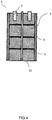
Figure 3 illustrates a reactor segment comprising a support structure in accordance with the present invention. - In
Figure 4 , a reactor segment comprising heaters and a temperature sensor in accordance with the present invention is illustrated. -
Figure 5 illustrates a top view of an active bed comprising heaters and a temperature sensor in accordance with the present invention. - In
Figure 6 , a cartridge in accordance with the present invention is illustrated. - A particular embodiment of the chemical combustion reactor (herein also referred to as reactor), wherein a flow path is provided in the longitudinal direction of the reactor is illustrated in
Figure 1 . The reactor comprises a reactor segment that comprises at least two porous active fixed beds (herein also referred to as simply the active beds) comprising a metal and/or an oxide thereof (herein also referred to as active material) placed in the flow path. Preferably, the chemical combustion reactor and its constituents have a cylindrical shape. The flow path may be used for a gas stream provided through a gas inlet (12) and removed through a gas outlet (13) as depicted inFigure 1 . Preferably, a spacing (17) is provided between the gas inlet and/or outlet and the active bed as illustrated inFigure 1 . This typically allows for an even distribution of the gas before entering the active beds. Alternatively, it may be preferred to provide a gas-distributer within the spacing. The gas-distributor, e.g. a porous plate, typically actively distributes the gas in such a way that it will be evenly distributed before entering the active bed. During operation of the system, the gas stream typically flows through the active beds and can thus come in contact with the active material, thereby generating a reaction front (i.e. the local site where the gas stream reacts with the metal and/or oxide thereof) that moves through the reactor along the longitudinal direction of the reactor. Flow parameters such as the pressure, temperature, concentration of the reducing and oxidizing agent and flow rate of the gas stream may i.a. be tuned to control the charging (reduction reaction) and discharging (oxidation reaction) of the system. Moreover, it may be favorable to tune the flow parameters over the cycles as typically the active bed slightly changes in shape and/or composition after a cycle. - Advantageously, due to the possibility to alter the flow parameters, the reaction front may move at an optimal rate to remain sharp, thin and locally well-defined such that it moves evenly through the reactor within an optimal range of reaction temperatures. Additionally, a more efficient use of the active material in the chemical combustion reactor is allowed.
- Preferably, the reaction front moves through the chemical combustion reactor with a rate in the range of 0.05 to 0.5 mm/s, preferably about 0.2 mm/s. A chemical combustion reactor having a length of 2 meter (which would typically fit in a household environment), being discharged at a rate of 0.2 mm/s would last about 3 hours.
- In a preferred embodiment of the present invention, the reactor segment (3) comprises at least two porous active fixed beds (4) placed in the flow path, wherein said active beds are separated by a porous inactive insulating layer (5), and wherein said insulating mantle (6) at least partially surrounds, preferably directly surrounds, said active beds and said insulating layer in the longitudinal direction of said reactor. It was found that the heat conductivity of the reactor segment in the longitudinal direction of the reactor can be favorably tuned by the insulating layer. The insulating layer can thus provide additional means to ensure a balance between the energy produced in the reaction front and the heat that is transferred in the longitudinal direction of the reactor.
- The terms "active bed" and "inactive insulating layer" (herein also referred to as inactive or insulating layer) relate to their respective reactivity and use when the system is operated. As explained herein, the active bed comprises a metal and/or an oxide thereof that can undergo a redox reaction to store or release heat. Because the active bed can undergo this redox reaction (typically with oxygen-containing or hydrogen-containing gas) at the condition applied during operation of the system, it is referred to as "active" bed. In contrast, at the same condition, the inactive insulating layer, if present, does essentially not undergo a redox reaction. It is essentially inert at these conditions. Depending on the choice of materials, the difference in reactivity between the active bed and the inactive layer can for instance be achieved by basing the inactive layer on a material having a higher oxidation potential (i.e. more noble and thus less prone to oxidation) with respect to that of the active bed. As such, the metal or the oxide thereof in the active bed can selectively be oxidized. In addition, the resulting oxidized product can then be selectively reduced over the inactive layer as well.
- Generally, an activation energy is required to initiate discharging and/or charging. Accordingly, in a preferred embodiment the system further comprises one or more heaters (9) that are thermally connected to at least one active bed. Preferably, the heaters are located in the reactor. This may be at the end of the gas inlet, where the heaters heat up the gas to the extent where enough energy can be provided to initiate the reaction. Alternatively, or additionally, the heaters may be in contact with the active bed as illustrated in
Figure 4 andFigure 5 . The heaters may for instance comprise heating elements that are fully or partially penetrating into the active bed. It is preferred to have the heaters in contact with the active bed, as the reactions typically require a high activation energy and thus high temperatures that may not be provided by a heated gas. The heaters may further be used to reinitiate a reaction after it ceases. - Oxidation and reduction reactions can both either be exothermic or endothermic, depending on the nature of the reactants. Preferably, the oxidation reaction and thus discharging of the reactor is exothermic. The released energy may be used as activation energy for subsequent oxidation reactions. Advantageously, a single initiation of an oxidation reaction may provide a chain of further oxidation reactions without requiring additional energy. In case the reduction reaction is endothermic, a continuous energy supply, such as placing the reactor in an oven, is typically needed for the metal oxide to be reduced in the reactor. Additionally, a continuous energy supply may be necessary for oxidation reactions that are insufficiently exothermic for a subsequent reaction to be initiated. If both the oxidation and reduction reactions are sufficiently exothermic, such energy supply will not be required.
- It is preferred that both reduction and oxidation reactions of the active material are exothermic. More preferably, it is preferred that they are sufficiently exothermic to provide the required activation energy for a subsequent reaction. Advantageously, the reaction can be self-sustainable. However, if too much heat would be transferred to the surroundings, the temperature of the chemical combustion reactor can drop below a critical minimal threshold (i.e. the minimum temperature at which the reaction is self-sustainable) and the discharging and/or charging may cease. However, if too little heat would be transferred, the temperature of the chemical combustion reactor can increase above a critical maximum threshold and the active material may sinter, melt, cluster or otherwise be damaged or displaced. The critical minimal threshold depends i.a. on the type of active material, the type of optional inactive material, the flow speed of reactive gases, and concentration of the reducing or oxidizing agent.
- The active bed comprises a metal and/or oxide thereof (depending on the charge status of the reactor). The metal may be a mixture of a plurality of metals such as separate metals, metal alloys, minerals, or combinations thereof. In any case, the metal is an active metal meaning that it is not inert but can be oxidized with oxygen. Suitable metals comprise one or more metal elements selected from the group consisting of Al, Ti, V, Cr, Mn, Fe, Co, Ni, Cu, Zn, Zr and Sn, preferably Cu, Fe, Ni, Co, or Mn, preferably Cu, Fe, Ni, Co, and/or Mn. More preferably, the metal comprises copper. The metal may be metallic metal, or may be part of a salt or mineral such as ilmenite. Particularly suitable metals and minerals thereof are for instance described in Progress in Chemical-Looping Combustion and Reforming Technologies by Adánez et al., Progress in Energy and Combustion Science 38 (2012) p. 215-282 and in Study of inexpensive oxygen carriers for chemical looping combustion by Fossdal et al., International Journal of Greenhouse Gas Control 5 (2011) p. 483-488.
- Furthermore, the active bed is porous to allow the reaction front to pass through the active bed. In a preferred embodiment, the reactor segment comprises at least two active beds as depicted in
Figures 1 and2 . It is preferred that each bed has an individual porosity between 40-85%, preferably between 50-70%, more preferably between 50-60%, expressed as the percentage void of the total volume occupied by the active bed. The porosity typically provides good access of the gas to the active material, while maintaining optimal use of the space in the reactor to provide a high energy storage density. Moreover, the porosity typically allows the gas to flow through the active bed even when the active material is expanded due to heating. Although each bed may have its individual porosity it is typically preferred when the reactor segment comprises multiple beds that the beds have similar porosities (e.g. between about +/- 10% variation from the porosity of the adjacent or other active beds in the segment or reactor). Advantageously, an evenly distributed reaction front may move continuously through the reactor. Generally, this ensures optimal efficiency. - The active bed is typically built up from structures. The shape of the active bed may be tuned to provide optimal storage density and to provide a self-supporting structure (i.e. it should not compress without additional load present). These structures include, but are not limited to a single wire, multiple wires, wovens, non-wovens, particles, casted structures, mesh, grains, disks, rods, porous carriers such as zeolite having a metal and/or oxide thereof on its surface or in its volume, and combinations or stacks thereof. The structures may further be processed to reach the desired porosity e.g. by compression. The structures may for instance be shaped (e.g. woven) from a single or multiple wires. The diameter of the wires is typically tuned for an optimal balance between storage density and efficiency. Typically, the preferred wire diameter is between 0.05 and 0.3 mm. This dimension is particularly preferred for copper-comprising active beds.
- The single or multiple wires may comprise a single metal and/or oxide thereof, or it may have a core surrounded by a layer of the metal and/or oxide thereof. The layer may for example be sputtered or coated on the core. The core is typically an inert material, or at least does not participate significantly in the redox reactions under the given circumstances. Materials for such cores typically have a high oxidation resistance and high melting temperatures (e.g. above 1000°C). Such materials may include stainless steel, ceramics and/or alloys. Generally, the metal oxide is less physically stable than the metal. More metal may be oxidized (e.g. more than 50%) when using wires comprising a core as the core typically provides stability to minimize compromising the active bed.
- It is moreover possible to add a catalyst to the active bed, this catalyst potentially lowers the reaction temperature or increases the reaction kinetics of the redox reaction taking place with the metal and/or oxide thereof. In general the catalyst may be a noble metal, preferably the catalyst and its respective oxide have a high melting temperature (e.g. above 1000 °C) and low volatility. A preferred catalyst may comprise platinum and/or palladium. The catalyst may be sputtered or coated on the active bed or on the structure before the active bed is formed. Alternatively or additionally, the catalyst may be provided as part of an alloy with the metal. Regardless of the application method, the catalyst and the metal and/or oxide thereof often form an alloy after one or more discharging/ charging cycles.
- As described herein-above, the reactor segment further preferably comprises a porous inactive insulating layer (5) that separates the at least two active beds. The insulating layer typically tunes the heat conductivity of the reactor segment in the longitudinal direction of the reactor. The insulating layer may thus typically ensures a further control over the balance between the energy produced in the reaction front and the heat that is transferred in the longitudinal direction of the reactor. Accordingly, it preferably comprises a material with lower thermal conductivity than the active beds. Materials for the insulating layer typically have a high oxidation resistance and high melting temperatures (e.g. above 1000°C). These materials may for instance include ceramics, alloys, and/or stainless steel. Furthermore, the material may be somewhat rigid as the expansion of the heated active beds is typically minimal in the longitudinal direction of the reactor. Similar to the active beds, the shape of the insulating layer may be tuned to provide optimal insulation and to provide a self-supporting structure (i.e. it should not compress without additional load present). The insulating layer may be formed by one or more structures that include, but are not limited to, a single wire, multiple wires, wovens, non-wovens, particles, casted structures, mesh, grains, disks, rods, porous carriers such as zeolite having a metal and/or oxide thereof on its surface, combinations or stacks thereof. The structures may further be processed to reach the desired porosity e.g. by compression. The structures may for instance be shaped (e.g. woven) from a single or multiple wires.
- A lower thermal conductivity of the optionally present insulating layer typically prevents a too rapid conduction of the heat away from the reaction front. This may be especially beneficial after partial sintering of the active material within the active beds. Advantageously, the lower thermal conductivity may provide efficient use of the active material. It should be noted however, that the insulating layer is preferably not too insulating such that too little heat is transferred within the reactor and the reactions would cease due to hindrance of heating the active material to a temperature higher than the critical minimal temperature required to initiate the reaction to proceed at a sufficiently high speed. The material and its thermal conductivity are typically chosen (e.g. the thickness may be altered) based on the balance between heat produced within a first active bed and heat required for subsequent reactions in a second active bed to occur. Typically, the thermal conductivity of the optional insulating layer is 20 times less than the thermal conductivity of the active bed, allowing the layer to be thin.
- The optional insulating layer is porous to allow the reaction front (i.a. the gas) to move through the insulating layer. Typically, the porous insulating layer has a porosity of up to 90%, preferably between 5-85%, more preferably between 20-70%, most preferably between 40-60%, expressed as the percentage void of the total volume occupied by the insulating layer. For an even continuation of the reaction front it is preferred that the porosity of the insulating layer is similar to the porosity of the active bed (e.g. between about +/- 10% variation from the porosity of the adjacent active bed). It may also be preferred that the reaction front is homogeneously redistributed in the direction perpendicular to the longitudinal direction of the reactor.
- The optional insulating layer typically prevents or at least limits sintering of the active material in those active beds that are separated by sandwiched insulating layer. The layer thus preferably has a higher melting temperature than the active material. Additionally, the material of the insulating layer preferably inhibits sintering with the active material. Advantageously, by reducing sintering of the active material over the entire length of the reactor, the heat generation and heat transfer is well preserved, leading to more efficient use of the active material. In addition, maintenance of the reactor is facilitated if sintering of the active material over the entire length of the reactor is prevented. To further limit sintering of the active material, the active bed and/or insulating layer may comprise an anti-sintering material or catalytic material to lower the activation energy and required temperature. Generally, a small amount or a combination of metals and/or metal oxides such as ZrO2, CaO, Mo and Ce may be sufficient. Additionally, sintering may be limited by choosing a suitable metal and/or an oxide thereof.
- It is preferred that the optional insulating layer is as thin as possible in the longitudinal direction of the reactor. A thinner insulating layer typically enables a higher storage density in the reactor. Dependent on the material the dimensions of the layer may be altered in accordance with the desired thermal conductivity relative to the active material. In particular the ratio between the thickness of the active bed and the thickness of the layer is preferably at least 5:1, more preferably at least 50:1, most preferably at least 100:1.
- The reactor segment further comprises an insulating mantle (herein also simply referred to as mantle) that at least partially, preferably entirely, surrounds the active bed in the longitudinal direction of the reactor. When the reactor segment comprises the optional insulating layer, the mantle at least partially, preferably entirely, surrounds the active bed and the insulating layer in the longitudinal direction of the reactor. The mantle is insulating to advantageously enable the reaction front to continuously flow through the reactor, without excess heat transfer to the adjacent layer e.g. the reactor wall (14) as illustrated in
Figure 1 , or the surroundings. It should be noted that the insulating mantle is preferably not too little insulating such that too much heat is transferred to the surroundings such that the reactions would cease due to limited heating of the active material to a temperature higher than the critical minimal temperature required to initiate the reaction. The reactor may, however, also be used as heat supply when submerged in a tank (16) as illustrated inFigure 1 e.g. an HTF tank as disclosed inWO 2019/050398 , wherein the insulating mantle transfers heat to the HTF via the adjacent layer (e.g. the reactor wall (14)). - The heated active bed may expand in the direction perpendicular to the flow path. Typically, for a cylindrical shaped active bed comprising copper and/or copper oxide the expansion is approximately 2.5% of the diameter of the active bed. While expanding, the active bed may be permanently deformed or the active bed may compress and/or deform the adjacent material. The active bed may contract again to dimensions similar to its initial state after the reaction front has passed due to a decreased temperature. This can leave a gap between the adjacent layer and the active bed, if no suitable counter-measures would be taken. A subsequent gas stream may therefore partially pass through the gap instead of through the active material, reducing efficiency. For this reason, it is preferred that the mantle comprises a compressible material that after compression at least partially decompresses to its initial shape. Compressible may also be interpreted as flexible, malleable, ductile, elastic, formable and the like which all herein at least mean that the mantle material is preferably capable of at least partially reforming back to its initial shape after deformation. More preferably the material reforms completely back to its initial shape.
- To accommodate the expansion and contraction of the active bed by the insulating mantle, it is also preferred that the mantle directly (partially or entirely) surrounds the active bed and optional insulating layer. Directly surrounding herein means that no other layer or structure is placed in between the insulating mantle and the active bed and optional insulating layer assembly. If the active bed does not suffer from expansion and contraction in such an extent that a compressible material is present in the mantle, an additional structure (e.g. an intermediate, rigid wall) may be placed in between the insulating mantle and the active bed and optional insulating layer assembly.
- The mantle material preferably has a higher gas flow resistance than the active bed and the optional insulating layer. The higher resistance typically allows for the gas stream to flow through the active material and optional insulating layer instead of leaking to the mantle. The mantle material may therefore comprise ceramics such as ceramic fibers, ceramic fabrics, open- and/or closed-cell ceramic structures, or inert metal meshes, open- and/or closed-cell foams or combinations thereof.
- The thickness of the insulating mantle typically depends on the desired balance between insulation and heat transfer. Typically, the thickness of the mantle exceeds the maximum expansion of the active bed. The thickness is preferably 1 to 15% of the easy direction of the active bed perpendicular to the longitudinal direction of the reactor. More preferably the thickness is from 2 to 10%, most preferably from 2 to 6%. Easy direction herein relates to the length of the active bed in the direction that expands the furthest when the active bed is heated. For instance, in a cylindrically shaped reactor the easy direction is the diameter of the active bed.
- The reactor segment further preferably comprises a support structure (7) comprising a fixation element (8) as illustrated in
Figure 3 . The support structure supports or carries the active bed, optionally the insulating layer and preferably the insulating mantle as well. The support structure can limit the forces that of the active beds exert on one another and on the optional insulating layer (i.e. the pressure of the load of the higher-placed active bed onto the lower-placed active bed and optional insulating layer). Additional forces may be exerted on the active beds due to a pressure drop over the complete reactor during operation. Limiting the forces can also be achieved by placing the reactor non-vertically, e.g. horizontally (instead of vertically as depicted in the figures), but this will typically face many drawbacks, such as an uneven distribution of condensed water during the reduction phase. The assembly as illustrated inFigure 3 may be stackable in and removable from the reactor as described herein below, and can accordingly be considered a cartridge (11). - The fixation element may be removably fixated to the support structure to simplify placing the constituents (i.a. active beds and optional insulating layer) in the support structure. The fixation element may for example be in the form of a retaining ring for a cylindrical shaped reactor segment. Usually a fixation element is placed on top of the placed constituents and a fixation element is placed below (in the longitudinal direction of the reactor). It may be preferred to secure one or more of the fixation elements to increase the stability.
- An additional aspect of the present invention is directed to the cartridge (11) comprising a reactor segment and a support structure. An example of such cartridge is illustrated in
Figures 3 and6 . The cartridge is preferably adapted to be removable from and stackable within the reactor.Figure 6 , moreover, illustrates the stackable nature of the cartridges within the reactor. Generally, when a defect occurs only a part of the reactor requires replacement. Cartridges allow this replacement in an easy fashion to restore functionality of the reactor. Additionally, it typically allows for full replacement of the content of the reactor in an simple manner. - A gap (15), as depicted in
Figure 6 , can be created when stacking two or more reaction segments comprising a support structure or when stacking two or more cartridges. As such, a linking structure may advantageously be placed to enable a gapless continuation of the reaction front from one reaction segment to a second reaction segment. The linking structure may comprise an additional active bed, or at least it may comprise the same active material. Additionally or alternatively, it may comprise an insulating material (e.g. similar to the material used for the insulating layer). The chosen material may for instance be dependent on the dimensions of the gap. - The system preferably comprises a temperature sensor (10), as illustrated in
Figures 4 and5 , that is preferably located in the chemical combustion reactor such that it can measure a representative temperature of at least one active bed. The sensor is typically used as an indication of the movement of the reaction front. The sensor may comprise a thermocouple with one or more measurement points. Additionally or alternatively, it may comprise temperature fiber optic sensors such as fiber Bragg grating sensors, for example glass fibers. Advantageously, these fibers have a small diameter that may minimize the influence on the performance of the reactor. Furthermore, the glass typically does not interfere significantly with the heat transfer. The temperature sensor may further also be used as a support structure. - The temperature sensor usually measures a representative temperature of at least one active bed. The representative temperature may depend on the shape of the active bed. For a cylindrical active bed, the representative temperature is typically in the center of the active bed.
- The temperature within the reactor may be dependent on the active material used as the temperature typically rises up to the melting temperature of the active material. For instance, when using copper and/or copper oxide the temperature may rise up to 1000°C. Therefore, the temperature sensor should withstand such temperatures and should be capable of measuring these. Moreover, it is typically required that all constituents within the system are able to withstand the obtained temperatures.
- The system may comprise multiple chemical combustion reactors as described herein. Typically, energy for a couple hours is provided from one reactor. A plurality of reactors may thus be used as energy supply for short periods e.g. for households when the renewable energy source is low. In embodiments with the plurality of the chemical combustion reactors, it is preferred that each reactor can be operated (i.e. charged and discharged) independently. This provides additional flexibility to the system and enables for instance simultaneous charging and discharging of the system and energy conversion, which may be desirable during a change of circumstances, such as going from an energy excess to shortage or vice versa.
- Charging of the chemical combustion reactor can be carried out by providing a reducing gas stream, preferably a reducing gas stream comprising methane or hydrogen, and leading the reducing gas stream into the reactor and allowing the reducing gas stream to react with a metal oxide in the reactor to reduce the metal oxide. Accordingly, it may be preferred that the system further comprises a reducing gas supply system. As a preferred reducing gas, hydrogen is used. This gas advantageously typically only produces water upon charging of the reactor. As the temperatures are often sufficiently high for the water to be gaseous, it may be preferred that the system further comprises a condenser to liquefy the water. Moreover, it may be preferred to use the water as a source for subsequent gas streams.
- Discharging of the chemical combustion reactor can be carried out by providing an oxidizing gas stream, preferably an oxidizing gas stream comprising oxygen, and leading the oxidizing gas stream into the reactor and allowing the oxidizing gas stream to react with the metal to oxidize the metal. Accordingly, it may be preferred that the system further comprises an oxidizing gas supply system.
- Generally, a single inlet and a single gas outlet for the chemical combustion reactor is preferred, as this improves the reliability and decreases the chance of system failures. The inlet and outlet of the reactor can be used as such for both the reduction and the oxidation gas streams, such that the reactor is discharged and charged with gas streams flowing in the same direction. However, the direction in which the reactor is charged may also be reverse of the direction in which the reactor is discharged. In such embodiment, the inlet and outlet may thus switch their function: the inlet becomes the outlet and vice versa.
- Further aspects of the present invention are directed to methods for charging and discharging the system. A particular method for storing energy in a system in accordance with the present invention comprises providing a reducing gas stream, preferably a reducing gas stream comprising hydrogen gas, and leading said reducing gas stream into the chemical combustion reactor and allowing the reducing gas stream to react with a metal oxide in the chemical combustion reactor to reduce the metal.
- A particular method for discharging energy from a system in accordance with the present invention comprises providing an oxidizing gas stream, preferably an oxidizing gas stream comprising oxygen gas, and leading said oxidizing gas stream into the reactor and allowing the oxidizing gas stream to react with a metal in the reactor to oxidize the metal.
- For the purpose of clarity and a concise description features are described herein as part of the same or separate embodiments, however, it will be appreciated that the scope of the invention may include embodiments having combinations of all or some of the features described.
- The project leading to this application has received funding from the European Unions' Horizon 2020 research and innovation programme under grant agreement No
766464
Claims (15)
- A system for energy storage comprising a chemical combustion reactor (1) wherein a flow path (2) is provided in a longitudinal direction of said reactor, said reactor comprising a reactor segment (3) that comprises at least one porous active fixed bed (4) comprising a metal and/or oxide thereof that is at least partially surrounded by an insulating mantle (6) in the longitudinal direction of said reactor.
- A system according to the previous claim, wherein said reactor segment (3) comprises at least two porous active fixed beds (4) placed in the flow path, wherein said active beds are separated by a porous inactive insulating layer (5), and wherein said insulating mantle (6) at least partially surrounds, preferably directly surrounds, said active beds and said insulating layer in the longitudinal direction of said reactor.
- System according to any of the previous claims, wherein said segment comprises a support structure (7), wherein said support structure comprises a fixation element (8) that is adapted for supporting at least said active bed and optionally said insulating layer in the chemical combustion reactor.
- System according to any of the previous claims further comprising one or more heaters (9), preferably located in the chemical combustion reactor such that they are thermally connected to at least one active bed, more preferably wherein said one or more heaters comprise a heating element penetrating the active bed it is thermally connected to.
- System according to any of the previous claims further comprising a temperature sensor (10), preferably located in the chemical combustion reactor and adapted to measure a representative temperature of at least one active bed, more preferably wherein said temperature sensor comprises a sensor element penetrating the active bed, typically the center of the active bed, for which it is adapted to measure the temperature thereof.
- System according to any of the previous claims wherein both reduction and oxidation reaction of said metal and/or oxide thereof are exothermic.
- System according to any of the previous claims wherein said metal and/or oxide thereof comprises a metal element selected from the group consisting of Al, Ti, V, Cr, Mn, Fe, Co, Ni, Cu, Zn, Zr, Sn and combinations thereof, preferably Cu, Fe, Ni, Co and Mn, more preferably copper.
- System according to any of the previous claims wherein said active beds further comprise a catalyst, preferably platinum and/or palladium.
- System according to any of the previous claims wherein said active beds individually have a porosity between 40-85%, preferably between 50-70%, more preferably between 50-60%, expressed as the percentage void based on the total volume occupied by the active bed.
- System according to any of the previous claims 2-9, wherein said porous insulating layer comprises an inactive material with lower thermal conductivity than said metal and/or oxide thereof, wherein said inactive material preferably comprises stainless steel.
- System according to any of the previous claims 2-10, wherein said porous insulating layer has a porosity of up to 90%, preferably between 5-85%, more preferably between 20-70%, most preferably between 40-60%, expressed as the percentage void of the total volume occupied by the insulating layer.
- System according to any of the previous claims, wherein said insulating mantle comprises a compressible material that after compression at least partially decompresses to its initial shape, preferably completely decompresses to its initial shape, and wherein said insulating mantle has a higher gas-flow resistance than each of said active beds.
- A cartridge (11) comprising a segment as defined in any of claims 3-12, and a support structure for supporting said segment, wherein said cartridge is adapted to be removable from and stackable within the reactor according to any of the previous claims.
- Method for storing energy in a system according to any of claims 1-12, said method comprising providing a reducing gas stream, preferably a reducing gas stream comprising hydrogen gas, and leading said reducing gas stream into the chemical combustion reactor and allowing the reducing gas stream to react with a metal oxide in the chemical combustion reactor to reduce the metal oxide.
- Method for discharging energy from a system according to any of claims 1-12, said method comprising providing an oxidizing gas stream, preferably an oxidizing gas stream comprising oxygen gas, and leading said oxidizing gas stream into the chemical combustion reactor and allowing the oxidizing gas stream to react with a metal in the chemical combustion reactor to oxidize the metal.
Priority Applications (4)
| Application Number | Priority Date | Filing Date | Title |
|---|---|---|---|
| EP20164249.3A EP3882554A1 (en) | 2020-03-19 | 2020-03-19 | Internal configuration for redox-based heat storage systems |
| EP21714276.9A EP4121709B1 (en) | 2020-03-19 | 2021-03-19 | Internal configuration for redox-based heat storage systems |
| PCT/NL2021/050188 WO2021187987A1 (en) | 2020-03-19 | 2021-03-19 | Internal configuration for redox-based heat storage systems |
| US17/906,306 US12298084B2 (en) | 2020-03-19 | 2021-03-19 | Internal configuration for redox-based heat storage systems |
Applications Claiming Priority (1)
| Application Number | Priority Date | Filing Date | Title |
|---|---|---|---|
| EP20164249.3A EP3882554A1 (en) | 2020-03-19 | 2020-03-19 | Internal configuration for redox-based heat storage systems |
Publications (1)
| Publication Number | Publication Date |
|---|---|
| EP3882554A1 true EP3882554A1 (en) | 2021-09-22 |
Family
ID=69846351
Family Applications (2)
| Application Number | Title | Priority Date | Filing Date |
|---|---|---|---|
| EP20164249.3A Withdrawn EP3882554A1 (en) | 2020-03-19 | 2020-03-19 | Internal configuration for redox-based heat storage systems |
| EP21714276.9A Active EP4121709B1 (en) | 2020-03-19 | 2021-03-19 | Internal configuration for redox-based heat storage systems |
Family Applications After (1)
| Application Number | Title | Priority Date | Filing Date |
|---|---|---|---|
| EP21714276.9A Active EP4121709B1 (en) | 2020-03-19 | 2021-03-19 | Internal configuration for redox-based heat storage systems |
Country Status (3)
| Country | Link |
|---|---|
| US (1) | US12298084B2 (en) |
| EP (2) | EP3882554A1 (en) |
| WO (1) | WO2021187987A1 (en) |
Families Citing this family (1)
| Publication number | Priority date | Publication date | Assignee | Title |
|---|---|---|---|---|
| CN118463687B (en) * | 2024-06-04 | 2024-11-12 | 江苏瑞鼎环境工程有限公司 | A cold storage system and process for waste heat of flue gas in low temperature section of incinerator |
Citations (9)
| Publication number | Priority date | Publication date | Assignee | Title |
|---|---|---|---|---|
| JPS6152550A (en) * | 1984-08-21 | 1986-03-15 | Hitachi Chem Co Ltd | Hot water supplying system utilizing chemical heat storage |
| JPS62288495A (en) * | 1986-06-03 | 1987-12-15 | Sumitomo Metal Ind Ltd | Heat exchanger |
| WO2006123925A1 (en) | 2005-05-18 | 2006-11-23 | Nederlandse Organisatie Voor Toegepast-Natuurwetenschappelijk Onderzoek Tno | Method for regulating the heat and the co2 concentration of the air in an enclosed space |
| WO2012144896A1 (en) | 2011-04-21 | 2012-10-26 | Nederlandse Organisatie Voor Toegepast-Natuurwetenschappelijk Onderzoek Tno | Fixed bed chemical looping combustion |
| EP3006883A1 (en) * | 2013-07-12 | 2016-04-13 | Aisin Seiki Kabushiki Kaisha | Chemical thermal energy storage device |
| US20180180325A1 (en) * | 2015-06-26 | 2018-06-28 | The Regents Of The University Of California | High temperature synthesis for power production and storage |
| EP3396289A1 (en) * | 2015-12-24 | 2018-10-31 | Kabushiki Kaisha Toyota Jidoshokki | Chemical heat storage apparatus |
| WO2019050397A1 (en) | 2017-09-06 | 2019-03-14 | Nederlandse Organisatie Voor Toegepastnatuurwetenschappelijk Onderzoek Tno | System for energy storage including heat exchangers |
| WO2019050398A1 (en) | 2017-09-06 | 2019-03-14 | Nederlandse Organisatie Voor Teogepastnatuurwetenschappelijk Onderzoek Tno | System for energy storage including a heat transfer fluid tank |
Family Cites Families (27)
| Publication number | Priority date | Publication date | Assignee | Title |
|---|---|---|---|---|
| US4034569A (en) * | 1974-11-04 | 1977-07-12 | Tchernev Dimiter I | Sorption system for low-grade (solar) heat utilization |
| US4161211A (en) * | 1975-06-30 | 1979-07-17 | International Harvester Company | Methods of and apparatus for energy storage and utilization |
| DE2717101C2 (en) * | 1977-04-18 | 1986-04-03 | Didier Engineering Gmbh, 4300 Essen | Process for the catalytic conversion of a reducing gas |
| US4470931A (en) * | 1978-10-24 | 1984-09-11 | The Standard Oil Company | Combination fixed-fluid bed reactor |
| US4341262A (en) * | 1980-05-05 | 1982-07-27 | Alspaugh Thomas R | Energy storage system and method |
| US4424397A (en) * | 1982-09-27 | 1984-01-03 | E. I. Du Pont De Nemours And Company | Formaldehyde process |
| US4928496A (en) * | 1989-04-14 | 1990-05-29 | Advanced Materials Corporation | Hydrogen heat pump |
| CA2171279C (en) * | 1996-03-07 | 2007-09-18 | Richard Auger | Reactor for treating a liquid |
| US6117812A (en) * | 1998-10-06 | 2000-09-12 | China Petro-Chemical Corporation | Dual functional catalyst of packing type and the catalytic distillation equipment |
| US6478077B1 (en) * | 2001-05-15 | 2002-11-12 | Sandia National Laboratories | Self supporting heat transfer element |
| US7393510B2 (en) * | 2003-03-25 | 2008-07-01 | Crystaphase International, Inc. | Decontamination of process streams |
| JP4167607B2 (en) * | 2004-02-27 | 2008-10-15 | 株式会社豊田自動織機 | Hydrogen storage tank |
| DE102006010636A1 (en) * | 2005-12-19 | 2007-06-21 | BLüCHER GMBH | Sorption storage unit for gases |
| DE102007026712A1 (en) * | 2007-06-06 | 2008-12-11 | Uhde Gmbh | Apparatus and method for catalytic gas phase reactions and their use |
| WO2010091178A1 (en) * | 2009-02-04 | 2010-08-12 | Purdue Research Foundation | Coiled and microchannel heat exchangers for metal hydride storage systems |
| US8636836B2 (en) * | 2009-02-04 | 2014-01-28 | Purdue Research Foundation | Finned heat exchangers for metal hydride storage systems |
| GB0918246D0 (en) * | 2009-10-19 | 2009-12-02 | Davy Process Techn Ltd | Apparatus |
| JP6099299B2 (en) * | 2010-07-06 | 2017-03-22 | 株式会社ルネッサンス・エナジー・リサーチ | Carbon monoxide conversion apparatus and method, and hydrogen production apparatus |
| JP5698056B2 (en) * | 2011-03-31 | 2015-04-08 | 株式会社豊田中央研究所 | Chemical heat storage device |
| US10054140B2 (en) * | 2016-02-12 | 2018-08-21 | Crystaphase Products, Inc. | Use of treating elements to facilitate flow in vessels |
| JP6868393B2 (en) * | 2016-12-28 | 2021-05-12 | 日本ペイントホールディングス株式会社 | Storage and heat dissipation device |
| US10329225B2 (en) * | 2017-01-20 | 2019-06-25 | Saudi Arabian Oil Company | Dual catalyst processes and systems for propylene production |
| EP3382314A1 (en) * | 2017-03-30 | 2018-10-03 | Nederlandse Organisatie voor toegepast- natuurwetenschappelijk onderzoek TNO | Enhanced tcm production and use |
| AU2018386998B2 (en) * | 2017-12-21 | 2023-03-30 | Casale Sa | Multi-bed catalytic converter |
| KR102142355B1 (en) * | 2018-11-23 | 2020-08-07 | 한국화학연구원 | Cdr reactor for preventing catalyst inactivation having multi-layered catalyst |
| CN113557617B (en) * | 2019-01-07 | 2024-10-29 | 密歇根州立大学董事会 | Thermochemical renewable energy storage systems and operations |
| US20230266074A1 (en) * | 2022-02-20 | 2023-08-24 | Molecule Works Inc. | Device for mass and/or heat transfer and process for capturing a molecule in a process fluid using the device |
-
2020
- 2020-03-19 EP EP20164249.3A patent/EP3882554A1/en not_active Withdrawn
-
2021
- 2021-03-19 WO PCT/NL2021/050188 patent/WO2021187987A1/en not_active Ceased
- 2021-03-19 EP EP21714276.9A patent/EP4121709B1/en active Active
- 2021-03-19 US US17/906,306 patent/US12298084B2/en active Active
Patent Citations (9)
| Publication number | Priority date | Publication date | Assignee | Title |
|---|---|---|---|---|
| JPS6152550A (en) * | 1984-08-21 | 1986-03-15 | Hitachi Chem Co Ltd | Hot water supplying system utilizing chemical heat storage |
| JPS62288495A (en) * | 1986-06-03 | 1987-12-15 | Sumitomo Metal Ind Ltd | Heat exchanger |
| WO2006123925A1 (en) | 2005-05-18 | 2006-11-23 | Nederlandse Organisatie Voor Toegepast-Natuurwetenschappelijk Onderzoek Tno | Method for regulating the heat and the co2 concentration of the air in an enclosed space |
| WO2012144896A1 (en) | 2011-04-21 | 2012-10-26 | Nederlandse Organisatie Voor Toegepast-Natuurwetenschappelijk Onderzoek Tno | Fixed bed chemical looping combustion |
| EP3006883A1 (en) * | 2013-07-12 | 2016-04-13 | Aisin Seiki Kabushiki Kaisha | Chemical thermal energy storage device |
| US20180180325A1 (en) * | 2015-06-26 | 2018-06-28 | The Regents Of The University Of California | High temperature synthesis for power production and storage |
| EP3396289A1 (en) * | 2015-12-24 | 2018-10-31 | Kabushiki Kaisha Toyota Jidoshokki | Chemical heat storage apparatus |
| WO2019050397A1 (en) | 2017-09-06 | 2019-03-14 | Nederlandse Organisatie Voor Toegepastnatuurwetenschappelijk Onderzoek Tno | System for energy storage including heat exchangers |
| WO2019050398A1 (en) | 2017-09-06 | 2019-03-14 | Nederlandse Organisatie Voor Teogepastnatuurwetenschappelijk Onderzoek Tno | System for energy storage including a heat transfer fluid tank |
Non-Patent Citations (3)
| Title |
|---|
| ADANEZ ET AL.: "Progress in Chemical-Looping Combustion and Reforming Technologies", PROGRESS IN ENERGY AND COMBUSTION SCIENCE, vol. 38, 2012, pages 215 - 282, XP055022410, DOI: 10.1016/j.pecs.2011.09.001 |
| FOSSDAL ET AL.: "Study of inexpensive oxygen carriers for chemical looping combustion", INTERNATIONAL JOURNAL OF GREENHOUSE GAS CONTROL, vol. 5, 2011, pages 483 - 488, XP055022389, DOI: 10.1016/j.ijggc.2010.08.001 |
| HOSSAIN ET AL., CHEMICAL ENGINEERING SCIENCE, vol. 63, 2008, pages 4433 - 4451 |
Also Published As
| Publication number | Publication date |
|---|---|
| WO2021187987A1 (en) | 2021-09-23 |
| EP4121709B1 (en) | 2025-05-07 |
| EP4121709A1 (en) | 2023-01-25 |
| US20230139510A1 (en) | 2023-05-04 |
| US12298084B2 (en) | 2025-05-13 |
Similar Documents
| Publication | Publication Date | Title |
|---|---|---|
| US12123655B2 (en) | Thermochemical renewable energy storage | |
| US20150129805A1 (en) | Method for producing co and/or h2 in an alternating operation between two operating modes | |
| CN100367556C (en) | Thermally enhanced small reformer | |
| US6972119B2 (en) | Apparatus for forming hydrogen | |
| AU2010253491B2 (en) | Gas generator and processes for the conversion of a fuel into an oxygen-depleted gas and/or hydrogen-enriched gas | |
| Dittmeyer et al. | Micro and micro membrane reactors for advanced applications in chemical energy conversion | |
| EP1273552A2 (en) | Hydrogen producing apparatus and power generating system | |
| US20020114747A1 (en) | Fuel processing system and apparatus therefor | |
| EP1636132A1 (en) | Method for producing electricity using temperature swing reforming and solid oxide fuel cell | |
| US20200173734A1 (en) | System for energy storage including a heat transfer fluid tank | |
| EP4121709B1 (en) | Internal configuration for redox-based heat storage systems | |
| WO2019050397A1 (en) | System for energy storage including heat exchangers | |
| JP3473896B2 (en) | Hydrogen purification equipment | |
| EP1329417A1 (en) | Hydrogen forming device | |
| US20210284540A1 (en) | Facile co2 sequestration and fuel production from a hydrocarbon | |
| CN100540459C (en) | Method for generating electricity using temperature swing reforming and solid oxide fuel cells | |
| JP4848294B2 (en) | Hydrogen production catalyst for fuel cell and fuel cell for DSS operation | |
| JP2004043218A (en) | Fuel reformer and its operation method | |
| WO2003035546A1 (en) | Method and apparatus for steam reforming | |
| WO2004086585A2 (en) | Sorfc system and method with an exothermic net electrolysis reaction | |
| EP2006945A1 (en) | Method for starting up a fuel cell assembly | |
| JP2006008434A (en) | Hydrogen generator, fuel cell power generation system, and hydrogen generation method | |
| Lukyanov | Catalytic production of hydrogen from methanol for mobile, stationary and portable fuel-cell power plants | |
| EP2869381A1 (en) | An integrated catalytic steam reforming fuel cell electrode | |
| Yoshida | Development of hydrogen absorption/desorption tank using waste heat with hydrogen as a heat transfer medium and design of integrated system with fuel cells |
Legal Events
| Date | Code | Title | Description |
|---|---|---|---|
| PUAI | Public reference made under article 153(3) epc to a published international application that has entered the european phase |
Free format text: ORIGINAL CODE: 0009012 |
|
| STAA | Information on the status of an ep patent application or granted ep patent |
Free format text: STATUS: THE APPLICATION HAS BEEN PUBLISHED |
|
| AK | Designated contracting states |
Kind code of ref document: A1 Designated state(s): AL AT BE BG CH CY CZ DE DK EE ES FI FR GB GR HR HU IE IS IT LI LT LU LV MC MK MT NL NO PL PT RO RS SE SI SK SM TR |
|
| STAA | Information on the status of an ep patent application or granted ep patent |
Free format text: STATUS: THE APPLICATION IS DEEMED TO BE WITHDRAWN |
|
| 18D | Application deemed to be withdrawn |
Effective date: 20220323 |