EP3882512A1 - Fan lamp - Google Patents
Fan lamp Download PDFInfo
- Publication number
- EP3882512A1 EP3882512A1 EP19905171.5A EP19905171A EP3882512A1 EP 3882512 A1 EP3882512 A1 EP 3882512A1 EP 19905171 A EP19905171 A EP 19905171A EP 3882512 A1 EP3882512 A1 EP 3882512A1
- Authority
- EP
- European Patent Office
- Prior art keywords
- fan
- light source
- setting area
- groove
- source setting
- Prior art date
- Legal status (The legal status is an assumption and is not a legal conclusion. Google has not performed a legal analysis and makes no representation as to the accuracy of the status listed.)
- Granted
Links
Images


Classifications
-
- F—MECHANICAL ENGINEERING; LIGHTING; HEATING; WEAPONS; BLASTING
- F04—POSITIVE - DISPLACEMENT MACHINES FOR LIQUIDS; PUMPS FOR LIQUIDS OR ELASTIC FLUIDS
- F04D—NON-POSITIVE-DISPLACEMENT PUMPS
- F04D25/00—Pumping installations or systems
- F04D25/02—Units comprising pumps and their driving means
- F04D25/08—Units comprising pumps and their driving means the working fluid being air, e.g. for ventilation
- F04D25/088—Ceiling fans
-
- F—MECHANICAL ENGINEERING; LIGHTING; HEATING; WEAPONS; BLASTING
- F04—POSITIVE - DISPLACEMENT MACHINES FOR LIQUIDS; PUMPS FOR LIQUIDS OR ELASTIC FLUIDS
- F04D—NON-POSITIVE-DISPLACEMENT PUMPS
- F04D19/00—Axial-flow pumps
- F04D19/002—Axial flow fans
-
- F—MECHANICAL ENGINEERING; LIGHTING; HEATING; WEAPONS; BLASTING
- F04—POSITIVE - DISPLACEMENT MACHINES FOR LIQUIDS; PUMPS FOR LIQUIDS OR ELASTIC FLUIDS
- F04D—NON-POSITIVE-DISPLACEMENT PUMPS
- F04D29/00—Details, component parts, or accessories
- F04D29/005—Decorative aspects, i.e. features which have no effect on the functioning of the pump
-
- F—MECHANICAL ENGINEERING; LIGHTING; HEATING; WEAPONS; BLASTING
- F04—POSITIVE - DISPLACEMENT MACHINES FOR LIQUIDS; PUMPS FOR LIQUIDS OR ELASTIC FLUIDS
- F04D—NON-POSITIVE-DISPLACEMENT PUMPS
- F04D29/00—Details, component parts, or accessories
- F04D29/60—Mounting; Assembling; Disassembling
- F04D29/64—Mounting; Assembling; Disassembling of axial pumps
- F04D29/644—Mounting; Assembling; Disassembling of axial pumps especially adapted for elastic fluid pumps
- F04D29/646—Mounting or removal of fans
-
- F—MECHANICAL ENGINEERING; LIGHTING; HEATING; WEAPONS; BLASTING
- F21—LIGHTING
- F21S—NON-PORTABLE LIGHTING DEVICES; SYSTEMS THEREOF; VEHICLE LIGHTING DEVICES SPECIALLY ADAPTED FOR VEHICLE EXTERIORS
- F21S8/00—Lighting devices intended for fixed installation
- F21S8/04—Lighting devices intended for fixed installation intended only for mounting on a ceiling or the like overhead structures
-
- F—MECHANICAL ENGINEERING; LIGHTING; HEATING; WEAPONS; BLASTING
- F21—LIGHTING
- F21V—FUNCTIONAL FEATURES OR DETAILS OF LIGHTING DEVICES OR SYSTEMS THEREOF; STRUCTURAL COMBINATIONS OF LIGHTING DEVICES WITH OTHER ARTICLES, NOT OTHERWISE PROVIDED FOR
- F21V3/00—Globes; Bowls; Cover glasses
-
- F—MECHANICAL ENGINEERING; LIGHTING; HEATING; WEAPONS; BLASTING
- F21—LIGHTING
- F21V—FUNCTIONAL FEATURES OR DETAILS OF LIGHTING DEVICES OR SYSTEMS THEREOF; STRUCTURAL COMBINATIONS OF LIGHTING DEVICES WITH OTHER ARTICLES, NOT OTHERWISE PROVIDED FOR
- F21V33/00—Structural combinations of lighting devices with other articles, not otherwise provided for
- F21V33/0088—Ventilating systems
- F21V33/0096—Fans, e.g. ceiling fans
-
- F—MECHANICAL ENGINEERING; LIGHTING; HEATING; WEAPONS; BLASTING
- F04—POSITIVE - DISPLACEMENT MACHINES FOR LIQUIDS; PUMPS FOR LIQUIDS OR ELASTIC FLUIDS
- F04D—NON-POSITIVE-DISPLACEMENT PUMPS
- F04D25/00—Pumping installations or systems
- F04D25/16—Combinations of two or more pumps ; Producing two or more separate gas flows
- F04D25/166—Combinations of two or more pumps ; Producing two or more separate gas flows using fans
-
- F—MECHANICAL ENGINEERING; LIGHTING; HEATING; WEAPONS; BLASTING
- F21—LIGHTING
- F21V—FUNCTIONAL FEATURES OR DETAILS OF LIGHTING DEVICES OR SYSTEMS THEREOF; STRUCTURAL COMBINATIONS OF LIGHTING DEVICES WITH OTHER ARTICLES, NOT OTHERWISE PROVIDED FOR
- F21V29/00—Protecting lighting devices from thermal damage; Cooling or heating arrangements specially adapted for lighting devices or systems
- F21V29/50—Cooling arrangements
- F21V29/60—Cooling arrangements characterised by the use of a forced flow of gas, e.g. air
- F21V29/67—Cooling arrangements characterised by the use of a forced flow of gas, e.g. air characterised by the arrangement of fans
- F21V29/677—Cooling arrangements characterised by the use of a forced flow of gas, e.g. air characterised by the arrangement of fans the fans being used for discharging
-
- F—MECHANICAL ENGINEERING; LIGHTING; HEATING; WEAPONS; BLASTING
- F21—LIGHTING
- F21V—FUNCTIONAL FEATURES OR DETAILS OF LIGHTING DEVICES OR SYSTEMS THEREOF; STRUCTURAL COMBINATIONS OF LIGHTING DEVICES WITH OTHER ARTICLES, NOT OTHERWISE PROVIDED FOR
- F21V29/00—Protecting lighting devices from thermal damage; Cooling or heating arrangements specially adapted for lighting devices or systems
- F21V29/50—Cooling arrangements
- F21V29/70—Cooling arrangements characterised by passive heat-dissipating elements, e.g. heat-sinks
- F21V29/83—Cooling arrangements characterised by passive heat-dissipating elements, e.g. heat-sinks the elements having apertures, ducts or channels, e.g. heat radiation holes
-
- F—MECHANICAL ENGINEERING; LIGHTING; HEATING; WEAPONS; BLASTING
- F21—LIGHTING
- F21V—FUNCTIONAL FEATURES OR DETAILS OF LIGHTING DEVICES OR SYSTEMS THEREOF; STRUCTURAL COMBINATIONS OF LIGHTING DEVICES WITH OTHER ARTICLES, NOT OTHERWISE PROVIDED FOR
- F21V3/00—Globes; Bowls; Cover glasses
- F21V3/02—Globes; Bowls; Cover glasses characterised by the shape
-
- F—MECHANICAL ENGINEERING; LIGHTING; HEATING; WEAPONS; BLASTING
- F21—LIGHTING
- F21Y—INDEXING SCHEME ASSOCIATED WITH SUBCLASSES F21K, F21L, F21S and F21V, RELATING TO THE FORM OR THE KIND OF THE LIGHT SOURCES OR OF THE COLOUR OF THE LIGHT EMITTED
- F21Y2105/00—Planar light sources
- F21Y2105/10—Planar light sources comprising a two-dimensional [2D] array of point-like light-generating elements
- F21Y2105/14—Planar light sources comprising a two-dimensional [2D] array of point-like light-generating elements characterised by the overall shape of the two-dimensional [2D] array
- F21Y2105/18—Planar light sources comprising a two-dimensional [2D] array of point-like light-generating elements characterised by the overall shape of the two-dimensional [2D] array annular; polygonal other than square or rectangular, e.g. for spotlights or for generating an axially symmetrical light beam
Definitions
- the present disclosure relates to the technical field of electric appliances, and particularly relates to a fan lamp.
- the lamp is an essential lighting electric appliance in people's life and can provide lighting light for the indoor space at night.
- the ceiling fan is also a cooling electric appliance which is used for a long time and can be used for cooling in hot summer.
- the lamp and the ceiling fan need to be arranged on a ceiling, and the working areas of the lamp and the ceiling fan are areas where people often move, so that the arrangement positions conflict.
- a solution of combining the ceiling fan and the lamp has been provided in the related technology.
- a motor and fan blades of the ceiling fan are generally integrated on a ceiling lamp to form a fan ceiling lamp, and the fan ceiling lamp can be used for lighting and can also supply air.
- the ceiling lamp is a decorative lamp deviated from European style, and the ceiling lamp occupies a large floor height, so that the ceiling lamp is only suitable for being installed in a building with a high floor height, and is not suitable for being installed in a common house with the floor height of 2.8m.
- the motor and the fan blades are further integrated on the basis of the ceiling lamp, so that the floor height occupied by the ceiling lamp is larger, and the ceiling lamp can affect the attractiveness and cause a sense of repression and can also cause potential safety hazards when installed in the common house.
- Embodiments of the present application provide a fan lamp, to solve the above-mentioned problems.
- An embodiment of the present disclosure provides a fan lamp, which includes a base, a first light source module and a fan;
- the base further includes a power supply cavity, the power supply cavity protrudes out of the first side, the fan groove is arranged around the power supply cavity, and the power supply cavity exceeds a groove of the fan groove.
- a plurality of fans are provided, and the fan groove is divided into a plurality of independent fan sub-grooves, each of the plurality of fan sub-grooves is provided with one of the plurality of fans, and the air outlet duct extends to each of the plurality of fan sub-grooves.
- the plurality of fan sub-grooves are arranged along a circumferential direction.
- a separation blade is arranged in the fan groove, and two adjacent ones of the plurality of fan sub-grooves are separated by the separation blade.
- the fan is a turbofan
- the turbofan is sleeved around the power supply cavity.
- a plurality of air deflectors are uniformly distributed in the air outlet duct along a circumferential direction, and all of the plurality of air deflectors are obliquely arranged relative to the opening along a same clockwise direction.
- the fan lamp further includes a second light source module, a second light source setting area is further arranged at the second side, the second light source setting area surrounds the opening, and the second light source module is arranged in the second light source setting area.
- a fairing ring is formed between the first light source setting area and the second light source setting area and is positioned in front of the opening.
- the fan lamp further includes a first light-transmitting cover and a second light-transmitting cover, the first light-transmitting cover is matched with the first light source setting area in shape and covers the first light source setting area, and the second light-transmitting cover is matched with the second light source setting area in shape and covers the second light source setting area.
- the fan lamp further includes a back cover, the back cover is matched with the fan groove in shape and covers the fan groove, and the back cover is provided with an air inlet at a position corresponding to the fan.
- a plurality of partition strips are arranged at a side, away from the fan groove, of the back cover at intervals, and a part of the plurality of partition strips extends across the air inlet.
- the fan is arranged in the fan groove to form a pressurization effect to supply air, so that the height of the fan lamp is close to that of the ceiling lamp, and the occupied space in floor height and potential safety hazards are greatly reduced.
- the fan lamp includes a base 1, a first light source module (not shown in the figure) and a fan 2.
- the base 1 is a main body structure of the fan lamp and plays a role in fixing and protecting other components.
- the base 1 includes a first side and a second side (not marked in the figure) which are away from each other, the first side includes a fan groove 10, and a first light source setting area 11 (see Fig. 3 ) is arranged at the second side; and meanwhile, an air outlet duct 12 is further arranged on the base 1 and communicated with the fan groove 10 and the second side, and an opening 120, at the second side, of the air outlet duct 12 surrounds the first light source setting area 11.
- the light source module is arranged in the first light source setting area 11, and the fan 2 is arranged in the fan groove 10. Because the fan 2 in the present embodiment is arranged in the fan groove 10, other directions, except the air inlet side, of the fan 2 are relatively closed, the fan can achieve the pressurization effect through such structure, the air inlet amount and the air outlet amount are increased, and therefore no too much distance needs to be reserved between the fan 2 and a ceiling in the embodiment, the overall floor height occupied by the fan lamp can be greatly reduced, the fan lamp is closer to the ceiling and is located at the position where people cannot touch the fan lamp easily, and the repression feeling brought by the lamp is effectively reduced. In addition, because the fan lamp is located at the position where people cannot touch the fan lamp easily, the fan 2 is arranged in the fan groove 10, no blade stretches out in the working state, so that the safety coefficient is higher.
- the fan lamp generally includes a drive module (not shown in the figure), and in order to arrange the drive module, the base 1 further includes a power supply cavity 13.
- the power supply cavity 13 is defined by a solid structure and protrudes out of the first side.
- the opening of the power supply cavity 13 is arranged at the second side, and a main body part extends and protrudes from the second side to the first side.
- the power supply cavity 13 is formed by adopting an outer cover to cover the first side, and the two structures can be selected according to needs.
- the fan groove 10 can be arranged around the power supply cavity 13 in order to ensure uniform air outlet. Because the fan 2 needs to be fed with air from the opening of the fan groove 10, a groove of the fan groove 10 cannot be clung to the ceiling upon the fan lamp being installed.
- the power supply cavity 13 in the embodiment can exceed the groove of the fan groove 10, so that enough gap for air feeding can be reserved between the groove of the fan groove 10 and the ceiling due to the obstruction of the power supply cavity 13 upon the fan lamp being installed.
- one fan 2 can be adopted, and a plurality of fans 2 can also be adopted simultaneously.
- the fan 2 is a turbofan, and the turbofan is sleeved around the power supply cavity 13 during installing.
- the fans 2 can be simultaneously arranged in the fan groove 10, but because different fans 2 can generate different air flows, in order to prevent the adjacent fans from interfering with each other, the fan groove 10 is divided into a plurality of independent fan sub-grooves 100, each of the plurality of fan sub-grooves 100 is provided with one of the plurality of fans 2, and the air outlet duct 12 extends to each of the plurality of fan sub-grooves 100 simultaneously.
- the fan sub-grooves 100 have a plurality of arrangement modes which are mainly designed according to the size of the fan 2 and the structure of the air outlet duct 12.
- the fan sub-grooves 100 are preferably arranged along the circumferential direction, and the fan sub-grooves 100 can form a fan-shaped structure, a conch-shaped structure or other structures.
- the air outlet duct 12 is positioned in the outer side area of the fan-shaped structure, thereby forming a larger air outlet ring.
- Two adjacent fan sub-grooves 100 can be separated by a separation blade 102 or other parts, the separation blade 102 can be integrally arranged with the fan groove 10, so that the separation blade is recommended to be adopted.
- a plurality of air deflectors 122 are uniformly distributed in the air outlet duct 12 along the circumferential direction
- the air deflectors 122 can be integrally arranged with the air outlet duct 12 and can also be independently arranged in the form of air guide grooves, and all the air deflectors 122 are obliquely arranged relative to the opening 120 along the same clockwise direction (such as clockwise or anticlockwise). Therefore, the air blown by all the fans 2 can form vortex-shaped disturbance air, the flowing effect of the air can be improved, and the air volume can be increased.
- each fan 2 can be independently matched with different rotating speeds through a driving module, so that the air volume is locally adjusted, the superposition effect is changed, and more air outlet modes are realized.
- the fan lamp in the embodiment can further include a second light source module (not shown in the figure), a second light source setting area 14 is further arranged at the second side, the second light source setting area 14 surrounds the opening 120, and the second light source module is arranged in the second light source setting area 14.
- the second light source module can be a light-emitting device with different power or colors from the first light source module.
- the second light source module can be a low-power light-emitting device, and upon a user only needing low-brightness illumination, the second light source module can be independently turned on.
- the first light source module can be independently turned on upon the middle brightness being needed.
- the first light source module and the second light source module can be turned on at the same time upon high brightness being needed, so that the fan lamp has various different brightness modes.
- the user can control the needed light source module to be turned on or off according to needs so as to present different color effects.
- a fairing ring 15 can be formed between the first light source setting area 11 and the second light source setting area 14 and is positioned in front of the opening 120. Airflow blown out of the opening 120 can be rectified in the fairing ring 15, the angle of the airflow can be adjusted, and the airflow divided into a plurality of parts by the air deflectors 122 can be integrated into a whole.
- the extending direction of the fairing ring 15 can face the lower portion and can also incline towards the inner side or the outer side.
- the fan lamp in the embodiment can further include a first light-transmitting cover 3 and a second light-transmitting cover 4, the first light-transmitting cover 3 is matched with the first light source setting area 11 in shape and covers the first light source setting area 11, and the second light-transmitting cover 4 is matched with the second light source setting area 14 in shape and covers the second light source setting area 14.
- the first light-transmitting cover 3 and the second light-transmitting cover 4 in the embodiment can also play a role in prolonging the length of the fairing ring 15.
- a back cover 5 matched with the fan groove 10 in shape can also cover the fan groove 10, as illustrated by Fig. 6 , the back cover 5 is provided with an air inlet 50 at the position corresponding to each fan 2, and the rest areas are all sealed, so that, on one hand, the back cover 5 can effectively protect the fans 2 and prevent the user from touching the fans 2. And, on the other hand, the back cover 5 can also improve the air inlet rate to a certain extent.
- a plurality of partition strips 52 can also be arranged on aside, away from the fan groove 10, of the back cover 5 at intervals, the arrangement mode of the partition strips 52 is not limited, and the partition strips can improve the structural strength of the back cover 5.
- the partition strips extend to the air inlet 50, the partition strips are not segmented, but continue to extend across the air inlet 50, so that a layer of protection net can be formed at the air inlet 50, fingers or other objects of the user are prevented from extending into the air inlet 50, and the safety of the fan lamp is improved.
- the fan lamp provided by the embodiment of the present disclosure greatly reduces the occupied space of the floor height and potential safety hazards.
Landscapes
- Engineering & Computer Science (AREA)
- General Engineering & Computer Science (AREA)
- Mechanical Engineering (AREA)
- Arrangement Of Elements, Cooling, Sealing, Or The Like Of Lighting Devices (AREA)
- Non-Portable Lighting Devices Or Systems Thereof (AREA)
- Structures Of Non-Positive Displacement Pumps (AREA)
Abstract
Description
- The present disclosure relates to the technical field of electric appliances, and particularly relates to a fan lamp.
- The lamp is an essential lighting electric appliance in people's life and can provide lighting light for the indoor space at night. The ceiling fan is also a cooling electric appliance which is used for a long time and can be used for cooling in hot summer. The lamp and the ceiling fan need to be arranged on a ceiling, and the working areas of the lamp and the ceiling fan are areas where people often move, so that the arrangement positions conflict.
- In order to coordinate the conflict between the lamp and the ceiling fan, a solution of combining the ceiling fan and the lamp has been provided in the related technology. In the related technology, a motor and fan blades of the ceiling fan are generally integrated on a ceiling lamp to form a fan ceiling lamp, and the fan ceiling lamp can be used for lighting and can also supply air.
- However, the ceiling lamp is a decorative lamp deviated from European style, and the ceiling lamp occupies a large floor height, so that the ceiling lamp is only suitable for being installed in a building with a high floor height, and is not suitable for being installed in a common house with the floor height of 2.8m. The motor and the fan blades are further integrated on the basis of the ceiling lamp, so that the floor height occupied by the ceiling lamp is larger, and the ceiling lamp can affect the attractiveness and cause a sense of repression and can also cause potential safety hazards when installed in the common house.
- Embodiments of the present application provide a fan lamp, to solve the above-mentioned problems.
- Embodiments of the present disclose employs the following technical solutions:
- An embodiment of the present disclosure provides a fan lamp, which includes a base, a first light source module and a fan;
- the base includes a first side and a second side which are away from each other, a fan groove is formed at the first side, and a first light source setting area is arranged at the second side, an air outlet duct is further arranged on the base and communicated with the fan groove and the second side, and an opening, at the second side, of the air outlet duct surrounds the first light source setting area;
- the light source module is arranged in the first light source setting area, and the fan is arranged in the fan groove.
- Optionally, in the above-mentioned fan lamp, the base further includes a power supply cavity, the power supply cavity protrudes out of the first side, the fan groove is arranged around the power supply cavity, and the power supply cavity exceeds a groove of the fan groove.
- Optionally, in the above-mentioned fan lamp, a plurality of fans are provided, and the fan groove is divided into a plurality of independent fan sub-grooves, each of the plurality of fan sub-grooves is provided with one of the plurality of fans, and the air outlet duct extends to each of the plurality of fan sub-grooves.
- Optionally, in the above-mentioned fan lamp, the plurality of fan sub-grooves are arranged along a circumferential direction.
- Optionally, in the above-mentioned fan lamp, a separation blade is arranged in the fan groove, and two adjacent ones of the plurality of fan sub-grooves are separated by the separation blade.
- Optionally, in the above-mentioned fan lamp, the fan is a turbofan, and the turbofan is sleeved around the power supply cavity.
- Optionally, in the above-mentioned fan lamp, a plurality of air deflectors are uniformly distributed in the air outlet duct along a circumferential direction, and all of the plurality of air deflectors are obliquely arranged relative to the opening along a same clockwise direction.
- Optionally, in the above-mentioned fan lamp, the fan lamp further includes a second light source module, a second light source setting area is further arranged at the second side, the second light source setting area surrounds the opening, and the second light source module is arranged in the second light source setting area.
- Optionally, in the above-mentioned fan lamp, a fairing ring is formed between the first light source setting area and the second light source setting area and is positioned in front of the opening.
- Optionally, in the above-mentioned fan lamp, the fan lamp further includes a first light-transmitting cover and a second light-transmitting cover, the first light-transmitting cover is matched with the first light source setting area in shape and covers the first light source setting area, and the second light-transmitting cover is matched with the second light source setting area in shape and covers the second light source setting area.
- Optionally, in the above-mentioned fan lamp, the fan lamp further includes a back cover, the back cover is matched with the fan groove in shape and covers the fan groove, and the back cover is provided with an air inlet at a position corresponding to the fan.
- Optionally, in the above-mentioned fan lamp, a plurality of partition strips are arranged at a side, away from the fan groove, of the back cover at intervals, and a part of the plurality of partition strips extends across the air inlet.
- The at least one technical solutions of the embodiments of the present disclosure can achieve the following favorable effects:
- According to the fan lamp disclosed by the embodiment of the application, the fan is arranged in the fan groove to form a pressurization effect to supply air, so that the height of the fan lamp is close to that of the ceiling lamp, and the occupied space in floor height and potential safety hazards are greatly reduced.
- The drawings described here are used to provide a further understanding of the present disclosure and constitute a part of this disclosure. The illustrative embodiments and description thereof are used to explain the present disclosure, and do not constitute an improper limitation of the present disclosure. In the drawings:
-
Fig. 1 is a schematic view of a fan lamp disclosed in an embodiment of the present disclosure from a slight upward angle; -
Fig. 2 is a schematic view of a fan lamp disclosed in an embodiment of the present disclosure from a slight downward angle; -
Fig. 3 is a schematic view of a second side of the base disclosed in the embodiment of the present disclosure; -
Fig. 4 is a three-dimensional schematic view of a first side of a base with only one fan disclosed in the embodiment of the present disclosure; -
Fig. 5 is a three-dimensional schematic view of a first side of a base provided with a plurality of fans disclosed in the embodiment of the present disclosure; -
Fig. 6 is a schematic view of the fan lamp disclosed in the embodiment of the present disclosure from a slight upward angle; and -
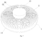
Fig. 7 is a schematic view of the fan lamp disclosed in an embodiment of the present disclosure from a slight downward angle. - 1-base, 10-fan groove, 100-fan sub-groove, 102-separation blade, 11-first light source setting area, 12-air outlet duct, 120-opening, 122-air deflector, 13-power supply cavity, 14-second light source setting area, 15-fairing ring, 2-fan, 3-first light-transmitting cover, 4-second light-transmitting cover, 5-back cover, 50-air inlet, 52-partition strip.
- In order to make the purpose, technical solution and advantages of the present application clearer, the technical solution of the present application will be described clearly and completely with reference to specific embodiments of the present application and corresponding drawings. Obviously, the described embodiments are only a part of the embodiments of the present application, but not all the embodiments. Based on the embodiments in the present application, all other embodiments obtained by ordinary technicians in the field without creative labor belong to the protection scope of the present application.
- The technical solutions provided by the embodiments of the present disclosure are described in detail below with reference to the accompanying drawings.
- An embodiment of the present disclosure discloses a fan lamp. As illustrated by
Figs. 1 to 6 , the fan lamp includes abase 1, a first light source module (not shown in the figure) and afan 2. Thebase 1 is a main body structure of the fan lamp and plays a role in fixing and protecting other components. - Specifically, the
base 1 includes a first side and a second side (not marked in the figure) which are away from each other, the first side includes afan groove 10, and a first light source setting area 11 (seeFig. 3 ) is arranged at the second side; and meanwhile, anair outlet duct 12 is further arranged on thebase 1 and communicated with thefan groove 10 and the second side, and anopening 120, at the second side, of theair outlet duct 12 surrounds the first lightsource setting area 11. - The light source module is arranged in the first light
source setting area 11, and thefan 2 is arranged in thefan groove 10. Because thefan 2 in the present embodiment is arranged in thefan groove 10, other directions, except the air inlet side, of thefan 2 are relatively closed, the fan can achieve the pressurization effect through such structure, the air inlet amount and the air outlet amount are increased, and therefore no too much distance needs to be reserved between thefan 2 and a ceiling in the embodiment, the overall floor height occupied by the fan lamp can be greatly reduced, the fan lamp is closer to the ceiling and is located at the position where people cannot touch the fan lamp easily, and the repression feeling brought by the lamp is effectively reduced. In addition, because the fan lamp is located at the position where people cannot touch the fan lamp easily, thefan 2 is arranged in thefan groove 10, no blade stretches out in the working state, so that the safety coefficient is higher. - The fan lamp generally includes a drive module (not shown in the figure), and in order to arrange the drive module, the
base 1 further includes apower supply cavity 13. Thepower supply cavity 13 is defined by a solid structure and protrudes out of the first side. In the embodiment, the opening of thepower supply cavity 13 is arranged at the second side, and a main body part extends and protrudes from the second side to the first side. Or, thepower supply cavity 13 is formed by adopting an outer cover to cover the first side, and the two structures can be selected according to needs. - As illustrated by
Fig. 4 , in the embodiment, thefan groove 10 can be arranged around thepower supply cavity 13 in order to ensure uniform air outlet. Because thefan 2 needs to be fed with air from the opening of thefan groove 10, a groove of thefan groove 10 cannot be clung to the ceiling upon the fan lamp being installed. In order to simplify the installation process, thepower supply cavity 13 in the embodiment can exceed the groove of thefan groove 10, so that enough gap for air feeding can be reserved between the groove of thefan groove 10 and the ceiling due to the obstruction of thepower supply cavity 13 upon the fan lamp being installed. - In the embodiment, one
fan 2 can be adopted, and a plurality offans 2 can also be adopted simultaneously. As illustrated byFig. 4 , in the case where only onefan 2 is adopted, thefan 2 is a turbofan, and the turbofan is sleeved around thepower supply cavity 13 during installing. - As illustrated by
Fig. 5 , in the case where the plurality offans 2 are adopted simultaneously in the embodiment, thefans 2 can be simultaneously arranged in thefan groove 10, but becausedifferent fans 2 can generate different air flows, in order to prevent the adjacent fans from interfering with each other, thefan groove 10 is divided into a plurality ofindependent fan sub-grooves 100, each of the plurality offan sub-grooves 100 is provided with one of the plurality offans 2, and theair outlet duct 12 extends to each of the plurality offan sub-grooves 100 simultaneously. Thefan sub-grooves 100 have a plurality of arrangement modes which are mainly designed according to the size of thefan 2 and the structure of theair outlet duct 12. In the embodiment, thefan sub-grooves 100 are preferably arranged along the circumferential direction, and thefan sub-grooves 100 can form a fan-shaped structure, a conch-shaped structure or other structures. Theair outlet duct 12 is positioned in the outer side area of the fan-shaped structure, thereby forming a larger air outlet ring. - Two
adjacent fan sub-grooves 100 can be separated by aseparation blade 102 or other parts, theseparation blade 102 can be integrally arranged with thefan groove 10, so that the separation blade is recommended to be adopted. - In the embodiment, in order to enable air blown by the plurality of
fans 2 to be blown as a whole, a plurality ofair deflectors 122 are uniformly distributed in theair outlet duct 12 along the circumferential direction, theair deflectors 122 can be integrally arranged with theair outlet duct 12 and can also be independently arranged in the form of air guide grooves, and all theair deflectors 122 are obliquely arranged relative to theopening 120 along the same clockwise direction (such as clockwise or anticlockwise). Therefore, the air blown by all thefans 2 can form vortex-shaped disturbance air, the flowing effect of the air can be improved, and the air volume can be increased. Moreover, eachfan 2 can be independently matched with different rotating speeds through a driving module, so that the air volume is locally adjusted, the superposition effect is changed, and more air outlet modes are realized. - In the embodiment, common lighting requirements can be met through the first light source module under normal conditions. Along with the improvement of the living standard, people have more requirements on the lighting effect of the lamp. In order to enable the fan lamp to have more diversified lighting effects, the fan lamp in the embodiment can further include a second light source module (not shown in the figure), a second light
source setting area 14 is further arranged at the second side, the second lightsource setting area 14 surrounds theopening 120, and the second light source module is arranged in the second lightsource setting area 14. - The second light source module can be a light-emitting device with different power or colors from the first light source module. For example, the second light source module can be a low-power light-emitting device, and upon a user only needing low-brightness illumination, the second light source module can be independently turned on. The first light source module can be independently turned on upon the middle brightness being needed. The first light source module and the second light source module can be turned on at the same time upon high brightness being needed, so that the fan lamp has various different brightness modes.
- Similarly, in the case the second light source module adopts light-emitting devices with different colors, the user can control the needed light source module to be turned on or off according to needs so as to present different color effects.
- As illustrated by the
Fig. 5 , in the embodiment, afairing ring 15 can be formed between the first lightsource setting area 11 and the second lightsource setting area 14 and is positioned in front of theopening 120. Airflow blown out of theopening 120 can be rectified in thefairing ring 15, the angle of the airflow can be adjusted, and the airflow divided into a plurality of parts by theair deflectors 122 can be integrated into a whole. The extending direction of thefairing ring 15 can face the lower portion and can also incline towards the inner side or the outer side. - In order to adjust the light emitting effect and improve the appearance of the fan lamp, the fan lamp in the embodiment can further include a first light-transmitting
cover 3 and a second light-transmittingcover 4, the first light-transmittingcover 3 is matched with the first lightsource setting area 11 in shape and covers the first lightsource setting area 11, and the second light-transmittingcover 4 is matched with the second lightsource setting area 14 in shape and covers the second lightsource setting area 14. Moreover, the first light-transmittingcover 3 and the second light-transmittingcover 4 in the embodiment can also play a role in prolonging the length of thefairing ring 15. - In the embodiment, a
back cover 5 matched with thefan groove 10 in shape can also cover thefan groove 10, as illustrated byFig. 6 , theback cover 5 is provided with anair inlet 50 at the position corresponding to eachfan 2, and the rest areas are all sealed, so that, on one hand, theback cover 5 can effectively protect thefans 2 and prevent the user from touching thefans 2. And, on the other hand, theback cover 5 can also improve the air inlet rate to a certain extent. - Furthermore, a plurality of partition strips 52 can also be arranged on aside, away from the
fan groove 10, of theback cover 5 at intervals, the arrangement mode of the partition strips 52 is not limited, and the partition strips can improve the structural strength of theback cover 5. When the partition strips extend to theair inlet 50, the partition strips are not segmented, but continue to extend across theair inlet 50, so that a layer of protection net can be formed at theair inlet 50, fingers or other objects of the user are prevented from extending into theair inlet 50, and the safety of the fan lamp is improved. - In conclusion, the fan lamp provided by the embodiment of the present disclosure greatly reduces the occupied space of the floor height and potential safety hazards.
- The abovementioned embodiments of the present disclosure focus on the differences between the various embodiments. As long as the different optimization features between the various embodiments are not contradictory, the embodiments can be combined to form a better embodiment. For the conciseness of the text, there is no more detailed description.
- The above are only embodiments of the present disclosure and are not intended to limit the present disclosure. For those skilled in the art, various modifications and changes on the present disclosure are available. Any modifications, equivalents, improvements, etc. made within the spirit and principle of the present disclosure should be included in the protection ranges of the claims of the present disclosure.
Claims (12)
- A fan lamp, comprising a base, a first light source module and a fan;wherein the base comprises a first side and a second side which are away from each other, a fan groove is formed at the first side, and a first light source setting area is arranged at the second side, an air outlet duct is further arranged on the base and communicated with the fan groove and the second side, and an opening, at the second side, of the air outlet duct surrounds the first light source setting area;and the light source module is arranged in the first light source setting area, and the fan is arranged in the fan groove.
- The fan lamp according to claim 1, wherein the base further includes a power supply cavity, the power supply cavity protrudes out of the first side, the fan groove is arranged around the power supply cavity, and the power supply cavity exceeds a groove of the fan groove.
- The fan lamp according to claim 2, wherein a plurality of fans are provided, and the fan groove is divided into a plurality of independent fan sub-grooves, each of the plurality of fan sub-grooves is provided with one of the plurality of fans, and the air outlet duct extends to each of the plurality of fan sub-grooves.
- The fan lamp according to claim 3, wherein the plurality of fan sub-grooves are arranged along a circumferential direction.
- The fan lamp according to claim 4, wherein a separation blade is arranged in the fan groove, and two adjacent ones of the plurality of fan sub-grooves are separated by the separation blade.
- The fan lamp according to claim 2, wherein the fan is a turbofan, and the turbofan is sleeved around the power supply cavity.
- The fan lamp according to any one of claims 1 to 6, wherein a plurality of air deflectors are uniformly distributed in the air outlet duct along a circumferential direction, and all of the plurality of air deflectors are obliquely arranged relative to the opening along a same clockwise direction.
- The fan lamp according to any one of claims 1 to 6, wherein the fan lamp further comprises a second light source module, a second light source setting area is further arranged at the second side, the second light source setting area surrounds the opening, and the second light source module is arranged in the second light source setting area.
- The fan lamp according to claim 8, wherein a fairing ring is formed between the first light source setting area and the second light source setting area and is positioned in front of the opening.
- The fan lamp according to claim 8, wherein the fan lamp further comprises a first light-transmitting cover and a second light-transmitting cover, the first light-transmitting cover is matched with the first light source setting area in shape and covers the first light source setting area, and the second light-transmitting cover is matched with the second light source setting area in shape and covers the second light source setting area.
- The fan lamp according to any one of claims 1 to 6, wherein the fan lamp further comprises a back cover, the back cover is matched with the fan groove in shape and covers the fan groove, and the back cover is provided with an air inlet at a position corresponding to the fan.
- The fan lamp according to claim 11, wherein a plurality of partition strips are arranged at a side, away from the fan groove, of the back cover at intervals, and a part of the plurality of partition strips extends across the air inlet.
Applications Claiming Priority (2)
| Application Number | Priority Date | Filing Date | Title |
|---|---|---|---|
| CN201822184347.2U CN209012971U (en) | 2018-12-25 | 2018-12-25 | Fan lamp |
| PCT/CN2019/128270 WO2020135496A1 (en) | 2018-12-25 | 2019-12-25 | Fan lamp |
Publications (3)
| Publication Number | Publication Date |
|---|---|
| EP3882512A1 true EP3882512A1 (en) | 2021-09-22 |
| EP3882512A4 EP3882512A4 (en) | 2022-01-19 |
| EP3882512B1 EP3882512B1 (en) | 2024-11-06 |
Family
ID=66844167
Family Applications (1)
| Application Number | Title | Priority Date | Filing Date |
|---|---|---|---|
| EP19905171.5A Active EP3882512B1 (en) | 2018-12-25 | 2019-12-25 | Fan lamp |
Country Status (4)
| Country | Link |
|---|---|
| US (1) | US20210317982A1 (en) |
| EP (1) | EP3882512B1 (en) |
| CN (1) | CN209012971U (en) |
| WO (1) | WO2020135496A1 (en) |
Families Citing this family (7)
| Publication number | Priority date | Publication date | Assignee | Title |
|---|---|---|---|---|
| CN209012971U (en) * | 2018-12-25 | 2019-06-21 | 欧普照明股份有限公司 | Fan lamp |
| CN111140545B (en) * | 2020-01-19 | 2025-03-28 | 漳州立达信光电子科技有限公司 | Ceiling fan light with air duct |
| CN111878436A (en) * | 2020-08-26 | 2020-11-03 | 深圳市华丫科技有限公司 | Hanging fan |
| CN112228850A (en) * | 2020-11-09 | 2021-01-15 | 段盛飞 | A new type of eddy current fan lamp |
| US11686321B2 (en) * | 2021-11-10 | 2023-06-27 | Air Cool Industrial Co., Ltd. | Ceiling fan having double-layer blades |
| CN114992147A (en) * | 2022-07-22 | 2022-09-02 | 东莞市嘉恩塑胶机电科技有限公司 | Energy-conserving planet wheel fan of frequency conversion with function can give out light |
| US12359802B1 (en) | 2024-12-31 | 2025-07-15 | Huankun Xue | Fan ceiling lamp |
Family Cites Families (27)
| Publication number | Priority date | Publication date | Assignee | Title |
|---|---|---|---|---|
| US6752587B2 (en) * | 2002-08-07 | 2004-06-22 | Inventec Corporation | Modular fan assembly |
| UA107094C2 (en) * | 2009-11-03 | 2014-11-25 | CENTRAL CEILING FAN | |
| WO2012174155A1 (en) * | 2011-06-15 | 2012-12-20 | Airius Ip Holdings, Llc | Columnar air moving devices, systems and methods |
| CN103827581A (en) * | 2011-09-26 | 2014-05-28 | 普司科Led股份有限公司 | Optical semiconductor-based lighting apparatus |
| CN203068344U (en) * | 2012-09-29 | 2013-07-17 | 东莞巨扬电器有限公司 | Ceiling lights that generate airflow |
| TW201425811A (en) * | 2012-12-20 | 2014-07-01 | Chang Wah Electromaterials Inc | Solid-state illuminator with air passage |
| NL1040116B3 (en) * | 2013-03-22 | 2026-04-23 | Nges Holding B V | Illumination device for stimulating plant growth. |
| CN203258626U (en) * | 2013-04-08 | 2013-10-30 | 宝弘实业股份有限公司 | Lamp base structure with hidden fan |
| US10677250B2 (en) * | 2014-08-13 | 2020-06-09 | Sectar Solutions Inc. | Centrifugal ceiling fan |
| US20160169503A1 (en) * | 2014-12-14 | 2016-06-16 | Shih-Yun Chen | Led lamp for ceiling fan and ceiling fan having the same |
| US20160341400A1 (en) * | 2015-05-22 | 2016-11-24 | Posco Led Company Ltd. | Optical semiconductor lighting apparatus |
| CN106287457A (en) * | 2015-06-11 | 2017-01-04 | 陈镒明 | Multifunctional lamp fan device |
| US9541278B2 (en) * | 2015-06-11 | 2017-01-10 | Youngo Limited | Ceiling fan structure with led lamp |
| US9429286B2 (en) * | 2015-06-23 | 2016-08-30 | Ching-Wen Liu | Combination ceiling fan and lamp |
| US9895202B2 (en) * | 2015-07-01 | 2018-02-20 | Sld Technology, Inc. | Airflow-channeling surgical light system and method |
| US10247191B2 (en) * | 2016-12-28 | 2019-04-02 | WLC Enterprises, Inc. | Combined LED light and fan apparatus |
| CN206875269U (en) * | 2017-04-28 | 2018-01-12 | 深圳市金盈家电器有限公司 | Fan lighting device |
| CN209638120U (en) * | 2017-10-20 | 2019-11-15 | 创科(澳门离岸商业服务)有限公司 | fan |
| CN207471227U (en) * | 2017-10-25 | 2018-06-08 | 江西美的贵雅照明有限公司 | Lamps and lanterns |
| CN107957029A (en) * | 2017-12-08 | 2018-04-24 | 广东旺来新材料科技股份有限公司 | A kind of lighting device with anion ventilation function |
| US20190234423A1 (en) * | 2018-02-01 | 2019-08-01 | Tti (Macao Commercial Offshore) Limited | Fan |
| US20190242391A1 (en) * | 2018-02-07 | 2019-08-08 | Tti (Macao Commercial Offshore) Limited | Ceiling fan |
| CN209012971U (en) * | 2018-12-25 | 2019-06-21 | 欧普照明股份有限公司 | Fan lamp |
| US20220235782A1 (en) * | 2019-06-07 | 2022-07-28 | Beacon Lighting International Limited | Airflow device |
| CN110360475B (en) * | 2019-08-09 | 2024-11-05 | 佛山市清源科技有限公司 | Lighting device with silent and high air volume air duct structure |
| WO2022001875A1 (en) * | 2020-06-30 | 2022-01-06 | 苏州欧普照明有限公司 | Fan lamp |
| CN216111386U (en) * | 2021-10-18 | 2022-03-22 | 佛山市启正电气有限公司 | Hanging head connecting mechanism and ceiling fan thereof |
-
2018
- 2018-12-25 CN CN201822184347.2U patent/CN209012971U/en not_active Expired - Fee Related
-
2019
- 2019-12-25 EP EP19905171.5A patent/EP3882512B1/en active Active
- 2019-12-25 WO PCT/CN2019/128270 patent/WO2020135496A1/en not_active Ceased
-
2021
- 2021-06-24 US US17/357,911 patent/US20210317982A1/en not_active Abandoned
Also Published As
| Publication number | Publication date |
|---|---|
| EP3882512A4 (en) | 2022-01-19 |
| EP3882512B1 (en) | 2024-11-06 |
| US20210317982A1 (en) | 2021-10-14 |
| CN209012971U (en) | 2019-06-21 |
| WO2020135496A1 (en) | 2020-07-02 |
Similar Documents
| Publication | Publication Date | Title |
|---|---|---|
| EP3882512B1 (en) | Fan lamp | |
| CN102797990A (en) | Led lamp | |
| EP2813768B1 (en) | Air conditioner with illumination | |
| CN105222259A (en) | A kind of Integral ceiling ventilation wind warms up lighting all-in-one machine | |
| CN210123118U (en) | Bladeless fan lamp | |
| JP3173183U (en) | Lighting around | |
| CN110159566A (en) | A kind of no leaf Ceiling fan lamp | |
| CN103994087A (en) | Fan with light emission function | |
| CN205174650U (en) | Integrated furred ceiling warm illumination all -in -one of wind of taking a breath | |
| CN210128289U (en) | Lamp with heating or refrigerating function | |
| CN204678181U (en) | An automatic cooling LED panel light | |
| CN215062327U (en) | Heating air-out structure and room heater | |
| CN204553282U (en) | The circle that a kind of suspended ceiling with illumination function is installed is without blade fan | |
| CN205225781U (en) | Ceiling fan with illumination function | |
| CN108868037A (en) | The decorative board for packet wall with light-emitting function | |
| CN213300045U (en) | Novel vortex fan lamp | |
| CN112228850A (en) | A new type of eddy current fan lamp | |
| CN223036493U (en) | Bathroom heater and panel unit thereof | |
| JP3231115U (en) | Ceiling fan light | |
| CN224064542U (en) | Bladeless fan lamp | |
| CN212106335U (en) | Assembly structure of linear fan | |
| CN206890641U (en) | The isolated integration ceiling warmer of circuit illuminator | |
| CN211314644U (en) | Double-air-duct air outlet structure | |
| CN106642375A (en) | Air mist sprayer | |
| CN110952738A (en) | Television background wallboard with temperature and humidity adjusting function |
Legal Events
| Date | Code | Title | Description |
|---|---|---|---|
| STAA | Information on the status of an ep patent application or granted ep patent |
Free format text: STATUS: THE INTERNATIONAL PUBLICATION HAS BEEN MADE |
|
| PUAI | Public reference made under article 153(3) epc to a published international application that has entered the european phase |
Free format text: ORIGINAL CODE: 0009012 |
|
| STAA | Information on the status of an ep patent application or granted ep patent |
Free format text: STATUS: REQUEST FOR EXAMINATION WAS MADE |
|
| 17P | Request for examination filed |
Effective date: 20210616 |
|
| AK | Designated contracting states |
Kind code of ref document: A1 Designated state(s): AL AT BE BG CH CY CZ DE DK EE ES FI FR GB GR HR HU IE IS IT LI LT LU LV MC MK MT NL NO PL PT RO RS SE SI SK SM TR |
|
| A4 | Supplementary search report drawn up and despatched |
Effective date: 20211216 |
|
| RIC1 | Information provided on ipc code assigned before grant |
Ipc: F04D 25/16 20060101ALN20211210BHEP Ipc: F21Y 105/18 20160101ALN20211210BHEP Ipc: F21V 29/83 20150101ALN20211210BHEP Ipc: F21V 29/67 20150101ALN20211210BHEP Ipc: F21V 3/02 20060101ALN20211210BHEP Ipc: F04D 29/00 20060101ALI20211210BHEP Ipc: F04D 25/08 20060101ALI20211210BHEP Ipc: F21V 33/00 20060101ALI20211210BHEP Ipc: F21S 8/04 20060101AFI20211210BHEP |
|
| DAV | Request for validation of the european patent (deleted) | ||
| DAX | Request for extension of the european patent (deleted) | ||
| RIC1 | Information provided on ipc code assigned before grant |
Ipc: F04D 25/16 20060101ALN20240515BHEP Ipc: F21Y 105/18 20160101ALN20240515BHEP Ipc: F21V 29/83 20150101ALN20240515BHEP Ipc: F21V 29/67 20150101ALN20240515BHEP Ipc: F21V 3/02 20060101ALN20240515BHEP Ipc: F04D 29/00 20060101ALI20240515BHEP Ipc: F04D 25/08 20060101ALI20240515BHEP Ipc: F21V 33/00 20060101ALI20240515BHEP Ipc: F21S 8/04 20060101AFI20240515BHEP |
|
| GRAP | Despatch of communication of intention to grant a patent |
Free format text: ORIGINAL CODE: EPIDOSNIGR1 |
|
| STAA | Information on the status of an ep patent application or granted ep patent |
Free format text: STATUS: GRANT OF PATENT IS INTENDED |
|
| INTG | Intention to grant announced |
Effective date: 20240628 |
|
| GRAS | Grant fee paid |
Free format text: ORIGINAL CODE: EPIDOSNIGR3 |
|
| GRAA | (expected) grant |
Free format text: ORIGINAL CODE: 0009210 |
|
| STAA | Information on the status of an ep patent application or granted ep patent |
Free format text: STATUS: THE PATENT HAS BEEN GRANTED |
|
| AK | Designated contracting states |
Kind code of ref document: B1 Designated state(s): AL AT BE BG CH CY CZ DE DK EE ES FI FR GB GR HR HU IE IS IT LI LT LU LV MC MK MT NL NO PL PT RO RS SE SI SK SM TR |
|
| REG | Reference to a national code |
Ref country code: GB Ref legal event code: FG4D |
|
| REG | Reference to a national code |
Ref country code: CH Ref legal event code: EP |
|
| REG | Reference to a national code |
Ref country code: DE Ref legal event code: R096 Ref document number: 602019061736 Country of ref document: DE |
|
| REG | Reference to a national code |
Ref country code: IE Ref legal event code: FG4D |
|
| REG | Reference to a national code |
Ref country code: NL Ref legal event code: FP |
|
| REG | Reference to a national code |
Ref country code: LT Ref legal event code: MG9D |
|
| PG25 | Lapsed in a contracting state [announced via postgrant information from national office to epo] |
Ref country code: HR Free format text: LAPSE BECAUSE OF FAILURE TO SUBMIT A TRANSLATION OF THE DESCRIPTION OR TO PAY THE FEE WITHIN THE PRESCRIBED TIME-LIMIT Effective date: 20241106 Ref country code: PT Free format text: LAPSE BECAUSE OF FAILURE TO SUBMIT A TRANSLATION OF THE DESCRIPTION OR TO PAY THE FEE WITHIN THE PRESCRIBED TIME-LIMIT Effective date: 20250306 Ref country code: IS Free format text: LAPSE BECAUSE OF FAILURE TO SUBMIT A TRANSLATION OF THE DESCRIPTION OR TO PAY THE FEE WITHIN THE PRESCRIBED TIME-LIMIT Effective date: 20250306 |
|
| PG25 | Lapsed in a contracting state [announced via postgrant information from national office to epo] |
Ref country code: FI Free format text: LAPSE BECAUSE OF FAILURE TO SUBMIT A TRANSLATION OF THE DESCRIPTION OR TO PAY THE FEE WITHIN THE PRESCRIBED TIME-LIMIT Effective date: 20241106 |
|
| REG | Reference to a national code |
Ref country code: AT Ref legal event code: MK05 Ref document number: 1739688 Country of ref document: AT Kind code of ref document: T Effective date: 20241106 |
|
| PG25 | Lapsed in a contracting state [announced via postgrant information from national office to epo] |
Ref country code: BG Free format text: LAPSE BECAUSE OF FAILURE TO SUBMIT A TRANSLATION OF THE DESCRIPTION OR TO PAY THE FEE WITHIN THE PRESCRIBED TIME-LIMIT Effective date: 20241106 |
|
| PG25 | Lapsed in a contracting state [announced via postgrant information from national office to epo] |
Ref country code: ES Free format text: LAPSE BECAUSE OF FAILURE TO SUBMIT A TRANSLATION OF THE DESCRIPTION OR TO PAY THE FEE WITHIN THE PRESCRIBED TIME-LIMIT Effective date: 20241106 |
|
| PG25 | Lapsed in a contracting state [announced via postgrant information from national office to epo] |
Ref country code: NO Free format text: LAPSE BECAUSE OF FAILURE TO SUBMIT A TRANSLATION OF THE DESCRIPTION OR TO PAY THE FEE WITHIN THE PRESCRIBED TIME-LIMIT Effective date: 20250206 |
|
| PG25 | Lapsed in a contracting state [announced via postgrant information from national office to epo] |
Ref country code: GR Free format text: LAPSE BECAUSE OF FAILURE TO SUBMIT A TRANSLATION OF THE DESCRIPTION OR TO PAY THE FEE WITHIN THE PRESCRIBED TIME-LIMIT Effective date: 20250207 Ref country code: LV Free format text: LAPSE BECAUSE OF FAILURE TO SUBMIT A TRANSLATION OF THE DESCRIPTION OR TO PAY THE FEE WITHIN THE PRESCRIBED TIME-LIMIT Effective date: 20241106 Ref country code: AT Free format text: LAPSE BECAUSE OF FAILURE TO SUBMIT A TRANSLATION OF THE DESCRIPTION OR TO PAY THE FEE WITHIN THE PRESCRIBED TIME-LIMIT Effective date: 20241106 |
|
| PG25 | Lapsed in a contracting state [announced via postgrant information from national office to epo] |
Ref country code: PL Free format text: LAPSE BECAUSE OF FAILURE TO SUBMIT A TRANSLATION OF THE DESCRIPTION OR TO PAY THE FEE WITHIN THE PRESCRIBED TIME-LIMIT Effective date: 20241106 |
|
| PG25 | Lapsed in a contracting state [announced via postgrant information from national office to epo] |
Ref country code: RS Free format text: LAPSE BECAUSE OF FAILURE TO SUBMIT A TRANSLATION OF THE DESCRIPTION OR TO PAY THE FEE WITHIN THE PRESCRIBED TIME-LIMIT Effective date: 20250206 |
|
| PG25 | Lapsed in a contracting state [announced via postgrant information from national office to epo] |
Ref country code: SM Free format text: LAPSE BECAUSE OF FAILURE TO SUBMIT A TRANSLATION OF THE DESCRIPTION OR TO PAY THE FEE WITHIN THE PRESCRIBED TIME-LIMIT Effective date: 20241106 |
|
| PG25 | Lapsed in a contracting state [announced via postgrant information from national office to epo] |
Ref country code: DK Free format text: LAPSE BECAUSE OF FAILURE TO SUBMIT A TRANSLATION OF THE DESCRIPTION OR TO PAY THE FEE WITHIN THE PRESCRIBED TIME-LIMIT Effective date: 20241106 |
|
| PG25 | Lapsed in a contracting state [announced via postgrant information from national office to epo] |
Ref country code: EE Free format text: LAPSE BECAUSE OF FAILURE TO SUBMIT A TRANSLATION OF THE DESCRIPTION OR TO PAY THE FEE WITHIN THE PRESCRIBED TIME-LIMIT Effective date: 20241106 |
|
| PG25 | Lapsed in a contracting state [announced via postgrant information from national office to epo] |
Ref country code: RO Free format text: LAPSE BECAUSE OF FAILURE TO SUBMIT A TRANSLATION OF THE DESCRIPTION OR TO PAY THE FEE WITHIN THE PRESCRIBED TIME-LIMIT Effective date: 20241106 |
|
| PG25 | Lapsed in a contracting state [announced via postgrant information from national office to epo] |
Ref country code: SK Free format text: LAPSE BECAUSE OF FAILURE TO SUBMIT A TRANSLATION OF THE DESCRIPTION OR TO PAY THE FEE WITHIN THE PRESCRIBED TIME-LIMIT Effective date: 20241106 |
|
| PG25 | Lapsed in a contracting state [announced via postgrant information from national office to epo] |
Ref country code: CZ Free format text: LAPSE BECAUSE OF FAILURE TO SUBMIT A TRANSLATION OF THE DESCRIPTION OR TO PAY THE FEE WITHIN THE PRESCRIBED TIME-LIMIT Effective date: 20241106 |
|
| PG25 | Lapsed in a contracting state [announced via postgrant information from national office to epo] |
Ref country code: IT Free format text: LAPSE BECAUSE OF FAILURE TO SUBMIT A TRANSLATION OF THE DESCRIPTION OR TO PAY THE FEE WITHIN THE PRESCRIBED TIME-LIMIT Effective date: 20241106 |
|
| REG | Reference to a national code |
Ref country code: CH Ref legal event code: PL |
|
| REG | Reference to a national code |
Ref country code: DE Ref legal event code: R097 Ref document number: 602019061736 Country of ref document: DE |
|
| PG25 | Lapsed in a contracting state [announced via postgrant information from national office to epo] |
Ref country code: LU Free format text: LAPSE BECAUSE OF NON-PAYMENT OF DUE FEES Effective date: 20241225 |
|
| PG25 | Lapsed in a contracting state [announced via postgrant information from national office to epo] |
Ref country code: SE Free format text: LAPSE BECAUSE OF FAILURE TO SUBMIT A TRANSLATION OF THE DESCRIPTION OR TO PAY THE FEE WITHIN THE PRESCRIBED TIME-LIMIT Effective date: 20241106 |
|
| PLBE | No opposition filed within time limit |
Free format text: ORIGINAL CODE: 0009261 |
|
| STAA | Information on the status of an ep patent application or granted ep patent |
Free format text: STATUS: NO OPPOSITION FILED WITHIN TIME LIMIT |
|
| PG25 | Lapsed in a contracting state [announced via postgrant information from national office to epo] |
Ref country code: MC Free format text: LAPSE BECAUSE OF FAILURE TO SUBMIT A TRANSLATION OF THE DESCRIPTION OR TO PAY THE FEE WITHIN THE PRESCRIBED TIME-LIMIT Effective date: 20241106 |
|
| 26N | No opposition filed |
Effective date: 20250807 |
|
| PG25 | Lapsed in a contracting state [announced via postgrant information from national office to epo] |
Ref country code: CH Free format text: LAPSE BECAUSE OF NON-PAYMENT OF DUE FEES Effective date: 20241231 |
|
| PG25 | Lapsed in a contracting state [announced via postgrant information from national office to epo] |
Ref country code: IE Free format text: LAPSE BECAUSE OF NON-PAYMENT OF DUE FEES Effective date: 20241225 |
|
| PGFP | Annual fee paid to national office [announced via postgrant information from national office to epo] |
Ref country code: NL Payment date: 20251127 Year of fee payment: 7 |
|
| PGFP | Annual fee paid to national office [announced via postgrant information from national office to epo] |
Ref country code: GB Payment date: 20251229 Year of fee payment: 7 |
|
| PGFP | Annual fee paid to national office [announced via postgrant information from national office to epo] |
Ref country code: FR Payment date: 20251230 Year of fee payment: 7 |
|
| PGFP | Annual fee paid to national office [announced via postgrant information from national office to epo] |
Ref country code: BE Payment date: 20251226 Year of fee payment: 7 |
|
| PGFP | Annual fee paid to national office [announced via postgrant information from national office to epo] |
Ref country code: DE Payment date: 20251231 Year of fee payment: 7 |
|
| PG25 | Lapsed in a contracting state [announced via postgrant information from national office to epo] |
Ref country code: CY Free format text: LAPSE BECAUSE OF FAILURE TO SUBMIT A TRANSLATION OF THE DESCRIPTION OR TO PAY THE FEE WITHIN THE PRESCRIBED TIME-LIMIT Effective date: 20241106 |