EP3882486A1 - Double nut stroke adjustment travel stop - Google Patents
Double nut stroke adjustment travel stop Download PDFInfo
- Publication number
- EP3882486A1 EP3882486A1 EP20275060.0A EP20275060A EP3882486A1 EP 3882486 A1 EP3882486 A1 EP 3882486A1 EP 20275060 A EP20275060 A EP 20275060A EP 3882486 A1 EP3882486 A1 EP 3882486A1
- Authority
- EP
- European Patent Office
- Prior art keywords
- nut
- rod
- shaft
- hook
- stop
- Prior art date
- Legal status (The legal status is an assumption and is not a legal conclusion. Google has not performed a legal analysis and makes no representation as to the accuracy of the status listed.)
- Pending
Links
Images
Classifications
-
- F—MECHANICAL ENGINEERING; LIGHTING; HEATING; WEAPONS; BLASTING
- F16—ENGINEERING ELEMENTS AND UNITS; GENERAL MEASURES FOR PRODUCING AND MAINTAINING EFFECTIVE FUNCTIONING OF MACHINES OR INSTALLATIONS; THERMAL INSULATION IN GENERAL
- F16H—GEARING
- F16H25/00—Gearings comprising primarily only cams, cam-followers and screw-and-nut mechanisms
- F16H25/18—Gearings comprising primarily only cams, cam-followers and screw-and-nut mechanisms for conveying or interconverting oscillating or reciprocating motions
- F16H25/20—Screw mechanisms
- F16H25/2015—Means specially adapted for stopping actuators in the end position; Position sensing means
-
- F—MECHANICAL ENGINEERING; LIGHTING; HEATING; WEAPONS; BLASTING
- F16—ENGINEERING ELEMENTS AND UNITS; GENERAL MEASURES FOR PRODUCING AND MAINTAINING EFFECTIVE FUNCTIONING OF MACHINES OR INSTALLATIONS; THERMAL INSULATION IN GENERAL
- F16H—GEARING
- F16H25/00—Gearings comprising primarily only cams, cam-followers and screw-and-nut mechanisms
- F16H25/18—Gearings comprising primarily only cams, cam-followers and screw-and-nut mechanisms for conveying or interconverting oscillating or reciprocating motions
- F16H25/20—Screw mechanisms
- F16H25/24—Elements essential to such mechanisms, e.g. screws, nuts
-
- F—MECHANICAL ENGINEERING; LIGHTING; HEATING; WEAPONS; BLASTING
- F16—ENGINEERING ELEMENTS AND UNITS; GENERAL MEASURES FOR PRODUCING AND MAINTAINING EFFECTIVE FUNCTIONING OF MACHINES OR INSTALLATIONS; THERMAL INSULATION IN GENERAL
- F16H—GEARING
- F16H25/00—Gearings comprising primarily only cams, cam-followers and screw-and-nut mechanisms
- F16H25/18—Gearings comprising primarily only cams, cam-followers and screw-and-nut mechanisms for conveying or interconverting oscillating or reciprocating motions
- F16H25/20—Screw mechanisms
- F16H2025/204—Axial sliding means, i.e. for rotary support and axial guiding of nut or screw shaft
Definitions
- the present disclosure relates to an over travel stop unit for actuator valves.
- the present disclosure relates to an assembly and a method of adjustment for an over travel stop unit.
- Actuators require accurate travel stop adjustments at ends of the stroke to obtain optimal performance and valve seat life.
- an actuator system includes travel stops and components specific to that particular actuator system.
- the length of the screw will be specific to the stroke requirement of that particular actuator system.
- a travel stop assembly for an actuator.
- the travel stop assembly includes a housing, a shaft provided along a longitudinal axis.
- the shaft has a first end and a second end.
- the travel stop assembly also includes a first nut and a second nut provided on the shaft, wherein there is provided a first gap between the first nut and the second nut.
- the travel stop assembly also includes a second gap provided between the second nut and the first end of the shaft, and means for adjusting the position of the first nut and the second nut such that the second gap is maintained.
- the means for adjusting the position of the first nut and the second nut may further include a first rod and a second rod provided at an inner wall of the housing.
- the first nut may include a first hook and a second hook that are configured to engage the first rod and the second rod.
- the second nut may include a first hook and a second hook that are configured to engage the first rod and the second rod.
- the first rod and second rod may be parallel to the shaft, and the first rod may be opposite the second rod.
- the travel stop assembly may further include a first end stop provided at the second end of the shaft, a second end stop provided on one side of the first nut, a third end stop provided at the first end of the shaft, and a fourth end stop provided on one side of the second nut.
- the second gap may be provided between the third end stop and the fourth end stop.
- the second end stop may include at least one protrusion that extends radially away from the surface of the first nut along the longitudinal axis.
- the fourth end stop may also include at least one protrusion that extends radially away from the surface of the second nut along the longitudinal axis.
- the shaft is a threaded screw.
- actuator assembly including the travel stop assembly as described above.
- a method of adjusting a resultant stroke gap of a travel stop unit which includes providing a shaft along a longitudinal axis, the shaft having a first end and a second end, providing a first nut and a second nut on the shaft, providing a first gap between the first nut and the second nut, providing a second gap between the second nut and the first end of the shaft, and adjusting the position of the first nut and the second nut such that the second gap is maintained in a housing.
- adjusting the position of the first nut and the second nut may further include providing a first rod and a second rod at an inner wall of the housing, and engaging a first hook and a second hook of the first nut to the first rod and the second rod, and engaging a first hook and a second hook of the second nut to the first rod and the second rod.
- the first rod and second rod may be parallel to the shaft, and the first rod may be opposite the second rod.
- the method may further include providing a first end stop at the second end of the shaft, providing a second end stop on one side of the first nut, providing a third end stop at the first end of the shaft, and providing a fourth end stop on one side of the second nut.
- the second gap may be provided between the third end stop and the fourth end stop.
- the second end stop may further comprise at least one protrusion that extends radially away from the surface of the first nut along the longitudinal axis
- the fourth end stop may further comprise at least one protrusion that extends radially away from the surface of the second nut along the longitudinal axis.
- the assembly 10 may also be known as an over travel stop unit.
- the assembly 10 may include a housing 100 to house various components that allow for adjustment of the travel stop.
- the assembly 10 may have a longitudinal axis A running through the centre of the assembly 10 and the housing 100 may be provided about this longitudinal axis A.
- a shaft for example, a threaded screw 200 along the longitudinal axis A of the assembly 10.
- a first nut 201 and a second nut 202 can be received on the threaded screw 200.
- An adjustment gap A g may be formed between the first nut 201 and the second nut 202. This may be done manually by an engineer before incorporating the components for the assembly 10 in the housing 100.
- a first rod 101 may be provided at an inner wall 100' of the housing 100.
- the first rod 101 runs parallel to the threaded screw 200.
- a second rod 102 may be provided at the inner wall 100' of the housing 100, opposite the first rod 101.
- the first rod 101 and the second rod 102 are cylindrical.
- other geometries could be used as well to allow the first nut 201 and second nut 202 to engage with the first rod 101 and second rod 102, as described in more detail below.
- the threaded screw 200 has a first end 203 and a second end 204.
- a first end stop 214 Provided at the second end 204 of the threaded screw 200 is a first end stop 214.
- a second end stop 211 Provided on one side of the first nut 201 is a second end stop 211 that faces the first end stop 214 (i.e., the second end stop 211 is to the right hand side of the first nut 201).
- Provided on one side of the second nut 202 is a fourth end stop 212 that faces the third end stop 213 (i.e., the fourth end stop 212 is provided on the left hand side of the second nut 202).
- the gap between the third end stop 213 and the fourth end stop 212 is designated by the reference S g and refers to the resultant stroke gap.
- a user can adjust the resultant stroke gap S g by placing the first nut 201 and second nut 202 at the desired positions on the threaded screw 200. The user can then engage the threaded screw 200 in the housing 100.
- An axial screw 301 is applied to the threaded screw 200 to maintain the position of the threaded screw 200 in the housing 100.
- an adjustment means 300 which may be in the form of an exposed outer spline of the threaded screw 200. This is described in more detail below.
- the first nut 201 and the second nut 202 are shown.
- the first nut 201 may include a first hook 221 that extends radially from the overall surface of the first nut 201.
- the first nut 201 may also include a second hook 222 that also extends radially from the overall surface of the first nut 201.
- the first hook 221 of the first nut 201 therefore, provides a first hook surface 221' that can interact with one of the first rod 101 or the second rod 102 (as shown in Figure 1 ), in use.
- the first hook surface 221' is perpendicular to the overall surface of the first nut 201 and is configured to receive one of the first rod 101 or the second rod 102 (e.g. it includes a recess (not shown) that is sized and shaped to receive either the first rod 101 or the second rod 102).
- the second hook 222 also may provide a second hook surface 222' that can interact with one of the first rod 101 or the second rod 102, in use.
- the second hook surface 222' is perpendicular to the overall surface of the first nut 201 and is configured to receive one of the first rod 101 or the second rod 102 (e.g. it includes a recess (not shown) that is sized and shaped to receive either the first rod 101 or the second rod 102).
- the first nut 201 may have a first protrusion 223 and a second protrusion 224 that extend radially from the surface of the first nut 201 along the longitudinal axis.
- the first protrusion 223 and second protrusion 224 may therefore act as the second end stop 211 shown in Figure 1 .
- the second nut 202 may include a first hook 231 that extends radially from the surface of the second nut 202.
- the second nut 202 may also include a second hook 232 that also extends radially from the surface of the second nut 202.
- the first hook 231 of the second nut 202 therefore, provides a first hook surface 231' that can interact with one of the first rod 101 or the second rod 102 (as shown in Figure 1 ), in use.
- the first hook surface 231' is perpendicular to the overall surface of the second nut 202 and is configured to receive one of the first rod 101 or the second rod 102 (e.g.
- the second hook 232 also may provide a second hook surface 232' that can interact with one of the first rod 101 or the second rod 102, in use.
- the second hook surface 232' is perpendicular to the overall surface of the second nut 202 and is configured to receive one of the first rod 101 or the second rod 102 (e.g. it includes a recess (not shown) that is sized and shaped to receive either the first rod 101 or the second rod 102).
- the second nut 202 may have a first protrusion 233 and a second protrusion (not shown) that extend radially from the surface of the first nut 201 along the longitudinal axis.
- the first protrusion 233 and second protrusion (not shown) may therefore act as the fourth end stop 212 shown in Figure 1 .
- the first nut 201 and the second nut 202 are arranged such that protrusions 223, 224 and 233 are facing away from each other.
- the first nut 201 and the second nut 202 are arranged on the threaded screw 200, they are equal parts inversed along the longitudinal axis.
- the first nut 201 and second nut 202 may be introduced on to the threaded screw 200 by the user.
- the user may first determine and set the position of the first nut 201 and the second nut 202 to result in the adjustment gap A g (i.e., the space between the first nut 201 and the second nut 202).
- the user may then set the resultant stroke gap, S g , by turning the threaded screw 200 with the adjustment means 300.
- the first hook surface 221' of the first nut 201 may contact one of either the first rod 101 or the second rod 102.
- the second hook surface 222' of the first nut 201 may then contact the other of either the first rod 101 or the second rod 102 (i.e., the rod that is not being contacted by the first hook surface 221' of the first nut 201).
- the first hook surface 231' of the second nut 202 may also contact either one of the first rod 101 or the second rod 102.
- the second hook surface 232' of the second nut 202 may then contact the other of either the first rod 101 or the second rod 102 (i.e., the rod that is not being contacted by the first hook surface 231' of the second nut 202).
- first hook surfaces 221' and 231', and the second hook surfaces 222' and 232', of the first and second nut 201 and 202 are engaged with the first rod 101 and the second rod 102, the first nut 201 and the second nut 202 are then set in position, which results in the resultant stroke gap S g .
- Figure 3 shows an alternative nut 400 that could replace the first nut 201 and second nut 202 described above.
- a nut 400 (which could form the first nut 201 and the second nut 202 described above) that may include a first hook 401, a second hook 402, a third hook 403, a fourth hook 404, a fifth hook 405 and a sixth hook 406.
- the user may have smaller turns to engage the first rod 101 and the second rod 102, which allows for a more accurate adjustment of the resultant stroke gap S g .
- the nut 400 in this example, includes six hooks, but that any number of hooks of more than two could replace the hooks described in relation to the first nut 201 and second nut 202 in Figure 2 .
Landscapes
- Engineering & Computer Science (AREA)
- General Engineering & Computer Science (AREA)
- Mechanical Engineering (AREA)
- Transmission Devices (AREA)
Abstract
Description
- The present disclosure relates to an over travel stop unit for actuator valves. In particular, the present disclosure relates to an assembly and a method of adjustment for an over travel stop unit.
- Actuators require accurate travel stop adjustments at ends of the stroke to obtain optimal performance and valve seat life. In normal conditions, an actuator system includes travel stops and components specific to that particular actuator system. For example, the length of the screw will be specific to the stroke requirement of that particular actuator system. There is, therefore, a need for providing an adjustable travel stop unit that can be retrofitted to a range of actuator systems.
- In one example, there is provided a travel stop assembly for an actuator. The travel stop assembly includes a housing, a shaft provided along a longitudinal axis. The shaft has a first end and a second end. The travel stop assembly also includes a first nut and a second nut provided on the shaft, wherein there is provided a first gap between the first nut and the second nut. The travel stop assembly also includes a second gap provided between the second nut and the first end of the shaft, and means for adjusting the position of the first nut and the second nut such that the second gap is maintained.
- Preferably, the means for adjusting the position of the first nut and the second nut may further include a first rod and a second rod provided at an inner wall of the housing. The first nut may include a first hook and a second hook that are configured to engage the first rod and the second rod. Further, the second nut may include a first hook and a second hook that are configured to engage the first rod and the second rod.
- The first rod and second rod may be parallel to the shaft, and the first rod may be opposite the second rod.
- The travel stop assembly may further include a first end stop provided at the second end of the shaft, a second end stop provided on one side of the first nut, a third end stop provided at the first end of the shaft, and a fourth end stop provided on one side of the second nut. The second gap may be provided between the third end stop and the fourth end stop.
- The second end stop may include at least one protrusion that extends radially away from the surface of the first nut along the longitudinal axis. The fourth end stop may also include at least one protrusion that extends radially away from the surface of the second nut along the longitudinal axis.
- Preferably, the shaft is a threaded screw.
- There is also provided an actuator assembly including the travel stop assembly as described above.
- There is also provided a method of adjusting a resultant stroke gap of a travel stop unit, which includes providing a shaft along a longitudinal axis, the shaft having a first end and a second end, providing a first nut and a second nut on the shaft, providing a first gap between the first nut and the second nut, providing a second gap between the second nut and the first end of the shaft, and adjusting the position of the first nut and the second nut such that the second gap is maintained in a housing.
- Preferably, adjusting the position of the first nut and the second nut may further include providing a first rod and a second rod at an inner wall of the housing, and engaging a first hook and a second hook of the first nut to the first rod and the second rod, and engaging a first hook and a second hook of the second nut to the first rod and the second rod. The first rod and second rod may be parallel to the shaft, and the first rod may be opposite the second rod.
- The method may further include providing a first end stop at the second end of the shaft, providing a second end stop on one side of the first nut, providing a third end stop at the first end of the shaft, and providing a fourth end stop on one side of the second nut. The second gap may be provided between the third end stop and the fourth end stop.
- Preferably, the second end stop may further comprise at least one protrusion that extends radially away from the surface of the first nut along the longitudinal axis, and the fourth end stop may further comprise at least one protrusion that extends radially away from the surface of the second nut along the longitudinal axis.
-
-
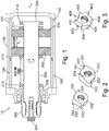
Figure 1 shows an example of an assembly for travel stop adjustment. -
Figure 2 shows an example of the nuts employed in the assembly ofFigure 1 . -
Figure 3 shows a further example of a nut that may be employed in the assembly ofFigure 1 . - Referring to
Figure 1 , there is shown an example of anassembly 10. Theassembly 10 may also be known as an over travel stop unit. Theassembly 10 may include ahousing 100 to house various components that allow for adjustment of the travel stop. As an example shown inFigure 1 , theassembly 10 may have a longitudinal axis A running through the centre of theassembly 10 and thehousing 100 may be provided about this longitudinal axis A. As shown inFigure 1 , there may be provided a shaft, for example, a threadedscrew 200 along the longitudinal axis A of theassembly 10. Afirst nut 201 and asecond nut 202 can be received on the threadedscrew 200. An adjustment gap Ag may be formed between thefirst nut 201 and thesecond nut 202. This may be done manually by an engineer before incorporating the components for theassembly 10 in thehousing 100. - A
first rod 101 may be provided at an inner wall 100' of thehousing 100. Thefirst rod 101 runs parallel to the threadedscrew 200. Asecond rod 102 may be provided at the inner wall 100' of thehousing 100, opposite thefirst rod 101. In the examples shown inFigure 1 , thefirst rod 101 and thesecond rod 102 are cylindrical. Of course, it is envisaged that other geometries could be used as well to allow thefirst nut 201 andsecond nut 202 to engage with thefirst rod 101 andsecond rod 102, as described in more detail below. - As shown in
Figure 1 , the threadedscrew 200 has afirst end 203 and asecond end 204. Provided at thesecond end 204 of the threadedscrew 200 is afirst end stop 214. Provided on one side of thefirst nut 201 is asecond end stop 211 that faces the first end stop 214 (i.e., thesecond end stop 211 is to the right hand side of the first nut 201). Provided at thefirst end 203 of the threadedscrew 200 is athird end stop 213. Provided on one side of thesecond nut 202 is afourth end stop 212 that faces the third end stop 213 (i.e., thefourth end stop 212 is provided on the left hand side of the second nut 202). The gap between thethird end stop 213 and thefourth end stop 212 is designated by the reference Sg and refers to the resultant stroke gap. Before thehousing 100 is applied to an actuator assembly (not shown), a user can adjust the resultant stroke gap Sg by placing thefirst nut 201 andsecond nut 202 at the desired positions on the threadedscrew 200. The user can then engage the threadedscrew 200 in thehousing 100. Anaxial screw 301 is applied to the threadedscrew 200 to maintain the position of the threadedscrew 200 in thehousing 100. There is also provided an adjustment means 300, which may be in the form of an exposed outer spline of the threadedscrew 200. This is described in more detail below. - Referring to
Figure 2 , thefirst nut 201 and thesecond nut 202 are shown. As can be seen inFigure 2 , thefirst nut 201 may include afirst hook 221 that extends radially from the overall surface of thefirst nut 201. Thefirst nut 201 may also include asecond hook 222 that also extends radially from the overall surface of thefirst nut 201. Thefirst hook 221 of thefirst nut 201, therefore, provides a first hook surface 221' that can interact with one of thefirst rod 101 or the second rod 102 (as shown inFigure 1 ), in use. The first hook surface 221' is perpendicular to the overall surface of thefirst nut 201 and is configured to receive one of thefirst rod 101 or the second rod 102 (e.g. it includes a recess (not shown) that is sized and shaped to receive either thefirst rod 101 or the second rod 102). Thesecond hook 222 also may provide a second hook surface 222' that can interact with one of thefirst rod 101 or thesecond rod 102, in use. The second hook surface 222' is perpendicular to the overall surface of thefirst nut 201 and is configured to receive one of thefirst rod 101 or the second rod 102 (e.g. it includes a recess (not shown) that is sized and shaped to receive either thefirst rod 101 or the second rod 102). - As also shown in
Figure 2 , thefirst nut 201 may have afirst protrusion 223 and asecond protrusion 224 that extend radially from the surface of thefirst nut 201 along the longitudinal axis. Thefirst protrusion 223 andsecond protrusion 224 may therefore act as the second end stop 211 shown inFigure 1 . - As can also be seen in
Figure 2 , thesecond nut 202 may include afirst hook 231 that extends radially from the surface of thesecond nut 202. Thesecond nut 202 may also include asecond hook 232 that also extends radially from the surface of thesecond nut 202. Thefirst hook 231 of thesecond nut 202, therefore, provides a first hook surface 231' that can interact with one of thefirst rod 101 or the second rod 102 (as shown inFigure 1 ), in use. The first hook surface 231' is perpendicular to the overall surface of thesecond nut 202 and is configured to receive one of thefirst rod 101 or the second rod 102 (e.g. it includes a recess (not shown) that is sized and shaped to receive either thefirst rod 101 or the second rod 102). Thesecond hook 232 also may provide a second hook surface 232' that can interact with one of thefirst rod 101 or thesecond rod 102, in use. The second hook surface 232' is perpendicular to the overall surface of thesecond nut 202 and is configured to receive one of thefirst rod 101 or the second rod 102 (e.g. it includes a recess (not shown) that is sized and shaped to receive either thefirst rod 101 or the second rod 102). - As also shown in
Figure 2 , thesecond nut 202 may have afirst protrusion 233 and a second protrusion (not shown) that extend radially from the surface of thefirst nut 201 along the longitudinal axis. Thefirst protrusion 233 and second protrusion (not shown) may therefore act as the fourth end stop 212 shown inFigure 1 . - As shown in
Figure 2 , thefirst nut 201 and thesecond nut 202 are arranged such thatprotrusions first nut 201 and thesecond nut 202 are arranged on the threadedscrew 200, they are equal parts inversed along the longitudinal axis. - Referring now to both
Figures 1 and 2 , thefirst nut 201 andsecond nut 202 may be introduced on to the threadedscrew 200 by the user. When the travel stop unit, orassembly 10, is to be fitted to an actuator system, the user may first determine and set the position of thefirst nut 201 and thesecond nut 202 to result in the adjustment gap Ag (i.e., the space between thefirst nut 201 and the second nut 202). Once thefirst nut 201 and thesecond nut 202 have been placed in theassembly 10, the user may then set the resultant stroke gap, Sg, by turning the threadedscrew 200 with the adjustment means 300. As the threadedscrew 200 turns, the first hook surface 221' of thefirst nut 201 may contact one of either thefirst rod 101 or thesecond rod 102. The second hook surface 222' of thefirst nut 201 may then contact the other of either thefirst rod 101 or the second rod 102 (i.e., the rod that is not being contacted by the first hook surface 221' of the first nut 201). Similarly, as the threadedscrew 200 turns, the first hook surface 231' of thesecond nut 202 may also contact either one of thefirst rod 101 or thesecond rod 102. The second hook surface 232' of thesecond nut 202 may then contact the other of either thefirst rod 101 or the second rod 102 (i.e., the rod that is not being contacted by the first hook surface 231' of the second nut 202). - When the first hook surfaces 221' and 231', and the second hook surfaces 222' and 232', of the first and
second nut first rod 101 and thesecond rod 102, thefirst nut 201 and thesecond nut 202 are then set in position, which results in the resultant stroke gap Sg. -
Figure 3 shows analternative nut 400 that could replace thefirst nut 201 andsecond nut 202 described above. In the example shown inFigure 3 , there is provided a nut 400 (which could form thefirst nut 201 and thesecond nut 202 described above) that may include afirst hook 401, asecond hook 402, athird hook 403, afourth hook 404, afifth hook 405 and asixth hook 406. In this way, the user may have smaller turns to engage thefirst rod 101 and thesecond rod 102, which allows for a more accurate adjustment of the resultant stroke gap Sg. It is appreciated that thenut 400, in this example, includes six hooks, but that any number of hooks of more than two could replace the hooks described in relation to thefirst nut 201 andsecond nut 202 inFigure 2 . There may also be provided afirst protrusion 410 on thealternative nut 400 that acts as an end stop in relation to the protrusions described with reference toFigure 2 . - Although the invention has been described in terms of preferred embodiments as set forth above, it should be understood that these embodiments are illustrative only and that the claims are not limited to those embodiments. Those skilled in the art will be able to make modifications and alternatives in view of the disclosure which are contemplated as falling within the scope of the appended claims.
Claims (15)
- A travel stop assembly (10) for an actuator, comprising:a housing (100);a shaft (200) provided along a longitudinal axis (A), the shaft (200) having a first end (203) and a second end (204);a first nut (201) and a second nut (202) provided on the shaft (200), wherein there is provided a first gap (Ag) between the first nut (201) and the second nut (202);a second gap (Sg) provided between the second nut (202) and the first end (203) of the shaft (200);means for adjusting the position of the first nut (201) and the second nut (202) such that the second gap (Sg) is maintained.
- The travel stop assembly of claim 1, wherein the means for adjusting the position of the first nut (201) and the second nut (202) further comprises:a first rod (101) and a second rod (102) provided at an inner wall (100') of the housing (100);wherein the first nut (201) includes a first hook (221) and a second hook (222) that are configured to engage the first rod (101) and the second rod (102); andwherein the second nut (202) includes a first hook (231) and a second hook (232) that are configured to engage the first rod (101) and the second rod (102).
- The travel stop assembly of claim 2, wherein the first rod (101) and second rod (102) are parallel the shaft (200), and wherein the first rod (101) is opposite the second rod (102).
- The travel stop assembly of any preceding claim, further comprising:a first end stop (214) provided at the second end (204) of the shaft (200);a second end stop (211) provided on one side of the first nut (201);a third end stop (213) provided at the first end (203) of the shaft (200);a fourth end stop (212) provided on one side of the second nut (202).
- The travel stop assembly of claim 4, wherein the second gap (Sg) is provided between the third end stop (213) and the fourth end stop (212).
- The travel stop assembly of any of claim 4 or 5, wherein the second end stop (211) comprises at least one protrusion that extends radially away from the surface of the first nut (201) along the longitudinal axis.
- The travel stop assembly of any of claims 4-6, wherein the fourth end stop (212) comprises at least one protrusion that extends radially away from the surface of the second nut (202) along the longitudinal axis.
- The travel stop assembly of any preceding claim, wherein the shaft (200) is a threaded screw.
- An actuator assembly including a travel stop assembly as claimed in any preceding claim.
- A method of adjusting a resultant stroke gap of a travel stop unit, the method comprising:providing a shaft (200) along a longitudinal axis (A), the shaft (200) having a first end (203) and a second end (204);providing a first nut (201) and a second nut (202) on the shaft (200);providing a first gap (Ag) between the first nut (201) and the second nut (202);providing a second gap (Sg) between the second nut (202) and the first end (203) of the shaft (200); andadjusting the position of the first nut (201) and the second nut (202) such that the second gap (Sg) is maintained in a housing (100).
- The method of claim 10, wherein adjusting the position of the first nut (201) and the second nut (202) further comprises:providing a first rod (101) and a second rod (102) at an inner wall (100') of the housing (100), and engaging a first hook (221) and a second hook (222) of the first nut (201) to the first rod (101) and the second rod (102); andengaging a first hook (231) and a second hook (232) of the second nut (202) to the first rod (101) and the second rod (102).
- The method of claim 11, wherein the first rod (101) and second rod (102) are parallel the shaft (200), and wherein the first rod (101) is opposite the second rod (102).
- The method of any of claims 10-12, the method further comprising:providing a first end stop (214) at the second end (204) of the shaft (200);providing a second end stop (211) on one side of the first nut (201);providing a third end stop (213) at the first end (203) of the shaft (200);providing a fourth end stop (212) on one side of the second nut (202).
- The method of claim 13, wherein the second gap (Sg) is provided between the third end stop (213) and the fourth end stop (212).
- The method of claim 13 or 14, wherein the second end stop (211) comprises at least one protrusion that extends radially away from the surface of the first nut (201) along the longitudinal axis, and wherein the fourth end stop (212) comprises at least one protrusion that extends radially away from the surface of the second nut (202) along the longitudinal axis.
Priority Applications (2)
| Application Number | Priority Date | Filing Date | Title |
|---|---|---|---|
| EP20275060.0A EP3882486A1 (en) | 2020-03-20 | 2020-03-20 | Double nut stroke adjustment travel stop |
| US17/205,187 US20210293312A1 (en) | 2020-03-20 | 2021-03-18 | Double nut stroke adjustment travel stop |
Applications Claiming Priority (1)
| Application Number | Priority Date | Filing Date | Title |
|---|---|---|---|
| EP20275060.0A EP3882486A1 (en) | 2020-03-20 | 2020-03-20 | Double nut stroke adjustment travel stop |
Publications (1)
| Publication Number | Publication Date |
|---|---|
| EP3882486A1 true EP3882486A1 (en) | 2021-09-22 |
Family
ID=69953924
Family Applications (1)
| Application Number | Title | Priority Date | Filing Date |
|---|---|---|---|
| EP20275060.0A Pending EP3882486A1 (en) | 2020-03-20 | 2020-03-20 | Double nut stroke adjustment travel stop |
Country Status (2)
| Country | Link |
|---|---|
| US (1) | US20210293312A1 (en) |
| EP (1) | EP3882486A1 (en) |
Cited By (1)
| Publication number | Priority date | Publication date | Assignee | Title |
|---|---|---|---|---|
| EP4239216A1 (en) * | 2022-03-02 | 2023-09-06 | Goodrich Actuation Systems Limited | Actuator overtravel stop assembly and a method of resetting the overtravel stop mechanism of the same |
Families Citing this family (2)
| Publication number | Priority date | Publication date | Assignee | Title |
|---|---|---|---|---|
| US11746862B2 (en) | 2020-12-30 | 2023-09-05 | Cameron International Corporation | Actuator assembly |
| CN118216765B (en) * | 2024-05-27 | 2024-09-17 | 常州市凯迪电器股份有限公司 | A linear drive device and intelligent furniture including the linear drive device |
Citations (3)
| Publication number | Priority date | Publication date | Assignee | Title |
|---|---|---|---|---|
| US3319481A (en) * | 1965-05-24 | 1967-05-16 | Goodman Robert | Adjustable device for translating rotary motion into linear motion |
| US5255882A (en) * | 1990-06-19 | 1993-10-26 | Diehl Gmbh & Co. | Setting device with a nut controllable by a spindle |
| EP3196509A2 (en) * | 2016-01-11 | 2017-07-26 | The Boeing Company | Linear actuator system with circumferentially and axially adjustable end stop assembly |
-
2020
- 2020-03-20 EP EP20275060.0A patent/EP3882486A1/en active Pending
-
2021
- 2021-03-18 US US17/205,187 patent/US20210293312A1/en not_active Abandoned
Patent Citations (3)
| Publication number | Priority date | Publication date | Assignee | Title |
|---|---|---|---|---|
| US3319481A (en) * | 1965-05-24 | 1967-05-16 | Goodman Robert | Adjustable device for translating rotary motion into linear motion |
| US5255882A (en) * | 1990-06-19 | 1993-10-26 | Diehl Gmbh & Co. | Setting device with a nut controllable by a spindle |
| EP3196509A2 (en) * | 2016-01-11 | 2017-07-26 | The Boeing Company | Linear actuator system with circumferentially and axially adjustable end stop assembly |
Cited By (2)
| Publication number | Priority date | Publication date | Assignee | Title |
|---|---|---|---|---|
| EP4239216A1 (en) * | 2022-03-02 | 2023-09-06 | Goodrich Actuation Systems Limited | Actuator overtravel stop assembly and a method of resetting the overtravel stop mechanism of the same |
| US12313149B2 (en) | 2022-03-02 | 2025-05-27 | Goodrich Actuation Systems Limited | Actuator overtravel stop assembly |
Also Published As
| Publication number | Publication date |
|---|---|
| US20210293312A1 (en) | 2021-09-23 |
Similar Documents
| Publication | Publication Date | Title |
|---|---|---|
| US20210293312A1 (en) | Double nut stroke adjustment travel stop | |
| EP2984741B1 (en) | Motor for an egr valve | |
| US10215264B2 (en) | Linear actuator system with circumferentially and axially adjustable end stop assembly | |
| US20140361205A1 (en) | Setting Screw Connection for a Hydraulic Valve, and Hydraulic Valve | |
| US4661031A (en) | Fatigue resistant fastener assembly | |
| US4367672A (en) | Auxiliary power steering, especially for motor vehicles | |
| EP3096052B1 (en) | Relief valve | |
| EP2180197A2 (en) | Special nut | |
| US20100018587A1 (en) | Valve adjustment assembly | |
| US9631646B2 (en) | Cylinder mechanism | |
| WO2013149914A1 (en) | Holder for fastening a component to an internal combustion engine, bearing bush for such a holder, and fuel injection system | |
| EP3538323A1 (en) | Axial swage tool | |
| WO2024088892A1 (en) | Torsional vibration isolated coupling element | |
| GB2136541A (en) | Valve actuator coupling | |
| EP3550179B1 (en) | Actuator piston with adjustable stops and method of adjusting the same | |
| US10781899B2 (en) | Actuator | |
| CN114183524A (en) | Fixed U-shaped plate for solenoid valve group | |
| US20180058590A1 (en) | Regulating valve, valve body, valve stem, and locking member | |
| US7178787B2 (en) | Valve assembly | |
| CN110566691B (en) | Directly controlled hydraulic directional valve | |
| EP3792504A1 (en) | Hydraulic actuator end stroke stop pressure/load control | |
| US10753481B2 (en) | Regulating valve, valve body, and valve stem | |
| JP2009505022A (en) | Packing nut for control valve | |
| EP4629491A1 (en) | Control system | |
| JPH0217382B2 (en) |
Legal Events
| Date | Code | Title | Description |
|---|---|---|---|
| PUAI | Public reference made under article 153(3) epc to a published international application that has entered the european phase |
Free format text: ORIGINAL CODE: 0009012 |
|
| STAA | Information on the status of an ep patent application or granted ep patent |
Free format text: STATUS: THE APPLICATION HAS BEEN PUBLISHED |
|
| AK | Designated contracting states |
Kind code of ref document: A1 Designated state(s): AL AT BE BG CH CY CZ DE DK EE ES FI FR GB GR HR HU IE IS IT LI LT LU LV MC MK MT NL NO PL PT RO RS SE SI SK SM TR |
|
| STAA | Information on the status of an ep patent application or granted ep patent |
Free format text: STATUS: REQUEST FOR EXAMINATION WAS MADE |
|
| 17P | Request for examination filed |
Effective date: 20220322 |
|
| RBV | Designated contracting states (corrected) |
Designated state(s): AL AT BE BG CH CY CZ DE DK EE ES FI FR GB GR HR HU IE IS IT LI LT LU LV MC MK MT NL NO PL PT RO RS SE SI SK SM TR |
|
| STAA | Information on the status of an ep patent application or granted ep patent |
Free format text: STATUS: EXAMINATION IS IN PROGRESS |
|
| 17Q | First examination report despatched |
Effective date: 20230412 |
|
| GRAP | Despatch of communication of intention to grant a patent |
Free format text: ORIGINAL CODE: EPIDOSNIGR1 |
|
| STAA | Information on the status of an ep patent application or granted ep patent |
Free format text: STATUS: GRANT OF PATENT IS INTENDED |
|
| INTG | Intention to grant announced |
Effective date: 20251215 |
|
| GRAJ | Information related to disapproval of communication of intention to grant by the applicant or resumption of examination proceedings by the epo deleted |
Free format text: ORIGINAL CODE: EPIDOSDIGR1 |
|
| STAA | Information on the status of an ep patent application or granted ep patent |
Free format text: STATUS: EXAMINATION IS IN PROGRESS |
|
| GRAP | Despatch of communication of intention to grant a patent |
Free format text: ORIGINAL CODE: EPIDOSNIGR1 |
|
| INTC | Intention to grant announced (deleted) | ||
| STAA | Information on the status of an ep patent application or granted ep patent |
Free format text: STATUS: GRANT OF PATENT IS INTENDED |
|
| INTG | Intention to grant announced |
Effective date: 20260401 |
|
| GRAS | Grant fee paid |
Free format text: ORIGINAL CODE: EPIDOSNIGR3 |
|
| GRAA | (expected) grant |
Free format text: ORIGINAL CODE: 0009210 |
|
| STAA | Information on the status of an ep patent application or granted ep patent |
Free format text: STATUS: THE PATENT HAS BEEN GRANTED |