EP3882225A1 - Damaging process device and method for cleavage site used for cutting medical glass product - Google Patents
Damaging process device and method for cleavage site used for cutting medical glass product Download PDFInfo
- Publication number
- EP3882225A1 EP3882225A1 EP19900981.2A EP19900981A EP3882225A1 EP 3882225 A1 EP3882225 A1 EP 3882225A1 EP 19900981 A EP19900981 A EP 19900981A EP 3882225 A1 EP3882225 A1 EP 3882225A1
- Authority
- EP
- European Patent Office
- Prior art keywords
- glass product
- medical
- glass
- medical glass
- laser beam
- Prior art date
- Legal status (The legal status is an assumption and is not a legal conclusion. Google has not performed a legal analysis and makes no representation as to the accuracy of the status listed.)
- Withdrawn
Links
Images





Classifications
-
- C—CHEMISTRY; METALLURGY
- C03—GLASS; MINERAL OR SLAG WOOL
- C03B—MANUFACTURE, SHAPING, OR SUPPLEMENTARY PROCESSES
- C03B33/00—Severing cooled glass
- C03B33/09—Severing cooled glass by thermal shock
- C03B33/095—Tubes, rods or hollow products
- C03B33/0955—Tubes, rods or hollow products using a focussed radiation beam, e.g. laser
-
- C—CHEMISTRY; METALLURGY
- C03—GLASS; MINERAL OR SLAG WOOL
- C03C—CHEMICAL COMPOSITION OF GLASSES, GLAZES OR VITREOUS ENAMELS; SURFACE TREATMENT OF GLASS; SURFACE TREATMENT OF FIBRES OR FILAMENTS MADE FROM GLASS, MINERALS OR SLAGS; JOINING GLASS TO GLASS OR OTHER MATERIALS
- C03C23/00—Other surface treatment of glass not in the form of fibres or filaments
- C03C23/0005—Other surface treatment of glass not in the form of fibres or filaments by irradiation
- C03C23/0025—Other surface treatment of glass not in the form of fibres or filaments by irradiation by a laser beam
-
- B—PERFORMING OPERATIONS; TRANSPORTING
- B23—MACHINE TOOLS; METAL-WORKING NOT OTHERWISE PROVIDED FOR
- B23K—SOLDERING OR UNSOLDERING; WELDING; CLADDING OR PLATING BY SOLDERING OR WELDING; CUTTING BY APPLYING HEAT LOCALLY, e.g. FLAME CUTTING; WORKING BY LASER BEAM
- B23K26/00—Working by laser beam, e.g. welding, cutting or boring
- B23K26/02—Positioning or observing the workpiece, e.g. with respect to the point of impact; Aligning, aiming or focusing the laser beam
- B23K26/03—Observing, e.g. monitoring, the workpiece
- B23K26/032—Observing, e.g. monitoring, the workpiece using optical means
-
- B—PERFORMING OPERATIONS; TRANSPORTING
- B23—MACHINE TOOLS; METAL-WORKING NOT OTHERWISE PROVIDED FOR
- B23K—SOLDERING OR UNSOLDERING; WELDING; CLADDING OR PLATING BY SOLDERING OR WELDING; CUTTING BY APPLYING HEAT LOCALLY, e.g. FLAME CUTTING; WORKING BY LASER BEAM
- B23K26/00—Working by laser beam, e.g. welding, cutting or boring
- B23K26/02—Positioning or observing the workpiece, e.g. with respect to the point of impact; Aligning, aiming or focusing the laser beam
- B23K26/06—Shaping the laser beam, e.g. by masks or multi-focusing
- B23K26/062—Shaping the laser beam, e.g. by masks or multi-focusing by direct control of the laser beam
- B23K26/0622—Shaping the laser beam, e.g. by masks or multi-focusing by direct control of the laser beam by shaping pulses
- B23K26/0624—Shaping the laser beam, e.g. by masks or multi-focusing by direct control of the laser beam by shaping pulses using ultrashort pulses, i.e. pulses of 1 ns or less
-
- B—PERFORMING OPERATIONS; TRANSPORTING
- B23—MACHINE TOOLS; METAL-WORKING NOT OTHERWISE PROVIDED FOR
- B23K—SOLDERING OR UNSOLDERING; WELDING; CLADDING OR PLATING BY SOLDERING OR WELDING; CUTTING BY APPLYING HEAT LOCALLY, e.g. FLAME CUTTING; WORKING BY LASER BEAM
- B23K26/00—Working by laser beam, e.g. welding, cutting or boring
- B23K26/50—Working by transmitting the laser beam through or within the workpiece
- B23K26/53—Working by transmitting the laser beam through or within the workpiece for modifying or reforming the material inside the workpiece, e.g. for producing break initiation cracks
-
- C—CHEMISTRY; METALLURGY
- C03—GLASS; MINERAL OR SLAG WOOL
- C03B—MANUFACTURE, SHAPING, OR SUPPLEMENTARY PROCESSES
- C03B33/00—Severing cooled glass
- C03B33/06—Cutting or splitting glass tubes, rods, or hollow products
-
- B—PERFORMING OPERATIONS; TRANSPORTING
- B23—MACHINE TOOLS; METAL-WORKING NOT OTHERWISE PROVIDED FOR
- B23K—SOLDERING OR UNSOLDERING; WELDING; CLADDING OR PLATING BY SOLDERING OR WELDING; CUTTING BY APPLYING HEAT LOCALLY, e.g. FLAME CUTTING; WORKING BY LASER BEAM
- B23K2103/00—Materials to be soldered, welded or cut
- B23K2103/50—Inorganic materials other than metals or composite materials
- B23K2103/54—Glass
-
- C—CHEMISTRY; METALLURGY
- C03—GLASS; MINERAL OR SLAG WOOL
- C03B—MANUFACTURE, SHAPING, OR SUPPLEMENTARY PROCESSES
- C03B33/00—Severing cooled glass
- C03B33/02—Cutting or splitting sheet glass or ribbons; Apparatus or machines therefor
- C03B33/0222—Scoring using a focussed radiation beam, e.g. laser
-
- Y—GENERAL TAGGING OF NEW TECHNOLOGICAL DEVELOPMENTS; GENERAL TAGGING OF CROSS-SECTIONAL TECHNOLOGIES SPANNING OVER SEVERAL SECTIONS OF THE IPC; TECHNICAL SUBJECTS COVERED BY FORMER USPC CROSS-REFERENCE ART COLLECTIONS [XRACs] AND DIGESTS
- Y02—TECHNOLOGIES OR APPLICATIONS FOR MITIGATION OR ADAPTATION AGAINST CLIMATE CHANGE
- Y02P—CLIMATE CHANGE MITIGATION TECHNOLOGIES IN THE PRODUCTION OR PROCESSING OF GOODS
- Y02P40/00—Technologies relating to the processing of minerals
- Y02P40/50—Glass production, e.g. reusing waste heat during processing or shaping
- Y02P40/57—Improving the yield, e-g- reduction of reject rates
Definitions
- the present invention relates to an apparatus and a method for damaging a cutting part of a medical glass product, and more specifically, to an apparatus and a method for damaging a cutting part of a medical glass product, for example, an ampoule using glass as a material or a glass tube for a medical device, by using an Ultrafast Laser to minimize the generation of glass fragments.
- the present invention relates to a method for damaging a cutting part such as a medical glass product, for example, a glass ampoule for storing an injection solution or a nutritional supplement, or a medical glass tube.
- a cutting part such as a medical glass product, for example, a glass ampoule for storing an injection solution or a nutritional supplement, or a medical glass tube.
- Medical glass products such as glass ampoules for storing injectables or nutritional supplements, are made in such a way that the contents of the injectables and nutritional supplements can enter the human body. Therefore, it is essential to make them completely sterile/dust-free in the process of breaking apart the glass container or tube during use. Therefore, careful attention and considerable attention are required in the manufacturing process.
- an OPC ampoule used as a container for an injection or nutritional supplement is an ampoule designed to minimize the generation of glass fragments, but even with normal use, fine glass fragments will be generated when the user forces the ampoule by hand.
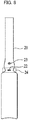
- the prior art or nutritional supplement ampoule 20 includes a cutting direction indicator 23, a cutting aid notch 22, and a bottleneck 24.
- the conventional ampoule 20 for injection or nutritional supplement has the cutting aid notch 22 formed at the cutting part of the neck (bottleneck 24) of the ampoule by the diamond blade rotating at high speed.
- a bottleneck portion having a cut part smaller in diameter than the periphery is provided, and a user cuts the ampoule by hand by applying pressure to a portion displayed on the cutting direction indicator 23.
- the cutting aid notch 22 is then folded open so that an injection or nutritional supplement within the ampoule can be used.
- FIGS. 9A and 9B are photographs of a cut part of a glass ampoule taken at a high speed when a user manually opens the glass ampoule in which the cutting aid notch 22 is formed by a conventional technique.
- FIG. 9A it is seen that glass dust is scattered even though the glass ampoule is normally opened.
- FIG. 9B it is seen that a large glass fragment is generated.
- fine glass powder produced when a user (For example, a nurse) cuts the cut part of the ampoule for injection or drinking with an injection solution or a nutritional supplement put in the OPC ampoule can enter the ampoule.
- the generation of glass fragments can be significantly increased when not used properly (For example, when a user applies a force in a direction different from the direction displayed on the cutting direction indicator 23). That is, although the OPC ampoule 20 is made so as to provide directionality so as not to generate fragments when the glass is cut, if a force is applied in a different direction without applying a force in the indicated direction, more glass fragments are generated.
- another object of the present invention is to provide a method for producing an ampoule for injection or a nutritional supplement, which is produced as described above, and hardly generates particles even when the ampoule for injection or nutritional supplement is cut in any direction, even if the cutting direction is not indicated on the ampoule, and to provide the ampoule for injection.
- Still another object of the present invention is to provide a method for producing an ampoule for an injection or a nutritional supplement, which can significantly reduce the process time and defects required for producing a bottleneck without the need to produce a bottleneck portion when producing an ampoule for an injection or a nutritional supplement, and to provide an ampoule for an injection or a nutritional supplement.
- the cutting part damage apparatus of the medical glass product provides a laser light source for bursting an ultra-fast laser beam.; a beam profile forming section such that the ultra-fast laser beam has a plurality of focal lengths and is shaped to have an elongated profile; a beam irradiation section irradiates the glass of the medical glass product so that the profile of the shaped ultra-fast laser beam is formed inside the glass of the medical glass product to form inside damage formed by internal defects due to bulk deformation inside the glass of the medical glass product; and a rotating section for rotating the medical glass product at a predetermined rotational speed.
- the cutting part damage apparatus of the medical glass product can further include a control unit for controlling the predetermined rotation speed and the burst speed of the laser beam so that a plurality of inside damages are formed at the cutting part of the medical glass product.
- the inside damage can be formed in the thickness direction of the glass along the circumference of the medical glass product.
- the medical glass product may also include any one of ampoules for injection or nutritional supplements, blood collection tubes, syringes, cartridges, glass medicine bottles, and glass tubes for medical devices.
- a cutting error can be reduced when the ampoule is used. That is, even if the cutting direction is not displayed on the ampoule, since there is hardly any generation of particles even if the ampoule is cut in any direction, the cutting error in using the ampoule can be remarkably reduced.
- FIG. 1 is a block diagram of a cutting part damage apparatus 1000 for a medical glass product according to an embodiment of the present invention.
- the cutting part damage apparatus of the glass product may include a control section 100, a laser light source 200, an energy control module 300, a beam expander 400, a beam profile forming section 500, a beam irradiation section 600, a rotating section 700, and a distance adjusting section 800.
- the medical glass product means a medical glass product which has a cut surface processed with glass while including a portion in the form of a tube, such as an ampoule for injection or a nutritional supplement, a blood collection tube, a syringe, a cartridge, a glass medicine bottle, etc., and which should not contain glass fragments or glass dust inside.
- a tube such as an ampoule for injection or a nutritional supplement, a blood collection tube, a syringe, a cartridge, a glass medicine bottle, etc., and which should not contain glass fragments or glass dust inside.
- soda lime, quartz, borosilicate glass and the like are used as the material of the glass product. Particularly in the case of a medical glass container, borosilicate glass is preferable.
- the control section 100 can control the energy of a laser beam 150, the distance between the workpiece (medical glass product) 10 and the beam irradiation section 600, and the rotational speed of the rotating section 700.
- the magnification can be adjusted through control for adjusting the distance between a first condenser lens 630 and a second condenser lens 650.
- the control section 100 can control the burst number of the laser beam 150 according to the rotational speed of the rotating section 700.
- the laser light source 200 generates and irradiates an ultra-fast laser beam 150.
- the energy control module 300 and the beam expander 400 are configured to adjust the energy amount and the size of the laser beam reaching the workpiece 10.
- an optical mechanism such as a plurality of mirrors 410 may be further provided to allow the laser beam generated by the laser light source to reach the beam profile forming section 500 and the beam irradiation section 600.
- the beam profile forming section 500 is configured to form a profile of a laser beam having a plurality of focal lengths by self-diffraction of an axicon lens, and preferably, an axicon lens is used.
- a laser beam which becomes a plurality of focal lengths by self-diffraction of an axicon lens is generally formed through interference of a laser beam which has passed through a conical lens, e.g., an axicon lens 500.
- the wave front of the laser beam is formed by diffraction of the Gaussian beam passing through the axicon lens.
- Interference fringes are long and consist of central cores of microunit diameter and a number of rings surrounding these cores with relatively low intensity. That is, according to an embodiment of the present invention, the beam profile forming section 500 is shaped such that the ultra-fast laser beam has a plurality of focal lengths and a high aspect ratio profile of an elongated form.
- the laser beam is partially absorbed while passing through the glass of the workpiece 10 to transmit energy to the constituent molecules of the glass, and at this time, the absorbed energy density is high and plasma is instantaneously formed inside the glass of the workpiece 10.
- the plasma described above will cause internal defects due to high aspect ratio bulk deformation to form within the glass of workpiece 10.
- the internal defect formed by the laser beam is referred to herein as damage
- the process for forming damage is referred to as damage processing
- the structure for assisting the cutting of the medical glass product by forming damage is referred to as inside damage 15 (Inside damage, see FIGS. 3 and 6 ).
- a process of continuously forming damage with a laser beam is utilized to form a structure that replaces a cutting aid notch with a prior art diamond blade.
- methods and apparatus for cutting medical glass products by inside damage formation are also within the scope of the present invention.
- the central core radius (r) of the laser beam having a plurality of focal lengths by the self-diffraction of the axicon lens can be expressed by the following equation 1 (The part shown in FIG. 2 is the diameter, indicated by 2r.). r ⁇ 2.4 ⁇ 2 ⁇ sin ⁇ 2 where ⁇ is the angle between two diffracted wave vectors formed by the axicon lens (See FIG. 2 ). Such an angle is determined by the axicon parameter (For example, the axicon parameter includes the angle of the vertex of the axicon lens and the optical index of refraction).
- the length (L) of the laser beam which becomes to have a plurality of focal lengths by self-diffraction of an axicon lens called depth of focus from a geometrical point of view can be calculated by the following equation 2.
- L ⁇ w 2 tan ⁇ 2 where w is the diameter of the laser beam 150 incident on the axicon lens.
- the shape of the laser beam which becomes multi-focal length by self-diffraction of the axicon lens, is designed to elongate along the thickness of the glass and to produce uniform inside damage.
- elongated means a case where the length (L) of the inside damage to be processed into the glass of the workpiece 10 is very large than the radius (R) of the inside damage, and the length (L) of the inside damage is 10 times or more the radius (R) of the inside damage.
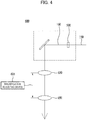
- the beam irradiation section 600 can include optical mechanisms 630, 650 for allowing a laser beam deformed to have an elongated profile at the beam profile forming section 500 to be incident on the glass portion of the workpiece 10, a coaxial CCD camera 610 for confirming accurate incidence, and an episcopic illumination 620. Beam splitters 640 and 660 may then be included to align the coaxial CCD camera 610 and the episcopic illumination 620 with a laser beam 160.
- the beam irradiation section 600 can control the laser beam so as to form locally concentrated energy in the glass material of the workpiece 10 including the first condenser lens 630, the second condenser lens 650 and the magnification adjusting device 635 (See FIG. 4 ).
- the deformed laser beam 160 is imaged to cause bulk deformation at a reduced rate through the first condenser lens 630 and the second condenser lens 650.
- the wavelength of the laser beam used in this embodiment is in the range of 1030 ⁇ 1070 nm, and the focal position is such that the starting point of the laser beam, which becomes to have a plurality of focal lengths by the self-diffraction of the axicon lens, can be formed inside the glass product in the thickness direction of the glass from the glass surface of the workpiece.
- the rotating section 700 is configured to rotate the workpiece 10 in order to form the inside damage 15 in the thickness direction of the glass along the circumference of the workpiece 10.
- the thickness direction of the glass means a direction perpendicular to the glass surface of the workpiece 10 (See direction A in FIG. 5 ).
- the control section 100 determines the interval between the inside damage depending on the rotation speed and the burst time of the laser beam.
- the control section 100 can control the energy of the laser beam provided in the thickness direction of the glass by controlling the burst numbers.
- the burst number means the number of pulses included in one burst.
- the distance adjusting section 800 adjusts the distance between the workpiece 10 and the beam irradiation section 600 so that the laser beam having a plurality of focal lengths by the self-diffraction of the axicon lens can be accurately imaged inside the glass of the workpiece 10.
- FIGS. 6A to 6C are diagrams for explaining the inside damage formed in the circumferential direction while rotating the workpiece 10 by the rotating section 700.
- FIG. 6A is a view showing a part of the workpiece 10
- FIG. 6B is a view showing a cross section of the B-B' portion of FIG. 6A
- FIG. 6C is a view in which the inside damage 15 of FIG. 6B is actually embodied and photographed.
- the inside damage 15 is formed in the thickness direction of the glass along the circumferential surface of the cut part of the workpiece 10, for example, the injection ampoule, by the laser beam having a plurality of focal lengths by the self-diffraction of the axicon lens formed by the beam profile forming section 500.
- FIGS. 7A and 7B are diagrams for explaining an embodiment and an effect according to an embodiment of the present invention.
- FIGS. 7A and 7B while the injection ampoule was rotated as the workpiece 10, inside damage having a diameter of 2 ⁇ 4 ⁇ m was formed.
- the length (L) of the laser beam having a plurality of focal lengths by the self-diffraction of the axicon lens was processed to approximately the thickness of the glass.
- the circumference of the ampoule was about 4 mm
- the laser used had a wavelength of 1030 nm to 1070 nm
- the pulse energy was embodied as 80 uJ or greater.
- the ultra-fast laser beam was burst at a speed of 1000 Khz or more.
- a completely dust-free medical glass product process is provided by removing a source of foreign matter flowing into the ampoule during the manufacturing process of the medical glass product.
- a cutting error can be reduced when the ampoule is used. That is, even if the cutting direction is not displayed on the ampoule, since there is hardly any generation of particles even if the ampoule is cut in any direction, the cutting error in using the ampoule can be remarkably reduced.
Landscapes
- Engineering & Computer Science (AREA)
- Physics & Mathematics (AREA)
- Optics & Photonics (AREA)
- Chemical & Material Sciences (AREA)
- Plasma & Fusion (AREA)
- Mechanical Engineering (AREA)
- Organic Chemistry (AREA)
- Chemical Kinetics & Catalysis (AREA)
- General Chemical & Material Sciences (AREA)
- Materials Engineering (AREA)
- Oil, Petroleum & Natural Gas (AREA)
- Health & Medical Sciences (AREA)
- Toxicology (AREA)
- Thermal Sciences (AREA)
- Life Sciences & Earth Sciences (AREA)
- Geochemistry & Mineralogy (AREA)
- Re-Forming, After-Treatment, Cutting And Transporting Of Glass Products (AREA)
- Laser Beam Processing (AREA)
- Medical Preparation Storing Or Oral Administration Devices (AREA)
- Surface Treatment Of Glass (AREA)
Abstract
Description
- The present invention relates to an apparatus and a method for damaging a cutting part of a medical glass product, and more specifically, to an apparatus and a method for damaging a cutting part of a medical glass product, for example, an ampoule using glass as a material or a glass tube for a medical device, by using an Ultrafast Laser to minimize the generation of glass fragments.
- The present invention relates to a method for damaging a cutting part such as a medical glass product, for example, a glass ampoule for storing an injection solution or a nutritional supplement, or a medical glass tube.
- Medical glass products, such as glass ampoules for storing injectables or nutritional supplements, are made in such a way that the contents of the injectables and nutritional supplements can enter the human body. Therefore, it is essential to make them completely sterile/dust-free in the process of breaking apart the glass container or tube during use. Therefore, careful attention and considerable attention are required in the manufacturing process.
- However, in the manufacturing process of conventional medical glass products, there is always a possibility that foreign substances such as glass fragments enter the ampoule. For example, an OPC ampoule used as a container for an injection or nutritional supplement is an ampoule designed to minimize the generation of glass fragments, but even with normal use, fine glass fragments will be generated when the user forces the ampoule by hand.
- For example, with reference to
FIG. 8 , which shows a prior art injectable ornutritional supplement ampoule 20, the prior art ornutritional supplement ampoule 20 includes acutting direction indicator 23, acutting aid notch 22, and abottleneck 24. - In this case, the
conventional ampoule 20 for injection or nutritional supplement has thecutting aid notch 22 formed at the cutting part of the neck (bottleneck 24) of the ampoule by the diamond blade rotating at high speed. In order to facilitate cutting, a bottleneck portion having a cut part smaller in diameter than the periphery is provided, and a user cuts the ampoule by hand by applying pressure to a portion displayed on thecutting direction indicator 23. Thecutting aid notch 22 is then folded open so that an injection or nutritional supplement within the ampoule can be used. -
FIGS. 9A and 9B are photographs of a cut part of a glass ampoule taken at a high speed when a user manually opens the glass ampoule in which thecutting aid notch 22 is formed by a conventional technique. InFIG. 9A , it is seen that glass dust is scattered even though the glass ampoule is normally opened. Further, referring toFIG. 9B , it is seen that a large glass fragment is generated. - At this time, fine glass powder produced when a user (For example, a nurse) cuts the cut part of the ampoule for injection or drinking with an injection solution or a nutritional supplement put in the OPC ampoule can enter the ampoule.
- In order to solve the problem that fine glass dust can be generated when a notch for assisting cutting is processed through a diamond blade, a method for generating fine gaps by a laser (
Japanese Unexamined Patent Application Publication No. H11 -71124 - Thus, the generation of glass fragments can be significantly increased when not used properly (For example, when a user applies a force in a direction different from the direction displayed on the cutting direction indicator 23). That is, although the
OPC ampoule 20 is made so as to provide directionality so as not to generate fragments when the glass is cut, if a force is applied in a different direction without applying a force in the indicated direction, more glass fragments are generated. - Since such glass fragments and glass powder can cause serious damage to the human body if they enter the human body, in particular, users of the injection solution do not use all the injection solution but use the injection solution except for the part where the glass powder sinks.
- Accordingly, there is an urgent need for a method of manufacturing a medical glass product that can prevent waste of such medical drugs or nutritional supplements, eliminate the possibility of foreign matter flowing into the ampoule, and provide a completely dust-free medical glass product process in order to remove glass fragments and dust harmful to the human body.
- [PTL1]
Japanese Unexamined Patent Application Publication No. H11-71124 - To provide a completely dust-free medical glass product damage processing process by removing a source from which foreign matter flows into an ampule during the manufacturing process of the medical glass product.
- Therefore, according to the present invention, there is provided a method for processing a medical glass product in which generation of particles is minimized during cutting.
- On the other hand, another object of the present invention is to provide a method for producing an ampoule for injection or a nutritional supplement, which is produced as described above, and hardly generates particles even when the ampoule for injection or nutritional supplement is cut in any direction, even if the cutting direction is not indicated on the ampoule, and to provide the ampoule for injection.
- Still another object of the present invention is to provide a method for producing an ampoule for an injection or a nutritional supplement, which can significantly reduce the process time and defects required for producing a bottleneck without the need to produce a bottleneck portion when producing an ampoule for an injection or a nutritional supplement, and to provide an ampoule for an injection or a nutritional supplement.
- In order to solve the above-described problems, the cutting part damage apparatus of the medical glass product according to one embodiment of the present disclosure provides a laser light source for bursting an ultra-fast laser beam.; a beam profile forming section such that the ultra-fast laser beam has a plurality of focal lengths and is shaped to have an elongated profile; a beam irradiation section irradiates the glass of the medical glass product so that the profile of the shaped ultra-fast laser beam is formed inside the glass of the medical glass product to form inside damage formed by internal defects due to bulk deformation inside the glass of the medical glass product; and a rotating section for rotating the medical glass product at a predetermined rotational speed.
- At this time, the cutting part damage apparatus of the medical glass product can further include a control unit for controlling the predetermined rotation speed and the burst speed of the laser beam so that a plurality of inside damages are formed at the cutting part of the medical glass product.
- The inside damage can be formed in the thickness direction of the glass along the circumference of the medical glass product.
- The medical glass product may also include any one of ampoules for injection or nutritional supplements, blood collection tubes, syringes, cartridges, glass medicine bottles, and glass tubes for medical devices.
- Therefore, according to the present invention, there can be provided a method for processing a medical glass product in which generation of particles is minimized during cutting.
- On the other hand, in the case of the ampoule for injection according to the embodiment of the present invention, a cutting error can be reduced when the ampoule is used. That is, even if the cutting direction is not displayed on the ampoule, since there is hardly any generation of particles even if the ampoule is cut in any direction, the cutting error in using the ampoule can be remarkably reduced.
- Further, in the manufacture of the ampoule for injection, since it is not necessary to manufacture the bottleneck part by adding a process, the process time and defects required for manufacturing the bottleneck are remarkably reduced.
- The effects of the present invention are not limited to those exemplified above, and various effects are included herein.
-
-
FIG. 1 is a block diagram of a cutting part damage apparatus for a medical glass product according to an embodiment of the present invention. -
FIG. 2 is a view (part 1) for explaining a laser beam which has a plurality of focal lengths by self-diffraction of an axicon lens according to an embodiment of the present invention. -
FIG. 3 is a diagram (part 2) for explaining a laser beam which has a plurality of focal lengths by self-diffraction of an axicon lens according to an embodiment of the present invention. -
FIG. 4 is a view (part 3) for describing a laser beam having a plurality of focal lengths by self-diffraction of an axicon lens according to an embodiment of the present invention. -
FIG. 5 illustrates the glass thickness direction of an ampoule of the medical glass product according to an embodiment of the present invention. -
FIG. 6A to 6C are a diagrams illustrating the medical glass product produced according to an embodiment of the present invention. -
FIG. 7A and 7B are diagrams illustrating a medical glass product produced according to an embodiment of the present invention. -
FIG. 8 shows a prior art ampoule for injection or nutritional supplement. -
FIG 9A is a high speed photograph at open of an ampoule made by the prior art. -
FIG. 9B shows a high speed photograph at open of an ampoule made by the prior art. - The following content merely exemplifies the principle of the invention. Therefore, those skilled in the art, although not expressly described or illustrated herein, can invent various devices that embody the principles of the invention and are within the concepts and scope of the invention. It should also be understood that, in principle, all conditional terms and examples listed herein are expressly intended only for the purpose of enabling the concept of the invention to be understood and are not limited to such specifically enumerated examples and states.
- Also, in the following description, it should be understood that the preface expressions such as the first, second, and the like are used to describe mutually equivalent and independent objects, and that there is no meaning in the order of main/sub or master/slave.
- The foregoing objects, features and advantages will become more apparent through the following detailed description in connection with the accompanying drawings, whereby a person with ordinary knowledge in the field of the art to which the invention pertains can readily practice the technical ideas of the invention.
- The respective features of the various embodiments of the invention may be coupled or combined with each other in part or in whole, may be technically interlocked and driven in a variety of ways to be fully understood by those skilled in the art, may be practiced independently of each other, and may be practiced together in related relationships.
- Various embodiments of the present invention will now be described in detail with reference to the accompanying drawings.
-
FIG. 1 is a block diagram of a cuttingpart damage apparatus 1000 for a medical glass product according to an embodiment of the present invention. According toFIG. 1 , the cutting part damage apparatus of the glass product may include acontrol section 100, alaser light source 200, anenergy control module 300, abeam expander 400, a beamprofile forming section 500, abeam irradiation section 600, arotating section 700, and adistance adjusting section 800. Here, the medical glass product means a medical glass product which has a cut surface processed with glass while including a portion in the form of a tube, such as an ampoule for injection or a nutritional supplement, a blood collection tube, a syringe, a cartridge, a glass medicine bottle, etc., and which should not contain glass fragments or glass dust inside. - As the material of the glass product, soda lime, quartz, borosilicate glass and the like are used. Particularly in the case of a medical glass container, borosilicate glass is preferable.
- The
control section 100 can control the energy of alaser beam 150, the distance between the workpiece (medical glass product) 10 and thebeam irradiation section 600, and the rotational speed of therotating section 700. The magnification can be adjusted through control for adjusting the distance between afirst condenser lens 630 and asecond condenser lens 650. Thecontrol section 100 can control the burst number of thelaser beam 150 according to the rotational speed of therotating section 700. - The
laser light source 200 generates and irradiates anultra-fast laser beam 150. - The
energy control module 300 and thebeam expander 400, are configured to adjust the energy amount and the size of the laser beam reaching theworkpiece 10. In this case, an optical mechanism such as a plurality ofmirrors 410 may be further provided to allow the laser beam generated by the laser light source to reach the beamprofile forming section 500 and thebeam irradiation section 600. - The beam
profile forming section 500 is configured to form a profile of a laser beam having a plurality of focal lengths by self-diffraction of an axicon lens, and preferably, an axicon lens is used. - As shown in
FIG. 2 , a laser beam which becomes a plurality of focal lengths by self-diffraction of an axicon lens is generally formed through interference of a laser beam which has passed through a conical lens, e.g., anaxicon lens 500. At this time, the wave front of the laser beam is formed by diffraction of the Gaussian beam passing through the axicon lens. Interference fringes are long and consist of central cores of microunit diameter and a number of rings surrounding these cores with relatively low intensity. That is, according to an embodiment of the present invention, the beamprofile forming section 500 is shaped such that the ultra-fast laser beam has a plurality of focal lengths and a high aspect ratio profile of an elongated form. - In this case, the laser beam is partially absorbed while passing through the glass of the
workpiece 10 to transmit energy to the constituent molecules of the glass, and at this time, the absorbed energy density is high and plasma is instantaneously formed inside the glass of theworkpiece 10. Referring toFIG. 3 , the plasma described above will cause internal defects due to high aspect ratio bulk deformation to form within the glass ofworkpiece 10. The internal defect formed by the laser beam is referred to herein as damage, the process for forming damage is referred to as damage processing, and the structure for assisting the cutting of the medical glass product by forming damage is referred to as inside damage 15 (Inside damage, seeFIGS. 3 and6 ). - In embodiments of the present invention, a process of continuously forming damage with a laser beam is utilized to form a structure that replaces a cutting aid notch with a prior art diamond blade. In addition, methods and apparatus for cutting medical glass products by inside damage formation are also within the scope of the present invention.
- In this case, the central core radius (r) of the laser beam having a plurality of focal lengths by the self-diffraction of the axicon lens can be expressed by the following equation 1 (The part shown in
FIG. 2 is the diameter, indicated by 2r.).
where θ is the angle between two diffracted wave vectors formed by the axicon lens (SeeFIG. 2 ). Such an angle is determined by the axicon parameter (For example, the axicon parameter includes the angle of the vertex of the axicon lens and the optical index of refraction). Further, the length (L) of the laser beam which becomes to have a plurality of focal lengths by self-diffraction of an axicon lens called depth of focus from a geometrical point of view can be calculated by the following equation 2.
where w is the diameter of thelaser beam 150 incident on the axicon lens. - In this case, the shape of the laser beam, which becomes multi-focal length by self-diffraction of the axicon lens, is designed to elongate along the thickness of the glass and to produce uniform inside damage. Here, the term "elongated " means a case where the length (L) of the inside damage to be processed into the glass of the
workpiece 10 is very large than the radius (R) of the inside damage, and the length (L) of the inside damage is 10 times or more the radius (R) of the inside damage. - The
beam irradiation section 600 can includeoptical mechanisms profile forming section 500 to be incident on the glass portion of theworkpiece 10, acoaxial CCD camera 610 for confirming accurate incidence, and anepiscopic illumination 620.Beam splitters coaxial CCD camera 610 and theepiscopic illumination 620 with alaser beam 160. - In this case, the
beam irradiation section 600 can control the laser beam so as to form locally concentrated energy in the glass material of theworkpiece 10 including thefirst condenser lens 630, thesecond condenser lens 650 and the magnification adjusting device 635 (SeeFIG. 4 ). Thus, thedeformed laser beam 160 is imaged to cause bulk deformation at a reduced rate through thefirst condenser lens 630 and thesecond condenser lens 650. - The wavelength of the laser beam used in this embodiment is in the range of 1030 ∼ 1070 nm, and the focal position is such that the starting point of the laser beam, which becomes to have a plurality of focal lengths by the self-diffraction of the axicon lens, can be formed inside the glass product in the thickness direction of the glass from the glass surface of the workpiece.
- On the other hand, the
rotating section 700 is configured to rotate theworkpiece 10 in order to form theinside damage 15 in the thickness direction of the glass along the circumference of theworkpiece 10. In this case, the thickness direction of the glass means a direction perpendicular to the glass surface of the workpiece 10 (See direction A inFIG. 5 ). In this case, thecontrol section 100 determines the interval between the inside damage depending on the rotation speed and the burst time of the laser beam. Thecontrol section 100 can control the energy of the laser beam provided in the thickness direction of the glass by controlling the burst numbers. The burst number means the number of pulses included in one burst. - On the other hand, the
distance adjusting section 800 adjusts the distance between the workpiece 10 and thebeam irradiation section 600 so that the laser beam having a plurality of focal lengths by the self-diffraction of the axicon lens can be accurately imaged inside the glass of theworkpiece 10. -
FIGS. 6A to 6C are diagrams for explaining the inside damage formed in the circumferential direction while rotating theworkpiece 10 by therotating section 700. -
FIG. 6A is a view showing a part of theworkpiece 10,FIG. 6B is a view showing a cross section of the B-B' portion ofFIG. 6A, and FIG. 6C is a view in which theinside damage 15 ofFIG. 6B is actually embodied and photographed. - As shown in
FIGS. 6B and 6C , it can be seen that theinside damage 15 is formed in the thickness direction of the glass along the circumferential surface of the cut part of theworkpiece 10, for example, the injection ampoule, by the laser beam having a plurality of focal lengths by the self-diffraction of the axicon lens formed by the beamprofile forming section 500. -
FIGS. 7A and 7B are diagrams for explaining an embodiment and an effect according to an embodiment of the present invention. - In
FIGS. 7A and 7B , while the injection ampoule was rotated as theworkpiece 10, inside damage having a diameter of 2 ∼ 4 µm was formed. The length (L) of the laser beam having a plurality of focal lengths by the self-diffraction of the axicon lens was processed to approximately the thickness of the glass. In this case, the circumference of the ampoule was about 4 mm, the laser used had a wavelength of 1030 nm to 1070 nm, and the pulse energy was embodied as 80 uJ or greater. The ultra-fast laser beam was burst at a speed of 1000 Khz or more. - When processed under the above conditions, as shown in
FIGS. 7A and 7B , the cut surface of the ampoule for injection was reproduced in a form similar to that of the polished surface (2 ∼ 3 µm), and no change in the modification of the cross section or crack occurred. - According to the present invention, therefore, a completely dust-free medical glass product process is provided by removing a source of foreign matter flowing into the ampoule during the manufacturing process of the medical glass product.
- According to the present invention, there is provided a method for processing a medical glass product in which generation of particles is minimized during cutting.
- On the other hand, in the case of the ampoule for injection according to the embodiment of the present invention, a cutting error can be reduced when the ampoule is used. That is, even if the cutting direction is not displayed on the ampoule, since there is hardly any generation of particles even if the ampoule is cut in any direction, the cutting error in using the ampoule can be remarkably reduced.
- Further, in the manufacture of the ampoule for injection, since it is not necessary to manufacture the bottleneck part by adding a process, the process time and defects required for manufacturing the bottleneck are remarkably reduced.
- Although the embodiments of the present invention have been described in more detail with reference to the accompanying drawings, the present invention is not necessarily limited to such embodiments and may be variously modified within the scope of the technical concept of the present invention. Accordingly, the embodiments disclosed in the present invention are not intended to limit the technical idea of the present invention, but are intended to explain, and the scope of the technical idea of the present invention is not limited by such embodiments. Therefore, it should be understood that the embodiments described above are illustrative in all respects and are not limiting. The scope of protection of the present invention should be construed according to the following claims, and all technical ideas within the scope thereof should be construed as being within the scope of the present invention.
-
- 100
- Control section
- 200
- Laser light source
- 300
- Energy control module
- 400
- Beam expander
- 500
- Beam profile forming section
- 600
- Beam irradiation section
- 630, 650
- First and second condenser lenses
- 700
- rotating section
- 800
- Distance adjusting section
Claims (8)
- A cutting part damage apparatus for a medical glass product, comprising:a laser light source for bursting ultra-fast laser beam;a beam profile forming section such that the ultra-fast laser beam has a plurality of focal lengths and is shaped to have an elongated profile;a beam irradiation section for irradiating the glass of the medical glass product so that the profile of the shaped ultra-fast laser beam is formed inside the glass of the medical glass product to form inside damage formed by internal defects due to bulk deformation inside the glass of the medical glass product.; anda rotating section for rotating the medical glass product at a predetermined rotational speed so that a plurality of the inside damage are formed along the circumference of the medical glass product.
- The cutting part damage apparatus according to claim 1, further comprising a control section for controlling the predetermined rotational speed and a burst number of the laser beam so that a plurality of the inside damages are formed at the cut part of the medical glass product.
- The cutting part damage apparatus according to claim 1, wherein the inside damage is formed in the thickness direction of the glass along the circumference of the medical glass product.
- The cutting part damage apparatus according to claim 1, wherein the medical glass product is any one of ampoules for injection or nutritional supplement, blood collection tubes, syringes, cartridges, glass medicine bottles, and glass tubes for medical devices.
- A method for damaging cutting part of medical glass product, comprising the steps of:bursting an ultra-fast laser beam;shaping the ultra-fast laser beam to have a plurality of focal lengths and to have an elongated profile;forming inside damage formed by internal defects due to bulk deformation inside the glass of the medical glass product so that the profile of the shaped ultra-fast laser beam is irradiated to be formed inside the glass of the medical glass product; androtating the medical glass product at a predetermined rotational speed.
- The method for damaging cutting part of medical glass product according to claim 5, further comprising the step of controlling the predetermined rotational speed and a burst number of the laser beam so that a plurality of the inside damages are formed at the cut part of the medical glass product.
- The method for damaging cutting part of medical glass product according to claim 5, wherein the inside damage is formed in the thickness direction of the glass along the circumference of the medical glass product.
- The method for damaging cutting part of medical glass product according to claim 5, wherein the medical glass product is any one of ampoules for injection or nutritional supplement, blood collection tubes, syringes, cartridges, glass medicine bottles, and glass tubes for medical devices.
Applications Claiming Priority (2)
| Application Number | Priority Date | Filing Date | Title |
|---|---|---|---|
| KR1020180163696A KR102631826B1 (en) | 2018-12-18 | 2018-12-18 | An Apparatus and Method for Damaging A Part To Braked In A Medical Glass Products |
| PCT/JP2019/049560 WO2020130022A1 (en) | 2018-12-18 | 2019-12-18 | Damaging process device and method for cleavage site used for cutting medical glass product |
Publications (2)
| Publication Number | Publication Date |
|---|---|
| EP3882225A1 true EP3882225A1 (en) | 2021-09-22 |
| EP3882225A4 EP3882225A4 (en) | 2022-08-03 |
Family
ID=71101829
Family Applications (1)
| Application Number | Title | Priority Date | Filing Date |
|---|---|---|---|
| EP19900981.2A Withdrawn EP3882225A4 (en) | 2018-12-18 | 2019-12-18 | DEVICE AND METHOD FOR DAMAGEING A SPLIT SITE USED TO CUT A MEDICAL GLASS PRODUCT |
Country Status (5)
| Country | Link |
|---|---|
| EP (1) | EP3882225A4 (en) |
| JP (2) | JP7874936B2 (en) |
| KR (1) | KR102631826B1 (en) |
| CN (1) | CN113195427A (en) |
| WO (1) | WO2020130022A1 (en) |
Families Citing this family (3)
| Publication number | Priority date | Publication date | Assignee | Title |
|---|---|---|---|---|
| DE102020121283A1 (en) | 2020-08-13 | 2022-02-17 | Trumpf Laser- Und Systemtechnik Gmbh | LASER MACHINING OF A WORKPIECE WITH A CURVED SURFACE |
| DE102020121287B4 (en) | 2020-08-13 | 2024-02-15 | Trumpf Laser- Und Systemtechnik Gmbh | LASER PROCESSING OF A WORKPIECE WITH A CURVED SURFACE AND LASER PROCESSING SYSTEM |
| FR3118025B3 (en) * | 2020-12-17 | 2022-12-09 | Arc France | Method of manufacturing a hollow glass article |
Family Cites Families (11)
| Publication number | Priority date | Publication date | Assignee | Title |
|---|---|---|---|---|
| JPH0673538B2 (en) * | 1987-03-12 | 1994-09-21 | 藤沢薬品工業株式会社 | Ampoule processing method |
| DE19728766C1 (en) | 1997-07-07 | 1998-12-17 | Schott Rohrglas Gmbh | Use of a method for producing a predetermined breaking point in a vitreous body |
| KR101582632B1 (en) * | 2012-08-07 | 2016-01-05 | 한국기계연구원 | Substrate cutting method using fresnel zone plate |
| KR101358672B1 (en) * | 2012-08-13 | 2014-02-11 | 한국과학기술원 | Transparent material cutting method using ultrafast pulse laser and dicing apparatus for thereof |
| US20150034613A1 (en) * | 2013-08-02 | 2015-02-05 | Rofin-Sinar Technologies Inc. | System for performing laser filamentation within transparent materials |
| US10005152B2 (en) * | 2013-11-19 | 2018-06-26 | Rofin-Sinar Technologies Llc | Method and apparatus for spiral cutting a glass tube using filamentation by burst ultrafast laser pulses |
| CN103752911B (en) * | 2013-12-31 | 2017-08-25 | 深圳市金洲精工科技股份有限公司 | A kind of microbit and its processing method |
| CN107074611A (en) * | 2014-07-11 | 2017-08-18 | 康宁股份有限公司 | System and method that glass-cutting is carried out in glassware are induced to by the way that pulse laser is perforated |
| US20160009066A1 (en) * | 2014-07-14 | 2016-01-14 | Corning Incorporated | System and method for cutting laminated structures |
| JP6812977B2 (en) * | 2015-09-04 | 2021-01-13 | Agc株式会社 | Manufacturing method of glass tube, manufacturing method of glass article, manufacturing device of glass tube, glass article, and glass article |
| JP6744624B2 (en) * | 2016-06-28 | 2020-08-19 | 三星ダイヤモンド工業株式会社 | Method and apparatus for cutting tubular brittle member |
-
2018
- 2018-12-18 KR KR1020180163696A patent/KR102631826B1/en active Active
-
2019
- 2019-12-18 EP EP19900981.2A patent/EP3882225A4/en not_active Withdrawn
- 2019-12-18 CN CN201980083855.6A patent/CN113195427A/en active Pending
- 2019-12-18 JP JP2020561489A patent/JP7874936B2/en active Active
- 2019-12-18 WO PCT/JP2019/049560 patent/WO2020130022A1/en not_active Ceased
-
2024
- 2024-09-17 JP JP2024160458A patent/JP2024170649A/en not_active Withdrawn
Also Published As
| Publication number | Publication date |
|---|---|
| CN113195427A (en) | 2021-07-30 |
| KR102631826B1 (en) | 2024-01-30 |
| JP7874936B2 (en) | 2026-06-17 |
| EP3882225A4 (en) | 2022-08-03 |
| KR20200075234A (en) | 2020-06-26 |
| WO2020130022A1 (en) | 2020-06-25 |
| JP2024170649A (en) | 2024-12-10 |
| JPWO2020130022A1 (en) | 2021-10-28 |
Similar Documents
| Publication | Publication Date | Title |
|---|---|---|
| JP2024170649A (en) | Apparatus and method for damaging cutting site for cutting medical glass products | |
| CN110997220B (en) | Device and method for synchronously processing transparent workpiece by multiple lasers | |
| EP3490945B1 (en) | Methods for laser processing | |
| CN104703563B (en) | For the device being cut by laser inside transparent material | |
| CN208586209U (en) | A system for forming contoured multiple defects in a workpiece | |
| EP3541565B1 (en) | Laser apparatus for cutting brittle material with aspheric focusing means and a beam expander | |
| CA2711879C (en) | Laser correction of vision conditions on the natural eye lens | |
| KR20200049800A (en) | Apparatus and method for laser processing transparent workpieces using afocal beam steering assembly | |
| EP3634687B1 (en) | Beam shaper and use thereof, device for laser beam treatment of a workpiece and use thereof, method for laser beam treatment of a workpiece | |
| JP2017529311A (en) | Glass cutting system and method by creating perforations with a pulsed laser in a glass article | |
| KR20190070340A (en) | Creation of holes and slots in glass substrates | |
| WO2014079478A1 (en) | High speed laser processing of transparent materials | |
| CN107735373A (en) | The cutting-off method and shearing device of tubular glass and the manufacture method of tubular glass product | |
| EP3847137B1 (en) | Hollow glass body and use of a hollow glass body | |
| Ungaro et al. | Using phase-corrected Bessel beams to cut glass substrates with a chamfered edge | |
| Subramanian et al. | Ultrafast laser surgery probe with a calcium fluoride miniaturized objective for bone ablation | |
| EP3511301A1 (en) | Method and device for producing glass preliminary products and glass products | |
| DE102016112588B4 (en) | Arrangement for modifying glass products | |
| Heberle et al. | Ultrafast laser surface structuring of intraocular lens polymers |
Legal Events
| Date | Code | Title | Description |
|---|---|---|---|
| STAA | Information on the status of an ep patent application or granted ep patent |
Free format text: STATUS: THE INTERNATIONAL PUBLICATION HAS BEEN MADE |
|
| PUAI | Public reference made under article 153(3) epc to a published international application that has entered the european phase |
Free format text: ORIGINAL CODE: 0009012 |
|
| STAA | Information on the status of an ep patent application or granted ep patent |
Free format text: STATUS: REQUEST FOR EXAMINATION WAS MADE |
|
| 17P | Request for examination filed |
Effective date: 20210615 |
|
| AK | Designated contracting states |
Kind code of ref document: A1 Designated state(s): AL AT BE BG CH CY CZ DE DK EE ES FI FR GB GR HR HU IE IS IT LI LT LU LV MC MK MT NL NO PL PT RO RS SE SI SK SM TR |
|
| DAV | Request for validation of the european patent (deleted) | ||
| DAX | Request for extension of the european patent (deleted) | ||
| REG | Reference to a national code |
Ref country code: DE Ref legal event code: R079 Free format text: PREVIOUS MAIN CLASS: C03C0023000000 Ipc: C03B0033020000 |
|
| A4 | Supplementary search report drawn up and despatched |
Effective date: 20220706 |
|
| RIC1 | Information provided on ipc code assigned before grant |
Ipc: B23K 103/00 20060101ALI20220630BHEP Ipc: B23K 26/0622 20140101ALI20220630BHEP Ipc: B23K 26/03 20060101ALI20220630BHEP Ipc: C03C 23/00 20060101ALI20220630BHEP Ipc: B23K 26/53 20140101ALI20220630BHEP Ipc: C03B 33/06 20060101ALI20220630BHEP Ipc: C03B 33/02 20060101AFI20220630BHEP |
|
| GRAP | Despatch of communication of intention to grant a patent |
Free format text: ORIGINAL CODE: EPIDOSNIGR1 |
|
| STAA | Information on the status of an ep patent application or granted ep patent |
Free format text: STATUS: GRANT OF PATENT IS INTENDED |
|
| INTG | Intention to grant announced |
Effective date: 20251014 |
|
| RIN1 | Information on inventor provided before grant (corrected) |
Inventor name: KANG, HYOUNG SHIK Inventor name: MIYAMOTO, KIMIO Inventor name: SANO, KAZUHIKO |
|
| STAA | Information on the status of an ep patent application or granted ep patent |
Free format text: STATUS: THE APPLICATION IS DEEMED TO BE WITHDRAWN |
|
| 18D | Application deemed to be withdrawn |
Effective date: 20260217 |