EP3882180A1 - Warehouse system - Google Patents
Warehouse system Download PDFInfo
- Publication number
- EP3882180A1 EP3882180A1 EP19884260.1A EP19884260A EP3882180A1 EP 3882180 A1 EP3882180 A1 EP 3882180A1 EP 19884260 A EP19884260 A EP 19884260A EP 3882180 A1 EP3882180 A1 EP 3882180A1
- Authority
- EP
- European Patent Office
- Prior art keywords
- articles
- pushing
- rack
- warehouse system
- storage rack
- Prior art date
- Legal status (The legal status is an assumption and is not a legal conclusion. Google has not performed a legal analysis and makes no representation as to the accuracy of the status listed.)
- Pending
Links
- 230000007246 mechanism Effects 0.000 claims abstract description 69
- 238000001514 detection method Methods 0.000 claims description 19
- 230000000284 resting effect Effects 0.000 claims description 8
- 230000004308 accommodation Effects 0.000 description 16
- 238000003780 insertion Methods 0.000 description 12
- 230000037431 insertion Effects 0.000 description 12
- 230000009467 reduction Effects 0.000 description 7
- 239000002184 metal Substances 0.000 description 6
- 230000004044 response Effects 0.000 description 5
- 230000001151 other effect Effects 0.000 description 4
- 230000005484 gravity Effects 0.000 description 2
- 230000008859 change Effects 0.000 description 1
- 238000010586 diagram Methods 0.000 description 1
- 230000000694 effects Effects 0.000 description 1
- 230000002452 interceptive effect Effects 0.000 description 1
Images



Classifications
-
- B—PERFORMING OPERATIONS; TRANSPORTING
- B65—CONVEYING; PACKING; STORING; HANDLING THIN OR FILAMENTARY MATERIAL
- B65G—TRANSPORT OR STORAGE DEVICES, e.g. CONVEYORS FOR LOADING OR TIPPING, SHOP CONVEYOR SYSTEMS OR PNEUMATIC TUBE CONVEYORS
- B65G1/00—Storing articles, individually or in orderly arrangement, in warehouses or magazines
- B65G1/02—Storage devices
- B65G1/04—Storage devices mechanical
- B65G1/137—Storage devices mechanical with arrangements or automatic control means for selecting which articles are to be removed
-
- B—PERFORMING OPERATIONS; TRANSPORTING
- B65—CONVEYING; PACKING; STORING; HANDLING THIN OR FILAMENTARY MATERIAL
- B65G—TRANSPORT OR STORAGE DEVICES, e.g. CONVEYORS FOR LOADING OR TIPPING, SHOP CONVEYOR SYSTEMS OR PNEUMATIC TUBE CONVEYORS
- B65G1/00—Storing articles, individually or in orderly arrangement, in warehouses or magazines
- B65G1/02—Storage devices
- B65G1/04—Storage devices mechanical
- B65G1/0485—Check-in, check-out devices
-
- B—PERFORMING OPERATIONS; TRANSPORTING
- B65—CONVEYING; PACKING; STORING; HANDLING THIN OR FILAMENTARY MATERIAL
- B65G—TRANSPORT OR STORAGE DEVICES, e.g. CONVEYORS FOR LOADING OR TIPPING, SHOP CONVEYOR SYSTEMS OR PNEUMATIC TUBE CONVEYORS
- B65G1/00—Storing articles, individually or in orderly arrangement, in warehouses or magazines
- B65G1/02—Storage devices
- B65G1/04—Storage devices mechanical
-
- B—PERFORMING OPERATIONS; TRANSPORTING
- B65—CONVEYING; PACKING; STORING; HANDLING THIN OR FILAMENTARY MATERIAL
- B65G—TRANSPORT OR STORAGE DEVICES, e.g. CONVEYORS FOR LOADING OR TIPPING, SHOP CONVEYOR SYSTEMS OR PNEUMATIC TUBE CONVEYORS
- B65G47/00—Article or material-handling devices associated with conveyors; Methods employing such devices
- B65G47/74—Feeding, transfer, or discharging devices of particular kinds or types
- B65G47/82—Rotary or reciprocating members for direct action on articles or materials, e.g. pushers, rakes, shovels
-
- B—PERFORMING OPERATIONS; TRANSPORTING
- B65—CONVEYING; PACKING; STORING; HANDLING THIN OR FILAMENTARY MATERIAL
- B65G—TRANSPORT OR STORAGE DEVICES, e.g. CONVEYORS FOR LOADING OR TIPPING, SHOP CONVEYOR SYSTEMS OR PNEUMATIC TUBE CONVEYORS
- B65G47/00—Article or material-handling devices associated with conveyors; Methods employing such devices
- B65G47/52—Devices for transferring articles or materials between conveyors i.e. discharging or feeding devices
- B65G47/64—Switching conveyors
- B65G47/644—Switching conveyors by a pivoting displacement of the switching conveyor
- B65G47/645—Switching conveyors by a pivoting displacement of the switching conveyor about a horizontal axis
- B65G47/646—Switching conveyors by a pivoting displacement of the switching conveyor about a horizontal axis the axis being parallel to the conveying direction
Definitions
- the present invention relates to a warehouse system.
- a warehouse system disclosed in Patent Document 1 includes a pair of storage racks disposed horizontally and facing each other, and a stacker crane.
- Each of the storage racks is formed by a plurality of support posts, a plurality of horizontal side members, and a plurality of braces. These support posts, horizontal side members, and braces form a plurality of storage portions in each of the storage racks.
- the storage portions are arranged in a grid, and each of the storage portions is configured to store therein an article.
- the stacker crane is disposed between the storage racks that face each other.
- the stacker crane has a travel cart configured to travel along a width direction of the storage racks, a lift platform that is movable in a height direction of the storage racks with an article placed thereon, and slide forks that are attached to the lift platform so that the slide forks can extend from and retract into the lift platform.
- a worker when carrying an article into the storage racks, a worker places an article to be carried in on the lift platform. Then, the worker operates the stacker crane to move the lift platform to a position of a storage portion in which no article is stored. After that, the worker causes the slide forks to extend so that the article placed on the lift platform is stored in the storage portion.
- the worker When carrying out a selected article, on the other hand, the worker operates the stacker crane to move the lift platform to a position of a storage portion in which the selected article is stored. After that, the worker causes the slide forks to extend to place the selected article stored on the storage portion on the lift platform. In this way, the selected article is transferred by the stacker crane.
- Patent Document 1 Japanese Patent Application Publication No. 2013-103822
- the stacker crane in order to store an article in a storage portion and to take out a selected article from a storage portion, the stacker crane is moved to the position of the target storage portion. Therefore, in the warehouse system, it is not possible to perform a carrying-out operation of a selected article while a storing operation of articles is performed using the stacker crane, so that the efficiency of the storing operation and the carrying-out operation is low.
- the present invention has been made in view of the conventional situation above, and it is an object to be solved by the invention to provide a warehouse system in which a storing operation of articles and a carrying-out operation of selected articles can be performed highly efficiently and that can achieve cost reduction.
- a first warehouse system of the present invention is a warehouse system in which a plurality of articles is carried in and stored, and from which selected articles that are to be carried out are carried out, the selected articles being the articles that are selected from among the stored articles, the first warehouse system including:
- the first warehouse system is characterized in that the third moving unit includes a pushing device configured to push the selected articles toward the transfer rack;
- the articles that are carried in through the entrance are sequentially stored on the storage rack by moving the articles toward the exit side on the storage rack by the first moving unit.
- the selection unit selects the selected articles from among the articles stored on the storage rack.
- the third moving unit transfers the selected articles from the storage rack to the transfer rack.
- the selected articles are moved toward the exit side on the transfer rack by the second moving unit. In this way, the selected articles are sequentially carried out through the exit.
- the first moving unit, the second moving unit, and the third moving unit are operated independently from one another. Therefore, the moving of the articles on the storage rack by the first moving unit, the moving of the selected articles on the transfer rack by the second moving unit, and the transfer of the selected articles from the storage rack to the transfer rack by the third moving unit may be performed independently from one another.
- the storing operation of the articles that are carried in through the entrance and the carrying-out operation of the selected articles may be performed simultaneously without using a plurality of stacker cranes or similar devices.
- the first warehouse system of the present invention it is possible to perform the storing operation of articles and the carrying-out operation of selected articles highly efficiently and to achieve cost reduction.
- the third moving unit includes the pushing device and the guide device, and the control device. Furthermore, the guide device guides the pushing device in the extending direction of the storage rack, so that the pushing device is moved in the extending direction of the storage rack to the position of the selected article. Therefore, the third moving unit need not have the pushing devices of the same number as the number of articles to be stored on the storage rack. In this regard also, it is possible to achieve cost reduction with the warehouse system.
- the pushing device may include a device body mounted to the guide device, and a rod that is disposed in the device body, extendable in an axial direction, and configured to push the selected articles.
- the rod is extendable and retractable between a first length and a second length that is greater than the first length.
- the rod preferably pushes a selected article while extending to the second length.
- the configuration of the pushing device is simplified, so that the cost for the pushing device may be reduced.
- the pushing device may also include a device body mounted to the guide device, and a first chain and a second chain that are disposed in the device body. It is also preferable that the first chain and the second chain extend toward a selected article while coming into mesh each other from a state in which the first chain and the second chain are at least partially separated from each other to push the selected articles. In this case, it is possible to reduce the size of the pushing device as compared with the configuration of a pushing device that pushes a selected article by bringing the rod into contact with the selected article.
- the pushing device may include a device body that is mounted to the guide device, a pushing plate having a plate shape, and a link mechanism that connects the device body and the pushing plate and supports the pushing plate.
- a shape of the link mechanism may be changeable between a first state and a second state in which the link mechanism extends further than the first state toward the selected articles. It is also preferable that the pushing plate pushes the selected article by changing the shape of the link mechanism from the first state to the second state. In this case, the pushing device can transfer the selected article from the storage rack to the transfer rack stably by pushing the selected article with the pushing plate.
- the warehouse system includes a plurality of the pushing devices.
- a plurality of selected articles may be transferred simultaneously from the storage rack to the transfer rack with the third moving unit. Therefore, in the warehouse system, it is possible to more efficiently perform the carrying-out operation of the selected articles.
- the number of the plurality of the pushing devices is not necessarily the same as the number of the articles to be stored on the storage rack.
- the pushing devices are arranged in a height direction of the articles in such a manner that the pushing devices are movable relative to each other. It is also preferable that the pushing devices are arranged in parallel in the extending direction of the storage rack in such a manner that the pushing devices are movable relative to each other.
- the pushing devices are prevented from interfering with each other while moving in the extending direction of the storage rack. Therefore, the pushing devices can move smoothly to the position of the selected articles.
- a second warehouse system of the present invention is a warehouse system in which a plurality of articles is carried in and stored, and from which selected articles that are to be carried out are carried out, the selected articles being the articles that are selected from among the stored articles, the second warehouse system including:
- the second warehouse system is characterized in that the third moving unit includes a plurality of conveyer devices that are provided to the storage rack and that are each switchable between the first moving state and the second moving state, and a control device configured to switch the conveyer devices individually between the first moving state and the second moving state.
- the first moving unit, the second moving unit, and the third moving unit are operated independently from one another. Therefore, with the configurations of these warehouse systems, the storing operation of the articles that are carried in through the entrance and the carrying-out operation of the selected articles may be performed simultaneously without using a plurality of stacker cranes or similar devices.
- the second warehouse system of the present invention it is possible to perform the storing operation of articles and the carrying-out operation of selected articles highly efficiently and to achieve cost reduction.
- the conveyer devices of the third moving unit are disposed in the storage rack. With this configuration, it is possible to reduce the size of the warehouse system.
- the storage rack has a floor face on which the conveyer devices are disposed. It is preferable that each of the conveyer devices turns about a rotational axis extending perpendicular to the floor face to switch its state between the first moving state and the second moving state. In this case, the switching between the first moving state and the second moving state may be performed in a suitable manner.
- the conveyer devices are sloped downward from a storage rack side to a transfer rack side.
- a gravity is utilized when transferring the selected articles from the storage rack to the transfer rack, so that the force for transferring the selected articles from the storage rack to the transfer rack can be reduced, and the need for a force for transferring the selected articles from the storage rack to the transfer rack is eliminated.
- the first warehouse system and the second warehouse system of the present invention preferably further include a restriction unit configured to restrict the articles on the storage rack from being transferred to the transfer rack together with the selected articles.
- a restriction unit configured to restrict the articles on the storage rack from being transferred to the transfer rack together with the selected articles.
- the restriction unit includes a detection device that detects a position of an article on the storage rack as positional information, and a resting device configured to rest the articles on the storage rack while providing a specified distance between the articles in the extending direction of the storage rack based on the positional information.
- the articles on the storage rack are restricted from being transferred to the transfer rack together with the selected articles more suitably.
- the first warehouse system and the second warehouse system of the present invention it is possible to perform the storing operation of articles and the carrying-out operation of selected articles highly efficiently and to achieve cost reduction.
- a warehouse system includes a warehouse body 1, a first elevator device 3, a second elevator device 5, and a work computer 7.
- the warehouse system also includes a waiting area 11 where items 9 that are to be carried into the warehouse body 1 await, and a receiving area 13 where selected items 90 that are carried out from the warehouse body 1 are received.
- the items 9 is an example of "the articles” of the present invention
- the selected items 90 is an example of "the selected articles” of the present invention.
- the work computer 7 is an example of "the selection unit” and "the control device” of the present invention.
- an identification label 9a is attached on each of the items 9.
- the identification labels 9a are created using numerals, letters, and diagrams, and the like.
- the identification labels 9a are created so as to have different contents among the items 9 on which the identification labels 9a are attached. It is to be noted that the position at which the identification labels 9a are attached may be modified appropriately.
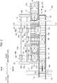
- a right and left direction and an up and down direction of the warehouse body 1 are defined as indicated by arrows in FIG. 1 .
- a front and rear direction of the warehouse body 1 is defined in addition to the right and left direction of the warehouse body 1, in accordance with FIG. 1 .
- the right and left direction, the upper and lower direction, and the front and rear direction of the warehouse body 1 are defined in accordance with FIGS. 1 and 2 .
- the right and left direction, the up and down direction, and the front and rear direction are perpendicular to one another.
- the warehouse body 1 includes a housing 17 formed in a rectangular shape.
- First to fourth entrances 17a-17d are formed on the right side of the housing 17.
- first to fourth exits 17e-17h are formed on the left side of the housing 17.
- the first to fourth entrances 17a-17d and the first to fourth exits 17e-17h are arranged in the height direction of the housing 17.
- the first entrance 17a corresponds to the first exit 17e.
- the second to fourth entrances 17b-17d correspond to the second to fourth exits 17f-17h, respectively.
- the first to fourth entrances 17a-17d each are an example of "the entrance” of the present invention.
- the first to fourth exits 17e-17h each are an example of "the exit" of the present invention.
- the housing 17 has therein first to fourth rack units 19a-19d.
- the first to fourth rack units 19a-19d are arranged in layers in the height direction of the housing 17. With this structure, in the housing 17, the first rack unit 19a is located on the top of the layers and the fourth rack unit 19d is located on the bottom of the layers. Also, in the housing 17, the first to fourth rack units 19a-19d are arranged horizontally in the right and left direction. It is to be noted that the number of the rack units provided in the housing 17 may be designed appropriately. It is also to be noted that the number of the entrances and the number of the exits formed in the housing 17 may be designed appropriately correspondingly to the number of the rack units.
- the first rack unit 19a is connected to the first entrance 17a and the first exit 17e.
- the second rack unit 19b is connected to the second entrance 17b and the second exit 17f.
- the third rack unit 19c is connected to the third entrance 17c and the third exit 17g.
- the fourth rack unit 19d is connected to the fourth entrance 17d and the fourth exit 17h.
- the first to fourth rack units 19a-19d have the same configuration that includes a storage rack 21 and a transfer rack 23. The following will describe configurations of the storage rack 21 and the transfer rack 23 based on the first rack unit 19a.
- the storage rack 21 extends horizontally in the right and left direction from the first entrance 17a side to the first exit 17e side.
- the storage rack 21 includes an introducing section 21a and a rack body 21b.
- the introducing section 21a is connected to the right end of the rack body 21b.
- the introducing section 21a extends from the rack body 21b toward the first entrance 17a side and faces the first elevator device 3 from the first entrance 17a illustrated in FIG. 1 .
- the introducing section 21a includes a first floor face 210 that is horizontal in the right and left direction and the front and rear direction and a first vertical wall 211.
- the first vertical wall 211 extends vertically upward relative to the first floor face 210 and is configured to prevent the items 9 moving along the introducing section 21a from being dropped therefrom.
- the rack body 21b is formed so that the rack body 21b and the introducing section 21a have the same width in the front and rear direction.
- the rack body 21b is connected to the introducing section 21a and extends to the left side.
- the rack body 21b is configured to store the items 9 that are transferred through the introducing section 21a.
- the rack body 21b includes a second floor face 212 that is horizontal in the right and left direction and the front and rear direction, and a second vertical wall 213.
- the second floor face 212 is an example of "the floor face" of the present invention.
- the second vertical wall 213 extends vertically upward relative to the second floor face 212 and is configured to prevent the items 9 and the selected items 90 from being dropped from the rack body 21b.
- a plurality of detection sensors 214 is provided to the second vertical wall 213.
- the detection sensors 214 are arranged in the right and left direction on the second vertical wall 213 at predetermined intervals between them.
- the number of the detection sensors 214 is equal to the number of the items 9 that can be stored on the rack body 21b.
- the detection sensors 214 each are an example of "the detection device" of the present invention.
- the detection sensors 214 are communicably connected to the work computer 7 illustrated in FIG. 1 .
- the detection sensors 214 detect positions of the items 9 on the rack body 21b as positional information and transmits the positional information to the work computer 7.
- a first belt conveyer device 25 is provided to the first floor face 210 of the introducing section 21a
- a roller conveyer device 27 is provided to the second floor face 212 of the rack body 21 b.
- the first belt conveyer device 25 and the roller conveyer device 27 form "the first moving unit" of the present invention.
- the first belt conveyer device 25 is a commercially available product.
- the first belt conveyer device 25 is controllable by the work computer 7 illustrated in FIG. 1 .
- the first belt conveyer device 25 transfers the items 9 placed thereon from the first entrance 17a to the rack body 21b on the introducing section 21a.
- the roller conveyer device 27 includes a plurality of transfer rollers 27a.
- Each of the transfer rollers 27a has a motor (not illustrated), and is configured to rotate in R1 direction indicated in the same figure about a rotational axis O1 extending in the axial direction.
- the transfer rollers 27a of the roller conveyer device 27 are individually controllable by the work computer 7 illustrated in FIG. 1 . It is to be noted that in FIG. 3 , the items 9 are drawn with imaginary lines for the ease of explanation.
- the roller conveyer device 27 is configured to transfer the items 9 that are transferred along the introducing section 21a to the left side on the rack body 21b, i.e., toward the first exit 17e side with the rotation of the transfer rollers 27a, as indicated by a white arrow in FIG. 2 .
- the roller conveyer device 27 is also configured to rest the items 9 on the rack body 21 b by stopping the rotation of the transfer rollers 27a via the work computer 7 for performing the storing operation of the items 9 on the rack body 21b, based on the positional information detected by the detection sensors 214. Accordingly, the roller conveyer device 27 functions also as "the resting device” of the present invention. In other words, the detection sensors 214, the work computer 7, and the roller conveyer device 27 form “the restriction unit” of the present invention. Details of the storage of the items 9 on the rack body 21b will be described later.
- the transfer rack 23 is disposed next to the storage rack 21 on the front side of the storage rack 21.
- the transfer rack 23 extends horizontally in the right and left direction from the first entrance 17a side toward the first exit 17e side and in parallel to the storage rack 21. Also, as illustrated in FIG. 4 , the transfer rack 23 is parallel to the rack body 21b in the right and left direction and the front and rear direction.
- the transfer rack 23 includes a third floor face 230 that is horizontal in the right and left direction and the front and rear direction, and a third vertical wall 231.
- the third vertical wall 231 extends vertically upward relative to the third floor face 230 and is configured to prevent the selected items 90 from being dropped from the transfer rack 23.
- the third floor face 230 is connected to the front end of the second floor face 212. In this way, the transfer rack 23 is connected to the front end of the rack body 21b.
- a second belt conveyer device 29 is provided to the third floor face 230 of the transfer rack 23.
- the second belt conveyer device 29 is an example of "the second moving unit" of the present invention.
- the second belt conveyer device 29 is a commercially available product.
- the second belt conveyer device 29 is controllable by the work computer 7 illustrated in FIG. 1 .
- the second belt conveyer device 29 transfers the selected items 90 placed thereon toward the first exit 17e side on the transfer rack 23.
- roller conveyer devices may be employed as alternatives to the first and second belt conveyer devices 25, 29.
- the warehouse body 1 includes first to fourth gate devices 31a-31d.
- the first gate device 31a is mounted to the first rack unit 19a and located near the first exit 17e in the housing 17.
- the second to fourth gate devices 31b-31d are mounted to the second to fourth rack units 19b-19d and located near the second to fourth exits 17f-17h, respectively, in the housing 17.
- the first to fourth gate devices 31a-31d have the same configuration that includes a device body 311 and a shield plate 312. Configurations of the device body 311 and the shield plate 312 will be described below based on the first gate device 31a.
- the device body 311 is mounted to the transfer rack 23 and located near the first exit 17e.
- the device body 311 has therein a drive unit (not illustrated) for oscillating the shield plate 312.
- the device body 311 is controllable by the work computer 7 illustrated in FIG. 1 .
- the shield plate 312 illustrated in FIG. 2 is oscillatably mounted to the device body 311
- the first gate device 31a is configured to switch between permission and prohibition of the carry-out of the selected items 90 that are transferred along the transfer rack 23 through the first exit 17e, by oscillating the shield plate 312 relative to the device body 311.
- the warehouse body 1 includes a pushing mechanism 33.
- the pushing mechanism 33 is an example of "the third moving unit" of the present invention.
- the pushing mechanism 33 is mounted in the housing 17 and disposed on the rear side of the first to fourth rack units 19a-19d.
- the pushing mechanism 33 comprises a first support post 35a, a second support post 35b, four guide rail groups 41, four pushing device groups 43, and the work computer 7. It is to be noted that the number of the guide rail groups 41 is determined correspondingly to the number of the rack units.
- the first and second support posts 35a, 35b are fixed to a floor section of the housing 17 and extend vertically upward. As illustrated in FIG. 2 , the first support post 35a and the second support post 35b are disposed so as to have an interval that is substantially equal to the length of the rack body 21 b of the storage rack 21 in the right and left direction, between the first support post 35a and the second support post 35b.
- each of the guide rail groups 41 is formed by first to fifth guide rails 37a-37e. As illustrated in FIG. 1 , each of the guide rail groups 41 is fixed to the first and second support posts 35a, 35b so as to extend between the first support post 35a and the second support post 35b. In this way, the guide rail groups 41 are located on the rear side of the first to fourth rack units 19a-19d.
- the guide rail groups 41 i.e., the first to fifth guide rails 37a-37e are made of metal. Therefore, the first to fifth guide rails 37a-37e have a rigidity that withstands the weight of first to fifth pushing devices 39a-39e, which will be described later, as well as the reaction force that occurs when rods 393 of the first to fifth pushing devices 39a-39e push the selected items 90.
- the first to fifth guide rails 37a-37e extend horizontally in the right and left direction along the storage rack 21.
- the first to third guide rails 37a-37c are arranged in the height direction at predetermined intervals between them.
- the fourth and fifth guide rails 37d, 37e are disposed on the rear side of the first to third guide rails 37a-37c at a predetermined distance from the first to third guide rails 37a-37c.
- the fourth guide rail 37d and the fifth guide rail 37e are also arranged in the height direction at a predetermined interval. More specifically, the fourth guide rail 37d is disposed between the first guide rail 37a and the second guide rail 37b, and the fifth guide rail 37e is disposed between the second guide rail 37b and the third guide rail 37c.
- each of the pushing device groups 43 is formed by the first to fifth pushing devices 39a-39e.
- the first to fifth pushing devices 39a-39e are controllable by the work computer 7 illustrated in FIG. 1 .
- the first to fifth pushing devices 39a-39e have the same configuration that includes a device body 391 and a rod 393. It is to be noted that the number of the pushing devices forming a pushing device group 43 may be designed appropriately. It is also to be noted that the number of the guide rails forming a guide rail group 41 is determined correspondingly to the number of the pushing devices.
- Each device body 391 has an insertion hole 391a.
- the insertion holes 391a are each formed through the device bodies 391 in the right and left direction so as to allow insertion of the first to fifth guide rails 37a-37e.
- each device body 391 has therein the guide roller 40a, first and second driven rollers 40b, 40c, and first and second actuator motors 40d, 40e.
- the guide roller 40a and the first and second driven rollers 40b, 40c are disposed so as to face each other.
- the first actuator motor 40d actuates the guide roller 40a.
- the second actuator motor 40e actuates the rod 393.
- the first and second actuator motors 40d, 40e are controllable by the work computer 7 illustrated in FIG. 1 .
- the first and second support posts 35a, 35b, the guide rail groups 41, the guide rollers 40a, the first and second driven rollers 40b, 40c, and the first actuator motor 40d form "the guide device" of the present invention. It is to be noted that the number of the guide rollers 40a and the first and second driven rollers 40b, 40c may be designed appropriately.
- the rods 393 are made of metal and have a rigidity that withstands the reaction force that occurs when the rods 393 push the selected items 90.
- Each rod 393 is disposed on the front face of the device body 391.
- Each rod 393 extends frontward from the device body 391 in an axial direction of the rod 393.
- each rod 393 has a first length L1 corresponding to the length when the rod 393 is most retracted, and a second length L2 corresponding to the length when the rod 393 is most extended.
- the rod 393 is extendable and retractable in stages between the first length L1 and the second length L2. It is to be noted that the size or the length of the rod 393 may be designed appropriately in accordance with factors, such as the size or the weight of the items 9 stored on the storage rack 21 or the size or weight of the selected items 90.
- the first guide rail 37a is inserted through the insertion hole 391a of the device body 391. Meanwhile, in the device body 391, the guide roller 40a and the first and second driven rollers 40b, 40c hold the first guide rail 37a. In this way, by mounting the device body 391 to the first guide rail 37a, the first pushing device 39a is mounted to the first guide rail 37a on the rear side of the storage rack 21.
- the first pushing device 39a is movable horizontally in the right and left direction relative to the storage rack 21 while being guided by the first guide rail 37a, in response to the first and second driven rollers 40b, 40c being driven by the guide roller 40a that is actuated by the first actuator motor 40d.
- the second to fifth pushing devices 39b-39e are mounted to the second to fifth guide rails 37b-37e, respectively, on the rear side of the storage rack 21.
- the second to fifth pushing devices 39b-39e are also movable horizontally in the right and left direction relative to the storage rack 21 while being guided by the second to fifth guide rails 37b-37e, respectively.
- the first to fifth pushing devices 39a-39e are movable independently from one another by the control of the work computer 7.
- the first to third pushing devices 39a-39c are arranged in the height direction of the items 9.
- the fourth and fifth pushing devices 39d, 39e are disposed on the rear side of the first to third pushing devices 39a-39c.
- the first to third pushing devices 39a-39c are arranged parallel to the fourth and fifth pushing devices 39d, 39e in the extending direction of the storage rack 21.
- the fourth and fifth pushing devices 39d, 39e are also arranged in the height direction of the items 9.
- the fourth pushing device 39d is located on the rear side of the first to third pushing devices 39a-39c and between the first pushing device 39a and the second pushing device 39b.
- the fifth pushing device 39e is also located on the rear side of the first to third pushing devices 39a-39c and between the second pushing device 39b and the third pushing device 39c.
- a clearance is provided between the first pushing device 39a and the second pushing device 39b in the height direction, and a clearance is provided between the second pushing device 39b and the second pushing device 39b in the height direction. Therefore, when the first to third pushing devices 39a-39c are movable relative to each other horizontally in the right and left direction while passing by each other in the height direction. Also, a clearance is provided between the fourth pushing device 39d and the fifth pushing device 39e in the height direction. Thus, the fourth and fifth pushing devices 39d, 39e are also movable relative to each other horizontally in the right and left direction while passing by each other in the height direction.
- a clearance is provided between the first to third pushing devices 39a-39c and the fourth and fifth pushing devices 39d, 39e in the front and rear direction. Therefore, the first to third pushing devices 39a-39c and the fourth and fifth pushing devices 39d, 39e are movable relative to each other horizontally in the right and left direction while passing by each other in the front and rear direction.
- the first elevator device 3 illustrated in FIG. 1 includes a plurality of mount bases 3a extending horizontally in the right and left direction, a plurality of guide rails 3b extending vertically in the up and down direction and perpendicularly to the mount bases 3a, and a device body 3c.
- a power device (not illustrated) for moving the mount bases 3a is mounted to the device body 3c.
- the first elevator device 3 is controllable by the work computer 7. With this configuration, in the first elevator device 3, the mount bases 3a are rotated around in the vertical direction along the guide rails 3b.
- the first elevator device 3 is configured such that the items 9 waiting at the waiting area 11 are placed one by one on each of the mount bases 3a and automatically transferred to the first to fourth entrances 17a-17d of the warehouse body 1.
- the second elevator device 5 having the same configuration as the first elevator device 3 includes a plurality of mount bases 5a, a plurality of guide rails 5b, and device body 5c.
- the second elevator device 5 is also controllable by the work computer 7. With this configuration, in the second elevator device 5, the mount bases 5a are rotated around in the vertical direction along the guide rails 5b.
- the mount bases 5a are rotated around in the vertical direction but opposite to the direction in which the mount bases 3a of the first elevator device 3 are rotated around.
- the second elevator device 5 is configured such that the selected items 90 that are carried out through the first to fourth exits 17e-17h are placed one by one on each of the mount bases 5a and automatically transferred to the receiving area 13.
- the work computer 7 includes a computer body 7a, a display 7b, and a keyboard 7c.
- the work computer 7 is disposed at a location away from the warehouse body 1.
- the computer body 7a has therein a ROM 70, a CPU 71, a storage medium 72, and the like.
- the ROM 70 stores therein programs for operating the warehouse system, such as a program for controlling the first and second belt conveyer devices 25, 29, the roller conveyer device 27, the first to fourth gate devices 31a-31d, the first to fifth pushing devices 39a-39e, and the first and second elevator devices 3, 5.
- the CPU 71 executes the programs and transmits control signals to each of the first and second belt conveyer devices 25, 29, the roller conveyer device 27, the first to fourth gate devices 31a-31d, the first to fifth pushing devices 39a-39e, and the first and second elevator devices 3, 5.
- the CPU 71 also transmits control signals to the roller conveyer device 27 based on the positional information detected by the detection sensors 214.
- the first and second belt conveyer devices 25, 29, the roller conveyer device 27, the first to fourth gate devices 31a-31d, the first to fifth pushing devices 39a-39e, and the first and second elevator devices 3, 5 are operable independently from each other.
- the storage medium 72 stores therein identification labels 9a attached to the items 9. Thus, the storage medium 72 stores the contents of the items 9 based on the identification labels 9a.
- the display 7b displays thereon information of the identification labels 9a, and information of the contents of the items 9 based on the identification labels 9a.
- the display 7b also displays thereon positional information of the items 9 on the rack bodies 21b of the storage racks 21 based on the positional information detected by the detection sensors 214.
- an operator (not illustrated) performs various pieces of control for operating the warehouse system.
- a plurality of the items 9 is carried in and stored on the warehouse body 1 and, of the stored items 9, the selected items 90 to be carried out are carried out from the warehouse body 1, which will be described below.
- the operator places the items 9 on the mount bases 3a at the waiting area 11.
- the items 9 placed on the mount bases 3a are moved upward by the first elevator device 3 and carried into the warehouse body 1 through one of the first to fourth entrances 17a-17d.
- through which of the first to fourth entrances 17a-17d the items 9 are carried into the warehouse body 1 is not critical.
- one of the first to fourth entrances 17a-17d that is available is selected in accordance with the storage condition in the first to fourth rack units 19a-19d of the storage rack 21.
- the item 9 that is carried in through the first entrance 17a is moved toward the first exit 17e side, i.e., toward the rack body 21b, on the introducing section 21a of the storage rack 21 by the first belt conveyer device 25.
- the item 9 moved to the rack body 21b is then moved toward the first exit 17e on the rack body 21b by the roller conveyer device 27.
- the item 9 that is carried in through the first entrance 17a is moved by the roller conveyer device 27 to the leftmost on the rack body 21b, that is, to a position closest to the first exit 17e.
- the detection sensor 214 that is located at the leftmost detects the position of the item 9, and transmits the positional information to the work computer 7.
- the work computer 7 stops the motion of the transfer rollers 27a of the roller conveyer device 27 on which the item 9 is placed. More specifically, the work computer 7 stops the motion of the transfer rollers 27a of a group G1 in FIG. 3 . In this way, the item 9 is stored on the rack body 21b.
- the work computer 7 keeps the transfer rollers 27a of the remaining groups other than the group G1 moving. Accordingly, the item 9 that is newly carried in through the first entrance 17a is moved toward the first exit 17e on the rack body 21b by the roller conveyer device 27.
- the work computer 7 controls the roller conveyer device 27 based on the positional information that is already received to thereby stop the moving of the item 9 carried in through the first entrance 17a while providing a specified distance from the item 9 already stored.
- the work computer 7 also causes the transfer rollers 27a of a group G2 to stop, following the transfer rollers 27a of the group G1 that are already stopped. Meanwhile, the work computer 7 keeps the transfer rollers 27a of the groups other than the groups G1 and G2 moving.
- the work computer 7 also causes the transfer rollers 27a of the groups G3 to G5 to stop sequentially to stop the moving of the items 9 along the rack body 21b. In this way, on the rack body 21b, the items 9 are sequentially stored at predetermined intervals between them in the right and left direction.
- the operator selects the item 9 to be carried out from among the items 9 stored on the warehouse body 1, based on the identification labels 9a and the information of the respective items 9 stored on the warehouse body 1 displayed on the display 7b illustrated in FIG. 1 .
- the item 9 thus selected turns into the selected item 90.
- the work computer 7 selects one from the first to fifth pushing devices 39a-39e to be operated, among the pushing device groups 43.
- the work computer 7 selects operative one from the first to fifth pushing devices 39a-39e of the pushing device group 43 that corresponds to the first rack unit 19.
- the work computer 7 selects operative one from the first to fifth pushing devices 39a-39e of the pushing device group 43 that corresponds to the one of the second to fourth rack units 19b-19d.
- the selection of the first to fifth pushing devices 39a-39e is performed based on the operating condition of the first to fifth pushing devices 39a-39e, the distance from the selected item 90, etc.
- the first pushing device 39a when the first pushing device 39a is selected, as illustrated in FIG. 2 , the first pushing device 39a is moved to the rear side of the selected item 90 while being guided by the first guide rail 37a. Then, the first pushing device 39a is actuated by the second actuator motor 40e, so that the rod 393 is extended from the first length L1 and brought into contact with the selected item 90. In this state, the second actuator motor 40e causes the rod 393 to extend to the second length L2 to thereby push the selected item 90 toward the transfer rack 23.
- the selected item 90 is transferred from the rack body 21b to the transfer rack 23 by the first pushing device 39a.
- the items 9 are stored at predetermined intervals between them in the right and left direction. Therefore, during the transfer of the selected item 90 from the rack body 21b to the transfer rack 23, the item 9 present next to the selected item 90 is prevented from being transferred to the transfer rack 23 together with the selected item 90.
- the second actuator motor 40e causes the rod 393 to retract to the first length L1. Also, in response to the transfer of the selected item 90 to the transfer rack 23, the work computer 7 resumes the motion of the transfer rollers 27a that have been stopped. Thus, the items 9 on the rack body 21b are moved so that the vacant space where the selected item 90 was present is filled.
- each pushing device group 43 is formed by the first to fifth pushing devices 39a-39e. Therefore, in each of the first to fourth rack units 19a-19d, it is possible to transfer up to five selected items 90 simultaneously to the transfer rack 23. In addition, in accordance with the size or the weight of the selected item 90, for example, it is possible to transfer the selected item 90 to the transfer rack 23 with the first, second, and fourth pushing devices 39a, 39b, 39d, or it is also possible to transfer the selected item 90 to the transfer rack 23 with the second, third, and fifth pushing devices 39b, 39c, 39e.
- the fourth pushing device 39d is located on the rear side of the first and second pushing devices 39a, 39b and between the first pushing device 39a and the second pushing device 39b.
- This configuration allows the fourth pushing device 39d to extend the rod 393 through the space between the first pushing device 39a and the second pushing device 39b to push the selected item 90.
- this configuration allows the fifth pushing device 39e to extend the rod 393 through the space between the second pushing device 39b and the third pushing device 39c to push the selected item 90.
- the first to third pushing devices 39a-39c do not hinder the fourth and fifth pushing devices 39d, 39e from pushing the selected item 90.
- the selected item 90 that is transferred to the transfer rack 23 is moved toward one of the first to fourth exits 17e-17h illustrated in FIG. 1 by the second belt conveyer device 29.
- the selected item 90 that is carried out through the one of the first to fourth exits 17e-17h is placed on the mount base 5a.
- the timing for placing the selected item 90 to be carried out through the one of the first to fourth exits 17e-17h on the mount base 5a is adjusted by the corresponding one of the first to fourth gate devices 31a-31d.
- the selected item 90 is descended by the second elevator device 5 and moved from the warehouse body 1 to the receiving area 13. In this way, the carrying-out operation of the selected item 90 is completed, and the operator can perform works such as further transportation of the selected item 90 to the destination.
- the first and second belt conveyor devices 25, 29, the roller conveyer device 27, and the first to fifth pushing devices 39a-39e are operated independently from each other while being controlled by the work computer 7. Therefore, it is possible to perform the moving of the items 9 by the first belt conveyer device 25 and the roller conveyer device 27 along the storage rack 21, the moving of the selected items 90 by the second belt conveyer device 29 along the transfer rack 23, and the transfer of the selected items 90 by the first to fifth pushing devices 39a-39e from the rack body 21b to the transfer rack 23 independently from each other.
- the storing operation of the items 9 that are carried in through the first to fourth entrances 17a-17d and the carrying-out operation of the selected items 90 may be performed simultaneously without using the plurality of the stacker cranes or the like.
- the first to fifth pushing devices 39a-39e forming the pushing device groups 43 are controlled by the work computer 7.
- the first to fifth guide rails 37a-37e forming the guide rail groups 41 guide the first to fifth pushing devices 39a-39e in the extending direction of the storage rack 21, so that the first to fifth pushing devices 39a-39e can move in the extending direction of the storage rack 21 to the position of the selected items 90. Therefore, the pushing mechanism 33 need not have the pushing devices of the number same as the number of the items 9 to be stored on the rack body 21b.
- the first warehouse system of the present invention it is possible to perform the storing operation of the items 9 and the carrying-out operation of the selected items 90 highly efficiently and to achieve cost reduction.
- the first to fifth pushing devices 39a-39e each include the device body 391 and the rod 393.
- the first to fifth pushing devices 39a-39e each extend the rod 393 to thereby push the selected item 90. Accordingly, in the warehouse system, the configuration of the first to fifth pushing devices 39a-39e can be simplified. In this regard also, the cost reduction is achieved.
- the rods 393 are made of metal and have a rigidity. Therefore, the rods 393 hardly bend by a reaction force that acts when the rods 393 push the selected items 90. Similarly, the guide rails 37a-37e hardly bend by the reaction force that occurs when the rods 393 push the selected items 90. For the reasons above, it is possible to push the selected items 90 in a suitable manner by the first to fifth pushing devices 39a-39e and to transfer the selected items 90 from the rack body 21b to the transfer rack 23 in a suitable manner.
- the first to third pushing devices 39a-39c are arranged in the height direction of the items 9, and the first to third pushing devices 39a-39c are arranged parallel to the fourth and fifth pushing devices 39d, 39e in the extending direction of the storage rack 21.
- the fourth and fifth pushing devices 39d, 39e are also arranged in the height direction of the items 9.
- a clearance is provided between each adjacent two of the first to fifth pushing devices 39a-39e.
- the work computer 7 causes the transfer rollers 27a of the roller conveyer device 27 to stop individually based on the positional information from the detection sensors 214. Accordingly, on the rack body 21b, it is possible to store the items 9 in a preferable manner at predetermined intervals between them in the right and left direction. Accordingly, in the warehouse system, it is possible to transfer the selected items 90 from the rack body 21 b to the transfer rack 23 accurately and also possible to surely prevent the items 9 that are not selected items 90 from being carried out through the first to fourth exits 17e-17h via the transfer rack 23.
- pushing device groups 43 are each formed by first to fifth pushing devices 45a-45e illustrated in FIGS. 5 and 6 .
- the first to fifth pushing devices 45a-45e each include a device body 451, a first chain 453, a second chain 455, and a guide gear 457.
- Each device body 451 has an insertion hole 451a.
- the insertion holes 451a are each formed through the device body 451 in the right and left direction so as to allow insertion of the first to fifth guide rails 37a-37e.
- the device body 451 has therein a guide roller 40a, first and second driven rollers 40b, 40c, and first and second actuator motors 40d, 40e.
- the second actuator motor 40e actuates the guide gear 457.
- first to third accommodation chambers 451b-451d are defined on the frontward side of the insertion hole 451a, and a guide passage 451e and an opening 451f are formed on the frontward side of the insertion hole 451a.
- the first accommodation chamber 451b is disposed on the front left side.
- a first guide groove 451g having a spiral shape is formed in the device body 451
- the second accommodation chamber 451c is disposed on the front right side.
- a second guide groove 451h having a spiral shape is formed in the device body 451, the third accommodation chamber 451d is disposed adjacently on the right side of the first accommodation chamber 451 b.
- the guide passage 451e is formed between the second accommodation chamber 451c and the third accommodation chamber 451d while extending in the front and rear direction.
- the opening 451f is formed in the front face of the device body 451 and in communication with the guide passage 451e.
- the first and second chains 453, 455 are made of metal and disposed in the device body 451. More specifically, the first chain 453 extends through the guide passage 451e and the first accommodation chamber 451b with a part of its front end protruded from the opening 451f to the outside of the device body 451. The first chain 453 is guided by the first guide groove 451g to be thereby accommodated spirally in the first accommodation chamber 451b.
- the second chain 455 extends through the guide passage 451e and the second accommodation chamber 451c with a part of its front end protruded from the opening 451f to the outside of the device body 451. The second chain 455 is guided by the second guide groove 451h to be thereby accommodated spirally in the second accommodation chamber 451c.
- the first and second chains 453,455 are adapted to be integrated by meshing with each other in the guide passage 451e.
- a pusher portion 459 is mounted to the front ends of the first and second chains 453, 455.
- the pusher portion 459 is configured to push the selected item 90 by being brought into contact with the selected item 90. It is to be noted that the size or the length of the first and second chains 453, 455 may be designed appropriately in accordance with factors such as the size or the weight of the selected items 90.
- the guide gear 457 is disposed in the third accommodation chamber 451d while protruding a part thereof into the guide passage 451e.
- the guide gear 457 is configured to rotate about a rotational axis O2 extending in the axial direction in R2 direction indicated in FIG. 5 or in R3 direction indicated in FIG. 6 by being actuated by the second actuator motor 40e.
- the guide gear 457 is in mesh with the first chain 453 in the guide passage 451e.
- the first to fifth pushing devices 45a-45e are mounted to the first to fifth guide rails 37a-37e, respectively. Accordingly, the first to third pushing devices 45a-45c are arranged in the height direction of the items 9. Also, the first to third pushing devices 45a-45c are arranged parallel to the fourth and fifth pushing devices 45d, 45e in the extending direction of the storage rack 21. In addition, the fourth and fifth pushing devices 45d, 45e are arranged in the height direction of the items 9. Because other configurations of the warehouse system are similar to those of the warehouse system according to the first embodiment, the same configurations are denoted by the same reference numerals and detailed description thereof will be omitted.
- the work computer 7 selects operative one from the first to fifth pushing devices 45a-45e, among the pushing device groups 43.
- the first pushing device 45a is selected, the first pushing device 45a is moved to the rear side of the selected item 90 while being guided by the first guide rail 37a.
- the second actuator motor 40e rotates the guide gear 457 in R3 direction indicated in FIG. 6 . Accordingly, the first and second chains 453, 455 are fed frontward from the device body 451 through the opening 451f while coming into mesh with each other in the guide passage 451 e.
- the first and second chains 453, 455 that are in a state in which large parts of the first and second chains 453, 455 are separated from each other as illustrated in FIG. 5 are fed frontward of the device body 451 through the opening 451f while increasing the integrated parts of the first and second chains 453, 455 by being meshed with each other as illustrated in FIG. 6 .
- the pusher portion 459 is brought into contact with the selected item 90.
- the first and second chains 453, 455 push the selected item 90 through the pusher portion 459.
- the second actuator motor 40e rotates the guide gear 457 in R2 direction indicated in FIG. 5 .
- the first and second chains 453, 455 are drawn into the device body 451.
- the first and second chains 453, 455 are disengaged from each other and accommodated in the first and second accommodation chambers 451b, 451c, respectively.
- pushing device groups 43 are each formed by first to fifth pushing devices 47a-47e illustrated in FIGS. 7 and 8 .
- the first to fifth pushing devices 47a-47e each include a device body 471, a pushing plate 473, and a link mechanism 475.
- Each device body 471 has an insertion hole 471a.
- the insertion holes 471a are each formed through the device body 471 in the right and left direction so as to allow insertion of the first to fifth guide rails 37a-37e.
- a first attachment portion 471b and a second attachment portion 471c are provided on a front face of the device body 471.
- the first attachment portion 471b and the second attachment portion 471c are each movable in the right and left direction on the front face of the device body 471.
- the device body 471 has therein a guide roller 40a, first and second driven rollers 40b, 40c, and first and second actuator motors 40d, 40e.
- the second actuator motor 40e actuates the first and second attachment portions 471 b, 471c.
- the pushing plate 473 is formed in a rectangular plate shape.
- the dimension of the pushing plate 473 in the right and left direction is greater than the dimension of the device body 471 in the right and left direction.
- the shape of the pushing plate 473 may be designed appropriately as long as the shape is greater than that of the front end of the rod 393 of the warehouse system according to the first embodiment or that of the pusher portion 459 of the warehouse system according to the second embodiment.
- a third attachment portion 473a and a fourth attachment portion 473b are provided on a rear face of the pushing plate 473.
- the third attachment portion 473a and the fourth attachment portion 473b are movable in the right and left direction on a rear face of the pushing plate 473 in accordance with the movement of the first and second attachment portions 471b, 471c.
- the link mechanism 475 comprises a plurality of link arms 475a and a plurality of connecting pins 475b.
- the link arms 475a are made of metal and connected to each other by the connecting pins 475b so as to be turnable relative to each other.
- the link arms 475a located at the rear end of the link mechanism 475 are connected to the first attachment portion 471 b and the second attachment portion 471c by the connecting pins 475b so as to be turnable.
- the link arms 475a located at the front end of the link mechanism 475 are connected to the third attachment portion 473a and the fourth attachment portion 473b by the connecting pins 475b so as to be turnable.
- the link mechanism 475 is configured to support the pushing plate 473 from behind while connecting the device body 471 and the pushing plate 473. It is to be noted that the number of the link arms 475a as well as the size or the length of the link arms 475a may be designed appropriately in accordance with factors such as the size or the weight of the selected items 90.
- the first attachment portion 471b and the second attachment portion 471c are movable in the right and left direction, so that the shape of the link mechanism 475 is changeable between a first state illustrated in FIG. 7 and a second state illustrated in FIG. 8 .
- the shape of the link mechanism 475 shifts from the first state to the second state while the first attachment portion 471b and the second attachment portion 471c are brought close to each other in the right and left direction
- the shape of the link mechanism 475 shifts from the second state to the first state while the first attachment portion 471b and the second attachment portion 471c are separated from each other in the right and left direction.
- the pushing plate 473 is brought closest to the device body 471.
- the pushing plate 473 is moved to the frontmost position from the device body 471.
- the first to fifth pushing devices 47a-47e are mounted to the first to fifth guide rails 37a-37e, respectively. Accordingly, the first to third pushing devices 47a-47c are arranged in the height direction of the items 9. Also, the first to third pushing devices 47a-47c are arranged parallel to the fourth and fifth pushing devices 47d, 47e in the extending direction of the storage rack 21. In addition, the fourth and fifth pushing devices 47d, 47e are arranged in the height direction of the items 9.
- Other configurations of the warehouse system are similar to those of the warehouse system according to the first embodiment.
- the work computer 7 selects operative one from the first to fifth pushing devices 47a-, among the pushing device groups 43.
- the first pushing device 47a is selected, the first pushing device 47a is moved to the rear side of the selected item 90 while being guided by the first guide rail 37a.
- the second actuator motor 40e moves the first and second attachment portions 471 b, 471c so that the first and second attachment portions 471 b, 471c are brought close to each other in the right and left direction. Accordingly, the link mechanism 475 moves the pushing plate 473 frontward while changing its shape from the first state to the second state.
- the pushing plate 473 is brought into contact with the selected item 90 to push the selected item 90.
- the link mechanism 475 supports the pushing plate 473 from behind.
- the second actuator motor 40e moves the first and second attachment portions 471b, 471c so that the first and second attachment portions 471b, 471c are separated away from each other in the right and left direction. Accordingly, the shape of the link mechanism 475 is shifted from the first state to the second state.
- the first to third pushing devices 47a-47c push the selected item 90 with the pushing plate 473.
- the dimension of the pushing plate 473 in the right and left direction is greater than the dimension of the device body 471 in the right and left direction, and the pushing plate 473 is supported by the link mechanism 475.
- the first to third pushing devices 47a-47c can transfer the selected item 90 from the rack body 21b to the transfer rack 23 in a stable manner.
- Other configurations of the warehouse system are similar to those of the warehouse system according to the first embodiment.
- a plurality of third belt conveyer devices 51 are provided on a second floor face 212 of a rack body 21b as alternatives to the roller conveyer device 27.
- the number of the third belt conveyor devices 51 is the same as the number of the items 9 that can be stored on the rack body 21b.
- the warehouse system includes no pushing mechanism 33.
- the first belt conveyer device 25 solely forms the "the first moving unit”.
- the third belt conveyer devices 51 are an example of "the conveyer device” of the present invention.
- the third belt conveyor devices 51 are controllable individually by the work computer 7 illustrated in FIG. 1 . That is, in the warehouse system, the third belt conveyor devices 51 and the work computer 7 form “the first moving unit” of the present invention.
- the third belt conveyor devices 51 function also as "the resting device” of the present invention.
- the third belt conveyer devices 51 are arranged in a line from the first entrance 17a side to the first exit 17e side at predetermined intervals therebetween.
- the distance between adjacent two of the third belt conveyor devices 51 is set to be smaller than a single item 9 or a single selected item 90. Therefore, the items 9 and the selected items 90 do not fall through the space between adjacent two of the third belt conveyor devices 51.
- Each of the third belt conveyer devices 51 includes a conveyer body 51a and a turning mechanism 51b.
- the turning mechanism 51b is disposed in the conveyer body 51a.
- the turning mechanism 51b is configured to turn the conveyer body 51a in R4 or R5 direction about a turning axis O3 extending in the up and down direction perpendicularly to the second floor face 212.
- the turning mechanism 51b turns the conveyer body 51a parallel to the second floor face 212. Accordingly, the conveyer body 51a being turned in R4 or R5 direction does not contact the second floor face 212.
- each of the third belt conveyer devices 51 when the conveyer body 51a is turned in R4 direction, the third belt conveyor device 51 is switched to a first moving state. Meanwhile, in each of the third belt conveyer devices 51, when the conveyer body 51a is turned in R5 direction, the third belt conveyor device 51 is switched to a second moving state.
- the third belt conveyer devices 51 are in the first moving state, the items 9 moved along the introducing section 21a are moved toward the first exit 17e along the rack body 21b.
- the third belt conveyor devices 51 are in the second moving state, the selected items 90 are transferred from the rack body 21b to the transfer rack, as illustrated in FIG. 10 . It is to be noted that FIG.
- FIG 9 illustrates a state in which the conveyer bodies 51a of all of the third belt conveyor devices 51 are turned in R4 direction, that is, all of the third belt conveyor devices 51 have been switched to the first moving state.
- Other configurations of the warehouse system are similar to those of the warehouse system according to the first embodiment.
- the work computer 7 causes the third belt conveyor devices 51 to stop individually based on the positional information from the detection sensors 214.
- the items 9 are sequentially stored at predetermined intervals between them in the right and left direction, as is the case of the warehouse system according to the first embodiment. Also, in the warehouse system, one item 9 is to be placed on each of the third belt conveyor devices 51.
- the operator operates the work computer 7 to turn only the conveyer body 51a of the third belt conveyor device 51 on which the selected item 90 is placed in R5 direction, and also to actuate the conveyer body 51a, as illustrated in FIG. 10 .
- the third belt conveyor device 51 on which the selected item 90 is placed is switched to the second moving state and transfers the selected item 90 from the rack body 21b to the transfer rack 23.
- the position of the selected item 90 is changed by being in contact with a third vertical wall 231, in addition to the second belt conveyer device 29 moving.
- the selected items 90 are carried out through the first to fourth exits 17e-17h and finally delivered to the receiving area 13, as is the case of the warehouse system according to the first embodiment.
- the work computer 7 causes the conveyer body 51a to turn in R4 direction.
- the first and second belt conveyor devices 25, 29 and the third belt conveyor devices 51 are operated independently from each other while being controlled by the work computer 7.
- the storing operation of the items 9 that are carried in through the first to fourth entrances 17a-17d and the carrying-out operation of the selected items 90 may be performed simultaneously.
- the pushing mechanism 33 is unnecessary. Therefore, in the warehouse system, it is possible to further reduce the cost. In addition, in the warehouse system, no space for disposing the pushing mechanism 33 is required in the warehouse body 1. Furthermore, since the third belt conveyor devices 51 are disposed in the rack body 21b, no space dedicated for the third belt conveyor devices 51 is necessary as well. Therefore, with this configuration, it is possible to reduce the size of the warehouse system.
- the third belt conveyor devices 51 of the same number as the number of the items 9 that can be stored on the rack body 21b are provided to the rack body 21b.
- Other effects of the warehouse system are similar to those of the warehouse system according to the first embodiment.
- a plurality of fourth belt conveyer devices 53 is provided on a second floor face 212 of a rack body 21b as alternatives to the third belt conveyor devices 51 according to the fourth embodiment.
- the number of the fourth belt conveyer devices 53 is the same as the number of the items 9 that can be stored on the rack body 21b.
- the warehouse system also includes no pushing mechanism 33.
- the first belt conveyer device 25 solely forms the "the first moving unit”.
- the fourth belt conveyer devices 53 are also an example of "the conveyer device” of the present invention.
- the fourth belt conveyer devices 53 are controllable individually by the work computer 7 illustrated in FIG. 1 . That is, in the warehouse system, the fourth belt conveyer devices 53 and the work computer 7 form “the third moving unit” of the present invention.
- the fourth belt conveyer devices 53 function also as "the resting device” of the present invention.
- the fourth belt conveyer devices 53 are provided on the second floor face 212 as is the case of the third belt conveyor devices 51.
- Each of the fourth belt conveyer devices 53 includes a conveyer body 53a and an actuator mechanism 53b.
- the conveyer bodies 53a are configured to transfer the items 9 that have been transferred through the introducing section 21a toward the first exit 17e along the rack body 21b.
- the actuator mechanism 53b is mounted on the conveyer body 53a and disposed between the conveyer body 53a and the second floor face 212.
- the position of the actuator mechanism 53b is changeable between a flat state in which the conveyer body 53a is parallel to the second floor face 212 as illustrated in FIG. 12 and a sloped state in which the conveyer body 53a is sloped relative to the second floor face 212 as illustrated in FIG. 13 .
- the actuator mechanism 53b is in the sloped state, the conveyer body 53a is sloped downward from the storage rack 21 side toward the transfer rack 23 side.
- the fourth belt conveyer device 53 when the actuator mechanism 53b enters the flat state, the fourth belt conveyer device 53 is switched the first moving state. Meanwhile, in each of the fourth belt conveyer devices 53, when the actuator mechanism 53b enters the sloped state, the fourth belt conveyer device 53 is switched to the second moving state.
- Other configurations of the warehouse system are similar to those of the warehouse system according to the first embodiment.
- the warehouse system when the storing operation of the items 9 is performed, for example, as illustrated in FIG. 11 , the items 9 that are carried in through the first entrance 17a are moved toward the rack body 21b along the introducing section 21a of the storage rack 21 by the first belt conveyer device 25.
- the state of the fourth belt conveyer devices 53 that are present in the first rack unit 19a is switched to the first moving state by the work computer 7.
- the items 9 that are delivered to the rack body 21b by the first belt conveyer device 25 are then moved toward the first exit 17e on the rack body 21b by the fourth belt conveyor devices 53.
- the work computer 7 causes the fourth belt conveyor devices 53 to stop individually based on the positional information from the detection sensors 214.
- the items 9 are sequentially stored at predetermined intervals between them in the right and left direction, as is the case of the warehouse system according to the first embodiment. Also, in the warehouse system, one item 9 is to be placed on each of the fourth belt conveyor devices 53, as is the case of the warehouse system according to the fourth embodiment.
- the operator operates the work computer 7 to change the position of only the fourth belt conveyer device 53 on which the selected item 90 is placed to the sloped state, as illustrated in FIG. 13 . Accordingly, the state of the fourth belt conveyor device 53 on which the selected item 90 is placed is switched to the second moving state. Accordingly, the selected item 90 is transferred from the rack body 21b to the transfer rack 23 while being slid down along the conveyer body 51a. In this way, the selected items 90 are carried out through the first to fourth exits 17e-17h and finally delivered to the receiving area 13, as is the case of the warehouse system according to the first embodiment.
- the work computer 7 changes the position of the actuator mechanism 53b to the flat state as illustrated in FIG. 12 , and switches the state of the fourth belt conveyer devices 53 to the first moving state.
- the first and second belt conveyor devices 25, 29 and the fourth belt conveyor devices 53 are operated independently from each other while being controlled by the work computer 7.
- the storing operation of the items 9 that are carried in through the first to fourth entrances 17a-17d and the carrying-out operation of the selected items 90 may be performed simultaneously.
- gravity may be utilized when transferring the selected items 90 from the rack body 21b to the transfer rack 23.
- no motive power for the conveyer body 53a is required when transferring the selected items 90 from the rack body 21b to the transfer rack 23.
- Other effects of the warehouse system are similar to those of the warehouse systems according to the first and fourth embodiments.
- a plurality of pushing mechanisms 61 is provided as alternatives to the pushing mechanisms 33 of the warehouse system according to the first embodiment.
- the pushing mechanisms 61 are also an example of "the third moving unit" of the present invention.
- the pushing mechanisms 61 are mounted in the housing 17 and disposed on the rear side of each of the first to fourth rack units 19a-19d. A plurality of the pushing mechanisms 61 is provided for each of the rear side of the first to fourth rack units 19a-19d. Also, the pushing mechanisms 61 are controllable by the work computer 7 illustrated in FIG. 1 . A configuration will be described hereafter based on the pushing mechanisms 61 disposed on the rear side of the first rack unit 19a.
- the pushing mechanisms 61 are arranged in a line in the extending direction of the storage rack 21, i.e., in the right and left direction.
- Each of the pushing mechanisms 61 includes first and second sprockets 63a, 63b, a roller chain 65, and a first pushing device 39a.
- the first pushing device 39a functions as "the pushing device" of the present invention.
- the first sprocket 63a and the second sprocket 63b are arranged in the right and left direction at a predetermined interval. More specifically, the first sprocket 63a and the second sprocket 63b are spaced apart in the right and left direction by a distance corresponding to three items 9. It is to be noted the distance between the first sprocket 63a and the second sprocket 63b in the right and left direction may be designed appropriately.
- a third actuator motor 67 is mounted to the first sprocket 63a.
- the third actuator motor 67 is controllable by the work computer 7.
- the third actuator motor 67 is configured to turn the first sprocket 63a around a rotational axis O4 that extends perpendicularly in the up and down direction. With this configuration, the first sprocket 63a is turnable in R6 or R7 direction around the rotational axis O4.
- the second sprocket 63b is rotatable around a rotational axis O5 that extends parallel to the rotational axis O4.
- the second sprocket 63b is turnable in R6 or R7 direction, following the first sprocket 63a. It is noted that the third actuator motor 67 is not mounted to the second sprocket 63b.
- the roller chain 65 is made of metal.
- the roller chain 65 is wrapped around the first sprocket 63a and the second sprocket 63b. With this configuration, by turning the first and second sprockets 63a, 63b in R6 direction, the roller chain 65 rotates in R6 direction between the first sprocket 63a and the second sprocket 63b. On the other hand, by turning the first and second sprockets 63a, 63b in R7 direction, the roller chain 65 rotates in R7 direction between the first sprocket 63a and the second sprocket 63b.
- the first and second sprockets 63a, 63b, the third actuator motor 67, and the roller chain 65 form "the guide device" of the present invention.
- the first pushing device 39a is fixed to the roller chain 65. Also, in the warehouse system, the device body 391 of the first pushing device 39a does not have the guide roller 40a, the first and second driven rollers 40b, 40c, and the first actuator motor 40d.
- the first pushing device 39a moves between the first sprocket 63a and the second sprocket 63b horizontally in the right and left direction relative to the storage rack 21. More specifically, when the roller chain 65 rotates in R6 direction, the first pushing device 39a moves horizontally to the right relative to the storage rack 21. Meanwhile, when the roller chain 65 rotates in R7 direction, the first pushing device 39a moves horizontally to the left relative to the storage rack 21.
- the first sprocket 63a and the second sprocket 63b are spaced apart in the right and left direction by a distance corresponding to three items 9, so that the first pushing device 39a is movable between the first sprocket 63a and the second sprocket 63b in the right and left direction by the distance corresponding to three items 9.
- Other configurations of the warehouse system are similar to those of the warehouse system according to the first embodiment.
- the items 9 are sequentially stored at predetermined intervals between them in the right and left direction, as is the case of the warehouse system according to the first embodiment.
- the intervals between the items 9 stored on the rack body 21b in the right and left direction is adjusted according to the movable range of the first pushing device 39a of each of the pushing mechanisms 61 in the right and left direction.
- the work computer 7 selects the pushing mechanism 61 at the position corresponding to the selected item 90 on the rack body 21b. Then, the work computer 7 actuates the third actuator motor 67 of the selected pushing mechanism 61 to turn the first sprocket 63a in R6 or R7 direction to thereby move the first pushing device 39a to the rear side of the selected item 90. Then, the first pushing device 39a extends a rod 393 as is the case of the warehouse system according to the first embodiment. Thus, the rod 393 pushes the selected item 90 to transfer the selected item 90 from the rack body 21b to the transfer rack 23. In the warehouse system, the selected items 90 are also carried out through the first to fourth exits 17e-17h and finally delivered to the receiving area 13.
- the first and second belt conveyer devices 25, 29, the roller conveyer device 27, and the pushing mechanisms 61 are operated independently from each other while being controlled by the work computer 7.
- the storing operation of the items 9 that are carried in through the first to fourth entrances 17a-17d and the carrying-out operation of the selected items 90 may be performed simultaneously.
- the configuration of the pushing mechanisms 61 is simplified as compared with the warehouse system according to the first embodiment and thus, it is possible to reduce the cost.
- Other effects of the warehouse system are similar to those of the warehouse system according to the first embodiment.
- a conveyer device dedicated to transfer which is configured to transfer the item 9 or the selected item 90 only in the right and left direction along the rack body 21b, may be provided on the second floor face 212.
- the conveyer device dedicated to transfer transfers the selected item 90 to the third belt conveyor device 51.
- each item 9 may be stored on the rack body 21b in a state in which the item 9 is placed on a cart or the like having casters so that the selected item 90 can be transferred from the rack body 21b to the transfer rack 23 in a suitable manner by the fourth belt conveyer device 53.
- a plurality of pushing mechanisms 61 may be arranged in the height direction.
- the pushing mechanisms 61 may be arranged in parallel in the extending direction of the storage rack 21.
- the pushing mechanisms 61 are arranged in a line in the extending direction of the storage rack 21.
- the configuration is not limited thereto.
- One pushing mechanism 61 may be provided to each of the first to fourth rack units 19a-19d by arranging the first sprocket 63a and the second sprocket 63b spaced apart by a distance substantially equal to the length of the rack body 21b in the right and left direction.
- each pushing mechanism 61 may include the first pushing device 45a of the warehouse system according to the second embodiment, or the first pushing device 47a of the warehouse system according to the third embodiment, as an alternative to the first pushing device 39a.
- each roller conveyer device 27 In the warehouse system according to the first embodiment, in each roller conveyer device 27, all of the transfer rollers 27a are rotated individually by the motor. However, the roller conveyer device 27 is not limited thereto.
- the roller conveyer device 27 include transfer rollers 27a that are rotated by a motor and driven rollers that are rotated following the transfer rollers 27a. In this case, each group of the roller conveyer device 27 illustrated in FIG. 3 is formed by the transfer rollers 27a and the driven rollers.
- the third belt conveyor devices 51 may be provided also to the introducing section 21a instead of the first belt conveyer device 25.
- the third belt conveyor devices 51 provided to the introducing section 21a function as "the first moving unit" of the present invention.
- the fourth belt conveyor devices 53 may be provided also to the introducing section 21a instead of the first belt conveyer device 25.
- the fourth belt conveyor devices 53 provided to the introducing section 21a function as "the first moving unit" of the present invention.
- the present invention is applicable to a logistics system.
Landscapes
- Engineering & Computer Science (AREA)
- Mechanical Engineering (AREA)
- Warehouses Or Storage Devices (AREA)
Abstract
Description
- The present invention relates to a warehouse system.
- Conventionally, various warehouse systems have been proposed for carrying in and storing a plurality of articles and carrying out selected articles that are to be carried out, from among the stored articles. For example, a warehouse system disclosed in Patent Document 1 includes a pair of storage racks disposed horizontally and facing each other, and a stacker crane. Each of the storage racks is formed by a plurality of support posts, a plurality of horizontal side members, and a plurality of braces. These support posts, horizontal side members, and braces form a plurality of storage portions in each of the storage racks. The storage portions are arranged in a grid, and each of the storage portions is configured to store therein an article.
- The stacker crane is disposed between the storage racks that face each other. The stacker crane has a travel cart configured to travel along a width direction of the storage racks, a lift platform that is movable in a height direction of the storage racks with an article placed thereon, and slide forks that are attached to the lift platform so that the slide forks can extend from and retract into the lift platform.
- In the warehouse system, when carrying an article into the storage racks, a worker places an article to be carried in on the lift platform. Then, the worker operates the stacker crane to move the lift platform to a position of a storage portion in which no article is stored. After that, the worker causes the slide forks to extend so that the article placed on the lift platform is stored in the storage portion. When carrying out a selected article, on the other hand, the worker operates the stacker crane to move the lift platform to a position of a storage portion in which the selected article is stored. After that, the worker causes the slide forks to extend to place the selected article stored on the storage portion on the lift platform. In this way, the selected article is transferred by the stacker crane.
- Patent Document 1:
Japanese Patent Application Publication No. 2013-103822 - However, in the conventional warehouse system described above, in order to store an article in a storage portion and to take out a selected article from a storage portion, the stacker crane is moved to the position of the target storage portion. Therefore, in the warehouse system, it is not possible to perform a carrying-out operation of a selected article while a storing operation of articles is performed using the stacker crane, so that the efficiency of the storing operation and the carrying-out operation is low.
- In view of this, it may be conceived to use a plurality of stacker cranes so that the storing operation of articles and the carrying-out operation of selected articles are performed separately using the stacker cranes separately. In this case, however, costs for the warehouse system rises.
- The present invention has been made in view of the conventional situation above, and it is an object to be solved by the invention to provide a warehouse system in which a storing operation of articles and a carrying-out operation of selected articles can be performed highly efficiently and that can achieve cost reduction.
- A first warehouse system of the present invention is a warehouse system in which a plurality of articles is carried in and stored, and from which selected articles that are to be carried out are carried out, the selected articles being the articles that are selected from among the stored articles, the first warehouse system including:
- an entrance through which the articles are carried in;
- an exit through which the selected articles are carried out;
- a storage rack that extends from an entrance side toward an exit side and on which the articles are stored;
- a transfer rack that is disposed next to the storage rack, extends from the entrance side toward the exit side in parallel to the storage rack, and on which the selected articles are to be placed;
- a selection unit that is configured to select the selected articles from among the articles stored on the storage rack;
- a first moving unit that is configured to move the articles in an extending direction of the storage rack on the storage rack;
- a second moving unit that is configured to be operated independently from the first moving unit and to move the selected articles toward the exit side on the transfer rack; and
- a third moving unit that is configured to be operated independently from the first moving unit and the second moving unit and to transfer the selected articles from the storage rack to the transfer rack.
- The first warehouse system is characterized in that the third moving unit includes a pushing device configured to push the selected articles toward the transfer rack;
- a guide device configured to guide the pushing device in the extending direction of the storage rack; and
- a control device configured to control the pushing device and the guide device.
- In the first warehouse system of the present invention, the articles that are carried in through the entrance are sequentially stored on the storage rack by moving the articles toward the exit side on the storage rack by the first moving unit. Then, the selection unit selects the selected articles from among the articles stored on the storage rack. With this, the third moving unit transfers the selected articles from the storage rack to the transfer rack. Then, the selected articles are moved toward the exit side on the transfer rack by the second moving unit. In this way, the selected articles are sequentially carried out through the exit.
- In the warehouse system, the first moving unit, the second moving unit, and the third moving unit are operated independently from one another. Therefore, the moving of the articles on the storage rack by the first moving unit, the moving of the selected articles on the transfer rack by the second moving unit, and the transfer of the selected articles from the storage rack to the transfer rack by the third moving unit may be performed independently from one another. With the configuration of the warehouse system, the storing operation of the articles that are carried in through the entrance and the carrying-out operation of the selected articles may be performed simultaneously without using a plurality of stacker cranes or similar devices.
- Therefore, according to the first warehouse system of the present invention, it is possible to perform the storing operation of articles and the carrying-out operation of selected articles highly efficiently and to achieve cost reduction.
- In particular, in the warehouse system, the third moving unit includes the pushing device and the guide device, and the control device. Furthermore, the guide device guides the pushing device in the extending direction of the storage rack, so that the pushing device is moved in the extending direction of the storage rack to the position of the selected article. Therefore, the third moving unit need not have the pushing devices of the same number as the number of articles to be stored on the storage rack. In this regard also, it is possible to achieve cost reduction with the warehouse system.
- The pushing device may include a device body mounted to the guide device, and a rod that is disposed in the device body, extendable in an axial direction, and configured to push the selected articles. The rod is extendable and retractable between a first length and a second length that is greater than the first length. The rod preferably pushes a selected article while extending to the second length. In this case, the configuration of the pushing device is simplified, so that the cost for the pushing device may be reduced.
- The pushing device may also include a device body mounted to the guide device, and a first chain and a second chain that are disposed in the device body. It is also preferable that the first chain and the second chain extend toward a selected article while coming into mesh each other from a state in which the first chain and the second chain are at least partially separated from each other to push the selected articles. In this case, it is possible to reduce the size of the pushing device as compared with the configuration of a pushing device that pushes a selected article by bringing the rod into contact with the selected article.
- Furthermore, the pushing device may include a device body that is mounted to the guide device, a pushing plate having a plate shape, and a link mechanism that connects the device body and the pushing plate and supports the pushing plate. In addition, a shape of the link mechanism may be changeable between a first state and a second state in which the link mechanism extends further than the first state toward the selected articles. It is also preferable that the pushing plate pushes the selected article by changing the shape of the link mechanism from the first state to the second state. In this case, the pushing device can transfer the selected article from the storage rack to the transfer rack stably by pushing the selected article with the pushing plate.
- It is preferable that the warehouse system includes a plurality of the pushing devices. In this case, a plurality of selected articles may be transferred simultaneously from the storage rack to the transfer rack with the third moving unit. Therefore, in the warehouse system, it is possible to more efficiently perform the carrying-out operation of the selected articles. It is noted that, in this case, the number of the plurality of the pushing devices is not necessarily the same as the number of the articles to be stored on the storage rack.
- It is preferable that the pushing devices are arranged in a height direction of the articles in such a manner that the pushing devices are movable relative to each other. It is also preferable that the pushing devices are arranged in parallel in the extending direction of the storage rack in such a manner that the pushing devices are movable relative to each other.
- In these cases, the pushing devices are prevented from interfering with each other while moving in the extending direction of the storage rack. Therefore, the pushing devices can move smoothly to the position of the selected articles.
- A second warehouse system of the present invention is a warehouse system in which a plurality of articles is carried in and stored, and from which selected articles that are to be carried out are carried out, the selected articles being the articles that are selected from among the stored articles, the second warehouse system including:
- an entrance through which the articles are carried in;
- an exit through which the selected articles are carried out;
- a storage rack that extends from an entrance side toward an exit side and is configured to store the articles;
- a transfer rack that is disposed next to the storage rack, extends from the entrance side toward the exit side in parallel to the storage rack, and on which the selected articles are to be placed;
- a selection unit configured to select the selected articles from among the articles stored on the storage rack;
- a first moving unit configured to move the articles in an extending direction of the storage rack on the storage rack;
- a second moving unit that is configured to be operated independently from the first moving unit and to move the selected articles toward the exit side on the transfer rack; and
- a third moving unit that is operated independently from the first moving unit and the second moving unit, and is switchable between a first moving state in which the third moving unit moves the articles in the extending direction of the storage rack and a second moving state in which the third moving unit transfers the selected articles from the storage rack to the transfer rack.
- The second warehouse system is characterized in that the third moving unit includes a plurality of conveyer devices that are provided to the storage rack and that are each switchable between the first moving state and the second moving state, and
a control device configured to switch the conveyer devices individually between the first moving state and the second moving state. - Also in the second warehouse system of the present invention, the first moving unit, the second moving unit, and the third moving unit are operated independently from one another. Therefore, with the configurations of these warehouse systems, the storing operation of the articles that are carried in through the entrance and the carrying-out operation of the selected articles may be performed simultaneously without using a plurality of stacker cranes or similar devices.
- Therefore, according to the second warehouse system of the present invention, it is possible to perform the storing operation of articles and the carrying-out operation of selected articles highly efficiently and to achieve cost reduction.
- In particular, in the second warehouse system, the conveyer devices of the third moving unit are disposed in the storage rack. With this configuration, it is possible to reduce the size of the warehouse system.
- The storage rack has a floor face on which the conveyer devices are disposed. It is preferable that each of the conveyer devices turns about a rotational axis extending perpendicular to the floor face to switch its state between the first moving state and the second moving state. In this case, the switching between the first moving state and the second moving state may be performed in a suitable manner.
- Furthermore, it is preferable that in the second moving state, the conveyer devices are sloped downward from a storage rack side to a transfer rack side. In this case, a gravity is utilized when transferring the selected articles from the storage rack to the transfer rack, so that the force for transferring the selected articles from the storage rack to the transfer rack can be reduced, and the need for a force for transferring the selected articles from the storage rack to the transfer rack is eliminated.
- The first warehouse system and the second warehouse system of the present invention preferably further include a restriction unit configured to restrict the articles on the storage rack from being transferred to the transfer rack together with the selected articles. In this case, it is possible to transfer the selected articles from the storage rack to the transfer rack accurately, and to surely prevent articles that are not selected items from being carried out from the storage rack through the exit.
- It is preferable that the restriction unit includes a detection device that detects a position of an article on the storage rack as positional information, and a resting device configured to rest the articles on the storage rack while providing a specified distance between the articles in the extending direction of the storage rack based on the positional information. In this case, the articles on the storage rack are restricted from being transferred to the transfer rack together with the selected articles more suitably.
- According to the first warehouse system and the second warehouse system of the present invention, it is possible to perform the storing operation of articles and the carrying-out operation of selected articles highly efficiently and to achieve cost reduction.
-
- [
FIG. 1] FIG. 1 is a schematic view of a warehouse system according to a first embodiment. - [
FIG. 2] FIG. 2 is a top view illustrating a storage rack, a transfer rack, first to third moving units, and others of the warehouse system according to the first embodiment. - [
FIG. 3] FIG. 3 is a front view of the warehouse system according to the first embodiment as viewed in a D1 direction ofFIG. 2 , illustrating the storage rack and others. - [
FIG. 4] FIG. 4 is a cross-sectional view of the warehouse system according to the first embodiment taken along line A-A ofFIG. 2 . - [
FIG. 5] FIG. 5 is a fragmentary cross-sectional view of a warehouse system according to a second embodiment, illustrating a pushing device. - [
FIG. 6] FIG. 6 is a fragmentary cross-sectional view of the warehouse system according to the second embodiment, illustrating the pushing device. - [
FIG. 7] FIG. 7 is a top view of a warehouse system according to a third embodiment, illustrating a pushing device. - [
FIG. 8] FIG. 8 is a top view of the warehouse system according to the third embodiment, illustrating a pushing device. - [
FIG. 9] FIG. 9 is a top view illustrating a storage rack, a transfer rack, first to third moving units, and others of a warehouse system according to a fourth embodiment. - [
FIG. 10] FIG. 10 is a top view of the warehouse system according to the fourth embodiment, illustrating a state in which a selected article is transferred from the storage rack to the transfer rack. - [
FIG. 11] FIG. 11 is a top view illustrating a storage rack, a transfer rack, first to third moving units, and others of a warehouse system according to a fifth embodiment. - [
FIG. 12] FIG. 12 is a cross-sectional view of the warehouse system according to the fifth embodiment taken along line B-B ofFIG. 11 . - [
FIG. 13] FIG. 13 is a cross-sectional view similar toFIG. 12 of the warehouse system according to the fifth embodiment, illustrating a state in which a selected article is transferred from the storage rack to the transfer rack. - [
FIG. 14] FIG. 14 is a top view illustrating a storage rack, a transfer rack, first to third moving units, and others of a warehouse system according to a sixth embodiment. - The following will describe first to sixth embodiments of the present invention with reference to drawings.
- As illustrated in
FIG. 1 , a warehouse system according to a first embodiment includes a warehouse body 1, afirst elevator device 3, asecond elevator device 5, and awork computer 7. The warehouse system also includes a waitingarea 11 whereitems 9 that are to be carried into the warehouse body 1 await, and a receivingarea 13 where selecteditems 90 that are carried out from the warehouse body 1 are received. Theitems 9 is an example of "the articles" of the present invention, and the selecteditems 90 is an example of "the selected articles" of the present invention. Also, thework computer 7 is an example of "the selection unit" and "the control device" of the present invention. - As illustrated in
FIG. 2 , anidentification label 9a is attached on each of theitems 9. The identification labels 9a are created using numerals, letters, and diagrams, and the like. The identification labels 9a are created so as to have different contents among theitems 9 on which the identification labels 9a are attached. It is to be noted that the position at which the identification labels 9a are attached may be modified appropriately. - In the present embodiment, a right and left direction and an up and down direction of the warehouse body 1 are defined as indicated by arrows in
FIG. 1 . Also, inFIG. 2 , a front and rear direction of the warehouse body 1 is defined in addition to the right and left direction of the warehouse body 1, in accordance withFIG. 1 . InFIG. 3 and the subsequent figures, the right and left direction, the upper and lower direction, and the front and rear direction of the warehouse body 1 are defined in accordance withFIGS. 1 and2 . The right and left direction, the up and down direction, and the front and rear direction are perpendicular to one another. - As illustrated in
FIG. 1 , the warehouse body 1 includes ahousing 17 formed in a rectangular shape. First tofourth entrances 17a-17d are formed on the right side of thehousing 17. In addition, first tofourth exits 17e-17h are formed on the left side of thehousing 17. The first tofourth entrances 17a-17d and the first tofourth exits 17e-17h are arranged in the height direction of thehousing 17. Thefirst entrance 17a corresponds to thefirst exit 17e. Similarly, the second tofourth entrances 17b-17d correspond to the second tofourth exits 17f-17h, respectively. The first tofourth entrances 17a-17d each are an example of "the entrance" of the present invention. The first tofourth exits 17e-17h each are an example of "the exit" of the present invention. - The
housing 17 has therein first tofourth rack units 19a-19d. The first tofourth rack units 19a-19d are arranged in layers in the height direction of thehousing 17. With this structure, in thehousing 17, thefirst rack unit 19a is located on the top of the layers and thefourth rack unit 19d is located on the bottom of the layers. Also, in thehousing 17, the first tofourth rack units 19a-19d are arranged horizontally in the right and left direction. It is to be noted that the number of the rack units provided in thehousing 17 may be designed appropriately. It is also to be noted that the number of the entrances and the number of the exits formed in thehousing 17 may be designed appropriately correspondingly to the number of the rack units. - The
first rack unit 19a is connected to thefirst entrance 17a and thefirst exit 17e. Thesecond rack unit 19b is connected to thesecond entrance 17b and thesecond exit 17f. Thethird rack unit 19c is connected to thethird entrance 17c and thethird exit 17g. Thefourth rack unit 19d is connected to thefourth entrance 17d and thefourth exit 17h. - The first to
fourth rack units 19a-19d have the same configuration that includes astorage rack 21 and atransfer rack 23. The following will describe configurations of thestorage rack 21 and thetransfer rack 23 based on thefirst rack unit 19a. - As illustrated in
FIG. 2 , thestorage rack 21 extends horizontally in the right and left direction from thefirst entrance 17a side to thefirst exit 17e side. Thestorage rack 21 includes an introducingsection 21a and arack body 21b. The introducingsection 21a is connected to the right end of therack body 21b. The introducingsection 21a extends from therack body 21b toward thefirst entrance 17a side and faces thefirst elevator device 3 from thefirst entrance 17a illustrated inFIG. 1 . As illustrated inFIG. 2 , the introducingsection 21a includes afirst floor face 210 that is horizontal in the right and left direction and the front and rear direction and a firstvertical wall 211. The firstvertical wall 211 extends vertically upward relative to thefirst floor face 210 and is configured to prevent theitems 9 moving along the introducingsection 21a from being dropped therefrom. - The
rack body 21b is formed so that therack body 21b and the introducingsection 21a have the same width in the front and rear direction. Therack body 21b is connected to the introducingsection 21a and extends to the left side. Therack body 21b is configured to store theitems 9 that are transferred through the introducingsection 21a. Therack body 21b includes asecond floor face 212 that is horizontal in the right and left direction and the front and rear direction, and a secondvertical wall 213. Thesecond floor face 212 is an example of "the floor face" of the present invention. The secondvertical wall 213 extends vertically upward relative to thesecond floor face 212 and is configured to prevent theitems 9 and the selecteditems 90 from being dropped from therack body 21b. - As illustrated in
FIG. 3 , a plurality ofdetection sensors 214 is provided to the secondvertical wall 213. Thedetection sensors 214 are arranged in the right and left direction on the secondvertical wall 213 at predetermined intervals between them. In the present embodiment, the number of thedetection sensors 214 is equal to the number of theitems 9 that can be stored on therack body 21b. Thedetection sensors 214 each are an example of "the detection device" of the present invention. Thedetection sensors 214 are communicably connected to thework computer 7 illustrated inFIG. 1 . Thedetection sensors 214 detect positions of theitems 9 on therack body 21b as positional information and transmits the positional information to thework computer 7. - Also, a first
belt conveyer device 25 is provided to thefirst floor face 210 of the introducingsection 21a, aroller conveyer device 27 is provided to thesecond floor face 212 of therack body 21 b. The firstbelt conveyer device 25 and theroller conveyer device 27 form "the first moving unit" of the present invention. - The first
belt conveyer device 25 is a commercially available product. The firstbelt conveyer device 25 is controllable by thework computer 7 illustrated inFIG. 1 . As illustrated inFIG. 2 , the firstbelt conveyer device 25 transfers theitems 9 placed thereon from thefirst entrance 17a to therack body 21b on the introducingsection 21a. - As illustrated in
FIG. 3 , theroller conveyer device 27 includes a plurality oftransfer rollers 27a. Each of thetransfer rollers 27a has a motor (not illustrated), and is configured to rotate in R1 direction indicated in the same figure about a rotational axis O1 extending in the axial direction. Thetransfer rollers 27a of theroller conveyer device 27 are individually controllable by thework computer 7 illustrated inFIG. 1 . It is to be noted that inFIG. 3 , theitems 9 are drawn with imaginary lines for the ease of explanation. - The
roller conveyer device 27 is configured to transfer theitems 9 that are transferred along the introducingsection 21a to the left side on therack body 21b, i.e., toward thefirst exit 17e side with the rotation of thetransfer rollers 27a, as indicated by a white arrow inFIG. 2 . Theroller conveyer device 27 is also configured to rest theitems 9 on therack body 21 b by stopping the rotation of thetransfer rollers 27a via thework computer 7 for performing the storing operation of theitems 9 on therack body 21b, based on the positional information detected by thedetection sensors 214. Accordingly, theroller conveyer device 27 functions also as "the resting device" of the present invention. In other words, thedetection sensors 214, thework computer 7, and theroller conveyer device 27 form "the restriction unit" of the present invention. Details of the storage of theitems 9 on therack body 21b will be described later. - The
transfer rack 23 is disposed next to thestorage rack 21 on the front side of thestorage rack 21. Thetransfer rack 23 extends horizontally in the right and left direction from thefirst entrance 17a side toward thefirst exit 17e side and in parallel to thestorage rack 21. Also, as illustrated inFIG. 4 , thetransfer rack 23 is parallel to therack body 21b in the right and left direction and the front and rear direction. Thetransfer rack 23 includes athird floor face 230 that is horizontal in the right and left direction and the front and rear direction, and a thirdvertical wall 231. The thirdvertical wall 231 extends vertically upward relative to thethird floor face 230 and is configured to prevent the selecteditems 90 from being dropped from thetransfer rack 23. Thethird floor face 230 is connected to the front end of thesecond floor face 212. In this way, thetransfer rack 23 is connected to the front end of therack body 21b. - A second
belt conveyer device 29 is provided to thethird floor face 230 of thetransfer rack 23. The secondbelt conveyer device 29 is an example of "the second moving unit" of the present invention. As is the firstbelt conveyer device 25 described above, the secondbelt conveyer device 29 is a commercially available product. The secondbelt conveyer device 29 is controllable by thework computer 7 illustrated inFIG. 1 . As indicated by a black arrow inFIG. 2 , the secondbelt conveyer device 29 transfers the selecteditems 90 placed thereon toward thefirst exit 17e side on thetransfer rack 23. It is to be noted that roller conveyer devices may be employed as alternatives to the first and secondbelt conveyer devices - Also, as illustrated in
FIG. 1 , the warehouse body 1 includes first tofourth gate devices 31a-31d. Thefirst gate device 31a is mounted to thefirst rack unit 19a and located near thefirst exit 17e in thehousing 17. Similarly, the second tofourth gate devices 31b-31d are mounted to the second tofourth rack units 19b-19d and located near the second tofourth exits 17f-17h, respectively, in thehousing 17. - The first to
fourth gate devices 31a-31d have the same configuration that includes adevice body 311 and ashield plate 312. Configurations of thedevice body 311 and theshield plate 312 will be described below based on thefirst gate device 31a. - As illustrated in
FIG. 2 , thedevice body 311 is mounted to thetransfer rack 23 and located near thefirst exit 17e. Thedevice body 311 has therein a drive unit (not illustrated) for oscillating theshield plate 312. Thedevice body 311 is controllable by thework computer 7 illustrated inFIG. 1 . Theshield plate 312 illustrated inFIG. 2 is oscillatably mounted to thedevice body 311 Thefirst gate device 31a is configured to switch between permission and prohibition of the carry-out of the selecteditems 90 that are transferred along thetransfer rack 23 through thefirst exit 17e, by oscillating theshield plate 312 relative to thedevice body 311. - Also, as illustrated in
FIG. 1 , the warehouse body 1 includes a pushingmechanism 33. The pushingmechanism 33 is an example of "the third moving unit" of the present invention. The pushingmechanism 33 is mounted in thehousing 17 and disposed on the rear side of the first tofourth rack units 19a-19d. - The pushing
mechanism 33 comprises afirst support post 35a, asecond support post 35b, fourguide rail groups 41, four pushingdevice groups 43, and thework computer 7. It is to be noted that the number of theguide rail groups 41 is determined correspondingly to the number of the rack units. - The first and
second support posts housing 17 and extend vertically upward. As illustrated inFIG. 2 , thefirst support post 35a and thesecond support post 35b are disposed so as to have an interval that is substantially equal to the length of therack body 21 b of thestorage rack 21 in the right and left direction, between thefirst support post 35a and thesecond support post 35b. - As illustrated in
FIG. 4 , each of theguide rail groups 41 is formed by first tofifth guide rails 37a-37e. As illustrated inFIG. 1 , each of theguide rail groups 41 is fixed to the first andsecond support posts first support post 35a and thesecond support post 35b. In this way, theguide rail groups 41 are located on the rear side of the first tofourth rack units 19a-19d. - As illustrated in
FIG. 2 , theguide rail groups 41, i.e., the first tofifth guide rails 37a-37e are made of metal. Therefore, the first tofifth guide rails 37a-37e have a rigidity that withstands the weight of first to fifth pushingdevices 39a-39e, which will be described later, as well as the reaction force that occurs whenrods 393 of the first to fifth pushingdevices 39a-39e push the selecteditems 90. The first tofifth guide rails 37a-37e extend horizontally in the right and left direction along thestorage rack 21. As illustrated inFIG. 4 , of the first tofifth guide rails 37a-37e, the first tothird guide rails 37a-37c are arranged in the height direction at predetermined intervals between them. The fourth andfifth guide rails third guide rails 37a-37c at a predetermined distance from the first tothird guide rails 37a-37c. Thefourth guide rail 37d and thefifth guide rail 37e are also arranged in the height direction at a predetermined interval. More specifically, thefourth guide rail 37d is disposed between thefirst guide rail 37a and thesecond guide rail 37b, and thefifth guide rail 37e is disposed between thesecond guide rail 37b and thethird guide rail 37c. - As illustrated in
FIGS. 2 and4 , each of the pushingdevice groups 43 is formed by the first to fifth pushingdevices 39a-39e. The first to fifth pushingdevices 39a-39e are controllable by thework computer 7 illustrated inFIG. 1 . As illustrated inFIG. 4 , the first to fifth pushingdevices 39a-39e have the same configuration that includes adevice body 391 and arod 393. It is to be noted that the number of the pushing devices forming a pushingdevice group 43 may be designed appropriately. It is also to be noted that the number of the guide rails forming aguide rail group 41 is determined correspondingly to the number of the pushing devices. - Each
device body 391 has aninsertion hole 391a. Theinsertion holes 391a are each formed through thedevice bodies 391 in the right and left direction so as to allow insertion of the first tofifth guide rails 37a-37e. Also, eachdevice body 391 has therein theguide roller 40a, first and second drivenrollers second actuator motors - The
guide roller 40a and the first and second drivenrollers first actuator motor 40d actuates theguide roller 40a. Thesecond actuator motor 40e actuates therod 393. The first andsecond actuator motors work computer 7 illustrated inFIG. 1 . The first andsecond support posts guide rail groups 41, theguide rollers 40a, the first and second drivenrollers first actuator motor 40d form "the guide device" of the present invention. It is to be noted that the number of theguide rollers 40a and the first and second drivenrollers - The
rods 393 are made of metal and have a rigidity that withstands the reaction force that occurs when therods 393 push the selecteditems 90. Eachrod 393 is disposed on the front face of thedevice body 391. Eachrod 393 extends frontward from thedevice body 391 in an axial direction of therod 393. As illustrated inFIG. 2 , eachrod 393 has a first length L1 corresponding to the length when therod 393 is most retracted, and a second length L2 corresponding to the length when therod 393 is most extended. Therod 393 is extendable and retractable in stages between the first length L1 and the second length L2. It is to be noted that the size or the length of therod 393 may be designed appropriately in accordance with factors, such as the size or the weight of theitems 9 stored on thestorage rack 21 or the size or weight of the selecteditems 90. - As illustrated in
FIG. 4 , in the first pushingdevice 39a, thefirst guide rail 37a is inserted through theinsertion hole 391a of thedevice body 391. Meanwhile, in thedevice body 391, theguide roller 40a and the first and second drivenrollers first guide rail 37a. In this way, by mounting thedevice body 391 to thefirst guide rail 37a, the first pushingdevice 39a is mounted to thefirst guide rail 37a on the rear side of thestorage rack 21. The first pushingdevice 39a is movable horizontally in the right and left direction relative to thestorage rack 21 while being guided by thefirst guide rail 37a, in response to the first and second drivenrollers guide roller 40a that is actuated by thefirst actuator motor 40d. As is the case of the first pushingdevice 39a, the second to fifth pushingdevices 39b-39e are mounted to the second tofifth guide rails 37b-37e, respectively, on the rear side of thestorage rack 21. In this way, the second to fifth pushingdevices 39b-39e are also movable horizontally in the right and left direction relative to thestorage rack 21 while being guided by the second tofifth guide rails 37b-37e, respectively. Here, the first to fifth pushingdevices 39a-39e are movable independently from one another by the control of thework computer 7. - In this way, by mounting the first to fifth pushing
devices 39a-39e to the first to the first tofifth guide rails 37a-37e, respectively, the first to third pushingdevices 39a-39c are arranged in the height direction of theitems 9. Also, the fourth and fifth pushingdevices devices 39a-39c. In other words, as illustrated inFIG. 2 , the first to third pushingdevices 39a-39c are arranged parallel to the fourth and fifth pushingdevices storage rack 21. The fourth and fifth pushingdevices items 9. More specifically, the fourth pushingdevice 39d is located on the rear side of the first to third pushingdevices 39a-39c and between the first pushingdevice 39a and the second pushingdevice 39b. The fifth pushingdevice 39e is also located on the rear side of the first to third pushingdevices 39a-39c and between the second pushingdevice 39b and the third pushingdevice 39c. - Then, a clearance is provided between the first pushing
device 39a and the second pushingdevice 39b in the height direction, and a clearance is provided between the second pushingdevice 39b and the second pushingdevice 39b in the height direction. Therefore, when the first to third pushingdevices 39a-39c are movable relative to each other horizontally in the right and left direction while passing by each other in the height direction. Also, a clearance is provided between the fourth pushingdevice 39d and the fifth pushingdevice 39e in the height direction. Thus, the fourth and fifth pushingdevices devices 39a-39c and the fourth and fifth pushingdevices devices 39a-39c and the fourth and fifth pushingdevices - The
first elevator device 3 illustrated inFIG. 1 includes a plurality ofmount bases 3a extending horizontally in the right and left direction, a plurality ofguide rails 3b extending vertically in the up and down direction and perpendicularly to themount bases 3a, and a device body 3c. A power device (not illustrated) for moving themount bases 3a is mounted to the device body 3c. Thefirst elevator device 3 is controllable by thework computer 7. With this configuration, in thefirst elevator device 3, themount bases 3a are rotated around in the vertical direction along theguide rails 3b. Thus, thefirst elevator device 3 is configured such that theitems 9 waiting at the waitingarea 11 are placed one by one on each of themount bases 3a and automatically transferred to the first tofourth entrances 17a-17d of the warehouse body 1. - The
second elevator device 5 having the same configuration as thefirst elevator device 3 includes a plurality ofmount bases 5a, a plurality ofguide rails 5b, anddevice body 5c. Thesecond elevator device 5 is also controllable by thework computer 7. With this configuration, in thesecond elevator device 5, themount bases 5a are rotated around in the vertical direction along theguide rails 5b. Here, in thesecond elevator device 5, themount bases 5a are rotated around in the vertical direction but opposite to the direction in which themount bases 3a of thefirst elevator device 3 are rotated around. Thus, thesecond elevator device 5 is configured such that the selecteditems 90 that are carried out through the first tofourth exits 17e-17h are placed one by one on each of themount bases 5a and automatically transferred to the receivingarea 13. - The
work computer 7 includes acomputer body 7a, adisplay 7b, and akeyboard 7c. Thework computer 7 is disposed at a location away from the warehouse body 1. - The
computer body 7a has therein aROM 70, aCPU 71, astorage medium 72, and the like. TheROM 70 stores therein programs for operating the warehouse system, such as a program for controlling the first and secondbelt conveyer devices roller conveyer device 27, the first tofourth gate devices 31a-31d, the first to fifth pushingdevices 39a-39e, and the first andsecond elevator devices CPU 71 executes the programs and transmits control signals to each of the first and secondbelt conveyer devices roller conveyer device 27, the first tofourth gate devices 31a-31d, the first to fifth pushingdevices 39a-39e, and the first andsecond elevator devices CPU 71 also transmits control signals to theroller conveyer device 27 based on the positional information detected by thedetection sensors 214. Thus, in the warehouse system, the first and secondbelt conveyer devices roller conveyer device 27, the first tofourth gate devices 31a-31d, the first to fifth pushingdevices 39a-39e, and the first andsecond elevator devices - The
storage medium 72 stores therein identification labels 9a attached to theitems 9. Thus, thestorage medium 72 stores the contents of theitems 9 based on the identification labels 9a. Thedisplay 7b displays thereon information of the identification labels 9a, and information of the contents of theitems 9 based on the identification labels 9a. Thedisplay 7b also displays thereon positional information of theitems 9 on therack bodies 21b of the storage racks 21 based on the positional information detected by thedetection sensors 214. With thekeyboard 7c, an operator (not illustrated) performs various pieces of control for operating the warehouse system. - With the warehouse system, a plurality of the
items 9 is carried in and stored on the warehouse body 1 and, of the storeditems 9, the selecteditems 90 to be carried out are carried out from the warehouse body 1, which will be described below. - First, when carrying in and storing the
items 9 in the warehouse body 1, the operator places theitems 9 on themount bases 3a at the waitingarea 11. Theitems 9 placed on themount bases 3a are moved upward by thefirst elevator device 3 and carried into the warehouse body 1 through one of the first tofourth entrances 17a-17d. Here, in the warehouse system, through which of the first tofourth entrances 17a-17d theitems 9 are carried into the warehouse body 1 is not critical. For each of theitems 9, one of the first tofourth entrances 17a-17d that is available is selected in accordance with the storage condition in the first tofourth rack units 19a-19d of thestorage rack 21. - For example, as illustrated in
FIG. 2 , theitem 9 that is carried in through thefirst entrance 17a is moved toward thefirst exit 17e side, i.e., toward therack body 21b, on the introducingsection 21a of thestorage rack 21 by the firstbelt conveyer device 25. Theitem 9 moved to therack body 21b is then moved toward thefirst exit 17e on therack body 21b by theroller conveyer device 27. - Here, when no
other item 9 is stored on therack body 21b, theitem 9 that is carried in through thefirst entrance 17a is moved by theroller conveyer device 27 to the leftmost on therack body 21b, that is, to a position closest to thefirst exit 17e. Then, in the secondvertical wall 213, thedetection sensor 214 that is located at the leftmost detects the position of theitem 9, and transmits the positional information to thework computer 7. In response to this, thework computer 7 stops the motion of thetransfer rollers 27a of theroller conveyer device 27 on which theitem 9 is placed. More specifically, thework computer 7 stops the motion of thetransfer rollers 27a of a group G1 inFIG. 3 . In this way, theitem 9 is stored on therack body 21b. Meanwhile, thework computer 7 keeps thetransfer rollers 27a of the remaining groups other than the group G1 moving. Accordingly, theitem 9 that is newly carried in through thefirst entrance 17a is moved toward thefirst exit 17e on therack body 21b by theroller conveyer device 27. - Meanwhile, in the case where another
item 9 is already stored on therack body 21b, theitem 9 that is carried in through thefirst entrance 17a is moved along therack body 21b to a position close to theitem 9 that is already stored by theroller conveyer device 27. Then, thework computer 7 controls theroller conveyer device 27 based on the positional information that is already received to thereby stop the moving of theitem 9 carried in through thefirst entrance 17a while providing a specified distance from theitem 9 already stored. In other words, thework computer 7 also causes thetransfer rollers 27a of a group G2 to stop, following thetransfer rollers 27a of the group G1 that are already stopped. Meanwhile, thework computer 7 keeps thetransfer rollers 27a of the groups other than the groups G1 and G2 moving. Similarly, for theitems 9 that are sequentially carried in through thefirst entrance 17a, thework computer 7 also causes thetransfer rollers 27a of the groups G3 to G5 to stop sequentially to stop the moving of theitems 9 along therack body 21b. In this way, on therack body 21b, theitems 9 are sequentially stored at predetermined intervals between them in the right and left direction. - Subsequently, when carrying out the selected
items 90 from the warehouse body 1, the operator selects theitem 9 to be carried out from among theitems 9 stored on the warehouse body 1, based on the identification labels 9a and the information of therespective items 9 stored on the warehouse body 1 displayed on thedisplay 7b illustrated inFIG. 1 . Theitem 9 thus selected turns into the selecteditem 90. - In response to the selection of the selected
item 90, thework computer 7 selects one from the first to fifth pushingdevices 39a-39e to be operated, among the pushingdevice groups 43. Here, for example, when the selecteditem 90 is present in thefirst rack unit 19a, thework computer 7 selects operative one from the first to fifth pushingdevices 39a-39e of the pushingdevice group 43 that corresponds to the first rack unit 19. Similarly, when the selecteditem 90 is present in one of the second tofourth rack units 19b-19d, thework computer 7 selects operative one from the first to fifth pushingdevices 39a-39e of the pushingdevice group 43 that corresponds to the one of the second tofourth rack units 19b-19d. It is to be noted that the selection of the first to fifth pushingdevices 39a-39e is performed based on the operating condition of the first to fifth pushingdevices 39a-39e, the distance from the selecteditem 90, etc. - In this way, for example, when the first pushing
device 39a is selected, as illustrated inFIG. 2 , the first pushingdevice 39a is moved to the rear side of the selecteditem 90 while being guided by thefirst guide rail 37a. Then, the first pushingdevice 39a is actuated by thesecond actuator motor 40e, so that therod 393 is extended from the first length L1 and brought into contact with the selecteditem 90. In this state, thesecond actuator motor 40e causes therod 393 to extend to the second length L2 to thereby push the selecteditem 90 toward thetransfer rack 23. Thus, the selecteditem 90 is transferred from therack body 21b to thetransfer rack 23 by the first pushingdevice 39a. As described earlier, theitems 9 are stored at predetermined intervals between them in the right and left direction. Therefore, during the transfer of the selecteditem 90 from therack body 21b to thetransfer rack 23, theitem 9 present next to the selecteditem 90 is prevented from being transferred to thetransfer rack 23 together with the selecteditem 90. - Then, after the selected
item 90 is transferred to thetransfer rack 23, thesecond actuator motor 40e causes therod 393 to retract to the first length L1. Also, in response to the transfer of the selecteditem 90 to thetransfer rack 23, thework computer 7 resumes the motion of thetransfer rollers 27a that have been stopped. Thus, theitems 9 on therack body 21b are moved so that the vacant space where the selecteditem 90 was present is filled. - In the warehouse system, each pushing
device group 43 is formed by the first to fifth pushingdevices 39a-39e. Therefore, in each of the first tofourth rack units 19a-19d, it is possible to transfer up to five selecteditems 90 simultaneously to thetransfer rack 23. In addition, in accordance with the size or the weight of the selecteditem 90, for example, it is possible to transfer the selecteditem 90 to thetransfer rack 23 with the first, second, and fourth pushingdevices item 90 to thetransfer rack 23 with the second, third, and fifth pushingdevices FIG. 4 , the fourth pushingdevice 39d is located on the rear side of the first and second pushingdevices device 39a and the second pushingdevice 39b. This configuration allows the fourth pushingdevice 39d to extend therod 393 through the space between the first pushingdevice 39a and the second pushingdevice 39b to push the selecteditem 90. Similarly, this configuration allows the fifth pushingdevice 39e to extend therod 393 through the space between the second pushingdevice 39b and the third pushingdevice 39c to push the selecteditem 90. In this way, in the warehouse system, the first to third pushingdevices 39a-39c do not hinder the fourth and fifth pushingdevices item 90. - Then, the selected
item 90 that is transferred to thetransfer rack 23 is moved toward one of the first tofourth exits 17e-17h illustrated inFIG. 1 by the secondbelt conveyer device 29. The selecteditem 90 that is carried out through the one of the first tofourth exits 17e-17h is placed on themount base 5a. At this time, the timing for placing the selecteditem 90 to be carried out through the one of the first tofourth exits 17e-17h on themount base 5a is adjusted by the corresponding one of the first tofourth gate devices 31a-31d. Then, the selecteditem 90 is descended by thesecond elevator device 5 and moved from the warehouse body 1 to the receivingarea 13. In this way, the carrying-out operation of the selecteditem 90 is completed, and the operator can perform works such as further transportation of the selecteditem 90 to the destination. - In the warehouse system, the first and second
belt conveyor devices roller conveyer device 27, and the first to fifth pushingdevices 39a-39e are operated independently from each other while being controlled by thework computer 7. Therefore, it is possible to perform the moving of theitems 9 by the firstbelt conveyer device 25 and theroller conveyer device 27 along thestorage rack 21, the moving of the selecteditems 90 by the secondbelt conveyer device 29 along thetransfer rack 23, and the transfer of the selecteditems 90 by the first to fifth pushingdevices 39a-39e from therack body 21b to thetransfer rack 23 independently from each other. With the configuration of the warehouse system, the storing operation of theitems 9 that are carried in through the first tofourth entrances 17a-17d and the carrying-out operation of the selecteditems 90 may be performed simultaneously without using the plurality of the stacker cranes or the like. - In addition, in the warehouse system, in the pushing
mechanism 33, the first to fifth pushingdevices 39a-39e forming the pushingdevice groups 43 are controlled by thework computer 7. The first tofifth guide rails 37a-37e forming theguide rail groups 41 guide the first to fifth pushingdevices 39a-39e in the extending direction of thestorage rack 21, so that the first to fifth pushingdevices 39a-39e can move in the extending direction of thestorage rack 21 to the position of the selecteditems 90. Therefore, the pushingmechanism 33 need not have the pushing devices of the number same as the number of theitems 9 to be stored on therack body 21b. - Therefore, according to the first warehouse system of the present invention, it is possible to perform the storing operation of the
items 9 and the carrying-out operation of the selecteditems 90 highly efficiently and to achieve cost reduction. - In particular, in the warehouse system, the first to fifth pushing
devices 39a-39e each include thedevice body 391 and therod 393. The first to fifth pushingdevices 39a-39e each extend therod 393 to thereby push the selecteditem 90. Accordingly, in the warehouse system, the configuration of the first to fifth pushingdevices 39a-39e can be simplified. In this regard also, the cost reduction is achieved. - Here, the
rods 393 are made of metal and have a rigidity. Therefore, therods 393 hardly bend by a reaction force that acts when therods 393 push the selecteditems 90. Similarly, theguide rails 37a-37e hardly bend by the reaction force that occurs when therods 393 push the selecteditems 90. For the reasons above, it is possible to push the selecteditems 90 in a suitable manner by the first to fifth pushingdevices 39a-39e and to transfer the selecteditems 90 from therack body 21b to thetransfer rack 23 in a suitable manner. - Furthermore, of the first to fifth pushing
devices 39a-39e, the first to third pushingdevices 39a-39c are arranged in the height direction of theitems 9, and the first to third pushingdevices 39a-39c are arranged parallel to the fourth and fifth pushingdevices storage rack 21. The fourth and fifth pushingdevices items 9. A clearance is provided between each adjacent two of the first to fifth pushingdevices 39a-39e. Thus, it is possible to avoid interferences among the first to fifth pushingdevices 39a-39e when the first to fifth pushingdevices 39a-39e move in the extending direction of thestorage rack 21. Accordingly, the first to fifth pushingdevices 39a-39e can move to the position of the selecteditem 90. - Also, in the warehouse system, the
work computer 7 causes thetransfer rollers 27a of theroller conveyer device 27 to stop individually based on the positional information from thedetection sensors 214. Accordingly, on therack body 21b, it is possible to store theitems 9 in a preferable manner at predetermined intervals between them in the right and left direction. Accordingly, in the warehouse system, it is possible to transfer the selecteditems 90 from therack body 21 b to thetransfer rack 23 accurately and also possible to surely prevent theitems 9 that are not selecteditems 90 from being carried out through the first tofourth exits 17e-17h via thetransfer rack 23. - In a warehouse system according to a second embodiment, pushing
device groups 43 are each formed by first to fifth pushingdevices 45a-45e illustrated inFIGS. 5 and 6 . The first to fifth pushingdevices 45a-45e each include adevice body 451, afirst chain 453, asecond chain 455, and aguide gear 457. - Each
device body 451 has aninsertion hole 451a. Theinsertion holes 451a are each formed through thedevice body 451 in the right and left direction so as to allow insertion of the first tofifth guide rails 37a-37e. Also, as is the case of thedevice body 391 of the warehouse system according to the first embodiment, thedevice body 451 has therein aguide roller 40a, first and second drivenrollers second actuator motors device body 451, thesecond actuator motor 40e actuates theguide gear 457. - In the
device body 451, first tothird accommodation chambers 451b-451d are defined on the frontward side of theinsertion hole 451a, and aguide passage 451e and anopening 451f are formed on the frontward side of theinsertion hole 451a. In thedevice body 451, thefirst accommodation chamber 451b is disposed on the front left side. In thefirst accommodation chamber 451b, afirst guide groove 451g having a spiral shape is formed. In thedevice body 451, thesecond accommodation chamber 451c is disposed on the front right side. In thesecond accommodation chamber 451c, asecond guide groove 451h having a spiral shape is formed. Thethird accommodation chamber 451d is disposed adjacently on the right side of thefirst accommodation chamber 451 b. Theguide passage 451e is formed between thesecond accommodation chamber 451c and thethird accommodation chamber 451d while extending in the front and rear direction. Theopening 451f is formed in the front face of thedevice body 451 and in communication with theguide passage 451e. - The first and
second chains device body 451. More specifically, thefirst chain 453 extends through theguide passage 451e and thefirst accommodation chamber 451b with a part of its front end protruded from theopening 451f to the outside of thedevice body 451. Thefirst chain 453 is guided by thefirst guide groove 451g to be thereby accommodated spirally in thefirst accommodation chamber 451b. Thesecond chain 455 extends through theguide passage 451e and thesecond accommodation chamber 451c with a part of its front end protruded from theopening 451f to the outside of thedevice body 451. Thesecond chain 455 is guided by thesecond guide groove 451h to be thereby accommodated spirally in thesecond accommodation chamber 451c. The first and second chains 453,455 are adapted to be integrated by meshing with each other in theguide passage 451e. Apusher portion 459 is mounted to the front ends of the first andsecond chains pusher portion 459 is configured to push the selecteditem 90 by being brought into contact with the selecteditem 90. It is to be noted that the size or the length of the first andsecond chains items 90. - The
guide gear 457 is disposed in thethird accommodation chamber 451d while protruding a part thereof into theguide passage 451e. Theguide gear 457 is configured to rotate about a rotational axis O2 extending in the axial direction in R2 direction indicated inFIG. 5 or in R3 direction indicated inFIG. 6 by being actuated by thesecond actuator motor 40e. Theguide gear 457 is in mesh with thefirst chain 453 in theguide passage 451e. - Although not illustrated in detail, as is the case of the first to fifth pushing
devices 39a-39e of the warehouse system according to the first embodiment, the first to fifth pushingdevices 45a-45e are mounted to the first tofifth guide rails 37a-37e, respectively. Accordingly, the first to third pushingdevices 45a-45c are arranged in the height direction of theitems 9. Also, the first to third pushingdevices 45a-45c are arranged parallel to the fourth and fifth pushingdevices 45d, 45e in the extending direction of thestorage rack 21. In addition, the fourth and fifth pushingdevices 45d, 45e are arranged in the height direction of theitems 9. Because other configurations of the warehouse system are similar to those of the warehouse system according to the first embodiment, the same configurations are denoted by the same reference numerals and detailed description thereof will be omitted. - In the warehouse system, when transferring the selected
item 90 from therack body 21b to thetransfer rack 23, thework computer 7 selects operative one from the first to fifth pushingdevices 45a-45e, among the pushingdevice groups 43. Here, for example, when the first pushingdevice 45a is selected, the first pushingdevice 45a is moved to the rear side of the selecteditem 90 while being guided by thefirst guide rail 37a. Then, in the first pushingdevice 45a, thesecond actuator motor 40e rotates theguide gear 457 in R3 direction indicated inFIG. 6 . Accordingly, the first andsecond chains device body 451 through theopening 451f while coming into mesh with each other in theguide passage 451 e. In other words, the first andsecond chains second chains FIG. 5 , are fed frontward of thedevice body 451 through theopening 451f while increasing the integrated parts of the first andsecond chains FIG. 6 . In this way, by the extension of the first andsecond chains item 90, thepusher portion 459 is brought into contact with the selecteditem 90. With this operation, the first andsecond chains item 90 through thepusher portion 459. Thus, in the warehouse system also, it is possible to transfer the selecteditem 90 from therack body 21b to thetransfer rack 23. - Meanwhile, after the selected
item 90 is transferred to thetransfer rack 23, thesecond actuator motor 40e rotates theguide gear 457 in R2 direction indicated inFIG. 5 . With this, the first andsecond chains device body 451. Then, the first andsecond chains second accommodation chambers - In this way, in the warehouse system, while the first to fifth pushing
devices 45a-45e are not transferring the selecteditem 90 from therack body 21b to thetransfer rack 23, large parts of the first andsecond chains second accommodation chambers second chains device body 451 reduces. Therefore, in the warehouse system, it is possible to reduce the dimensions of the first to fifth pushingdevices 45a-45e in the front and rear direction, as compared with the first to fifth pushingdevices 39a-39e of the warehouse system according to the first embodiment. In the warehouse system, it is possible to reduce the dimension of the pushingmechanism 33 in the front and rear direction, as compared with the warehouse system according to the first embodiment. Other effects of the warehouse system are similar to those of the warehouse system according to the first embodiment. - In a warehouse system according to a third embodiment, pushing
device groups 43 are each formed by first to fifth pushingdevices 47a-47e illustrated inFIGS. 7 and 8 . The first to fifth pushingdevices 47a-47e each include adevice body 471, a pushingplate 473, and alink mechanism 475. - Each
device body 471 has aninsertion hole 471a. Theinsertion holes 471a are each formed through thedevice body 471 in the right and left direction so as to allow insertion of the first tofifth guide rails 37a-37e. Also, afirst attachment portion 471b and asecond attachment portion 471c are provided on a front face of thedevice body 471. Thefirst attachment portion 471b and thesecond attachment portion 471c are each movable in the right and left direction on the front face of thedevice body 471. Also, as is the case of thedevice body 391 of the warehouse system according to the first embodiment, thedevice body 471 has therein aguide roller 40a, first and second drivenrollers second actuator motors device body 471, thesecond actuator motor 40e actuates the first andsecond attachment portions - The pushing
plate 473 is formed in a rectangular plate shape. The dimension of the pushingplate 473 in the right and left direction is greater than the dimension of thedevice body 471 in the right and left direction. It is to be noted that the shape of the pushingplate 473 may be designed appropriately as long as the shape is greater than that of the front end of therod 393 of the warehouse system according to the first embodiment or that of thepusher portion 459 of the warehouse system according to the second embodiment. - A
third attachment portion 473a and afourth attachment portion 473b are provided on a rear face of the pushingplate 473. Thethird attachment portion 473a and thefourth attachment portion 473b are movable in the right and left direction on a rear face of the pushingplate 473 in accordance with the movement of the first andsecond attachment portions - The
link mechanism 475 comprises a plurality oflink arms 475a and a plurality of connectingpins 475b. Thelink arms 475a are made of metal and connected to each other by the connectingpins 475b so as to be turnable relative to each other. Of thelink arms 475a, thelink arms 475a located at the rear end of thelink mechanism 475 are connected to thefirst attachment portion 471 b and thesecond attachment portion 471c by the connectingpins 475b so as to be turnable. Of thelink arms 475a, thelink arms 475a located at the front end of thelink mechanism 475 are connected to thethird attachment portion 473a and thefourth attachment portion 473b by the connectingpins 475b so as to be turnable. Thus, thelink mechanism 475 is configured to support the pushingplate 473 from behind while connecting thedevice body 471 and the pushingplate 473. It is to be noted that the number of thelink arms 475a as well as the size or the length of thelink arms 475a may be designed appropriately in accordance with factors such as the size or the weight of the selecteditems 90. - The
first attachment portion 471b and thesecond attachment portion 471c are movable in the right and left direction, so that the shape of thelink mechanism 475 is changeable between a first state illustrated inFIG. 7 and a second state illustrated inFIG. 8 . In other words, the shape of thelink mechanism 475 shifts from the first state to the second state while thefirst attachment portion 471b and thesecond attachment portion 471c are brought close to each other in the right and left direction, and the shape of thelink mechanism 475 shifts from the second state to the first state while thefirst attachment portion 471b and thesecond attachment portion 471c are separated from each other in the right and left direction. When thelink mechanism 475 is in the first state illustrated inFIG. 7 , the pushingplate 473 is brought closest to thedevice body 471. When thelink mechanism 475 is in the second state illustrated inFIG. 8 , the pushingplate 473 is moved to the frontmost position from thedevice body 471. - Although not illustrated in detail, as is the case of the first to fifth pushing
devices 39a-39e according to the first embodiment, the first to fifth pushingdevices 47a-47e are mounted to the first tofifth guide rails 37a-37e, respectively. Accordingly, the first to third pushingdevices 47a-47c are arranged in the height direction of theitems 9. Also, the first to third pushingdevices 47a-47c are arranged parallel to the fourth and fifth pushingdevices 47d, 47e in the extending direction of thestorage rack 21. In addition, the fourth and fifth pushingdevices 47d, 47e are arranged in the height direction of theitems 9. Other configurations of the warehouse system are similar to those of the warehouse system according to the first embodiment. - In the warehouse system, when transferring the selected
item 90 from therack body 21b to thetransfer rack 23, thework computer 7 selects operative one from the first to fifth pushingdevices 47a-, among the pushingdevice groups 43. Here, for example, when the first pushingdevice 47a is selected, the first pushingdevice 47a is moved to the rear side of the selecteditem 90 while being guided by thefirst guide rail 37a. In the first pushingdevice 47a, thesecond actuator motor 40e moves the first andsecond attachment portions second attachment portions link mechanism 475 moves the pushingplate 473 frontward while changing its shape from the first state to the second state. With this configuration, the pushingplate 473 is brought into contact with the selecteditem 90 to push the selecteditem 90. At this time, thelink mechanism 475 supports the pushingplate 473 from behind. Thus, in the warehouse system also, it is possible to transfer the selecteditem 90 from therack body 21b to thetransfer rack 23. - Meanwhile, after the selected
item 90 is transferred to thetransfer rack 23, thesecond actuator motor 40e moves the first andsecond attachment portions second attachment portions link mechanism 475 is shifted from the first state to the second state. - In this way, in the warehouse system, the first to third pushing
devices 47a-47c push the selecteditem 90 with the pushingplate 473. The dimension of the pushingplate 473 in the right and left direction is greater than the dimension of thedevice body 471 in the right and left direction, and the pushingplate 473 is supported by thelink mechanism 475. Thus, the first to third pushingdevices 47a-47c can transfer the selecteditem 90 from therack body 21b to thetransfer rack 23 in a stable manner. Other configurations of the warehouse system are similar to those of the warehouse system according to the first embodiment. - As illustrated in
FIG. 9 , in a warehouse system according to a fourth embodiment, a plurality of thirdbelt conveyer devices 51 are provided on asecond floor face 212 of arack body 21b as alternatives to theroller conveyer device 27. The number of the thirdbelt conveyor devices 51 is the same as the number of theitems 9 that can be stored on therack body 21b. The warehouse system includes no pushingmechanism 33. Also, in the warehouse system, the firstbelt conveyer device 25 solely forms the "the first moving unit". - The third
belt conveyer devices 51 are an example of "the conveyer device" of the present invention. The thirdbelt conveyor devices 51 are controllable individually by thework computer 7 illustrated inFIG. 1 . That is, in the warehouse system, the thirdbelt conveyor devices 51 and thework computer 7 form "the first moving unit" of the present invention. The thirdbelt conveyor devices 51 function also as "the resting device" of the present invention. - As illustrated in
FIG. 9 , on thesecond floor face 212, the thirdbelt conveyer devices 51 are arranged in a line from thefirst entrance 17a side to thefirst exit 17e side at predetermined intervals therebetween. Here, the distance between adjacent two of the thirdbelt conveyor devices 51 is set to be smaller than asingle item 9 or a single selecteditem 90. Therefore, theitems 9 and the selecteditems 90 do not fall through the space between adjacent two of the thirdbelt conveyor devices 51. - Each of the third
belt conveyer devices 51 includes aconveyer body 51a and aturning mechanism 51b. Theturning mechanism 51b is disposed in theconveyer body 51a. Theturning mechanism 51b is configured to turn theconveyer body 51a in R4 or R5 direction about a turning axis O3 extending in the up and down direction perpendicularly to thesecond floor face 212. Here, when turning theconveyer body 51a in R4 or R5 direction, theturning mechanism 51b turns theconveyer body 51a parallel to thesecond floor face 212. Accordingly, theconveyer body 51a being turned in R4 or R5 direction does not contact thesecond floor face 212. - In each of the third
belt conveyer devices 51, when theconveyer body 51a is turned in R4 direction, the thirdbelt conveyor device 51 is switched to a first moving state. Meanwhile, in each of the thirdbelt conveyer devices 51, when theconveyer body 51a is turned in R5 direction, the thirdbelt conveyor device 51 is switched to a second moving state. When the thirdbelt conveyer devices 51 are in the first moving state, theitems 9 moved along the introducingsection 21a are moved toward thefirst exit 17e along therack body 21b. When the thirdbelt conveyor devices 51 are in the second moving state, the selecteditems 90 are transferred from therack body 21b to the transfer rack, as illustrated inFIG. 10 . It is to be noted thatFIG. 9 illustrates a state in which theconveyer bodies 51a of all of the thirdbelt conveyor devices 51 are turned in R4 direction, that is, all of the thirdbelt conveyor devices 51 have been switched to the first moving state. Other configurations of the warehouse system are similar to those of the warehouse system according to the first embodiment. - In the warehouse system also, when the storing operation of the
items 9 is performed, for example, as illustrated inFIG. 9 , theitems 9 that are carried in through thefirst entrance 17a are moved toward therack body 21b along the introducingsection 21a of thestorage rack 21 by the firstbelt conveyer device 25. Here, theconveyer bodies 51a of the thirdbelt conveyor devices 51 in thefirst rack unit 19a are turned in R4 direction by thework computer 7. Accordingly, theitems 9 that are delivered to therack body 21b by the firstbelt conveyer device 25 are then moved toward thefirst exit 17e on therack body 21b by the thirdbelt conveyor devices 51. Then, thework computer 7 causes the thirdbelt conveyor devices 51 to stop individually based on the positional information from thedetection sensors 214. In this way, in the warehouse system also, on therack body 21b, theitems 9 are sequentially stored at predetermined intervals between them in the right and left direction, as is the case of the warehouse system according to the first embodiment. Also, in the warehouse system, oneitem 9 is to be placed on each of the thirdbelt conveyor devices 51. - Next, when the carrying-out operation of the selected
items 90 is performed, the operator operates thework computer 7 to turn only theconveyer body 51a of the thirdbelt conveyor device 51 on which the selecteditem 90 is placed in R5 direction, and also to actuate theconveyer body 51a, as illustrated inFIG. 10 . In response to this, the thirdbelt conveyor device 51 on which the selecteditem 90 is placed is switched to the second moving state and transfers the selecteditem 90 from therack body 21b to thetransfer rack 23. Here, when transferring the selecteditem 90 to thetransfer rack 23, the position of the selecteditem 90 is changed by being in contact with a thirdvertical wall 231, in addition to the secondbelt conveyer device 29 moving. In this way, the selecteditems 90 are carried out through the first tofourth exits 17e-17h and finally delivered to the receivingarea 13, as is the case of the warehouse system according to the first embodiment. After the selecteditem 90 is moved to thetransfer rack 23, thework computer 7 causes theconveyer body 51a to turn in R4 direction. - As described above, in the warehouse system also, the first and second
belt conveyor devices belt conveyor devices 51 are operated independently from each other while being controlled by thework computer 7. With the configuration of the warehouse system, the storing operation of theitems 9 that are carried in through the first tofourth entrances 17a-17d and the carrying-out operation of the selecteditems 90 may be performed simultaneously. - In the warehouse system, because the selected
items 90 are transferred from therack body 21 b to thetransfer rack 23 by the thirdbelt conveyor devices 51, the pushingmechanism 33 is unnecessary. Therefore, in the warehouse system, it is possible to further reduce the cost. In addition, in the warehouse system, no space for disposing the pushingmechanism 33 is required in the warehouse body 1. Furthermore, since the thirdbelt conveyor devices 51 are disposed in therack body 21b, no space dedicated for the thirdbelt conveyor devices 51 is necessary as well. Therefore, with this configuration, it is possible to reduce the size of the warehouse system. - In the warehouse system, the third
belt conveyor devices 51 of the same number as the number of theitems 9 that can be stored on therack body 21b are provided to therack body 21b. Thus, in the warehouse system also, it is possible to simultaneously transfer a plurality of selecteditems 90 from therack body 21b to thetransfer rack 23. In the warehouse system, it is also possible to transfer all of theitems 9 stored on therack body 21 b at a time to thetransfer rack 23 as the selecteditems 90. Other effects of the warehouse system are similar to those of the warehouse system according to the first embodiment. - As illustrated in
FIG. 11 , in a warehouse system according to a fifth embodiment, a plurality of fourthbelt conveyer devices 53 is provided on asecond floor face 212 of arack body 21b as alternatives to the thirdbelt conveyor devices 51 according to the fourth embodiment. The number of the fourthbelt conveyer devices 53 is the same as the number of theitems 9 that can be stored on therack body 21b. The warehouse system also includes no pushingmechanism 33. Also, in the warehouse system, the firstbelt conveyer device 25 solely forms the "the first moving unit". - The fourth
belt conveyer devices 53 are also an example of "the conveyer device" of the present invention. The fourthbelt conveyer devices 53 are controllable individually by thework computer 7 illustrated inFIG. 1 . That is, in the warehouse system, the fourthbelt conveyer devices 53 and thework computer 7 form "the third moving unit" of the present invention. The fourthbelt conveyer devices 53 function also as "the resting device" of the present invention. - As illustrated in
FIG. 11 , the fourthbelt conveyer devices 53 are provided on thesecond floor face 212 as is the case of the thirdbelt conveyor devices 51. Each of the fourthbelt conveyer devices 53 includes aconveyer body 53a and anactuator mechanism 53b. Theconveyer bodies 53a are configured to transfer theitems 9 that have been transferred through the introducingsection 21a toward thefirst exit 17e along therack body 21b. - As illustrated in
FIGS. 12 and 13 , theactuator mechanism 53b is mounted on theconveyer body 53a and disposed between theconveyer body 53a and thesecond floor face 212. The position of theactuator mechanism 53b is changeable between a flat state in which theconveyer body 53a is parallel to thesecond floor face 212 as illustrated inFIG. 12 and a sloped state in which theconveyer body 53a is sloped relative to thesecond floor face 212 as illustrated inFIG. 13 . When theactuator mechanism 53b is in the sloped state, theconveyer body 53a is sloped downward from thestorage rack 21 side toward thetransfer rack 23 side. - In each of the fourth
belt conveyer devices 53, when theactuator mechanism 53b enters the flat state, the fourthbelt conveyer device 53 is switched the first moving state. Meanwhile, in each of the fourthbelt conveyer devices 53, when theactuator mechanism 53b enters the sloped state, the fourthbelt conveyer device 53 is switched to the second moving state. Other configurations of the warehouse system are similar to those of the warehouse system according to the first embodiment. - In the warehouse system also, when the storing operation of the
items 9 is performed, for example, as illustrated inFIG. 11 , theitems 9 that are carried in through thefirst entrance 17a are moved toward therack body 21b along the introducingsection 21a of thestorage rack 21 by the firstbelt conveyer device 25. Here, the state of the fourthbelt conveyer devices 53 that are present in thefirst rack unit 19a is switched to the first moving state by thework computer 7. Accordingly, theitems 9 that are delivered to therack body 21b by the firstbelt conveyer device 25 are then moved toward thefirst exit 17e on therack body 21b by the fourthbelt conveyor devices 53. Then, thework computer 7 causes the fourthbelt conveyor devices 53 to stop individually based on the positional information from thedetection sensors 214. In this way, in the warehouse system also, on therack body 21b, theitems 9 are sequentially stored at predetermined intervals between them in the right and left direction, as is the case of the warehouse system according to the first embodiment. Also, in the warehouse system, oneitem 9 is to be placed on each of the fourthbelt conveyor devices 53, as is the case of the warehouse system according to the fourth embodiment. - Next, when the carrying-out operation of the selected
items 90 is performed, the operator operates thework computer 7 to change the position of only the fourthbelt conveyer device 53 on which the selecteditem 90 is placed to the sloped state, as illustrated inFIG. 13 . Accordingly, the state of the fourthbelt conveyor device 53 on which the selecteditem 90 is placed is switched to the second moving state. Accordingly, the selecteditem 90 is transferred from therack body 21b to thetransfer rack 23 while being slid down along theconveyer body 51a. In this way, the selecteditems 90 are carried out through the first tofourth exits 17e-17h and finally delivered to the receivingarea 13, as is the case of the warehouse system according to the first embodiment. After the selecteditem 90 is transferred to thetransfer rack 23, thework computer 7 changes the position of theactuator mechanism 53b to the flat state as illustrated inFIG. 12 , and switches the state of the fourthbelt conveyer devices 53 to the first moving state. - As described above, in the warehouse system also, the first and second
belt conveyor devices belt conveyor devices 53 are operated independently from each other while being controlled by thework computer 7. With the configuration of the warehouse system, the storing operation of theitems 9 that are carried in through the first tofourth entrances 17a-17d and the carrying-out operation of the selecteditems 90 may be performed simultaneously. In the warehouse system, gravity may be utilized when transferring the selecteditems 90 from therack body 21b to thetransfer rack 23. Thus, no motive power for theconveyer body 53a is required when transferring the selecteditems 90 from therack body 21b to thetransfer rack 23. Other effects of the warehouse system are similar to those of the warehouse systems according to the first and fourth embodiments. - As illustrated in
FIG. 14 , in a warehouse system according to a sixth embodiment, a plurality of pushingmechanisms 61 is provided as alternatives to the pushingmechanisms 33 of the warehouse system according to the first embodiment. The pushingmechanisms 61 are also an example of "the third moving unit" of the present invention. - The pushing
mechanisms 61 are mounted in thehousing 17 and disposed on the rear side of each of the first tofourth rack units 19a-19d. A plurality of the pushingmechanisms 61 is provided for each of the rear side of the first tofourth rack units 19a-19d. Also, the pushingmechanisms 61 are controllable by thework computer 7 illustrated inFIG. 1 . A configuration will be described hereafter based on the pushingmechanisms 61 disposed on the rear side of thefirst rack unit 19a. - As illustrated in
FIG. 14 , the pushingmechanisms 61 are arranged in a line in the extending direction of thestorage rack 21, i.e., in the right and left direction. Each of the pushingmechanisms 61 includes first andsecond sprockets roller chain 65, and a first pushingdevice 39a. In the warehouse system, the first pushingdevice 39a functions as "the pushing device" of the present invention. - The
first sprocket 63a and thesecond sprocket 63b are arranged in the right and left direction at a predetermined interval. More specifically, thefirst sprocket 63a and thesecond sprocket 63b are spaced apart in the right and left direction by a distance corresponding to threeitems 9. It is to be noted the distance between thefirst sprocket 63a and thesecond sprocket 63b in the right and left direction may be designed appropriately. - A
third actuator motor 67 is mounted to thefirst sprocket 63a. Thethird actuator motor 67 is controllable by thework computer 7. Thethird actuator motor 67 is configured to turn thefirst sprocket 63a around a rotational axis O4 that extends perpendicularly in the up and down direction. With this configuration, thefirst sprocket 63a is turnable in R6 or R7 direction around the rotational axis O4. Thesecond sprocket 63b is rotatable around a rotational axis O5 that extends parallel to the rotational axis O4. Thesecond sprocket 63b is turnable in R6 or R7 direction, following thefirst sprocket 63a. It is noted that thethird actuator motor 67 is not mounted to thesecond sprocket 63b. - The
roller chain 65 is made of metal. Theroller chain 65 is wrapped around thefirst sprocket 63a and thesecond sprocket 63b. With this configuration, by turning the first andsecond sprockets roller chain 65 rotates in R6 direction between thefirst sprocket 63a and thesecond sprocket 63b. On the other hand, by turning the first andsecond sprockets roller chain 65 rotates in R7 direction between thefirst sprocket 63a and thesecond sprocket 63b. In the warehouse system, the first andsecond sprockets third actuator motor 67, and theroller chain 65 form "the guide device" of the present invention. - The first pushing
device 39a is fixed to theroller chain 65. Also, in the warehouse system, thedevice body 391 of the first pushingdevice 39a does not have theguide roller 40a, the first and second drivenrollers first actuator motor 40d. - By the rotation of the
roller chain 65 between thefirst sprocket 63a and thesecond sprocket 63b, the first pushingdevice 39a moves between thefirst sprocket 63a and thesecond sprocket 63b horizontally in the right and left direction relative to thestorage rack 21. More specifically, when theroller chain 65 rotates in R6 direction, the first pushingdevice 39a moves horizontally to the right relative to thestorage rack 21. Meanwhile, when theroller chain 65 rotates in R7 direction, the first pushingdevice 39a moves horizontally to the left relative to thestorage rack 21. Thefirst sprocket 63a and thesecond sprocket 63b are spaced apart in the right and left direction by a distance corresponding to threeitems 9, so that the first pushingdevice 39a is movable between thefirst sprocket 63a and thesecond sprocket 63b in the right and left direction by the distance corresponding to threeitems 9. Other configurations of the warehouse system are similar to those of the warehouse system according to the first embodiment. - In the warehouse system also, on the
rack body 21b, theitems 9 are sequentially stored at predetermined intervals between them in the right and left direction, as is the case of the warehouse system according to the first embodiment. Here, in the warehouse system, the intervals between theitems 9 stored on therack body 21b in the right and left direction is adjusted according to the movable range of the first pushingdevice 39a of each of the pushingmechanisms 61 in the right and left direction. - When performing the carrying-out operation of the selected
items 90, thework computer 7 selects the pushingmechanism 61 at the position corresponding to the selecteditem 90 on therack body 21b. Then, thework computer 7 actuates thethird actuator motor 67 of the selected pushingmechanism 61 to turn thefirst sprocket 63a in R6 or R7 direction to thereby move the first pushingdevice 39a to the rear side of the selecteditem 90. Then, the first pushingdevice 39a extends arod 393 as is the case of the warehouse system according to the first embodiment. Thus, therod 393 pushes the selecteditem 90 to transfer the selecteditem 90 from therack body 21b to thetransfer rack 23. In the warehouse system, the selecteditems 90 are also carried out through the first tofourth exits 17e-17h and finally delivered to the receivingarea 13. - In the warehouse system, the first and second
belt conveyer devices roller conveyer device 27, and the pushingmechanisms 61 are operated independently from each other while being controlled by thework computer 7. With the configuration of the warehouse system, the storing operation of theitems 9 that are carried in through the first tofourth entrances 17a-17d and the carrying-out operation of the selecteditems 90 may be performed simultaneously. Also, in the warehouse system, the configuration of the pushingmechanisms 61 is simplified as compared with the warehouse system according to the first embodiment and thus, it is possible to reduce the cost. Other effects of the warehouse system are similar to those of the warehouse system according to the first embodiment. - Although the present invention has been described based on the first to sixths embodiments, it should not be construed that the present invention is limited to the first to sixth embodiments. Rather, the present invention may be modified appropriately within the gist of the present invention.
- For example, in the warehouse system according to the fourth embodiment, in addition to the third
belt conveyor devices 51, a conveyer device dedicated to transfer, which is configured to transfer theitem 9 or the selecteditem 90 only in the right and left direction along therack body 21b, may be provided on thesecond floor face 212. In this case, it is possible to reduce the number of the thirdbelt conveyer devices 51 to a number smaller than the number of theitems 9 that can be stored on therack body 21b. Furthermore, when theitem 9 placed on the conveyer device dedicated to transfer turns to the selecteditem 90, the conveyer device dedicated to transfer transfers the selecteditem 90 to the thirdbelt conveyor device 51. Thus, it is possible to transfer the selecteditem 90 from therack body 21b to thetransfer rack 23 by the thirdbelt conveyor device 51. The same applies to the warehouse system according to the fifth embodiment. - In the warehouse system according to the fifth embodiment, each
item 9 may be stored on therack body 21b in a state in which theitem 9 is placed on a cart or the like having casters so that the selecteditem 90 can be transferred from therack body 21b to thetransfer rack 23 in a suitable manner by the fourthbelt conveyer device 53. - Also, in the warehouse system according to the sixth embodiment, in each of the first to
fourth rack units 19a-19d, a plurality of pushingmechanisms 61 may be arranged in the height direction. - Also, in the warehouse system according to the sixth embodiment, in each of the first to
fourth rack units 19a-19d, the pushingmechanisms 61 may be arranged in parallel in the extending direction of thestorage rack 21. - In the warehouse system according to the sixth embodiment, the pushing
mechanisms 61 are arranged in a line in the extending direction of thestorage rack 21. However, the configuration is not limited thereto. One pushingmechanism 61 may be provided to each of the first tofourth rack units 19a-19d by arranging thefirst sprocket 63a and thesecond sprocket 63b spaced apart by a distance substantially equal to the length of therack body 21b in the right and left direction. - Furthermore, in the warehouse system according to the sixth embodiment, each pushing
mechanism 61 may include the first pushingdevice 45a of the warehouse system according to the second embodiment, or the first pushingdevice 47a of the warehouse system according to the third embodiment, as an alternative to the first pushingdevice 39a. - In the warehouse system according to the first embodiment, in each
roller conveyer device 27, all of thetransfer rollers 27a are rotated individually by the motor. However, theroller conveyer device 27 is not limited thereto. Theroller conveyer device 27 includetransfer rollers 27a that are rotated by a motor and driven rollers that are rotated following thetransfer rollers 27a. In this case, each group of theroller conveyer device 27 illustrated inFIG. 3 is formed by thetransfer rollers 27a and the driven rollers. - Furthermore, in the warehouse system according to the fourth embodiment, the third
belt conveyor devices 51 may be provided also to the introducingsection 21a instead of the firstbelt conveyer device 25. In this case, the thirdbelt conveyor devices 51 provided to the introducingsection 21a function as "the first moving unit" of the present invention. - Furthermore, in the warehouse system according to the fifth embodiment, the fourth
belt conveyor devices 53 may be provided also to the introducingsection 21a instead of the firstbelt conveyer device 25. In this case, the fourthbelt conveyor devices 53 provided to the introducingsection 21a function as "the first moving unit" of the present invention. - The present invention is applicable to a logistics system.
-
- 7...work computer (selection unit, control device, restriction unit) 9...item (article) 17a-17d...first to fourth entrances (entrances)
- 17e-17h...first to fourth exits (exits)
- 21...storage rack
- 21a...introducing section
- 21b...rack body
- 23...transfer rack
- 25...first belt conveyer device (first moving unit)
- 27...roller conveyer device (first moving unit, resting device, restriction unit)
- 29...second belt conveyer device (second moving unit)
- 33...pushing mechanism (third moving unit)
- 35a, 35b...first post, second post (guide device)
- 40a...guide roller (guide device)
- 40b, 40c...first driven roller, second driven roller (guide device)
- 40d...first actuator motor (guide device)
- 41...guide rail group (guide device)
- 43...pushing device group (pushing device)
- 51...third belt conveyer device (third moving unit, conveyer device, resting device, restriction unit)
- 53...fourth belt conveyer device (third moving unit, conveyer device, resting device, restriction unit)
- 61...pushing mechanism (third moving unit)
- 63a, 63b...first sprocket, second sprocket (guide device)
- 65...roller chain (guide device)
- 67...third actuator motor (guide device)
- 90...selected item (selected article)
- 212...second floor face (floor face)
- 214...detection sensor (detection device, restriction unit)
- 391...device body
- 393...rod
- 451...device body
- 453...first chain
- 455...second chain
- 471...device body
- 473...pushing plate
- 475...link mechanism
- L1...first length
- L2...second length
Claims (12)
- A warehouse system in which a plurality of articles is carried in and stored, and from which selected articles that are to be carried out are carried out, the selected articles being the articles that are selected from among the stored articles, the warehouse system being characterized by comprising:an entrance through which the articles are carried in;an exit through which the selected articles are carried out;a storage rack that extends from an entrance side toward an exit side, and on which the articles are stored;a transfer rack that is disposed next to the storage rack, extends from the entrance side toward the exit side in parallel to the storage rack, and on which the selected articles are to be placed;a selection unit configured to select the selected articles from among the articles stored on the storage rack;a first moving unit configured to move the articles in an extending direction of the storage rack on the storage rack;a second moving unit configured to be operated independently from the first moving unit and to move the selected articles toward the exit side on the transfer rack; anda third moving unit configured to be operated independently from the first moving unit and the second moving unit and to transfer the selected articles from the storage rack to the transfer rack, whereinthe third moving unit includes:a pushing device configured to push the selected articles toward the transfer rack;a guide device configured to guide the pushing device in the extending direction of the storage rack; anda control device configured to control the pushing device and the guide device.
- The warehouse system according to claim 1, whereinthe pushing device includes:a device body mounted to the guide device; anda rod that is disposed in the device body, extendable in an axial direction, and configured to push the selected articles,the rod is extendable and retractable between a first length and a second length that is greater than the first length, andthe rod is configured to push the selected articles while extending to the second length.
- The warehouse system according to claim 1, whereinthe pushing device includes:a device body mounted to the guide device; anda first chain and a second chain that are disposed in the device body, andthe first chain and the second chain extend toward the selected articles while coming into mesh each other from a state in which the first chain and the second chain are at least partially separated from each other to push the selected articles.
- The warehouse system according to claim 1, whereinthe pushing device includes:a device body that is mounted to the guide device;a pushing plate having a plate shape; anda link mechanism that connects the device body and the pushing plate and supports the pushing plate,a shape of the link mechanism is changeable between a first state and a second state in which the link mechanism extends further than the first state toward the selected articles, andthe pushing plate pushes the selected articles by changing the shape of the link mechanism from the first state to the second state.
- The warehouse system according to any one of claims 1 to 4, wherein the pushing device is a plurality of pushing devices.
- The warehouse system according to claim 5, wherein
the pushing devices are arranged in a height direction of the articles in such a manner that the pushing devices are movable relative to each other. - The warehouse system according to claim 5 or 6, wherein
the pushing devices are arranged in parallel in the extending direction of the storage rack in such a manner that the pushing devices are movable relative to each other. - A warehouse system in which a plurality of articles is carried in and stored, and from which selected articles that are to be carried out are carried out, the selected articles being the articles that are selected from among the stored articles, the warehouse system being characterized by comprising:an entrance through which the articles are carried in;an exit through which the selected articles are carried out;a storage rack that extends from an entrance side toward an exit side, the storage rack being configured to store the articles;a transfer rack that is disposed next to the storage rack, extends from the entrance side toward the exit side in parallel to the storage rack, and on which the selected articles are to be placed;a selection unit configured to select the selected articles from among the articles stored on the storage rack;a first moving unit configured to move the articles in an extending direction of the storage rack on the storage rack;a second moving unit configured to be operated independently from the first moving unit and to move the selected articles toward the exit side on the transfer rack; anda third moving unit that is operated independently from the first moving unit and the second moving unit, and is switchable between a first moving state in which the third moving unit moves the articles in the extending direction of the storage rack and a second moving state in which the third moving unit transfers the selected articles from the storage rack to the transfer rack, whereinthe third moving unit includes:a plurality of conveyer devices that are provided to the storage rack and that are each switchable between the first moving state and the second moving state; anda control device configured to switch the conveyer devices individually between the first moving state and the second moving state.
- The warehouse system according to claim 8, whereinthe storage rack has a floor face on which the conveyer devices are disposed, andeach of the conveyer devices turns about a rotational axis extending perpendicular to the floor face to switch a state of the conveyer device between the first moving state and the second moving state.
- The warehouse system according to claim 8, wherein
when the conveyer devices are in the second moving state, the conveyer devices are sloped downward from a storage rack side to a transfer rack side. - The warehouse system according to any one of claims 1 to 10, further comprising
a restriction unit configured to restrict the articles on the storage rack from being transferred to the transfer rack together with the selected articles. - The warehouse system according to claim 11, wherein
the restriction unit includes:a detection device configured to detect positions of the articles on the storage rack as positional information; anda resting device configured to rest the articles on the storage rack while providing a specified distance between the articles in the extending direction of the storage rack based on the positional information.
Applications Claiming Priority (2)
| Application Number | Priority Date | Filing Date | Title |
|---|---|---|---|
| JP2018213579A JP7040412B2 (en) | 2018-11-14 | 2018-11-14 | Warehouse system |
| PCT/JP2019/044074 WO2020100796A1 (en) | 2018-11-14 | 2019-11-11 | Warehouse system |
Publications (2)
| Publication Number | Publication Date |
|---|---|
| EP3882180A1 true EP3882180A1 (en) | 2021-09-22 |
| EP3882180A4 EP3882180A4 (en) | 2021-12-29 |
Family
ID=70730488
Family Applications (1)
| Application Number | Title | Priority Date | Filing Date |
|---|---|---|---|
| EP19884260.1A Pending EP3882180A4 (en) | 2018-11-14 | 2019-11-11 | Warehouse system |
Country Status (4)
| Country | Link |
|---|---|
| US (1) | US12208962B2 (en) |
| EP (1) | EP3882180A4 (en) |
| JP (1) | JP7040412B2 (en) |
| WO (1) | WO2020100796A1 (en) |
Cited By (1)
| Publication number | Priority date | Publication date | Assignee | Title |
|---|---|---|---|---|
| CH720244A1 (en) * | 2022-11-18 | 2024-05-31 | Ferag Ag | Device for transferring individual conveyed goods to a further conveying device as well as a conveying system and a transfer method. |
Families Citing this family (6)
| Publication number | Priority date | Publication date | Assignee | Title |
|---|---|---|---|---|
| JP7580101B2 (en) * | 2020-03-02 | 2024-11-11 | 伊東電機株式会社 | Warehouse Equipment |
| IT202000011974A1 (en) * | 2020-05-21 | 2021-11-21 | Immobiliare Metalprogetti S R L | AUTOMATED WAREHOUSE |
| JP7415900B2 (en) * | 2020-12-02 | 2024-01-17 | 株式会社豊田自動織機 | Transfer equipment |
| JP7620291B2 (en) | 2021-09-17 | 2025-01-23 | 株式会社豊田自動織機 | Item search device and item search method |
| EP4353632A1 (en) * | 2022-10-10 | 2024-04-17 | GUTEX Holzfaserplattenwerk H. Henselmann GmbH + Co KG | System for introducing large-size bales of insulating material into a storage system |
| CN118770850A (en) * | 2024-09-11 | 2024-10-15 | 浙江帝浩科技股份有限公司 | A traction conveying device for three-dimensional storage |
Family Cites Families (14)
| Publication number | Priority date | Publication date | Assignee | Title |
|---|---|---|---|---|
| GB1068833A (en) * | 1963-04-19 | 1967-05-17 | Donald Mayer King | Improvements in or relating to storage systems |
| GB1473317A (en) | 1973-05-12 | 1977-05-11 | Special Purpose Machines Ltd | Elevators for use in mechanical handling |
| JP2560967B2 (en) | 1993-04-09 | 1996-12-04 | 日本電気株式会社 | Work supply / recovery device |
| JPH09272609A (en) | 1996-04-01 | 1997-10-21 | Kajima Corp | Collective shipping device for multiple packages of multi-stage carousel |
| JP4716468B2 (en) | 2001-05-31 | 2011-07-06 | 株式会社イトーキ | Transport mechanism and automatic warehouse equipped with the same |
| JP4732796B2 (en) | 2005-05-18 | 2011-07-27 | 株式会社シーエックスカーゴ | Sorting device |
| WO2008140293A1 (en) | 2007-05-14 | 2008-11-20 | Martin Van Esschoten | Warehouse system |
| JP5078563B2 (en) | 2007-11-14 | 2012-11-21 | 株式会社イトーキ | Automatic warehouse |
| NL1036512C2 (en) * | 2009-02-04 | 2010-08-12 | Ferdar Automation Technology Nederland B V | STORAGE AND ORDER COLLECTION SYSTEM. |
| NL1038714C2 (en) * | 2011-03-30 | 2012-10-02 | Ferdar Automation Technology Nederland B V | STORAGE AND / OR ORDER COLLECTION SYSTEM. |
| JP5700251B2 (en) | 2011-11-15 | 2015-04-15 | 株式会社ダイフク | Automatic warehouse equipment |
| JP6379459B2 (en) | 2013-08-28 | 2018-08-29 | 株式会社豊田自動織機 | Warehouse system |
| US9688479B1 (en) * | 2015-09-21 | 2017-06-27 | Amazon Technologies, Inc. | Multiple speed conveyor storage system |
| US10934091B1 (en) * | 2019-03-28 | 2021-03-02 | Amazon Technologies, Inc. | Modular indexing tote storage system |
-
2018
- 2018-11-14 JP JP2018213579A patent/JP7040412B2/en active Active
-
2019
- 2019-11-11 EP EP19884260.1A patent/EP3882180A4/en active Pending
- 2019-11-11 US US17/293,767 patent/US12208962B2/en active Active
- 2019-11-11 WO PCT/JP2019/044074 patent/WO2020100796A1/en not_active Ceased
Cited By (2)
| Publication number | Priority date | Publication date | Assignee | Title |
|---|---|---|---|---|
| CH720244A1 (en) * | 2022-11-18 | 2024-05-31 | Ferag Ag | Device for transferring individual conveyed goods to a further conveying device as well as a conveying system and a transfer method. |
| EP4393853A1 (en) * | 2022-11-18 | 2024-07-03 | Ferag Ag | Device for transferring individual goods to a further conveying device, a conveying system and a transferring method |
Also Published As
| Publication number | Publication date |
|---|---|
| EP3882180A4 (en) | 2021-12-29 |
| US20210403236A1 (en) | 2021-12-30 |
| JP7040412B2 (en) | 2022-03-23 |
| US12208962B2 (en) | 2025-01-28 |
| JP2020079149A (en) | 2020-05-28 |
| WO2020100796A1 (en) | 2020-05-22 |
Similar Documents
| Publication | Publication Date | Title |
|---|---|---|
| US12208962B2 (en) | Warehouse system | |
| KR100518406B1 (en) | Load storage equipment | |
| KR101259966B1 (en) | Article storage facility | |
| KR100353272B1 (en) | Storage | |
| EP0333430B1 (en) | Vending machine | |
| US8162585B2 (en) | Article storage facility | |
| CN101784465B (en) | Storage shelf having transport device | |
| JP4675002B2 (en) | Warehousing / exiting control device for automatic warehouse | |
| US10421616B2 (en) | Article transport apparatus and article transport facility | |
| WO2007140268B1 (en) | Apparatus and process for transporting lithographic plates to a press cylinder | |
| KR100918348B1 (en) | Cassette storage and treatment equipment for plate to be treated | |
| JP3924520B2 (en) | Automatic warehouse | |
| JP2011251843A (en) | Lift and transport device | |
| JP2002356223A (en) | Conveying mechanism and automated storage and retrieval warehouse provided with this | |
| JP2002356205A (en) | Automated storage and retrieval warehouse and its transfer equipment | |
| JP5781772B2 (en) | Automatic warehouse | |
| EP1947033B1 (en) | Supply system for the insertion and removal of pallets in a pallet warehouse using mobile shelves | |
| JP7863310B2 (en) | Automated warehouse system | |
| CN114715652A (en) | Method for carrying tray by roller line | |
| JPS61257806A (en) | Automatic storehouse | |
| JP5305080B2 (en) | Goods storage equipment | |
| JPH0885605A (en) | Storage device | |
| WO2025133646A1 (en) | Warehouse loading machine | |
| JP2569600Y2 (en) | vending machine | |
| EP1293118B1 (en) | Flower dividing or supplying apparatus |
Legal Events
| Date | Code | Title | Description |
|---|---|---|---|
| STAA | Information on the status of an ep patent application or granted ep patent |
Free format text: STATUS: THE INTERNATIONAL PUBLICATION HAS BEEN MADE |
|
| PUAI | Public reference made under article 153(3) epc to a published international application that has entered the european phase |
Free format text: ORIGINAL CODE: 0009012 |
|
| STAA | Information on the status of an ep patent application or granted ep patent |
Free format text: STATUS: REQUEST FOR EXAMINATION WAS MADE |
|
| 17P | Request for examination filed |
Effective date: 20210514 |
|
| AK | Designated contracting states |
Kind code of ref document: A1 Designated state(s): AL AT BE BG CH CY CZ DE DK EE ES FI FR GB GR HR HU IE IS IT LI LT LU LV MC MK MT NL NO PL PT RO RS SE SI SK SM TR |
|
| A4 | Supplementary search report drawn up and despatched |
Effective date: 20211126 |
|
| RIC1 | Information provided on ipc code assigned before grant |
Ipc: B65G 47/82 20060101ALI20211122BHEP Ipc: B65G 47/64 20060101ALI20211122BHEP Ipc: B65G 1/137 20060101ALI20211122BHEP Ipc: B65G 1/04 20060101AFI20211122BHEP |
|
| DAV | Request for validation of the european patent (deleted) | ||
| DAX | Request for extension of the european patent (deleted) | ||
| P01 | Opt-out of the competence of the unified patent court (upc) registered |
Effective date: 20230519 |
|
| STAA | Information on the status of an ep patent application or granted ep patent |
Free format text: STATUS: EXAMINATION IS IN PROGRESS |
|
| 17Q | First examination report despatched |
Effective date: 20240404 |