EP3882158A1 - Ram air turbine rolling element bearing supported turbine release for load reduction - Google Patents
Ram air turbine rolling element bearing supported turbine release for load reduction Download PDFInfo
- Publication number
- EP3882158A1 EP3882158A1 EP21163260.9A EP21163260A EP3882158A1 EP 3882158 A1 EP3882158 A1 EP 3882158A1 EP 21163260 A EP21163260 A EP 21163260A EP 3882158 A1 EP3882158 A1 EP 3882158A1
- Authority
- EP
- European Patent Office
- Prior art keywords
- plunger
- turbine
- bearing
- notch
- ram air
- Prior art date
- Legal status (The legal status is an assumption and is not a legal conclusion. Google has not performed a legal analysis and makes no representation as to the accuracy of the status listed.)
- Granted
Links
Images


Classifications
-
- B—PERFORMING OPERATIONS; TRANSPORTING
- B64—AIRCRAFT; AVIATION; COSMONAUTICS
- B64D—EQUIPMENT FOR FITTING IN OR TO AIRCRAFT; FLIGHT SUITS; PARACHUTES; ARRANGEMENT OR MOUNTING OF POWER PLANTS OR PROPULSION TRANSMISSIONS IN AIRCRAFT
- B64D41/00—Power installations for auxiliary purposes
- B64D41/007—Ram air turbines
-
- F—MECHANICAL ENGINEERING; LIGHTING; HEATING; WEAPONS; BLASTING
- F03—MACHINES OR ENGINES FOR LIQUIDS; WIND, SPRING, OR WEIGHT MOTORS; PRODUCING MECHANICAL POWER OR A REACTIVE PROPULSIVE THRUST, NOT OTHERWISE PROVIDED FOR
- F03D—WIND MOTORS
- F03D9/00—Adaptations of wind motors for special use; Combinations of wind motors with apparatus driven thereby; Wind motors specially adapted for installation in particular locations
- F03D9/30—Wind motors specially adapted for installation in particular locations
- F03D9/32—Wind motors specially adapted for installation in particular locations on moving objects, e.g. vehicles
-
- F—MECHANICAL ENGINEERING; LIGHTING; HEATING; WEAPONS; BLASTING
- F01—MACHINES OR ENGINES IN GENERAL; ENGINE PLANTS IN GENERAL; STEAM ENGINES
- F01D—NON-POSITIVE DISPLACEMENT MACHINES OR ENGINES, e.g. STEAM TURBINES
- F01D25/00—Component parts, details, or accessories, not provided for in, or of interest apart from, other groups
- F01D25/28—Supporting or mounting arrangements, e.g. for turbine casing
-
- F—MECHANICAL ENGINEERING; LIGHTING; HEATING; WEAPONS; BLASTING
- F03—MACHINES OR ENGINES FOR LIQUIDS; WIND, SPRING, OR WEIGHT MOTORS; PRODUCING MECHANICAL POWER OR A REACTIVE PROPULSIVE THRUST, NOT OTHERWISE PROVIDED FOR
- F03D—WIND MOTORS
- F03D80/00—Details, components or accessories not provided for in groups F03D1/00 - F03D17/00
- F03D80/70—Bearing or lubricating arrangements
-
- F—MECHANICAL ENGINEERING; LIGHTING; HEATING; WEAPONS; BLASTING
- F03—MACHINES OR ENGINES FOR LIQUIDS; WIND, SPRING, OR WEIGHT MOTORS; PRODUCING MECHANICAL POWER OR A REACTIVE PROPULSIVE THRUST, NOT OTHERWISE PROVIDED FOR
- F03D—WIND MOTORS
- F03D9/00—Adaptations of wind motors for special use; Combinations of wind motors with apparatus driven thereby; Wind motors specially adapted for installation in particular locations
- F03D9/20—Wind motors characterised by the driven apparatus
- F03D9/25—Wind motors characterised by the driven apparatus the apparatus being an electrical generator
-
- F—MECHANICAL ENGINEERING; LIGHTING; HEATING; WEAPONS; BLASTING
- F05—INDEXING SCHEMES RELATING TO ENGINES OR PUMPS IN VARIOUS SUBCLASSES OF CLASSES F01-F04
- F05B—INDEXING SCHEME RELATING TO WIND, SPRING, WEIGHT, INERTIA OR LIKE MOTORS, TO MACHINES OR ENGINES FOR LIQUIDS COVERED BY SUBCLASSES F03B, F03D AND F03G
- F05B2220/00—Application
- F05B2220/50—Application for auxiliary power units (APU's)
-
- F—MECHANICAL ENGINEERING; LIGHTING; HEATING; WEAPONS; BLASTING
- F05—INDEXING SCHEMES RELATING TO ENGINES OR PUMPS IN VARIOUS SUBCLASSES OF CLASSES F01-F04
- F05D—INDEXING SCHEME FOR ASPECTS RELATING TO NON-POSITIVE-DISPLACEMENT MACHINES OR ENGINES, GAS-TURBINES OR JET-PROPULSION PLANTS
- F05D2220/00—Application
- F05D2220/30—Application in turbines
- F05D2220/34—Application in turbines in ram-air turbines ("RATS")
-
- F—MECHANICAL ENGINEERING; LIGHTING; HEATING; WEAPONS; BLASTING
- F05—INDEXING SCHEMES RELATING TO ENGINES OR PUMPS IN VARIOUS SUBCLASSES OF CLASSES F01-F04
- F05D—INDEXING SCHEME FOR ASPECTS RELATING TO NON-POSITIVE-DISPLACEMENT MACHINES OR ENGINES, GAS-TURBINES OR JET-PROPULSION PLANTS
- F05D2260/00—Function
- F05D2260/50—Kinematic linkage, i.e. transmission of position
-
- F—MECHANICAL ENGINEERING; LIGHTING; HEATING; WEAPONS; BLASTING
- F05—INDEXING SCHEMES RELATING TO ENGINES OR PUMPS IN VARIOUS SUBCLASSES OF CLASSES F01-F04
- F05D—INDEXING SCHEME FOR ASPECTS RELATING TO NON-POSITIVE-DISPLACEMENT MACHINES OR ENGINES, GAS-TURBINES OR JET-PROPULSION PLANTS
- F05D2260/00—Function
- F05D2260/50—Kinematic linkage, i.e. transmission of position
- F05D2260/56—Kinematic linkage, i.e. transmission of position using cams or eccentrics
-
- Y—GENERAL TAGGING OF NEW TECHNOLOGICAL DEVELOPMENTS; GENERAL TAGGING OF CROSS-SECTIONAL TECHNOLOGIES SPANNING OVER SEVERAL SECTIONS OF THE IPC; TECHNICAL SUBJECTS COVERED BY FORMER USPC CROSS-REFERENCE ART COLLECTIONS [XRACs] AND DIGESTS
- Y02—TECHNOLOGIES OR APPLICATIONS FOR MITIGATION OR ADAPTATION AGAINST CLIMATE CHANGE
- Y02E—REDUCTION OF GREENHOUSE GAS [GHG] EMISSIONS, RELATED TO ENERGY GENERATION, TRANSMISSION OR DISTRIBUTION
- Y02E10/00—Energy generation through renewable energy sources
- Y02E10/70—Wind energy
- Y02E10/72—Wind turbines with rotation axis in wind direction
-
- Y—GENERAL TAGGING OF NEW TECHNOLOGICAL DEVELOPMENTS; GENERAL TAGGING OF CROSS-SECTIONAL TECHNOLOGIES SPANNING OVER SEVERAL SECTIONS OF THE IPC; TECHNICAL SUBJECTS COVERED BY FORMER USPC CROSS-REFERENCE ART COLLECTIONS [XRACs] AND DIGESTS
- Y02—TECHNOLOGIES OR APPLICATIONS FOR MITIGATION OR ADAPTATION AGAINST CLIMATE CHANGE
- Y02E—REDUCTION OF GREENHOUSE GAS [GHG] EMISSIONS, RELATED TO ENERGY GENERATION, TRANSMISSION OR DISTRIBUTION
- Y02E10/00—Energy generation through renewable energy sources
- Y02E10/70—Wind energy
- Y02E10/728—Onshore wind turbines
-
- Y—GENERAL TAGGING OF NEW TECHNOLOGICAL DEVELOPMENTS; GENERAL TAGGING OF CROSS-SECTIONAL TECHNOLOGIES SPANNING OVER SEVERAL SECTIONS OF THE IPC; TECHNICAL SUBJECTS COVERED BY FORMER USPC CROSS-REFERENCE ART COLLECTIONS [XRACs] AND DIGESTS
- Y02—TECHNOLOGIES OR APPLICATIONS FOR MITIGATION OR ADAPTATION AGAINST CLIMATE CHANGE
- Y02T—CLIMATE CHANGE MITIGATION TECHNOLOGIES RELATED TO TRANSPORTATION
- Y02T50/00—Aeronautics or air transport
- Y02T50/40—Weight reduction
Definitions
- the present disclosure relates to a ram air turbine deployment, and more particularly to a mechanism for decreasing stress on the ram air turbine cable.
- a variety of devices are used for deploying a ram air turbine (RAT).
- Current RATs are stopped from rotating while stowed using a plunger that is grounded to a RAT stationary structure or support and interfaces with the turbine driveshaft that is otherwise free to rotate. Once the RAT is deployed, this turbine produces a large amount torque on a turbine release plunger. The force can lead to high forces on the turbine release cable which can, in-turn, lead to cable stretch. This cable stretch can lead to failure to release at a later time.
- Conventional methods have led to bulkier drive shafts and cables and increased weight because components are sized for these increased loads.
- the conventional methods and systems have generally been considered satisfactory for their intended purpose. However, there is still a need in the art for a RAT release mechanism and method having improved control and a lower stress loads. There also remains a need in the art for such methods and components that are economically viable.
- the present disclosure may provide a solution for at least one of these remaining challenges.
- a ram air turbine release system includes a turbine defining a rotational axis including at least one notch therein configured to receive a plunger, a plunger configured to prevent rotation of the turbine and to move between a first position and a second position, and a first bearing contacting at least a portion of an outer surface of the plunger configured to reduce friction produced when the plunger moves between the first positon and the second position.
- a surface of the notch can be angled with respect to the rotational axis.
- the plunger can be partially housed within a bore coupled to a turbine support member.
- the first bearing can be located within the bore between an inner surface of the bore and an outer surface of the plunger.
- the first bearing can be a linear bearing elongated along an axis parallel to a primary axis of the plunger. A coefficient of friction between the plunger and a portion of bearing system can be below 0.03.
- a second bearing can be located at least partially within the notch of the turbine.
- the second bearing is a non-linear bearing.
- the at least one notch can include a plurality of notches, evenly distributed around the turbine.
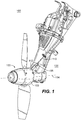
- a partial view of an exemplary embodiment of a RAT deployment system in accordance with the invention is shown in Fig. 1 and is designated generally by reference character 100.
- Other embodiments of the system in accordance with the invention, or aspects thereof, are provided in Figs. 2-3 , as will be described.
- the methods and systems of the invention can be used to ease retraction of a RAT plunger and decrease stress loads on a RAT.
- Fig. 1 shows a ram air turbine deployment system 100 including a turbine 102 which rotates about and defines a rotational axis 104.
- a RAT 100 is deployed in order to produce auxiliary power to an aircraft during flight. Although the deployment is typically done during situations requiring a quick response, it is necessary to wait until the RAT has been fully deployed before the turbine starts spinning in order to avoid striking various components within the hull of an aircraft.
- the turbine 102 includes at least one notch 106 (shown in Fig. 2 and 3 ) located on the inside of the turbine housing 103 therein which receives a plunger 108 which prevents rotation of the turbine 102 when inserted into the notch 106.
- the notch 106 is a cavity within a portion of the turbine 102 that rotates.
- the plunger 108 is quickly removed allowing the turbine 102 to spin freely.
- the plunger moves between a first position 108a (inserted) and a second position 108b (pulled out) by being pulled by a turbine release cable 110.
- Figs. 2 and 3 show the plunger 108 located partially within a bore 112 which protects the plunger 108.
- the bore 112 is attached to a turbine support member 114.
- a first bearing 116 contacts at least a portion of the plunger 108 to reduce friction when the plunger 108 moves between the first position 108a and the second position 108b.
- the bore 112 houses the first bearing 116 between an inner surface 112a the bore and an outer surface of the plunger 108c.
- the first bearing 116 can be a linear bearing elongated along an axis parallel to the movement axis of the plunger 108 from the first position 108a to the second position 108b.
- the coefficient of friction between the plunger 108 and the bearing is below 0.03, and preferably 0.02.
- the plunger 108 is inserted into notch 106 at an angle with the rotational axis 104 of the turbine 102.
- a second bearing 118 can be located within the notch 106.
- the second bearing 118 is a non-linear bearing. It is also considered that a plurality of notches 106 can be distributed around the turbine.
Landscapes
- Engineering & Computer Science (AREA)
- Aviation & Aerospace Engineering (AREA)
- Sustainable Development (AREA)
- Life Sciences & Earth Sciences (AREA)
- Sustainable Energy (AREA)
- Chemical & Material Sciences (AREA)
- Combustion & Propulsion (AREA)
- Mechanical Engineering (AREA)
- General Engineering & Computer Science (AREA)
- Power Engineering (AREA)
- Turbine Rotor Nozzle Sealing (AREA)
- Transmission Devices (AREA)
- Rolling Contact Bearings (AREA)
Abstract
Description
- The present disclosure relates to a ram air turbine deployment, and more particularly to a mechanism for decreasing stress on the ram air turbine cable.
- A variety of devices are used for deploying a ram air turbine (RAT). Current RATs are stopped from rotating while stowed using a plunger that is grounded to a RAT stationary structure or support and interfaces with the turbine driveshaft that is otherwise free to rotate. Once the RAT is deployed, this turbine produces a large amount torque on a turbine release plunger. The force can lead to high forces on the turbine release cable which can, in-turn, lead to cable stretch. This cable stretch can lead to failure to release at a later time. Conventional methods have led to bulkier drive shafts and cables and increased weight because components are sized for these increased loads.
- The conventional methods and systems have generally been considered satisfactory for their intended purpose. However, there is still a need in the art for a RAT release mechanism and method having improved control and a lower stress loads. There also remains a need in the art for such methods and components that are economically viable. The present disclosure may provide a solution for at least one of these remaining challenges.
- A ram air turbine release system includes a turbine defining a rotational axis including at least one notch therein configured to receive a plunger, a plunger configured to prevent rotation of the turbine and to move between a first position and a second position, and a first bearing contacting at least a portion of an outer surface of the plunger configured to reduce friction produced when the plunger moves between the first positon and the second position. A surface of the notch can be angled with respect to the rotational axis.
- The plunger can be partially housed within a bore coupled to a turbine support member. The first bearing can be located within the bore between an inner surface of the bore and an outer surface of the plunger. The first bearing can be a linear bearing elongated along an axis parallel to a primary axis of the plunger. A coefficient of friction between the plunger and a portion of bearing system can be below 0.03.
- A second bearing can be located at least partially within the notch of the turbine. The second bearing is a non-linear bearing. The at least one notch can include a plurality of notches, evenly distributed around the turbine.
- These and other features of the systems and methods of the subject disclosure will become more readily apparent to those skilled in the art from the following detailed description of the preferred embodiments taken in conjunction with the drawings.
- So that those skilled in the art to which the subject invention appertains will readily understand how to make and use the devices and methods of the subject invention without undue experimentation, preferred embodiments thereof will be described in detail herein below with reference to certain figures, wherein:
-
Fig. 1 is a perspective view of a RAT in deployed state; -
Fig. 2 is a side cross-section view ofFig. 1 , showing a plunger and bearings; and -
Fig. 3 is a front cross-section ofFig. 1 , showing the plunger and bearings. - Reference will now be made to the drawings wherein like reference numerals identify similar structural features or aspects of the subject invention. For purposes of explanation and illustration, and not limitation, a partial view of an exemplary embodiment of a RAT deployment system in accordance with the invention is shown in
Fig. 1 and is designated generally byreference character 100. Other embodiments of the system in accordance with the invention, or aspects thereof, are provided inFigs. 2-3 , as will be described. The methods and systems of the invention can be used to ease retraction of a RAT plunger and decrease stress loads on a RAT. -
Fig. 1 shows a ram airturbine deployment system 100 including aturbine 102 which rotates about and defines arotational axis 104. A RAT 100 is deployed in order to produce auxiliary power to an aircraft during flight. Although the deployment is typically done during situations requiring a quick response, it is necessary to wait until the RAT has been fully deployed before the turbine starts spinning in order to avoid striking various components within the hull of an aircraft. Theturbine 102 includes at least one notch 106 (shown inFig. 2 and3 ) located on the inside of theturbine housing 103 therein which receives aplunger 108 which prevents rotation of theturbine 102 when inserted into thenotch 106. Thenotch 106 is a cavity within a portion of theturbine 102 that rotates. After the RAT 100 is fully deployed, theplunger 108 is quickly removed allowing theturbine 102 to spin freely. The plunger moves between afirst position 108a (inserted) and asecond position 108b (pulled out) by being pulled by aturbine release cable 110. -
Figs. 2 and3 show theplunger 108 located partially within abore 112 which protects theplunger 108. Thebore 112 is attached to aturbine support member 114. In order to decrease the stresses on thecable 110 and on theplunger 108 a first bearing 116 contacts at least a portion of theplunger 108 to reduce friction when theplunger 108 moves between thefirst position 108a and thesecond position 108b. Thebore 112 houses the first bearing 116 between aninner surface 112a the bore and an outer surface of theplunger 108c. The first bearing 116 can be a linear bearing elongated along an axis parallel to the movement axis of theplunger 108 from thefirst position 108a to thesecond position 108b. The coefficient of friction between theplunger 108 and the bearing is below 0.03, and preferably 0.02. Theplunger 108 is inserted intonotch 106 at an angle with therotational axis 104 of theturbine 102. A second bearing 118 can be located within thenotch 106. The second bearing 118 is a non-linear bearing. It is also considered that a plurality ofnotches 106 can be distributed around the turbine. - The methods and systems of the present disclosure, as described above and shown in the drawings, provide for a RAT deployment system with superior properties including increased reliability and stability, and reduced size, weight, complexity, and/or cost. While the apparatus and methods of the subject disclosure have been showing and described with reference to embodiments, those skilled in the art will readily appreciate that changes and/or modifications may be made thereto without departing from the scope of the invention as defined by the claims.
Claims (15)
- A ram air turbine deployment system comprising:a turbine (102) defining a rotational axis (104) including at least one notch (106) therein configured to receive a plunger (108);a plunger (108) configured to prevent rotation of the turbine mechanically configured to move between a first position (108a) and a second position (108b); anda first bearing (116) contacting at least a portion of an outer surface of the plunger configured to reduce friction produced when the plunger moves between the first positon and the second position, wherein the first bearing is partially housed within a bore (112) coupled to a turbine .
- The system of claim 1, wherein a surface of the notch is angled with respect to the rotational axis.
- The system of claim 1 or 2, wherein the plunger is partially housed within the borer.
- The system of claim 3, wherein the first bearing (116) is located within the bore (112) between an inner surface of the bore and an outer surface of the plunger.
- The system of claim 4, wherein the first bearing is a linear bearing.
- The system of claim 5, wherein the linear bearing is elongated along an axis parallel to a primary axis of the plunger (108).
- The system of any preceding claim, wherein the bearing system includes a second bearing (118) located at least partially within the notch of the turbine.
- The system of claim 7, wherein the second bearing is a non-linear bearing.
- The system of any preceding claim, wherein the plunger is attached to a turbine release cable (114).
- The system of any preceding claim 1, wherein a coefficient of friction between the plunger and a portion of the bearing is below 0.03.
- The system of claim 1, wherein the at least one notch includes a plurality of notches.
- The system of any preceding claim, where the notches are evenly arranged circumferentially around the turbine.
- The system of any preceding claim, further comprising a plurality of plungers.
- The system of any preceding claim, wherein the plunger and the bearing are metallic.
- The system of any preceding claim, wherein a primary axis of the plunger is angled at a non-zero angle with respect to the rotational axis of the turbine.
Applications Claiming Priority (1)
| Application Number | Priority Date | Filing Date | Title |
|---|---|---|---|
| US16/821,859 US11603211B2 (en) | 2020-03-17 | 2020-03-17 | Ram air turbine rolling element bearing supported turbine release for load reduction |
Publications (2)
| Publication Number | Publication Date |
|---|---|
| EP3882158A1 true EP3882158A1 (en) | 2021-09-22 |
| EP3882158B1 EP3882158B1 (en) | 2023-08-30 |
Family
ID=74947250
Family Applications (1)
| Application Number | Title | Priority Date | Filing Date |
|---|---|---|---|
| EP21163260.9A Active EP3882158B1 (en) | 2020-03-17 | 2021-03-17 | Ram air turbine rolling element bearing supported turbine release for load reduction |
Country Status (2)
| Country | Link |
|---|---|
| US (1) | US11603211B2 (en) |
| EP (1) | EP3882158B1 (en) |
Citations (3)
| Publication number | Priority date | Publication date | Assignee | Title |
|---|---|---|---|---|
| US20120114485A1 (en) * | 2010-11-04 | 2012-05-10 | Hamilton Sundstrand Corporation | Ram air turbine startup |
| US20130287569A1 (en) * | 2012-04-27 | 2013-10-31 | David G. Bannon | Turbine lock plunger for ram air turbine assembly |
| US20140070049A1 (en) * | 2012-09-13 | 2014-03-13 | Hamilton Sundstrand Corporation | Ram Air Turbine Release Cable Assembly |
Family Cites Families (8)
| Publication number | Priority date | Publication date | Assignee | Title |
|---|---|---|---|---|
| US3003748A (en) | 1959-11-17 | 1961-10-10 | United Shoe Machinery Corp | Cable retractor |
| US4717095A (en) * | 1985-06-10 | 1988-01-05 | Sundstrand Corporation | Ram air turbine indexing mechanism |
| US4742976A (en) * | 1985-06-10 | 1988-05-10 | Sundstrand Corporation | Ram air turbine and deployment mechanism |
| US4945979A (en) | 1988-06-23 | 1990-08-07 | Westinghouse Electric Corp. | Robotic arm for delivering a tube plugging tool |
| US6676379B2 (en) * | 2001-12-06 | 2004-01-13 | Honeywell International Inc. | Ram air turbine with speed increasing gearbox |
| US7074010B2 (en) | 2004-10-12 | 2006-07-11 | Hamilton Sundstrand Corporation | RAM air turbine over-speed protector using redundant yoke plate linear bearings |
| US7296970B2 (en) | 2005-06-08 | 2007-11-20 | Hamilton Sundstrand Corporation | Ram air turbine speed sensing ball detent over-speed prevention mechanism |
| DE102013224429A1 (en) | 2013-11-28 | 2015-05-28 | Zf Friedrichshafen Ag | Cable, transmission system and method of making a cable |
-
2020
- 2020-03-17 US US16/821,859 patent/US11603211B2/en active Active
-
2021
- 2021-03-17 EP EP21163260.9A patent/EP3882158B1/en active Active
Patent Citations (3)
| Publication number | Priority date | Publication date | Assignee | Title |
|---|---|---|---|---|
| US20120114485A1 (en) * | 2010-11-04 | 2012-05-10 | Hamilton Sundstrand Corporation | Ram air turbine startup |
| US20130287569A1 (en) * | 2012-04-27 | 2013-10-31 | David G. Bannon | Turbine lock plunger for ram air turbine assembly |
| US20140070049A1 (en) * | 2012-09-13 | 2014-03-13 | Hamilton Sundstrand Corporation | Ram Air Turbine Release Cable Assembly |
Also Published As
| Publication number | Publication date |
|---|---|
| US20210291999A1 (en) | 2021-09-23 |
| US11603211B2 (en) | 2023-03-14 |
| EP3882158B1 (en) | 2023-08-30 |
Similar Documents
| Publication | Publication Date | Title |
|---|---|---|
| US9205923B1 (en) | Manual override cargo unloading system for air cushion supported aircraft cargo loading robot | |
| EP2527664B1 (en) | Ram air turbine deployment actuator having locking means | |
| US11840430B2 (en) | Cable break-away safety device | |
| JP7249440B2 (en) | Spacecraft Multiple Holding/Separating Apparatus and Method for Detaching Spacecraft from Launcher Dispenser to Install Spacecraft Multiple Holding/Separating Apparatus | |
| EP2985472A2 (en) | Stow lock pawl for a rat actuator | |
| US7416392B2 (en) | Stow abort mechanism for a ram air turbine | |
| CN101535635A (en) | Adjustable, self-aligning rotor locking device for an aerogenerator | |
| EP2610168A1 (en) | Adjustable pitch link | |
| US20120114485A1 (en) | Ram air turbine startup | |
| US9598980B2 (en) | Turbine lock plunger for ram air turbine assembly | |
| US20170305003A1 (en) | Extraction device for extracting a trim weight from a rotor blade | |
| US8931734B2 (en) | Ram air turbine release cable assembly | |
| EP3882158B1 (en) | Ram air turbine rolling element bearing supported turbine release for load reduction | |
| EP3772803B1 (en) | Rescue hoist cooling system | |
| EP3196126B1 (en) | Locking and unlocking mechanism | |
| US7306430B2 (en) | Ram air turbine blade rotation over-speed prevention mechanism | |
| US20180245571A1 (en) | Gearbox for a wind turbine | |
| EP3239052B1 (en) | Locking and unlocking mechanism | |
| CN111942573A (en) | Actuator with disengageable output shaft | |
| EP3284677A1 (en) | Locking and unlocking mechanism | |
| EP3715657A1 (en) | Overload clutch assembly for hoist | |
| EP3653496B1 (en) | Sensor for monitoring rotors | |
| EP3882492A1 (en) | Ram air turbine gearbox assembly | |
| EP4257494B1 (en) | Ram air turbine including damping element to vary natural frequency | |
| EP3260375A1 (en) | Actuator release mechanism |
Legal Events
| Date | Code | Title | Description |
|---|---|---|---|
| PUAI | Public reference made under article 153(3) epc to a published international application that has entered the european phase |
Free format text: ORIGINAL CODE: 0009012 |
|
| STAA | Information on the status of an ep patent application or granted ep patent |
Free format text: STATUS: THE APPLICATION HAS BEEN PUBLISHED |
|
| AK | Designated contracting states |
Kind code of ref document: A1 Designated state(s): AL AT BE BG CH CY CZ DE DK EE ES FI FR GB GR HR HU IE IS IT LI LT LU LV MC MK MT NL NO PL PT RO RS SE SI SK SM TR |
|
| STAA | Information on the status of an ep patent application or granted ep patent |
Free format text: STATUS: REQUEST FOR EXAMINATION WAS MADE |
|
| 17P | Request for examination filed |
Effective date: 20220322 |
|
| RBV | Designated contracting states (corrected) |
Designated state(s): AL AT BE BG CH CY CZ DE DK EE ES FI FR GB GR HR HU IE IS IT LI LT LU LV MC MK MT NL NO PL PT RO RS SE SI SK SM TR |
|
| GRAP | Despatch of communication of intention to grant a patent |
Free format text: ORIGINAL CODE: EPIDOSNIGR1 |
|
| STAA | Information on the status of an ep patent application or granted ep patent |
Free format text: STATUS: GRANT OF PATENT IS INTENDED |
|
| INTG | Intention to grant announced |
Effective date: 20230329 |
|
| GRAS | Grant fee paid |
Free format text: ORIGINAL CODE: EPIDOSNIGR3 |
|
| GRAA | (expected) grant |
Free format text: ORIGINAL CODE: 0009210 |
|
| STAA | Information on the status of an ep patent application or granted ep patent |
Free format text: STATUS: THE PATENT HAS BEEN GRANTED |
|
| AK | Designated contracting states |
Kind code of ref document: B1 Designated state(s): AL AT BE BG CH CY CZ DE DK EE ES FI FR GB GR HR HU IE IS IT LI LT LU LV MC MK MT NL NO PL PT RO RS SE SI SK SM TR |
|
| REG | Reference to a national code |
Ref country code: GB Ref legal event code: FG4D |
|
| REG | Reference to a national code |
Ref country code: CH Ref legal event code: EP |
|
| REG | Reference to a national code |
Ref country code: DE Ref legal event code: R096 Ref document number: 602021004598 Country of ref document: DE |
|
| REG | Reference to a national code |
Ref country code: IE Ref legal event code: FG4D |
|
| REG | Reference to a national code |
Ref country code: LT Ref legal event code: MG9D |
|
| REG | Reference to a national code |
Ref country code: NL Ref legal event code: MP Effective date: 20230830 |
|
| REG | Reference to a national code |
Ref country code: AT Ref legal event code: MK05 Ref document number: 1605153 Country of ref document: AT Kind code of ref document: T Effective date: 20230830 |
|
| PG25 | Lapsed in a contracting state [announced via postgrant information from national office to epo] |
Ref country code: GR Free format text: LAPSE BECAUSE OF FAILURE TO SUBMIT A TRANSLATION OF THE DESCRIPTION OR TO PAY THE FEE WITHIN THE PRESCRIBED TIME-LIMIT Effective date: 20231201 |
|
| PG25 | Lapsed in a contracting state [announced via postgrant information from national office to epo] |
Ref country code: IS Free format text: LAPSE BECAUSE OF FAILURE TO SUBMIT A TRANSLATION OF THE DESCRIPTION OR TO PAY THE FEE WITHIN THE PRESCRIBED TIME-LIMIT Effective date: 20231230 |
|
| PG25 | Lapsed in a contracting state [announced via postgrant information from national office to epo] |
Ref country code: SE Free format text: LAPSE BECAUSE OF FAILURE TO SUBMIT A TRANSLATION OF THE DESCRIPTION OR TO PAY THE FEE WITHIN THE PRESCRIBED TIME-LIMIT Effective date: 20230830 Ref country code: RS Free format text: LAPSE BECAUSE OF FAILURE TO SUBMIT A TRANSLATION OF THE DESCRIPTION OR TO PAY THE FEE WITHIN THE PRESCRIBED TIME-LIMIT Effective date: 20230830 Ref country code: NO Free format text: LAPSE BECAUSE OF FAILURE TO SUBMIT A TRANSLATION OF THE DESCRIPTION OR TO PAY THE FEE WITHIN THE PRESCRIBED TIME-LIMIT Effective date: 20231130 Ref country code: LV Free format text: LAPSE BECAUSE OF FAILURE TO SUBMIT A TRANSLATION OF THE DESCRIPTION OR TO PAY THE FEE WITHIN THE PRESCRIBED TIME-LIMIT Effective date: 20230830 Ref country code: LT Free format text: LAPSE BECAUSE OF FAILURE TO SUBMIT A TRANSLATION OF THE DESCRIPTION OR TO PAY THE FEE WITHIN THE PRESCRIBED TIME-LIMIT Effective date: 20230830 Ref country code: IS Free format text: LAPSE BECAUSE OF FAILURE TO SUBMIT A TRANSLATION OF THE DESCRIPTION OR TO PAY THE FEE WITHIN THE PRESCRIBED TIME-LIMIT Effective date: 20231230 Ref country code: HR Free format text: LAPSE BECAUSE OF FAILURE TO SUBMIT A TRANSLATION OF THE DESCRIPTION OR TO PAY THE FEE WITHIN THE PRESCRIBED TIME-LIMIT Effective date: 20230830 Ref country code: GR Free format text: LAPSE BECAUSE OF FAILURE TO SUBMIT A TRANSLATION OF THE DESCRIPTION OR TO PAY THE FEE WITHIN THE PRESCRIBED TIME-LIMIT Effective date: 20231201 Ref country code: FI Free format text: LAPSE BECAUSE OF FAILURE TO SUBMIT A TRANSLATION OF THE DESCRIPTION OR TO PAY THE FEE WITHIN THE PRESCRIBED TIME-LIMIT Effective date: 20230830 Ref country code: AT Free format text: LAPSE BECAUSE OF FAILURE TO SUBMIT A TRANSLATION OF THE DESCRIPTION OR TO PAY THE FEE WITHIN THE PRESCRIBED TIME-LIMIT Effective date: 20230830 |
|
| PG25 | Lapsed in a contracting state [announced via postgrant information from national office to epo] |
Ref country code: PL Free format text: LAPSE BECAUSE OF FAILURE TO SUBMIT A TRANSLATION OF THE DESCRIPTION OR TO PAY THE FEE WITHIN THE PRESCRIBED TIME-LIMIT Effective date: 20230830 Ref country code: NL Free format text: LAPSE BECAUSE OF FAILURE TO SUBMIT A TRANSLATION OF THE DESCRIPTION OR TO PAY THE FEE WITHIN THE PRESCRIBED TIME-LIMIT Effective date: 20230830 |
|
| PG25 | Lapsed in a contracting state [announced via postgrant information from national office to epo] |
Ref country code: ES Free format text: LAPSE BECAUSE OF FAILURE TO SUBMIT A TRANSLATION OF THE DESCRIPTION OR TO PAY THE FEE WITHIN THE PRESCRIBED TIME-LIMIT Effective date: 20230830 |
|
| PG25 | Lapsed in a contracting state [announced via postgrant information from national office to epo] |
Ref country code: SM Free format text: LAPSE BECAUSE OF FAILURE TO SUBMIT A TRANSLATION OF THE DESCRIPTION OR TO PAY THE FEE WITHIN THE PRESCRIBED TIME-LIMIT Effective date: 20230830 Ref country code: RO Free format text: LAPSE BECAUSE OF FAILURE TO SUBMIT A TRANSLATION OF THE DESCRIPTION OR TO PAY THE FEE WITHIN THE PRESCRIBED TIME-LIMIT Effective date: 20230830 Ref country code: ES Free format text: LAPSE BECAUSE OF FAILURE TO SUBMIT A TRANSLATION OF THE DESCRIPTION OR TO PAY THE FEE WITHIN THE PRESCRIBED TIME-LIMIT Effective date: 20230830 Ref country code: EE Free format text: LAPSE BECAUSE OF FAILURE TO SUBMIT A TRANSLATION OF THE DESCRIPTION OR TO PAY THE FEE WITHIN THE PRESCRIBED TIME-LIMIT Effective date: 20230830 Ref country code: DK Free format text: LAPSE BECAUSE OF FAILURE TO SUBMIT A TRANSLATION OF THE DESCRIPTION OR TO PAY THE FEE WITHIN THE PRESCRIBED TIME-LIMIT Effective date: 20230830 Ref country code: CZ Free format text: LAPSE BECAUSE OF FAILURE TO SUBMIT A TRANSLATION OF THE DESCRIPTION OR TO PAY THE FEE WITHIN THE PRESCRIBED TIME-LIMIT Effective date: 20230830 Ref country code: SK Free format text: LAPSE BECAUSE OF FAILURE TO SUBMIT A TRANSLATION OF THE DESCRIPTION OR TO PAY THE FEE WITHIN THE PRESCRIBED TIME-LIMIT Effective date: 20230830 Ref country code: PT Free format text: LAPSE BECAUSE OF FAILURE TO SUBMIT A TRANSLATION OF THE DESCRIPTION OR TO PAY THE FEE WITHIN THE PRESCRIBED TIME-LIMIT Effective date: 20240102 |
|
| PG25 | Lapsed in a contracting state [announced via postgrant information from national office to epo] |
Ref country code: IT Free format text: LAPSE BECAUSE OF FAILURE TO SUBMIT A TRANSLATION OF THE DESCRIPTION OR TO PAY THE FEE WITHIN THE PRESCRIBED TIME-LIMIT Effective date: 20230830 |
|
| REG | Reference to a national code |
Ref country code: DE Ref legal event code: R097 Ref document number: 602021004598 Country of ref document: DE |
|
| PLBE | No opposition filed within time limit |
Free format text: ORIGINAL CODE: 0009261 |
|
| STAA | Information on the status of an ep patent application or granted ep patent |
Free format text: STATUS: NO OPPOSITION FILED WITHIN TIME LIMIT |
|
| PG25 | Lapsed in a contracting state [announced via postgrant information from national office to epo] |
Ref country code: SI Free format text: LAPSE BECAUSE OF FAILURE TO SUBMIT A TRANSLATION OF THE DESCRIPTION OR TO PAY THE FEE WITHIN THE PRESCRIBED TIME-LIMIT Effective date: 20230830 |
|
| 26N | No opposition filed |
Effective date: 20240603 |
|
| REG | Reference to a national code |
Ref country code: CH Ref legal event code: PL |
|
| PG25 | Lapsed in a contracting state [announced via postgrant information from national office to epo] |
Ref country code: BG Free format text: LAPSE BECAUSE OF FAILURE TO SUBMIT A TRANSLATION OF THE DESCRIPTION OR TO PAY THE FEE WITHIN THE PRESCRIBED TIME-LIMIT Effective date: 20230830 |
|
| PG25 | Lapsed in a contracting state [announced via postgrant information from national office to epo] |
Ref country code: LU Free format text: LAPSE BECAUSE OF NON-PAYMENT OF DUE FEES Effective date: 20240317 |
|
| PG25 | Lapsed in a contracting state [announced via postgrant information from national office to epo] |
Ref country code: MC Free format text: LAPSE BECAUSE OF FAILURE TO SUBMIT A TRANSLATION OF THE DESCRIPTION OR TO PAY THE FEE WITHIN THE PRESCRIBED TIME-LIMIT Effective date: 20230830 |
|
| PG25 | Lapsed in a contracting state [announced via postgrant information from national office to epo] |
Ref country code: MC Free format text: LAPSE BECAUSE OF FAILURE TO SUBMIT A TRANSLATION OF THE DESCRIPTION OR TO PAY THE FEE WITHIN THE PRESCRIBED TIME-LIMIT Effective date: 20230830 Ref country code: BG Free format text: LAPSE BECAUSE OF FAILURE TO SUBMIT A TRANSLATION OF THE DESCRIPTION OR TO PAY THE FEE WITHIN THE PRESCRIBED TIME-LIMIT Effective date: 20230830 Ref country code: LU Free format text: LAPSE BECAUSE OF NON-PAYMENT OF DUE FEES Effective date: 20240317 |
|
| REG | Reference to a national code |
Ref country code: BE Ref legal event code: MM Effective date: 20240331 |
|
| PG25 | Lapsed in a contracting state [announced via postgrant information from national office to epo] |
Ref country code: BE Free format text: LAPSE BECAUSE OF NON-PAYMENT OF DUE FEES Effective date: 20240331 |
|
| PG25 | Lapsed in a contracting state [announced via postgrant information from national office to epo] |
Ref country code: IE Free format text: LAPSE BECAUSE OF NON-PAYMENT OF DUE FEES Effective date: 20240317 |
|
| PG25 | Lapsed in a contracting state [announced via postgrant information from national office to epo] |
Ref country code: IE Free format text: LAPSE BECAUSE OF NON-PAYMENT OF DUE FEES Effective date: 20240317 Ref country code: BE Free format text: LAPSE BECAUSE OF NON-PAYMENT OF DUE FEES Effective date: 20240331 Ref country code: CH Free format text: LAPSE BECAUSE OF NON-PAYMENT OF DUE FEES Effective date: 20240331 |
|
| PG25 | Lapsed in a contracting state [announced via postgrant information from national office to epo] |
Ref country code: CY Free format text: LAPSE BECAUSE OF FAILURE TO SUBMIT A TRANSLATION OF THE DESCRIPTION OR TO PAY THE FEE WITHIN THE PRESCRIBED TIME-LIMIT; INVALID AB INITIO Effective date: 20210317 |
|
| PG25 | Lapsed in a contracting state [announced via postgrant information from national office to epo] |
Ref country code: HU Free format text: LAPSE BECAUSE OF FAILURE TO SUBMIT A TRANSLATION OF THE DESCRIPTION OR TO PAY THE FEE WITHIN THE PRESCRIBED TIME-LIMIT; INVALID AB INITIO Effective date: 20210317 |
|
| PG25 | Lapsed in a contracting state [announced via postgrant information from national office to epo] |
Ref country code: TR Free format text: LAPSE BECAUSE OF FAILURE TO SUBMIT A TRANSLATION OF THE DESCRIPTION OR TO PAY THE FEE WITHIN THE PRESCRIBED TIME-LIMIT Effective date: 20230830 |
|
| P01 | Opt-out of the competence of the unified patent court (upc) registered |
Free format text: CASE NUMBER: UPC_APP_0018618_3882158/2025 Effective date: 20251221 |
|
| PGFP | Annual fee paid to national office [announced via postgrant information from national office to epo] |
Ref country code: GB Payment date: 20260220 Year of fee payment: 6 |
|
| PGFP | Annual fee paid to national office [announced via postgrant information from national office to epo] |
Ref country code: DE Payment date: 20260219 Year of fee payment: 6 |
|
| PGFP | Annual fee paid to national office [announced via postgrant information from national office to epo] |
Ref country code: FR Payment date: 20260219 Year of fee payment: 6 |