EP3882079A1 - Vehicle image processing device - Google Patents
Vehicle image processing device Download PDFInfo
- Publication number
- EP3882079A1 EP3882079A1 EP21160294.1A EP21160294A EP3882079A1 EP 3882079 A1 EP3882079 A1 EP 3882079A1 EP 21160294 A EP21160294 A EP 21160294A EP 3882079 A1 EP3882079 A1 EP 3882079A1
- Authority
- EP
- European Patent Office
- Prior art keywords
- image
- vehicle
- user
- video data
- display
- Prior art date
- Legal status (The legal status is an assumption and is not a legal conclusion. Google has not performed a legal analysis and makes no representation as to the accuracy of the status listed.)
- Granted
Links
Images


Classifications
-
- H—ELECTRICITY
- H04—ELECTRIC COMMUNICATION TECHNIQUE
- H04N—PICTORIAL COMMUNICATION, e.g. TELEVISION
- H04N23/00—Cameras or camera modules comprising electronic image sensors; Control thereof
-
- B—PERFORMING OPERATIONS; TRANSPORTING
- B60—VEHICLES IN GENERAL
- B60W—CONJOINT CONTROL OF VEHICLE SUB-UNITS OF DIFFERENT TYPE OR DIFFERENT FUNCTION; CONTROL SYSTEMS SPECIALLY ADAPTED FOR HYBRID VEHICLES; ROAD VEHICLE DRIVE CONTROL SYSTEMS FOR PURPOSES NOT RELATED TO THE CONTROL OF A PARTICULAR SUB-UNIT
- B60W50/00—Details of control systems for road vehicle drive control not related to the control of a particular sub-unit, e.g. process diagnostic or vehicle driver interfaces
- B60W50/08—Interaction between the driver and the control system
- B60W50/14—Means for informing the driver, warning the driver or prompting a driver intervention
-
- G—PHYSICS
- G06—COMPUTING OR CALCULATING; COUNTING
- G06V—IMAGE OR VIDEO RECOGNITION OR UNDERSTANDING
- G06V20/00—Scenes; Scene-specific elements
- G06V20/50—Context or environment of the image
- G06V20/56—Context or environment of the image exterior to a vehicle by using sensors mounted on the vehicle
-
- B—PERFORMING OPERATIONS; TRANSPORTING
- B60—VEHICLES IN GENERAL
- B60R—VEHICLES, VEHICLE FITTINGS, OR VEHICLE PARTS, NOT OTHERWISE PROVIDED FOR
- B60R2300/00—Details of viewing arrangements using cameras and displays, specially adapted for use in a vehicle
- B60R2300/30—Details of viewing arrangements using cameras and displays, specially adapted for use in a vehicle characterised by the type of image processing
-
- B—PERFORMING OPERATIONS; TRANSPORTING
- B60—VEHICLES IN GENERAL
- B60R—VEHICLES, VEHICLE FITTINGS, OR VEHICLE PARTS, NOT OTHERWISE PROVIDED FOR
- B60R2300/00—Details of viewing arrangements using cameras and displays, specially adapted for use in a vehicle
- B60R2300/30—Details of viewing arrangements using cameras and displays, specially adapted for use in a vehicle characterised by the type of image processing
- B60R2300/304—Details of viewing arrangements using cameras and displays, specially adapted for use in a vehicle characterised by the type of image processing using merged images, e.g. merging camera image with stored images
-
- B—PERFORMING OPERATIONS; TRANSPORTING
- B60—VEHICLES IN GENERAL
- B60R—VEHICLES, VEHICLE FITTINGS, OR VEHICLE PARTS, NOT OTHERWISE PROVIDED FOR
- B60R2300/00—Details of viewing arrangements using cameras and displays, specially adapted for use in a vehicle
- B60R2300/30—Details of viewing arrangements using cameras and displays, specially adapted for use in a vehicle characterised by the type of image processing
- B60R2300/306—Details of viewing arrangements using cameras and displays, specially adapted for use in a vehicle characterised by the type of image processing using a re-scaling of images
-
- B—PERFORMING OPERATIONS; TRANSPORTING
- B60—VEHICLES IN GENERAL
- B60R—VEHICLES, VEHICLE FITTINGS, OR VEHICLE PARTS, NOT OTHERWISE PROVIDED FOR
- B60R2300/00—Details of viewing arrangements using cameras and displays, specially adapted for use in a vehicle
- B60R2300/30—Details of viewing arrangements using cameras and displays, specially adapted for use in a vehicle characterised by the type of image processing
- B60R2300/307—Details of viewing arrangements using cameras and displays, specially adapted for use in a vehicle characterised by the type of image processing virtually distinguishing relevant parts of a scene from the background of the scene
-
- B—PERFORMING OPERATIONS; TRANSPORTING
- B60—VEHICLES IN GENERAL
- B60R—VEHICLES, VEHICLE FITTINGS, OR VEHICLE PARTS, NOT OTHERWISE PROVIDED FOR
- B60R2300/00—Details of viewing arrangements using cameras and displays, specially adapted for use in a vehicle
- B60R2300/30—Details of viewing arrangements using cameras and displays, specially adapted for use in a vehicle characterised by the type of image processing
- B60R2300/307—Details of viewing arrangements using cameras and displays, specially adapted for use in a vehicle characterised by the type of image processing virtually distinguishing relevant parts of a scene from the background of the scene
- B60R2300/308—Details of viewing arrangements using cameras and displays, specially adapted for use in a vehicle characterised by the type of image processing virtually distinguishing relevant parts of a scene from the background of the scene by overlaying the real scene, e.g. through a head-up display on the windscreen
-
- B—PERFORMING OPERATIONS; TRANSPORTING
- B60—VEHICLES IN GENERAL
- B60R—VEHICLES, VEHICLE FITTINGS, OR VEHICLE PARTS, NOT OTHERWISE PROVIDED FOR
- B60R2300/00—Details of viewing arrangements using cameras and displays, specially adapted for use in a vehicle
- B60R2300/60—Details of viewing arrangements using cameras and displays, specially adapted for use in a vehicle characterised by monitoring and displaying vehicle exterior scenes from a transformed perspective
-
- B—PERFORMING OPERATIONS; TRANSPORTING
- B60—VEHICLES IN GENERAL
- B60R—VEHICLES, VEHICLE FITTINGS, OR VEHICLE PARTS, NOT OTHERWISE PROVIDED FOR
- B60R2300/00—Details of viewing arrangements using cameras and displays, specially adapted for use in a vehicle
- B60R2300/60—Details of viewing arrangements using cameras and displays, specially adapted for use in a vehicle characterised by monitoring and displaying vehicle exterior scenes from a transformed perspective
- B60R2300/602—Details of viewing arrangements using cameras and displays, specially adapted for use in a vehicle characterised by monitoring and displaying vehicle exterior scenes from a transformed perspective with an adjustable viewpoint
-
- B—PERFORMING OPERATIONS; TRANSPORTING
- B60—VEHICLES IN GENERAL
- B60R—VEHICLES, VEHICLE FITTINGS, OR VEHICLE PARTS, NOT OTHERWISE PROVIDED FOR
- B60R2300/00—Details of viewing arrangements using cameras and displays, specially adapted for use in a vehicle
- B60R2300/60—Details of viewing arrangements using cameras and displays, specially adapted for use in a vehicle characterised by monitoring and displaying vehicle exterior scenes from a transformed perspective
- B60R2300/602—Details of viewing arrangements using cameras and displays, specially adapted for use in a vehicle characterised by monitoring and displaying vehicle exterior scenes from a transformed perspective with an adjustable viewpoint
- B60R2300/605—Details of viewing arrangements using cameras and displays, specially adapted for use in a vehicle characterised by monitoring and displaying vehicle exterior scenes from a transformed perspective with an adjustable viewpoint the adjustment being automatic
-
- B—PERFORMING OPERATIONS; TRANSPORTING
- B60—VEHICLES IN GENERAL
- B60R—VEHICLES, VEHICLE FITTINGS, OR VEHICLE PARTS, NOT OTHERWISE PROVIDED FOR
- B60R2300/00—Details of viewing arrangements using cameras and displays, specially adapted for use in a vehicle
- B60R2300/70—Details of viewing arrangements using cameras and displays, specially adapted for use in a vehicle characterised by an event-triggered choice to display a specific image among a selection of captured images
-
- B—PERFORMING OPERATIONS; TRANSPORTING
- B60—VEHICLES IN GENERAL
- B60R—VEHICLES, VEHICLE FITTINGS, OR VEHICLE PARTS, NOT OTHERWISE PROVIDED FOR
- B60R2300/00—Details of viewing arrangements using cameras and displays, specially adapted for use in a vehicle
- B60R2300/80—Details of viewing arrangements using cameras and displays, specially adapted for use in a vehicle characterised by the intended use of the viewing arrangement
-
- B—PERFORMING OPERATIONS; TRANSPORTING
- B60—VEHICLES IN GENERAL
- B60W—CONJOINT CONTROL OF VEHICLE SUB-UNITS OF DIFFERENT TYPE OR DIFFERENT FUNCTION; CONTROL SYSTEMS SPECIALLY ADAPTED FOR HYBRID VEHICLES; ROAD VEHICLE DRIVE CONTROL SYSTEMS FOR PURPOSES NOT RELATED TO THE CONTROL OF A PARTICULAR SUB-UNIT
- B60W50/00—Details of control systems for road vehicle drive control not related to the control of a particular sub-unit, e.g. process diagnostic or vehicle driver interfaces
- B60W50/08—Interaction between the driver and the control system
- B60W50/14—Means for informing the driver, warning the driver or prompting a driver intervention
- B60W2050/146—Display means
-
- B—PERFORMING OPERATIONS; TRANSPORTING
- B60—VEHICLES IN GENERAL
- B60W—CONJOINT CONTROL OF VEHICLE SUB-UNITS OF DIFFERENT TYPE OR DIFFERENT FUNCTION; CONTROL SYSTEMS SPECIALLY ADAPTED FOR HYBRID VEHICLES; ROAD VEHICLE DRIVE CONTROL SYSTEMS FOR PURPOSES NOT RELATED TO THE CONTROL OF A PARTICULAR SUB-UNIT
- B60W2420/00—Indexing codes relating to the type of sensors based on the principle of their operation
- B60W2420/40—Photo, light or radio wave sensitive means, e.g. infrared sensors
- B60W2420/403—Image sensing, e.g. optical camera
Definitions
- the present invention relates to a vehicle image processing device that images and displays the surrounding scenery visible from a vehicle interior.
- a vehicle ambient video providing device that converts a video captured by an image pickup device into coordinates based on acquired position information on a viewpoint and information on a setting state of a liquid crystal display such that the same video as a case where a vehicle exterior is viewed through an installation area of the liquid crystal display from a position of a driver's viewpoint is displayed on the liquid crystal display (see, for example, Patent Literature 1: JP 2007-96638 A ).
- this vehicle ambient video providing device it is possible to display a video corresponding to the scenery, which is supposed to be visible in a line-of-sight direction of the driver, on the liquid crystal display.
- Patent Literature 1 JP 2007-96638 A
- the content of the video changes from moment to moment, which causes a problem that it is not easy to grasp the content.
- an object closer to the vehicle stays within a display range for a shorter period of time, and the object disappears immediately even if the driver or the like tries to confirm the object, so that it is difficult to confirm the object within the display range.
- the present invention has been made in view of these points, and an object thereof is to provide a vehicle image processing device capable of confirming an object included in a range visible to a user.
- a vehicle image processing device includes: an imaging means configured to image surroundings of a vehicle and output video data; an image extraction means configured to extract an image from the video data when a predetermined operation for instructing image acquisition is performed; an image processing means configured to process the image extracted by the image extraction means in accordance with a field of view of a user in a vehicle interior; and an image display means configured to display the image processed by the image processing means on a screen arranged at a position aligned with a line of sight of the user.
- an image including this object can be displayed at the position aligned with the line of sight of the user, and thus, it becomes easy to confirm the object included in a range visible to the user.
- a video data storage means configured to store the video data obtained by imaging of the above-described imaging means for a predetermined time
- the image extraction means extracts an image from the video data stored by the video data storage means. Since the video data is stored to perform the extraction of the image, it is possible to avoid a situation where an object to be desirably confirmed is not imaged in time.
- the above-described image extraction means changes a timing of extracting an image from the video data based on a traveling speed of the vehicle. As a result, it is possible to prevent the object to be desirably confirmed from being out of an imaging range due to the delay in operation of the user.
- the above-described image extraction means changes a timing of extracting an image from the video data based on an instruction of the user. As a result, it is possible to retroactively confirm the object entering the field of view.
- a line-of-sight detection means configured to detect the line of sight of the user
- the image processing means generates an image corresponding to the field of view of the user based on the line of sight detected by the line-of-sight detection means. Since the image is extracted, processed, and displayed in accordance with a direction in which the user is facing, it is possible to reproduce the image in a range actually visible that is included in the user's field of view.
- an image recognition means configured to perform image recognition on the image displayed by the above-described image display means and extract a partial image included in the image and an information acquisition means configured to acquire information on the partial image extracted by the image recognition means is provided, and the image display means displays the information acquired by the information acquisition means on the screen in association with the partial image.
- the above-described image display means displays the partial image for which the information has been acquired by the information acquisition means in a distinguishable form, and displays the information acquired by the information acquisition means regarding the partial image for which the display of the information has been instructed by the user.
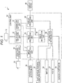
- Fig. 1 is a diagram illustrating a configuration of the vehicle image processing device according to an embodiment.
- a vehicle image processing device 1 of the present embodiment illustrated in Fig. 1 displays an image, similar to, for example, the scenery viewed through a window by a passenger on a rear seat of a vehicle, on this window, and stops the display of the image (moving image) if necessary and provides information on an object (building or the like) as each display element included in this image.
- the vehicle image processing device 1 includes cameras 10 and 12, video data storage unit 20, vehicle speed detection unit 30, a host vehicle position/direction detection unit 32, a display device 40, a map database (DB) 50, a POI DB 52, a general-purpose DB 54, and a control unit 60.
- DB map database
- the camera 10 images the surroundings of the vehicle and outputs video data (moving image).
- the camera 10 is attached to a right side surface of the vehicle and images a wide range of scenery spreading to the right side of the vehicle.
- the camera 12 is installed in a vehicle interior and images a face of a user.
- the video data storage unit 20 records the video data output from the camera 10 for a predetermined time.
- the latest video data for the predetermined time is recorded in the video data storage unit 20, and the previous video data is erased (overwritten).
- the vehicle speed detection unit 30 detects a speed (vehicle speed) of the vehicle.
- the host vehicle position/direction detection unit 32 detects a position and a direction of the vehicle.
- a detection method it is possible to consider a case of using a GPS receiver, a case of using an autonomous navigation sensor, or a case of using a combination of these.
- the display device 40 displays an image (moving image or still image) on the window of the rear seat (window of a rear door).
- the display device 40 is implemented by projecting an image on a window glass with variable transparency, which is called a smart window, or by using a transparent organic EL display or a transparent inorganic EL display.
- the map DB 50 stores map data such as roads and surrounding terrain thereof, and locations of facilities.
- the POI DB 52 stores detailed information on facilities as points of interest (POIs) and natural objects (mountains and the like). This POI DB 52 may be included in the map DB 50.
- the general-purpose DB 54 stores detailed information on various objects included in the user's field of view. For example, information on each object other than (or duplicated with) the facilities and the natural objects stored in the POI DB 52 is included. Each object includes a wide range of material objects other than POIs whose information has been stored in the POI DB 52. This general-purpose DB 54 may be included in the POI DB 52.
- the control unit 60 controls the entire vehicle image processing device 1, and performs an operation of displaying an image captured by the camera 10 on the display device 40 and displaying information on POIs and various objects included in the image.
- the control unit 60 includes an image extraction unit 61, a line-of-sight detection unit 62, an image processing unit 63, a display processing unit 64, an image recognition unit 65, an information retrieval unit 66, and an operation detection unit 67.
- the control unit 60 can implement these various functions by executing a predetermined operation program using a CPU, a ROM, a RAM, and the like.
- the image extraction unit 61 extracts an image from the video data stored in the video data storage unit 20 when a predetermined operation (described later) is performed by the user.
- the line-of-sight detection unit 62 detects a position of user's eyes and a viewing direction (a position of a viewpoint and a direction of a line of sight) based on a face image of the user captured by the camera 12.
- the image processing unit 63 processes the image extracted by the image extraction unit 61 in accordance with the user's field of view. Specifically, the image processing unit 63 performs viewpoint conversion on the image extracted by the image extraction unit 61 to generate an image corresponding to the scenery that the user can view through the screen of the display device 40.
- the display processing unit 64 displays the image generated by the image processing unit 63 on the screen (screen of the display device 40) arranged at a position aligned with the line of sight of the user.
- the image recognition unit 65 performs image recognition on the image displayed on the screen of the display device 40 generated by the image processing unit 63, and extracts a partial image included in this image.
- the information retrieval unit 66 uses the map DB 50, the POI DB 52, and the general-purpose DB 54 to retrieve and acquire detailed information on an object corresponding to the partial image extracted by the image recognition of the image recognition unit 65. Note that this retrieval may be performed by requesting an external search server connected via the Internet.
- the operation detection unit 67 detects an operation performed by the user. For example, it is possible to consider a case where the screen of the display device 40 is included in an imaging range of the camera 12 to detect an operation of pressing an operation button on the screen by the user and a case where a transparent touch panel is arranged on the screen of the display device 40 to detect the operation of pressing the operation button on the screen.
- the above-described camera 10 corresponds to an imaging means
- the image extraction unit 61 corresponds to an image extraction means
- the image processing unit 63 corresponds to an image processing means
- the display processing unit 64 and the display device 40 correspond to an image display means
- the video data storage unit 20 corresponds to a video data storage means
- the camera 12 and the line-of-sight detection unit 62 correspond to a line-of-sight detection means
- the image recognition unit 65 corresponds to an image recognition means
- the information retrieval unit 66 corresponds to an information acquisition means.
- the vehicle image processing device 1 has the above configuration. Next, the operation thereof will be described.
- Fig. 2 is a flowchart illustrating an operation procedure for displaying an image, similar to the scenery visible to the user through a window of a vehicle, on the window according to an embodiment.
- an operation of storing the video data obtained by imaging of the camera 10 in the video data storage unit 20 is performed.
- the image extraction unit 61 determines whether the user has performed a predetermined operation of instructing acquisition and display of an image, for example, whether a "Capture” button displayed on a part of the screen using the window glass is pressed by the user's finger (touched by the user's finger) (Step 100). When the "Capture” button is not pressed, a negative determination is made, and this determination is repeatedly performed.
- Step 100 the image extraction unit 61 extracts an image corresponding to a timing when the "Capture” button has been pressed from the video data stored in the video data storage unit 20 (Step 102). There is a time lag between recognition of the scenery of interest by the user having viewed the outside scenery through the vehicle window and pressing of the "Capture” button. The image extraction unit 61 determines one image to be extracted from the video data in consideration of this time lag and the vehicle speed at that time.
- the image processing unit 63 performs viewpoint conversion or the like on the extracted image and processes the converted image in accordance with the user's field of view (Step 104).
- the display processing unit 64 displays the processed image on the screen (window glass) of the display device 40 (Step 106). It is possible to reproduce the scenery that has been viewed at the location where the vehicle has passed in an instant as the vehicle traveled by viewing the image displayed in this manner, and thus, the user can confirm various objects and the like entering the field of view at that time.
- the predetermined operation pressing of the "Capture” button
- an image including this object can be displayed at the position aligned with the line of sight of the user.
- the captured video data is stored, and then, the extraction of the image is performed, so that it is possible to avoid a situation where an object to be desirably confirmed is not imaged in time.
- the timing of extracting an image from the video data is changed based on a traveling speed of the vehicle, so that it is possible to prevent the object to be desirably confirmed from being out of the imaging range due to the delay in operation of the user.
- the line-of-sight detection unit 62 detects the viewpoint position and the direction of the line of sight, and the image is extracted, processed, and displayed in accordance with a direction in which the user is facing. Thus, it is possible to reliably reproduce the image in the range actually visible that is included in the user's field of view.
- Fig. 3 is a flowchart illustrating an operation procedure of a modification in which image recognition is performed on an image displayed on a window of a vehicle according to an embodiment.
- the operation procedure illustrated in Fig. 3 is different from the operation procedure illustrated in Fig. 2 in terms that Steps 110, 112, 114, 116, and 118 are added next to Step 106. Each of these added steps will be described hereinafter.
- the image recognition unit 65 After the processed screen is displayed (Step 106) (or in parallel to or prior to the display operation), the image recognition unit 65 performs image recognition on the displayed image, and extracts partial images corresponding to a POI and various other objects included in this image (Step 110).
- the information retrieval unit 66 acquires detailed information of objects corresponding to the partial images extracted by the image recognition using the map DB 50, the POI DB 52, and the general-purpose DB 54 (Step 112).
- the information retrieval unit 66 sends an instruction for highlighting the partial images for which the detailed information has been obtained to the display processing unit 64 to highlight these partial images (Step 114).
- the corresponding partial images are displayed in a form that can be distinguished from others by highlighting or by adding a special color.
- the information retrieval unit 66 determines whether any of these highlighted partial images has been instructed by the user (Step 116). When no instruction operation is performed by the user, a negative determination is made, and this determination is repeatedly performed.
- the information retrieval unit 66 displays detailed information corresponding to the instructed partial image (Step 118). For example, a window containing a detailed description is displayed at an adjacent position of this partial image.
- the detailed information on the partial image extracted by the image recognition is displayed in this manner, it is possible to acquire information on an object included in the user's field of view without performing a complicated operation.
- the partial image for which the detailed information has been acquired is displayed in a distinguishable form, and the detailed information is displayed when the user instructs the display of the information.
- the information that the user desires to view while preventing deterioration in visibility due to too much information within the screen.
- the present invention is not limited to the above-described embodiment, and various kinds of modifications can be made within the scope of the gist of the present invention.
- the timing of extracting the image from the video data is determined according to the vehicle speed or the like in the above-described embodiment, but may be changed based on an instruction of the user.
- he processed image is displayed in Step 106 illustrated in Fig.
- Steps 104 and 106 are repeated by shifting the image extraction timing back and forth in accordance with the number of pressing operations when this button is pressed by the user.
- the corresponding image is displayed by pressing the "Capture” button first in the above-described embodiment, but an instruction may be given with voice, instead of this pressing operation.
- an instruction may be given with voice, instead of this pressing operation.
- voice recognition processing it is possible to consider a case where "capture" uttered by the user is determined by voice recognition processing and extraction of an image is performed.
- the viewpoint position and the direction of the field of view of the user are detected from the user's face image captured by the camera 12, and image processing such as the viewpoint conversion is performed by the image processing unit 63 in the above-described embodiment.
- image processing may be performed using fixed viewpoint position and line-of-sight direction assuming that the user sits at a predetermined position and views the outside scenery through the window glass.
- an image including this object can be displayed at the position aligned with the line of sight of the user.
Landscapes
- Engineering & Computer Science (AREA)
- Automation & Control Theory (AREA)
- Mechanical Engineering (AREA)
- Human Computer Interaction (AREA)
- Transportation (AREA)
- Multimedia (AREA)
- Physics & Mathematics (AREA)
- General Physics & Mathematics (AREA)
- Theoretical Computer Science (AREA)
- Signal Processing (AREA)
- Closed-Circuit Television Systems (AREA)
- Image Analysis (AREA)
- Fittings On The Vehicle Exterior For Carrying Loads, And Devices For Holding Or Mounting Articles (AREA)
- Image Processing (AREA)
Abstract
Description
- The present invention relates to a vehicle image processing device that images and displays the surrounding scenery visible from a vehicle interior.
- Conventionally, there is known a vehicle ambient video providing device that converts a video captured by an image pickup device into coordinates based on acquired position information on a viewpoint and information on a setting state of a liquid crystal display such that the same video as a case where a vehicle exterior is viewed through an installation area of the liquid crystal display from a position of a driver's viewpoint is displayed on the liquid crystal display (see, for example, Patent Literature 1:
JP 2007-96638 A - By the way, in the above-described vehicle ambient video providing device disclosed in Patent Literature 1:
JP 2007-96638 A - The present invention has been made in view of these points, and an object thereof is to provide a vehicle image processing device capable of confirming an object included in a range visible to a user.
- The invention relates to a vehicle image processing device according to the appended claims. Embodiments are disclosed in the dependent claims. According to an aspect of the invention a vehicle image processing device includes: an imaging means configured to image surroundings of a vehicle and output video data; an image extraction means configured to extract an image from the video data when a predetermined operation for instructing image acquisition is performed; an image processing means configured to process the image extracted by the image extraction means in accordance with a field of view of a user in a vehicle interior; and an image display means configured to display the image processed by the image processing means on a screen arranged at a position aligned with a line of sight of the user. As a predetermined operation is performed when an object that the user desires to confirm enters the field of view, an image including this object can be displayed at the position aligned with the line of sight of the user, and thus, it becomes easy to confirm the object included in a range visible to the user.
- In addition, according to an embodiment a video data storage means configured to store the video data obtained by imaging of the above-described imaging means for a predetermined time is provided, and the image extraction means extracts an image from the video data stored by the video data storage means. Since the video data is stored to perform the extraction of the image, it is possible to avoid a situation where an object to be desirably confirmed is not imaged in time.
- In addition, according to an embodiment the above-described image extraction means changes a timing of extracting an image from the video data based on a traveling speed of the vehicle. As a result, it is possible to prevent the object to be desirably confirmed from being out of an imaging range due to the delay in operation of the user.
- In addition, according to an embodiment the above-described image extraction means changes a timing of extracting an image from the video data based on an instruction of the user. As a result, it is possible to retroactively confirm the object entering the field of view.
- In addition, according to an embodiment a line-of-sight detection means configured to detect the line of sight of the user is provided, and the image processing means generates an image corresponding to the field of view of the user based on the line of sight detected by the line-of-sight detection means. Since the image is extracted, processed, and displayed in accordance with a direction in which the user is facing, it is possible to reproduce the image in a range actually visible that is included in the user's field of view.
- In addition, according to an embodiment an image recognition means configured to perform image recognition on the image displayed by the above-described image display means and extract a partial image included in the image and an information acquisition means configured to acquire information on the partial image extracted by the image recognition means is provided, and the image display means displays the information acquired by the information acquisition means on the screen in association with the partial image. As a result, it is possible to acquire information on the object included in the user's field of view without performing a complicated operation.
- In addition, according to an embodiment the above-described image display means displays the partial image for which the information has been acquired by the information acquisition means in a distinguishable form, and displays the information acquired by the information acquisition means regarding the partial image for which the display of the information has been instructed by the user. As a result, it is possible to promptly display information that the user desires to view while preventing deterioration in visibility due to too much information within the screen.
-
Fig. 1 is a diagram illustrating a configuration of a vehicle image processing device according to an embodiment. -
Fig. 2 is a flowchart illustrating an operation procedure for displaying an image, similar to the scenery visible to a user through a window of a vehicle, on the window according to an embodiment. -
Fig. 3 is a flowchart illustrating an operation procedure of a modification in which image recognition is performed on an image displayed on a window of a vehicle according to an embodiment. - Hereinafter, a vehicle image processing device according to embodiments of the present invention will be described with reference to the drawings.
-
Fig. 1 is a diagram illustrating a configuration of the vehicle image processing device according to an embodiment. A vehicle image processing device 1 of the present embodiment illustrated inFig. 1 displays an image, similar to, for example, the scenery viewed through a window by a passenger on a rear seat of a vehicle, on this window, and stops the display of the image (moving image) if necessary and provides information on an object (building or the like) as each display element included in this image. For this purpose, the vehicle image processing device 1 includescameras data storage unit 20, vehiclespeed detection unit 30, a host vehicle position/direction detection unit 32, adisplay device 40, a map database (DB) 50, a POIDB 52, a general-purpose DB 54, and acontrol unit 60. - The
camera 10 images the surroundings of the vehicle and outputs video data (moving image). For example, thecamera 10 is attached to a right side surface of the vehicle and images a wide range of scenery spreading to the right side of the vehicle. Thecamera 12 is installed in a vehicle interior and images a face of a user. - The video
data storage unit 20 records the video data output from thecamera 10 for a predetermined time. The latest video data for the predetermined time is recorded in the videodata storage unit 20, and the previous video data is erased (overwritten). - The vehicle
speed detection unit 30 detects a speed (vehicle speed) of the vehicle. - The host vehicle position/
direction detection unit 32 detects a position and a direction of the vehicle. As a detection method, it is possible to consider a case of using a GPS receiver, a case of using an autonomous navigation sensor, or a case of using a combination of these. - The
display device 40 displays an image (moving image or still image) on the window of the rear seat (window of a rear door). For example, thedisplay device 40 is implemented by projecting an image on a window glass with variable transparency, which is called a smart window, or by using a transparent organic EL display or a transparent inorganic EL display. - The map DB 50 stores map data such as roads and surrounding terrain thereof, and locations of facilities.
- The POI DB 52 stores detailed information on facilities as points of interest (POIs) and natural objects (mountains and the like). This POI
DB 52 may be included in themap DB 50. - The general-
purpose DB 54 stores detailed information on various objects included in the user's field of view. For example, information on each object other than (or duplicated with) the facilities and the natural objects stored in the POI DB 52 is included. Each object includes a wide range of material objects other than POIs whose information has been stored in the POIDB 52. This general-purpose DB 54 may be included in the POIDB 52. - The
control unit 60 controls the entire vehicle image processing device 1, and performs an operation of displaying an image captured by thecamera 10 on thedisplay device 40 and displaying information on POIs and various objects included in the image. For this purpose, thecontrol unit 60 includes animage extraction unit 61, a line-of-sight detection unit 62, animage processing unit 63, adisplay processing unit 64, animage recognition unit 65, aninformation retrieval unit 66, and anoperation detection unit 67. Thecontrol unit 60 can implement these various functions by executing a predetermined operation program using a CPU, a ROM, a RAM, and the like. - The
image extraction unit 61 extracts an image from the video data stored in the videodata storage unit 20 when a predetermined operation (described later) is performed by the user. - The line-of-
sight detection unit 62 detects a position of user's eyes and a viewing direction (a position of a viewpoint and a direction of a line of sight) based on a face image of the user captured by thecamera 12. - The
image processing unit 63 processes the image extracted by theimage extraction unit 61 in accordance with the user's field of view. Specifically, theimage processing unit 63 performs viewpoint conversion on the image extracted by theimage extraction unit 61 to generate an image corresponding to the scenery that the user can view through the screen of thedisplay device 40. - The
display processing unit 64 displays the image generated by theimage processing unit 63 on the screen (screen of the display device 40) arranged at a position aligned with the line of sight of the user. - The
image recognition unit 65 performs image recognition on the image displayed on the screen of thedisplay device 40 generated by theimage processing unit 63, and extracts a partial image included in this image. - The
information retrieval unit 66 uses themap DB 50, the POIDB 52, and the general-purpose DB 54 to retrieve and acquire detailed information on an object corresponding to the partial image extracted by the image recognition of theimage recognition unit 65. Note that this retrieval may be performed by requesting an external search server connected via the Internet. - The
operation detection unit 67 detects an operation performed by the user. For example, it is possible to consider a case where the screen of thedisplay device 40 is included in an imaging range of thecamera 12 to detect an operation of pressing an operation button on the screen by the user and a case where a transparent touch panel is arranged on the screen of thedisplay device 40 to detect the operation of pressing the operation button on the screen. - The above-described
camera 10 corresponds to an imaging means, theimage extraction unit 61 corresponds to an image extraction means, theimage processing unit 63 corresponds to an image processing means, thedisplay processing unit 64 and thedisplay device 40 correspond to an image display means, the videodata storage unit 20 corresponds to a video data storage means, thecamera 12 and the line-of-sight detection unit 62 correspond to a line-of-sight detection means, theimage recognition unit 65 corresponds to an image recognition means, and theinformation retrieval unit 66 corresponds to an information acquisition means. - The vehicle image processing device 1 according to the present embodiment has the above configuration. Next, the operation thereof will be described.
-
Fig. 2 is a flowchart illustrating an operation procedure for displaying an image, similar to the scenery visible to the user through a window of a vehicle, on the window according to an embodiment. In parallel with this operation procedure, an operation of storing the video data obtained by imaging of thecamera 10 in the videodata storage unit 20 is performed. - The
image extraction unit 61 determines whether the user has performed a predetermined operation of instructing acquisition and display of an image, for example, whether a "Capture" button displayed on a part of the screen using the window glass is pressed by the user's finger (touched by the user's finger) (Step 100). When the "Capture" button is not pressed, a negative determination is made, and this determination is repeatedly performed. - In addition, when the "Capture" button is pressed, an affirmative determination is made in the determination in
Step 100. Next, theimage extraction unit 61 extracts an image corresponding to a timing when the "Capture" button has been pressed from the video data stored in the video data storage unit 20 (Step 102). There is a time lag between recognition of the scenery of interest by the user having viewed the outside scenery through the vehicle window and pressing of the "Capture" button. Theimage extraction unit 61 determines one image to be extracted from the video data in consideration of this time lag and the vehicle speed at that time. - Next, the
image processing unit 63 performs viewpoint conversion or the like on the extracted image and processes the converted image in accordance with the user's field of view (Step 104). Thedisplay processing unit 64 displays the processed image on the screen (window glass) of the display device 40 (Step 106). It is possible to reproduce the scenery that has been viewed at the location where the vehicle has passed in an instant as the vehicle traveled by viewing the image displayed in this manner, and thus, the user can confirm various objects and the like entering the field of view at that time. - In this manner, in the vehicle image processing device 1 of the present embodiment, the predetermined operation (pressing of the "Capture" button) is performed when an object that the user desires to confirm enters the field of view, and an image including this object can be displayed at the position aligned with the line of sight of the user. Thus, it becomes easy to confirm the object included in a range visible to the user. In particular, the captured video data is stored, and then, the extraction of the image is performed, so that it is possible to avoid a situation where an object to be desirably confirmed is not imaged in time. In addition, the timing of extracting an image from the video data is changed based on a traveling speed of the vehicle, so that it is possible to prevent the object to be desirably confirmed from being out of the imaging range due to the delay in operation of the user.
- In addition, the line-of-
sight detection unit 62 detects the viewpoint position and the direction of the line of sight, and the image is extracted, processed, and displayed in accordance with a direction in which the user is facing. Thus, it is possible to reliably reproduce the image in the range actually visible that is included in the user's field of view. -
Fig. 3 is a flowchart illustrating an operation procedure of a modification in which image recognition is performed on an image displayed on a window of a vehicle according to an embodiment. The operation procedure illustrated inFig. 3 is different from the operation procedure illustrated inFig. 2 in terms that Steps 110, 112, 114, 116, and 118 are added next to Step 106. Each of these added steps will be described hereinafter. - After the processed screen is displayed (Step 106) (or in parallel to or prior to the display operation), the
image recognition unit 65 performs image recognition on the displayed image, and extracts partial images corresponding to a POI and various other objects included in this image (Step 110). - In addition, the
information retrieval unit 66 acquires detailed information of objects corresponding to the partial images extracted by the image recognition using themap DB 50, thePOI DB 52, and the general-purpose DB 54 (Step 112). - Next, the
information retrieval unit 66 sends an instruction for highlighting the partial images for which the detailed information has been obtained to thedisplay processing unit 64 to highlight these partial images (Step 114). For example, the corresponding partial images are displayed in a form that can be distinguished from others by highlighting or by adding a special color. - Next, the
information retrieval unit 66 determines whether any of these highlighted partial images has been instructed by the user (Step 116). When no instruction operation is performed by the user, a negative determination is made, and this determination is repeatedly performed. - In addition, when any of the highlighted partial images is instructed by the user, an affirmative determination is made in the determination in
Step 116. Theinformation retrieval unit 66 displays detailed information corresponding to the instructed partial image (Step 118). For example, a window containing a detailed description is displayed at an adjacent position of this partial image. - Since the detailed information on the partial image extracted by the image recognition is displayed in this manner, it is possible to acquire information on an object included in the user's field of view without performing a complicated operation. In addition, the partial image for which the detailed information has been acquired is displayed in a distinguishable form, and the detailed information is displayed when the user instructs the display of the information. Thus, it is possible to promptly display the information that the user desires to view while preventing deterioration in visibility due to too much information within the screen.
- Note that the present invention is not limited to the above-described embodiment, and various kinds of modifications can be made within the scope of the gist of the present invention. For example, the timing of extracting the image from the video data is determined according to the vehicle speed or the like in the above-described embodiment, but may be changed based on an instruction of the user. There is individual difference in time between recognition of the scenery of interest and pressing of the "Capture" button depending on users, and thus, the practicality can be further enhanced if a deviation of the image extraction timing caused by this individual difference can be adjusted. For example, he processed image is displayed in
Step 106 illustrated inFig. 2 , a button that shifts the timing of extracting the image the from video data back and forth in units of seconds is displayed along with this display, and the operations inSteps - In addition, the corresponding image is displayed by pressing the "Capture" button first in the above-described embodiment, but an instruction may be given with voice, instead of this pressing operation. For example, it is possible to consider a case where "capture" uttered by the user is determined by voice recognition processing and extraction of an image is performed.
- In addition, the viewpoint position and the direction of the field of view of the user are detected from the user's face image captured by the
camera 12, and image processing such as the viewpoint conversion is performed by theimage processing unit 63 in the above-described embodiment. However, image processing may be performed using fixed viewpoint position and line-of-sight direction assuming that the user sits at a predetermined position and views the outside scenery through the window glass. - As described above, according to the present invention, as a predetermined operation is performed when an object that the user desires to confirm enters the field of view, an image including this object can be displayed at the position aligned with the line of sight of the user. Thus, it becomes easy to confirm the object included in a range visible to the user.
-
- 1
- vehicle image processing device
- 10, 12
- camera
- 20
- video data storage unit
- 30
- vehicle speed detection unit
- 32
- host vehicle position/direction detection unit
- 40
- display device
- 50
- map DB
- 52
- POI DB
- 54
- general-purpose DB
- 60
- control unit
- 61
- image extraction unit
- 62
- line-of-sight detection unit
- 63
- image processing unit
- 64
- display processing unit
- 65
- image recognition unit
- 66
- information retrieval unit
- 67
- operation detection unit
Claims (7)
- A vehicle image processing device (1) comprising:an imaging means (10) configured to image surroundings of a vehicle and output video data;an image extraction means (61) configured to extract an image from the video data when a predetermined operation for instructing image acquisition is performed;an image processing means (63) configured to process the image extracted by the image extraction means (61) in accordance with a field of view of a user in a vehicle interior; andan image display means (64, 40) configured to display the image processed by the image processing means (64) on a screen arranged at a position aligned with a line of sight of the user.
- The vehicle image processing device (1) according to claim 1, further comprising
a video data storage means (20) configured to store the video data obtained by imaging of the imaging means (10) for a predetermined time, wherein
the image extraction means (61) is configured to extract an image from the video data stored by the video data storage means (20). - The vehicle image processing device (1) according to claim lor 2, wherein
the image extraction means (61) is configured to change a timing of extracting an image from the video data based on a traveling speed of the vehicle. - The vehicle image processing device (1) according to claim 1 or 2, wherein
the image extraction means (61) is configured to change a timing of extracting an image from the video data based on an instruction of the user. - The vehicle image processing device (1) according to any one of claims 1 to 4, further comprising
a line-of-sight detection means (12, 62) configured to detect the line of sight of the user, wherein
the image processing means (63) is configured to generate an image corresponding to the field of view of the user based on the line of sight detected by the line-of-sight detection means (12, 62). - The vehicle image processing device (1) according to any one of claims 1 to 5, further comprising:an image recognition means (65) configured to perform image recognition on the image displayed by the image display means (64, 40) and extract a partial image included in the image; andan information acquisition means (66) configured to acquire information on the partial image extracted by the image recognition means (65), whereinthe image display means (64, 40) is configured to display the information acquired by the information acquisition means (66) on the screen in association with the partial image.
- The vehicle image processing device (1) according to claim 6, wherein
the image display means (64, 40) is configured to display the partial image for which the information has been acquired by the information acquisition means (66) in a distinguishable form, and to display the information acquired by the information acquisition means (66) regarding the partial image for which the display of the information has been instructed by the user.
Applications Claiming Priority (1)
| Application Number | Priority Date | Filing Date | Title |
|---|---|---|---|
| JP2020050335A JP7442933B2 (en) | 2020-03-20 | 2020-03-20 | Vehicle image processing device |
Publications (2)
| Publication Number | Publication Date |
|---|---|
| EP3882079A1 true EP3882079A1 (en) | 2021-09-22 |
| EP3882079B1 EP3882079B1 (en) | 2022-12-21 |
Family
ID=74856664
Family Applications (1)
| Application Number | Title | Priority Date | Filing Date |
|---|---|---|---|
| EP21160294.1A Active EP3882079B1 (en) | 2020-03-20 | 2021-03-02 | Vehicle image processing device |
Country Status (4)
| Country | Link |
|---|---|
| US (1) | US11661004B2 (en) |
| EP (1) | EP3882079B1 (en) |
| JP (1) | JP7442933B2 (en) |
| CN (1) | CN113497875B (en) |
Cited By (1)
| Publication number | Priority date | Publication date | Assignee | Title |
|---|---|---|---|---|
| US20210291853A1 (en) * | 2020-03-20 | 2021-09-23 | Alpine Electronics, Inc. | Vehicle image processing device |
Families Citing this family (1)
| Publication number | Priority date | Publication date | Assignee | Title |
|---|---|---|---|---|
| KR20220170293A (en) * | 2021-06-22 | 2022-12-29 | 현대자동차주식회사 | Video record system and method for operating thereof |
Citations (8)
| Publication number | Priority date | Publication date | Assignee | Title |
|---|---|---|---|---|
| JPH06251287A (en) * | 1993-02-23 | 1994-09-09 | Mitsubishi Electric Corp | Driving assistance system |
| JP2007096638A (en) | 2005-09-28 | 2007-04-12 | Nissan Motor Co Ltd | Vehicle surrounding image providing device |
| EP1974998A1 (en) * | 2007-03-26 | 2008-10-01 | Aisin AW Co., Ltd. | Driving support method and driving support apparatus |
| EP2112547A2 (en) * | 2008-04-24 | 2009-10-28 | Sony Corporation | Image processing apparatus, image processing method, program, and recording medium |
| WO2013161028A1 (en) * | 2012-04-26 | 2013-10-31 | パイオニア株式会社 | Image display device, navigation device, image display method, image display program and recording medium |
| DE112013001472T5 (en) * | 2012-03-14 | 2014-12-04 | Denso Corporation | Driving assistance device and driving assistance method |
| WO2017177716A1 (en) * | 2016-04-14 | 2017-10-19 | Boe Technology Group Co., Ltd. | Image display method, vehicle display device, vehicle sun visor, and related vehicle |
| US20190100157A1 (en) * | 2016-08-24 | 2019-04-04 | Boe Technology Group Co., Ltd. | Vehicle auxiliary display device, display method and vehicle |
Family Cites Families (17)
| Publication number | Priority date | Publication date | Assignee | Title |
|---|---|---|---|---|
| JP4366716B2 (en) | 2005-03-04 | 2009-11-18 | 株式会社デンソー | Vehicle information display device |
| US8179435B2 (en) * | 2005-09-28 | 2012-05-15 | Nissan Motor Co., Ltd. | Vehicle surroundings image providing system and method |
| JP2009093706A (en) | 2007-10-04 | 2009-04-30 | Canon Inc | Disk drive device |
| JP2010134640A (en) * | 2008-12-03 | 2010-06-17 | Honda Motor Co Ltd | Information acquisition apparatus |
| JP4876118B2 (en) * | 2008-12-08 | 2012-02-15 | 日立オートモティブシステムズ株式会社 | Three-dimensional object appearance detection device |
| EP2936847B1 (en) * | 2012-12-21 | 2019-11-20 | Harman Becker Automotive Systems GmbH | System for a vehicle and communication method |
| US9405982B2 (en) * | 2013-01-18 | 2016-08-02 | GM Global Technology Operations LLC | Driver gaze detection system |
| US9280202B2 (en) * | 2013-05-10 | 2016-03-08 | Magna Electronics Inc. | Vehicle vision system |
| DE102013214369B4 (en) * | 2013-07-23 | 2021-03-04 | Application Solutions (Electronics and Vision) Ltd. | Method and device for reproducing an area around a vehicle |
| JP6384188B2 (en) * | 2014-08-12 | 2018-09-05 | ソニー株式会社 | Vehicle display device, display control method, and rear monitoring system |
| JP6737288B2 (en) * | 2016-01-13 | 2020-08-05 | 株式会社ソシオネクスト | Surrounding monitoring device, image processing method, and image processing program |
| WO2017130439A1 (en) * | 2016-01-28 | 2017-08-03 | 鴻海精密工業股▲ふん▼有限公司 | Vehicular image display system and vehicle having same image display system mounted therein |
| JP6410987B2 (en) * | 2016-02-25 | 2018-10-24 | 富士フイルム株式会社 | Driving support device, driving support method, and driving support program |
| JP2018038009A (en) | 2016-09-02 | 2018-03-08 | 株式会社デンソーテン | Image output device and image output method |
| JP6669019B2 (en) * | 2016-09-08 | 2020-03-18 | 株式会社Jvcケンウッド | VEHICLE DISPLAY CONTROL DEVICE, VEHICLE DISPLAY SYSTEM, VEHICLE DISPLAY CONTROL METHOD, AND PROGRAM |
| JP7442933B2 (en) * | 2020-03-20 | 2024-03-05 | アルパイン株式会社 | Vehicle image processing device |
| KR20210120398A (en) * | 2020-03-26 | 2021-10-07 | 삼성전자주식회사 | Electronic device displaying image by using camera monitoring system and the method for operation the same |
-
2020
- 2020-03-20 JP JP2020050335A patent/JP7442933B2/en active Active
-
2021
- 2021-02-09 US US17/171,130 patent/US11661004B2/en active Active
- 2021-03-02 EP EP21160294.1A patent/EP3882079B1/en active Active
- 2021-03-15 CN CN202110274300.9A patent/CN113497875B/en active Active
Patent Citations (8)
| Publication number | Priority date | Publication date | Assignee | Title |
|---|---|---|---|---|
| JPH06251287A (en) * | 1993-02-23 | 1994-09-09 | Mitsubishi Electric Corp | Driving assistance system |
| JP2007096638A (en) | 2005-09-28 | 2007-04-12 | Nissan Motor Co Ltd | Vehicle surrounding image providing device |
| EP1974998A1 (en) * | 2007-03-26 | 2008-10-01 | Aisin AW Co., Ltd. | Driving support method and driving support apparatus |
| EP2112547A2 (en) * | 2008-04-24 | 2009-10-28 | Sony Corporation | Image processing apparatus, image processing method, program, and recording medium |
| DE112013001472T5 (en) * | 2012-03-14 | 2014-12-04 | Denso Corporation | Driving assistance device and driving assistance method |
| WO2013161028A1 (en) * | 2012-04-26 | 2013-10-31 | パイオニア株式会社 | Image display device, navigation device, image display method, image display program and recording medium |
| WO2017177716A1 (en) * | 2016-04-14 | 2017-10-19 | Boe Technology Group Co., Ltd. | Image display method, vehicle display device, vehicle sun visor, and related vehicle |
| US20190100157A1 (en) * | 2016-08-24 | 2019-04-04 | Boe Technology Group Co., Ltd. | Vehicle auxiliary display device, display method and vehicle |
Cited By (2)
| Publication number | Priority date | Publication date | Assignee | Title |
|---|---|---|---|---|
| US20210291853A1 (en) * | 2020-03-20 | 2021-09-23 | Alpine Electronics, Inc. | Vehicle image processing device |
| US11661004B2 (en) * | 2020-03-20 | 2023-05-30 | Alpine Electronics, Inc. | Vehicle image processing device |
Also Published As
| Publication number | Publication date |
|---|---|
| JP7442933B2 (en) | 2024-03-05 |
| JP2021150871A (en) | 2021-09-27 |
| CN113497875A (en) | 2021-10-12 |
| EP3882079B1 (en) | 2022-12-21 |
| US20210291853A1 (en) | 2021-09-23 |
| CN113497875B (en) | 2025-05-02 |
| US11661004B2 (en) | 2023-05-30 |
Similar Documents
| Publication | Publication Date | Title |
|---|---|---|
| US11124118B2 (en) | Vehicular display system with user input display | |
| JP4935145B2 (en) | Car navigation system | |
| JP4812415B2 (en) | Map information update system, central device, map information update method, and computer program | |
| US7339516B2 (en) | Method to provide graphical representation of Sense Through The Wall (STTW) targets | |
| EP2724896A1 (en) | Parking assistance device | |
| US9569898B2 (en) | Wearable display system that displays a guide for a user performing a workout | |
| US20070233370A1 (en) | Navigation system | |
| US20120287279A1 (en) | Parking support apparatus | |
| US9477315B2 (en) | Information query by pointing | |
| JP5064313B2 (en) | Portable information terminal | |
| JP5077774B2 (en) | Vehicle operation input device | |
| US11661004B2 (en) | Vehicle image processing device | |
| US20030220736A1 (en) | Navigation apparatus | |
| JP2013032949A (en) | Display processing system for vehicle, display processing method for vehicle, and program | |
| JP4885632B2 (en) | Navigation device | |
| US20200021751A1 (en) | Image processing apparatus and computer-readable storage medium | |
| JP2014153095A (en) | Information display device | |
| JP2008157661A (en) | Navigation system | |
| JP2005300342A (en) | Road information display control device | |
| JP5231595B2 (en) | Navigation device | |
| EP3905670A1 (en) | Display control device, display control method, and display control program | |
| JP2024054303A (en) | Information processing device, information processing method, information processing program, and computer-readable recording medium having information processing program recorded thereon | |
| JPWO2020183652A1 (en) | Driving support device | |
| JP6956376B2 (en) | Display control system, display system, display control method, program, and mobile | |
| JP2011179920A (en) | Display control device, display control method, program, and recording medium |
Legal Events
| Date | Code | Title | Description |
|---|---|---|---|
| PUAI | Public reference made under article 153(3) epc to a published international application that has entered the european phase |
Free format text: ORIGINAL CODE: 0009012 |
|
| STAA | Information on the status of an ep patent application or granted ep patent |
Free format text: STATUS: THE APPLICATION HAS BEEN PUBLISHED |
|
| AK | Designated contracting states |
Kind code of ref document: A1 Designated state(s): AL AT BE BG CH CY CZ DE DK EE ES FI FR GB GR HR HU IE IS IT LI LT LU LV MC MK MT NL NO PL PT RO RS SE SI SK SM TR |
|
| STAA | Information on the status of an ep patent application or granted ep patent |
Free format text: STATUS: REQUEST FOR EXAMINATION WAS MADE |
|
| 17P | Request for examination filed |
Effective date: 20220314 |
|
| RBV | Designated contracting states (corrected) |
Designated state(s): AL AT BE BG CH CY CZ DE DK EE ES FI FR GB GR HR HU IE IS IT LI LT LU LV MC MK MT NL NO PL PT RO RS SE SI SK SM TR |
|
| GRAP | Despatch of communication of intention to grant a patent |
Free format text: ORIGINAL CODE: EPIDOSNIGR1 |
|
| STAA | Information on the status of an ep patent application or granted ep patent |
Free format text: STATUS: GRANT OF PATENT IS INTENDED |
|
| RIC1 | Information provided on ipc code assigned before grant |
Ipc: B60R 1/00 20060101AFI20220620BHEP |
|
| INTG | Intention to grant announced |
Effective date: 20220725 |
|
| GRAS | Grant fee paid |
Free format text: ORIGINAL CODE: EPIDOSNIGR3 |
|
| GRAA | (expected) grant |
Free format text: ORIGINAL CODE: 0009210 |
|
| STAA | Information on the status of an ep patent application or granted ep patent |
Free format text: STATUS: THE PATENT HAS BEEN GRANTED |
|
| AK | Designated contracting states |
Kind code of ref document: B1 Designated state(s): AL AT BE BG CH CY CZ DE DK EE ES FI FR GB GR HR HU IE IS IT LI LT LU LV MC MK MT NL NO PL PT RO RS SE SI SK SM TR |
|
| REG | Reference to a national code |
Ref country code: GB Ref legal event code: FG4D |
|
| REG | Reference to a national code |
Ref country code: CH Ref legal event code: EP |
|
| REG | Reference to a national code |
Ref country code: DE Ref legal event code: R096 Ref document number: 602021001008 Country of ref document: DE |
|
| REG | Reference to a national code |
Ref country code: AT Ref legal event code: REF Ref document number: 1538877 Country of ref document: AT Kind code of ref document: T Effective date: 20230115 |
|
| REG | Reference to a national code |
Ref country code: IE Ref legal event code: FG4D |
|
| REG | Reference to a national code |
Ref country code: LT Ref legal event code: MG9D |
|
| REG | Reference to a national code |
Ref country code: NL Ref legal event code: MP Effective date: 20221221 |
|
| PG25 | Lapsed in a contracting state [announced via postgrant information from national office to epo] |
Ref country code: SE Free format text: LAPSE BECAUSE OF FAILURE TO SUBMIT A TRANSLATION OF THE DESCRIPTION OR TO PAY THE FEE WITHIN THE PRESCRIBED TIME-LIMIT Effective date: 20221221 Ref country code: NO Free format text: LAPSE BECAUSE OF FAILURE TO SUBMIT A TRANSLATION OF THE DESCRIPTION OR TO PAY THE FEE WITHIN THE PRESCRIBED TIME-LIMIT Effective date: 20230321 Ref country code: LT Free format text: LAPSE BECAUSE OF FAILURE TO SUBMIT A TRANSLATION OF THE DESCRIPTION OR TO PAY THE FEE WITHIN THE PRESCRIBED TIME-LIMIT Effective date: 20221221 Ref country code: FI Free format text: LAPSE BECAUSE OF FAILURE TO SUBMIT A TRANSLATION OF THE DESCRIPTION OR TO PAY THE FEE WITHIN THE PRESCRIBED TIME-LIMIT Effective date: 20221221 |
|
| REG | Reference to a national code |
Ref country code: AT Ref legal event code: MK05 Ref document number: 1538877 Country of ref document: AT Kind code of ref document: T Effective date: 20221221 |
|
| PG25 | Lapsed in a contracting state [announced via postgrant information from national office to epo] |
Ref country code: RS Free format text: LAPSE BECAUSE OF FAILURE TO SUBMIT A TRANSLATION OF THE DESCRIPTION OR TO PAY THE FEE WITHIN THE PRESCRIBED TIME-LIMIT Effective date: 20221221 Ref country code: LV Free format text: LAPSE BECAUSE OF FAILURE TO SUBMIT A TRANSLATION OF THE DESCRIPTION OR TO PAY THE FEE WITHIN THE PRESCRIBED TIME-LIMIT Effective date: 20221221 Ref country code: HR Free format text: LAPSE BECAUSE OF FAILURE TO SUBMIT A TRANSLATION OF THE DESCRIPTION OR TO PAY THE FEE WITHIN THE PRESCRIBED TIME-LIMIT Effective date: 20221221 Ref country code: GR Free format text: LAPSE BECAUSE OF FAILURE TO SUBMIT A TRANSLATION OF THE DESCRIPTION OR TO PAY THE FEE WITHIN THE PRESCRIBED TIME-LIMIT Effective date: 20230322 |
|
| PG25 | Lapsed in a contracting state [announced via postgrant information from national office to epo] |
Ref country code: NL Free format text: LAPSE BECAUSE OF FAILURE TO SUBMIT A TRANSLATION OF THE DESCRIPTION OR TO PAY THE FEE WITHIN THE PRESCRIBED TIME-LIMIT Effective date: 20221221 |
|
| PG25 | Lapsed in a contracting state [announced via postgrant information from national office to epo] |
Ref country code: SM Free format text: LAPSE BECAUSE OF FAILURE TO SUBMIT A TRANSLATION OF THE DESCRIPTION OR TO PAY THE FEE WITHIN THE PRESCRIBED TIME-LIMIT Effective date: 20221221 Ref country code: RO Free format text: LAPSE BECAUSE OF FAILURE TO SUBMIT A TRANSLATION OF THE DESCRIPTION OR TO PAY THE FEE WITHIN THE PRESCRIBED TIME-LIMIT Effective date: 20221221 Ref country code: PT Free format text: LAPSE BECAUSE OF FAILURE TO SUBMIT A TRANSLATION OF THE DESCRIPTION OR TO PAY THE FEE WITHIN THE PRESCRIBED TIME-LIMIT Effective date: 20230421 Ref country code: ES Free format text: LAPSE BECAUSE OF FAILURE TO SUBMIT A TRANSLATION OF THE DESCRIPTION OR TO PAY THE FEE WITHIN THE PRESCRIBED TIME-LIMIT Effective date: 20221221 Ref country code: EE Free format text: LAPSE BECAUSE OF FAILURE TO SUBMIT A TRANSLATION OF THE DESCRIPTION OR TO PAY THE FEE WITHIN THE PRESCRIBED TIME-LIMIT Effective date: 20221221 Ref country code: CZ Free format text: LAPSE BECAUSE OF FAILURE TO SUBMIT A TRANSLATION OF THE DESCRIPTION OR TO PAY THE FEE WITHIN THE PRESCRIBED TIME-LIMIT Effective date: 20221221 Ref country code: AT Free format text: LAPSE BECAUSE OF FAILURE TO SUBMIT A TRANSLATION OF THE DESCRIPTION OR TO PAY THE FEE WITHIN THE PRESCRIBED TIME-LIMIT Effective date: 20221221 |
|
| PG25 | Lapsed in a contracting state [announced via postgrant information from national office to epo] |
Ref country code: SK Free format text: LAPSE BECAUSE OF FAILURE TO SUBMIT A TRANSLATION OF THE DESCRIPTION OR TO PAY THE FEE WITHIN THE PRESCRIBED TIME-LIMIT Effective date: 20221221 Ref country code: PL Free format text: LAPSE BECAUSE OF FAILURE TO SUBMIT A TRANSLATION OF THE DESCRIPTION OR TO PAY THE FEE WITHIN THE PRESCRIBED TIME-LIMIT Effective date: 20221221 Ref country code: IS Free format text: LAPSE BECAUSE OF FAILURE TO SUBMIT A TRANSLATION OF THE DESCRIPTION OR TO PAY THE FEE WITHIN THE PRESCRIBED TIME-LIMIT Effective date: 20230421 Ref country code: AL Free format text: LAPSE BECAUSE OF FAILURE TO SUBMIT A TRANSLATION OF THE DESCRIPTION OR TO PAY THE FEE WITHIN THE PRESCRIBED TIME-LIMIT Effective date: 20221221 |
|
| REG | Reference to a national code |
Ref country code: DE Ref legal event code: R097 Ref document number: 602021001008 Country of ref document: DE |
|
| PLBE | No opposition filed within time limit |
Free format text: ORIGINAL CODE: 0009261 |
|
| STAA | Information on the status of an ep patent application or granted ep patent |
Free format text: STATUS: NO OPPOSITION FILED WITHIN TIME LIMIT |
|
| PG25 | Lapsed in a contracting state [announced via postgrant information from national office to epo] |
Ref country code: MC Free format text: LAPSE BECAUSE OF FAILURE TO SUBMIT A TRANSLATION OF THE DESCRIPTION OR TO PAY THE FEE WITHIN THE PRESCRIBED TIME-LIMIT Effective date: 20221221 Ref country code: DK Free format text: LAPSE BECAUSE OF FAILURE TO SUBMIT A TRANSLATION OF THE DESCRIPTION OR TO PAY THE FEE WITHIN THE PRESCRIBED TIME-LIMIT Effective date: 20221221 |
|
| 26N | No opposition filed |
Effective date: 20230922 |
|
| REG | Reference to a national code |
Ref country code: BE Ref legal event code: MM Effective date: 20230331 |
|
| PG25 | Lapsed in a contracting state [announced via postgrant information from national office to epo] |
Ref country code: LU Free format text: LAPSE BECAUSE OF NON-PAYMENT OF DUE FEES Effective date: 20230302 |
|
| REG | Reference to a national code |
Ref country code: IE Ref legal event code: MM4A |
|
| PG25 | Lapsed in a contracting state [announced via postgrant information from national office to epo] |
Ref country code: SI Free format text: LAPSE BECAUSE OF FAILURE TO SUBMIT A TRANSLATION OF THE DESCRIPTION OR TO PAY THE FEE WITHIN THE PRESCRIBED TIME-LIMIT Effective date: 20221221 Ref country code: IE Free format text: LAPSE BECAUSE OF NON-PAYMENT OF DUE FEES Effective date: 20230302 |
|
| PG25 | Lapsed in a contracting state [announced via postgrant information from national office to epo] |
Ref country code: BE Free format text: LAPSE BECAUSE OF NON-PAYMENT OF DUE FEES Effective date: 20230331 |
|
| PG25 | Lapsed in a contracting state [announced via postgrant information from national office to epo] |
Ref country code: IT Free format text: LAPSE BECAUSE OF FAILURE TO SUBMIT A TRANSLATION OF THE DESCRIPTION OR TO PAY THE FEE WITHIN THE PRESCRIBED TIME-LIMIT Effective date: 20221221 |
|
| REG | Reference to a national code |
Ref country code: CH Ref legal event code: PL |
|
| PG25 | Lapsed in a contracting state [announced via postgrant information from national office to epo] |
Ref country code: BG Free format text: LAPSE BECAUSE OF FAILURE TO SUBMIT A TRANSLATION OF THE DESCRIPTION OR TO PAY THE FEE WITHIN THE PRESCRIBED TIME-LIMIT Effective date: 20221221 |
|
| PG25 | Lapsed in a contracting state [announced via postgrant information from national office to epo] |
Ref country code: BG Free format text: LAPSE BECAUSE OF FAILURE TO SUBMIT A TRANSLATION OF THE DESCRIPTION OR TO PAY THE FEE WITHIN THE PRESCRIBED TIME-LIMIT Effective date: 20221221 |
|
| PG25 | Lapsed in a contracting state [announced via postgrant information from national office to epo] |
Ref country code: CH Free format text: LAPSE BECAUSE OF NON-PAYMENT OF DUE FEES Effective date: 20240331 |
|
| PG25 | Lapsed in a contracting state [announced via postgrant information from national office to epo] |
Ref country code: CY Free format text: LAPSE BECAUSE OF FAILURE TO SUBMIT A TRANSLATION OF THE DESCRIPTION OR TO PAY THE FEE WITHIN THE PRESCRIBED TIME-LIMIT; INVALID AB INITIO Effective date: 20210302 |
|
| PG25 | Lapsed in a contracting state [announced via postgrant information from national office to epo] |
Ref country code: HU Free format text: LAPSE BECAUSE OF FAILURE TO SUBMIT A TRANSLATION OF THE DESCRIPTION OR TO PAY THE FEE WITHIN THE PRESCRIBED TIME-LIMIT; INVALID AB INITIO Effective date: 20210302 |
|
| PG25 | Lapsed in a contracting state [announced via postgrant information from national office to epo] |
Ref country code: TR Free format text: LAPSE BECAUSE OF FAILURE TO SUBMIT A TRANSLATION OF THE DESCRIPTION OR TO PAY THE FEE WITHIN THE PRESCRIBED TIME-LIMIT Effective date: 20221221 |
|
| PGFP | Annual fee paid to national office [announced via postgrant information from national office to epo] |
Ref country code: GB Payment date: 20260324 Year of fee payment: 6 |
|
| PGFP | Annual fee paid to national office [announced via postgrant information from national office to epo] |
Ref country code: DE Payment date: 20260319 Year of fee payment: 6 |
|
| PGFP | Annual fee paid to national office [announced via postgrant information from national office to epo] |
Ref country code: FR Payment date: 20260323 Year of fee payment: 6 |