EP3881986A1 - Load reduction device, load reduction method, and storage medium storing program - Google Patents
Load reduction device, load reduction method, and storage medium storing program Download PDFInfo
- Publication number
- EP3881986A1 EP3881986A1 EP19885917.5A EP19885917A EP3881986A1 EP 3881986 A1 EP3881986 A1 EP 3881986A1 EP 19885917 A EP19885917 A EP 19885917A EP 3881986 A1 EP3881986 A1 EP 3881986A1
- Authority
- EP
- European Patent Office
- Prior art keywords
- torque
- user
- control unit
- joint
- actuator
- Prior art date
- Legal status (The legal status is an assumption and is not a legal conclusion. Google has not performed a legal analysis and makes no representation as to the accuracy of the status listed.)
- Pending
Links
Images




Classifications
-
- A—HUMAN NECESSITIES
- A61—MEDICAL OR VETERINARY SCIENCE; HYGIENE
- A61H—PHYSICAL THERAPY APPARATUS, e.g. DEVICES FOR LOCATING OR STIMULATING REFLEX POINTS IN THE BODY; ARTIFICIAL RESPIRATION; MASSAGE; BATHING DEVICES FOR SPECIAL THERAPEUTIC OR HYGIENIC PURPOSES OR SPECIFIC PARTS OF THE BODY
- A61H3/00—Appliances for aiding patients or disabled persons to walk about
-
- B—PERFORMING OPERATIONS; TRANSPORTING
- B25—HAND TOOLS; PORTABLE POWER-DRIVEN TOOLS; MANIPULATORS
- B25J—MANIPULATORS; CHAMBERS PROVIDED WITH MANIPULATION DEVICES
- B25J9/00—Program-controlled manipulators
- B25J9/0006—Exoskeletons, i.e. resembling a human figure
-
- B—PERFORMING OPERATIONS; TRANSPORTING
- B25—HAND TOOLS; PORTABLE POWER-DRIVEN TOOLS; MANIPULATORS
- B25J—MANIPULATORS; CHAMBERS PROVIDED WITH MANIPULATION DEVICES
- B25J9/00—Program-controlled manipulators
- B25J9/16—Program controls
- B25J9/1628—Program controls characterised by the control loop
- B25J9/163—Program controls characterised by the control loop learning, adaptive, model based, rule based expert control
-
- B—PERFORMING OPERATIONS; TRANSPORTING
- B25—HAND TOOLS; PORTABLE POWER-DRIVEN TOOLS; MANIPULATORS
- B25J—MANIPULATORS; CHAMBERS PROVIDED WITH MANIPULATION DEVICES
- B25J9/00—Program-controlled manipulators
- B25J9/16—Program controls
- B25J9/1628—Program controls characterised by the control loop
- B25J9/1633—Program controls characterised by the control loop compliant, force, torque control, e.g. combined with position control
-
- G—PHYSICS
- G05—CONTROLLING; REGULATING
- G05B—CONTROL OR REGULATING SYSTEMS IN GENERAL; FUNCTIONAL ELEMENTS OF SUCH SYSTEMS; MONITORING OR TESTING ARRANGEMENTS FOR SUCH SYSTEMS OR ELEMENTS
- G05B19/00—Program-control systems
- G05B19/02—Program-control systems electric
- G05B19/04—Program control other than numerical control, i.e. in sequence controllers or logic controllers
- G05B19/042—Program control other than numerical control, i.e. in sequence controllers or logic controllers using digital processors
- G05B19/0426—Programming the control sequence
-
- A—HUMAN NECESSITIES
- A61—MEDICAL OR VETERINARY SCIENCE; HYGIENE
- A61H—PHYSICAL THERAPY APPARATUS, e.g. DEVICES FOR LOCATING OR STIMULATING REFLEX POINTS IN THE BODY; ARTIFICIAL RESPIRATION; MASSAGE; BATHING DEVICES FOR SPECIAL THERAPEUTIC OR HYGIENIC PURPOSES OR SPECIFIC PARTS OF THE BODY
- A61H3/00—Appliances for aiding patients or disabled persons to walk about
- A61H2003/007—Appliances for aiding patients or disabled persons to walk about secured to the patient, e.g. with belts
-
- A—HUMAN NECESSITIES
- A61—MEDICAL OR VETERINARY SCIENCE; HYGIENE
- A61H—PHYSICAL THERAPY APPARATUS, e.g. DEVICES FOR LOCATING OR STIMULATING REFLEX POINTS IN THE BODY; ARTIFICIAL RESPIRATION; MASSAGE; BATHING DEVICES FOR SPECIAL THERAPEUTIC OR HYGIENIC PURPOSES OR SPECIFIC PARTS OF THE BODY
- A61H2201/00—Characteristics of apparatus not provided for in the preceding codes
- A61H2201/16—Physical interface with patient
- A61H2201/1602—Physical interface with patient kind of interface, e.g. head rest, knee support or lumbar support
- A61H2201/164—Feet or leg, e.g. pedal
- A61H2201/1642—Holding means therefor
-
- A—HUMAN NECESSITIES
- A61—MEDICAL OR VETERINARY SCIENCE; HYGIENE
- A61H—PHYSICAL THERAPY APPARATUS, e.g. DEVICES FOR LOCATING OR STIMULATING REFLEX POINTS IN THE BODY; ARTIFICIAL RESPIRATION; MASSAGE; BATHING DEVICES FOR SPECIAL THERAPEUTIC OR HYGIENIC PURPOSES OR SPECIFIC PARTS OF THE BODY
- A61H2201/00—Characteristics of apparatus not provided for in the preceding codes
- A61H2201/16—Physical interface with patient
- A61H2201/1602—Physical interface with patient kind of interface, e.g. head rest, knee support or lumbar support
- A61H2201/165—Wearable interfaces
- A61H2201/1652—Harness
-
- A—HUMAN NECESSITIES
- A61—MEDICAL OR VETERINARY SCIENCE; HYGIENE
- A61H—PHYSICAL THERAPY APPARATUS, e.g. DEVICES FOR LOCATING OR STIMULATING REFLEX POINTS IN THE BODY; ARTIFICIAL RESPIRATION; MASSAGE; BATHING DEVICES FOR SPECIAL THERAPEUTIC OR HYGIENIC PURPOSES OR SPECIFIC PARTS OF THE BODY
- A61H2201/00—Characteristics of apparatus not provided for in the preceding codes
- A61H2201/50—Control means thereof
- A61H2201/5007—Control means thereof computer controlled
- A61H2201/501—Control means thereof computer controlled connected to external computer devices or networks
-
- A—HUMAN NECESSITIES
- A61—MEDICAL OR VETERINARY SCIENCE; HYGIENE
- A61H—PHYSICAL THERAPY APPARATUS, e.g. DEVICES FOR LOCATING OR STIMULATING REFLEX POINTS IN THE BODY; ARTIFICIAL RESPIRATION; MASSAGE; BATHING DEVICES FOR SPECIAL THERAPEUTIC OR HYGIENIC PURPOSES OR SPECIFIC PARTS OF THE BODY
- A61H2201/00—Characteristics of apparatus not provided for in the preceding codes
- A61H2201/50—Control means thereof
- A61H2201/5058—Sensors or detectors
- A61H2201/5069—Angle sensors
-
- A—HUMAN NECESSITIES
- A61—MEDICAL OR VETERINARY SCIENCE; HYGIENE
- A61H—PHYSICAL THERAPY APPARATUS, e.g. DEVICES FOR LOCATING OR STIMULATING REFLEX POINTS IN THE BODY; ARTIFICIAL RESPIRATION; MASSAGE; BATHING DEVICES FOR SPECIAL THERAPEUTIC OR HYGIENIC PURPOSES OR SPECIFIC PARTS OF THE BODY
- A61H2201/00—Characteristics of apparatus not provided for in the preceding codes
- A61H2201/50—Control means thereof
- A61H2201/5058—Sensors or detectors
- A61H2201/5071—Pressure sensors
-
- A—HUMAN NECESSITIES
- A61—MEDICAL OR VETERINARY SCIENCE; HYGIENE
- A61H—PHYSICAL THERAPY APPARATUS, e.g. DEVICES FOR LOCATING OR STIMULATING REFLEX POINTS IN THE BODY; ARTIFICIAL RESPIRATION; MASSAGE; BATHING DEVICES FOR SPECIAL THERAPEUTIC OR HYGIENIC PURPOSES OR SPECIFIC PARTS OF THE BODY
- A61H2201/00—Characteristics of apparatus not provided for in the preceding codes
- A61H2201/50—Control means thereof
- A61H2201/5058—Sensors or detectors
- A61H2201/5084—Acceleration sensors
-
- G—PHYSICS
- G05—CONTROLLING; REGULATING
- G05B—CONTROL OR REGULATING SYSTEMS IN GENERAL; FUNCTIONAL ELEMENTS OF SUCH SYSTEMS; MONITORING OR TESTING ARRANGEMENTS FOR SUCH SYSTEMS OR ELEMENTS
- G05B2219/00—Program-control systems
- G05B2219/30—Nc systems
- G05B2219/40—Robotics, robotics mapping to robotics vision
- G05B2219/40305—Exoskeleton, human robot interaction, extenders
Definitions
- the present invention relates to a load reduction device, a load reduction method, and a storage medium storing a program.
- the load reduction device that performs assistance of a load such as a walking motion of a user and mitigates the load of luggage carried by the user, when worn by the user.
- the load reduction device is sometimes called a powered suit when wearable by a person.
- Patent Document 1 discloses a technique of identifying at least one predefined gait event using the output of at least one sensor, adjusting the actuation profile of at least one actuator, and the actuation profile of the at least one actuator generating a beneficial moment about at least one joint.
- Patent Document 2 discloses a technique of sensing the motion of at least one joint or measuring the motion of at least one joint, determining the motion state of at least one joint based on the sensed or measured motion of the at least one joint, and controlling a walking assist robot on the basis of the determination result regarding the operating state of the at least one joint.
- Patent Document 3 discloses a technique of acquiring a state signal indicating the movement of the upper limbs of the user and determining an auxiliary timing which is a timing of assisting the user's action from a change in the state signal.
- Patent Document 4 discloses a technique for determining the drive amount of an actuator according to a sensor value when a pedestrian walks according to a walking algorithm for determining the drive amount of the actuator that drives the joint of the walking support device.
- this walking algorithm is information generated by statistically processing walking data showing the characteristics of walking.
- an example object of the present invention is to provide a load reduction device, a load reduction method, and a storage medium for storing a program therein that can solve the above-mentioned problems.
- a load reduction device includes a determination unit configured to determine a repeated motion that is repeated by a user; and a torque control unit configured to control, by comparing a characteristic extracted on the basis of machine learning for repeated motions and a reference model, torque output by a drive mechanism to reduce a load on the user at a joint of a leg of the user.
- a load reduction method includes determining a repeated motion that is repeated by a user; and controlling, by comparing a characteristic extracted on the basis of machine learning for repeated motions and a reference model, torque output by a drive mechanism to reduce a load on the user at a joint of a leg of the user.
- a program stored in a storage medium causes a computer of a load reduction device to execute processes, the processes includes: determining a repeated motion that is repeated by a user; and controlling, by comparing a characteristic extracted on the basis of machine learning for repeated motions and a reference model, torque output by a drive mechanism to reduce a load on the user at a joint of a leg of the user.
- FIG. 1 is a perspective view showing a configuration of a powered suit according to the present embodiment.
- a powered suit 100 is one aspect of the load reduction device.
- the powered suit 100 is constituted by a skeleton portion 11, a belt 12, a hip actuator 13, a knee actuator 14, an ankle actuator 15, a shoe sole plate 16, a foot harness 17, a shoe sole load sensor 18, a foot sole load sensor 19, a loading platform 20, a control device 21, a battery 22, a hip joint sensor 23, a knee joint sensor 24, an ankle joint sensor 25, an acceleration sensor 26, and the like.
- the skeleton portion 11 is roughly classified into a first skeleton portion 111, a second skeleton portion 112, and a third skeleton portion 113 as an example.
- the powered suit 100 is configured as follows so as to support the loading platform 20, which is one aspect of the mechanism for holding luggage as an example. That is, the powered suit 100 is provided with the first skeleton portion 111, and the left and right hip actuators 13 are coupled rotatable to the first skeleton portion 111 and the second skeleton portion 112, which corresponds to the left or right thigh portion of the user wearing the powered suit 100, respectively.
- the left and right knee actuators 14 couple rotatable the corresponding second skeleton portion 112 on the left or right side and the corresponding third skeleton portion 113 along the left or right lower leg portion of the user wearing the powered suit 100.
- the ankle actuators 15 couple rotatable to the corresponding third skeleton portion 113, and the left or right side to a corresponding shoe sole plate 16 provided on the back of the foot harness 17 on the left or right side of the user wearing the powered suit 100.
- the actuators 13, 14 and 15 are drive mechanisms that output torque that mitigates loads exerted to the user at each joint of each leg of the user.
- the user who wears the powered suit 100 attaches his/her left and right feet to the corresponding foot harnesses 17, and fixes the first skeleton portion 111 to the waist with the belt 12 so that the first skeleton portion 111 is closely attached to the waist.
- the powered suit 100 has a structure in which most of the load of the luggage and the load of the powered suit 100 is released to the ground surface in contact with the soles of the feet via the skeleton portion 11 and the hip actuator 13, the knee actuator 14, and the ankle actuator 15. The user turns on the control device 21 of the powered suit 100.
- the control device 21 controls the hip actuator 13, the knee actuator 14, and the ankle actuator 15 so as to transmit as much of the device weight as possible, which is the sum of the load of the luggage loaded on the loading platform 20 and the weight of the powered suit 100, to the walking surface via the skeleton portion 11 and the hip actuator 13, the knee actuator 14, and the ankle actuator 15.
- the powered suit 100 mitigates the burden such as the load of the luggage on the user who wears the powered suit 100, loads the luggage on the loading platform 20, and walks.
- the hip joint sensor 23 is installed in the hip actuator 13, and detects the hip joint angle, that is, the angle formed between the first skeleton portion 111 and the second skeleton portion 112, by an encoder.
- the knee joint sensor 24 is installed in the knee actuator 14, and detects the knee joint angle, that is, the angle between the second skeleton portion 112 and the third skeleton portion 113, by the encoder.
- the ankle joint sensor 25 is installed in the ankle actuator 15, and detects the ankle joint angle, that is, the angle between the third skeleton portion 113 and the shoe sole plate 16, by the encoder.
- the hip joint sensor 23, the knee joint sensor 24, and the ankle joint sensor 25 detect the angle of each joint of each leg of the user (hereinafter referred to as the "joint angle").
- the acceleration sensor 26 detects the acceleration of the user's lower limbs.
- the shoe sole load sensor 18 is provided on the bottom of the foot harness 17 corresponding to the shoe worn by the user. Further, the shoe sole load sensor 18 is provided on the ground contact surface side of the shoe sole plate 16 that transmits the weight of the powered suit 100 and luggage to the ground contact surface, and the foot harness 17 that transmits the user's weight to the ground contact surface so as to cover the entire back surface of the shoe sole plate 16 and the foot harness 17.
- the foot sole load sensor 19 is provided in the foot harness 17 so as to cover the entire sole surface so that the weight thereof can be measured from the sole of the user.
- the foot sole load sensor 19 may be provided between the insole of the foot harness 17 and the shoe sole plate 16, or may be provided on the upper portion of the shoe sole plate 16.
- the shoe sole load sensor 18 and the foot sole load sensor 19 are sensors in which electrodes are arranged in a matrix on the front and back of a thin sheet-like insulator.
- the shoe sole load sensor 18 and the foot sole load sensor 19 measure the electrical resistance of the lattice points of the electrodes, and output the measured values to the control device 21.
- the control device 21 calculates the pressure applied to each lattice point and the load on the entire surface of the sensor sheet based on the electrical resistance value of each lattice point.
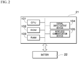
- FIG. 2 is a diagram showing the hardware configuration of the control device.
- control device 21 is a computer provided with hardware such as a CPU (Central Processing Unit) 101, a ROM (Read Only Memory) 102, a RAM (Random Access Memory) 103, a signal input/output device 104, and a wireless communication device 105.
- CPU Central Processing Unit
- ROM Read Only Memory
- RAM Random Access Memory
- the signal input/output device 104 inputs signals output from the shoe sole load sensor 18, the foot sole load sensor 19, the hip joint sensor 23, the knee joint sensor 24, the ankle joint sensor 25 and the acceleration sensor 26.
- the signal input/output device 104 outputs control signals for controlling the hip actuator 13, the knee actuator 14, and the ankle actuator 15.
- the control device 21 operates by power supplied from the battery 22.
- the wireless communication device 105 is communicatively connected with another device.
- FIG. 3 is a function block diagram of the control device.
- the control device 21 is activated based on the power supplied from the battery 22 by turning on the power button.
- the control device 21 executes the control program after startup.
- the control device 21 is provided with at least an information acquisition unit 211, an adaptive control unit 212, an actuator control unit 213, a power supply unit 214, and a storage unit 215.
- the information acquisition unit 211 acquires sensing information from the shoe sole load sensor 18, the foot sole load sensor 19, the hip joint sensor 23, the knee joint sensor 24, the ankle joint sensor 25 and the acceleration sensor 26.
- the sensing information of the shoe sole load sensor 18 and the foot sole load sensor 19 is load information indicating the detected load value.
- the sensing information of the hip joint sensor 23, the knee joint sensor 24, and the ankle joint sensor 25 is joint angle information indicating the detected joint angle.
- the sensing information of the acceleration sensor 26 is acceleration information that indicates the detected acceleration.
- the actuator control unit 213 controls the hip actuator 13, the knee actuator 14, and the ankle actuator 15.
- the power supply unit 214 supplies electric power from the battery 22 to each part of the control device 21.
- the adaptive control unit 212 is provided with a determination unit 2121 and a torque control unit 2122.
- the determination unit 2121 determines a repeated motion of the user on the basis of the acceleration detected by the acceleration sensor 26, the joint angle detected by the hip joint sensor 23, the knee joint sensor 24, and the ankle joint sensor 25, or the load value detected by the shoe sole load sensor 18 or the foot sole load sensor 19.
- the repeated motion is a gait cycle in which one period is from the start to the end of one step.
- the torque control unit 2122 compares a characteristic extracted on the basis of machine learning of repeated motions over a plurality of periods (hereinafter referred to as multiple periods) with a reference model of each motion. As a result, the torque control unit 2122 controls the output torque output by the hip actuator 13, the knee actuator 14, and the ankle actuator 15. Examples of a characteristic include the timing of heel strike, the timing of toe off, and the peak point of each joint torque.
- the heel strike is when the heel has landed.
- the toe off is when the toe has separated from the ground.
- the peak point of each joint torque is the peak time and the output value of the output torque output by the hip actuator 13, the knee actuator 14, and the ankle actuator 15, respectively.
- the storage unit 215 stores a reference model corresponding to each motion having different momentum such as walking and running.
- the reference model is a model for determining the control pattern of the output torque output by the hip actuator 13, the knee actuator 14, and the ankle actuator 15 based on the characteristics corresponding to each motion.
- the control pattern is determined by parameters used to calculate the output torque and the like.
- the parameters include, for example, control system parameters for determining the response of the hip actuator 13, the knee actuator 14, and the ankle actuator 15, and a threshold value for determining a stance or swing.
- the reference model corresponding to walking is data held in association with characteristics corresponding to walking with parameter setting values for walking and an algorithm for walking.
- the reference model corresponding to running is data held in association with the characteristics corresponding to running with the parameter setting values for running and an algorithm for running.
- the storage unit 215 may store a reference model corresponding to other motions other than walking and running.
- the reference model may be one according to the walking speed and the running speed. Further, the storage unit 215 stores an angle reference at each joint of each leg.
- control device 21 Next, the operation of the control device 21 according to the first embodiment will be described in detail.
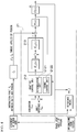
- FIG. 4 is an operation block diagram showing the operation of the control device according to the first embodiment.
- the adaptive control unit 212 controls the output torque output by the hip actuator 13, the knee actuator 14, and the ankle actuator 15 of each leg.
- the adaptive control unit 212 controls each output torque on the basis of the load values detected by the shoe sole load sensor 18 and the foot sole load sensor 19, the acceleration Acc detected by the acceleration sensor 26, each joint angle ⁇ k detected by each of the hip joint sensor 23, the knee joint sensor 24, and the ankle joint sensor 25, the angle reference ⁇ k0 , and the reference model stored by the storage unit 215.
- the determination unit 2121 determines the repeated motion of the user.
- a gait cycle is an example of a repeated motion.
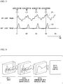
- FIG. 5 is a graph for explaining a method of determining the gait cycle.
- the horizontal axis of the graph shown in this figure indicates time.
- the vertical axis of the graph shown in this figure represents the magnitude of torque.
- the solid line 71 shown in the upper row shows an example of the transition of the hip joint torque.
- the hip joint torque is the output torque output by the hip actuator 13.
- the solid line 72 shown in the lower row shows an example of the transition of the knee joint torque.
- the knee joint torque is the output torque output by the knee actuator 14.
- the ankle actuator 15 outputs ankle joint torque. Similar to the hip joint torque and the knee joint torque, the value of the ankle joint torque also increases or decreases in a time period according to the walking motion of the user.
- acceleration ON indicates that the acceleration detected by the acceleration sensor 26 is equal to or greater than a predetermined threshold value.
- the acceleration is equal to or greater than a predetermined threshold value at times t1, t2, t3, t4, t5.
- the determination unit 2121 determines when the acceleration exceeds a predetermined threshold value, as the stance timing by one foot after the landing of one foot in the gait cycle from the start to the end of the walking step. Then, the determination unit 2121 determines one stance timing to the next stance timing of a foot to be one period of the gait cycle.
- the determination unit 2121 makes the duration from time t1, when the acceleration indicated by the acceleration sensor 26 has become equal to or greater than a predetermined threshold value indicating the start of the gait cycle, to time t2, when the acceleration has become equal to or greater than a predetermined threshold value, one period. Similarly, the determination unit 2121 sets the duration from time t2 to time t3 as the next period, sets the duration from time t3 to time t4 as the next period, and sets the duration from time t4 to time t5 as the next period.
- the determination unit 2121 outputs the gait cycle data for the latest N (N being an integer of 2 or more) periods to the torque control unit 2122. For example, the determination unit 2121 outputs the gait cycle data for several steps to the torque control unit 2122.
- the gait cycle data is transition data in the gait cycle for one period (step). The transition data shows the transition of each joint angle, the transition of each load value, and the transition of the output torque output by the hip actuator 13, the knee actuator 14, and the ankle actuator 15, in the gait cycle.
- the determination unit 2121 makes a determination of a repeated motion on the basis of the acceleration detected by the acceleration sensor 26, but the present invention is not thereto.
- the determination unit 2121 may determine a repeated motion based on the joint angles detected by the hip joint sensor 23, the knee joint sensor 24, and the ankle joint sensor 25.
- the torque control unit 2122 executes torque control processing on the basis of the gait cycle data (for N steps) over multiple periods.
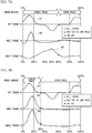
- FIG. 6 is a diagram showing an outline of torque control processing.
- the torque control unit 2122 inputs the gait cycle data of for each 1 step (Step ST1).
- the torque control unit 2122 performs machine learning such as convolution processing and weighting processing on the input gait cycle data using a characteristic extraction model based on a convolutional neural network, and extracts characteristics in the gait cycle (Step ST2).
- Examples of a characteristic include the timing of heel strike, the timing of toe off, and the peak point of joint torque.
- the torque control unit 2122 determines heel strike and toe off on the basis of the transition of the load value detected by the shoe sole load sensor 18 or the foot sole load sensor 19, or the transition of the joint angle detected by the hip joint sensor 23, the knee joint sensor 24, and the ankle joint sensor 25. For example, the torque control unit 2122 determines that the heel has landed when the load value exceeds the first threshold value. Further, the torque control unit 2122 determines that the toes have separated when the load value becomes equal to or less than the second threshold value. Further, the torque control unit 2122 determines the peak point of each joint torque on the basis of the transition of the output torque output by the hip actuator 13, the knee actuator 14, and the ankle actuator 15.
- FIGS. 7A and 7B are graphs showing an example of each characteristic in the gait cycle.
- the horizontal axis shows the percentage of time elapsed in one gait cycle.
- the upper row shows the transition of hip joint torque.
- the middle row shows the transition of knee joint torque.
- the lower row shows the transition of ankle torque.
- the symbol “o” indicates heel strike.
- the symbol “ ⁇ ” indicates the peak point of joint torque.
- the symbol “x” indicates toe off.
- FIG. 7A shows the transition of each joint torque during walking.
- the solid line 81 shown in the upper row shows the transition of hip joint torque.
- the solid line 82 shown in the middle row shows the transition of the knee joint torque.
- the solid line 83 shown in the lower row shows the transition of the ankle joint torque.
- the start time in the unit period of the gait cycle during walking is 0% of the elapsed period in the cycle, and the end time in the unit period of the gait cycle is 100% of the elapsed duration in the cycle.
- the duration from 0% to about 60% in the gait cycle during walking is the stance phase in which the leg is being a stance.
- the stance period is the period from heel strike to toe off.
- the duration from about 60% to 100% in the gait cycle during walking is the swing phase in which the leg is being a swing.
- the swing phase is the period from the toe off to the heel strike.
- the heel strike occurs at the 0% point.
- the toe off occurs at about the 60% point.
- the peaks of the hip joint torque and knee joint torque in the gait cycle during walking occur at points in the period from about 10% to about 20%.
- the peak of the ankle joint torque in the gait cycle during walking occurs at about the 50% point.
- FIG. 7B shows the transition of each joint torque during running.
- the solid line 91 shown in the upper row shows the transition of hip joint torque.
- the solid line 92 shown in the middle row shows the transition of knee joint torque.
- the solid line 93 shown in the lower row shows the transition of the ankle joint torque.
- the duration from 0% to about 35% in the gait cycle during running is the stance phase.
- the duration from about 35% to 100% in the gait cycle during running is the swing phase.
- the heel strike is at the 0% point in the gait cycle during running.
- the toe off is about the 35% point in the gait cycle during running.
- the peaks of the hip joint torque, knee joint torque, and ankle joint torque in the gait cycle during running occur at points in the period from about 10% to about 20%.
- the time ratio between the stance phase and the swing phase in the gait cycle differs between walking and running.
- the time ratio from the heel strike to the toe off is about 60% when walking, and about 40% when running with respect to the time of the entire gait cycle.
- the peak time of each joint in the gait cycle differs between walking and running.
- the torque control unit 2122 compares a reference model corresponding to each motion with the extracted characteristics, and determines the user's motion based on the difference (Step ST3 in FIG. 6 ). For example, the torque control unit 2122 determines that the reference model having the smallest difference between the characteristics of the reference model and the extracted characteristics to be the user's motion.
- the torque control unit 2122 controls the output torque with a control pattern according to the determined motion (Step ST4). That is, the control device 21 stores a plurality of reference models in advance, specifies the reference model having the smallest difference, and acquires control parameters of the control pattern corresponding to the reference model from the storage unit 215 or the like. Then, the torque control unit 2122 sets the optimum control parameters according to the difference between the determined motion and the reference model.
- the parameters are a control system parameters for determining the response of the hip actuator 13, the knee actuator 14, or the ankle actuator 15, a threshold value for making a determination of a stance or a swing, and the like.
- the torque control unit 2122 calculates the target values of the torque output by the hip actuator 13, the knee actuator 14, and the ankle actuator 15 on the basis of the control parameters and algorithms corresponding to the determined motion. Specifically, the torque control unit 2122 calculates the target value of each torque using the sensing information indicating the current value acquired from at least one of the shoe sole load sensor 18, the foot sole load sensor 19, the hip joint sensor 23, the knee joint sensor 24, the ankle joint sensor 25, or the acceleration sensor 26, and the angle reference of each joint. The torque control unit 2122 outputs the calculated target values of torque of the hip actuator 13, the knee actuator 14, and the ankle actuator 15 of each leg to the actuator control unit 213.
- the actuator control unit 213 controls the rotation angles of the hip actuator 13, the knee actuator 14, and the ankle actuator 15 with an angle controller K ci (s) on the basis of the target value of the torque. "s" indicates the frequency domain of the control system. Subsequently, the actuator control unit 213 causes the hip actuator 13, the knee actuator 14, and the ankle actuator 15 of each leg to output the torque ⁇ at the current timing by a force controller K bi (s).
- the interaction force F k between suits and person applied by the user, the applied torque l k applied by the user, and the output torque ⁇ in the kth of the time series (current value) become the dynamics P(s) of each actuator.
- the hip joint sensor 23, the knee joint sensor 24, and the ankle joint sensor 25 detect each joint angle ⁇ k in the kth of the time series in accordance with the dynamics G(s) of the powered suit 100 based on the dynamics P(s) of the hip actuator 13, the knee actuator 14, and the ankle actuator 15. Then, the control device 21 repeats the above-described processing.
- the actuator control unit 213 calculates the torque ⁇ using the following torque calculation formula as an example.
- “( ⁇ ) / G(s)” indicates a feedback factor to the actuator control unit 213.
- "F k ⁇ l k " indicates a feedforward factor.
- Ti indicates the target value of the torque calculated by the torque control unit.
- f( ⁇ ) indicates a function including an angle ⁇ based on the angle reference of the hip actuator 13, the knee actuator 14, and the ankle actuator 15.
- the torque calculation formula below is an example, and a formula other than the torque calculation formula shown below may be used.
- "s" indicates the frequency domain of the control system
- K bi indicates the control model of the force controller
- K ci indicates the control model of the angle controller.
- ⁇ K bi s T i ⁇ K ci s ⁇ f ⁇ / G s + F k ⁇ l k
- FIG. 8 is a flowchart showing the processing of the powered suit according to the first embodiment.
- the user wears the powered suit 100.
- the user inserts the foot sole load sensor 19 inside the foot harness 17.
- the foot sole load sensor 19 may be provided inside the foot harness 17 in advance.
- a size suitable for the size of the user's foot may be used.
- the user attaches the shoe sole load sensor 18 to the ground contact surface side of the foot harness 17 or the shoe sole plate 16 of the powered suit 100.
- the shoe sole load sensor 18 may also be provided in advance on the ground contact surface side of the foot harness 17 or the shoe sole plate 16.
- a size suitable for the foot harness 17 corresponding to the size of the user's foot may be used.
- the user operates the power button of the control device 21 provided in the powered suit 100 to turn on the power.
- the control device 21 is started.
- the user performs motions such as walking, running, leaping, and jumping while wearing the powered suit 100.
- the user may load luggage on the loading platform 20 of the powered suit 100 and perform motions such as walking, running, leaping, and jumping.
- the actuator control unit 213 of the control device 21 controls the hip actuator 13, the knee actuator 14, and the ankle actuator 15 so as to reduce the load on the user due to the weight of the luggage or the powered suit 100.
- the powered suit 100 unloads the weight of the luggage and the weight of the powered suit 100 on the user, and also assists walking.
- the information acquisition unit 211 acquires joint angle information from the hip joint sensor 23, the knee joint sensor 24, and the ankle joint sensor 25 at predetermined intervals (Step S101). Further, while the control device 21 is being driven, the information acquisition unit 211 acquires load information from the shoe sole load sensor 18 and the foot sole load sensor 19 at predetermined intervals (Step S102). In addition, while the control device 21 is being driven, the information acquisition unit 211 acquires acceleration information from the acceleration sensor 26 at a predetermined interval (Step S103).
- the predetermined interval is, for example, every short time such as every 10 milliseconds.
- the determination unit 2121 determines the gait cycle as a repeated motion based on the joint angle information, the load information, and the acceleration information acquired by the information acquisition unit 211 (Step S104), and generates gait cycle data.
- the torque control unit 2122 performs machine learning such as convolution processing and weighting processing on the gait cycle data of multiple periods using a characteristic extraction model based on a convolutional neural network, and extracts the characteristics (Step S105).
- the torque control unit 2122 compares the extracted characteristics with the characteristics of the reference model (Step S106). As described above, in the reference model, the characteristics thereof are associated with the parameters and the algorithm. The torque control unit 2122 specifies a reference model in which the difference between the extracted characteristics and the characteristics of the reference model is small, based on the result of the comparison. The torque control unit 2122 determines the motion based on the specified reference model and sets the parameters (Step S107). The torque control unit 2122 calculates the output value of the output torque using an algorithm corresponding to the determined motion (Step S108).
- the actuator control unit 213 causes the hip actuator 13, the knee actuator 14, and the ankle actuator 15 of each leg to output the torque of the calculated output value (Step S 109). After that, the process returns to the process of Step S101, and the control device 21 repeats the processes from steps S101 to S109 until the process is completed.
- the accurate required torque for each joint to support the load is calculated, so as to being capable of outputting by the hip actuator 13, the knee actuator 14, and the ankle actuator 15. For this reason, even if the user's motion pattern fluctuates significantly from low response to high response, such as a slow walking motion or an agile motion of running, the user's motion can always be tracked, and it is possible to realize assistance for reducing the load in a timely and appropriate manner for each motion.
- the torque control unit 2122 extracts a characteristic in the repeated motion and compares the characteristic with the reference model, the output torque can be controlled by the control pattern according to the user's motion. Therefore, since it is possible to control the output of the hip actuator 13, the knee actuator 14, and the ankle actuator 15 by adaptively predicting the user's motion, load reduction is possible for various motion patterns of the user. Further, the torque control unit 2122, using a characteristic extraction model based on a convolutional neural network, performs machine learning such as convolution processing and weighting processing, extracts a characteristic, and compares the characteristic with the reference model. Therefore, by clarifying the difference from the reference, it is possible to provide the optimum load reduction to each user.
- the real-time property may be impaired due to the delay in data transmission/reception, but in the present embodiment, the control device 21 included in the powered suit 100 performs the above process. For this reason, it is possible to respond to a sudden motion of the user without delay.
- the above-mentioned processing is executed on the basis of the sensing information detected by the shoe sole load sensor 18, the foot sole load sensor 19, the hip joint sensor 23, the knee joint sensor 24, the ankle joint sensor 25, and the acceleration sensor 26 included in the powered suit 100 attached to the lower limbs. For this reason, even when for example there is a discrepancy between the motions of the upper limbs and the lower limbs, it is possible to provide appropriate load reduction. Moreover, since the powered suit 100 has a relatively simple structure of being attached to the lower limbs, it can be easily attached and detached.
- the shoe sole load sensor 18 may be provided in advance on a side of the ground contact surface of the shoe sole plate 16 of the powered suit 100. Further, the foot sole load sensor 19 may be inserted in advance inside the foot harness 17.
- the shoe sole load sensor 18 has an area that covers the entire back surface of the foot harness 17, and the foot sole load sensor 19 has an area that covers the entire sole in the inner part of the foot harness 17.
- the shoe sole load sensor 18 may be capable of measuring the load applied to the ground contact surface from the shoe sole plate 16 or the foot harness 17 even when the position where the load is applied deviates.
- control device 21 is not limited thereto, and can be applied to general control of a multi-joint robot or the like (for example, a humanoid robot) having a non-linear mode transition.
- control device 21 is provided in the powered suit 100, but the present invention is not limited thereto, and another device that is communicatively connected with the powered suit 100 by wires or wirelessly may have the function of the control device 21.
- FIG. 9 is an operation block diagram showing the operation of the control device according to the second embodiment.
- the control device 21 further detects the external torque F received from the outside by each sensor, and further uses the external torque F to control the output torque output by the hip actuator 13, the knee actuator 14, and the ankle actuator 15.
- the external torque F is, for example, a torque value obtained by detecting the force received by the powered suit 100 from the outside by each sensor based on the landing impact, the dynamic acceleration, the deviation between the movement of the powered suit 100 and the user, and the like.
- each of the hip joint sensor 23, the knee joint sensor 24, and the ankle joint sensor 25 is provided with an external torque detection sensor 214 for detecting the external torque F. Then, the information acquisition unit 211 further acquires the external torque F from the external torque detection sensors 214 of each of the hip joint sensor 23, the knee joint sensor 24, and the ankle joint sensor 25.
- the external torque detection sensor 214 detects the value of the external torque F according to the amount of change by which the angle between the links rotatably attached, with reference to the joint to which each joint sensor is attached, has changed due to an external force.
- the amount of change may be the difference between the angle instructed by the actuator control unit 213 and the angle when the change is momentarily caused by a force obtained from the outside.
- the external torque detection sensor 214 may calculate the amount of change by which the angle between the links rotatably attached based on the joint has momentarily changed due to an external force, from the difference in the distance at any position on those links rather than the difference between the angles.
- FIG. 10 is a second flowchart showing the processing of the powered suit according to the second embodiment.
- the information acquisition unit 211 acquires joint angle information from the hip joint sensor 23, the knee joint sensor 24, and the ankle joint sensor 25 at predetermined intervals (Step S201), and acquires the external torque F from the external torque detection sensor 214 of each sensor (Step S202). While the control device 21 is being driven, the information acquisition unit 211 acquires load information from the shoe sole load sensor 18 and the foot sole load sensor 19 at predetermined intervals (Step S203). While the control device 21 is being driven, the information acquisition unit 211 acquires acceleration information from the acceleration sensor 26 at a predetermined interval (Step S204). The predetermined interval is, for example, every short time such as every 10 milliseconds.
- the determination unit 2121 determines the gait cycle as a repeated motion based on the joint angle information, the external torque F, the load information, and the acceleration information acquired by the information acquisition unit 211 (Step S205), and generates gait cycle data.
- the torque control unit 2122 performs machine learning such as convolution processing and weighting processing on the gait cycle data of multiple cycles using a characteristic extraction model based on a convolutional neural network, and extracts the characteristics (Step S206).
- the torque control unit 2122 compares the extracted characteristics with the characteristics of the reference model (Step S207).
- the torque control unit 2122 specifies a reference model in which the difference between the extracted characteristics and the characteristics of the reference model is small, based on the result of comparison.
- the torque control unit 2122 determines the motion based on the specified reference model and sets parameters (Step S208).
- the torque control unit 2122 calculates the output value of the output torque using an algorithm corresponding to the determined motion (Step S209).
- the torque control unit 2122 calculates the output value of the output torque that cancels the acquired external torque F in the calculation of the output value of the output torque.
- the output value of the output torque calculated by the torque control unit 2122 becomes a value that tracks the actual torque including the dynamic element.
- the actuator control unit 213 outputs the torque of the output value calculated from the hip actuator 13, the knee actuator 14, and the ankle actuator 15 of each leg (Step S210). After that, the process returns to the process of Step S201, and the control device 21 repeats the processes from steps S201 to S210 until the process is completed.
- the above-mentioned processing of the torque control unit is an example of a mode of calculating the output value of the torque of the drive mechanism of each sensor or the like that cancels the external torque F and controlling the drive mechanism based on the output value.
- the torque control unit 2122 calculates the deviation between the characteristics of the gait cycle calculated by machine learning and the characteristics of the reference model.
- the torque control unit 2122 in Step S207 determines the motion and sets the parameters based on the relationship between the torque and the time indicated by the reference model.
- the torque control unit 2122 performs the following processing. That is, the torque control unit 2122 calculates the reference model after a period change, in which the period indicated by the relationship between the torque and the time of the gait cycle indicated by the reference model is shifted so that the timing of the characteristics of the reference model matches the characteristics of the gait cycle calculated by machine learning. Then, in Step S207, the torque control unit 2122 determines the motion and sets the parameters based on the relationship between the torque and the time indicated by the reference model after the period change. Thereby, the timing of the stance phase and the swing phase indicated by the reference model can be matched with the stance phase and the swing phase of the user's gait.
- the processing of this torque control unit is one aspect of a process that, based on the deviation between the characteristics extracted on the basis of machine learning of a repeated motion and the characteristics of the reference model, corrects the period indicated by the relationship between the torque and time in the reference model so that the deviation is reduced, and specifies the timing of the repeated motion based on the reference model.
- the timing of the stance phase and the swing phase indicated by the reference model can be matched with the stance phase and the swing phase of the user's walk, it is possible to determine the period of the walking without detecting the start of the walking step on the basis of whether or not the acceleration exceeds a predetermined threshold value. That is, in this case, the acceleration sensor 26 becomes unnecessary.
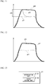
- FIG. 11 is a graph showing the relationship between the output of the torque control unit 2122 and the target torque when the control according to the second embodiment is not performed.
- FIG. 12 is a graph showing the relationship between the output of the torque control unit 2122 and the target torque when the control according to the second embodiment is performed.
- the torque control unit 2122 calculates an output value that matches the torque according to the time transition indicated by the target torque p1 based on a static element.
- the torque control unit 2122 calculates an output value that matches the torque according to the time transition indicated by the target torque p2 based on the dynamic element.
- the output p3 of the torque control unit 2122 will be described when the torque control unit 2122 matches the torque corresponding to the time transition indicated by the target torque p1 based on the static element.
- the output p3 of the torque control unit 2122 is the torque generated at each joint due to the influence of the external torque F, that torque transitions so as to approach the target torque p1 under the control of the torque control unit 2122 (p3).
- the torque value corresponding to the time indicated by the output value p3 imposes a burden of the torque difference indicated as the value pa on the user at the initial stage when the output value p3 does not match the target torque p1 ( FIG. 11 ).
- the torque control unit 2122 calculates the output value p3 so as to match the target torque p2 ( FIG. 12 ), so that the burden on the user can be reduced.
- FIG. 13 is a diagram showing the minimum configuration of the control device.
- the control device 21 as one aspect of the load reduction device may have at least the functions of the determination unit 2121 and the torque control unit 2122 described above.
- the determination unit 2121 determines repeated motions by a user.
- the torque control unit 2122 extracts characteristics in repeated motions by the convolution process and compares them with the reference model of each motion. As a result, the torque control unit 2122 controls the torque output by the hip actuator 13, the knee actuator 14, and the ankle actuator 15 in order to reduce the load exerted to the user at the joints of the user's legs.
- the above-mentioned control device may also be a computer provided with hardware such as the CPU (Central Processing Unit) 101, the ROM (Read Only Memory) 102, the RAM (Random Access Memory) 103, an HDD (Hard Disk Drive) 104, and the wireless communication device 105.
- the CPU Central Processing Unit
- the ROM Read Only Memory
- the RAM Random Access Memory
- HDD Hard Disk Drive
- the control device described above has a computer system inside.
- the process of each processing described above is stored in a computer-readable recording medium in the form of a program, with the process being performed by the computer reading and executing this program.
- the computer-readable recording medium refers to a magnetic disk, a magneto-optical disk, a CD-ROM, a DVD-ROM, a semiconductor memory, or the like.
- this computer program may be distributed to a computer via a communication line, and the computer receiving the distribution may execute the program.
- the above-mentioned program may be for realizing some of the functions described above.
- the above-mentioned program may be a so-called differential file (differential program) that can realize the above-mentioned functions in combination with a program already recorded in the computer system.
Landscapes
- Engineering & Computer Science (AREA)
- Robotics (AREA)
- Mechanical Engineering (AREA)
- Health & Medical Sciences (AREA)
- Animal Behavior & Ethology (AREA)
- Life Sciences & Earth Sciences (AREA)
- Veterinary Medicine (AREA)
- Epidemiology (AREA)
- Pain & Pain Management (AREA)
- Physical Education & Sports Medicine (AREA)
- Rehabilitation Therapy (AREA)
- Public Health (AREA)
- General Health & Medical Sciences (AREA)
- Physics & Mathematics (AREA)
- Automation & Control Theory (AREA)
- General Physics & Mathematics (AREA)
- Rehabilitation Tools (AREA)
- Manipulator (AREA)
Abstract
Description
- The present invention relates to a load reduction device, a load reduction method, and a storage medium storing a program.
- There is known a load reduction device that performs assistance of a load such as a walking motion of a user and mitigates the load of luggage carried by the user, when worn by the user. The load reduction device is sometimes called a powered suit when wearable by a person.
- Patent Document 1 discloses a technique of identifying at least one predefined gait event using the output of at least one sensor, adjusting the actuation profile of at least one actuator, and the actuation profile of the at least one actuator generating a beneficial moment about at least one joint.
- Patent Document 2 discloses a technique of sensing the motion of at least one joint or measuring the motion of at least one joint, determining the motion state of at least one joint based on the sensed or measured motion of the at least one joint, and controlling a walking assist robot on the basis of the determination result regarding the operating state of the at least one joint.
- Patent Document 3 discloses a technique of acquiring a state signal indicating the movement of the upper limbs of the user and determining an auxiliary timing which is a timing of assisting the user's action from a change in the state signal.
- Patent Document 4 discloses a technique for determining the drive amount of an actuator according to a sensor value when a pedestrian walks according to a walking algorithm for determining the drive amount of the actuator that drives the joint of the walking support device. Patent Document 4 discloses that this walking algorithm is information generated by statistically processing walking data showing the characteristics of walking.
-
- [Patent Document 1] Published
Japanese Translation No. 2016-539723 of the PCT International Publication - [Patent Document 2]
Japanese Unexamined Patent Application Publication No. 2015-089510 - [Patent Document 3]
Japanese Unexamined Patent Application Publication No. 2015-177863 - [Patent Document 4]
WO 2016/038824 - While the torque that is output by the load reduction device required for load reduction varies sequentially according to the momentum of the user's motion, it is desired to perform more appropriate load reduction for the user's motion.
- Therefore, an example object of the present invention is to provide a load reduction device, a load reduction method, and a storage medium for storing a program therein that can solve the above-mentioned problems.
- According to a first aspect of the present invention, a load reduction device includes a determination unit configured to determine a repeated motion that is repeated by a user; and a torque control unit configured to control, by comparing a characteristic extracted on the basis of machine learning for repeated motions and a reference model, torque output by a drive mechanism to reduce a load on the user at a joint of a leg of the user.
- According to a second aspect of the present invention, a load reduction method includes determining a repeated motion that is repeated by a user; and controlling, by comparing a characteristic extracted on the basis of machine learning for repeated motions and a reference model, torque output by a drive mechanism to reduce a load on the user at a joint of a leg of the user.
- According to a third aspect of the present invention, a program stored in a storage medium causes a computer of a load reduction device to execute processes, the processes includes: determining a repeated motion that is repeated by a user; and controlling, by comparing a characteristic extracted on the basis of machine learning for repeated motions and a reference model, torque output by a drive mechanism to reduce a load on the user at a joint of a leg of the user.
- According to the present invention, it is possible to provide a load reduction device capable of more appropriate load reduction for the user's motions.
-
-
FIG. 1 is a perspective view showing a configuration of a powered suit according to an embodiment of the present invention. -
FIG. 2 is a diagram showing a hardware configuration of a control device according to an embodiment of the present invention. -
FIG. 3 is a function block diagram of a control device according to an embodiment of the present invention. -
FIG. 4 is an operation block diagram showing the operation of the control device according to the first embodiment. -
FIG. 5 is a graph for explaining a method for determining a gait cycle according to an embodiment of the present invention. -
FIG. 6 is a diagram showing an outline of torque control processing according to an embodiment of the present invention. -
FIG. 7A is a graph showing an example of each characteristic in the gait cycle according to the embodiment of the present invention. -
FIG. 7B is a graph showing an example of each characteristic in the gait cycle according to the embodiment of the present invention. -
FIG. 8 is a flowchart showing processing of a powered suit according to the first embodiment. -
FIG. 9 is an operation block diagram showing the operation of the control device according to the second embodiment. -
FIG. 10 is a flowchart showing processing of a powered suit according to the second embodiment. -
FIG. 11 is a graph showing the relationship between the output of the torque control unit and the target torque when the control according to the second embodiment is not performed. -
FIG. 12 is a graph showing the relationship between the output of the torque control unit and the target torque when the control according to the second embodiment is performed. -
FIG. 13 is a diagram showing a minimum configuration of a control device according to an embodiment of the present invention. - Hereinbelow, a load reduction device according to an embodiment of the present invention, a load reduction method, and a storage medium for storing a program therein will be described with reference to the drawings.
-
FIG. 1 is a perspective view showing a configuration of a powered suit according to the present embodiment. - A powered
suit 100 is one aspect of the load reduction device. The poweredsuit 100 is constituted by askeleton portion 11, abelt 12, ahip actuator 13, aknee actuator 14, anankle actuator 15, ashoe sole plate 16, afoot harness 17, a shoesole load sensor 18, a footsole load sensor 19, aloading platform 20, acontrol device 21, abattery 22, ahip joint sensor 23, aknee joint sensor 24, anankle joint sensor 25, anacceleration sensor 26, and the like. Theskeleton portion 11 is roughly classified into afirst skeleton portion 111, asecond skeleton portion 112, and athird skeleton portion 113 as an example. - As shown in
FIG. 1 , the poweredsuit 100 is configured as follows so as to support theloading platform 20, which is one aspect of the mechanism for holding luggage as an example. That is, the poweredsuit 100 is provided with thefirst skeleton portion 111, and the left andright hip actuators 13 are coupled rotatable to thefirst skeleton portion 111 and thesecond skeleton portion 112, which corresponds to the left or right thigh portion of the user wearing the poweredsuit 100, respectively. The left andright knee actuators 14 couple rotatable the correspondingsecond skeleton portion 112 on the left or right side and the correspondingthird skeleton portion 113 along the left or right lower leg portion of the user wearing the poweredsuit 100. Theankle actuators 15 couple rotatable to the correspondingthird skeleton portion 113, and the left or right side to a correspondingshoe sole plate 16 provided on the back of thefoot harness 17 on the left or right side of the user wearing the poweredsuit 100. Theactuators - The user who wears the powered
suit 100 attaches his/her left and right feet to thecorresponding foot harnesses 17, and fixes thefirst skeleton portion 111 to the waist with thebelt 12 so that thefirst skeleton portion 111 is closely attached to the waist. The poweredsuit 100 has a structure in which most of the load of the luggage and the load of the poweredsuit 100 is released to the ground surface in contact with the soles of the feet via theskeleton portion 11 and thehip actuator 13, theknee actuator 14, and theankle actuator 15. The user turns on thecontrol device 21 of the poweredsuit 100. Thecontrol device 21 controls thehip actuator 13, theknee actuator 14, and theankle actuator 15 so as to transmit as much of the device weight as possible, which is the sum of the load of the luggage loaded on theloading platform 20 and the weight of the poweredsuit 100, to the walking surface via theskeleton portion 11 and thehip actuator 13, theknee actuator 14, and theankle actuator 15. Thereby, the poweredsuit 100 mitigates the burden such as the load of the luggage on the user who wears the poweredsuit 100, loads the luggage on theloading platform 20, and walks. - The
hip joint sensor 23 is installed in thehip actuator 13, and detects the hip joint angle, that is, the angle formed between thefirst skeleton portion 111 and thesecond skeleton portion 112, by an encoder. Theknee joint sensor 24 is installed in theknee actuator 14, and detects the knee joint angle, that is, the angle between thesecond skeleton portion 112 and thethird skeleton portion 113, by the encoder. Theankle joint sensor 25 is installed in theankle actuator 15, and detects the ankle joint angle, that is, the angle between thethird skeleton portion 113 and theshoe sole plate 16, by the encoder. Thehip joint sensor 23, theknee joint sensor 24, and theankle joint sensor 25 detect the angle of each joint of each leg of the user (hereinafter referred to as the "joint angle"). Theacceleration sensor 26 detects the acceleration of the user's lower limbs. - The shoe
sole load sensor 18 is provided on the bottom of thefoot harness 17 corresponding to the shoe worn by the user. Further, the shoesole load sensor 18 is provided on the ground contact surface side of theshoe sole plate 16 that transmits the weight of the poweredsuit 100 and luggage to the ground contact surface, and thefoot harness 17 that transmits the user's weight to the ground contact surface so as to cover the entire back surface of theshoe sole plate 16 and thefoot harness 17. The footsole load sensor 19 is provided in thefoot harness 17 so as to cover the entire sole surface so that the weight thereof can be measured from the sole of the user. For example, the footsole load sensor 19 may be provided between the insole of thefoot harness 17 and the shoesole plate 16, or may be provided on the upper portion of the shoesole plate 16. - As an example, the shoe
sole load sensor 18 and the footsole load sensor 19 are sensors in which electrodes are arranged in a matrix on the front and back of a thin sheet-like insulator. The shoesole load sensor 18 and the footsole load sensor 19 measure the electrical resistance of the lattice points of the electrodes, and output the measured values to thecontrol device 21. Thecontrol device 21 calculates the pressure applied to each lattice point and the load on the entire surface of the sensor sheet based on the electrical resistance value of each lattice point. -
FIG. 2 is a diagram showing the hardware configuration of the control device. - As shown in this figure, the
control device 21 is a computer provided with hardware such as a CPU (Central Processing Unit) 101, a ROM (Read Only Memory) 102, a RAM (Random Access Memory) 103, a signal input/output device 104, and awireless communication device 105. - The signal input/
output device 104 inputs signals output from the shoesole load sensor 18, the footsole load sensor 19, the hipjoint sensor 23, the kneejoint sensor 24, the anklejoint sensor 25 and theacceleration sensor 26. The signal input/output device 104 outputs control signals for controlling thehip actuator 13, theknee actuator 14, and theankle actuator 15. Thecontrol device 21 operates by power supplied from thebattery 22. - The
wireless communication device 105 is communicatively connected with another device. -
FIG. 3 is a function block diagram of the control device. - The
control device 21 is activated based on the power supplied from thebattery 22 by turning on the power button. Thecontrol device 21 executes the control program after startup. As a result, thecontrol device 21 is provided with at least aninformation acquisition unit 211, anadaptive control unit 212, anactuator control unit 213, apower supply unit 214, and astorage unit 215. - The
information acquisition unit 211 acquires sensing information from the shoesole load sensor 18, the footsole load sensor 19, the hipjoint sensor 23, the kneejoint sensor 24, the anklejoint sensor 25 and theacceleration sensor 26. The sensing information of the shoesole load sensor 18 and the footsole load sensor 19 is load information indicating the detected load value. The sensing information of the hipjoint sensor 23, the kneejoint sensor 24, and the anklejoint sensor 25 is joint angle information indicating the detected joint angle. The sensing information of theacceleration sensor 26 is acceleration information that indicates the detected acceleration. - The
actuator control unit 213 controls thehip actuator 13, theknee actuator 14, and theankle actuator 15. - When the power button is turned on, the
power supply unit 214 supplies electric power from thebattery 22 to each part of thecontrol device 21. - The
adaptive control unit 212 is provided with adetermination unit 2121 and atorque control unit 2122. - The
determination unit 2121 determines a repeated motion of the user on the basis of the acceleration detected by theacceleration sensor 26, the joint angle detected by the hipjoint sensor 23, the kneejoint sensor 24, and the anklejoint sensor 25, or the load value detected by the shoesole load sensor 18 or the footsole load sensor 19. For example, the repeated motion is a gait cycle in which one period is from the start to the end of one step. - The
torque control unit 2122 compares a characteristic extracted on the basis of machine learning of repeated motions over a plurality of periods (hereinafter referred to as multiple periods) with a reference model of each motion. As a result, thetorque control unit 2122 controls the output torque output by thehip actuator 13, theknee actuator 14, and theankle actuator 15. Examples of a characteristic include the timing of heel strike, the timing of toe off, and the peak point of each joint torque. The heel strike is when the heel has landed. The toe off is when the toe has separated from the ground. The peak point of each joint torque is the peak time and the output value of the output torque output by thehip actuator 13, theknee actuator 14, and theankle actuator 15, respectively. - The
storage unit 215 stores a reference model corresponding to each motion having different momentum such as walking and running. The reference model is a model for determining the control pattern of the output torque output by thehip actuator 13, theknee actuator 14, and theankle actuator 15 based on the characteristics corresponding to each motion. The control pattern is determined by parameters used to calculate the output torque and the like. The parameters include, for example, control system parameters for determining the response of thehip actuator 13, theknee actuator 14, and theankle actuator 15, and a threshold value for determining a stance or swing. - For example, the reference model corresponding to walking is data held in association with characteristics corresponding to walking with parameter setting values for walking and an algorithm for walking. Further, the reference model corresponding to running is data held in association with the characteristics corresponding to running with the parameter setting values for running and an algorithm for running.
- Note that the
storage unit 215 may store a reference model corresponding to other motions other than walking and running. The reference model may be one according to the walking speed and the running speed. Further, thestorage unit 215 stores an angle reference at each joint of each leg. - Next, the operation of the
control device 21 according to the first embodiment will be described in detail. -
FIG. 4 is an operation block diagram showing the operation of the control device according to the first embodiment. - First, the
adaptive control unit 212 controls the output torque output by thehip actuator 13, theknee actuator 14, and theankle actuator 15 of each leg. Theadaptive control unit 212 controls each output torque on the basis of the load values detected by the shoesole load sensor 18 and the footsole load sensor 19, the acceleration Acc detected by theacceleration sensor 26, each joint angle θk detected by each of the hipjoint sensor 23, the kneejoint sensor 24, and the anklejoint sensor 25, the angle reference θk0, and the reference model stored by thestorage unit 215. - More specifically, first, the
determination unit 2121 determines the repeated motion of the user. A gait cycle is an example of a repeated motion. -
FIG. 5 is a graph for explaining a method of determining the gait cycle. - The horizontal axis of the graph shown in this figure indicates time. The vertical axis of the graph shown in this figure represents the magnitude of torque. The
solid line 71 shown in the upper row shows an example of the transition of the hip joint torque. The hip joint torque is the output torque output by thehip actuator 13. Thesolid line 72 shown in the lower row shows an example of the transition of the knee joint torque. The knee joint torque is the output torque output by theknee actuator 14. In addition, theankle actuator 15 outputs ankle joint torque. Similar to the hip joint torque and the knee joint torque, the value of the ankle joint torque also increases or decreases in a time period according to the walking motion of the user. - Further, "Acceleration ON" indicates that the acceleration detected by the
acceleration sensor 26 is equal to or greater than a predetermined threshold value. In the illustrated example, the acceleration is equal to or greater than a predetermined threshold value at times t1, t2, t3, t4, t5. - The
determination unit 2121 determines when the acceleration exceeds a predetermined threshold value, as the stance timing by one foot after the landing of one foot in the gait cycle from the start to the end of the walking step. Then, thedetermination unit 2121 determines one stance timing to the next stance timing of a foot to be one period of the gait cycle. - In the example shown in
FIG. 5 , thedetermination unit 2121 makes the duration from time t1, when the acceleration indicated by theacceleration sensor 26 has become equal to or greater than a predetermined threshold value indicating the start of the gait cycle, to time t2, when the acceleration has become equal to or greater than a predetermined threshold value, one period. Similarly, thedetermination unit 2121 sets the duration from time t2 to time t3 as the next period, sets the duration from time t3 to time t4 as the next period, and sets the duration from time t4 to time t5 as the next period. - The
determination unit 2121 outputs the gait cycle data for the latest N (N being an integer of 2 or more) periods to thetorque control unit 2122. For example, thedetermination unit 2121 outputs the gait cycle data for several steps to thetorque control unit 2122. The gait cycle data is transition data in the gait cycle for one period (step). The transition data shows the transition of each joint angle, the transition of each load value, and the transition of the output torque output by thehip actuator 13, theknee actuator 14, and theankle actuator 15, in the gait cycle. - In this example, the
determination unit 2121 makes a determination of a repeated motion on the basis of the acceleration detected by theacceleration sensor 26, but the present invention is not thereto. Thedetermination unit 2121 may determine a repeated motion based on the joint angles detected by the hipjoint sensor 23, the kneejoint sensor 24, and the anklejoint sensor 25. Thetorque control unit 2122 executes torque control processing on the basis of the gait cycle data (for N steps) over multiple periods. -
FIG. 6 is a diagram showing an outline of torque control processing. - The
torque control unit 2122 inputs the gait cycle data of for each 1 step (Step ST1). Thetorque control unit 2122 performs machine learning such as convolution processing and weighting processing on the input gait cycle data using a characteristic extraction model based on a convolutional neural network, and extracts characteristics in the gait cycle (Step ST2). - Examples of a characteristic include the timing of heel strike, the timing of toe off, and the peak point of joint torque. The
torque control unit 2122 determines heel strike and toe off on the basis of the transition of the load value detected by the shoesole load sensor 18 or the footsole load sensor 19, or the transition of the joint angle detected by the hipjoint sensor 23, the kneejoint sensor 24, and the anklejoint sensor 25. For example, thetorque control unit 2122 determines that the heel has landed when the load value exceeds the first threshold value. Further, thetorque control unit 2122 determines that the toes have separated when the load value becomes equal to or less than the second threshold value. Further, thetorque control unit 2122 determines the peak point of each joint torque on the basis of the transition of the output torque output by thehip actuator 13, theknee actuator 14, and theankle actuator 15. -
FIGS. 7A and 7B are graphs showing an example of each characteristic in the gait cycle. - In each graph shown in
FIGS. 7A and 7B , the horizontal axis shows the percentage of time elapsed in one gait cycle. The upper row shows the transition of hip joint torque. The middle row shows the transition of knee joint torque. The lower row shows the transition of ankle torque. The symbol "o" indicates heel strike. The symbol "Δ" indicates the peak point of joint torque. The symbol "x" indicates toe off. -
FIG. 7A shows the transition of each joint torque during walking. - The
solid line 81 shown in the upper row shows the transition of hip joint torque. Thesolid line 82 shown in the middle row shows the transition of the knee joint torque. Thesolid line 83 shown in the lower row shows the transition of the ankle joint torque. The start time in the unit period of the gait cycle during walking is 0% of the elapsed period in the cycle, and the end time in the unit period of the gait cycle is 100% of the elapsed duration in the cycle. - Then, the duration from 0% to about 60% in the gait cycle during walking is the stance phase in which the leg is being a stance. The stance period is the period from heel strike to toe off. In addition, the duration from about 60% to 100% in the gait cycle during walking is the swing phase in which the leg is being a swing. In the gait cycle during walking, the swing phase is the period from the toe off to the heel strike.
- Also, in the gait cycle during walking, the heel strike occurs at the 0% point. In addition, in the gait cycle during walking, the toe off occurs at about the 60% point. In addition, the peaks of the hip joint torque and knee joint torque in the gait cycle during walking occur at points in the period from about 10% to about 20%. The peak of the ankle joint torque in the gait cycle during walking occurs at about the 50% point.
-
FIG. 7B shows the transition of each joint torque during running. - The
solid line 91 shown in the upper row shows the transition of hip joint torque. Thesolid line 92 shown in the middle row shows the transition of knee joint torque. Thesolid line 93 shown in the lower row shows the transition of the ankle joint torque. The duration from 0% to about 35% in the gait cycle during running is the stance phase. The duration from about 35% to 100% in the gait cycle during running is the swing phase. The heel strike is at the 0% point in the gait cycle during running. The toe off is about the 35% point in the gait cycle during running. In addition, the peaks of the hip joint torque, knee joint torque, and ankle joint torque in the gait cycle during running occur at points in the period from about 10% to about 20%. - As shown in
FIGS. 7A and 7B , the time ratio between the stance phase and the swing phase in the gait cycle differs between walking and running. For example, the time ratio from the heel strike to the toe off is about 60% when walking, and about 40% when running with respect to the time of the entire gait cycle. In addition, the peak time of each joint in the gait cycle differs between walking and running. - Therefore, the
torque control unit 2122 compares a reference model corresponding to each motion with the extracted characteristics, and determines the user's motion based on the difference (Step ST3 inFIG. 6 ). For example, thetorque control unit 2122 determines that the reference model having the smallest difference between the characteristics of the reference model and the extracted characteristics to be the user's motion. - Then, the
torque control unit 2122 controls the output torque with a control pattern according to the determined motion (Step ST4). That is, thecontrol device 21 stores a plurality of reference models in advance, specifies the reference model having the smallest difference, and acquires control parameters of the control pattern corresponding to the reference model from thestorage unit 215 or the like. Then, thetorque control unit 2122 sets the optimum control parameters according to the difference between the determined motion and the reference model. As described above, the parameters are a control system parameters for determining the response of thehip actuator 13, theknee actuator 14, or theankle actuator 15, a threshold value for making a determination of a stance or a swing, and the like. - Then, the
torque control unit 2122 calculates the target values of the torque output by thehip actuator 13, theknee actuator 14, and theankle actuator 15 on the basis of the control parameters and algorithms corresponding to the determined motion. Specifically, thetorque control unit 2122 calculates the target value of each torque using the sensing information indicating the current value acquired from at least one of the shoesole load sensor 18, the footsole load sensor 19, the hipjoint sensor 23, the kneejoint sensor 24, the anklejoint sensor 25, or theacceleration sensor 26, and the angle reference of each joint. Thetorque control unit 2122 outputs the calculated target values of torque of thehip actuator 13, theknee actuator 14, and theankle actuator 15 of each leg to theactuator control unit 213. - The
actuator control unit 213 controls the rotation angles of thehip actuator 13, theknee actuator 14, and theankle actuator 15 with an angle controller Kci(s) on the basis of the target value of the torque. "s" indicates the frequency domain of the control system. Subsequently, theactuator control unit 213 causes thehip actuator 13, theknee actuator 14, and theankle actuator 15 of each leg to output the torque τ at the current timing by a force controller Kbi(s). - Thereby, the interaction force Fk between suits and person applied by the user, the applied torque lk applied by the user, and the output torque τ in the kth of the time series (current value) become the dynamics P(s) of each actuator. The hip
joint sensor 23, the kneejoint sensor 24, and the anklejoint sensor 25 detect each joint angle θk in the kth of the time series in accordance with the dynamics G(s) of thepowered suit 100 based on the dynamics P(s) of thehip actuator 13, theknee actuator 14, and theankle actuator 15. Then, thecontrol device 21 repeats the above-described processing. - Note that the
actuator control unit 213 calculates the torque τ using the following torque calculation formula as an example. In this torque calculation formula (1), "(θ) / G(s)" indicates a feedback factor to theactuator control unit 213. "Fk·lk" indicates a feedforward factor. Ti indicates the target value of the torque calculated by the torque control unit. f(θ) indicates a function including an angle θ based on the angle reference of thehip actuator 13, theknee actuator 14, and theankle actuator 15. The torque calculation formula below is an example, and a formula other than the torque calculation formula shown below may be used. In the torque calculation formula (1), "s" indicates the frequency domain of the control system, Kbi indicates the control model of the force controller, and Kci indicates the control model of the angle controller.
-
FIG. 8 is a flowchart showing the processing of the powered suit according to the first embodiment. - First, the user wears the
powered suit 100. At this time, the user inserts the footsole load sensor 19 inside thefoot harness 17. The footsole load sensor 19 may be provided inside thefoot harness 17 in advance. As the area of the footsole load sensor 19, a size suitable for the size of the user's foot may be used. Further, the user attaches the shoesole load sensor 18 to the ground contact surface side of thefoot harness 17 or the shoesole plate 16 of thepowered suit 100. The shoesole load sensor 18 may also be provided in advance on the ground contact surface side of thefoot harness 17 or the shoesole plate 16. As the area of the shoesole load sensor 18, a size suitable for thefoot harness 17 corresponding to the size of the user's foot may be used. - The user operates the power button of the
control device 21 provided in thepowered suit 100 to turn on the power. As a result, thecontrol device 21 is started. The user performs motions such as walking, running, leaping, and jumping while wearing thepowered suit 100. The user may load luggage on theloading platform 20 of thepowered suit 100 and perform motions such as walking, running, leaping, and jumping. Theactuator control unit 213 of thecontrol device 21 controls thehip actuator 13, theknee actuator 14, and theankle actuator 15 so as to reduce the load on the user due to the weight of the luggage or thepowered suit 100. As a result, thepowered suit 100 unloads the weight of the luggage and the weight of thepowered suit 100 on the user, and also assists walking. - While the
control device 21 is being driven, theinformation acquisition unit 211 acquires joint angle information from the hipjoint sensor 23, the kneejoint sensor 24, and the anklejoint sensor 25 at predetermined intervals (Step S101). Further, while thecontrol device 21 is being driven, theinformation acquisition unit 211 acquires load information from the shoesole load sensor 18 and the footsole load sensor 19 at predetermined intervals (Step S102). In addition, while thecontrol device 21 is being driven, theinformation acquisition unit 211 acquires acceleration information from theacceleration sensor 26 at a predetermined interval (Step S103). The predetermined interval is, for example, every short time such as every 10 milliseconds. - The
determination unit 2121 determines the gait cycle as a repeated motion based on the joint angle information, the load information, and the acceleration information acquired by the information acquisition unit 211 (Step S104), and generates gait cycle data. Thetorque control unit 2122 performs machine learning such as convolution processing and weighting processing on the gait cycle data of multiple periods using a characteristic extraction model based on a convolutional neural network, and extracts the characteristics (Step S105). - The
torque control unit 2122 compares the extracted characteristics with the characteristics of the reference model (Step S106). As described above, in the reference model, the characteristics thereof are associated with the parameters and the algorithm. Thetorque control unit 2122 specifies a reference model in which the difference between the extracted characteristics and the characteristics of the reference model is small, based on the result of the comparison. Thetorque control unit 2122 determines the motion based on the specified reference model and sets the parameters (Step S107). Thetorque control unit 2122 calculates the output value of the output torque using an algorithm corresponding to the determined motion (Step S108). - The
actuator control unit 213 causes thehip actuator 13, theknee actuator 14, and theankle actuator 15 of each leg to output the torque of the calculated output value (Step S 109). After that, the process returns to the process of Step S101, and thecontrol device 21 repeats the processes from steps S101 to S109 until the process is completed. - According to the above processing, the accurate required torque for each joint to support the load is calculated, so as to being capable of outputting by the
hip actuator 13, theknee actuator 14, and theankle actuator 15. For this reason, even if the user's motion pattern fluctuates significantly from low response to high response, such as a slow walking motion or an agile motion of running, the user's motion can always be tracked, and it is possible to realize assistance for reducing the load in a timely and appropriate manner for each motion. - For example, since the
torque control unit 2122 extracts a characteristic in the repeated motion and compares the characteristic with the reference model, the output torque can be controlled by the control pattern according to the user's motion. Therefore, since it is possible to control the output of thehip actuator 13, theknee actuator 14, and theankle actuator 15 by adaptively predicting the user's motion, load reduction is possible for various motion patterns of the user. Further, thetorque control unit 2122, using a characteristic extraction model based on a convolutional neural network, performs machine learning such as convolution processing and weighting processing, extracts a characteristic, and compares the characteristic with the reference model. Therefore, by clarifying the difference from the reference, it is possible to provide the optimum load reduction to each user. - Further, when a different device from the
powered suit 100 performs the above processing, the real-time property may be impaired due to the delay in data transmission/reception, but in the present embodiment, thecontrol device 21 included in thepowered suit 100 performs the above process. For this reason, it is possible to respond to a sudden motion of the user without delay. - Further, the above-mentioned processing is executed on the basis of the sensing information detected by the shoe
sole load sensor 18, the footsole load sensor 19, the hipjoint sensor 23, the kneejoint sensor 24, the anklejoint sensor 25, and theacceleration sensor 26 included in thepowered suit 100 attached to the lower limbs. For this reason, even when for example there is a discrepancy between the motions of the upper limbs and the lower limbs, it is possible to provide appropriate load reduction. Moreover, since thepowered suit 100 has a relatively simple structure of being attached to the lower limbs, it can be easily attached and detached. - Although the first embodiment of the present invention has been described above, the present invention is not limited to the above-described embodiment, and various modifications can be made within a scope not departing from the spirit of the present invention.
- For example, the shoe
sole load sensor 18 may be provided in advance on a side of the ground contact surface of the shoesole plate 16 of thepowered suit 100. Further, the footsole load sensor 19 may be inserted in advance inside thefoot harness 17. - Further, in the above description, it was shown that the shoe
sole load sensor 18 has an area that covers the entire back surface of thefoot harness 17, and the footsole load sensor 19 has an area that covers the entire sole in the inner part of thefoot harness 17. However, the shoesole load sensor 18 may be capable of measuring the load applied to the ground contact surface from the shoesole plate 16 or thefoot harness 17 even when the position where the load is applied deviates. - Further, in the above description, the case of controlling the
powered suit 100 was illustrated, but thecontrol device 21 is not limited thereto, and can be applied to general control of a multi-joint robot or the like (for example, a humanoid robot) having a non-linear mode transition. - Further, in the above example, the
control device 21 is provided in thepowered suit 100, but the present invention is not limited thereto, and another device that is communicatively connected with thepowered suit 100 by wires or wirelessly may have the function of thecontrol device 21. -
FIG. 9 is an operation block diagram showing the operation of the control device according to the second embodiment. - The
control device 21 according to the second embodiment further detects the external torque F received from the outside by each sensor, and further uses the external torque F to control the output torque output by thehip actuator 13, theknee actuator 14, and theankle actuator 15. The external torque F is, for example, a torque value obtained by detecting the force received by thepowered suit 100 from the outside by each sensor based on the landing impact, the dynamic acceleration, the deviation between the movement of thepowered suit 100 and the user, and the like. - Here, in the second embodiment, each of the hip
joint sensor 23, the kneejoint sensor 24, and the anklejoint sensor 25 is provided with an externaltorque detection sensor 214 for detecting the external torque F. Then, theinformation acquisition unit 211 further acquires the external torque F from the externaltorque detection sensors 214 of each of the hipjoint sensor 23, the kneejoint sensor 24, and the anklejoint sensor 25. - For example, the external
torque detection sensor 214 detects the value of the external torque F according to the amount of change by which the angle between the links rotatably attached, with reference to the joint to which each joint sensor is attached, has changed due to an external force. The amount of change may be the difference between the angle instructed by theactuator control unit 213 and the angle when the change is momentarily caused by a force obtained from the outside. The externaltorque detection sensor 214 may calculate the amount of change by which the angle between the links rotatably attached based on the joint has momentarily changed due to an external force, from the difference in the distance at any position on those links rather than the difference between the angles. -
FIG. 10 is a second flowchart showing the processing of the powered suit according to the second embodiment. - While the
control device 21 is being driven, theinformation acquisition unit 211 acquires joint angle information from the hipjoint sensor 23, the kneejoint sensor 24, and the anklejoint sensor 25 at predetermined intervals (Step S201), and acquires the external torque F from the externaltorque detection sensor 214 of each sensor (Step S202). While thecontrol device 21 is being driven, theinformation acquisition unit 211 acquires load information from the shoesole load sensor 18 and the footsole load sensor 19 at predetermined intervals (Step S203). While thecontrol device 21 is being driven, theinformation acquisition unit 211 acquires acceleration information from theacceleration sensor 26 at a predetermined interval (Step S204). The predetermined interval is, for example, every short time such as every 10 milliseconds. - The
determination unit 2121 determines the gait cycle as a repeated motion based on the joint angle information, the external torque F, the load information, and the acceleration information acquired by the information acquisition unit 211 (Step S205), and generates gait cycle data. Thetorque control unit 2122 performs machine learning such as convolution processing and weighting processing on the gait cycle data of multiple cycles using a characteristic extraction model based on a convolutional neural network, and extracts the characteristics (Step S206). - The
torque control unit 2122 compares the extracted characteristics with the characteristics of the reference model (Step S207). Thetorque control unit 2122 specifies a reference model in which the difference between the extracted characteristics and the characteristics of the reference model is small, based on the result of comparison. Thetorque control unit 2122 determines the motion based on the specified reference model and sets parameters (Step S208). - The
torque control unit 2122 calculates the output value of the output torque using an algorithm corresponding to the determined motion (Step S209). Thetorque control unit 2122 calculates the output value of the output torque that cancels the acquired external torque F in the calculation of the output value of the output torque. As a result, the output value of the output torque calculated by thetorque control unit 2122 becomes a value that tracks the actual torque including the dynamic element. - The
actuator control unit 213 outputs the torque of the output value calculated from thehip actuator 13, theknee actuator 14, and theankle actuator 15 of each leg (Step S210). After that, the process returns to the process of Step S201, and thecontrol device 21 repeats the processes from steps S201 to S210 until the process is completed. - The above-mentioned processing of the torque control unit is an example of a mode of calculating the output value of the torque of the drive mechanism of each sensor or the like that cancels the external torque F and controlling the drive mechanism based on the output value.
- In the above process, the
torque control unit 2122 calculates the deviation between the characteristics of the gait cycle calculated by machine learning and the characteristics of the reference model. When the deviation of the timing at which the characteristics appear is less than a threshold value, thetorque control unit 2122 in Step S207 determines the motion and sets the parameters based on the relationship between the torque and the time indicated by the reference model. - On the other hand, when the deviation of the timing at which the characteristics appear is equal to or greater than the threshold value, the
torque control unit 2122 performs the following processing. That is, thetorque control unit 2122 calculates the reference model after a period change, in which the period indicated by the relationship between the torque and the time of the gait cycle indicated by the reference model is shifted so that the timing of the characteristics of the reference model matches the characteristics of the gait cycle calculated by machine learning. Then, in Step S207, thetorque control unit 2122 determines the motion and sets the parameters based on the relationship between the torque and the time indicated by the reference model after the period change. Thereby, the timing of the stance phase and the swing phase indicated by the reference model can be matched with the stance phase and the swing phase of the user's gait. - The processing of this torque control unit is one aspect of a process that, based on the deviation between the characteristics extracted on the basis of machine learning of a repeated motion and the characteristics of the reference model, corrects the period indicated by the relationship between the torque and time in the reference model so that the deviation is reduced, and specifies the timing of the repeated motion based on the reference model.
- If the timing of the stance phase and the swing phase indicated by the reference model can be matched with the stance phase and the swing phase of the user's walk, it is possible to determine the period of the walking without detecting the start of the walking step on the basis of whether or not the acceleration exceeds a predetermined threshold value. That is, in this case, the
acceleration sensor 26 becomes unnecessary. -
FIG. 11 is a graph showing the relationship between the output of thetorque control unit 2122 and the target torque when the control according to the second embodiment is not performed. -
FIG. 12 is a graph showing the relationship between the output of thetorque control unit 2122 and the target torque when the control according to the second embodiment is performed. - As described above, when the external torque F is not considered, that is, the dynamically generated external torque F is not considered. For this reason, the
torque control unit 2122 calculates an output value that matches the torque according to the time transition indicated by the target torque p1 based on a static element. - On the other hand, when the external torque F is taken into consideration, the dynamically generated torque is taken into consideration. Therefore, the
torque control unit 2122 calculates an output value that matches the torque according to the time transition indicated by the target torque p2 based on the dynamic element. - Here, the output p3 of the
torque control unit 2122 will be described when thetorque control unit 2122 matches the torque corresponding to the time transition indicated by the target torque p1 based on the static element. Although the output p3 of thetorque control unit 2122 is the torque generated at each joint due to the influence of the external torque F, that torque transitions so as to approach the target torque p1 under the control of the torque control unit 2122 (p3). - However, the torque value corresponding to the time indicated by the output value p3 imposes a burden of the torque difference indicated as the value pa on the user at the initial stage when the output value p3 does not match the target torque p1 (
FIG. 11 ). On the other hand, thetorque control unit 2122 calculates the output value p3 so as to match the target torque p2 (FIG. 12 ), so that the burden on the user can be reduced. -
FIG. 13 is a diagram showing the minimum configuration of the control device. - The
control device 21 as one aspect of the load reduction device may have at least the functions of thedetermination unit 2121 and thetorque control unit 2122 described above. - The
determination unit 2121 determines repeated motions by a user. - The
torque control unit 2122 extracts characteristics in repeated motions by the convolution process and compares them with the reference model of each motion. As a result, thetorque control unit 2122 controls the torque output by thehip actuator 13, theknee actuator 14, and theankle actuator 15 in order to reduce the load exerted to the user at the joints of the user's legs. - The above-mentioned control device may also be a computer provided with hardware such as the CPU (Central Processing Unit) 101, the ROM (Read Only Memory) 102, the RAM (Random Access Memory) 103, an HDD (Hard Disk Drive) 104, and the
wireless communication device 105. - The control device described above has a computer system inside. The process of each processing described above is stored in a computer-readable recording medium in the form of a program, with the process being performed by the computer reading and executing this program. Here, the computer-readable recording medium refers to a magnetic disk, a magneto-optical disk, a CD-ROM, a DVD-ROM, a semiconductor memory, or the like. Further, this computer program may be distributed to a computer via a communication line, and the computer receiving the distribution may execute the program.
- Further, the above-mentioned program may be for realizing some of the functions described above.
- Moreover, the above-mentioned program may be a so-called differential file (differential program) that can realize the above-mentioned functions in combination with a program already recorded in the computer system.
- Priority is claimed on
Japanese Patent Application No. 2018-215838, filed November 16, 2018 Japanese Patent Application No. 2019-151162, filed August 21, 2019 - According to the present invention, it is possible to provide a load reduction device capable of more appropriate load reduction with respect to a user's motions.
-
- 100:
- Powered suit
- 11:
- Skeleton portion
- 12:
- Belt
- 13:
- Hip actuator
- 14:
- Knee actuator
- 15:
- Ankle actuator
- 16:
- Shoe sole plate
- 17:
- Foot harness
- 18:
- Shoe sole load sensor
- 19:
- Foot sole load sensor
- 20:
- Loading platform
- 21:
- Control device
- 22:
- Battery
- 23:
- Hip joint sensor
- 24:
- Knee joint sensor
- 25:
- Ankle joint sensor
- 26:
- Acceleration sensor
- 211:
- Information acquisition unit
- 212:
- Adaptive control unit
- 214:
- External torque detection sensor
- 2121:
- Determination unit
- 2122:
- Torque control unit
- 213:
- Actuator control unit
- 214:
- Power supply unit
- 215:
- Storage unit
Claims (9)
- A load reduction device comprising:a determination unit configured to determine a repeated motion that is repeated by a user; anda torque control unit configured to control, by comparing a characteristic extracted on the basis of machine learning for repeated motions and a reference model, torque output by a drive mechanism to reduce a load on the user at a joint of a leg of the user.
- The load reduction device according to claim 1, whereinthe determination unit determines a start to an end of one step as the repeated motion, andthe torque control unit extracts a timing of heel strike and toe off as the characteristic.
- The load reduction device according to claim 1 or claim 2, wherein
the torque control unit extracts a peak of the torque output by the drive mechanism as the characteristic. - The load reduction device according to any one of claims 1 to 3, wherein
the determination unit determines the repeated motion on the basis of acceleration applied to the user. - The load reduction device according to any one of claims 1 to 4, wherein
the reference model associates the characteristic corresponding to each motion with a control pattern of the torque output by the drive mechanism. - The load reduction device according to any one of claims 1 to 5, wherein
the torque control unit calculates an output value of the torque of the drive mechanism that cancels an external torque indicating torque applied from the outside, and controls the drive mechanism based on the output value. - The load reduction device according to any one of claims 1 to 6, wherein
the torque control unit corrects a period indicated by a relationship between torque and the time in the reference model, based on a deviation between the characteristic extracted based on the machine learning for the repeated motion and the characteristic of the reference model, and specifies timing of the repeated motion on the basis of the reference model. - A load reduction method comprising:determining a repeated motion that is repeated by a user; andcontrolling, by comparing a characteristic extracted on the basis of machine learning for repeated motions and a reference model, torque output by a drive mechanism to reduce a load on the user at a joint of a leg of the user.
- A storage medium that stores a program that causes a computer of a load reduction device to execute processes, the processes comprising:determining a repeated motion that is repeated by a user; andcontrolling, by comparing a characteristic extracted on the basis of machine learning for repeated motions and a reference model, torque output by a drive mechanism to reduce a load on the user at a joint of a leg of the user.
Applications Claiming Priority (3)
| Application Number | Priority Date | Filing Date | Title |
|---|---|---|---|
| JP2018215838 | 2018-11-16 | ||
| JP2019151162 | 2019-08-21 | ||
| PCT/JP2019/044635 WO2020100961A1 (en) | 2018-11-16 | 2019-11-14 | Load reduction device, load reduction method, and storage medium storing program |
Publications (2)
| Publication Number | Publication Date |
|---|---|
| EP3881986A1 true EP3881986A1 (en) | 2021-09-22 |
| EP3881986A4 EP3881986A4 (en) | 2022-01-26 |
Family
ID=70732081
Family Applications (1)
| Application Number | Title | Priority Date | Filing Date |
|---|---|---|---|
| EP19885917.5A Pending EP3881986A4 (en) | 2018-11-16 | 2019-11-14 | LOAD REDUCTION DEVICE, LOAD REDUCTION METHOD, AND STORAGE MEDIA STORING A PROGRAM |
Country Status (5)
| Country | Link |
|---|---|
| US (1) | US12208054B2 (en) |
| EP (1) | EP3881986A4 (en) |
| JP (1) | JP7215489B2 (en) |
| CN (1) | CN112996636B (en) |
| WO (1) | WO2020100961A1 (en) |
Families Citing this family (10)
| Publication number | Priority date | Publication date | Assignee | Title |
|---|---|---|---|---|
| EP3509558B1 (en) * | 2016-09-08 | 2022-10-26 | Trexo Robotics Inc. | Mobile weight-bearing powered orthosis device |
| CA3158141A1 (en) | 2019-11-12 | 2021-05-20 | Luke Mooney | Lower limb exoskeleton |
| US11298287B2 (en) | 2020-06-02 | 2022-04-12 | Dephy, Inc. | Systems and methods for a compressed controller for an active exoskeleton |
| US11147733B1 (en) | 2020-06-04 | 2021-10-19 | Dephy, Inc. | Systems and methods for bilateral wireless communication |
| US11148279B1 (en) | 2020-06-04 | 2021-10-19 | Dephy, Inc. | Customized configuration for an exoskeleton controller |
| US11389367B2 (en) | 2020-06-05 | 2022-07-19 | Dephy, Inc. | Real-time feedback-based optimization of an exoskeleton |
| US12090069B2 (en) | 2020-08-25 | 2024-09-17 | Dephy, Inc. | Systems and methods for a water resistant active exoskeleton |
| US11173093B1 (en) * | 2020-09-16 | 2021-11-16 | Dephy, Inc. | Systems and methods for an active exoskeleton with local battery |
| CN112494282B (en) * | 2020-12-01 | 2023-05-02 | 天津理工大学 | Exoskeleton main assistance parameter optimization method based on deep reinforcement learning |
| CN115736895A (en) * | 2022-08-23 | 2023-03-07 | 天璺科技(上海)有限公司 | AI gait analysis method and system based on wearable MEMS IMU |
Family Cites Families (14)
| Publication number | Priority date | Publication date | Assignee | Title |
|---|---|---|---|---|
| JP3833921B2 (en) * | 2001-10-18 | 2006-10-18 | 本田技研工業株式会社 | Walking state determination apparatus and method |
| US10307272B2 (en) * | 2005-03-31 | 2019-06-04 | Massachusetts Institute Of Technology | Method for using a model-based controller for a robotic leg |
| JP5982767B2 (en) * | 2011-09-26 | 2016-08-31 | ソニー株式会社 | Exercise assistance device, exercise assistance method, computer program, and program recording medium |
| JP5636352B2 (en) | 2011-10-24 | 2014-12-03 | 本田技研工業株式会社 | Motion assist device and walking assist device |
| KR102115950B1 (en) | 2013-11-07 | 2020-06-05 | 삼성전자주식회사 | A walk-assistive robot and a method for controlling the walk-assistive robot |
| CN105992554A (en) | 2013-12-09 | 2016-10-05 | 哈佛大学校长及研究员协会 | Assistive flexible suits, flexible suit systems, and methods of manufacture and control thereof for assisting human mobility |
| JP2015177863A (en) | 2014-03-19 | 2015-10-08 | 株式会社東芝 | Assistance control device and method |
| EP3192484A4 (en) * | 2014-09-10 | 2018-05-30 | Panasonic Corporation | Gait data management system, gait data management method, walking assistance device and server |
| KR102292683B1 (en) | 2014-09-12 | 2021-08-23 | 삼성전자주식회사 | Method and apparatus for gait task recognition |
| JP6878271B2 (en) | 2014-09-19 | 2021-05-26 | プレジデント アンド フェローズ オブ ハーバード カレッジ | Soft exo suit to assist people's exercise |
| KR102161310B1 (en) * | 2014-11-26 | 2020-09-29 | 삼성전자주식회사 | Method and apparatus for setting assistant torque |
| CN107921631B (en) | 2015-06-22 | 2022-04-22 | 马里兰大学巴尔的摩分校 | Adaptive assistance method and apparatus for providing economical, portable, deficit adjustment during a movement phase of a damaged ankle |
| JP2018021583A (en) | 2016-08-02 | 2018-02-08 | 日野自動車株式会社 | Vehicle misoperation warning device |
| JP7169529B2 (en) | 2018-03-01 | 2022-11-11 | マツダ株式会社 | Vehicle interior structure |
-
2019
- 2019-11-14 JP JP2020556152A patent/JP7215489B2/en active Active
- 2019-11-14 CN CN201980074217.8A patent/CN112996636B/en active Active
- 2019-11-14 US US17/292,765 patent/US12208054B2/en active Active
- 2019-11-14 WO PCT/JP2019/044635 patent/WO2020100961A1/en not_active Ceased
- 2019-11-14 EP EP19885917.5A patent/EP3881986A4/en active Pending
Also Published As
| Publication number | Publication date |
|---|---|
| WO2020100961A1 (en) | 2020-05-22 |
| US20210393467A1 (en) | 2021-12-23 |
| JP7215489B2 (en) | 2023-01-31 |
| CN112996636B (en) | 2024-11-12 |
| JPWO2020100961A1 (en) | 2021-09-02 |
| EP3881986A4 (en) | 2022-01-26 |
| CA3119601A1 (en) | 2020-05-22 |
| CN112996636A (en) | 2021-06-18 |
| US12208054B2 (en) | 2025-01-28 |
Similar Documents
| Publication | Publication Date | Title |
|---|---|---|
| EP3881986A1 (en) | Load reduction device, load reduction method, and storage medium storing program | |
| US11622906B2 (en) | Ankle-less walking assistant apparatus and method for controlling the same | |
| EP3885081B1 (en) | Load reduction device, load reduction method, and storage medium for storing program therein | |
| EP2226053B1 (en) | Wearable type movement assisting apparatus, calibration apparatus of wearable type movement assisting apparatus, and calibration program | |
| US20130000156A1 (en) | Walking Shoe | |
| KR20070092312A (en) | Mountable motion assistant and control program | |
| JP2014184047A (en) | Walking assisting apparatus and walking assisting method | |
| KR20210133932A (en) | Method and apparatus for setting assistant torque | |
| JP5782788B2 (en) | Walking assist device | |
| CA3119601C (en) | Load reduction device, load reduction method, and storage medium storing program | |
| EP3881983B1 (en) | Load reduction device, load reduction method, and program | |
| EP3881982B1 (en) | Load reduction device, load reduction method, and program | |
| KR101795139B1 (en) | Method and system for controlling walking of wearable robot | |
| HK1093419B (en) | Wearing type behavior help device, wearing type behavior help device calibration device, and calibration program |
Legal Events
| Date | Code | Title | Description |
|---|---|---|---|
| STAA | Information on the status of an ep patent application or granted ep patent |
Free format text: STATUS: THE INTERNATIONAL PUBLICATION HAS BEEN MADE |
|
| PUAI | Public reference made under article 153(3) epc to a published international application that has entered the european phase |
Free format text: ORIGINAL CODE: 0009012 |
|
| STAA | Information on the status of an ep patent application or granted ep patent |
Free format text: STATUS: REQUEST FOR EXAMINATION WAS MADE |
|
| 17P | Request for examination filed |
Effective date: 20210506 |
|
| AK | Designated contracting states |
Kind code of ref document: A1 Designated state(s): AL AT BE BG CH CY CZ DE DK EE ES FI FR GB GR HR HU IE IS IT LI LT LU LV MC MK MT NL NO PL PT RO RS SE SI SK SM TR |
|
| A4 | Supplementary search report drawn up and despatched |
Effective date: 20220103 |
|
| RIC1 | Information provided on ipc code assigned before grant |
Ipc: A61F 2/70 20060101ALI20211220BHEP Ipc: B25J 13/08 20060101ALI20211220BHEP Ipc: B25J 11/00 20060101AFI20211220BHEP |
|
| DAV | Request for validation of the european patent (deleted) | ||
| DAX | Request for extension of the european patent (deleted) | ||
| STAA | Information on the status of an ep patent application or granted ep patent |
Free format text: STATUS: EXAMINATION IS IN PROGRESS |
|
| 17Q | First examination report despatched |
Effective date: 20250711 |
|
| GRAP | Despatch of communication of intention to grant a patent |
Free format text: ORIGINAL CODE: EPIDOSNIGR1 |
|
| STAA | Information on the status of an ep patent application or granted ep patent |
Free format text: STATUS: GRANT OF PATENT IS INTENDED |
|
| INTG | Intention to grant announced |
Effective date: 20251212 |