EP3881708B1 - Method for manufacturing molded hook-and-loop fastener and molded hook-and-loop fastener - Google Patents
Method for manufacturing molded hook-and-loop fastener and molded hook-and-loop fastener Download PDFInfo
- Publication number
- EP3881708B1 EP3881708B1 EP18940090.6A EP18940090A EP3881708B1 EP 3881708 B1 EP3881708 B1 EP 3881708B1 EP 18940090 A EP18940090 A EP 18940090A EP 3881708 B1 EP3881708 B1 EP 3881708B1
- Authority
- EP
- European Patent Office
- Prior art keywords
- engaging
- surface fastener
- head portion
- molded
- temporary
- Prior art date
- Legal status (The legal status is an assumption and is not a legal conclusion. Google has not performed a legal analysis and makes no representation as to the accuracy of the status listed.)
- Active
Links
Images


Classifications
-
- A—HUMAN NECESSITIES
- A44—HABERDASHERY; JEWELLERY
- A44B—BUTTONS, PINS, BUCKLES, SLIDE FASTENERS, OR THE LIKE
- A44B1/00—Buttons
- A44B1/08—Constructional characteristics
-
- A—HUMAN NECESSITIES
- A44—HABERDASHERY; JEWELLERY
- A44B—BUTTONS, PINS, BUCKLES, SLIDE FASTENERS, OR THE LIKE
- A44B18/00—Fasteners of the touch-and-close type; Making such fasteners
- A44B18/0046—Fasteners made integrally of plastics
- A44B18/0049—Fasteners made integrally of plastics obtained by moulding processes
-
- A—HUMAN NECESSITIES
- A44—HABERDASHERY; JEWELLERY
- A44B—BUTTONS, PINS, BUCKLES, SLIDE FASTENERS, OR THE LIKE
- A44B18/00—Fasteners of the touch-and-close type; Making such fasteners
- A44B18/0046—Fasteners made integrally of plastics
- A44B18/0061—Male or hook elements
- A44B18/0065—Male or hook elements of a mushroom type
-
- A—HUMAN NECESSITIES
- A61—MEDICAL OR VETERINARY SCIENCE; HYGIENE
- A61F—FILTERS IMPLANTABLE INTO BLOOD VESSELS; PROSTHESES; DEVICES PROVIDING PATENCY TO, OR PREVENTING COLLAPSING OF, TUBULAR STRUCTURES OF THE BODY, e.g. STENTS; ORTHOPAEDIC, NURSING OR CONTRACEPTIVE DEVICES; FOMENTATION; TREATMENT OR PROTECTION OF EYES OR EARS; BANDAGES, DRESSINGS OR ABSORBENT PADS; FIRST-AID KITS
- A61F13/00—Bandages or dressings; Absorbent pads
- A61F13/15—Absorbent pads, e.g. sanitary towels, swabs or tampons for external or internal application to the body; Supporting or fastening means therefor; Tampon applicators
- A61F13/56—Supporting or fastening means
- A61F13/62—Mechanical fastening means ; Fabric strip fastener elements, e.g. hook and loop
- A61F13/622—Fabric strip fastener elements, e.g. hook and loop
- A61F13/625—Fabric strip fastener elements, e.g. hook and loop characterised by the hook
-
- B—PERFORMING OPERATIONS; TRANSPORTING
- B29—WORKING OF PLASTICS; WORKING OF SUBSTANCES IN A PLASTIC STATE IN GENERAL
- B29C—SHAPING OR JOINING OF PLASTICS; SHAPING OF MATERIAL IN A PLASTIC STATE, NOT OTHERWISE PROVIDED FOR; AFTER-TREATMENT OF THE SHAPED PRODUCTS, e.g. REPAIRING
- B29C41/00—Shaping by coating a mould, core or other substrate, i.e. by depositing material and stripping-off the shaped article; Apparatus therefor
- B29C41/24—Shaping by coating a mould, core or other substrate, i.e. by depositing material and stripping-off the shaped article; Apparatus therefor for making articles of indefinite length
- B29C41/26—Shaping by coating a mould, core or other substrate, i.e. by depositing material and stripping-off the shaped article; Apparatus therefor for making articles of indefinite length by depositing flowable material on a rotating drum
-
- B—PERFORMING OPERATIONS; TRANSPORTING
- B29—WORKING OF PLASTICS; WORKING OF SUBSTANCES IN A PLASTIC STATE IN GENERAL
- B29C—SHAPING OR JOINING OF PLASTICS; SHAPING OF MATERIAL IN A PLASTIC STATE, NOT OTHERWISE PROVIDED FOR; AFTER-TREATMENT OF THE SHAPED PRODUCTS, e.g. REPAIRING
- B29C43/00—Compression moulding, i.e. applying external pressure to flow the moulding material; Apparatus therefor
- B29C43/003—Compression moulding, i.e. applying external pressure to flow the moulding material; Apparatus therefor characterised by the choice of material
-
- B—PERFORMING OPERATIONS; TRANSPORTING
- B29—WORKING OF PLASTICS; WORKING OF SUBSTANCES IN A PLASTIC STATE IN GENERAL
- B29C—SHAPING OR JOINING OF PLASTICS; SHAPING OF MATERIAL IN A PLASTIC STATE, NOT OTHERWISE PROVIDED FOR; AFTER-TREATMENT OF THE SHAPED PRODUCTS, e.g. REPAIRING
- B29C43/00—Compression moulding, i.e. applying external pressure to flow the moulding material; Apparatus therefor
- B29C43/22—Compression moulding, i.e. applying external pressure to flow the moulding material; Apparatus therefor of articles of indefinite length
- B29C43/222—Compression moulding, i.e. applying external pressure to flow the moulding material; Apparatus therefor of articles of indefinite length characterised by the shape of the surface
-
- B—PERFORMING OPERATIONS; TRANSPORTING
- B29—WORKING OF PLASTICS; WORKING OF SUBSTANCES IN A PLASTIC STATE IN GENERAL
- B29C—SHAPING OR JOINING OF PLASTICS; SHAPING OF MATERIAL IN A PLASTIC STATE, NOT OTHERWISE PROVIDED FOR; AFTER-TREATMENT OF THE SHAPED PRODUCTS, e.g. REPAIRING
- B29C43/00—Compression moulding, i.e. applying external pressure to flow the moulding material; Apparatus therefor
- B29C43/22—Compression moulding, i.e. applying external pressure to flow the moulding material; Apparatus therefor of articles of indefinite length
- B29C43/24—Calendering
-
- B—PERFORMING OPERATIONS; TRANSPORTING
- B29—WORKING OF PLASTICS; WORKING OF SUBSTANCES IN A PLASTIC STATE IN GENERAL
- B29C—SHAPING OR JOINING OF PLASTICS; SHAPING OF MATERIAL IN A PLASTIC STATE, NOT OTHERWISE PROVIDED FOR; AFTER-TREATMENT OF THE SHAPED PRODUCTS, e.g. REPAIRING
- B29C43/00—Compression moulding, i.e. applying external pressure to flow the moulding material; Apparatus therefor
- B29C43/22—Compression moulding, i.e. applying external pressure to flow the moulding material; Apparatus therefor of articles of indefinite length
- B29C43/26—Compression moulding, i.e. applying external pressure to flow the moulding material; Apparatus therefor of articles of indefinite length in several steps
-
- B—PERFORMING OPERATIONS; TRANSPORTING
- B29—WORKING OF PLASTICS; WORKING OF SUBSTANCES IN A PLASTIC STATE IN GENERAL
- B29C—SHAPING OR JOINING OF PLASTICS; SHAPING OF MATERIAL IN A PLASTIC STATE, NOT OTHERWISE PROVIDED FOR; AFTER-TREATMENT OF THE SHAPED PRODUCTS, e.g. REPAIRING
- B29C48/00—Extrusion moulding, i.e. expressing the moulding material through a die or nozzle which imparts the desired form; Apparatus therefor
- B29C48/022—Extrusion moulding, i.e. expressing the moulding material through a die or nozzle which imparts the desired form; Apparatus therefor characterised by the choice of material
-
- B—PERFORMING OPERATIONS; TRANSPORTING
- B29—WORKING OF PLASTICS; WORKING OF SUBSTANCES IN A PLASTIC STATE IN GENERAL
- B29C—SHAPING OR JOINING OF PLASTICS; SHAPING OF MATERIAL IN A PLASTIC STATE, NOT OTHERWISE PROVIDED FOR; AFTER-TREATMENT OF THE SHAPED PRODUCTS, e.g. REPAIRING
- B29C48/00—Extrusion moulding, i.e. expressing the moulding material through a die or nozzle which imparts the desired form; Apparatus therefor
- B29C48/25—Component parts, details or accessories; Auxiliary operations
- B29C48/30—Extrusion nozzles or dies
- B29C48/35—Extrusion nozzles or dies with rollers
-
- B—PERFORMING OPERATIONS; TRANSPORTING
- B29—WORKING OF PLASTICS; WORKING OF SUBSTANCES IN A PLASTIC STATE IN GENERAL
- B29C—SHAPING OR JOINING OF PLASTICS; SHAPING OF MATERIAL IN A PLASTIC STATE, NOT OTHERWISE PROVIDED FOR; AFTER-TREATMENT OF THE SHAPED PRODUCTS, e.g. REPAIRING
- B29C43/00—Compression moulding, i.e. applying external pressure to flow the moulding material; Apparatus therefor
- B29C43/32—Component parts, details or accessories; Auxiliary operations
- B29C43/44—Compression means for making articles of indefinite length
- B29C43/46—Rollers
-
- B—PERFORMING OPERATIONS; TRANSPORTING
- B29—WORKING OF PLASTICS; WORKING OF SUBSTANCES IN A PLASTIC STATE IN GENERAL
- B29C—SHAPING OR JOINING OF PLASTICS; SHAPING OF MATERIAL IN A PLASTIC STATE, NOT OTHERWISE PROVIDED FOR; AFTER-TREATMENT OF THE SHAPED PRODUCTS, e.g. REPAIRING
- B29C43/00—Compression moulding, i.e. applying external pressure to flow the moulding material; Apparatus therefor
- B29C43/32—Component parts, details or accessories; Auxiliary operations
- B29C43/52—Heating or cooling
-
- B—PERFORMING OPERATIONS; TRANSPORTING
- B29—WORKING OF PLASTICS; WORKING OF SUBSTANCES IN A PLASTIC STATE IN GENERAL
- B29C—SHAPING OR JOINING OF PLASTICS; SHAPING OF MATERIAL IN A PLASTIC STATE, NOT OTHERWISE PROVIDED FOR; AFTER-TREATMENT OF THE SHAPED PRODUCTS, e.g. REPAIRING
- B29C48/00—Extrusion moulding, i.e. expressing the moulding material through a die or nozzle which imparts the desired form; Apparatus therefor
- B29C48/001—Combinations of extrusion moulding with other shaping operations
- B29C48/0011—Combinations of extrusion moulding with other shaping operations combined with compression moulding
-
- B—PERFORMING OPERATIONS; TRANSPORTING
- B29—WORKING OF PLASTICS; WORKING OF SUBSTANCES IN A PLASTIC STATE IN GENERAL
- B29C—SHAPING OR JOINING OF PLASTICS; SHAPING OF MATERIAL IN A PLASTIC STATE, NOT OTHERWISE PROVIDED FOR; AFTER-TREATMENT OF THE SHAPED PRODUCTS, e.g. REPAIRING
- B29C48/00—Extrusion moulding, i.e. expressing the moulding material through a die or nozzle which imparts the desired form; Apparatus therefor
- B29C48/001—Combinations of extrusion moulding with other shaping operations
- B29C48/002—Combinations of extrusion moulding with other shaping operations combined with surface shaping
-
- B—PERFORMING OPERATIONS; TRANSPORTING
- B29—WORKING OF PLASTICS; WORKING OF SUBSTANCES IN A PLASTIC STATE IN GENERAL
- B29K—INDEXING SCHEME ASSOCIATED WITH SUBCLASSES B29B, B29C OR B29D, RELATING TO MOULDING MATERIALS OR TO MATERIALS FOR MOULDS, REINFORCEMENTS, FILLERS OR PREFORMED PARTS, e.g. INSERTS
- B29K2101/00—Use of unspecified macromolecular compounds as moulding material
- B29K2101/12—Thermoplastic materials
-
- B—PERFORMING OPERATIONS; TRANSPORTING
- B29—WORKING OF PLASTICS; WORKING OF SUBSTANCES IN A PLASTIC STATE IN GENERAL
- B29L—INDEXING SCHEME ASSOCIATED WITH SUBCLASS B29C, RELATING TO PARTICULAR ARTICLES
- B29L2031/00—Other particular articles
- B29L2031/727—Fastening elements
-
- B—PERFORMING OPERATIONS; TRANSPORTING
- B29—WORKING OF PLASTICS; WORKING OF SUBSTANCES IN A PLASTIC STATE IN GENERAL
- B29L—INDEXING SCHEME ASSOCIATED WITH SUBCLASS B29C, RELATING TO PARTICULAR ARTICLES
- B29L2031/00—Other particular articles
- B29L2031/727—Fastening elements
- B29L2031/729—Hook and loop-type fasteners
Definitions
- the invention relates to a method for manufacturing a molded surface fastener having a plurality of engaging elements provided on a base portion, and a molded surface fastener manufactured by the manufacturing method.
- Patent Document 1 corresponding to JP 8-508910 A
- JP 4168182 B1 Patent Document 2 corresponding to JP 2002-504006 A
- a primary molding step of molding a primary molded body having a flat plate-like base portion and a plurality of primary stem portions (temporary elements) that are provided upright on the base portion is performed first. Thereafter, a secondary molding step is performed, in which the resultant primary molded body is caused to pass between calendar rolls (heat-press rolls), which are vertically paired, so that a part of the primary stem portions formed in the primary molded body are hated and pressed.
- the primary stem portion (temporary element) is transformed into a mushroom-shaped engaging element having a stem portion and an engaging head portion integrally formed on the stem portion, or a J-shaped engaging element having a stem portion and an engaging head portion bent to extend from the upper end portion of the stem portion.
- Patent Document 1 As the set speed at which the primary molded body is inserted, the dimension of a gap for inserting the primary molded body between the upper and lower calendar rolls, and the heating capacity of a calendar roll surface are controlled in the secondary molding step, it is possible to manufacture a surface fastener having a plurality of mushroom-shaped engaging elements in which the top end surface (upper end surface) of an engaging head portion is formed in a slightly recessed shape.
- Patent Document 1 describes that as the engaging element has the shape described above, excellent engagement force in a shear direction with the loop member can be achieved and low-cost manufacturing can also be achieved.
- US2005/202205 A1 discloses a method of manufacturing a stretched mechanical fastening web laminate ( 1 ) comprising a thermoplastic web layer ( 13 ) having two major surfaces, one of the major surfaces bearing a multitude of male fastening elements ( 14 ) suitable for engagement with a corresponding female fastening material, and on its other major surface a fibrous web layer ( 11 ).
- US2006/096071 A1 discloses a system and method for manufacturing a substrate having a bed of hooks located therein, in particular a system or manufacturing a hook plate having hooks with enlarged shaped heads.
- the system can include the use of a heated generally flat coining plate, a resilient layer placed under the hook plate, and a forming sheet placed between the coining plate and the tops of stems to be coined.
- WO2017/168757 A1 discloses a molded hook-and-loop fastener that has excellent balance of durability and peeling strength with respect to repeated attaching and detaching operations.
- the molded hook-and-loop fastener (100) is provided with a planar base portion (102) and a plurality of engaging elements (101) protruding from one main surface of the base portion (102), and is made of thermoplastic resin.
- the invention has been made in view of the above conventional problems, and an object of the invention is to provide a method for manufacturing a molded surface fastener by which it is possible to form an engaging element in a shape capable of easily obtaining high peel strength and achieving a good texture on the upper surface side of the fastener, and a molded surface fastener manufactured by the manufacturing method.
- a method for manufacturing a molded surface fastener is a method for manufacturing a molded surface fastener that is made of a synthetic resin and has a plurality of engaging elements each of which includes a stem portion standing from a base portion and an engaging head portion integrally formed on the stem portion, the method including a primary molding step of molding a primary molded body having the base portion and a plurality of temporary elements provided upright on the base portion and a secondary molding step of heating at least a part of each of the temporary elements of the primary molded body and pressing the temporary elements from above to mold the molded surface fastener, being characterized in that the method comprises using a thermoplastic resin having a melt flow rate of 20 g/10min or more and 60 g/10min or less and a flexural modulus of 1000 MPa or more and 2300 MPa or less as the synthetic resin.
- a method for manufacturing a molded surface fastener according to a second embodiment of the invention is a method for manufacturing a molded surface fastener that is made of a synthetic resin and has a plurality of engaging elements each of which includes a stem portion standing from a base portion and an engaging head portion that has a disc shape and is integrally formed on the stem portion, the method including a primary molding step of molding a primary molded body having the base portion and a plurality of temporary elements provided upright on the base portion and a secondary molding step of heating at least a part of each of the temporary elements of the primary molded body and pressing the temporary elements from above to mold the molded surface fastener, being characterized in that the method comprises using a thermoplastic resin having a melt flow rate of 1 g/10min or more and 60 g/10min or less and a flexural modulus of 1600 MPa or more and 3000 MPa or less as the synthetic resin, and pressing the temporary elements from above by a pressing roller with a diameter of 300 mm or more and 500 mm or less in
- the method comprises molding the engaging element whose height dimension is less than the height dimension of the temporary element by 20 ⁇ m or more and 80 ⁇ m or less by heating at least a part of the temporary element at a heating temperature that is a first temperature or higher, the first temperature being lower than a melting point of the synthetic resin by 50°C, and a second temperature or lower, the second temperature being lower than the melting point of the synthetic resin by 20°C, and pressing the temporary element from above in the secondary molding step.
- a molded surface fastener made of a synthetic resin and has a plurality of engaging elements each of which includes a stem portion standing from a base portion and an engaging head portion integrally formed on the stem portion, wherein the engaging head portion has at least a top end surface that is exposed upward and formed flat and a back-side proximal end surface that is disposed on an opposite side to the top end surface and extends outward from a boundary portion with the stem portion, and at least a part of the back-side proximal end surface of the engaging head portion has an angle of 70° or more and 110° or less with respect to a height direction of the stem portion.
- the engaging head portion preferably has a circular shape in a plan view of the molded surface fastener
- at least a part of the back-side proximal end surface of the engaging head portion preferably has a plane that shows a straight line when a cross-section that is parallel to a height direction of the engaging element and includes a central axis of the stem portion is viewed in the engaging element
- the plane of the back-side proximal end surface preferably has a length of 20 ⁇ m or more in the cross-section.
- Another disclosed molded surface fastener is a molded surface fastener that is made of a synthetic resin and has a plurality of engaging elements each of which includes a stem portion standing from a base portion and an engaging head portion integrally formed on the stem portion, wherein the engaging head portion has at least a top end surface that is exposed upward and a back-side proximal end surface that is disposed on an opposite side to the top end surface and extends outward from a boundary portion with the stem portion, and the engaging head portion has an elliptical shape in a plan view of the molded surface fastener, and at least a part of the back-side proximal end surface of the engaging head portion has an angle of 120° or more with respect to a height direction of the stem portion.
- the inventors have diligently studied a method for manufacturing a molded surface fastener in order to obtain a shape of an engaging element that increases the peel strength of a molded surface fastener to be manufactured and also improves a texture on the upper surface side of the molded surface fastener.
- a melt flow rate hereinafter, sometimes abbreviated as "MFR”
- MFR melt flow rate
- flexural modulus a flexural modulus
- the method for manufacturing a molded surface fastener according to the first embodiment of the invention includes the primary molding step of molding the primary molded body having the base portion and a plurality of the temporary elements provided upright on the base portion and the secondary molding step of heating at least a part of each of the temporary elements of the primary molded body obtained and pressing the temporary elements from above to mold the molded surface fastener.
- thermoplastic resin having an MFR of 20 g/10min or more and 60 g/10min or less, preferably 40 g/10min or more and 60 g/10min or less and a flexural modulus of 1000 MPa or more and 2300 MPa or less, preferably 1000 MPa or more and 1500 MPa or less is used as the synthetic resin (material) forming the molded surface fastener.
- the molded surface fastener is molded by using the thermoplastic resin with an MFR and flexural modulus within the range described above, it is possible to smoothly and stably manufacture the molded surface fastener having a plurality of engaging elements in which a thin and flat engaging head portion is provided, and the back-side proximal end surface of the engaging head portion extending outward from the stem portion is formed to make an angle of 70° or more and 110° or less with respect to a vertical direction.
- each engaging element of the molded surface fastener manufactured has the characteristic shape described above, when a loop member is engaged with the molded surface fastener, loops caught on the engaging head portion of the engaging element can be hardly removed (can hardly come off) from the engaging element. As a result, the peel strength (engagement strength) of the molded surface fastener with respect to the loop member can be easily enhanced. Further, since the top end surface of the engaging head portion can be made flat, the molded surface fastener can achieve a good texture on the upper surface side of the fastener.
- the primary molding step and the secondary molding step are performed, and a thermoplastic resin having an MFR of 1 g/10min or more and 60 g/10min or less and a flexural modulus of 1600 MPa or more and 3000 MPa or less is used as the synthetic resin (material) forming the molded surface fastener.
- the temporary element is pressed from above by the pressing roller that has a diameter of 300 mm or more and 500 mm or less and is capable of heating a roller surface to a predetermined temperature.
- the molded surface fastener is molded by using the thermoplastic resin with an MFR and flexural modulus within the range described above and the pressing roller with a diameter of 300 mm or more and 500 mm or less is used in the secondary molding step, it is possible to smoothly and stably manufacture the molded surface fastener having a plurality of engaging elements in which a thin engaging head portion that has an elliptical shape in the plan view of the molded surface fastener is provided, and the back-side proximal end surface of the engaging head portion extending outward from the stem portion is formed to make an angle of 120° or more with respect to the vertical direction.
- each engaging element of the molded surface fastener manufactured has the characteristic shape described above, when the loop member is engaged with the molded surface fastener, the loops caught on the engaging head portion of the engaging element can be hardly removed from the engaging element. As a result, the peel strength (engagement strength) of the molded surface fastener with respect to the loop member can be easily enhanced. Further, since the top end surface of the engaging head portion can be made flat, the molded surface fastener with a good texture can be obtained.
- the secondary molding step includes heating at least a part of the temporary element at a heating temperature that is a first temperature or higher, the first temperature being lower than the melting point of the synthetic resin by 50°C, and a second temperature or lower, the second temperature being lower than the melting point of the synthetic resin by 20°C, and pressing the temporary element from above to mold the engaging element whose height dimension is less than the height dimension of the temporary element by 20 ⁇ m or more and 80 ⁇ m or less.
- the molded surface fastener according to the first embodiment of the invention has a plurality of the engaging elements each of which includes the stem portion standing from the base portion and the engaging head portion that has a disc shape and is integrally formed on the stem portion. Further, the engaging head portion at least has the top end surface that is exposed upward and formed flat and a back-side proximal end surface that has a donut shape, is disposed so as to face the base portion on the opposite side to the top end surface in the upper-lowerl direction, and extends outward from the boundary portion with the stem portion, and at least a part of the back-side proximal end surface of the engaging head portion has an angle of 70° or more and 110° or less, preferably 70° or more and 90° or less with respect to the height direction (upper-lowerl direction) of the stem portion.
- the molded surface fastener having the engaging element described above since the back-side proximal end surface disposed on the engaging head portion is formed at an angle within a predetermined range with respect to the upper-lowerl direction, when a plurality of loops of the loop member are engaged with the molded surface fastener, the loops caught on the engaging head portion of the engaging element can be hardly removed from the engaging element. As a result, the molded surface fastener according to the invention can have a high peel strength with respect to the loop member. Further, since the top end surface of the engaging head portion is made flat, the molded surface fastener with a good texture can be obtained.
- the engaging head portion of the engaging element has a circular shape in the plan view of the molded surface fastener, and at least a part of the back-side proximal end surface of the engaging head portion has a plane that is a straight line when the cross-section of the engaging element that is parallel to the height direction of the engaging element and includes the central axis of the stem portion is viewed.
- the plane of the back-side proximal end surface has a length of 20 ⁇ m or more, preferably 40 ⁇ m or more in the cross-sectional view described above.
- most loops of loop members generally used for disposable diapers, diaper covers, and the like have a thickness of about 10 ⁇ m to 15 ⁇ m, but in the first embodiment, the engaging head portion is circular in a plan view and the plane of the back-side proximal end surface has a length of 20 ⁇ m or more as described above, and thus the loops of the loop member, which is common in disposable diapers, can be easily caught on the disc-shaped engaging head portion of the engaging element. Further, since the caught loops can be stably held by the engaging element, the loops can be hardly removed from the engaging element.
- the plane of the back-side proximal end surface of the engaging head portion preferably has a length of 90 ⁇ m or less in the cross-sectional view described above.
- the molded surface fastener according to the second embodiment of the invention has a plurality of the engaging elements each of which includes the stem portion standing from the base portion and the engaging head portion that has a disc shape and is integrally formed on the stem portion.
- the engaging head portion at least has the top end surface that is exposed upward and formed flat and the back-side proximal end surface that has a donut shape, is disposed so as to face the base portion on the opposite side to the top end surface in the upper-lowerl direction, and extends outward from the boundary portion with the stem portion, and the engaging head portion has an elliptical shape in the plan view of the molded surface fastener.
- at least a part of the back-side proximal end surface of the engaging head portion has an angle of 120° or more with respect to the height direction (upper-lowerl direction) of the stem portion.
- the back-side proximal end surface disposed on the engaging head portion is formed at an angle of 120° or more with respect to the upper-lowerl direction, the flat top end surface of the engaging head portion is easily formed in a wide area. Consequently, a good texture on the upper surface side of the fastener can be achieved in the molded surface fastener.
- the back-side proximal end surface of the engaging head portion is formed at an angle described above, but the engaging head portion has an elliptical shape in the plan view of the molded surface fastener, and thus when a plurality of loops of the loop member are engaged with the molded surface fastener, the loops caught on the engaging head portion of the engaging element can be hardly removed from the engaging element in the major axis side portion of the engaging head portion.
- the molded surface fastener according to the invention can have a high peel strength with respect to the loop member.
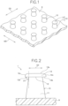
- Fig. 1 is a perspective view illustrating a molded surface fastener according to a first embodiment.
- Figs. 2 and 3 are a front view and a plan view illustrating an engaging element of the first embodiment, respectively.
- the front-back direction of a molded surface fastener and a primary molded body refers to the length direction of the molded surface fastener and the primary molded body that are molded in an elongated manner as described later, and also refers to a first direction along a machine direction (MD) in which the molded surface fastener or the primary molded body is transported in the manufacturing process of the molded surface fastener.
- MD machine direction
- the left-right direction refers to a width direction that is orthogonal to the length direction and is along the upper surface (or lower surface) of a base portion of the molded surface fastener.
- the left-right direction and the width direction can also be referred to as a cross direction (CD) or a second direction that is orthogonal to the machine direction (MD).
- the upper-lowerl direction (thickness direction) refers to a height direction (height direction of engaging element) that is orthogonal to the length direction and is also orthogonal to the upper surface (or lower surface) of the base portion of the molded surface fastener.
- a molded surface fastener 1 according to the first embodiment is manufactured in a rectangular shape that is long in the machine direction MD of a manufacturing apparatus 20 in a plan view by using the manufacturing apparatus 20 that includes a molding device 21 and a heat-press device 28, which will be described later in Fig. 4 .
- the length dimension (dimension in machine direction MD) and width dimension (dimension in cross direction CD) of the molded surface fastener 1 according to the invention are not particularly limited, and can be freely changed by cutting the molded surface fastener 1 or the like.
- the molded surface fastener 1 may have a shape other than a rectangle in a plan view.
- the molded surface fastener 1 according to the first embodiment is made of a thermoplastic resin whose MFR and flexural modulus fall within a predetermined range, as described later.
- a thermoplastic resin such as polypropylene, polyester, nylon, polybutylene terephthalate, or a copolymer of them can be adopted as the synthetic resin forming the molded surface fastener 1.
- the molded surface fastener 1 according to the first embodiment is made of polypropylene.
- the molded surface fastener 1 includes a base portion 9 with a thin flat plate shape and a plurality of engaging elements 10 that stand vertically on an upper surface of the base portion 9 and have a mushroom shape.
- the base portion 9 is formed long along the machine direction MD at the time of manufacturing the molded surface fastener 1.
- the base portion 9 has a predetermined thickness that can achieve a suitable strength, and the upper surface and lower surface of the base portion 9 are formed to be flat and parallel to each other.
- the engaging element 10 of the first embodiment includes a stem portion 11 standing from the base portion 9 and an engaging head portion 12 that is integrally formed on the stem portion 11 and has a disc shape or a dish shape so as to extend outward from the entire circumference of an upper end portion of the stem portion 11.
- the stem portion 11 is formed so as to extend in a direction orthogonal to the upper surface of the base portion 9. Further, the stem portion 11 has a truncated cone shape in which the area of a cross-section orthogonal to the upper-lowerl direction gradually increases as approaching the base portion 9.
- the shape of the stem portion 11 is not limited to a truncated cone shape, and may have, for example, a truncated pyramid shape such as a truncated square pyramid, a columnar shape, or a prism shape such as a quadrangular prism.
- the engaging head portion 12 of the first embodiment is integrally formed on the stem portion 11 with a boundary portion 13 interposed between the engaging head portion 12 and the stem portion 11.
- This engaging head portion 12 is relatively short in vertical dimension (that is, thickness), and has a circular shape in the plan view illustrated in Fig. 3 in which the engaging element 10 is viewed from above.
- the circular shape of the engaging head portion 12 that can be checked in a plan view is formed to have a diameter larger than that of the circle formed by the boundary portion 13 in a plan view.
- the diameter of the circular engaging head portion 12 in a plan view is preferably 110% or more and 200% or less of the diameter of the circle formed by the boundary portion 13.
- the engaging head portion 12 of the first embodiment includes a flat head-portion top end surface 12a that is exposed upward, a back-side proximal end surface 12b that extends from the boundary portion 13 with the stem portion 11 toward the outside of the stem portion 11, and an outer peripheral side surface 12c that is formed in a curved surface shape that is inclined downward from an outer peripheral edge of the head-portion top end surface 12a to an outer peripheral edge of the back-side proximal end surface 12b.
- the head-portion top end surface 12a of the engaging head portion 12 is disposed to be parallel to the upper surface of the base portion 9, and the width dimension (width dimension of flat surface portion) in the cross direction CD of the head-portion top end surface 12a, which is formed flat, is equal to or larger than the width dimension in the cross direction CD of the stem portion 11 at the boundary portion 13. Further, the length dimension (length dimension of flat surface portion) in the machine direction MD of the head-portion top end surface 12a, which is formed flat, is equal to or larger than the length dimension in the machine direction MD of the stem portion 11 at the boundary portion 13.
- the outer peripheral side surface 12c with a curved surface shape is formed over the entire circumferential direction of the engaging head portion 12 between the head-portion top end surface 12a and the back-side proximal end surface 12b.
- the back-side proximal end surface 12b of the engaging head portion 12 is disposed on the opposite side to the head-portion top end surface 12a in the upper-lowerl direction so as to face the base portion 9.
- the back-side proximal end surface 12b is formed in a donut shape or a ring shape surrounding the stem portion 11. Further, as illustrated in Fig.
- the surface of the back-side proximal end surface 12b along the cross direction CD is formed to make a back surface angle ⁇ 1 of 70° or more and 110° or less, preferably 70° or more 90° or less with respect to the height direction (upper-lowerl direction) of the stem portion 11.
- the back surface angle ⁇ 1 refers to the angle at which the surface of the back-side proximal end surface 12b on a side of an end portion connected to the boundary portion 13 with the stem portion 11, is inclined with respect to the upper-lowerl direction.
- the back surface angle ⁇ 1 is set to 70° or more as described above, loops of a loop member such as a non-woven fabric can easily enter the back side of the engaging head portion 12 and be easily caught. Moreover, as the back surface angle ⁇ 1 is set to 110° or less (in particular, 90° or less), in a case where the loops of the loop member are caught on the back side of the engaging head portion 12 and engaged with the back side, the engaged loops can be stably held and the loops can hardly be removed from the engaging element 10.
- the back surface angle ⁇ 1 of the back-side proximal end surface 12b is 90° (including error of about ⁇ 5%), and the back-side proximal end surface 12b of the engaging head portion 12 is disposed to be parallel to the upper surface of the base portion 9 and the head-portion top end surface 12a of the engaging head portion 12.
- the back-side proximal end surface 12b of the engaging head portion 12 is formed to make a back surface angle ⁇ 1 of 90° with respect to the upper-lowerl direction not only on the surface along the cross direction CD but also over the entire circumference of the engaging head portion 12.
- the back-side proximal end surface 12b has a plane that shows a straight line in the range from the boundary portion 13 with the stem portion 11 to the boundary portion 13 with the outer peripheral side surface 12c.
- the back-side proximal end surface 12b is formed in a single flat plane shape over the entire circumference of the engaging head portion 12.
- the plane portion of the back-side proximal end surface 12b is formed with a length of 20 ⁇ m or more and 90 ⁇ m or less, in particular, 40 ⁇ m or more and 90 ⁇ m or less along the cross direction CD. Since the plane portion of the back-side proximal end surface 12b has a length of 20 ⁇ m or more (in particular, 40 ⁇ m or more), loops of a loop member that is generally used in disposable diapers or the like can be easily caught on the engaging head portion 12 of the engaging element 10, and the hooked loop can be stably held by the engaging element 10.
- the plane portion of the back-side proximal end surface 12b has a length of 90 ⁇ m or less, it is possible to prevent the engaging head portion 12 from becoming too large.
- a space of a suitable size can be stably formed between adjacent engaging elements 10 each other.
- the plane portion of the back-side proximal end surface 12b is formed over the entire back-side proximal end surface 12b, and this plane portion has a length of 40 ⁇ m along the cross direction CD. Moreover, in the engaging head portion 12 of the first embodiment, the length of the plane portion of the back-side proximal end surface 12b along its radial direction is substantially the same over the entire circumference of the engaging head portion 12.
- the back-side proximal end surface 12b of the engaging head portion 12 may be formed in a curved surface shape that is curved to project along the radial direction of the engaging head portion 12.
- a portion in which the radial direction of the engaging head portion 12 is along the cross direction CD may be formed in a flat plane surface shape
- a portion in which the radial direction of the engaging head portion 12 is along the machine direction MD may be formed in a curved surface shape.
- the molded surface fastener 1 according to the first embodiment is manufactured by using the manufacturing apparatus 20 illustrated in Fig. 4 .
- This manufacturing apparatus 20 includes the molding device 21 that performs a primary molding step and the heat-press device 28 that heats a primary molded body 1a that is molded in the primary molding step and will be described later, and presses a part of the primary molded body 1a.
- the molding device 21 of the first embodiment includes a die wheel 22 that is driven to rotate in one direction (counterclockwise in Fig. 4 ), a nozzle portion 23 that is disposed to face a peripheral surface of the die wheel 22 and continuously pours a molten synthetic resin material into the die wheel 22, and a pickup roller 24 that is disposed on the downstream side of the nozzle portion 23 in the rotating direction of the die wheel 22.
- the die wheel 22 includes a cylindrical body (sleeve) 25 that is a die member and a rotating drive roller 26 that rotates the cylindrical body 25 in one direction.
- a cooling jacket (not illustrated) in which a cooling liquid flows is provided inside the rotating drive roller 26, so that the primary molded body 1a that is molded on the outer peripheral surface of the die wheel 22 and will be described later can be cooled efficiently.
- the cylindrical body 25 of the die wheel 22 has a plurality of through-holes 25a penetrating the cylindrical body 25 from the outer peripheral surface to the inner peripheral surface of the cylindrical body 25 as cavities for molding a temporary element 15 of the primary molded body 1a, which will be described later.
- These through-holes 25a are formed to correspond to the arrangement positions of the engaging elements 10 of the molded surface fastener 1 to be manufactured.
- each through-hole 25a has a truncated cone shape in which a circle formed on the outer peripheral surface of the cylindrical body 25 is larger than a circle formed on the inner peripheral surface of the cylindrical body 25.
- the material and size of the cylindrical body 25 and the method for forming the cylindrical body 25 are not particularly limited.
- the pickup roller 24 of the molding device 21 includes paired upper holding roller 24a and lower holding roller 24b that vertically hold and pull the primary molded body 1a molded on the outer peripheral surface portion of the die wheel 22.
- the upper holding roller 24a and the lower holding roller 24b are arranged so as to face each other with a predetermined distance from each other.
- a surface layer (not illustrated) made of an elastomer such as a polyurethane elastomer is formed on each of the outer peripheral surface portions of the upper holding roller 24a and the lower holding roller 24b.
- the heat-press device 28 includes paired upper pressing roller (upper calendar roller) 28a and lower pressing roller (lower calendar roller) 28b that are arranged on the downstream side of the pickup roller 24.
- the upper pressing roller 28a and the lower pressing roller 28b are arranged to face to each other with a predetermined distance from each other for the purpose of pressing the temporary elements 15 of the primary molded body 1a molded by the molding device 21 in the upper-lowerl direction and reducing the height dimension (dimension in upper-lowerl direction) to a predetermined dimension.
- the distance between the upper pressing roller 28a and the lower pressing roller 28b can be adjusted by a height adjustment unit (not illustrated).
- the upper pressing roller 28a is arranged so as to rotate counterclockwise in Fig. 4 .
- the size of the upper pressing roller 28a is not particularly limited, and the diameter (roller diameter) of the upper pressing roller 28a in a cross-section orthogonal to the rotating axis direction of the upper pressing roller 28a is freely set.
- the upper pressing roller 28a includes a heating source (not illustrated) therein, and the outer peripheral surface of the upper pressing roller 28a heats the temporary element 15 of the primary molded body 1a at a predetermined heating temperature and at the same time, presses the temporary element 15 from above.
- the lower pressing roller 28b is arranged so as to rotate clockwise in Fig. 4 , and supports the primary molded body 1a pressed by the upper pressing roller 28a from below.
- the primary molding step of molding the primary molded body 1a by the molding device 21 is performed first.
- a molten synthetic resin material is continuously ejected from the nozzle portion 23 toward the outer peripheral surface portion of the rotating die wheel 22.
- thermoplastic resin having an MFR of 20 g/10min or more and 60 g/10min or less (preferably, 40 g/10min or more and 60 g/10min or less) and a flexural modulus of 1000 MPa or more and 2300 MPa or less (preferably, 1000 MPa or more and 1500 MPa or less) is used as the synthetic resin supplied from the nozzle portion 23 to the die wheel 22.
- the MFR of the thermoplastic resin is 20 g/10min or more (preferably, 40 g/10min or more), when the upper end portion of the temporary element 15 is heated and pressed to be molded into the engaging head portion 12 in a secondary molding step to be described later, a part of the temporary element 15 can be easily softened and deformed at a predetermined heating temperature.
- the engaging element 10 can be formed so that the engaging head portion 12 of the engaging element 10 is made thin and the back surface angle ⁇ 1 of the back-side proximal end surface 12b of the engaging head portion 12 falls within a predetermined range.
- the MFR of the thermoplastic resin is 60 g/10min or less, it is possible to suppress the temporary element 15 from being deformed suddenly when the temporary element 15 is heated and pressed in the secondary molding step, and thus the shape of the engaging element 10 subjected to secondary molding can be stabilized.
- the flexural modulus of the thermoplastic resin is 1000 MPa or more, it is possible to suppress the temporary element 15 from being deformed suddenly in the secondary molding step, and the shape of the engaging element 10 subjected to secondary molding can be stabilized. Moreover, since the rigidity of the engaging element 10 can be properly secured, it is possible to prevent the peel strength of the molded surface fastener 1 from decreasing due to the rigidity of the engaging element 10.
- the temporary element 15 can be properly and quickly deformed at a predetermined heating temperature in the secondary molding step, and thus it is possible to stably form the engaging element 10 so that the engaging head portion 12 that is thin and flat is provided and the back surface angle ⁇ 1 of the engaging head portion 12 falls within a predetermined range.
- polypropylene having an MFR of 40 g/10min and a flexural modulus of 1300 MPa is used as the synthetic resin forming the molded surface fastener 1.
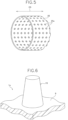
- polypropylene with the properties described above, which is in a molten state, is continuously extruded from the nozzle portion 23, and thus the primary molded body 1a in which a plurality of temporary element 15 (sometimes referred to as "temporary stem portions") illustrated in Fig. 6 are provided upright on the upper surface of the base portion 9 is molded.
- the base portion 9 is formed to be elongated in the machine direction between the nozzle portion 23 and the die wheel 22.
- the through-holes 25a formed in the cylindrical body 25 of the die wheel 22 is filled with the thermoplastic resin, and thus the temporary elements 15 with a truncated cone shape are integrally molded with the base portion 9.
- the primary molded body 1a is cured by half-rotating while being supported and cooled on the outer peripheral surface portion of the die wheel 22. Thereafter, the cured primary molded body 1a is continuously peeled off from the outer peripheral surface portion of the die wheel 22 by the pickup roller 24.
- the temporary element 15 of the primary molded body 1a after being peeled off from the die wheel 22 has a height dimension of 150 ⁇ m to 400 ⁇ m.
- the height dimension of the temporary element 15 refers to the dimension in the upper-lowerl direction from the upper surface of the base portion 9 to the circular top end surface (upper end surface) of the temporary element 15.
- the primary molded body 1a peeled off from the die wheel 22 is transported toward the heat-press device 28 that performs the secondary molding step, and then is introduced between the upper pressing roller 28a and the lower pressing roller 28b in the heat-press device 28.
- the upper pressing roller 28a heats at least the upper end portion of the temporary element 15 of the primary molded body 1a, and at the same time presses the temporary element 15 from above to crush the upper end portion of the temporary element 15.
- the upper pressing roller 28a heats the temporary element 15 at a fixed heating temperature that is a first temperature or higher, the first temperature being lower than the melting point of a synthetic resin by 50°C, and a second temperature or lower, the second temperature being lower than the melting point of the synthetic resin by 20°C.
- the temporary element 15 is heated by the upper pressing roller 28a at a heating temperature of 110°C or higher and 150°C or lower.
- the heating temperature of the upper pressing roller 28a is set to 140°C.
- the amount of crushing of the temporary element 15 by the heat-press device 28 (in other words, difference in height dimension between temporary element 15 and engaging element 10) is set to 20 ⁇ m or more and 80 ⁇ m or less. That is, the secondary molding step is performed so that when the height dimension of the temporary element 15 before being introduced into the heat-press device 28 is compared with the height dimension of the engaging element 10 after being molded by the heat-press device 28 from the base portion 9, the height dimension of the engaging element 10 is less than the height dimension of the temporary element 15 by 20 ⁇ m or more and 80 ⁇ m or less.
- the height dimension of the engaging element 10 refers to the dimension in the upper-lowerl direction from the upper surface of the base portion 9 to the flat top end surface (upper end surface) of the engaging head portion 12.
- the amount of crushing by the heat-press device 28 is preferably 5% or more and 40% or less of the height dimension of the temporary element 15 before being pressed.
- polypropylene having a predetermined MFR and flexural modulus described above is used as the material of the molded surface fastener 1, and the secondary molding step is performed under predetermined molding conditions described above.
- the molded surface fastener 1 having a characteristic shape in which the engaging head portion 12 of the engaging element 10 is formed in a flat and thin shape, and the back-side proximal end surface 12b is inclined at a predetermined angle with respect to the upper-lowerl direction.
- the back surface angle ⁇ 1 of the engaging head portion 12 is 70° or more and 110° or less, and the back-side proximal end surface 12b has a plane portion of 20 ⁇ m or more along the radial direction of the engaging head portion 12. Consequently, when a loop member such as a non-woven fabric is engaged with the molded surface fastener 1 according to the first embodiment, the loops caught on the engaging head portion 12 of the engaging element 10 can be hardly removed from the engaging element 10. As a result, the molded surface fastener 1 according to the first embodiment has a high peel strength (engagement strength) with respect to the loop member. In addition, since the top end surface of the engaging head portion 12 is formed flat in the molded surface fastener 1 according to the first embodiment, the good texture can be achieved on the upper surface side of the fastener on which a plurality of the engaging elements 10 are formed.
- polypropylene having an MFR of 40 g/10min and a flexural modulus of 1300 MPa is used as the synthetic resin forming the molded surface fastener 1, and the heating temperature of the upper pressing roller 28a in the secondary molding step is set to 140°C.
- the heating temperature of the upper pressing roller 28a in the secondary molding step is set to 140°C.
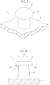
- a molded surface fastener 2 that includes an engaging element 30 of a first modification illustrated in Figs. 7 and 8 and a molded surface fastener 3 that includes an engaging element 40 of a second modification illustrated in Fig. 9 .
- polypropylene having an MFR of 50 g/10min and a flexural modulus of 1050 MPa is used as the synthetic resin forming the molded surface fastener 2.
- the heating temperature of the upper pressing roller 28a is set to 130°C. Consequently, in the molded surface fastener 2 manufactured in the first modification, the overall height dimension of the engaging element 30 is less than that of the engaging element 10 of the first embodiment illustrated in Figs. 1 to 3 .
- an engaging head portion 32 is formed thicker than the one in the first embodiment, and the diameter of the circular engaging head portion 32 of the engaging element 30 in a plan view is larger than the one in the first embodiment.
- the back surface angle ⁇ 1 of a back-side proximal end surface 32b of the engaging head portion 32 with respect to the upper-lowerl direction is set to 70° or more and 110° or less, specifically 90° (including error of about ⁇ 5%), similarly to the engaging element 10 of the first embodiment.
- the back-side proximal end surface 32b of the engaging head portion 32 is formed in a single flat plane shape over the entire circumference of the engaging head portion 32.
- the plane portion of the back-side proximal end surface 32b has a length of 20 ⁇ m or more, specifically 50 ⁇ m along the radial direction of the engaging head portion 12.
- the loops caught on the engaging head portion 32 of the engaging element 30 can be hardly removed from the engaging element 30, and thus the molded surface fastener 2 can have a high peel strength with respect to the loop member.
- polypropylene having an MFR of 40 g/10min or more and 60 g/10min or less and a flexural modulus of 1000 MPa or more and 1500 MPa or less is also used as the material of the molded surface fastener 3.
- the heating temperature of the upper pressing roller 28a is set to 110°C or higher and 150°C or lower in the secondary molding step.
- the back surface angle ⁇ 1 of a back-side proximal end surface 42b of an engaging head portion 42 with respect to the upper-lowerl direction is 70° or more and 90° or less.
- the plane portion of the back-side proximal end surface 42b of the engaging head portion 42 has a length of 20 ⁇ m or more. Consequently, the molded surface fastener 3 including the engaging element 40 of the second modification can also have a high peel strength with respect to the loop member, similarly to the molded surface fastener 1 according to the first embodiment.
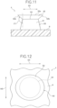
- Fig. 10 is a perspective view illustrating a molded surface fastener according to a second embodiment.
- Figs. 11 and 12 are a front view and a plan view illustrating an engaging element of the second embodiment, respectively.
- a molded surface fastener 4 according to the second embodiment is made of a thermoplastic resin having an MFR of 1 g/10min or more and 60 g/10min or less and a flexural modulus of 1600 MPa or more and 3000 MPa or less.
- a thermoplastic resin having an MFR of 1 g/10min or more and 60 g/10min or less and a flexural modulus of 1600 MPa or more and 3000 MPa or less.
- polypropylene, polyester, nylon, polybutylene terephthalate, a copolymer of them, or the like can be used as the thermoplastic resin.
- the molded surface fastener 4 is made of polypropylene having an MFR of 10 g/10min and a flexural modulus of 2000 MPa, and the MFR value of polypropylene is less than the lower limit of the MFR numerical range described in the first embodiment.
- the molded surface fastener 4 according to the second embodiment includes the base portion 9 with a thin flat plate shape and a plurality of engaging elements 50 that stand vertically on an upper surface of the base portion 9 and have a mushroom shape.
- the base portion 9 is formed similarly to the base portion 9 of the molded surface fastener 1 according to the first embodiment.
- the engaging element 50 of the second embodiment includes a stem portion 51 standing from the base portion 9 and an engaging head portion 52 that is integrally formed on the stem portion 51 and is formed to extend outward from the entire circumference of an upper end portion of the stem portion 51.
- the stem portion 51 has a truncated cone shape in which the area of a cross-section orthogonal to the upper-lowerl direction gradually increases as approaching the base portion 9.
- the engaging head portion 52 of the second embodiment is integrally formed on the stem portion 51 with a boundary portion 53 interposed between the engaging head portion 52 and the stem portion 51.
- the engaging head portion 52 is formed in a long elliptical shape in the cross direction CD in the plan view ( Fig. 12 ) in which the engaging element 50 is viewed from above.
- the dimension of a major axis of the engaging head portion 52 along the cross direction CD is 110% or more and 200% or less, preferably 120% or more and 150% or less of the dimension of a minor axis of the engaging head portion 52 along the machine direction MD.
- the engaging head portion 52 of the second embodiment includes a head-portion top end surface 52a that is exposed upward and a back-side proximal end surface 52b that extends outward from the boundary portion 53 with the stem portion 51.
- the head-portion top end surface 52a of the engaging head portion 52 is formed to be flat and parallel to the upper surface of the base portion 9.
- the back-side proximal end surface 52b of the engaging head portion 52 is disposed on the opposite side to the head-portion top end surface 52a in the upper-lowerl direction so as to face the base portion 9, and is formed in a ring shape surrounding the stem portion 51. Further, as illustrated in Fig. 11 , in a front view when the engaging element 50 is viewed from the side of the machine direction MD, the back-side proximal end surface 52b is formed to make a back surface angle ⁇ 1 of 120° or more respect to the height direction (upper-lowerl direction) of the stem portion 51.
- the molded surface fastener 4 according to the second embodiment described above is manufactured by using the manufacturing apparatus 20 that includes the molding device 21 and the heat-press device 28 illustrated in Fig. 4 , as in the case of the first embodiment described above.
- the heat-press device 28 of the second embodiment has paired upper pressing roller 28a and lower pressing roller 28b, but a roller whose diameter (roller diameter) in a cross-section orthogonal to a rotating axis direction is 300 mm or more and 500 mm or less is used as the upper pressing roller 28a.
- the upper pressing roller 28a has a diameter of 400 mm.
- the upper pressing roller 28a By using the upper pressing roller 28a with such a diameter, it is possible to easily and stably mold the elliptical engaging head portion 52 in which the lengths of the major axis and the minor axis have a predetermined ratio as described above from a temporary element 55 with a truncated cone shape, which will be described later. In this case, by using the upper pressing roller 28a with a larger diameter, it is possible to form the elliptical engaging head portion 52 in which the ratio of the dimension of the major axis along the cross direction CD to the dimension of the minor axis along the machine direction MD becomes larger.
- the primary molding step of molding a primary molded body 4a illustrated in Fig. 13 is performed first by the molding device 21.
- the thermoplastic polypropylene having an MFR of 10 g/10min and a flexural modulus of 2000 MPa is used as the synthetic resin supplied from the nozzle portion 23 to the die wheel 22.
- the engaging element 50 in which the back surface angle ⁇ 1 of the engaging head portion 52 is 120° or more and high rigidity is achieved is molded.
- the engaging head portion 52 can be easily formed in an elliptical shape in the plan view of the engaging element 50.
- any thermoplastic resin having an MFR of 1 g/10min or more and 60 g/10min or less and a flexural modulus of 1600 MPa or more and 3000 MPa or less can be selected and used as the material of the molded surface fastener 4.
- the primary molding step and the secondary molding step as follows using the selected thermoplastic resin, it is possible to manufacture the molded surface fastener 4 according to the second embodiment in which the engaging head portion 52 has an elliptical shape in the plan view of the engaging element 50.
- the primary molding step is performed similarly to the primary molding step of the first embodiment described above, except that the synthetic resin used as the material is different.
- the primary molded body 4a in which a plurality of temporary elements 55 illustrated in Fig. 13 are provided upright on the upper surface of the base portion 9 is molded.
- the temporary element 55 molded in the second embodiment has a similar shape to the temporary element 15 molded in the first embodiment described above.
- the primary molded body 4a obtained in the primary molding step is transported toward the heat-press device 28 that performs the secondary molding step, and then is introduced between the upper pressing roller 28a and the lower pressing roller 28b in the heat-press device 28.
- the upper pressing roller 28a heats at least the upper end portion of the temporary element 55 of the primary molded body 4a, and at the same time presses the temporary element 55 from above.
- the upper pressing roller 28a heats the temporary element 55 at a fixed heating temperature that is a first temperature or higher, the first temperature being lower than the melting point of a synthetic resin by 50°C, and a second temperature or lower, the second temperature being lower than the melting point of the synthetic resin by 20°C, as in the case of the first embodiment described above.
- the heating temperature of the upper pressing roller 28a is set to 138°C.
- the amount of crushing of the temporary element 55 by the heat-press device 28 is set to 20 ⁇ m or more and 80 ⁇ m or less.
- polypropylene having a predetermined MFR and flexural modulus described above is used as the material of the molded surface fastener 4, and the secondary molding step is performed under predetermined conditions using the upper pressing roller 28a with a diameter of 300 mm or more and 500 mm or less as described above.
- the engaging head portion 52 of the engaging element 50 has a characteristic shape (that is, shape that is predetermined elliptical shape in plan view and has back surface angle ⁇ 1 of 120° or more).
- the engaging head portion 52 has an elliptical shape in the plan view of the engaging element 50.
- the molded surface fastener 4 is made of polypropylene having a high flexural modulus, for example, a flexural modulus of 2000 MPa, and the rigidity of each engaging element 50 is enhanced.
- the molded surface fastener 4 according to the second embodiment has a high peel strength (engagement strength) with respect to the loop member.
- the flat head-portion top end surface 52a of the engaging head portion 52 is more likely to be formed wider than the one in the molded surface fastener 1 according to the first embodiment described above, and thus a better texture on the upper surface side of the fastener can be achieved.
- the molded surface fastener 1 illustrated in Figs. 1 to 3 was manufactured under the conditions described in the first embodiment described above. That is, the molded surface fastener 1 according to the first example was manufactured by using polypropylene having an MFR of 40 g/10min and a flexural modulus of 1300 MPa as the synthetic resin forming the molded surface fastener 1 and setting the heating temperature of the upper pressing roller 28a in the secondary molding step to 140°C.
- the back surface angle ⁇ 1 of the back-side proximal end surface 12b along the radial direction of the engaging head portion 12 and the cross direction CD is 90°
- the back-side proximal end surface 12b has a plane portion of 40 ⁇ m along the radial direction of the engaging head portion 12.
- the molded surface fastener 2 illustrated in Figs. 7 and 8 was manufactured under the conditions described in the first modification of the first embodiment described above. That is, the molded surface fastener 2 according to the second example was manufactured by using polypropylene having an MFR of 50 g/10min and a flexural modulus of 1050 MPa as the synthetic resin forming the molded surface fastener 2 and setting the heating temperature of the upper pressing roller 28a in the secondary molding step to 130°C.
- the back surface angle ⁇ 1 of the back-side proximal end surface 32b along the radial direction of the engaging head portion 32 and the cross direction CD is 90°
- the back-side proximal end surface 32b has a plane portion of 50 ⁇ m along the radial direction of the engaging head portion 32.
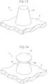
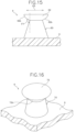
- the molded surface fastener 5 according to the first comparative example illustrated in Figs. 14 and 15 was manufactured in a manner that a molded surface fastener was manufactured by using polypropylene having an MFR of 10 g/10min and a flexural modulus of 2000 MPa as the synthetic resin and setting the heating temperature of the upper pressing roller 28a in the secondary molding step to 130°C. Conditions other than the MFR and flexural modulus of polypropylene and the heating temperature of the upper pressing roller 28a were set similarly to those of the first example (first embodiment).
- the molded surface fastener 5 manufactured in the first comparative example had a plurality of engaging elements 60 illustrated in Figs. 14 and 15 . Further, in the case of the first comparative example, the back surface angle ⁇ 1 of a back-side proximal end surface 62b along the radial direction of an engaging head portion 62 and the cross direction CD was 120°. Moreover, a plane portion was not formed on the back-side proximal end surface 62b of the engaging head portion 62 (that is, length of plane portion on back-side proximal end surface 62b of engaging head portion 62 along radial direction on was 0 ⁇ m).
- the molded surface fastener 4 illustrated in Figs. 10 to 12 was manufactured under the conditions described in the second embodiment described above. That is, polypropylene having an MFR of 10 g/10min and a flexural modulus of 2000 MPa was used as the synthetic resin forming the molded surface fastener 4. Further, the molded surface fastener 4 according to the third example was manufactured by using the upper pressing roller 28a with a diameter of 400 mm and setting the heating temperature of the upper pressing roller 28a to 138°C in the secondary molding step.
- the back surface angle ⁇ 1 of the back-side proximal end surface 52b along the radial direction of the engaging head portion 52 and the cross direction CD was 120° or more.
- the engaging head portion 52 had a long elliptical shape in the cross direction CD in the plan view of the engaging element 50, and the dimension of the major axis of the engaging head portion 52 along the cross direction CD was 122% of the dimension of the minor axis of the engaging head portion 52 along the machine direction MD.
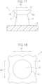
- a second comparative example the same polypropylene as that used in the third example, that is, polypropylene having an MFR of 10 g/10min and a flexural modulus of 2000 MPa was used as the synthetic resin. Further, a molded surface fastener 6 according to the second comparative example illustrated in Figs. 16 to 18 was manufactured by using the upper pressing roller 28a with a diameter of 100 mm and setting the heating temperature of the upper pressing roller 28a to 135°C in the secondary molding step. Conditions other than the diameter and heating temperature of the upper pressing roller 28a were set similarly to those of the third example (second embodiment).
- the molded surface fastener 6 manufactured in the second comparative example had a plurality of engaging elements 70 illustrated in Figs. 16 to 18 .
- the back surface angle ⁇ 1 of a back-side proximal end surface 72b along the radial direction of an engaging head portion 72 and the cross direction CD was 120° or more.
- the engaging head portion 72 had a circular shape in the plan view of the engaging element 70, and the dimension of the engaging head portion 72 along the cross direction CD was 98% of the dimension of the engaging head portion 72 along the machine direction MD.
- each of the molded surface fasteners 1, 2, 4, 5, and 6 according to the first to third examples and the first and second comparative examples was cut in a size of 25 mm in the machine direction MD ⁇ 25 mm in the cross direction CD.
- a cut piece 83 of the molded surface fastener cut was then adhesively fixed to a support member 84 made of a non-woven fabric, so that a first test piece 81 on a molded surface fastener side was prepared.
- a non-woven fabric 85 larger in size in the machine direction MD than the cut piece 83 of the molded surface fastener was adhesively fixed to the support member 84, so that a second test piece 82 on a loop member side was prepared.
- the cut piece 83 of the molded surface fastener on the first test piece 81 was engaged with the second test piece 82. Subsequently, the first test piece 81 and the second test piece 82 were each gripped by paired clampers (not illustrated), and then the paired clampers gripping the first test piece 81 and the second test piece 82 were moved at a constant speed so as to be separated from each other, so that a load was gradually applied to the first test piece 81 and the second test piece 82 in an engaged state. The peel strength of each of the molded surface fasteners 1, 2, 4, 5, and 6 was determined by measuring the load when the engaged state was released.
- the molded surface fasteners 1 and 2 according to the first and second examples have a peel strength three times or more higher than that of the molded surface fastener 5 according to the first comparative example.
- the molded surface fastener 4 according to the third example has a peel strength five times or more higher than that of the molded surface fastener 6 according to the second comparative example.
- the first embodiment and the second embodiment described above describe the case where the primary molding step of the molded surface fastener is performed by using the molding device 21 having the die wheel 22 illustrated in Fig. 4 .
- a molding device that molds a primary molded body
- a molding device that includes a die wheel that is driven to rotate in one direction, a press wheel that is arranged with a predetermined distance between the press wheel and the die wheel and that is driven to rotate in the opposite direction to the die wheel, and a nozzle portion that pours a molten synthetic resin between the die wheel and the press wheel.
- the die wheel disposed in the twin wheel molding device has the structure similar to that of the die wheel 22 illustrated in Fig. 4 , which is used in the first embodiment described above.
- the molded surface fastener according to the first embodiment or the second embodiment described above can also be stably manufactured.
Landscapes
- Engineering & Computer Science (AREA)
- Mechanical Engineering (AREA)
- Health & Medical Sciences (AREA)
- Heart & Thoracic Surgery (AREA)
- Epidemiology (AREA)
- Biomedical Technology (AREA)
- Manufacturing & Machinery (AREA)
- Vascular Medicine (AREA)
- Life Sciences & Earth Sciences (AREA)
- Animal Behavior & Ethology (AREA)
- General Health & Medical Sciences (AREA)
- Public Health (AREA)
- Veterinary Medicine (AREA)
- Slide Fasteners, Snap Fasteners, And Hook Fasteners (AREA)
Description
- The invention relates to a method for manufacturing a molded surface fastener having a plurality of engaging elements provided on a base portion, and a molded surface fastener manufactured by the manufacturing method.
- Conventionally, there has been known surface fastener products in which a loop member (female surface fastener) having a plurality of loops and a male molded surface fastener that is attachable to and detachable from the loop member are used as a pair. In the male molded surface fastener manufactured by, for example, molding a synthetic resin, a plurality of male engaging elements with a mushroom shape or the like are provided upright on the upper surface of a flat plate-like base portion.
- The surface fastener product having such a male surface fastener is currently used for a wide variety of commercial products including products attached to and detached from the human body such as disposable diapers, infant diaper covers, supporters for protecting limb joints, lumber corsets (back support belts), and gloves.
- Further, an example of a method for manufacturing a surface fastener having a plurality of male engaging elements with a mushroom shape or a J-shape is described in, for example,
JP 3515117 B1 Patent Document 1 corresponding toJP 8-508910 A JP 4168182 B1 Patent Document 2 corresponding toJP 2002-504006 A - In the manufacturing methods described in
Patent Document 1 andPatent Document 2, a primary molding step of molding a primary molded body having a flat plate-like base portion and a plurality of primary stem portions (temporary elements) that are provided upright on the base portion is performed first. Thereafter, a secondary molding step is performed, in which the resultant primary molded body is caused to pass between calendar rolls (heat-press rolls), which are vertically paired, so that a part of the primary stem portions formed in the primary molded body are hated and pressed. - With this secondary molding step, the primary stem portion (temporary element) is transformed into a mushroom-shaped engaging element having a stem portion and an engaging head portion integrally formed on the stem portion, or a J-shaped engaging element having a stem portion and an engaging head portion bent to extend from the upper end portion of the stem portion. As a result, it is possible to easily manufacture a surface fastener including a plurality of engaging elements with a predetermined shape.
- Particularly in the manufacturing method of
Patent Document 1, as the set speed at which the primary molded body is inserted, the dimension of a gap for inserting the primary molded body between the upper and lower calendar rolls, and the heating capacity of a calendar roll surface are controlled in the secondary molding step, it is possible to manufacture a surface fastener having a plurality of mushroom-shaped engaging elements in which the top end surface (upper end surface) of an engaging head portion is formed in a slightly recessed shape.Patent Document 1 describes that as the engaging element has the shape described above, excellent engagement force in a shear direction with the loop member can be achieved and low-cost manufacturing can also be achieved. - In the manufacturing method of
Patent Document 2, the surface of the upper calendar roll used in the secondary molding step includes a plurality of recessed grooves (valleys) formed along one direction. As the secondary molding step is performed by using such a calendar roll having the plurality of recessed grooves, it is possible to manufacture a surface fastener having a plurality of engaging elements bent in a J-shape or a plurality of engaging elements in which the engaging head portion is formed long in a machine direction and a plurality of linear recesses are formed on the top end surface (upper end surface) of the engaging head portion from the first stem portions of the primary molded body.Patent Document 2 describes that as the calendar roll in the secondary molding step has a plurality of recessed grooves, it is possible to obtain an engaging element that has increased engagement with the loop member. -
US2005/202205 A1 discloses a method of manufacturing a stretched mechanical fastening web laminate ( 1 ) comprising a thermoplastic web layer ( 13 ) having two major surfaces, one of the major surfaces bearing a multitude of male fastening elements ( 14 ) suitable for engagement with a corresponding female fastening material, and on its other major surface a fibrous web layer ( 11 ). -
US2006/096071 A1 discloses a system and method for manufacturing a substrate having a bed of hooks located therein, in particular a system or manufacturing a hook plate having hooks with enlarged shaped heads. The system can include the use of a heated generally flat coining plate, a resilient layer placed under the hook plate, and a forming sheet placed between the coining plate and the tops of stems to be coined. -
WO2017/168757 A1 discloses a molded hook-and-loop fastener that has excellent balance of durability and peeling strength with respect to repeated attaching and detaching operations. The molded hook-and-loop fastener (100) is provided with a planar base portion (102) and a plurality of engaging elements (101) protruding from one main surface of the base portion (102), and is made of thermoplastic resin. -
- Patent Document 1:
JP 3515117 B1 - Patent Document 2:
JP 4168182 B1 - As described above, in the manufacturing methods of
Patent Document 1 andPatent Document 2, as specific molding conditions and specific shapes of calendar roll are adopted in the secondary molding step, an engaging element (in particular, engaging head portion) is formed in a characteristic shape, and thus the peel strength (engagement strength) of a molded surface fastener with respect to a loop member is improved. However, surface faster products are currently used for a variety of commercial products as described above, and some commercial products may require higher strength. Consequently, it is necessary to develop a molded surface fastener that has higher peel strength with respect to the loop member. - In addition, in the molded surface fastener manufactured by the manufacturing method of
Patent Document 1 orPatent Document 2, the upper end surface of each engaging element is not formed flat. For this reason, the upper surface side of the molded surface fastener, on which a plurality of engaging elements are provided, hardly has a good texture (good touch feeling), and thus there is still a room for improvement. - The invention has been made in view of the above conventional problems, and an object of the invention is to provide a method for manufacturing a molded surface fastener by which it is possible to form an engaging element in a shape capable of easily obtaining high peel strength and achieving a good texture on the upper surface side of the fastener, and a molded surface fastener manufactured by the manufacturing method.
- In order to achieve the above object, a method for manufacturing a molded surface fastener according to a first embodiment of the invention is a method for manufacturing a molded surface fastener that is made of a synthetic resin and has a plurality of engaging elements each of which includes a stem portion standing from a base portion and an engaging head portion integrally formed on the stem portion, the method including a primary molding step of molding a primary molded body having the base portion and a plurality of temporary elements provided upright on the base portion and a secondary molding step of heating at least a part of each of the temporary elements of the primary molded body and pressing the temporary elements from above to mold the molded surface fastener, being characterized in that the method comprises using a thermoplastic resin having a melt flow rate of 20 g/10min or more and 60 g/10min or less and a flexural modulus of 1000 MPa or more and 2300 MPa or less as the synthetic resin.
- A method for manufacturing a molded surface fastener according to a second embodiment of the invention is a method for manufacturing a molded surface fastener that is made of a synthetic resin and has a plurality of engaging elements each of which includes a stem portion standing from a base portion and an engaging head portion that has a disc shape and is integrally formed on the stem portion, the method including a primary molding step of molding a primary molded body having the base portion and a plurality of temporary elements provided upright on the base portion and a secondary molding step of heating at least a part of each of the temporary elements of the primary molded body and pressing the temporary elements from above to mold the molded surface fastener, being characterized in that the method comprises using a thermoplastic resin having a melt flow rate of 1 g/10min or more and 60 g/10min or less and a flexural modulus of 1600 MPa or more and 3000 MPa or less as the synthetic resin, and pressing the temporary elements from above by a pressing roller with a diameter of 300 mm or more and 500 mm or less in the secondary molding step.
- Further, in the method for manufacturing a molded surface fastener according to the invention, the method comprises molding the engaging element whose height dimension is less than the height dimension of the temporary element by 20 µm or more and 80 µm or less by heating at least a part of the temporary element at a heating temperature that is a first temperature or higher, the first temperature being lower than a melting point of the synthetic resin by 50°C, and a second temperature or lower, the second temperature being lower than the melting point of the synthetic resin by 20°C, and pressing the temporary element from above in the secondary molding step.
- Next, a molded surface fastener is disclosed made of a synthetic resin and has a plurality of engaging elements each of which includes a stem portion standing from a base portion and an engaging head portion integrally formed on the stem portion, wherein the engaging head portion has at least a top end surface that is exposed upward and formed flat and a back-side proximal end surface that is disposed on an opposite side to the top end surface and extends outward from a boundary portion with the stem portion, and at least a part of the back-side proximal end surface of the engaging head portion has an angle of 70° or more and 110° or less with respect to a height direction of the stem portion.
- Further, in a disclosed molded surface fastener the engaging head portion preferably has a circular shape in a plan view of the molded surface fastener, at least a part of the back-side proximal end surface of the engaging head portion preferably has a plane that shows a straight line when a cross-section that is parallel to a height direction of the engaging element and includes a central axis of the stem portion is viewed in the engaging element, and the plane of the back-side proximal end surface preferably has a length of 20 µm or more in the cross-section.
- Another disclosed molded surface fastener is a molded surface fastener that is made of a synthetic resin and has a plurality of engaging elements each of which includes a stem portion standing from a base portion and an engaging head portion integrally formed on the stem portion, wherein the engaging head portion has at least a top end surface that is exposed upward and a back-side proximal end surface that is disposed on an opposite side to the top end surface and extends outward from a boundary portion with the stem portion, and the engaging head portion has an elliptical shape in a plan view of the molded surface fastener, and at least a part of the back-side proximal end surface of the engaging head portion has an angle of 120° or more with respect to a height direction of the stem portion.
- The inventors have diligently studied a method for manufacturing a molded surface fastener in order to obtain a shape of an engaging element that increases the peel strength of a molded surface fastener to be manufactured and also improves a texture on the upper surface side of the molded surface fastener. As a result, the inventors have found that among the various properties of synthetic resins forming the molded surface fastener, a melt flow rate (hereinafter, sometimes abbreviated as "MFR") and a flexural modulus are important, and these properties significantly influence the shape of the engaging element, and have completed the invention by repeating experiments and studies.
- That is, the method for manufacturing a molded surface fastener according to the first embodiment of the invention includes the primary molding step of molding the primary molded body having the base portion and a plurality of the temporary elements provided upright on the base portion and the secondary molding step of heating at least a part of each of the temporary elements of the primary molded body obtained and pressing the temporary elements from above to mold the molded surface fastener. Further, in the manufacturing method according to the first embodiment, a thermoplastic resin having an MFR of 20 g/10min or more and 60 g/10min or less, preferably 40 g/10min or more and 60 g/10min or less and a flexural modulus of 1000 MPa or more and 2300 MPa or less, preferably 1000 MPa or more and 1500 MPa or less is used as the synthetic resin (material) forming the molded surface fastener.
- Since the molded surface fastener is molded by using the thermoplastic resin with an MFR and flexural modulus within the range described above, it is possible to smoothly and stably manufacture the molded surface fastener having a plurality of engaging elements in which a thin and flat engaging head portion is provided, and the back-side proximal end surface of the engaging head portion extending outward from the stem portion is formed to make an angle of 70° or more and 110° or less with respect to a vertical direction.
- Since each engaging element of the molded surface fastener manufactured has the characteristic shape described above, when a loop member is engaged with the molded surface fastener, loops caught on the engaging head portion of the engaging element can be hardly removed (can hardly come off) from the engaging element. As a result, the peel strength (engagement strength) of the molded surface fastener with respect to the loop member can be easily enhanced. Further, since the top end surface of the engaging head portion can be made flat, the molded surface fastener can achieve a good texture on the upper surface side of the fastener.
- Next, in the method for manufacturing a molded surface fastener according to the second embodiment of the invention, the primary molding step and the secondary molding step are performed, and a thermoplastic resin having an MFR of 1 g/10min or more and 60 g/10min or less and a flexural modulus of 1600 MPa or more and 3000 MPa or less is used as the synthetic resin (material) forming the molded surface fastener. Further, in the manufacturing method according to the second embodiment, in the secondary molding step, the temporary element is pressed from above by the pressing roller that has a diameter of 300 mm or more and 500 mm or less and is capable of heating a roller surface to a predetermined temperature.
- Since the molded surface fastener is molded by using the thermoplastic resin with an MFR and flexural modulus within the range described above and the pressing roller with a diameter of 300 mm or more and 500 mm or less is used in the secondary molding step, it is possible to smoothly and stably manufacture the molded surface fastener having a plurality of engaging elements in which a thin engaging head portion that has an elliptical shape in the plan view of the molded surface fastener is provided, and the back-side proximal end surface of the engaging head portion extending outward from the stem portion is formed to make an angle of 120° or more with respect to the vertical direction.
- Since each engaging element of the molded surface fastener manufactured has the characteristic shape described above, when the loop member is engaged with the molded surface fastener, the loops caught on the engaging head portion of the engaging element can be hardly removed from the engaging element. As a result, the peel strength (engagement strength) of the molded surface fastener with respect to the loop member can be easily enhanced. Further, since the top end surface of the engaging head portion can be made flat, the molded surface fastener with a good texture can be obtained.
- In the manufacturing method according to the first and second embodiments of the invention, the secondary molding step includes heating at least a part of the temporary element at a heating temperature that is a first temperature or higher, the first temperature being lower than the melting point of the synthetic resin by 50°C, and a second temperature or lower, the second temperature being lower than the melting point of the synthetic resin by 20°C, and pressing the temporary element from above to mold the engaging element whose height dimension is less than the height dimension of the temporary element by 20 µm or more and 80 µm or less. By performing the secondary molding step (secondary processing) under such conditions, the engaging head portion of each engaging element can be formed more stably in the characteristic shape of the first or second embodiment as described above.
- The molded surface fastener according to the first embodiment of the invention has a plurality of the engaging elements each of which includes the stem portion standing from the base portion and the engaging head portion that has a disc shape and is integrally formed on the stem portion. Further, the engaging head portion at least has the top end surface that is exposed upward and formed flat and a back-side proximal end surface that has a donut shape, is disposed so as to face the base portion on the opposite side to the top end surface in the upper-lowerl direction, and extends outward from the boundary portion with the stem portion, and at least a part of the back-side proximal end surface of the engaging head portion has an angle of 70° or more and 110° or less, preferably 70° or more and 90° or less with respect to the height direction (upper-lowerl direction) of the stem portion.
- In the molded surface fastener having the engaging element described above, since the back-side proximal end surface disposed on the engaging head portion is formed at an angle within a predetermined range with respect to the upper-lowerl direction, when a plurality of loops of the loop member are engaged with the molded surface fastener, the loops caught on the engaging head portion of the engaging element can be hardly removed from the engaging element. As a result, the molded surface fastener according to the invention can have a high peel strength with respect to the loop member. Further, since the top end surface of the engaging head portion is made flat, the molded surface fastener with a good texture can be obtained.
- Moreover, in the molded surface fastener according to the first embodiment, the engaging head portion of the engaging element has a circular shape in the plan view of the molded surface fastener, and at least a part of the back-side proximal end surface of the engaging head portion has a plane that is a straight line when the cross-section of the engaging element that is parallel to the height direction of the engaging element and includes the central axis of the stem portion is viewed. In this case, the plane of the back-side proximal end surface has a length of 20 µm or more, preferably 40 µm or more in the cross-sectional view described above.
- For example, most loops of loop members generally used for disposable diapers, diaper covers, and the like have a thickness of about 10 µm to 15 µm, but in the first embodiment, the engaging head portion is circular in a plan view and the plane of the back-side proximal end surface has a length of 20 µm or more as described above, and thus the loops of the loop member, which is common in disposable diapers, can be easily caught on the disc-shaped engaging head portion of the engaging element. Further, since the caught loops can be stably held by the engaging element, the loops can be hardly removed from the engaging element.
- In this case, the plane of the back-side proximal end surface of the engaging head portion preferably has a length of 90 µm or less in the cross-sectional view described above. As a result, it is possible to prevent the engaging head portion from becoming too large, and the loop member can be smoothly engaged with the molded surface fastener.
- The molded surface fastener according to the second embodiment of the invention has a plurality of the engaging elements each of which includes the stem portion standing from the base portion and the engaging head portion that has a disc shape and is integrally formed on the stem portion. Further, the engaging head portion at least has the top end surface that is exposed upward and formed flat and the back-side proximal end surface that has a donut shape, is disposed so as to face the base portion on the opposite side to the top end surface in the upper-lowerl direction, and extends outward from the boundary portion with the stem portion, and the engaging head portion has an elliptical shape in the plan view of the molded surface fastener. Further, at least a part of the back-side proximal end surface of the engaging head portion has an angle of 120° or more with respect to the height direction (upper-lowerl direction) of the stem portion.
- In the molded surface fastener having the engaging element described above, since the back-side proximal end surface disposed on the engaging head portion is formed at an angle of 120° or more with respect to the upper-lowerl direction, the flat top end surface of the engaging head portion is easily formed in a wide area. Consequently, a good texture on the upper surface side of the fastener can be achieved in the molded surface fastener. Further, the back-side proximal end surface of the engaging head portion is formed at an angle described above, but the engaging head portion has an elliptical shape in the plan view of the molded surface fastener, and thus when a plurality of loops of the loop member are engaged with the molded surface fastener, the loops caught on the engaging head portion of the engaging element can be hardly removed from the engaging element in the major axis side portion of the engaging head portion. As a result, the molded surface fastener according to the invention can have a high peel strength with respect to the loop member.
-
-
Fig. 1 is a perspective view illustrating a molded surface fastener according to a first embodiment of the invention. -
Fig. 2 is a front view of an engaging element of the molded surface fastener illustrated inFig. 1 , as viewed from a front-back direction (machine direction). -
Fig. 3 is a plan view of the engaging element of the molded surface fastener illustrated inFig. 1 , as view from above. -
Fig. 4 is a schematic view schematically illustrating an apparatus of manufacturing a molded surface fastener according to the first embodiment. -
Fig. 5 is a perspective view schematically illustrating a cylindrical body that is used in a molding device of the manufacturing apparatus illustrated inFig. 4 . -
Fig. 6 is a perspective view illustrating a temporary element of a primary molded body obtained in the first embodiment. -
Fig. 7 is a perspective view illustrating an engaging element of a molded surface fastener according to a first modification of the first embodiment. -
Fig. 8 is a front view of the engaging element illustrated inFig. 7 , as viewed from the front-back direction (machine direction). -
Fig. 9 is a cross-sectional view illustrating a cross-section of an engaging element of a molded surface fastener according to a second modification of the first embodiment, the cross-section being orthogonal to the front-back direction (machine direction). -
Fig. 10 is a perspective view illustrating a molded surface fastener according to a second embodiment of the invention. -
Fig. 11 is a front view of an engaging element of the molded surface fastener illustrated inFig. 10 , as viewed from the front-back direction (machine direction). -
Fig. 12 is a plan view of the engaging element of the molded surface fastener illustrated inFig. 10 , as view from above. -
Fig. 13 is a perspective view illustrating a temporary element of a primary molded body obtained in the second embodiment. -
Fig. 14 is a perspective view illustrating an engaging element of a molded surface fastener according to a first comparative example. -
Fig. 15 is a front view of the engaging element illustrated inFig. 14 , as viewed from the front-back direction (machine direction). -
Fig. 16 is a perspective view illustrating an engaging element of a molded surface fastener according to a second comparative example. -
Fig. 17 is a front view of the engaging element illustrated inFig. 16 , as viewed from the front-back direction (machine direction). -
Fig. 18 is a plan view of the engaging element illustrated inFig. 16 , as viewed from above. -
Fig. 19 is a view illustrating test pieces used for a peel strength test of a surface fastener. -
Fig. 20 is an explanatory view for explaining the peel strength test. - Hereinafter, preferred embodiments of the invention will be described in detail with reference to the drawings. The invention is not limited to the embodiments to be described below, and various changes can be made as long as they have substantially the same configuration as the invention and exhibit similar effects to the invention. For example, in each of the following examples, the number, arrangement position, and formation density of engaging elements arranged on a base portion of a molded surface fastener are not particularly limited, and can be freely changed.
-
Fig. 1 is a perspective view illustrating a molded surface fastener according to a first embodiment.Figs. 2 and3 are a front view and a plan view illustrating an engaging element of the first embodiment, respectively. - In the following description, the front-back direction of a molded surface fastener and a primary molded body refers to the length direction of the molded surface fastener and the primary molded body that are molded in an elongated manner as described later, and also refers to a first direction along a machine direction (MD) in which the molded surface fastener or the primary molded body is transported in the manufacturing process of the molded surface fastener.
- The left-right direction refers to a width direction that is orthogonal to the length direction and is along the upper surface (or lower surface) of a base portion of the molded surface fastener. In this case, the left-right direction and the width direction can also be referred to as a cross direction (CD) or a second direction that is orthogonal to the machine direction (MD). The upper-lowerl direction (thickness direction) refers to a height direction (height direction of engaging element) that is orthogonal to the length direction and is also orthogonal to the upper surface (or lower surface) of the base portion of the molded surface fastener.
- A molded
surface fastener 1 according to the first embodiment is manufactured in a rectangular shape that is long in the machine direction MD of amanufacturing apparatus 20 in a plan view by using themanufacturing apparatus 20 that includes amolding device 21 and a heat-press device 28, which will be described later inFig. 4 . The length dimension (dimension in machine direction MD) and width dimension (dimension in cross direction CD) of the moldedsurface fastener 1 according to the invention are not particularly limited, and can be freely changed by cutting the moldedsurface fastener 1 or the like. Alternatively, the moldedsurface fastener 1 may have a shape other than a rectangle in a plan view. - The molded
surface fastener 1 according to the first embodiment is made of a thermoplastic resin whose MFR and flexural modulus fall within a predetermined range, as described later. In this case, for example, a thermoplastic resin such as polypropylene, polyester, nylon, polybutylene terephthalate, or a copolymer of them can be adopted as the synthetic resin forming the moldedsurface fastener 1. In particular, the moldedsurface fastener 1 according to the first embodiment is made of polypropylene. - The molded
surface fastener 1 includes abase portion 9 with a thin flat plate shape and a plurality ofengaging elements 10 that stand vertically on an upper surface of thebase portion 9 and have a mushroom shape. Thebase portion 9 is formed long along the machine direction MD at the time of manufacturing the moldedsurface fastener 1. In addition, thebase portion 9 has a predetermined thickness that can achieve a suitable strength, and the upper surface and lower surface of thebase portion 9 are formed to be flat and parallel to each other. - The engaging
element 10 of the first embodiment includes astem portion 11 standing from thebase portion 9 and an engaginghead portion 12 that is integrally formed on thestem portion 11 and has a disc shape or a dish shape so as to extend outward from the entire circumference of an upper end portion of thestem portion 11. - The
stem portion 11 is formed so as to extend in a direction orthogonal to the upper surface of thebase portion 9. Further, thestem portion 11 has a truncated cone shape in which the area of a cross-section orthogonal to the upper-lowerl direction gradually increases as approaching thebase portion 9. In the invention, the shape of thestem portion 11 is not limited to a truncated cone shape, and may have, for example, a truncated pyramid shape such as a truncated square pyramid, a columnar shape, or a prism shape such as a quadrangular prism. - The engaging
head portion 12 of the first embodiment is integrally formed on thestem portion 11 with aboundary portion 13 interposed between the engaginghead portion 12 and thestem portion 11. This engaginghead portion 12 is relatively short in vertical dimension (that is, thickness), and has a circular shape in the plan view illustrated inFig. 3 in which the engagingelement 10 is viewed from above. The circular shape of the engaginghead portion 12 that can be checked in a plan view is formed to have a diameter larger than that of the circle formed by theboundary portion 13 in a plan view. In this case, the diameter of the circular engaginghead portion 12 in a plan view is preferably 110% or more and 200% or less of the diameter of the circle formed by theboundary portion 13. - As illustrated in
Fig. 2 , the engaginghead portion 12 of the first embodiment includes a flat head-portiontop end surface 12a that is exposed upward, a back-sideproximal end surface 12b that extends from theboundary portion 13 with thestem portion 11 toward the outside of thestem portion 11, and an outerperipheral side surface 12c that is formed in a curved surface shape that is inclined downward from an outer peripheral edge of the head-portiontop end surface 12a to an outer peripheral edge of the back-sideproximal end surface 12b. In this case, the head-portiontop end surface 12a of the engaginghead portion 12 is disposed to be parallel to the upper surface of thebase portion 9, and the width dimension (width dimension of flat surface portion) in the cross direction CD of the head-portiontop end surface 12a, which is formed flat, is equal to or larger than the width dimension in the cross direction CD of thestem portion 11 at theboundary portion 13. Further, the length dimension (length dimension of flat surface portion) in the machine direction MD of the head-portiontop end surface 12a, which is formed flat, is equal to or larger than the length dimension in the machine direction MD of thestem portion 11 at theboundary portion 13. The outerperipheral side surface 12c with a curved surface shape is formed over the entire circumferential direction of the engaginghead portion 12 between the head-portiontop end surface 12a and the back-sideproximal end surface 12b. - The back-side
proximal end surface 12b of the engaginghead portion 12 is disposed on the opposite side to the head-portiontop end surface 12a in the upper-lowerl direction so as to face thebase portion 9. In addition, the back-sideproximal end surface 12b is formed in a donut shape or a ring shape surrounding thestem portion 11. Further, as illustrated inFig. 2 , in a front view (or rear view) when the engagingelement 10 is viewed from the side of the machine direction MD, the surface of the back-sideproximal end surface 12b along the cross direction CD is formed to make a back surface angle θ1 of 70° or more and 110° or less, preferably 70° or more 90° or less with respect to the height direction (upper-lowerl direction) of thestem portion 11. Here, the back surface angle θ1 refers to the angle at which the surface of the back-sideproximal end surface 12b on a side of an end portion connected to theboundary portion 13 with thestem portion 11, is inclined with respect to the upper-lowerl direction. - As the back surface angle θ1 is set to 70° or more as described above, loops of a loop member such as a non-woven fabric can easily enter the back side of the engaging
head portion 12 and be easily caught. Moreover, as the back surface angle θ1 is set to 110° or less (in particular, 90° or less), in a case where the loops of the loop member are caught on the back side of the engaginghead portion 12 and engaged with the back side, the engaged loops can be stably held and the loops can hardly be removed from the engagingelement 10. - Particularly in the case of the first embodiment, the back surface angle θ1 of the back-side
proximal end surface 12b is 90° (including error of about ±5%), and the back-sideproximal end surface 12b of the engaginghead portion 12 is disposed to be parallel to the upper surface of thebase portion 9 and the head-portiontop end surface 12a of the engaginghead portion 12. In addition, the back-sideproximal end surface 12b of the engaginghead portion 12 is formed to make a back surface angle θ1 of 90° with respect to the upper-lowerl direction not only on the surface along the cross direction CD but also over the entire circumference of the engaginghead portion 12. - Further, when the cross-section of the engaging
element 10 that passes the central axis of thestem portion 11 and is orthogonal to the machine direction MD is viewed, the back-sideproximal end surface 12b has a plane that shows a straight line in the range from theboundary portion 13 with thestem portion 11 to theboundary portion 13 with the outerperipheral side surface 12c. Particularly in the first embodiment, the back-sideproximal end surface 12b is formed in a single flat plane shape over the entire circumference of the engaginghead portion 12. - In this case, when this cross-section of the engaging
element 10 is viewed, the plane portion of the back-sideproximal end surface 12b is formed with a length of 20 µm or more and 90 µm or less, in particular, 40 µm or more and 90 µm or less along the cross direction CD. Since the plane portion of the back-sideproximal end surface 12b has a length of 20 µm or more (in particular, 40 µm or more), loops of a loop member that is generally used in disposable diapers or the like can be easily caught on the engaginghead portion 12 of the engagingelement 10, and the hooked loop can be stably held by the engagingelement 10. Moreover, since the plane portion of the back-sideproximal end surface 12b has a length of 90 µm or less, it is possible to prevent the engaginghead portion 12 from becoming too large. As a result, with respect to the formation density of the engagingelement 10 for example, a space of a suitable size can be stably formed between adjacentengaging elements 10 each other. - Particularly in the case of the first embodiment, the plane portion of the back-side
proximal end surface 12b is formed over the entire back-sideproximal end surface 12b, and this plane portion has a length of 40 µm along the cross direction CD. Moreover, in the engaginghead portion 12 of the first embodiment, the length of the plane portion of the back-sideproximal end surface 12b along its radial direction is substantially the same over the entire circumference of the engaginghead portion 12. - In the invention, the back-side
proximal end surface 12b of the engaginghead portion 12 may be formed in a curved surface shape that is curved to project along the radial direction of the engaginghead portion 12. Alternatively, on the back-sideproximal end surface 12b of the engaginghead portion 12, for example, a portion in which the radial direction of the engaginghead portion 12 is along the cross direction CD may be formed in a flat plane surface shape, and a portion in which the radial direction of the engaginghead portion 12 is along the machine direction MD may be formed in a curved surface shape. - Next, a method for manufacturing the molded
surface fastener 1 according to the first embodiment described above will be described. - The molded
surface fastener 1 according to the first embodiment is manufactured by using themanufacturing apparatus 20 illustrated inFig. 4 . Thismanufacturing apparatus 20 includes themolding device 21 that performs a primary molding step and the heat-press device 28 that heats a primary molded body 1a that is molded in the primary molding step and will be described later, and presses a part of the primary molded body 1a. - The
molding device 21 of the first embodiment includes adie wheel 22 that is driven to rotate in one direction (counterclockwise inFig. 4 ), anozzle portion 23 that is disposed to face a peripheral surface of thedie wheel 22 and continuously pours a molten synthetic resin material into thedie wheel 22, and apickup roller 24 that is disposed on the downstream side of thenozzle portion 23 in the rotating direction of thedie wheel 22. - The
die wheel 22 includes a cylindrical body (sleeve) 25 that is a die member and arotating drive roller 26 that rotates thecylindrical body 25 in one direction. A cooling jacket (not illustrated) in which a cooling liquid flows is provided inside therotating drive roller 26, so that the primary molded body 1a that is molded on the outer peripheral surface of thedie wheel 22 and will be described later can be cooled efficiently. - As illustrated in
Fig. 5 , thecylindrical body 25 of thedie wheel 22 has a plurality of through-holes 25a penetrating thecylindrical body 25 from the outer peripheral surface to the inner peripheral surface of thecylindrical body 25 as cavities for molding atemporary element 15 of the primary molded body 1a, which will be described later. These through-holes 25a are formed to correspond to the arrangement positions of theengaging elements 10 of the moldedsurface fastener 1 to be manufactured. - Further, each through-hole 25a has a truncated cone shape in which a circle formed on the outer peripheral surface of the
cylindrical body 25 is larger than a circle formed on the inner peripheral surface of thecylindrical body 25. In the invention, the material and size of thecylindrical body 25 and the method for forming thecylindrical body 25 are not particularly limited. - The
pickup roller 24 of themolding device 21 includes pairedupper holding roller 24a andlower holding roller 24b that vertically hold and pull the primary molded body 1a molded on the outer peripheral surface portion of thedie wheel 22. Theupper holding roller 24a and thelower holding roller 24b are arranged so as to face each other with a predetermined distance from each other. - A surface layer (not illustrated) made of an elastomer such as a polyurethane elastomer is formed on each of the outer peripheral surface portions of the
upper holding roller 24a and thelower holding roller 24b. As each of the pairedupper holding roller 24a andlower holding roller 24b rotates in a predetermined direction at a predetermined speed, the primary molded body 1a can be smoothly fed to the downstream side while being continuously peeled off from thedie wheel 22. - The heat-
press device 28 includes paired upper pressing roller (upper calendar roller) 28a and lower pressing roller (lower calendar roller) 28b that are arranged on the downstream side of thepickup roller 24. The upperpressing roller 28a and the lowerpressing roller 28b are arranged to face to each other with a predetermined distance from each other for the purpose of pressing thetemporary elements 15 of the primary molded body 1a molded by themolding device 21 in the upper-lowerl direction and reducing the height dimension (dimension in upper-lowerl direction) to a predetermined dimension. In this case, the distance between the upperpressing roller 28a and the lowerpressing roller 28b can be adjusted by a height adjustment unit (not illustrated). - The upper
pressing roller 28a is arranged so as to rotate counterclockwise inFig. 4 . In the first embodiment, the size of the upperpressing roller 28a is not particularly limited, and the diameter (roller diameter) of the upperpressing roller 28a in a cross-section orthogonal to the rotating axis direction of the upperpressing roller 28a is freely set. Further, the upperpressing roller 28a includes a heating source (not illustrated) therein, and the outer peripheral surface of the upperpressing roller 28a heats thetemporary element 15 of the primary molded body 1a at a predetermined heating temperature and at the same time, presses thetemporary element 15 from above. The lowerpressing roller 28b is arranged so as to rotate clockwise inFig. 4 , and supports the primary molded body 1a pressed by the upperpressing roller 28a from below. - When the molded
surface fastener 1 is manufactured by using themanufacturing apparatus 20 that includes themolding device 21 and the heat-press device 28 described above, the primary molding step of molding the primary molded body 1a by themolding device 21 is performed first. In this primary molding step, a molten synthetic resin material is continuously ejected from thenozzle portion 23 toward the outer peripheral surface portion of therotating die wheel 22. - In the primary molding step of the first embodiment, a thermoplastic resin having an MFR of 20 g/10min or more and 60 g/10min or less (preferably, 40 g/10min or more and 60 g/10min or less) and a flexural modulus of 1000 MPa or more and 2300 MPa or less (preferably, 1000 MPa or more and 1500 MPa or less) is used as the synthetic resin supplied from the
nozzle portion 23 to thedie wheel 22. - Since the MFR of the thermoplastic resin is 20 g/10min or more (preferably, 40 g/10min or more), when the upper end portion of the
temporary element 15 is heated and pressed to be molded into the engaginghead portion 12 in a secondary molding step to be described later, a part of thetemporary element 15 can be easily softened and deformed at a predetermined heating temperature. - As a result, the engaging
element 10 can be formed so that the engaginghead portion 12 of the engagingelement 10 is made thin and the back surface angle θ1 of the back-sideproximal end surface 12b of the engaginghead portion 12 falls within a predetermined range. Meanwhile, since the MFR of the thermoplastic resin is 60 g/10min or less, it is possible to suppress thetemporary element 15 from being deformed suddenly when thetemporary element 15 is heated and pressed in the secondary molding step, and thus the shape of the engagingelement 10 subjected to secondary molding can be stabilized. - Further, since the flexural modulus of the thermoplastic resin is 1000 MPa or more, it is possible to suppress the
temporary element 15 from being deformed suddenly in the secondary molding step, and the shape of the engagingelement 10 subjected to secondary molding can be stabilized. Moreover, since the rigidity of the engagingelement 10 can be properly secured, it is possible to prevent the peel strength of the moldedsurface fastener 1 from decreasing due to the rigidity of the engagingelement 10. - Meanwhile, since the flexural modulus of the thermoplastic resin is 2300 MPa or less (preferably, 1500 MPa or less), the
temporary element 15 can be properly and quickly deformed at a predetermined heating temperature in the secondary molding step, and thus it is possible to stably form the engagingelement 10 so that the engaginghead portion 12 that is thin and flat is provided and the back surface angle θ1 of the engaginghead portion 12 falls within a predetermined range. For example, in the case of the first embodiment, polypropylene having an MFR of 40 g/10min and a flexural modulus of 1300 MPa is used as the synthetic resin forming the moldedsurface fastener 1. - In the primary molding step, polypropylene with the properties described above, which is in a molten state, is continuously extruded from the
nozzle portion 23, and thus the primary molded body 1a in which a plurality of temporary element 15 (sometimes referred to as "temporary stem portions") illustrated inFig. 6 are provided upright on the upper surface of thebase portion 9 is molded. In this case, thebase portion 9 is formed to be elongated in the machine direction between thenozzle portion 23 and thedie wheel 22. At the same time, the through-holes 25a formed in thecylindrical body 25 of thedie wheel 22 is filled with the thermoplastic resin, and thus thetemporary elements 15 with a truncated cone shape are integrally molded with thebase portion 9. - The primary molded body 1a is cured by half-rotating while being supported and cooled on the outer peripheral surface portion of the
die wheel 22. Thereafter, the cured primary molded body 1a is continuously peeled off from the outer peripheral surface portion of thedie wheel 22 by thepickup roller 24. In the first embodiment, thetemporary element 15 of the primary molded body 1a after being peeled off from thedie wheel 22 has a height dimension of 150 µm to 400 µm. Here, the height dimension of thetemporary element 15 refers to the dimension in the upper-lowerl direction from the upper surface of thebase portion 9 to the circular top end surface (upper end surface) of thetemporary element 15. - Next, the primary molded body 1a peeled off from the
die wheel 22 is transported toward the heat-press device 28 that performs the secondary molding step, and then is introduced between the upperpressing roller 28a and the lowerpressing roller 28b in the heat-press device 28. In this secondary molding step, the upperpressing roller 28a heats at least the upper end portion of thetemporary element 15 of the primary molded body 1a, and at the same time presses thetemporary element 15 from above to crush the upper end portion of thetemporary element 15. - In this case, the upper
pressing roller 28a heats thetemporary element 15 at a fixed heating temperature that is a first temperature or higher, the first temperature being lower than the melting point of a synthetic resin by 50°C, and a second temperature or lower, the second temperature being lower than the melting point of the synthetic resin by 20°C. By heating thetemporary element 15 at the first temperature or higher, when the upper end portion of thetemporary element 15 is pressed, a part of thetemporary element 15 can be properly and quickly crushed and deformed. - Meanwhile, by heating the
temporary element 15 at the second temperature or lower, it is possible to prevent thetemporary element 15 from being deformed too much and to stably mold the engagingelement 10 with a predetermined shape. For example, in the case of the first embodiment, polypropylene is used as the synthetic resin as described above, and the melting point of polypropylene is generally about 160°C to 170°C. Consequently, in the secondary molding step of the first embodiment, thetemporary element 15 is heated by the upperpressing roller 28a at a heating temperature of 110°C or higher and 150°C or lower. For example, in the case of the first embodiment, the heating temperature of the upperpressing roller 28a is set to 140°C. - Further, in the secondary molding step, the amount of crushing of the
temporary element 15 by the heat-press device 28 (in other words, difference in height dimension betweentemporary element 15 and engaging element 10) is set to 20 µm or more and 80 µm or less. That is, the secondary molding step is performed so that when the height dimension of thetemporary element 15 before being introduced into the heat-press device 28 is compared with the height dimension of the engagingelement 10 after being molded by the heat-press device 28 from thebase portion 9, the height dimension of the engagingelement 10 is less than the height dimension of thetemporary element 15 by 20 µm or more and 80 µm or less. - Here, the height dimension of the engaging
element 10 refers to the dimension in the upper-lowerl direction from the upper surface of thebase portion 9 to the flat top end surface (upper end surface) of the engaginghead portion 12. In this case, the amount of crushing by the heat-press device 28 is preferably 5% or more and 40% or less of the height dimension of thetemporary element 15 before being pressed. By pressing thetemporary element 15 with the crushing amount described above, the characteristic engaginghead portion 12 of the engagingelement 10 of the first embodiment can be stably molded. - In the first embodiment, polypropylene having a predetermined MFR and flexural modulus described above is used as the material of the molded
surface fastener 1, and the secondary molding step is performed under predetermined molding conditions described above. As a result, it is possible to manufacture the moldedsurface fastener 1 according to the first embodiment, the moldedsurface fastener 1 having a characteristic shape in which the engaginghead portion 12 of the engagingelement 10 is formed in a flat and thin shape, and the back-sideproximal end surface 12b is inclined at a predetermined angle with respect to the upper-lowerl direction. - In the molded
surface fastener 1 according to the first embodiment manufactured by the method described above, the back surface angle θ1 of the engaginghead portion 12 is 70° or more and 110° or less, and the back-sideproximal end surface 12b has a plane portion of 20 µm or more along the radial direction of the engaginghead portion 12. Consequently, when a loop member such as a non-woven fabric is engaged with the moldedsurface fastener 1 according to the first embodiment, the loops caught on the engaginghead portion 12 of the engagingelement 10 can be hardly removed from the engagingelement 10. As a result, the moldedsurface fastener 1 according to the first embodiment has a high peel strength (engagement strength) with respect to the loop member. In addition, since the top end surface of the engaginghead portion 12 is formed flat in the moldedsurface fastener 1 according to the first embodiment, the good texture can be achieved on the upper surface side of the fastener on which a plurality of theengaging elements 10 are formed. - In the first embodiment described above, polypropylene having an MFR of 40 g/10min and a flexural modulus of 1300 MPa is used as the synthetic resin forming the molded
surface fastener 1, and the heating temperature of the upperpressing roller 28a in the secondary molding step is set to 140°C. However, in the invention, by changing the MFR and flexural modulus of the synthetic resin forming the molded surface fastener and the heating temperature of the upperpressing roller 28a within the predetermined range described above, it is possible to manufacture, for example, a moldedsurface fastener 2 that includes an engagingelement 30 of a first modification illustrated inFigs. 7 and 8 and a molded surface fastener 3 that includes an engagingelement 40 of a second modification illustrated inFig. 9 . - For example, in the case of the first modification of the first embodiment, polypropylene having an MFR of 50 g/10min and a flexural modulus of 1050 MPa is used as the synthetic resin forming the molded
surface fastener 2. Moreover, in the secondary molding step that is performed on a primary molded body, the heating temperature of the upperpressing roller 28a is set to 130°C. Consequently, in the moldedsurface fastener 2 manufactured in the first modification, the overall height dimension of the engagingelement 30 is less than that of the engagingelement 10 of the first embodiment illustrated inFigs. 1 to 3 . In addition, in the engagingelement 30 of the first modification, an engaginghead portion 32 is formed thicker than the one in the first embodiment, and the diameter of the circular engaginghead portion 32 of the engagingelement 30 in a plan view is larger than the one in the first embodiment. - In the engaging
element 30 of the first modification, the back surface angle θ1 of a back-sideproximal end surface 32b of the engaginghead portion 32 with respect to the upper-lowerl direction is set to 70° or more and 110° or less, specifically 90° (including error of about ±5%), similarly to the engagingelement 10 of the first embodiment. Further, the back-sideproximal end surface 32b of the engaginghead portion 32 is formed in a single flat plane shape over the entire circumference of the engaginghead portion 32. The plane portion of the back-sideproximal end surface 32b has a length of 20 µm or more, specifically 50 µm along the radial direction of the engaginghead portion 12. - In the molded
surface fastener 2 including the engagingelement 30 of the first modification, similarly to the moldedsurface fastener 1 of the first embodiment, the loops caught on the engaginghead portion 32 of the engagingelement 30 can be hardly removed from the engagingelement 30, and thus the moldedsurface fastener 2 can have a high peel strength with respect to the loop member. - In the molded surface fastener 3 according to the second modification that includes the engaging
element 40 illustrated inFig. 9 , polypropylene having an MFR of 40 g/10min or more and 60 g/10min or less and a flexural modulus of 1000 MPa or more and 1500 MPa or less is also used as the material of the molded surface fastener 3. Further, when the molded surface fastener 3 according to the second modification is manufactured, the heating temperature of the upperpressing roller 28a is set to 110°C or higher and 150°C or lower in the secondary molding step. - Consequently, in the engaging
element 40 of the second modification illustrated inFig. 9 , the back surface angle θ1 of a back-sideproximal end surface 42b of an engaginghead portion 42 with respect to the upper-lowerl direction is 70° or more and 90° or less. Moreover, when the cross-section of the engagingelement 40 that is parallel to the height direction of the engagingelement 40 and includes the central axis of a stem portion is viewed as illustrated inFig. 9 , the plane portion of the back-sideproximal end surface 42b of the engaginghead portion 42 has a length of 20 µm or more. Consequently, the molded surface fastener 3 including the engagingelement 40 of the second modification can also have a high peel strength with respect to the loop member, similarly to the moldedsurface fastener 1 according to the first embodiment. -
Fig. 10 is a perspective view illustrating a molded surface fastener according to a second embodiment.Figs. 11 and 12 are a front view and a plan view illustrating an engaging element of the second embodiment, respectively. - A molded
surface fastener 4 according to the second embodiment is made of a thermoplastic resin having an MFR of 1 g/10min or more and 60 g/10min or less and a flexural modulus of 1600 MPa or more and 3000 MPa or less. In this case, polypropylene, polyester, nylon, polybutylene terephthalate, a copolymer of them, or the like can be used as the thermoplastic resin. Particularly in the case of the second embodiment, the moldedsurface fastener 4 is made of polypropylene having an MFR of 10 g/10min and a flexural modulus of 2000 MPa, and the MFR value of polypropylene is less than the lower limit of the MFR numerical range described in the first embodiment. - The molded
surface fastener 4 according to the second embodiment includes thebase portion 9 with a thin flat plate shape and a plurality ofengaging elements 50 that stand vertically on an upper surface of thebase portion 9 and have a mushroom shape. Thebase portion 9 is formed similarly to thebase portion 9 of the moldedsurface fastener 1 according to the first embodiment. - The engaging
element 50 of the second embodiment includes astem portion 51 standing from thebase portion 9 and an engaginghead portion 52 that is integrally formed on thestem portion 51 and is formed to extend outward from the entire circumference of an upper end portion of thestem portion 51. Thestem portion 51 has a truncated cone shape in which the area of a cross-section orthogonal to the upper-lowerl direction gradually increases as approaching thebase portion 9. - The engaging
head portion 52 of the second embodiment is integrally formed on thestem portion 51 with aboundary portion 53 interposed between the engaginghead portion 52 and thestem portion 51. The engaginghead portion 52 is formed in a long elliptical shape in the cross direction CD in the plan view (Fig. 12 ) in which the engagingelement 50 is viewed from above. In this case, in the plan view described above, the dimension of a major axis of the engaginghead portion 52 along the cross direction CD is 110% or more and 200% or less, preferably 120% or more and 150% or less of the dimension of a minor axis of the engaginghead portion 52 along the machine direction MD. - As illustrated in
Fig. 11 , the engaginghead portion 52 of the second embodiment includes a head-portiontop end surface 52a that is exposed upward and a back-sideproximal end surface 52b that extends outward from theboundary portion 53 with thestem portion 51. The head-portiontop end surface 52a of the engaginghead portion 52 is formed to be flat and parallel to the upper surface of thebase portion 9. - The back-side
proximal end surface 52b of the engaginghead portion 52 is disposed on the opposite side to the head-portiontop end surface 52a in the upper-lowerl direction so as to face thebase portion 9, and is formed in a ring shape surrounding thestem portion 51. Further, as illustrated inFig. 11 , in a front view when the engagingelement 50 is viewed from the side of the machine direction MD, the back-sideproximal end surface 52b is formed to make a back surface angle θ1 of 120° or more respect to the height direction (upper-lowerl direction) of thestem portion 51. - The molded
surface fastener 4 according to the second embodiment described above is manufactured by using themanufacturing apparatus 20 that includes themolding device 21 and the heat-press device 28 illustrated inFig. 4 , as in the case of the first embodiment described above. The heat-press device 28 of the second embodiment has paired upperpressing roller 28a and lowerpressing roller 28b, but a roller whose diameter (roller diameter) in a cross-section orthogonal to a rotating axis direction is 300 mm or more and 500 mm or less is used as the upperpressing roller 28a. Particularly in the case of the second embodiment, the upperpressing roller 28a has a diameter of 400 mm. - By using the upper
pressing roller 28a with such a diameter, it is possible to easily and stably mold the elliptical engaginghead portion 52 in which the lengths of the major axis and the minor axis have a predetermined ratio as described above from atemporary element 55 with a truncated cone shape, which will be described later. In this case, by using the upperpressing roller 28a with a larger diameter, it is possible to form the elliptical engaginghead portion 52 in which the ratio of the dimension of the major axis along the cross direction CD to the dimension of the minor axis along the machine direction MD becomes larger. - Also in the second embodiment, the primary molding step of molding a primary molded
body 4a illustrated inFig. 13 is performed first by themolding device 21. In this case, as described above, the thermoplastic polypropylene having an MFR of 10 g/10min and a flexural modulus of 2000 MPa is used as the synthetic resin supplied from thenozzle portion 23 to thedie wheel 22. By manufacturing the moldedsurface fastener 4 using such a synthetic resin, the engagingelement 50 in which the back surface angle θ1 of the engaginghead portion 52 is 120° or more and high rigidity is achieved is molded. In addition, the engaginghead portion 52 can be easily formed in an elliptical shape in the plan view of the engagingelement 50. - In the second embodiment, any thermoplastic resin having an MFR of 1 g/10min or more and 60 g/10min or less and a flexural modulus of 1600 MPa or more and 3000 MPa or less can be selected and used as the material of the molded
surface fastener 4. By performing the primary molding step and the secondary molding step as follows using the selected thermoplastic resin, it is possible to manufacture the moldedsurface fastener 4 according to the second embodiment in which the engaginghead portion 52 has an elliptical shape in the plan view of the engagingelement 50. - In the second embodiment, the primary molding step is performed similarly to the primary molding step of the first embodiment described above, except that the synthetic resin used as the material is different. As a result, the primary molded
body 4a in which a plurality oftemporary elements 55 illustrated inFig. 13 are provided upright on the upper surface of thebase portion 9 is molded. In this case, thetemporary element 55 molded in the second embodiment has a similar shape to thetemporary element 15 molded in the first embodiment described above. - Next, the primary molded
body 4a obtained in the primary molding step is transported toward the heat-press device 28 that performs the secondary molding step, and then is introduced between the upperpressing roller 28a and the lowerpressing roller 28b in the heat-press device 28. - In the secondary molding step of the second embodiment, the upper
pressing roller 28a heats at least the upper end portion of thetemporary element 55 of the primary moldedbody 4a, and at the same time presses thetemporary element 55 from above. In this case, the upperpressing roller 28a heats thetemporary element 55 at a fixed heating temperature that is a first temperature or higher, the first temperature being lower than the melting point of a synthetic resin by 50°C, and a second temperature or lower, the second temperature being lower than the melting point of the synthetic resin by 20°C, as in the case of the first embodiment described above. For example, in the case of the second embodiment, the heating temperature of the upperpressing roller 28a is set to 138°C. Further, in the secondary molding step, the amount of crushing of thetemporary element 55 by the heat-press device 28 is set to 20 µm or more and 80 µm or less. - In the second embodiment, polypropylene having a predetermined MFR and flexural modulus described above is used as the material of the molded
surface fastener 4, and the secondary molding step is performed under predetermined conditions using the upperpressing roller 28a with a diameter of 300 mm or more and 500 mm or less as described above. As a result, it is possible to manufacture the moldedsurface fastener 4 according to the second embodiment, in which the engaginghead portion 52 of the engagingelement 50 has a characteristic shape (that is, shape that is predetermined elliptical shape in plan view and has back surface angle θ1 of 120° or more). - In the molded
surface fastener 4 according to the second embodiment manufactured by the method described above, although the back surface angle θ1 of the back-sideproximal end surface 52b of the engaginghead portion 52 is large, for example, 120° or more, the engaginghead portion 52 has an elliptical shape in the plan view of the engagingelement 50. Further, the moldedsurface fastener 4 is made of polypropylene having a high flexural modulus, for example, a flexural modulus of 2000 MPa, and the rigidity of each engagingelement 50 is enhanced. Consequently, when a loop member such as a non-woven fabric is engaged with the moldedsurface fastener 4 according to the second embodiment, the state where the loops are engaged with the engagingelement 50 can be easily and stably maintained, and the loops caught on the elliptical engaginghead portion 52 of the engagingelement 50 can be hardly removed from the engagingelement 50. - As a result, the molded
surface fastener 4 according to the second embodiment has a high peel strength (engagement strength) with respect to the loop member. In addition, in the moldedsurface fastener 4 according to the second embodiment, the flat head-portiontop end surface 52a of the engaginghead portion 52 is more likely to be formed wider than the one in the moldedsurface fastener 1 according to the first embodiment described above, and thus a better texture on the upper surface side of the fastener can be achieved. - Hereinafter, the invention will be described in more detail with reference to examples.
- As a first example, the molded
surface fastener 1 illustrated inFigs. 1 to 3 was manufactured under the conditions described in the first embodiment described above. That is, the moldedsurface fastener 1 according to the first example was manufactured by using polypropylene having an MFR of 40 g/10min and a flexural modulus of 1300 MPa as the synthetic resin forming the moldedsurface fastener 1 and setting the heating temperature of the upperpressing roller 28a in the secondary molding step to 140°C. - In the molded
surface fastener 1 manufactured in the first example, the back surface angle θ1 of the back-sideproximal end surface 12b along the radial direction of the engaginghead portion 12 and the cross direction CD is 90°, and the back-sideproximal end surface 12b has a plane portion of 40 µm along the radial direction of the engaginghead portion 12. - As a second example, the molded
surface fastener 2 illustrated inFigs. 7 and 8 was manufactured under the conditions described in the first modification of the first embodiment described above. That is, the moldedsurface fastener 2 according to the second example was manufactured by using polypropylene having an MFR of 50 g/10min and a flexural modulus of 1050 MPa as the synthetic resin forming the moldedsurface fastener 2 and setting the heating temperature of the upperpressing roller 28a in the secondary molding step to 130°C. - In the molded
surface fastener 2 manufactured in the second example, the back surface angle θ1 of the back-sideproximal end surface 32b along the radial direction of the engaginghead portion 32 and the cross direction CD is 90°, and the back-sideproximal end surface 32b has a plane portion of 50 µm along the radial direction of the engaginghead portion 32. - In a first comparative example, the molded
surface fastener 5 according to the first comparative example illustrated inFigs. 14 and15 was manufactured in a manner that a molded surface fastener was manufactured by using polypropylene having an MFR of 10 g/10min and a flexural modulus of 2000 MPa as the synthetic resin and setting the heating temperature of the upperpressing roller 28a in the secondary molding step to 130°C. Conditions other than the MFR and flexural modulus of polypropylene and the heating temperature of the upperpressing roller 28a were set similarly to those of the first example (first embodiment). - The molded
surface fastener 5 manufactured in the first comparative example had a plurality ofengaging elements 60 illustrated inFigs. 14 and15 . Further, in the case of the first comparative example, the back surface angle θ1 of a back-sideproximal end surface 62b along the radial direction of an engaginghead portion 62 and the cross direction CD was 120°. Moreover, a plane portion was not formed on the back-sideproximal end surface 62b of the engaging head portion 62 (that is, length of plane portion on back-sideproximal end surface 62b of engaginghead portion 62 along radial direction on was 0 µm). - As a third example, the molded
surface fastener 4 illustrated inFigs. 10 to 12 was manufactured under the conditions described in the second embodiment described above. That is, polypropylene having an MFR of 10 g/10min and a flexural modulus of 2000 MPa was used as the synthetic resin forming the moldedsurface fastener 4. Further, the moldedsurface fastener 4 according to the third example was manufactured by using the upperpressing roller 28a with a diameter of 400 mm and setting the heating temperature of the upperpressing roller 28a to 138°C in the secondary molding step. - In the molded
surface fastener 4 manufactured in the third example, the back surface angle θ1 of the back-sideproximal end surface 52b along the radial direction of the engaginghead portion 52 and the cross direction CD was 120° or more. Further, the engaginghead portion 52 had a long elliptical shape in the cross direction CD in the plan view of the engagingelement 50, and the dimension of the major axis of the engaginghead portion 52 along the cross direction CD was 122% of the dimension of the minor axis of the engaginghead portion 52 along the machine direction MD. - In a second comparative example, the same polypropylene as that used in the third example, that is, polypropylene having an MFR of 10 g/10min and a flexural modulus of 2000 MPa was used as the synthetic resin. Further, a molded
surface fastener 6 according to the second comparative example illustrated inFigs. 16 to 18 was manufactured by using the upperpressing roller 28a with a diameter of 100 mm and setting the heating temperature of the upperpressing roller 28a to 135°C in the secondary molding step. Conditions other than the diameter and heating temperature of the upperpressing roller 28a were set similarly to those of the third example (second embodiment). - The molded
surface fastener 6 manufactured in the second comparative example had a plurality ofengaging elements 70 illustrated inFigs. 16 to 18 . In the case of the second comparative example, the back surface angle θ1 of a back-sideproximal end surface 72b along the radial direction of an engaginghead portion 72 and the cross direction CD was 120° or more. Further, the engaginghead portion 72 had a circular shape in the plan view of the engagingelement 70, and the dimension of the engaginghead portion 72 along the cross direction CD was 98% of the dimension of the engaginghead portion 72 along the machine direction MD. - After the molded
surface fasteners surface fasteners - In this peel strength test, as illustrated in
Fig. 19 , each of the moldedsurface fasteners cut piece 83 of the molded surface fastener cut was then adhesively fixed to asupport member 84 made of a non-woven fabric, so that afirst test piece 81 on a molded surface fastener side was prepared. In addition, anon-woven fabric 85 larger in size in the machine direction MD than thecut piece 83 of the molded surface fastener was adhesively fixed to thesupport member 84, so that asecond test piece 82 on a loop member side was prepared. - Next, as illustrated in
Fig. 20 , thecut piece 83 of the molded surface fastener on thefirst test piece 81 was engaged with thesecond test piece 82. Subsequently, thefirst test piece 81 and thesecond test piece 82 were each gripped by paired clampers (not illustrated), and then the paired clampers gripping thefirst test piece 81 and thesecond test piece 82 were moved at a constant speed so as to be separated from each other, so that a load was gradually applied to thefirst test piece 81 and thesecond test piece 82 in an engaged state. The peel strength of each of the moldedsurface fasteners - Such a peel strength test was performed for a plurality of times on each of the molded
surface fasteners surface fasteners surface fasteners [Table 1] First example Second example First comparative example MFR (g/10min) 40 50 10 Flexural modulus (MPa) 1300 1050 2000 Heating temperature in secondary molding step (°C) 140 130 130 Back surface angle θ1(°) 90 90 120 Length of plane portion of back-side proximal end surface (µm) 40 50 0 Peel strength (N/cm) 0.6 0.56 0.15 [Table 2] Third example Second comparative example MFR (g/10min) 10 10 Flexural modulus(MPa) 2000 2000 Heating temperature in secondary molding step (°C) 138 135 Ratio of major axis to minor axis of ellipse 1.22 0.98 Diameter of upper pressing roller(mm) 400 100 Peel strength(N/cm) 0.53 0.09 - As shown in Table 1, it has been appeared that the molded
surface fasteners surface fastener 5 according to the first comparative example. In addition, as shown in Table 2, it has been appeared that the moldedsurface fastener 4 according to the third example has a peel strength five times or more higher than that of the moldedsurface fastener 6 according to the second comparative example. - The first embodiment and the second embodiment described above describe the case where the primary molding step of the molded surface fastener is performed by using the
molding device 21 having thedie wheel 22 illustrated inFig. 4 . However, it is also possible in the invention to use other forms of the molding device in the primary molding step of the molded surface fastener. - For example, it is possible to use, as a molding device that molds a primary molded body, a molding device (so-called twin wheel or twin roll molding device) that includes a die wheel that is driven to rotate in one direction, a press wheel that is arranged with a predetermined distance between the press wheel and the die wheel and that is driven to rotate in the opposite direction to the die wheel, and a nozzle portion that pours a molten synthetic resin between the die wheel and the press wheel.
- In this case, the die wheel disposed in the twin wheel molding device has the structure similar to that of the
die wheel 22 illustrated inFig. 4 , which is used in the first embodiment described above. By performing the primary molding step using the twin wheel molding device having these die wheel and press wheel, the molded surface fastener according to the first embodiment or the second embodiment described above can also be stably manufactured. -
- 1
- Molded surface fastener
- 1a
- Primary molded body
- 2, 3
- Molded surface fastener
- 4
- Molded surface fastener
- 4a
- Primary molded body
- 5, 6
- Molded surface fastener
- 9
- Base portion
- 10
- Engaging element
- 11
- Stem portion
- 12
- Engaging head portion
- 12a
- Head-portion top end surface
- 12b
- Back-side proximal end surface
- 12c
- Outer peripheral side surface
- 13
- Boundary portion
- 15
- Temporary element
- 20
- Manufacturing apparatus
- 21
- Molding device
- 22
- Die wheel
- 23
- Nozzle portion
- 24
- Pickup roller
- 24a
- Upper holding roller
- 24b
- Lower holding roller
- 25
- Cylindrical body (sleeve)
- 25a
- Through-hole
- 26
- Rotating drive roller
- 28
- Heat-press device
- 28a
- Upper pressing roller (upper calendar roller)
- 28b
- Lower pressing roller (lower calendar roller)
- 30
- Engaging element
- 32
- Engaging head portion
- 32b
- Back-side proximal end surface
- 40
- Engaging element
- 42
- Engaging head portion
- 42b
- Back-side proximal end surface
- 50
- Engaging element
- 51
- Stem portion
- 52
- Engaging head portion
- 52a
- Head-portion top end surface
- 52b
- Back-side proximal end surface
- 53
- Boundary portion
- 55
- Temporary element
- 60
- Engaging element
- 62
- Engaging head portion
- 62b
- Back-side proximal end surface
- 70
- Engaging element
- 72
- Engaging head portion
- 72b
- Back-side proximal end surface
- 81
- First test piece
- 82
- Second test piece
- 83
- Cut piece
- 84
- Support member
- 85
- Non-woven fabric
- CD
- Cross direction
- MD
- Machine direction
- θ1
- Back surface angle
Claims (3)
- A method for manufacturing a molded surface fastener (1, 2, 3) that is made of a synthetic resin and has a plurality of engaging elements (10, 30, 40) each of which includes a stem portion (11) standing from a base portion (9) and an engaging head portion (12, 32, 42) integrally formed on the stem portion (11), the method including a primary molding step of molding a primary molded body (1a) having the base portion (9) and a plurality of temporary elements (15) provided upright on the base portion (9) and a secondary molding step of heating at least a part of each of the temporary elements (15) of the primary molded body (1a) and pressing the temporary elements (15) from above to mold the molded surface fastener (1, 2, 3), being characterized in thatthe method comprises using a thermoplastic resin having a melt flow rate of 20 g/10min or more and 60 g/10min or less and a flexural modulus of 1000 MPa or more and 2300 MPa or less as the synthetic resin, andmolding the engaging element (10, 30, 40, 50) whose height dimension is less than the height dimension of the temporary element (15, 55) by 20 µm or more and 80 µm or less by heating at least a part of the temporary element (15, 55) at a heating temperature that is a first temperature or higher, the first temperature being lower than a melting point of the synthetic resin by 50°C, and a second temperature or lower, the second temperature being lower than the melting point of the synthetic resin by 20°C, and pressing the temporary element (15, 55) from above in the secondary molding step.
- A method for manufacturing a molded surface fastener (4) that is made of a synthetic resin and has a plurality of engaging elements (50) each of which includes a stem portion (51) standing from a base portion (9) and an engaging head portion (52) integrally formed on the stem portion (51), the method including a primary molding step of molding a primary molded body (4a) having the base portion (9) and a plurality of temporary elements (55) provided upright on the base portion (9) and a secondary molding step of heating at least a part of each of the temporary elements (55) of the primary molded body (4a) and pressing the temporary elements (55) from above to mold the molded surface fastener (4), being characterized in thatthe method comprises using a thermoplastic resin having a melt flow rate of 1 g/10min or more and 60 g/10min or less and a flexural modulus of 1600 MPa or more and 3000 MPa or less as the synthetic resin, andpressing the temporary elements (55) from above by a pressing roller (28a) with a diameter of 300 mm or more and 500 mm or less in the secondary molding step, andmolding the engaging element (10, 30, 40, 50) whose height dimension is less than the height dimension of the temporary element (15, 55) by 20 µm or more and 80 µm or less by heating at least a part of the temporary element (15, 55) at a heating temperature that is a first temperature or higher, the first temperature being lower than a melting point of the synthetic resin by 50°C, and a second temperature or lower, the second temperature being lower than the melting point of the synthetic resin by 20°C, and pressing the temporary element (15, 55) from above in the secondary molding step.
- A molded surface fastener (1, 2, 3) that is made of a synthetic resin and has a plurality of engaging elements (10, 30, 40) each of which includes a stem portion (11) standing from a base portion (9) and an engaging head portion (12, 32, 42) integrally formed on the stem portion (11), being characterized in thatthe engaging head portion (12, 32, 42) has at least a top end surface (12a) that is exposed upward and formed flat and a back-side proximal end surface (12b, 32b, 42b) that is disposed on an opposite side to the top end surface (12a) and extends outward from a boundary portion (13) with the stem portion (11),at least a part of the back-side proximal end surface (12b, 32b, 42b) of the engaging head portion (12, 32, 42) has an angle of 70° or more and 110° or less with respect to a height direction of the stem portion (11),the engaging head portion (12, 32, 42) has a circular shape in a plan view of the molded surface fastener (1, 2, 3),at least a part of the back-side proximal end surface (12b, 32b, 42b) of the engaging head portion (12, 32, 42) has a plane that shows a straight line when a cross-section that is parallel to a height direction of the engaging element (10, 30, 40) and includes a central axis of the stem portion (11) is viewed in the engaging element (10, 30, 40), and the plane of the back-side proximal end surface (12b, 32b, 42b) has a length of 20 µm or more and 50 µm or less in the cross-section.
Applications Claiming Priority (1)
| Application Number | Priority Date | Filing Date | Title |
|---|---|---|---|
| PCT/JP2018/042457 WO2020100282A1 (en) | 2018-11-16 | 2018-11-16 | Method for manufacturing molded hook-and-loop fastener and molded hook-and-loop fastener |
Publications (3)
| Publication Number | Publication Date |
|---|---|
| EP3881708A1 EP3881708A1 (en) | 2021-09-22 |
| EP3881708A4 EP3881708A4 (en) | 2021-11-17 |
| EP3881708B1 true EP3881708B1 (en) | 2025-02-12 |
Family
ID=70731096
Family Applications (1)
| Application Number | Title | Priority Date | Filing Date |
|---|---|---|---|
| EP18940090.6A Active EP3881708B1 (en) | 2018-11-16 | 2018-11-16 | Method for manufacturing molded hook-and-loop fastener and molded hook-and-loop fastener |
Country Status (5)
| Country | Link |
|---|---|
| US (1) | US11819091B2 (en) |
| EP (1) | EP3881708B1 (en) |
| CN (1) | CN112955049A (en) |
| TW (1) | TW202019312A (en) |
| WO (1) | WO2020100282A1 (en) |
Families Citing this family (5)
| Publication number | Priority date | Publication date | Assignee | Title |
|---|---|---|---|---|
| JP7766711B2 (en) * | 2021-12-10 | 2025-11-10 | Ykk株式会社 | Hook-and-loop fastener and method for manufacturing the same |
| GB2613638A (en) * | 2021-12-11 | 2023-06-14 | Meiban Int Pte Ltd | Mechanical lock (M-lock) |
| CN120112258A (en) * | 2022-10-14 | 2025-06-06 | 3M创新有限公司 | Mechanical fastener, fastening laminate and absorbent article having a plurality of fastening elements |
| JP2025066327A (en) * | 2023-10-11 | 2025-04-23 | Ykk株式会社 | Hook and loop fastener |
| WO2025235690A1 (en) * | 2024-05-10 | 2025-11-13 | The Procter & Gamble Company | Method for forming integral fasteners in a substrate |
Citations (19)
| Publication number | Priority date | Publication date | Assignee | Title |
|---|---|---|---|---|
| WO1992004839A2 (en) | 1990-09-21 | 1992-04-02 | Minnesota Mining And Manufacturing Company | Mushroom-type hook strip for a mechanical fastener |
| WO1994023610A1 (en) | 1993-04-16 | 1994-10-27 | Minnesota Mining And Manufacturing Company | Mushroom-type hook strip for a mechanical fastener |
| DE19646318A1 (en) | 1996-11-09 | 1998-05-14 | Binder Gottlieb Gmbh & Co | Efficient process for the production of an adhesive closure part from thermoplastic plastic |
| US5845375A (en) | 1990-09-21 | 1998-12-08 | Minnesota Mining And Manufacturing Company | Mushroom-type hook strip for a mechanical fastener |
| WO1998057565A1 (en) | 1997-06-19 | 1998-12-23 | Minnesota Mining And Manufacturing Company | Superimposed embossing of capped stem mechanical fastener structures |
| US6039911A (en) | 1997-01-09 | 2000-03-21 | 3M Innovative Properties Company | Method for capping stem fasteners |
| DE10065819C1 (en) | 2000-12-22 | 2002-06-06 | Binder Gottlieb Gmbh & Co | Method, for manufacturing fastening closure parts, involves applying liquid plastics drops on surface of carrier element without shaping tool |
| US20030080453A1 (en) | 2001-11-01 | 2003-05-01 | 3M Innovative Properties Company | Apparatus and method for capping wide web reclosable fasteners |
| WO2004067268A2 (en) | 2003-01-30 | 2004-08-12 | Tac-Fast Systems Sa | System and methods of manufacturing hook plates |
| US20050202205A1 (en) | 2004-03-09 | 2005-09-15 | Petersen Johann F. | Methods of manufacturing a stretched mechanical fastening web laminate |
| JP2005319142A (en) | 2004-05-11 | 2005-11-17 | Daio Paper Corp | Male member of mechanical tape, absorbent article, and fastening type diaper |
| US20090126166A1 (en) | 2006-05-23 | 2009-05-21 | Jan Tuma | Touch Fastener |
| JP2010110537A (en) | 2008-11-07 | 2010-05-20 | Taiwan Paiho Ltd | Method of manufacturing hook piece in hook-and-loop fastener, and hook piece |
| WO2012088093A1 (en) | 2010-12-21 | 2012-06-28 | 3M Innovative Properties Company | Method of making a structured surface and article therefrom |
| WO2013040156A1 (en) | 2011-09-16 | 2013-03-21 | 3M Innovative Properties Company | Mechanical fastener, fastening system, and disposable absorbent article |
| US8935836B2 (en) | 2009-05-15 | 2015-01-20 | Aplix | Connection element for forming the male portion of an automatic fastener |
| WO2017168757A1 (en) | 2016-04-01 | 2017-10-05 | Ykk株式会社 | Molded hook-and-loop fastener and method for manufacturing same |
| EP2859809B1 (en) | 2013-10-11 | 2018-02-28 | Aplix | Fastener |
| EP3395193A1 (en) | 2015-12-24 | 2018-10-31 | YKK Corporation | Molded surface fastener, molded surface fastener manufacturing method, and molding device |
Family Cites Families (6)
| Publication number | Priority date | Publication date | Assignee | Title |
|---|---|---|---|---|
| JPH09121908A (en) * | 1995-11-06 | 1997-05-13 | Ykk Corp | Molded surface fastener and method and apparatus for manufacturing the same |
| JP2003204809A (en) | 2002-01-10 | 2003-07-22 | Three M Innovative Properties Co | Hook-and-loop fastener |
| US7794638B2 (en) | 2004-03-18 | 2010-09-14 | Velcro Industries B.V. | Transferring resin for forming fastener products |
| JP6503179B2 (en) | 2014-11-07 | 2019-04-17 | Ykk株式会社 | Surface fastener manufacturing method and surface fastener |
| JP6438347B2 (en) * | 2015-05-12 | 2018-12-12 | Ykk株式会社 | Molded surface fastener |
| US11219285B2 (en) | 2015-12-24 | 2022-01-11 | Ykk Corporation | Molded surface fastener manufacturing method |
-
2018
- 2018-11-16 WO PCT/JP2018/042457 patent/WO2020100282A1/en not_active Ceased
- 2018-11-16 US US17/291,146 patent/US11819091B2/en active Active
- 2018-11-16 EP EP18940090.6A patent/EP3881708B1/en active Active
- 2018-11-16 CN CN201880099299.7A patent/CN112955049A/en active Pending
-
2019
- 2019-03-27 TW TW108110652A patent/TW202019312A/en unknown
Patent Citations (24)
| Publication number | Priority date | Publication date | Assignee | Title |
|---|---|---|---|---|
| WO1992004839A2 (en) | 1990-09-21 | 1992-04-02 | Minnesota Mining And Manufacturing Company | Mushroom-type hook strip for a mechanical fastener |
| US5845375A (en) | 1990-09-21 | 1998-12-08 | Minnesota Mining And Manufacturing Company | Mushroom-type hook strip for a mechanical fastener |
| WO1994023610A1 (en) | 1993-04-16 | 1994-10-27 | Minnesota Mining And Manufacturing Company | Mushroom-type hook strip for a mechanical fastener |
| DE19646318A1 (en) | 1996-11-09 | 1998-05-14 | Binder Gottlieb Gmbh & Co | Efficient process for the production of an adhesive closure part from thermoplastic plastic |
| US6039911A (en) | 1997-01-09 | 2000-03-21 | 3M Innovative Properties Company | Method for capping stem fasteners |
| US6368097B1 (en) | 1997-01-09 | 2002-04-09 | 3M Innovative Properties Company | Apparatus for capping stem fasteners |
| WO1998057565A1 (en) | 1997-06-19 | 1998-12-23 | Minnesota Mining And Manufacturing Company | Superimposed embossing of capped stem mechanical fastener structures |
| DE10065819C1 (en) | 2000-12-22 | 2002-06-06 | Binder Gottlieb Gmbh & Co | Method, for manufacturing fastening closure parts, involves applying liquid plastics drops on surface of carrier element without shaping tool |
| US20030080453A1 (en) | 2001-11-01 | 2003-05-01 | 3M Innovative Properties Company | Apparatus and method for capping wide web reclosable fasteners |
| US20060096071A1 (en) | 2003-01-30 | 2006-05-11 | Pacione Joseph R | System and methods of manufacturing hook plates |
| WO2004067268A2 (en) | 2003-01-30 | 2004-08-12 | Tac-Fast Systems Sa | System and methods of manufacturing hook plates |
| US20050202205A1 (en) | 2004-03-09 | 2005-09-15 | Petersen Johann F. | Methods of manufacturing a stretched mechanical fastening web laminate |
| JP2005319142A (en) | 2004-05-11 | 2005-11-17 | Daio Paper Corp | Male member of mechanical tape, absorbent article, and fastening type diaper |
| US20090126166A1 (en) | 2006-05-23 | 2009-05-21 | Jan Tuma | Touch Fastener |
| JP5014314B2 (en) | 2008-11-07 | 2012-08-29 | 台湾百和工業股▲ふん▼有限公司 | Method of manufacturing hook piece in hook and loop piece |
| JP2010110537A (en) | 2008-11-07 | 2010-05-20 | Taiwan Paiho Ltd | Method of manufacturing hook piece in hook-and-loop fastener, and hook piece |
| US8935836B2 (en) | 2009-05-15 | 2015-01-20 | Aplix | Connection element for forming the male portion of an automatic fastener |
| WO2012088093A1 (en) | 2010-12-21 | 2012-06-28 | 3M Innovative Properties Company | Method of making a structured surface and article therefrom |
| WO2013040156A1 (en) | 2011-09-16 | 2013-03-21 | 3M Innovative Properties Company | Mechanical fastener, fastening system, and disposable absorbent article |
| US20140350507A1 (en) | 2011-09-16 | 2014-11-27 | 3M Innovative Properties Company | Mechanical fastener, fastening system, and disposable absorbent article |
| EP2859809B1 (en) | 2013-10-11 | 2018-02-28 | Aplix | Fastener |
| EP3395193A1 (en) | 2015-12-24 | 2018-10-31 | YKK Corporation | Molded surface fastener, molded surface fastener manufacturing method, and molding device |
| WO2017168757A1 (en) | 2016-04-01 | 2017-10-05 | Ykk株式会社 | Molded hook-and-loop fastener and method for manufacturing same |
| DE112016006700T5 (en) | 2016-04-01 | 2018-12-13 | Ykk Corporation | A molded surface zipper and method of making the same |
Non-Patent Citations (9)
| Title |
|---|
| ANONYMOUS: " 3M⢠Dual Lock⢠dünner, flexibler Druckverschluss "Ein-Komponenten"-System - Produkt-Information ", 3M, 1 March 2002 (2002-03-01), XP093337711 |
| ANONYMOUS: "Aegis® H35ZI Nylon 6 Injection Molding Homopolymer", ADVANSIX, 1 August 2019 (2019-08-01), XP093337706, Retrieved from the Internet <URL:https://www.advansix.com/wp-content/uploads/2023/02/Aegis-H35ZI-TDS.pdf> |
| ANONYMOUS: "Polypropylene - Products and Properties North America", BRASKEM PRODUCT CATALOGUE, 1 February 2015 (2015-02-01), XP055898324 |
| ANONYMOUS: "Polypropylene C700-35 ", BRASKEM, 10 March 2012 (2012-03-10), XP093337704 |
| ANONYMOUS: "SJ-4570 Selbstklebender, flexibler Druckverschluss Dual LockTM Thin - Produkt Information", 3M, 1 August 2000 (2000-08-01), XP093337709 |
| D20 - Übersichtsdokument der Abbildungen 1-19 zu Vorbenutzung V1 |
| D24 - OVERVIEW OF MATERIALS FOR NYLON 66/6 (DATE?) |
| D28 - DAVID R. ROISUM: "The Mechanics of Rollers", 1 January 1996, TAPPI PRESS, ISBN: 0-89852-313-3, article DAVID R. ROISUM: "Deflection", pages: 29 - 38, XP009565440 |
| D31 - The Opposed Patent includes three independent claims: claim 1, claim 2, and claim 3. We attach a feature analysis of all independent claims |
Also Published As
| Publication number | Publication date |
|---|---|
| US11819091B2 (en) | 2023-11-21 |
| CN112955049A (en) | 2021-06-11 |
| WO2020100282A1 (en) | 2020-05-22 |
| EP3881708A1 (en) | 2021-09-22 |
| US20220039521A1 (en) | 2022-02-10 |
| TW202019312A (en) | 2020-06-01 |
| EP3881708A4 (en) | 2021-11-17 |
Similar Documents
| Publication | Publication Date | Title |
|---|---|---|
| EP3881708B1 (en) | Method for manufacturing molded hook-and-loop fastener and molded hook-and-loop fastener | |
| US6526633B2 (en) | Hook fasteners and methods of manufacture | |
| TWI581945B (en) | Method of making a structured surface and article therefrom | |
| US20210393001A1 (en) | Molding Apparatus | |
| US11801624B2 (en) | Forming fastener elements | |
| CN1231584A (en) | J-Hook Hook Strips for Mechanical Fasteners | |
| CN1045023A (en) | Refastenable mechanical fastening system and process of manufacture therefor | |
| JP2003526462A (en) | Telescopic fasteners | |
| JPWO2017109902A1 (en) | Molded surface fastener, method for manufacturing molded surface fastener, and molding apparatus | |
| EP4445791A1 (en) | Hook-and-loop fastener and method for manufacturing hook-and-loop fastener | |
| CN111315250A (en) | Precursor web for reclosable fastener hooks and method of making same | |
| US20250302157A1 (en) | Surface Fastener and Molding Device | |
| EP4437900A1 (en) | Hook-and-loop fastener manufacturing method and hook-and-loop fastener | |
| US20250176675A1 (en) | Surface-fastener-manufacturing method, surface fastener, and molding device | |
| EP4470412A1 (en) | Hook-and-loop fastener production method | |
| US20240251916A1 (en) | Surface Fastener |
Legal Events
| Date | Code | Title | Description |
|---|---|---|---|
| STAA | Information on the status of an ep patent application or granted ep patent |
Free format text: STATUS: THE INTERNATIONAL PUBLICATION HAS BEEN MADE |
|
| PUAI | Public reference made under article 153(3) epc to a published international application that has entered the european phase |
Free format text: ORIGINAL CODE: 0009012 |
|
| STAA | Information on the status of an ep patent application or granted ep patent |
Free format text: STATUS: REQUEST FOR EXAMINATION WAS MADE |
|
| 17P | Request for examination filed |
Effective date: 20210616 |
|
| AK | Designated contracting states |
Kind code of ref document: A1 Designated state(s): AL AT BE BG CH CY CZ DE DK EE ES FI FR GB GR HR HU IE IS IT LI LT LU LV MC MK MT NL NO PL PT RO RS SE SI SK SM TR |
|
| A4 | Supplementary search report drawn up and despatched |
Effective date: 20211018 |
|
| RIC1 | Information provided on ipc code assigned before grant |
Ipc: B29C 67/08 20060101ALN20211012BHEP Ipc: B29L 31/00 20060101ALN20211012BHEP Ipc: B29C 43/52 20060101ALN20211012BHEP Ipc: B29C 43/46 20060101ALN20211012BHEP Ipc: B29C 48/00 20190101ALI20211012BHEP Ipc: B29C 43/26 20060101ALI20211012BHEP Ipc: B29C 43/22 20060101ALI20211012BHEP Ipc: B29C 43/00 20060101ALI20211012BHEP Ipc: A61F 13/62 20060101ALI20211012BHEP Ipc: A44B 18/00 20060101AFI20211012BHEP |
|
| DAV | Request for validation of the european patent (deleted) | ||
| DAX | Request for extension of the european patent (deleted) | ||
| STAA | Information on the status of an ep patent application or granted ep patent |
Free format text: STATUS: EXAMINATION IS IN PROGRESS |
|
| 17Q | First examination report despatched |
Effective date: 20230208 |
|
| GRAP | Despatch of communication of intention to grant a patent |
Free format text: ORIGINAL CODE: EPIDOSNIGR1 |
|
| STAA | Information on the status of an ep patent application or granted ep patent |
Free format text: STATUS: GRANT OF PATENT IS INTENDED |
|
| RIC1 | Information provided on ipc code assigned before grant |
Ipc: B29C 67/08 20060101ALN20241113BHEP Ipc: B29L 31/00 20060101ALN20241113BHEP Ipc: B29C 43/52 20060101ALN20241113BHEP Ipc: B29C 43/46 20060101ALN20241113BHEP Ipc: B29C 48/35 20190101ALI20241113BHEP Ipc: B29C 48/00 20190101ALI20241113BHEP Ipc: B29C 43/26 20060101ALI20241113BHEP Ipc: B29C 43/22 20060101ALI20241113BHEP Ipc: B29C 43/00 20060101ALI20241113BHEP Ipc: A61F 13/62 20060101ALI20241113BHEP Ipc: A44B 18/00 20060101AFI20241113BHEP |
|
| INTG | Intention to grant announced |
Effective date: 20241122 |
|
| GRAS | Grant fee paid |
Free format text: ORIGINAL CODE: EPIDOSNIGR3 |
|
| GRAA | (expected) grant |
Free format text: ORIGINAL CODE: 0009210 |
|
| STAA | Information on the status of an ep patent application or granted ep patent |
Free format text: STATUS: THE PATENT HAS BEEN GRANTED |
|
| AK | Designated contracting states |
Kind code of ref document: B1 Designated state(s): AL AT BE BG CH CY CZ DE DK EE ES FI FR GB GR HR HU IE IS IT LI LT LU LV MC MK MT NL NO PL PT RO RS SE SI SK SM TR |
|
| P01 | Opt-out of the competence of the unified patent court (upc) registered |
Free format text: CASE NUMBER: APP_1185/2025 Effective date: 20250108 |
|
| REG | Reference to a national code |
Ref country code: GB Ref legal event code: FG4D |
|
| REG | Reference to a national code |
Ref country code: CH Ref legal event code: EP |
|
| REG | Reference to a national code |
Ref country code: DE Ref legal event code: R096 Ref document number: 602018079215 Country of ref document: DE |
|
| REG | Reference to a national code |
Ref country code: IE Ref legal event code: FG4D |
|
| REG | Reference to a national code |
Ref country code: NL Ref legal event code: MP Effective date: 20250212 |
|
| PG25 | Lapsed in a contracting state [announced via postgrant information from national office to epo] |
Ref country code: RS Free format text: LAPSE BECAUSE OF FAILURE TO SUBMIT A TRANSLATION OF THE DESCRIPTION OR TO PAY THE FEE WITHIN THE PRESCRIBED TIME-LIMIT Effective date: 20250512 |
|
| PG25 | Lapsed in a contracting state [announced via postgrant information from national office to epo] |
Ref country code: FI Free format text: LAPSE BECAUSE OF FAILURE TO SUBMIT A TRANSLATION OF THE DESCRIPTION OR TO PAY THE FEE WITHIN THE PRESCRIBED TIME-LIMIT Effective date: 20250212 |
|
| PG25 | Lapsed in a contracting state [announced via postgrant information from national office to epo] |
Ref country code: PL Free format text: LAPSE BECAUSE OF FAILURE TO SUBMIT A TRANSLATION OF THE DESCRIPTION OR TO PAY THE FEE WITHIN THE PRESCRIBED TIME-LIMIT Effective date: 20250212 |
|
| PG25 | Lapsed in a contracting state [announced via postgrant information from national office to epo] |
Ref country code: ES Free format text: LAPSE BECAUSE OF FAILURE TO SUBMIT A TRANSLATION OF THE DESCRIPTION OR TO PAY THE FEE WITHIN THE PRESCRIBED TIME-LIMIT Effective date: 20250212 |
|
| REG | Reference to a national code |
Ref country code: LT Ref legal event code: MG9D |
|
| PG25 | Lapsed in a contracting state [announced via postgrant information from national office to epo] |
Ref country code: IS Free format text: LAPSE BECAUSE OF FAILURE TO SUBMIT A TRANSLATION OF THE DESCRIPTION OR TO PAY THE FEE WITHIN THE PRESCRIBED TIME-LIMIT Effective date: 20250612 Ref country code: NO Free format text: LAPSE BECAUSE OF FAILURE TO SUBMIT A TRANSLATION OF THE DESCRIPTION OR TO PAY THE FEE WITHIN THE PRESCRIBED TIME-LIMIT Effective date: 20250512 |
|
| PG25 | Lapsed in a contracting state [announced via postgrant information from national office to epo] |
Ref country code: NL Free format text: LAPSE BECAUSE OF FAILURE TO SUBMIT A TRANSLATION OF THE DESCRIPTION OR TO PAY THE FEE WITHIN THE PRESCRIBED TIME-LIMIT Effective date: 20250212 |
|
| PG25 | Lapsed in a contracting state [announced via postgrant information from national office to epo] |
Ref country code: HR Free format text: LAPSE BECAUSE OF FAILURE TO SUBMIT A TRANSLATION OF THE DESCRIPTION OR TO PAY THE FEE WITHIN THE PRESCRIBED TIME-LIMIT Effective date: 20250212 |
|
| PG25 | Lapsed in a contracting state [announced via postgrant information from national office to epo] |
Ref country code: LV Free format text: LAPSE BECAUSE OF FAILURE TO SUBMIT A TRANSLATION OF THE DESCRIPTION OR TO PAY THE FEE WITHIN THE PRESCRIBED TIME-LIMIT Effective date: 20250212 Ref country code: PT Free format text: LAPSE BECAUSE OF FAILURE TO SUBMIT A TRANSLATION OF THE DESCRIPTION OR TO PAY THE FEE WITHIN THE PRESCRIBED TIME-LIMIT Effective date: 20250612 |
|
| PG25 | Lapsed in a contracting state [announced via postgrant information from national office to epo] |
Ref country code: BG Free format text: LAPSE BECAUSE OF FAILURE TO SUBMIT A TRANSLATION OF THE DESCRIPTION OR TO PAY THE FEE WITHIN THE PRESCRIBED TIME-LIMIT Effective date: 20250212 Ref country code: GR Free format text: LAPSE BECAUSE OF FAILURE TO SUBMIT A TRANSLATION OF THE DESCRIPTION OR TO PAY THE FEE WITHIN THE PRESCRIBED TIME-LIMIT Effective date: 20250513 |
|
| REG | Reference to a national code |
Ref country code: AT Ref legal event code: MK05 Ref document number: 1765188 Country of ref document: AT Kind code of ref document: T Effective date: 20250212 |
|
| PG25 | Lapsed in a contracting state [announced via postgrant information from national office to epo] |
Ref country code: SE Free format text: LAPSE BECAUSE OF FAILURE TO SUBMIT A TRANSLATION OF THE DESCRIPTION OR TO PAY THE FEE WITHIN THE PRESCRIBED TIME-LIMIT Effective date: 20250212 |
|
| PG25 | Lapsed in a contracting state [announced via postgrant information from national office to epo] |
Ref country code: SM Free format text: LAPSE BECAUSE OF FAILURE TO SUBMIT A TRANSLATION OF THE DESCRIPTION OR TO PAY THE FEE WITHIN THE PRESCRIBED TIME-LIMIT Effective date: 20250212 |
|
| PG25 | Lapsed in a contracting state [announced via postgrant information from national office to epo] |
Ref country code: DK Free format text: LAPSE BECAUSE OF FAILURE TO SUBMIT A TRANSLATION OF THE DESCRIPTION OR TO PAY THE FEE WITHIN THE PRESCRIBED TIME-LIMIT Effective date: 20250212 |
|
| PG25 | Lapsed in a contracting state [announced via postgrant information from national office to epo] |
Ref country code: IT Free format text: LAPSE BECAUSE OF FAILURE TO SUBMIT A TRANSLATION OF THE DESCRIPTION OR TO PAY THE FEE WITHIN THE PRESCRIBED TIME-LIMIT Effective date: 20250212 |
|
| PG25 | Lapsed in a contracting state [announced via postgrant information from national office to epo] |
Ref country code: AT Free format text: LAPSE BECAUSE OF FAILURE TO SUBMIT A TRANSLATION OF THE DESCRIPTION OR TO PAY THE FEE WITHIN THE PRESCRIBED TIME-LIMIT Effective date: 20250212 |
|
| PG25 | Lapsed in a contracting state [announced via postgrant information from national office to epo] |
Ref country code: CZ Free format text: LAPSE BECAUSE OF FAILURE TO SUBMIT A TRANSLATION OF THE DESCRIPTION OR TO PAY THE FEE WITHIN THE PRESCRIBED TIME-LIMIT Effective date: 20250212 Ref country code: EE Free format text: LAPSE BECAUSE OF FAILURE TO SUBMIT A TRANSLATION OF THE DESCRIPTION OR TO PAY THE FEE WITHIN THE PRESCRIBED TIME-LIMIT Effective date: 20250212 |
|
| PG25 | Lapsed in a contracting state [announced via postgrant information from national office to epo] |
Ref country code: RO Free format text: LAPSE BECAUSE OF FAILURE TO SUBMIT A TRANSLATION OF THE DESCRIPTION OR TO PAY THE FEE WITHIN THE PRESCRIBED TIME-LIMIT Effective date: 20250212 |
|
| PG25 | Lapsed in a contracting state [announced via postgrant information from national office to epo] |
Ref country code: SK Free format text: LAPSE BECAUSE OF FAILURE TO SUBMIT A TRANSLATION OF THE DESCRIPTION OR TO PAY THE FEE WITHIN THE PRESCRIBED TIME-LIMIT Effective date: 20250212 |
|
| REG | Reference to a national code |
Ref country code: DE Ref legal event code: R026 Ref document number: 602018079215 Country of ref document: DE |
|
| PLBI | Opposition filed |
Free format text: ORIGINAL CODE: 0009260 |
|
| PLAX | Notice of opposition and request to file observation + time limit sent |
Free format text: ORIGINAL CODE: EPIDOSNOBS2 |
|
| 26 | Opposition filed |
Opponent name: GOTTLIEB BINDER GMBH & CO. KG Effective date: 20251112 Opponent name: 3M INNOVATIVE PROPERTIES COMPANY Effective date: 20251112 |
|
| PGFP | Annual fee paid to national office [announced via postgrant information from national office to epo] |
Ref country code: DE Payment date: 20251117 Year of fee payment: 8 |