EP3881345B1 - Switch - Google Patents
Switch Download PDFInfo
- Publication number
- EP3881345B1 EP3881345B1 EP19808982.3A EP19808982A EP3881345B1 EP 3881345 B1 EP3881345 B1 EP 3881345B1 EP 19808982 A EP19808982 A EP 19808982A EP 3881345 B1 EP3881345 B1 EP 3881345B1
- Authority
- EP
- European Patent Office
- Prior art keywords
- switch
- contact
- switching
- switching chamber
- switch according
- Prior art date
- Legal status (The legal status is an assumption and is not a legal conclusion. Google has not performed a legal analysis and makes no representation as to the accuracy of the status listed.)
- Active
Links
Images













Classifications
-
- H—ELECTRICITY
- H01—ELECTRIC ELEMENTS
- H01H—ELECTRIC SWITCHES; RELAYS; SELECTORS; EMERGENCY PROTECTIVE DEVICES
- H01H9/00—Details of switching devices, not covered by groups H01H1/00 - H01H7/00
- H01H9/0066—Auxiliary contact devices
-
- H—ELECTRICITY
- H01—ELECTRIC ELEMENTS
- H01H—ELECTRIC SWITCHES; RELAYS; SELECTORS; EMERGENCY PROTECTIVE DEVICES
- H01H1/00—Contacts
- H01H1/12—Contacts characterised by the manner in which co-operating contacts engage
- H01H1/14—Contacts characterised by the manner in which co-operating contacts engage by abutting
- H01H1/20—Bridging contacts
-
- H—ELECTRICITY
- H01—ELECTRIC ELEMENTS
- H01H—ELECTRIC SWITCHES; RELAYS; SELECTORS; EMERGENCY PROTECTIVE DEVICES
- H01H11/00—Apparatus or processes specially adapted for the manufacture of electric switches
- H01H11/0006—Apparatus or processes specially adapted for the manufacture of electric switches for converting electric switches
- H01H11/0031—Apparatus or processes specially adapted for the manufacture of electric switches for converting electric switches for allowing different types or orientation of connections to contacts
-
- H—ELECTRICITY
- H01—ELECTRIC ELEMENTS
- H01H—ELECTRIC SWITCHES; RELAYS; SELECTORS; EMERGENCY PROTECTIVE DEVICES
- H01H19/00—Switches operated by an operating part which is rotatable about a longitudinal axis thereof and which is acted upon directly by a solid body external to the switch, e.g. by a hand
- H01H19/02—Details
- H01H19/04—Cases; Covers
- H01H19/06—Dustproof, splashproof, drip-proof, waterproof, or flameproof casings
-
- H—ELECTRICITY
- H01—ELECTRIC ELEMENTS
- H01H—ELECTRIC SWITCHES; RELAYS; SELECTORS; EMERGENCY PROTECTIVE DEVICES
- H01H19/00—Switches operated by an operating part which is rotatable about a longitudinal axis thereof and which is acted upon directly by a solid body external to the switch, e.g. by a hand
- H01H19/54—Switches operated by an operating part which is rotatable about a longitudinal axis thereof and which is acted upon directly by a solid body external to the switch, e.g. by a hand the operating part having at least five or an unspecified number of operative positions
- H01H19/60—Angularly-movable actuating part carrying no contacts
- H01H19/635—Contacts actuated by rectilinearly-movable member linked to operating part, e.g. by pin and slot
- H01H19/6355—Contacts actuated by rectilinearly-movable member linked to operating part, e.g. by pin and slot using axial cam devices for transforming the angular movement into linear movement along the axis of rotation
-
- H—ELECTRICITY
- H01—ELECTRIC ELEMENTS
- H01H—ELECTRIC SWITCHES; RELAYS; SELECTORS; EMERGENCY PROTECTIVE DEVICES
- H01H71/00—Details of the protective switches or relays covered by groups H01H73/00 - H01H83/00
- H01H71/02—Housings; Casings; Bases; Mountings
- H01H71/0264—Mountings or coverplates for complete assembled circuit breakers, e.g. snap mounting in panel
- H01H71/0271—Mounting several complete assembled circuit breakers together
-
- H—ELECTRICITY
- H01—ELECTRIC ELEMENTS
- H01H—ELECTRIC SWITCHES; RELAYS; SELECTORS; EMERGENCY PROTECTIVE DEVICES
- H01H11/00—Apparatus or processes specially adapted for the manufacture of electric switches
- H01H11/0006—Apparatus or processes specially adapted for the manufacture of electric switches for converting electric switches
- H01H11/0031—Apparatus or processes specially adapted for the manufacture of electric switches for converting electric switches for allowing different types or orientation of connections to contacts
- H01H2011/0037—Apparatus or processes specially adapted for the manufacture of electric switches for converting electric switches for allowing different types or orientation of connections to contacts with removable or replaceable terminal blocks
-
- H—ELECTRICITY
- H01—ELECTRIC ELEMENTS
- H01H—ELECTRIC SWITCHES; RELAYS; SELECTORS; EMERGENCY PROTECTIVE DEVICES
- H01H71/00—Details of the protective switches or relays covered by groups H01H73/00 - H01H83/00
- H01H71/02—Housings; Casings; Bases; Mountings
- H01H71/0264—Mountings or coverplates for complete assembled circuit breakers, e.g. snap mounting in panel
- H01H71/0271—Mounting several complete assembled circuit breakers together
- H01H2071/0278—Mounting several complete assembled circuit breakers together with at least one of juxtaposed casings dedicated to an auxiliary device, e.g. for undervoltage or shunt trip
Definitions
- the invention relates to a switch, usually an electrical switch, which serves, for example, as a main switch, in particular as a switch disconnector, for manually switching a number of electrical contacts.
- the invention relates to a switch according to the preamble of claim 1.
- the switch is formed as a rotary switch, with a conversion of a rotational movement of the rotary switch into a linear movement.
- a cam element of the rotary switch carries a series of cams which, depending on the adjustment of the cam element, move counter-contact elements between the contact position and the disconnected position.
- DE 44 40 554 B4 describes a switch which has a base plate on which at least one cam disk, which is coupled to a switching shaft, is rotatably mounted for one switching element in each case. Between each cam disk and the actuating shaft, a driver disk is connected; this can be coupled in different positions to the cam disk in a rotationally fixed manner.
- a switch according to the preamble of claim 1 is known from US 4 713 498 A . Further switches are known from FR 2 622 734 A1 and FR 2 949 017 A3 .
- a ganged cam switch with several individual switching chambers arranged side by side is known, for example, from DE 10 2008 004 747 B3 .
- Each individual switching chamber contains at least two switching contact elements, which can be electrically connected to each other via corresponding counter-contact elements.
- the ganged cam switch has a switch housing, in which a number of such modular individual switching chambers, which can be arranged in particular side by side in the switching housing, are contained. Above the individual switching chambers, the switch housing is closed off by an actuating device for adjusting the corresponding cam element. Through a corresponding adjustment of the cam element, an electrical connection can be established selectively between the switching contacts of an individual switching chamber via the corresponding counter-contact elements.
- the object of the invention is therefore to improve a switch of the type mentioned at the outset in such a way that an extension or a modified arrangement and in particular an adaptation to the housing installation or front-panel mounting is possible in a simple manner. At the same time, it should also be possible for all explosion protection requirements to be met.
- the invention is characterized in particular in that the switching contact elements can be arranged within the switch housing in at least two different orientations and in that the cam element of the actuating device can be arranged differently depending on the orientation of the switching contact elements.
- the switching contact elements can be arranged within the switch housing in at least two different orientations and in that the cam element of the actuating device can be arranged differently depending on the orientation of the switching contact elements.
- each individual switching chamber can have a base plate connected in particular to the switch housing. After insertion of the individual switching chambers, this is fitted with corresponding internal parts for the purpose of closing off the individual switching chambers.
- a common base plate for a number of individual switching chambers is likewise conceivable.
- the connection can be made gas-tight and in particular welded to the corresponding switch housing.
- the actuating device can have a rotary positioning drive which carries out a linear adjustment of the cam element, wherein the cam element has on a bottom side facing the switching contact elements a corresponding number of cams for moving counter-contact elements between the contact position and the disconnected position.
- the switching contact elements of an individual switching chamber are not electrically connected to each other, wherein, however, this can be realized for one or more of the other individual switching chambers.
- different individual switching chambers can be electrically conductively connected by correspondingly adjusting the cam element by means of the rotary positioning drive.
- each individual switching chamber has a contact element cover as a side wall, which can be connected to the individual switching chambers depending on the orientation of the switching contact elements. That is, the contact element cover can also be oriented differently depending on the orientation of the switching contact element, so that, for example, the corresponding orientation of the switching contact element can be recognized by the orientation of the contact element cover.
- the contact element cover in order to connect such a contact element cover to the individual switching chamber in a simple manner, the contact element cover can be latched to the individual switching chamber.
- the contact element cover can simultaneously serve for inserting a cable connection or the like from the outside in order to make connection with the switching contact element.
- the contact element cover has a rounded supporting surface for a clamping screw of a contact element.
- the clamping screw serves to fix an electrical supply line or cable connection in the switching contact element and can be reached by an appropriate tool from outside the switch housing.
- the clamping screws are also accessible from different orientations depending on the orientation of the switching contact elements.
- the contact element cover can have a lateral insertion opening. This can additionally be used for arranging a plug-in identification plate for identifying the individual switching chamber.
- the contact element can have a greater variability if it takes the form of a contact pin which, for example, is designed differently depending on what is required.
- the contact element can have a terminal with a receiving opening for an insertion end of the contact pin, which at its contact end opposite the insertion end is in contact with the counter-contact element in its contact position .
- the contact pin can, for example, be rectangular or the like at its insertion end, thereby enabling an anti-rotation function with respect to a correspondingly shaped receiving opening.
- the contact pin In order to be able to provide a corresponding explosion protection via the contact pin, it can furthermore prove advantageous in this connection for the contact pin to have a gap cylinder in an approximately central position, between which and an edge of the receiving opening a flameproof gap is formed. That is, the corresponding diameter of the gap cylinder is, as a rule, the same as the diameter of the receiving opening, so that the gap cylinder rests around the receiving opening at the corresponding edge and a gap is formed there. Thereby, the gap has a length and gap width which delivers the desired explosion protection.
- a bearing groove for longitudinally fixing the contact pin is formed between the gap cylinder and the contact end of the contact pin.
- This bearing groove accommodates a corresponding further part of the bearing housing or the individual switching chamber, so that, although the corresponding engagement permits a rotation of the contact pin, it is nevertheless fixed in the longitudinal direction.
- the base plate has, in particular, two bearing clips projecting in the direction of the contact pin and engaging with their free ends in the bearing groove.
- the free end of the contact pin can take the form of an approximately U-shaped contact pin receptacle. This contact pin receptacle then engages in the corresponding bearing groove.
- a material thickness of the bearing clip or of the corresponding contact pin receptacle can correspond to a bearing groove width.
- the base plate can optionally also be used to support the counter-contact elements. This can be effected, for example, by the base plate having in an approximately central position a spring receiving opening for a spring element acting on the counter-contact element.
- the spring element is inserted, for example, with one end into this spring receiving opening, and with the other end supports a corresponding counter-contact element.
- a counter-contact element can have, for example, two spaced-apart contacts which are in contact with the two switching contact elements of an individual switching chamber correspondingly in the contact position of the counter-contact element. This establishes the electrical connection between the two switching contact elements through the individual switching chamber.
- a corresponding switch with a plurality of individual switching chambers has been described above. It is now possible to use even a plurality of these switches as main switches and optionally also to connect them to each other via corresponding side walls facing each other. It is also possible to use such a switch together with an auxiliary switching chamber which, for example, is attached to a side wall of the switch or which at least together with the switch is mounted on a rail or another location. Such an auxiliary switching chamber is a single part which can also be used without a switch. It is also true of the auxiliary switching chamber that it can be used both for housing installation and front-panel mounting.
- auxiliary switching chamber more than two switching contact elements are, as a rule, provided in the auxiliary switching chamber, i.e., for example, two or even more pairs of corresponding switching contact elements.
- the auxiliary switching chamber is of a similar design to an individual switching chamber of the aforementioned switch. However, if a plurality of contact pairs is used in an auxiliary switching chamber, they will be separated by a corresponding wall in order, for example, to realize explosion protection class Ex-e.
- the auxiliary switching chamber may be made of a corresponding plastic material or the like.
- a corresponding auxiliary switching chamber has a side wall which can in particular be arranged laterally on the switch housing of the switch, the auxiliary switching chamber having at least two contact pairs of corresponding switching contact elements.
- the auxiliary switching chamber can be actuated in a different way, since a corresponding coupling to the actuating device of the switch is not necessarily provided.
- the auxiliary switching chamber can have an outwardly projecting sliding-type actuating element. This can be displaced in the longitudinal direction against a corresponding spring force in order to, in this way, bring a corresponding counter-contact element into contact in each case with a pair of switching contact elements. That is, three different positions are, as a rule, conceivable with the auxiliary switching chamber, wherein in a first position no contact is made with the switching contact elements, while in the other two positions at least one contact is made with the respective pair of associated switching contact elements.
- the corresponding adjustment is effected here by means of the sliding-type actuating element. This can be connected to a plunger, on which the counter-contact element is embodied in the form of two contact elements projecting radially outwardly.
- auxiliary switching chamber has, for example, in particular two pairs of essentially L-shaped sliding arms which can be pushed onto push-on sections projecting laterally from the switch housing of the ganged cam switch and can be fixed in the pushed-on position by means of a latching projection. It is also conceivable for the arrangement of sliding arms and push-on sections to be effected in the reverse manner.
- corresponding devices can also be arranged between switch housings, for example, in order to connect the switch housings of a switch to each other.
- the auxiliary switching chamber can realize the corresponding switching contact elements in a manner similar to that in the individual switching chambers. That is, such an auxiliary switching chamber can have on opposite sides two switching contact elements with corresponding contact pins. These have already been described in connection with the aforementioned individual switching chamber of the switch. The corresponding design of these elements also applies to the auxiliary switching chamber, and also conversely the further embodiments relating to the auxiliary switching chamber are transferable to the individual switching chambers of the switch.
- the auxiliary switching chamber can also have a base plate with bearing clips, wherein, in this connection, however, each bearing clip has two U-shaped contact pin receptacles, since the auxiliary switching chamber described has, for example, two pairs of switching contact elements with corresponding contact pins.
- Both the auxiliary switching chambers and the individual switching chambers are connected to their respective base plate.
- the connection is preferably of a gas-tight design, wherein this is effected, for example, by adhesive bonding and welding, in particular friction welding.
- the side walls of the auxiliary switching chamber or individual switching chambers and their corresponding side walls have retaining projections in the region of the switching contact elements for holding such clamping screws of the switching contact elements. This makes it possible to screw the clamping screws to the switching contact elements in order to fasten the corresponding supply lines while at the same time preventing excessive loosening of the clamping screws and possible loss of the clamping screws.
- the corresponding retaining projections in the simplest case, it is possible for the corresponding retaining projections to take the form of concavely curved edge projections which project inwardly in the direction of the screw head of the clamping screw and which partially overlap the screw head. That is, the clamping screw is unscrewed from the corresponding switching contact element until this contact between the edge projections and the screw head occurs.
- switch housing[s] not only the switch housing[s], but also a switch housing and an auxiliary switching chamber, can be connected to each other.
- this can be done in a favorable manner by means of essentially L-shaped push-on projections being formed, which projections project from at least one side wall and onto which the push-on arms, which are shaped in a substantially complementary manner, can be pushed.
- switch housings can be connected to each other via side walls facing each other without the aid of further tools, wherein this is likewise the case for a connection between the switch housing and the auxiliary switching chamber.
- two push-on projections or push-on arms can be arranged at a distance from each other in the height direction. This results in a double connection via an engagement in each case of the push-on arm and the push-on projection.
- latching can take place simultaneously in the pushed-on position. This can be realized, for example, in that a latching projection is formed between the push-on projections and a latching arm is formed between the push-on arms, or vice versa.
- a coupling frame part can be arranged between two adjacent switch housings and/or a switch housing and auxiliary switch chamber, which coupling frame part has corresponding push-on arms and/or latching arms on both sides. That is, a connection to, on the one hand, the switch housing and, on the other hand, a connection to an adjacent switch housing or to the auxiliary switching chamber takes place via this coupling frame part.
- the corresponding devices of the switch housing and the auxiliary switching chamber can then be of the same design; i.e., they can be formed only from push-on projections and latching projections. The push-on arms or latching arms are then arranged on both sides of the coupling frame part.
- the coupling frame part is used, for example. If, in addition to the coupling frame part, there is possibly still a corresponding explosion protection between the parts, a partition plate can then be used which can be arranged, for example, between switch housings and/or switch housing and auxiliary contact chamber.
- This partition plate has an open inner contour, by means of which a connection between the switch housings and/or switch housing and auxiliary switching chamber is possible in the manner already described above. That is, the corresponding connecting means between switch housing and auxiliary switching chamber are not covered by the partition plate, but are instead exposed due to its inner contour.
- the partition plate can be formed as an Ex-i partition and extend, in particular, beyond the contour of the switch housing and/or the auxiliary contact chamber at least laterally and/or upwardly.
- a corresponding switch may include different numbers of individual switching chambers.
- the number of individual switching chambers depends on the size of the switch housing. For example, two, three, four or even more individual switching chambers can be arranged in a switch housing of a corresponding size.
- the cam element is also formed to actuate the number of switching contact elements. It has already been pointed out that the actuating device can be oriented differently for left-handed and right-handed operation, while the other components of the switch housing have an identical design to the individual switching chambers.
- the corresponding switching contact elements can be arranged with a rotated orientation, in particular rotated by 180°. This makes it possible to adapt to housing installation or front-panel mounting in a simple manner.
- a simple coupling of, in particular, four-pole switches can be effected by a corresponding rotation of the actuating device.
- the actuating device has a fixed length and in the case of a three-pole switch covers the entire switch housing. In the case of a four-pole switch, the actuating device is mounted in an edge-locking manner, so that an individual switching chamber is not covered by the actuating element essentially on one side. If two four-pole switches are then coupled, an actuating device is rotated by 180°, so that both will be arranged on the associated sides of the adjacent switches in an edge-locking manner.
- the same switch is always used, but only with different orientations of its components. After corresponding assembly of the switch housing, this will be configured for the particular realization of the desired ignition protection class; see, for example, the welding of the base plate to each individual switching chamber or in the switch housing.
- a corresponding flameproof gap is also realized in the switch according to the invention or in the corresponding auxiliary switching chamber; see the interaction of the gap cylinder and the receiving opening.
- no potting or gluing is carried out.
- a corresponding sealing of the switching chamber is effected by attaching the corresponding base plate, wherein welding and in particular friction welding is carried out in order to fasten the base plate. This applies both to the switch housing with the individual switching chambers and to the auxiliary switching chamber.
- the auxiliary switching chamber differs only in that, as a rule, at least two contact pairs are provided and the counter-contact element correspondingly makes a conductive connection with one of these pairs or separates both contact pairs from each other.
- the invention also relates to corresponding devices for arranging the auxiliary switching chamber on the switch housing or also on switch housings.
- the corresponding parts such as the switch, auxiliary switching chamber and partition plate or coupling frame part, can also be used independently of each other and can be used not only in combination with each other.
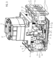
- Fig. 1 shows an exemplary embodiment of a switch 1 according to the invention.
- This has a switch housing 2 in which a number of individual switching chambers 3 are arranged.
- An actuating device 5 for the switch 1 is arranged on the top of the switch housing.
- This comprises a rotary positioning drive 57 in which, for example, a handle or the like for adjusting the rotary positioning drive can be used.
- the rotational movement of the rotary positioning drive 57 is converted into a linear adjustment of a bridge via a corresponding mechanism.
- this bridge On its underside 8 facing the individual switching chambers 3, this bridge has a contact surface; see also Figs. 3 to 5 .
- a corresponding plunger 61 is vertically adjusted and along with it a corresponding counter-contact element 9 in order to make contacts with switching contact elements 4 within each individual switching chamber 3.
- the individual switching chambers 3 are connected to each other and can consist of a single switch housing divided into chambers, wherein the chambers are closed off via a common base plate, or also in each case separately via a base plate individually closing off each chamber.
- connecting elements in the form of, for example, L-shaped push-on projections 49 are arranged as sliding arms 35 (see also Fig. 13 ). Of these L-shaped push-on projections 49, two are arranged one above the other with a latching projection 52 between them. These serve for connecting different switch housings 2 to each other or also for attaching further parts; see the following embodiments.
- actuating device 5 is arranged in a specific orientation, while in Fig. 2 the orientation is rotated by 180° exactly.
- the remaining parts of the switch housing as well as the individual switching chambers 3 are arranged in the same way in both exemplary embodiments according to Figs. 1 and 2 . Due to the different orientation of the actuating device 5 according to Figs. 1 and 2 , these two four-pole switches can also be combined in their assembly (in this regard, see Fig. 20 ).
- Fig. 3 shows a corresponding switch 1 according to Figs. 1 and 2 in a partially exploded view but without a corresponding switch housing 2.
- These adjust corresponding plungers 61 in the vertical direction along with corresponding counter-contact elements; see in particular the disconnected position 11 according to Fig. 3 , in which the counter-contact element 9 is separated from contact pins 17 as part of the switching contact elements 4.
- Each individual switching chamber 3 has a base plate 7 as well as two mutually opposing switching contact elements 4. According to the invention, such an individual switching chamber 3 is furthermore closed off by contact element covers 12.
- the corresponding base plate 7 is inserted from below into the individual switching chambers 3 and is fastened there for example by friction welding.
- the corresponding contact element covers 12 can be latched onto the switch housing 2 (in this regard, see also Fig. 6 ).
- a corresponding contact element cover 12 has a lateral insertion opening 15 for inserting cable connections or the like, which can then be fastened in each switching contact element 4 by means of a clamping screw 14.
- the corresponding cable connection is fixed by the clamping screw 14 in a receiving opening 16 by means of the corresponding contact pin 17 (in this regard, see also Fig. 10 ).
- the contact pins 17 are supported from below by corresponding bearing clips 24 of the base plate 7 so that, although they are rotatable, they are fixed in terms of longitudinal displacement.
- a gap cylinder 20 of the contact pin 17 is arranged between the base plate 7 and the receiving opening 16. This forms a puncture-proof gap 22 with a corresponding edge 21 of the receiving opening 16.
- each contact element cover 12 Via the lateral insertion openings 15 of each contact element cover 12, a corresponding cable or the like is inserted in the direction of the switching contact element 4 into each individual switching chamber 3.
- the plungers 61 are spring-loaded in the direction of the actuating device 5. Via cams of a corresponding cam element 6 (see Figs. 4 and 5 ), the corresponding plunger 61 can, via the bridge 81, be pressed down in the direction of the base plate 7 against the spring force. When the cam element 6 is rotated correspondingly, the spring application will be able to move the plunger 61 upwards until it comes into contact with the corresponding contact pin 17.
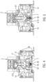
- Figs. 4 and 5 show a representation analogous to Fig. 3 for different positions of the plunger 61.
- the corresponding plunger 61 is deflected downwards against the spring action of a spring element 30, so that the corresponding counter-contact element 9 (see also Fig. 3 ) is arranged in its disconnected position 11 with regard to corresponding switching contact elements 4.
- the counter-contact element 9 is in its contact position 10 with the corresponding switching contact elements 4, so that an electrical connection is established between the two mutually opposing switching contact elements of the corresponding individual switching chamber 3.
- the switching contact elements 4 and in particular the terminal 66 can be arranged in two different orientations in the corresponding individual switching chamber. While in Fig. 4 the corresponding clamping screw 14 is accessible from above and the contact element cover 12 is also correspondingly arranged, in Fig. 5 an arrangement of the clamp 66 is rotated by 180°. As a result, the clamping screw 14 is accessible from below, i.e. from sides of the base plate 7, wherein the contact element cover 12 is also arranged in a manner rotated by 180°.
- Corresponding openings 60 are provided in the individual switching chambers 3 or also in the switch housing 2, for allowing access to the clamping screws 14.
- a corresponding lateral contact element cover 12 is shown enlarged and on its own. This has tabs 58 at the top and bottom ends for latching to the individual switching chamber 3 or the switch housing 2.
- the lateral insertion opening 15 is formed, via which a corresponding cable connection can be introduced in the direction of switching contact elements 4.
- a plug-in identification plate 80 for identification of the individual switching chamber can be arranged in the upper region of the contact element cover.
- the contact element cover 12 can likewise be arranged in two orientations depending on the arrangement of the switching contact elements 4.
- the contact element cover 12 On its side projecting inwardly in the direction of the individual switching chamber 3, the contact element cover 12 has a supporting surface 13 which laterally supports a clamping screw 14 (see also Fig. 3 ), wherein at the same time the supporting surface 13 can have an inwardly projecting projection for captively holding the clamping screw 14 (see also the other embodiments).
- the clamping screw 14 is held by the corresponding projection of the support surface 13 and is captively arranged in the individual switching chamber 3.
- Fig. 7 shows a perspective view of the underside of a corresponding switch 1.
- the switching contact elements 4 are partially cut, with the corresponding clamping screws 14 facing downwards toward the bottom plates 7.
- the underside of each individual switching chamber 3 is closed off by the base plate 7. This results in an explosion-proof arrangement of the switching contact elements 4 in the switch 1.
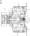
- a vertical section through the switch 1 is shown.
- the plungers 61 are arranged by a corresponding arrangement of the cam element 6 in such a way that the counter-contact element 9 is in electrical contact with the switch contact elements 4 on both sides.
- the corresponding plunger 61 or the counter-contact element 9 is arranged in its contact position 10.
- the base plate 7 has a corresponding receptacle for the spring element 30 (see spring receiving opening 29).
- the switching contact elements 4 are arranged in such a way that the clamping screw 14 is accessible from below.
- corresponding openings 67 and 68 are formed above and below the corresponding switching contact element 4. Via these, the clamping screws 14 are accessible from above or below, depending on their arrangement.
- FIG. 9 shows such a different orientation of the switching contact elements 4.
- the clamping screws 14 are accessible from above, i.e. from the actuating device 5.
- each switching contact element 4 has a contact pin 17. This extends from its insertion end 18 to its contact end 19. The contact end 19 serves to contact the counter-contact element 9 (see also Figure 8 ).
- a puncture-proof gap 22 is formed between the corresponding opening edge 21 of the receiving opening 16 and the gap cylinder 20.
- the corresponding spring element 30 is compressed downwardly in the direction of the base plate 7.
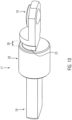
- the contact pin 17 is shown enlarged and without any other parts.
- the corresponding insertion end 18 is formed essentially by a rectangular portion of the contact pin 17.
- the gap cylinder 20 is attached to this insertion end 18.
- the contact pin 17 On the side of the gap cylinder 20 opposite the insertion end 18, the contact pin 17 has an approximately semicircular bearing groove 23. This serves for the rotatable, linearly non-displaceable mounting of the contact pin 17 with corresponding bearing clips 24 of the base plate 7 (see also Figs. 11 and 12 ).
- the bearing groove 23 has a corresponding bearing groove width 28 which corresponds essentially to a material thickness 27 (see Fig. 11 ) of a bearing clip 24.
- the contact pin 17 has its contact end 19 next to the bearing groove 23. This serves for contacting the counter-contact element in its contact position 10 (see also the preceding embodiments).
- the base plate 7 is shown on its own. This has, in an approximately central position, the spring receiving opening 29, which comprises a spring receptacle 59 for mounting a lower end of the spring element 30 (in this regard, see Figs. 8 and 9 ).
- the bearing clips 24 are arranged on both sides adjacent to the spring receiving opening 29. These extend upwardly in the direction of the contact pin and have approximately semicircular contact pin receptacles 26 at their free ends 25. These serve for receiving the corresponding bearing groove 23 (see also Fig. 10 ). The engagement of the contact pin receptacle 26 and the bearing groove 23 allows the contact pins 17 to be rotatable but non-displaceable in the longitudinal direction.
- the switch 1 as shown so far has, for example, four individual switching chambers 3. This number of individual switching chambers 3 is only by way of example, wherein fewer or more individual switching chambers 3 can be arranged in a corresponding switch housing 2 of the switch 1.
- auxiliary switching chamber 31 as an independent part or also in interaction with the switch 1.
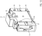
- Fig. 13 in a lateral perspective view.
- the auxiliary switching chamber 31 can be releasably secured to one side of a corresponding switch housing 2 of the ganged cam switch 1.
- the auxiliary switching chamber 31 has a sliding-type actuating element 34 by means of which, in the interior, a corresponding plunger is vertically movable in the switch in a manner analogous to the previous embodiments.
- the auxiliary switching chamber 31 has corresponding switching contact elements 4.
- the contact element covers 12 are formed to cover two switching contact elements 4 arranged side by side, so that in the exemplary embodiment of the auxiliary switching chamber 31 according to Fig. 13 , two pairs of switching contact elements 4 are arranged therein (see also the following embodiments).
- the latter has at least on one side corresponding fastening elements (see L-shaped sliding arms 35 and locking projection 37).
- the sliding arms 35 form push-on projections 49 or push-on sections 36 (see also the remaining embodiments) onto which a corresponding push-on arm 50 can be pushed and then fastened by latching with the latching projection 37, 52 by means of a corresponding latching arm 53.
- auxiliary switching chamber 31 is depicted without an outer housing and in an exploded view.
- the sliding-type actuating element 34 is arranged such that the counter-contact element 9 is in electrical contact with two mutually opposing switching contact elements 4.
- the construction of the switching contact elements 4 is analogous to that of the switch 1 described above. It can also be seen that a total of two switching contact elements 4 are arranged on each side of the auxiliary switching chamber 31 and are held by the contact element cover 12 as a side wall 38 of the auxiliary switching chamber 31. Differently oriented arrangements of the switching contact elements 4 are also possible in the auxiliary switching chamber 31 (see the left-hand side in Fig. 14 and the right-hand side in Fig. 14 ).
- the switching contact elements 4 are oriented in such a way that the corresponding clamping screw 14 is accessible from above in the direction of a lid 63 of the auxiliary switching chamber 31.
- the switching contact elements 4 are held in an arrangement rotated by 180°, in which the clamping screws 14 are accessible from below, i.e. from a base plate 39.
- the base plate 39 of the auxiliary switching chamber 31 is also connected to the remaining parts of the auxiliary switching chamber 31 by, for example, friction welding.
- a corresponding housing of the auxiliary switching chamber 31 is shown in Fig. 13 .
- the corresponding contact element covers 12 can be latched to the remaining housing of the auxiliary switching chamber 31 (see the corresponding latching projections 52 at the bottom and at the top of the side walls 38).
- Holding arms 62 are provided on an inner side of each side wall 38, which can also be arranged analogously in the case of the contact element cover 12 of the switch 1. These serve for different height arrangements of the various switching contact elements and for captively holding the corresponding clamping screws 14.
- the base plate 39 likewise has bearing clips 40 which, however, are formed according to Fig. 14 for receiving two contact pins in order to be able to arrange corresponding contact pairs 32, 33.
- the counter-contact element 9 is arranged with the lower contact pair 33, upper contact pair 32 or in a central position between the contact pairs 32, 33.
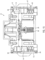
- Fig. 15 shows a representation analogous to Fig. 14 in which the side walls 38 are latched (see the tabs or latching projections 58). In this case, only the upper contact pair 32 according to Fig. 14 is visible, while the lower contact pair 33 is covered by corresponding partition walls 43 (see also Fig. 16 ). This serves for explosion protection.
- the corresponding switching contact elements 4 are arranged in different orientations to the left and right (see in particular the orientation of the clamping screws 14).
- the corresponding holding arms 62 serve for captively retaining the clamping screw 14 in that they have a retaining projection 44 (see also Figure 18 ) which in particular at least partially overlaps a screw head 48. That is, although the clamping screws can be released for the purpose of inserting a cable connection for connection to the switching contact elements 4, they are only released until there is corresponding contact with the retaining projection 44.
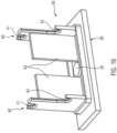
- the corresponding base plate 39 of the auxiliary switching chamber 31 is shown in Fig. 16 .
- This is constructed similarly to the base plate 7 of the individual switching chambers 3.
- the bearing clips 40 have two contact pin receptacles 41, 42, by means of which a part of the corresponding contact pairs 32, 33 or associated contact pins 17 is held in an analogous way to the previous embodiments.
- the contact pin receptacles 41, 42 are arranged at different heights, wherein partition walls 43 are arranged between the bearing clips 40 and also between the contact pin receptacles 41, 42. These extend approximately from the bearing clips 40 to the spring receiving opening 29. Analogously to the spring-receiving opening in the individual switching chambers, this serves for supporting a spring element 30 acting on the plunger 61 by spring-loading.
- bearing groove 24 and bearing clip 25 in connection with the individual switching chambers also apply to the bearing clips 40 and contact pin receptacles 41, 42 in the case of the auxiliary switching chamber 31.
- Fig. 17 shows a corresponding contact pin 17 of the auxiliary switching chamber 31. This is constructed similarly to the contact pin 17 of the individual switching chamber 3.
- a gap cylinder 20 with a laterally adjacent bearing groove 23 is provided approximately centrally.
- the contact end 19 then adjoins the bearing groove 23 and the insertion end 18 adjoins the gap cylinder 20 at the other end.
- the insertion end 18 does not have a square cross-section throughout, but also at least two portions with a reduced cross-section.
- Fig. 18 shows a perspective side view of an auxiliary switching chamber 31.
- the arrangement of the switching contact elements 4 is shown.
- these are both arranged with the same orientation but at a height offset from each other. That is, the corresponding clamping screws 45 are both accessible from below, in other words, from the base plate 39.
- the corresponding insertion end 18 of the contact pins 17 is visible in the corresponding receiving opening 16.
- the clamping screws 45 are held at their screw head 48 by the retaining projection 44 as a corresponding edge projection, wherein this edge projection 46 is supplemented by an edge projection 47 (see Figure 15 and side wall 38).
- switches or also switches and auxiliary switching chambers can be connected to each other. This can be effected directly by means of corresponding auxiliary means (see the preceding embodiments) or via a coupling frame part 54, which is visible in Fig. 19 in a perspective side view.
- the coupling frame part 54 has corresponding connecting elements along its side edges.
- An upper connecting element is, for example, a push-on arm 50, which projects beyond the coupling frame part 54 on both sides.
- a lower connecting element is another push-on arm 50, which is formed analogously to the upper push-on arm.
- a latching arm 53 is arranged in the height direction 51 between the two push-on arms 50.
- the push-on arms 50 are used to slide onto the L-shaped sliding arms 35 or L-shaped push-on projections 49 (see the following and preceding embodiments).
- one side of the coupling frame part 54 is, for example, assigned to one side of the switch housing 2 of a switch 1 and fastened there, while the other side of the coupling frame part 54 serves to fasten a further switch housing or also an auxiliary switching chamber 31.
- the coupling frame part 54 can also be used for connecting two auxiliary switching chambers 31.
- each switch 1 has a corresponding switch housing and a number of individual switching chambers 3.
- the coupling frame part 54 is arranged between the two switch housings 2.
- a corresponding actuating device 5 Arranged above the switch housings 2 in each switch 1 is a corresponding actuating device 5, on which a collective actuating device 64 for simultaneous and analog actuation of the actuating devices 5 is arranged.
- Each switch 1 is structured as already explained above. It can also be seen in Fig. 20 that, on the free side faces of the switch housing 2, corresponding devices are formed for the attachment of a further switch or also of an auxiliary switching chamber 31; see push-on sections 36 in the form of L-shaped push-on projections 49. In addition, a latching projection 52 is arranged correspondingly between them.
- the orientations of the actuating devices 5 are here rotated by 180°.
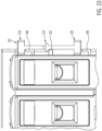
- a corresponding coupling frame part 54 is arranged on one side of a switch 1. This is in its latched position, since the latching arm 53 engages beneath the latching projection 52.
- an auxiliary switching chamber 31 is directly connected to a side face of a switch 1, wherein the corresponding connecting elements are used here as well (see push-on projection, push-on arm, latching projection and latching arm).
- a coupling frame part 54 is arranged between the auxiliary switching chamber 31 and the ganged cam switch 1 in order, for example, to increase the distance between the two.
- a coupling frame part 54 is arranged in its as yet unconnected position. That is, the L-shaped push-on projections 49 are still exposed and the latching arm 53 is not yet engaging beneath the latching projection 52.
- the coupling frame part 54 is then in its fastened state, and in particular the latching arm 53 engages beneath the latching projection 52.
- the side of the coupling frame part 54 shown on the right in Fig. 24 can then serve for attaching a further switch housing 2 of a switch 1 (see Fig. 20 ) or for holding an auxiliary switching chamber 31.
- Fig. 25 shows a switch 1 according to the preceding exemplary embodiments, wherein this switch has a partition plate 55 on one side, on the other side of which an auxiliary switching chamber 31 is arranged.
- This partition plate serves essentially as an Ex-i partition plate between switch 1 and auxiliary switching chamber 31.
- Fig. 26 shows the partition plate 55 without a corresponding auxiliary switching chamber 31 as shown in Fig. 25 .
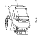
- An open inner contour 56 which does not cover the corresponding connecting elements on the switch housing 2 of the switch 1 can be seen, so that (see Fig. 27 ) an auxiliary switching chamber 31 can be attached in the already described manner via L-shaped push-on projections, push-on arms, latching projection and latching arm.
- the corresponding partition plate 55 projects at least laterally and upwardly beyond the auxiliary switching chamber 31 and separates it from the switch housing 2 of the switch 1.
- Fig. 28 shows a perspective view of a latching device 65, which is adjustably mounted on the base plate and/or on the switch housing. The corresponding latching direction is also visible, for example, in Fig. 3 .
- the latching device 65 is essentially formed as a snap-on latch, which is displaceably mounted relative to, for example, the base plate 7 (see again Fig. 3 ) by means of lateral guide projections 77.
- the latching device 65 has an upper side 69 and a lower side 70, wherein the upper side 69 is associated with the base plate 7. At one end, the latching device has a latching end 71 with a latching nose 78. This serves to fasten the switch to a DIN rail or the like.
- stops 72 are arranged on the upper side 69, which limit an engagement of the latching nose 78 relative to a DIN rail (not shown).
- the locking device has a number of openings, one opening 73 of which is in each case assigned to a corresponding opening 67, 68 of an individual switching chamber 3. That is, even when a snap-on latch is present, the corresponding clamping screws are accessible via opening 73 and openings 67, 68.
- the snap-on latch has at least one further opening 74 adjacent its end opposite the latching nose 78. This opening 74 serves in particular for the insertion of a tool or the like, in order to pull the snap-on latch out of engagement with the DIN rail.
- Two spring elements 75, 76 are mounted at a distance from each other in the snap-on latch 65 (see also Fig. 30 ). These (see also Fig. 29 ) are supported, for example, on a contact element cover 12 or within the switch housing 2, in order to push the snap-on latch in the direction of the DIN rail. A corresponding engagement of the snap-on latch is limited by abutment of the stops 72 in particular against the base plate 7. This corresponding position is shown in Figure 29 . That is, in Fig. 29 the snap-on latch is arranged in its engaged position with a DIN rail (not shown). By means of the opening 74, the snap-on latch can be displaced to the left from the position shown in Fig.
- At least one latching hook 82 projects from in particular the upper side 69 of the latching device 65.
- this disconnected position relative to an outer side 83 is defined by the at least one latching hook.
- the latching hook can likewise be formed in pairs, in particular on both sides of the further opening 74 on the upper side. The latching device is therefore automatically held open in the disconnected position.
- the switch housing can thereby be positioned in a simple manner relative to the DIN rail.
- latching between latching hook and switch housing 2 or contact element cover 12 can be released by slight pressure on the latching device, in particular downwardly or at least obliquely downwardly.
- the snap-on position is then automatically assumed by the spring elements.
- Fig. 30 shows the corresponding stops 79 of the switch, on which the spring elements 75 and 76 are supported, leaving the opening 73 free.
- a switch with a number of individual chambers for each contact results.
- the switch is suitable for housing installation or front-panel mounting due to the different orientation possibilities of the corresponding switching contact elements. That is, it can be arranged in different positions in a simple manner without complicated measures, wherein the switch is of modular design (see the individual switching chambers and the switching contact elements) and these can be oriented differently depending on the mounting of the switch.
- the corresponding switching contact elements are not glued or potted, but are arranged in a manner detachable and differently orientable in the particular individual switching chamber 3.
- the corresponding base plate is fastened from below to each individual switching chamber and in particular is welded there.
- the corresponding contact element covers can also be used easily for each individual switching chamber. No further components are necessary for the different orientations, in particular the switching contact elements, but individual switching chambers and also contact element covers are provided for both orientations.
- the auxiliary switching chamber is a separate component which can be used both independently and together with the switch according to the invention.
- the auxiliary switching chamber has two pairs of switching contact elements which essentially correspond to the structure of the individual switching chambers of the switch; see the different orientations of the switching contact elements, the different orientation of the side wall or contact element cover.
- the switching contact elements and in particular their contact pins are rotatable, they are held in a manner longitudinally displaceable for each switching contact element.
Landscapes
- Physics & Mathematics (AREA)
- Electromagnetism (AREA)
- Engineering & Computer Science (AREA)
- Manufacturing & Machinery (AREA)
- Switch Cases, Indication, And Locking (AREA)
Description
- The invention relates to a switch, usually an electrical switch, which serves, for example, as a main switch, in particular as a switch disconnector, for manually switching a number of electrical contacts. The invention relates to a switch according to the preamble of claim 1. In a specific design, the switch is formed as a rotary switch, with a conversion of a rotational movement of the rotary switch into a linear movement. A cam element of the rotary switch carries a series of cams which, depending on the adjustment of the cam element, move counter-contact elements between the contact position and the disconnected position.
-
DE 44 40 554 B4 describes a switch which has a base plate on which at least one cam disk, which is coupled to a switching shaft, is rotatably mounted for one switching element in each case. Between each cam disk and the actuating shaft, a driver disk is connected; this can be coupled in different positions to the cam disk in a rotationally fixed manner. A switch according to the preamble of claim 1 is known fromUS 4 713 498 A . Further switches are known fromFR 2 622 734 A1 FR 2 949 017 A3 - A ganged cam switch with several individual switching chambers arranged side by side is known, for example, from
DE 10 2008 004 747 B3 . Each individual switching chamber contains at least two switching contact elements, which can be electrically connected to each other via corresponding counter-contact elements. The ganged cam switch has a switch housing, in which a number of such modular individual switching chambers, which can be arranged in particular side by side in the switching housing, are contained. Above the individual switching chambers, the switch housing is closed off by an actuating device for adjusting the corresponding cam element. Through a corresponding adjustment of the cam element, an electrical connection can be established selectively between the switching contacts of an individual switching chamber via the corresponding counter-contact elements. - In the case of the known switches, it has been found to be disadvantageous that a corresponding expandability of the switch and a variable alignment and arrangement of the switch is not possible at all or is possible only with considerable effort.
- The object of the invention is therefore to improve a switch of the type mentioned at the outset in such a way that an extension or a modified arrangement and in particular an adaptation to the housing installation or front-panel mounting is possible in a simple manner. At the same time, it should also be possible for all explosion protection requirements to be met.
- This object is achieved by the features of claim 1. The invention is characterized in particular in that the switching contact elements can be arranged within the switch housing in at least two different orientations and in that the cam element of the actuating device can be arranged differently depending on the orientation of the switching contact elements. These options make it possible to adapt to a housing or ceiling installation in a simple manner. For example, due to the different arrangability of the cam element, the actuating device can be converted for left-hand or right-hand operation. At the same time, the arrangement of the switching contact elements (also called terminals) can be changed easily, so that, as a whole, a switch with particular variability and adaptability to installation results. Of course, the switching contact elements of the individual switching chambers can also be oriented in different ways.
- After a corresponding installation of the individual switching chambers with elements located therein, in order to close off the switch housing securely, including with regard to explosion protection, each individual switching chamber can have a base plate connected in particular to the switch housing. After insertion of the individual switching chambers, this is fitted with corresponding internal parts for the purpose of closing off the individual switching chambers. A common base plate for a number of individual switching chambers is likewise conceivable. The connection can be made gas-tight and in particular welded to the corresponding switch housing.
- In order to be able to connect the various switching contact elements to each other in a simple manner, the actuating device can have a rotary positioning drive which carries out a linear adjustment of the cam element, wherein the cam element has on a bottom side facing the switching contact elements a corresponding number of cams for moving counter-contact elements between the contact position and the disconnected position. In a corresponding disconnected position of the cam element, for example, the switching contact elements of an individual switching chamber are not electrically connected to each other, wherein, however, this can be realized for one or more of the other individual switching chambers. In this way, different individual switching chambers can be electrically conductively connected by correspondingly adjusting the cam element by means of the rotary positioning drive.
- The structure and the variability of the switch is further simplified or elevated when each individual switching chamber has a contact element cover as a side wall, which can be connected to the individual switching chambers depending on the orientation of the switching contact elements. That is, the contact element cover can also be oriented differently depending on the orientation of the switching contact element, so that, for example, the corresponding orientation of the switching contact element can be recognized by the orientation of the contact element cover.
- In order to simplify the design of the switch, it proves advantageous if all of the individual switching chambers are essentially of identical design and the contact element covers of all individual switching chambers are also of identical design.
- For example, in order to connect such a contact element cover to the individual switching chamber in a simple manner, the contact element cover can be latched to the individual switching chamber.
- The contact element cover can simultaneously serve for inserting a cable connection or the like from the outside in order to make connection with the switching contact element. In addition, it may prove advantageous if the contact element cover has a rounded supporting surface for a clamping screw of a contact element. The clamping screw serves to fix an electrical supply line or cable connection in the switching contact element and can be reached by an appropriate tool from outside the switch housing. Furthermore, it is advantageous if the clamping screws are also accessible from different orientations depending on the orientation of the switching contact elements.
- To enable the introduction of a corresponding electrical line or a plug-in contact, the contact element cover can have a lateral insertion opening. This can additionally be used for arranging a plug-in identification plate for identifying the individual switching chamber.
- The contact element can have a greater variability if it takes the form of a contact pin which, for example, is designed differently depending on what is required. In order to be able to arrange the contact pin as part of the contact element in a simple manner, the contact element can have a terminal with a receiving opening for an insertion end of the contact pin, which at its contact end opposite the insertion end is in contact with the counter-contact element in its contact position . In this case, the contact pin can, for example, be rectangular or the like at its insertion end, thereby enabling an anti-rotation function with respect to a correspondingly shaped receiving opening. In order to be able to provide a corresponding explosion protection via the contact pin, it can furthermore prove advantageous in this connection for the contact pin to have a gap cylinder in an approximately central position, between which and an edge of the receiving opening a flameproof gap is formed. That is, the corresponding diameter of the gap cylinder is, as a rule, the same as the diameter of the receiving opening, so that the gap cylinder rests around the receiving opening at the corresponding edge and a gap is formed there. Thereby, the gap has a length and gap width which delivers the desired explosion protection.
- In order to be able to support the contact pin also in the direction of the terminal, it is conceivable that a bearing groove for longitudinally fixing the contact pin is formed between the gap cylinder and the contact end of the contact pin. This bearing groove accommodates a corresponding further part of the bearing housing or the individual switching chamber, so that, although the corresponding engagement permits a rotation of the contact pin, it is nevertheless fixed in the longitudinal direction.
- In this connection, it can prove advantageous if the base plate has, in particular, two bearing clips projecting in the direction of the contact pin and engaging with their free ends in the bearing groove.
- In order to improve engagement in this situation, the free end of the contact pin can take the form of an approximately U-shaped contact pin receptacle. This contact pin receptacle then engages in the corresponding bearing groove.
- In order to enable the most precise fixing possible in the longitudinal direction of the contact pin, a material thickness of the bearing clip or of the corresponding contact pin receptacle can correspond to a bearing groove width.
- The base plate can optionally also be used to support the counter-contact elements. This can be effected, for example, by the base plate having in an approximately central position a spring receiving opening for a spring element acting on the counter-contact element. The spring element is inserted, for example, with one end into this spring receiving opening, and with the other end supports a corresponding counter-contact element. It should be noted that such a counter-contact element can have, for example, two spaced-apart contacts which are in contact with the two switching contact elements of an individual switching chamber correspondingly in the contact position of the counter-contact element. This establishes the electrical connection between the two switching contact elements through the individual switching chamber.
- A corresponding switch with a plurality of individual switching chambers has been described above. It is now possible to use even a plurality of these switches as main switches and optionally also to connect them to each other via corresponding side walls facing each other. It is also possible to use such a switch together with an auxiliary switching chamber which, for example, is attached to a side wall of the switch or which at least together with the switch is mounted on a rail or another location. Such an auxiliary switching chamber is a single part which can also be used without a switch. It is also true of the auxiliary switching chamber that it can be used both for housing installation and front-panel mounting. However, more than two switching contact elements are, as a rule, provided in the auxiliary switching chamber, i.e., for example, two or even more pairs of corresponding switching contact elements. The auxiliary switching chamber is of a similar design to an individual switching chamber of the aforementioned switch. However, if a plurality of contact pairs is used in an auxiliary switching chamber, they will be separated by a corresponding wall in order, for example, to realize explosion protection class Ex-e. The auxiliary switching chamber may be made of a corresponding plastic material or the like.
- In particular, a corresponding auxiliary switching chamber has a side wall which can in particular be arranged laterally on the switch housing of the switch, the auxiliary switching chamber having at least two contact pairs of corresponding switching contact elements.
- The auxiliary switching chamber can be actuated in a different way, since a corresponding coupling to the actuating device of the switch is not necessarily provided. For this purpose, the auxiliary switching chamber can have an outwardly projecting sliding-type actuating element. This can be displaced in the longitudinal direction against a corresponding spring force in order to, in this way, bring a corresponding counter-contact element into contact in each case with a pair of switching contact elements. That is, three different positions are, as a rule, conceivable with the auxiliary switching chamber, wherein in a first position no contact is made with the switching contact elements, while in the other two positions at least one contact is made with the respective pair of associated switching contact elements. The corresponding adjustment is effected here by means of the sliding-type actuating element. This can be connected to a plunger, on which the counter-contact element is embodied in the form of two contact elements projecting radially outwardly.
- With regard to the auxiliary switching chamber, it should furthermore be noted that this has, for example, in particular two pairs of essentially L-shaped sliding arms which can be pushed onto push-on sections projecting laterally from the switch housing of the ganged cam switch and can be fixed in the pushed-on position by means of a latching projection. It is also conceivable for the arrangement of sliding arms and push-on sections to be effected in the reverse manner. In addition, corresponding devices can also be arranged between switch housings, for example, in order to connect the switch housings of a switch to each other.
- The auxiliary switching chamber can realize the corresponding switching contact elements in a manner similar to that in the individual switching chambers. That is, such an auxiliary switching chamber can have on opposite sides two switching contact elements with corresponding contact pins. These have already been described in connection with the aforementioned individual switching chamber of the switch. The corresponding design of these elements also applies to the auxiliary switching chamber, and also conversely the further embodiments relating to the auxiliary switching chamber are transferable to the individual switching chambers of the switch.
- That is, the auxiliary switching chamber can also have a base plate with bearing clips, wherein, in this connection, however, each bearing clip has two U-shaped contact pin receptacles, since the auxiliary switching chamber described has, for example, two pairs of switching contact elements with corresponding contact pins.
- It has already been pointed out that, in order to provide Ex-e explosion protection, the two pairs of contacts should be separated, wherein, in this connection, this can be realized in that partition walls converging on each other are formed between the bearing clips. These separate the corresponding contact pairs from each other and also the two U-shaped contact pin receptacles.
- Both the auxiliary switching chambers and the individual switching chambers are connected to their respective base plate. The connection is preferably of a gas-tight design, wherein this is effected, for example, by adhesive bonding and welding, in particular friction welding. In order not to lose the corresponding clamping screws in the switching contact elements, it may prove helpful if the side walls of the auxiliary switching chamber or individual switching chambers and their corresponding side walls have retaining projections in the region of the switching contact elements for holding such clamping screws of the switching contact elements. This makes it possible to screw the clamping screws to the switching contact elements in order to fasten the corresponding supply lines while at the same time preventing excessive loosening of the clamping screws and possible loss of the clamping screws.
- In the simplest case, it is possible for the corresponding retaining projections to take the form of concavely curved edge projections which project inwardly in the direction of the screw head of the clamping screw and which partially overlap the screw head. That is, the clamping screw is unscrewed from the corresponding switching contact element until this contact between the edge projections and the screw head occurs.
- It has already been pointed out that not only the switch housing[s], but also a switch housing and an auxiliary switching chamber, can be connected to each other. As a rule, this can be done in a favorable manner by means of essentially L-shaped push-on projections being formed, which projections project from at least one side wall and onto which the push-on arms, which are shaped in a substantially complementary manner, can be pushed. As a result, switch housings can be connected to each other via side walls facing each other without the aid of further tools, wherein this is likewise the case for a connection between the switch housing and the auxiliary switching chamber.
- In this connection, in order to improve the connection between the parts, for example, two push-on projections or push-on arms can be arranged at a distance from each other in the height direction. This results in a double connection via an engagement in each case of the push-on arm and the push-on projection.
- It has likewise already been pointed out that latching can take place simultaneously in the pushed-on position. This can be realized, for example, in that a latching projection is formed between the push-on projections and a latching arm is formed between the push-on arms, or vice versa.
- There is also the possibility that the corresponding side walls of the switch housing and auxiliary switch chamber are of identical design, so that the connection cannot take place directly between them. Instead, a coupling frame part can be arranged between two adjacent switch housings and/or a switch housing and auxiliary switch chamber, which coupling frame part has corresponding push-on arms and/or latching arms on both sides. That is, a connection to, on the one hand, the switch housing and, on the other hand, a connection to an adjacent switch housing or to the auxiliary switching chamber takes place via this coupling frame part. In this connection, the corresponding devices of the switch housing and the auxiliary switching chamber can then be of the same design; i.e., they can be formed only from push-on projections and latching projections. The push-on arms or latching arms are then arranged on both sides of the coupling frame part.
- There is the possibility that such a coupling frame part has two sides and corresponding connecting devices are provided on each side. It is likewise conceivable for the push-on arms or latching arms to extend essentially through the coupling frame part, so that push-on arms and latching arms are formed in one piece.
- In order to prevent the screwing of the different parts, the coupling frame part is used, for example. If, in addition to the coupling frame part, there is possibly still a corresponding explosion protection between the parts, a partition plate can then be used which can be arranged, for example, between switch housings and/or switch housing and auxiliary contact chamber. This partition plate has an open inner contour, by means of which a connection between the switch housings and/or switch housing and auxiliary switching chamber is possible in the manner already described above. That is, the corresponding connecting means between switch housing and auxiliary switching chamber are not covered by the partition plate, but are instead exposed due to its inner contour.
- The partition plate can be formed as an Ex-i partition and extend, in particular, beyond the contour of the switch housing and/or the auxiliary contact chamber at least laterally and/or upwardly.
- A corresponding switch may include different numbers of individual switching chambers. The number of individual switching chambers depends on the size of the switch housing. For example, two, three, four or even more individual switching chambers can be arranged in a switch housing of a corresponding size. Correspondingly, the cam element is also formed to actuate the number of switching contact elements. It has already been pointed out that the actuating device can be oriented differently for left-handed and right-handed operation, while the other components of the switch housing have an identical design to the individual switching chambers. Furthermore, in each individual switching chamber, the corresponding switching contact elements can be arranged with a rotated orientation, in particular rotated by 180°. This makes it possible to adapt to housing installation or front-panel mounting in a simple manner. In addition, a simple coupling of, in particular, four-pole switches can be effected by a corresponding rotation of the actuating device. The actuating device has a fixed length and in the case of a three-pole switch covers the entire switch housing. In the case of a four-pole switch, the actuating device is mounted in an edge-locking manner, so that an individual switching chamber is not covered by the actuating element essentially on one side. If two four-pole switches are then coupled, an actuating device is rotated by 180°, so that both will be arranged on the associated sides of the adjacent switches in an edge-locking manner.
- Essentially, the same switch is always used, but only with different orientations of its components. After corresponding assembly of the switch housing, this will be configured for the particular realization of the desired ignition protection class; see, for example, the welding of the base plate to each individual switching chamber or in the switch housing.
- A corresponding flameproof gap is also realized in the switch according to the invention or in the corresponding auxiliary switching chamber; see the interaction of the gap cylinder and the receiving opening. As a rule, according to the invention no potting or gluing is carried out. A corresponding sealing of the switching chamber is effected by attaching the corresponding base plate, wherein welding and in particular friction welding is carried out in order to fasten the base plate. This applies both to the switch housing with the individual switching chambers and to the auxiliary switching chamber. The auxiliary switching chamber differs only in that, as a rule, at least two contact pairs are provided and the counter-contact element correspondingly makes a conductive connection with one of these pairs or separates both contact pairs from each other.
- The invention also relates to corresponding devices for arranging the auxiliary switching chamber on the switch housing or also on switch housings. Of course, the corresponding parts, such as the switch, auxiliary switching chamber and partition plate or coupling frame part, can also be used independently of each other and can be used not only in combination with each other. In the following, advantageous exemplary embodiments of the invention are explained in more detail with reference to the figures appended in the drawing.
- Shown are:
- Fig. 1
- a perspective oblique view of a switch according to the invention having four individual switching chambers;
- Fig. 2
- a view analogous to
Fig. 1 with a 180° rotated arrangement of an actuating device; - Fig. 3
- a switch according to
Fig. 1 without a switch housing; - Figs. 4 and 5
- a sectional view of the switch according to the invention with differently oriented switching contact elements;
- Fig. 6
- a perspective side view of a side wall of an individual switching chamber;
- Fig. 7
- a perspective view obliquely from below of a switch according to the present invention with a base plate;
- Fig. 8
- a sectional view of a switch with counter-contact element in the contact position;
- Fig. 9
- a sectional view analogous to
Fig. 8 with counter-contact element in the disconnected position; - Fig. 10
- a side perspective view of a contact pin;
- Fig. 11
- a perspective side view of a base plate;
- Fig. 12
- a side sectional view of the bottom plate according to
Fig. 11 ; - Fig. 13
- a perspective side view of an auxiliary switching chamber;
- Fig. 14
- an exploded view without the outer housing of the auxiliary switching chamber according to
Fig. 13 ; - Fig. 15
- a side view in section of an auxiliary switching chamber according to
Fig. 13 ; - Fig. 16
- a perspective side view of a base plate of an auxiliary switching chamber;
- Fig. 17
- a perspective side view of a contact pin of an auxiliary switching chamber;
- Fig. 18
- a perspective side view of an auxiliary switching chamber with two side-by-side switching contact elements;
- Fig. 19
- a perspective side view of a coupling frame part;
- Fig. 20
- a switch with two switch housings and a coupling frame part between them;
- Fig. 21
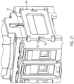
- a switch with a laterally arranged coupling frame part;
- Fig. 22
- a switch with laterally arranged auxiliary switching chamber;
- Fig. 23
- a side view of a switch with coupling frame part in the release position;
- Fig. 24
- a view analogous to
Fig. 23 with a coupling frame part in the connecting position; - Fig. 25
- a switch with a laterally arranged partition plate and auxiliary switching chamber;
- Fig. 26
- a side perspective view of a partition plate on a switch;
- Fig. 27
- a representation analogous to
Fig. 25 from another viewpoint; - Fig. 28
- a top perspective view of a latching device for attaching the switch to a DIN rail;
- Fig. 29
- a partially sectional illustration of the latching device in the assembled state; and
- Fig. 30
- a transparent representation of the latching device in plan view.
-
Fig. 1 shows an exemplary embodiment of a switch 1 according to the invention. This has a switch housing 2 in which a number ofindividual switching chambers 3 are arranged. Anactuating device 5 for the switch 1 is arranged on the top of the switch housing. This comprises arotary positioning drive 57 in which, for example, a handle or the like for adjusting the rotary positioning drive can be used. The rotational movement of therotary positioning drive 57 is converted into a linear adjustment of a bridge via a corresponding mechanism. On its underside 8 facing theindividual switching chambers 3, this bridge has a contact surface; see alsoFigs. 3 to 5 . Depending on the position of the bridge 81, a correspondingplunger 61 is vertically adjusted and along with it a correspondingcounter-contact element 9 in order to make contacts with switchingcontact elements 4 within eachindividual switching chamber 3. Theindividual switching chambers 3 are connected to each other and can consist of a single switch housing divided into chambers, wherein the chambers are closed off via a common base plate, or also in each case separately via a base plate individually closing off each chamber. On at least one corresponding side face of the switch housing 2, connecting elements in the form of, for example, L-shaped push-onprojections 49 are arranged as sliding arms 35 (see alsoFig. 13 ). Of these L-shaped push-onprojections 49, two are arranged one above the other with a latchingprojection 52 between them. These serve for connecting different switch housings 2 to each other or also for attaching further parts; see the following embodiments. - In
Fig. 1 , theactuating device 5 is arranged in a specific orientation, while inFig. 2 the orientation is rotated by 180° exactly. The remaining parts of the switch housing as well as theindividual switching chambers 3 are arranged in the same way in both exemplary embodiments according toFigs. 1 and 2 . Due to the different orientation of theactuating device 5 according toFigs. 1 and 2 , these two four-pole switches can also be combined in their assembly (in this regard, seeFig. 20 ). -
Fig. 3 shows a corresponding switch 1 according toFigs. 1 and 2 in a partially exploded view but without a corresponding switch housing 2. These adjust correspondingplungers 61 in the vertical direction along with corresponding counter-contact elements; see in particular the disconnected position 11 according toFig. 3 , in which thecounter-contact element 9 is separated from contact pins 17 as part of the switchingcontact elements 4. Eachindividual switching chamber 3 has abase plate 7 as well as two mutually opposing switchingcontact elements 4. According to the invention, such anindividual switching chamber 3 is furthermore closed off by contact element covers 12. Thecorresponding base plate 7 is inserted from below into theindividual switching chambers 3 and is fastened there for example by friction welding. The corresponding contact element covers 12 can be latched onto the switch housing 2 (in this regard, see alsoFig. 6 ). A correspondingcontact element cover 12 has alateral insertion opening 15 for inserting cable connections or the like, which can then be fastened in each switchingcontact element 4 by means of a clampingscrew 14. The corresponding cable connection is fixed by the clampingscrew 14 in a receivingopening 16 by means of the corresponding contact pin 17 (in this regard, see alsoFig. 10 ). The contact pins 17 are supported from below by corresponding bearing clips 24 of thebase plate 7 so that, although they are rotatable, they are fixed in terms of longitudinal displacement. Agap cylinder 20 of thecontact pin 17 is arranged between thebase plate 7 and the receivingopening 16. This forms a puncture-proof gap 22 with a corresponding edge 21 of the receivingopening 16. - Via the
lateral insertion openings 15 of eachcontact element cover 12, a corresponding cable or the like is inserted in the direction of theswitching contact element 4 into eachindividual switching chamber 3. - When the
counter-contact element 9 is in contact with the two mutually opposing switchingcontact elements 4, these will be connected electrically in order, for example, to provide a voltage to a corresponding device. - The
plungers 61 are spring-loaded in the direction of theactuating device 5. Via cams of a corresponding cam element 6 (seeFigs. 4 and 5 ), the correspondingplunger 61 can, via the bridge 81, be pressed down in the direction of thebase plate 7 against the spring force. When thecam element 6 is rotated correspondingly, the spring application will be able to move theplunger 61 upwards until it comes into contact with thecorresponding contact pin 17. -
Figs. 4 and 5 show a representation analogous toFig. 3 for different positions of theplunger 61. InFig. 4 , the correspondingplunger 61 is deflected downwards against the spring action of aspring element 30, so that the corresponding counter-contact element 9 (see alsoFig. 3 ) is arranged in its disconnected position 11 with regard to corresponding switchingcontact elements 4. On the other hand, inFig. 5 thecounter-contact element 9 is in its contact position 10 with the corresponding switchingcontact elements 4, so that an electrical connection is established between the two mutually opposing switching contact elements of the correspondingindividual switching chamber 3. - In the
Figs. 4 and 5 , it can be seen in particular that the switchingcontact elements 4 and in particular the terminal 66 can be arranged in two different orientations in the corresponding individual switching chamber. While inFig. 4 the corresponding clampingscrew 14 is accessible from above and thecontact element cover 12 is also correspondingly arranged, inFig. 5 an arrangement of the clamp 66 is rotated by 180°. As a result, the clampingscrew 14 is accessible from below, i.e. from sides of thebase plate 7, wherein thecontact element cover 12 is also arranged in a manner rotated by 180°. This is possible according to the invention without further changes to the ganged cam switch 1. Both a housing installation and a front-panel mounting can thereby be realized. Correspondingopenings 60 are provided in theindividual switching chambers 3 or also in the switch housing 2, for allowing access to the clamping screws 14. - In
Fig. 6 , a corresponding lateralcontact element cover 12 is shown enlarged and on its own. This hastabs 58 at the top and bottom ends for latching to theindividual switching chamber 3 or the switch housing 2. In the lower half of thecontact element cover 12, thelateral insertion opening 15 is formed, via which a corresponding cable connection can be introduced in the direction of switchingcontact elements 4. A plug-in identification plate 80 for identification of the individual switching chamber can be arranged in the upper region of the contact element cover. - As described in connection with
Figs. 4 and 5 , thecontact element cover 12 can likewise be arranged in two orientations depending on the arrangement of the switchingcontact elements 4. On its side projecting inwardly in the direction of theindividual switching chamber 3, thecontact element cover 12 has a supportingsurface 13 which laterally supports a clamping screw 14 (see alsoFig. 3 ), wherein at the same time the supportingsurface 13 can have an inwardly projecting projection for captively holding the clamping screw 14 (see also the other embodiments). In other words, the clampingscrew 14 is held by the corresponding projection of thesupport surface 13 and is captively arranged in theindividual switching chamber 3. -
Fig. 7 shows a perspective view of the underside of a corresponding switch 1. In this case, the switchingcontact elements 4 are partially cut, with the corresponding clamping screws 14 facing downwards toward thebottom plates 7. This applies analogously to both sides of the correspondingindividual switching chambers 3. The underside of eachindividual switching chamber 3 is closed off by thebase plate 7. This results in an explosion-proof arrangement of the switchingcontact elements 4 in the switch 1. - In
Fig. 8 , a vertical section through the switch 1 is shown. In this representation, theplungers 61 are arranged by a corresponding arrangement of thecam element 6 in such a way that thecounter-contact element 9 is in electrical contact with theswitch contact elements 4 on both sides. In other words, the correspondingplunger 61 or thecounter-contact element 9 is arranged in its contact position 10. Furthermore, it can be seen inFig. 8 that thebase plate 7 has a corresponding receptacle for the spring element 30 (see spring receiving opening 29). According toFig. 8 , the switchingcontact elements 4 are arranged in such a way that the clampingscrew 14 is accessible from below. Furthermore, it can be seen inFig. 8 that corresponding openings 67 and 68 are formed above and below the correspondingswitching contact element 4. Via these, the clamping screws 14 are accessible from above or below, depending on their arrangement. - As already explained above, an arrangement rotated by 180° of the switching
contact elements 4 is possible.Fig. 9 shows such a different orientation of the switchingcontact elements 4. In this case, the clamping screws 14 are accessible from above, i.e. from theactuating device 5. In particular, it can also be seen inFig. 9 that each switchingcontact element 4 has acontact pin 17. This extends from itsinsertion end 18 to itscontact end 19. Thecontact end 19 serves to contact the counter-contact element 9 (see alsoFigure 8 ). A puncture-proof gap 22 is formed between the corresponding opening edge 21 of the receivingopening 16 and thegap cylinder 20. In the arrangement of theplunger 61 according toFig. 9 , thecorresponding spring element 30 is compressed downwardly in the direction of thebase plate 7. - In
Fig. 10 , thecontact pin 17 is shown enlarged and without any other parts. Thecorresponding insertion end 18 is formed essentially by a rectangular portion of thecontact pin 17. Thegap cylinder 20 is attached to thisinsertion end 18. On the side of thegap cylinder 20 opposite theinsertion end 18, thecontact pin 17 has an approximatelysemicircular bearing groove 23. This serves for the rotatable, linearly non-displaceable mounting of thecontact pin 17 with corresponding bearing clips 24 of the base plate 7 (see alsoFigs. 11 and 12 ). The bearinggroove 23 has a correspondingbearing groove width 28 which corresponds essentially to a material thickness 27 (seeFig. 11 ) of abearing clip 24. - The
contact pin 17 has itscontact end 19 next to the bearinggroove 23. This serves for contacting the counter-contact element in its contact position 10 (see also the preceding embodiments). - In
Figs. 11 and 12 , thebase plate 7 is shown on its own. This has, in an approximately central position, thespring receiving opening 29, which comprises aspring receptacle 59 for mounting a lower end of the spring element 30 (in this regard, seeFigs. 8 and9 ). - The bearing clips 24 are arranged on both sides adjacent to the
spring receiving opening 29. These extend upwardly in the direction of the contact pin and have approximately semicircularcontact pin receptacles 26 at their free ends 25. These serve for receiving the corresponding bearing groove 23 (see alsoFig. 10 ). The engagement of thecontact pin receptacle 26 and the bearinggroove 23 allows the contact pins 17 to be rotatable but non-displaceable in the longitudinal direction. - The switch 1 as shown so far has, for example, four
individual switching chambers 3. This number ofindividual switching chambers 3 is only by way of example, wherein fewer or moreindividual switching chambers 3 can be arranged in a corresponding switch housing 2 of the switch 1. - In addition, it is possible to use an
auxiliary switching chamber 31 as an independent part or also in interaction with the switch 1. This is shown inFig. 13 in a lateral perspective view. For example, theauxiliary switching chamber 31 can be releasably secured to one side of a corresponding switch housing 2 of the ganged cam switch 1. Theauxiliary switching chamber 31 has a sliding-type actuating element 34 by means of which, in the interior, a corresponding plunger is vertically movable in the switch in a manner analogous to the previous embodiments. In addition, theauxiliary switching chamber 31 has corresponding switchingcontact elements 4. However, the contact element covers 12 are formed to cover two switchingcontact elements 4 arranged side by side, so that in the exemplary embodiment of theauxiliary switching chamber 31 according toFig. 13 , two pairs of switchingcontact elements 4 are arranged therein (see also the following embodiments). - For fastening the
auxiliary switching chambers 31 to the switch housing 2 or also for connecting a plurality ofauxiliary switching chambers 31 to each other, the latter has at least on one side corresponding fastening elements (see L-shaped slidingarms 35 and locking projection 37). The slidingarms 35 form push-onprojections 49 or push-on sections 36 (see also the remaining embodiments) onto which a corresponding push-onarm 50 can be pushed and then fastened by latching with the latchingprojection corresponding latching arm 53. - In
Fig. 14 , theauxiliary switching chamber 31 is depicted without an outer housing and in an exploded view. The sliding-type actuating element 34 is arranged such that thecounter-contact element 9 is in electrical contact with two mutually opposing switchingcontact elements 4. The construction of the switchingcontact elements 4 is analogous to that of the switch 1 described above. It can also be seen that a total of two switchingcontact elements 4 are arranged on each side of theauxiliary switching chamber 31 and are held by thecontact element cover 12 as aside wall 38 of theauxiliary switching chamber 31. Differently oriented arrangements of the switchingcontact elements 4 are also possible in the auxiliary switching chamber 31 (see the left-hand side inFig. 14 and the right-hand side inFig. 14 ). On the left, the switchingcontact elements 4 are oriented in such a way that the corresponding clampingscrew 14 is accessible from above in the direction of alid 63 of theauxiliary switching chamber 31. On the right-hand side, the switchingcontact elements 4 are held in an arrangement rotated by 180°, in which the clamping screws 14 are accessible from below, i.e. from abase plate 39. - Analogously to the
base plate 7 of the switch 1, thebase plate 39 of theauxiliary switching chamber 31 is also connected to the remaining parts of theauxiliary switching chamber 31 by, for example, friction welding. A corresponding housing of theauxiliary switching chamber 31 is shown inFig. 13 . In addition, it is also true according toFig. 14 that the corresponding contact element covers 12 can be latched to the remaining housing of the auxiliary switching chamber 31 (see the corresponding latchingprojections 52 at the bottom and at the top of the side walls 38). - Holding
arms 62 are provided on an inner side of eachside wall 38, which can also be arranged analogously in the case of thecontact element cover 12 of the switch 1. These serve for different height arrangements of the various switching contact elements and for captively holding the corresponding clamping screws 14. - The
base plate 39 likewise has bearingclips 40 which, however, are formed according toFig. 14 for receiving two contact pins in order to be able to arrange corresponding contact pairs 32, 33. Depending on the vertical adjustment of the correspondingplunger 61, thecounter-contact element 9 is arranged with thelower contact pair 33,upper contact pair 32 or in a central position between the contact pairs 32, 33. -
Fig. 15 shows a representation analogous toFig. 14 in which theside walls 38 are latched (see the tabs or latching projections 58). In this case, only theupper contact pair 32 according toFig. 14 is visible, while thelower contact pair 33 is covered by corresponding partition walls 43 (see alsoFig. 16 ). This serves for explosion protection. - The corresponding
switching contact elements 4 are arranged in different orientations to the left and right (see in particular the orientation of the clamping screws 14). The corresponding holdingarms 62 serve for captively retaining the clampingscrew 14 in that they have a retaining projection 44 (see alsoFigure 18 ) which in particular at least partially overlaps ascrew head 48. That is, although the clamping screws can be released for the purpose of inserting a cable connection for connection to the switchingcontact elements 4, they are only released until there is corresponding contact with the retaining projection 44. - The
corresponding base plate 39 of theauxiliary switching chamber 31 is shown inFig. 16 . This is constructed similarly to thebase plate 7 of theindividual switching chambers 3. However, the bearing clips 40 have twocontact pin receptacles contact pin receptacles partition walls 43 are arranged between the bearing clips 40 and also between thecontact pin receptacles spring receiving opening 29. Analogously to the spring-receiving opening in the individual switching chambers, this serves for supporting aspring element 30 acting on theplunger 61 by spring-loading. - The further embodiments regarding the bearing
groove 24 andbearing clip 25 in connection with the individual switching chambers also apply to the bearing clips 40 andcontact pin receptacles auxiliary switching chamber 31. -
Fig. 17 shows acorresponding contact pin 17 of theauxiliary switching chamber 31. This is constructed similarly to thecontact pin 17 of theindividual switching chamber 3. Here as well, agap cylinder 20 with a laterallyadjacent bearing groove 23 is provided approximately centrally. Thecontact end 19 then adjoins the bearinggroove 23 and theinsertion end 18 adjoins thegap cylinder 20 at the other end. However, theinsertion end 18 does not have a square cross-section throughout, but also at least two portions with a reduced cross-section. -
Fig. 18 shows a perspective side view of anauxiliary switching chamber 31. In particular, the arrangement of the switchingcontact elements 4 is shown. In the exemplary embodiment shown, these are both arranged with the same orientation but at a height offset from each other. That is, the corresponding clamping screws 45 are both accessible from below, in other words, from thebase plate 39. Furthermore, the correspondinginsertion end 18 of the contact pins 17 is visible in the corresponding receivingopening 16. The clamping screws 45 are held at theirscrew head 48 by the retaining projection 44 as a corresponding edge projection, wherein this edge projection 46 is supplemented by an edge projection 47 (seeFigure 15 and side wall 38). That is, through the interaction of theedge projections 46, 47, thescrew head 48 is partially overlapped radially from the outside, so that the clampingscrew 48 is arranged captively. Corresponding openings 67, 68 are also visible inFig. 18 by means of which the corresponding clamping screws can be accessed either from above or from below, depending on the arrangement of the switching contact elements or of the corresponding terminal 66. - It has already been pointed out that different switches or also switches and auxiliary switching chambers can be connected to each other. This can be effected directly by means of corresponding auxiliary means (see the preceding embodiments) or via a
coupling frame part 54, which is visible inFig. 19 in a perspective side view. Thecoupling frame part 54 has corresponding connecting elements along its side edges. An upper connecting element is, for example, a push-onarm 50, which projects beyond thecoupling frame part 54 on both sides. A lower connecting element is another push-onarm 50, which is formed analogously to the upper push-on arm. A latchingarm 53 is arranged in the height direction 51 between the two push-onarms 50. This projects beyond thecoupling frame part 54 on both sides and is used for latching with a corresponding latching projection 52 (see alsoFig. 20 ) on the switch housing 2 or on theauxiliary switching chamber 31. The push-onarms 50 are used to slide onto the L-shaped slidingarms 35 or L-shaped push-on projections 49 (see the following and preceding embodiments). - That is, one side of the
coupling frame part 54 is, for example, assigned to one side of the switch housing 2 of a switch 1 and fastened there, while the other side of thecoupling frame part 54 serves to fasten a further switch housing or also anauxiliary switching chamber 31. Thecoupling frame part 54 can also be used for connecting twoauxiliary switching chambers 31. - In
Fig. 20 , two switches 1 are arranged side by side, wherein each switch 1 has a corresponding switch housing and a number ofindividual switching chambers 3. Thecoupling frame part 54 is arranged between the two switch housings 2. Arranged above the switch housings 2 in each switch 1 is acorresponding actuating device 5, on which acollective actuating device 64 for simultaneous and analog actuation of theactuating devices 5 is arranged. Each switch 1 is structured as already explained above. It can also be seen inFig. 20 that, on the free side faces of the switch housing 2, corresponding devices are formed for the attachment of a further switch or also of anauxiliary switching chamber 31; see push-on sections 36 in the form of L-shaped push-onprojections 49. In addition, a latchingprojection 52 is arranged correspondingly between them. The orientations of theactuating devices 5 are here rotated by 180°. - In
Fig. 21 , a correspondingcoupling frame part 54 is arranged on one side of a switch 1. This is in its latched position, since the latchingarm 53 engages beneath the latchingprojection 52. - In
Fig. 22 , anauxiliary switching chamber 31 is directly connected to a side face of a switch 1, wherein the corresponding connecting elements are used here as well (see push-on projection, push-on arm, latching projection and latching arm). In this connection, there is still the possibility for acoupling frame part 54 to be arranged between theauxiliary switching chamber 31 and the ganged cam switch 1 in order, for example, to increase the distance between the two. - In
Fig. 23 , acoupling frame part 54 is arranged in its as yet unconnected position. That is, the L-shaped push-onprojections 49 are still exposed and the latchingarm 53 is not yet engaging beneath the latchingprojection 52. - In
Fig. 24 , thecoupling frame part 54 is then in its fastened state, and in particular the latchingarm 53 engages beneath the latchingprojection 52. The side of thecoupling frame part 54 shown on the right inFig. 24 can then serve for attaching a further switch housing 2 of a switch 1 (seeFig. 20 ) or for holding anauxiliary switching chamber 31. -
Fig. 25 shows a switch 1 according to the preceding exemplary embodiments, wherein this switch has apartition plate 55 on one side, on the other side of which anauxiliary switching chamber 31 is arranged. This partition plate serves essentially as an Ex-i partition plate between switch 1 andauxiliary switching chamber 31. -
Fig. 26 shows thepartition plate 55 without a correspondingauxiliary switching chamber 31 as shown inFig. 25 . An openinner contour 56 which does not cover the corresponding connecting elements on the switch housing 2 of the switch 1 can be seen, so that (seeFig. 27 ) anauxiliary switching chamber 31 can be attached in the already described manner via L-shaped push-on projections, push-on arms, latching projection and latching arm. The correspondingpartition plate 55 projects at least laterally and upwardly beyond theauxiliary switching chamber 31 and separates it from the switch housing 2 of the switch 1. -
Fig. 28 shows a perspective view of a latchingdevice 65, which is adjustably mounted on the base plate and/or on the switch housing. The corresponding latching direction is also visible, for example, inFig. 3 . The latchingdevice 65 is essentially formed as a snap-on latch, which is displaceably mounted relative to, for example, the base plate 7 (see againFig. 3 ) by means oflateral guide projections 77. The latchingdevice 65 has anupper side 69 and alower side 70, wherein theupper side 69 is associated with thebase plate 7. At one end, the latching device has a latchingend 71 with a latchingnose 78. This serves to fasten the switch to a DIN rail or the like. In addition, stops 72 are arranged on theupper side 69, which limit an engagement of the latchingnose 78 relative to a DIN rail (not shown). The locking device has a number of openings, oneopening 73 of which is in each case assigned to a corresponding opening 67, 68 of anindividual switching chamber 3. That is, even when a snap-on latch is present, the corresponding clamping screws are accessible viaopening 73 and openings 67, 68. The snap-on latch has at least onefurther opening 74 adjacent its end opposite the latchingnose 78. Thisopening 74 serves in particular for the insertion of a tool or the like, in order to pull the snap-on latch out of engagement with the DIN rail. - Two
spring elements Fig. 30 ). These (see alsoFig. 29 ) are supported, for example, on acontact element cover 12 or within the switch housing 2, in order to push the snap-on latch in the direction of the DIN rail. A corresponding engagement of the snap-on latch is limited by abutment of thestops 72 in particular against thebase plate 7. This corresponding position is shown inFigure 29 . That is, inFig. 29 the snap-on latch is arranged in its engaged position with a DIN rail (not shown). By means of theopening 74, the snap-on latch can be displaced to the left from the position shown inFig. 29 , so that disengagement from the DIN rail is achieved (disconnected position). In order to be able to set the disconnected position, at least one latchinghook 82 projects from in particular theupper side 69 of the latchingdevice 65. When the locking device is in its disconnected position, i.e. is not in engagement with a corresponding rail, this disconnected position relative to anouter side 83 is defined by the at least one latching hook. The latching hook can likewise be formed in pairs, in particular on both sides of thefurther opening 74 on the upper side. The latching device is therefore automatically held open in the disconnected position. The switch housing can thereby be positioned in a simple manner relative to the DIN rail. When the desired position has been reached, the latching between latching hook and switch housing 2 orcontact element cover 12 can be released by slight pressure on the latching device, in particular downwardly or at least obliquely downwardly. The snap-on position is then automatically assumed by the spring elements. -
Fig. 30 shows the corresponding stops 79 of the switch, on which thespring elements opening 73 free. - According to the invention, a switch with a number of individual chambers for each contact results. The switch is suitable for housing installation or front-panel mounting due to the different orientation possibilities of the corresponding switching contact elements. That is, it can be arranged in different positions in a simple manner without complicated measures, wherein the switch is of modular design (see the individual switching chambers and the switching contact elements) and these can be oriented differently depending on the mounting of the switch. The corresponding switching contact elements are not glued or potted, but are arranged in a manner detachable and differently orientable in the particular
individual switching chamber 3. The corresponding base plate is fastened from below to each individual switching chamber and in particular is welded there. - The corresponding contact element covers can also be used easily for each individual switching chamber. No further components are necessary for the different orientations, in particular the switching contact elements, but individual switching chambers and also contact element covers are provided for both orientations.
- In addition, in the present application, it is also possible to orient the actuating device differently for left-handed or right-handed operation or in accordance with
Figs. 1, 2 and20 . The auxiliary switching chamber is a separate component which can be used both independently and together with the switch according to the invention. The auxiliary switching chamber has two pairs of switching contact elements which essentially correspond to the structure of the individual switching chambers of the switch; see the different orientations of the switching contact elements, the different orientation of the side wall or contact element cover. Although the switching contact elements and in particular their contact pins are rotatable, they are held in a manner longitudinally displaceable for each switching contact element.
Claims (14)
- Switch (1) with a switch housing (2), a number of individual switching chambers (3) with at least two switching contact elements (4) and with an actuating device (5) closing off the housing (2) above the individual switching chambers (3) and provided for adjusting a cam element (6) for the selective establishment of an electrical connection between the switching contact elements (4) of an individual switching chamber (3), wherein the switching contact elements (4) can be arranged in each individual switching chamber (3) in at least two different orientations, and in particular the cam element (6) of the actuating device (5) can be arranged differently depending on the orientation of the switching contact elements (4),
characterized in that:the individual switching chambers (3) can be arranged in particular next to each other in the switch housing (2) in a modular manner, andthe switching contact elements (4) can be arranged in an explosion-proof manner in each individual switching chamber (3), andthe switching contact element (4) has a receiving opening (16) for an insertion end (18) of a contact pin (17) which at its contact end (19) opposite the insertion end (18) is in contact with the counter-contact element (9) in its contact position (10). - Switch according claim 1, characterized in that the contact pin (17) has, approximately centrally, a gap cylinder (20), between which and an edge (21) of the receiving opening (16), a puncture-proof gap (22) is formed.
- Switch according to claim 1 or 2, characterized in that a bearing groove (23) for longitudinally fixing the contact pin (17) is formed between the gap cylinder (20) and the contact end (19).
- Switch according to claim 1, characterized in that the individual switching chambers (3) are covered and closed off via a common base plate (7), which is connected in particular to the switch housing (2).
- Switch according to claim 1, characterized in that each individual switching chamber (3) has a base plate (7) which is connected in particular to the switch housing (2).
- Switch according to one of claims 4 to 5, characterized in that the connection between the switch housing (2) and the base plate (7) is made gas-tight, in particular welded.
- Switch according to one of claims 4 to 6 and one of claims 1 to 3, characterized in that the base plate (7) has in particular two bearing clips (24) projecting in the direction of the contact pin (17), which engage with free ends (25) in the bearing groove (23).
- Switch according to claim 7, characterized in that the free end (25) is formed as a substantially U-shaped contact pin receptacle (26).
- Switch according claim 7 or claim 8, characterized in that a material thickness (27) of the bearing clip (24) corresponds to a bearing groove width (28).
- Switch according to one of claims 4 to 9, characterized in that the base plate (7) has, approximately centrally, a spring-receiving opening (29) for a spring element (30) which acts on the counter-contact element (9) in a force-applying manner.
- Switch according to one of the preceding claims, characterized in that the ganged cam switch has an auxiliary switching chamber (31) which can in particular be arranged laterally on the switch housing (2) and has at least two contact pairs (32, 33).
- Switch according to one of the preceding claims, characterized in that the auxiliary switching chamber (31) can be latched to the switch housing (2).
- Switch according to one of the preceding claims, characterized in that the auxiliary switching chamber (31) has an outwardly projecting sliding-type actuating element (34).
- Switch according to one of the preceding claims, characterized in that the auxiliary switching chamber (31) has in particular two pairs of essentially L-shaped sliding arms (35), which can be pushed onto push-on sections (36) projecting laterally from the switch housing (2) and can be fixed in their pushed-on position by means of a latching projection (37).
Applications Claiming Priority (2)
| Application Number | Priority Date | Filing Date | Title |
|---|---|---|---|
| DE102018219224.3A DE102018219224A1 (en) | 2018-11-12 | 2018-11-12 | counter |
| PCT/EP2019/025394 WO2020098970A1 (en) | 2018-11-12 | 2019-11-08 | Switch |
Publications (2)
| Publication Number | Publication Date |
|---|---|
| EP3881345A1 EP3881345A1 (en) | 2021-09-22 |
| EP3881345B1 true EP3881345B1 (en) | 2024-08-14 |
Family
ID=68655491
Family Applications (1)
| Application Number | Title | Priority Date | Filing Date |
|---|---|---|---|
| EP19808982.3A Active EP3881345B1 (en) | 2018-11-12 | 2019-11-08 | Switch |
Country Status (5)
| Country | Link |
|---|---|
| US (1) | US12412709B2 (en) |
| EP (1) | EP3881345B1 (en) |
| CN (1) | CN113196431B (en) |
| DE (1) | DE102018219224A1 (en) |
| WO (1) | WO2020098970A1 (en) |
Families Citing this family (6)
| Publication number | Priority date | Publication date | Assignee | Title |
|---|---|---|---|---|
| IT202100018593A1 (en) * | 2021-07-14 | 2023-01-14 | Palazzoli Spa | EXPLOSION-PROOF SWITCH |
| EP4409698A1 (en) | 2021-09-30 | 2024-08-07 | Eaton Intelligent Power Limited | Electrical connection arrangement for reducing arc energy and erosion in a contact system |
| DE102022124409A1 (en) | 2021-09-30 | 2023-03-30 | Eaton Intelligent Power Limited | ELECTRICAL SWITCH ARRANGEMENT FOR REDUCING ARC ENERGY AND EROSION IN A CONTACT SYSTEM |
| DE102022124417A1 (en) | 2021-09-30 | 2023-03-30 | Eaton Intelligent Power Limited | ELECTRICAL CONNECTION ASSEMBLY FOR REDUCING ARC ENERGY AND EROSION IN A CONTACT SYSTEM |
| WO2023051958A1 (en) | 2021-09-30 | 2023-04-06 | Eaton Intelligent Power Limited | Electrical switch arrangement for reducing arc energy and erosion in a contact system |
| WO2024153200A1 (en) * | 2023-01-19 | 2024-07-25 | 上海良信电器股份有限公司 | Isolation switch body, isolation switch, and power distribution system |
Family Cites Families (19)
| Publication number | Priority date | Publication date | Assignee | Title |
|---|---|---|---|---|
| US3238329A (en) | 1963-04-19 | 1966-03-01 | Clark Controller Co | Electric switch apparatus |
| DE2918289C2 (en) | 1979-05-07 | 1982-10-21 | Starkstrom Gummersbach GmbH, 5277 Marienheide | Cam switches |
| DE3579597D1 (en) * | 1985-10-24 | 1990-10-11 | Square D Deutschland | SWITCHGEAR. |
| FR2622734B1 (en) | 1987-11-04 | 1994-03-18 | Legrand | HOUSING FOR CUTTING APPARATUS, IN PARTICULAR CIRCUIT-BREAKER OR SWITCH, FOR USE IN EXPLOSIVE ATMOSPHERE |
| US5200057A (en) | 1991-11-05 | 1993-04-06 | Mcgean-Rohco, Inc. | Additive composition, acid zinc and zinc-alloy plating baths and methods for electrodedepositing zinc and zinc alloys |
| FR2685557B1 (en) | 1991-12-23 | 1995-06-23 | Baco Const Elect | ELECTRICAL APPARATUS WITH CONNECTION TERMINALS. |
| DE4326401C2 (en) * | 1993-08-06 | 2001-02-08 | Peterreins Schalttechnik Gmbh | Arrangement consisting of a switch part and a fuse part |
| DE4440554B4 (en) | 1993-11-24 | 2007-01-25 | Cooper Crouse-Hinds Gmbh | Gang cam switch |
| DE19743601A1 (en) | 1997-02-26 | 1998-08-27 | Schneider Electric Gmbh | Multi-functional electrical switching device |
| DE19707563C2 (en) * | 1997-02-26 | 1999-02-11 | Schneider Electric Gmbh | Switching device |
| DE19949565C1 (en) * | 1999-10-14 | 2001-05-10 | Bartec Componenten & Syst Gmbh | Switching device |
| US6281460B1 (en) * | 1999-12-07 | 2001-08-28 | Hubbell Incorporated | Load break interrupter having diagonally split case with component mounting elements |
| CN101093760B (en) * | 2006-06-01 | 2010-11-17 | 天佑电器(苏州)有限公司 | Switching device |
| EP1986208B1 (en) * | 2007-04-26 | 2013-10-09 | Abb Ab | An electric switch |
| FR2923649B1 (en) * | 2007-11-13 | 2009-12-11 | Schneider Electric Ind Sas | CUTTING CHAMBER AND CIRCUIT BREAKER EQUIPPED WITH SUCH CUTTING CHAMBER. |
| DE102008004747B3 (en) | 2008-01-16 | 2009-08-27 | R. Stahl Schaltgeräte GmbH | Gang cam switch |
| FR2949017B3 (en) * | 2009-08-05 | 2011-06-24 | Abb France | ELECTROMAGNETIC CONTACTOR WITH ITS CONNECTION MODULES AND ACCESSORIES |
| DE102013113429B3 (en) * | 2013-12-04 | 2015-03-05 | R. Stahl Schaltgeräte GmbH | Actuating device for an explosion-proof housing |
| DE112017000405T5 (en) * | 2016-02-12 | 2018-10-11 | Eaton Intelligent Power Limited | HOUSING ARRANGEMENTS; COMPONENTS; AND METHOD |
-
2018
- 2018-11-12 DE DE102018219224.3A patent/DE102018219224A1/en not_active Ceased
-
2019
- 2019-11-08 WO PCT/EP2019/025394 patent/WO2020098970A1/en not_active Ceased
- 2019-11-08 EP EP19808982.3A patent/EP3881345B1/en active Active
- 2019-11-08 CN CN201980078082.2A patent/CN113196431B/en active Active
- 2019-11-08 US US17/293,410 patent/US12412709B2/en active Active
Also Published As
| Publication number | Publication date |
|---|---|
| EP3881345A1 (en) | 2021-09-22 |
| US20220005652A1 (en) | 2022-01-06 |
| DE102018219224A1 (en) | 2020-05-14 |
| US12412709B2 (en) | 2025-09-09 |
| CN113196431B (en) | 2024-05-07 |
| WO2020098970A1 (en) | 2020-05-22 |
| CN113196431A (en) | 2021-07-30 |
Similar Documents
| Publication | Publication Date | Title |
|---|---|---|
| US12412709B2 (en) | Switch disconnector for manually switching a number of electrical contacts | |
| US9853429B2 (en) | Modular push switch mechanism | |
| CN100442600C (en) | Connecting device with operating device for electrical conductors | |
| CA1329404C (en) | Circuit breaker auxiliary device snap-on package and method of making same | |
| JPH0154825B2 (en) | ||
| CA2522177A1 (en) | Housing arrangement with at least two junction boxes | |
| RU2010133983A (en) | MULTI POSITION SWITCH | |
| CN101141030B (en) | Plug holder for at least one plug | |
| EP3417469B1 (en) | A push button operated switch with anti-jamming guiding system | |
| US6486418B1 (en) | Controller switch assembly | |
| CN103682997B (en) | Sliding block, modular series installation device and bus-bar combination | |
| CA2948623C (en) | Distribution block and din rail release mechanism | |
| EP3033571A1 (en) | Device for securing a source of led light to a heat sink surface | |
| US7476820B2 (en) | Multi-functional, flush-fitting electrical mechanism | |
| US6743061B2 (en) | Electrical connection or junction device | |
| US7148440B2 (en) | Stackable switch | |
| CA2933982A1 (en) | Contact element | |
| US20190157815A1 (en) | Electrical system comprising an electrical unit and an interchangeable connection module | |
| RU2742329C1 (en) | Attachment terminal | |
| US20030070905A1 (en) | Contact element | |
| EP3033572A1 (en) | Device for securing a source of led light to a heat sink surface | |
| MXPA01010861A (en) | Unit for connecting conductors to terminals. | |
| US6577495B2 (en) | Fuse base assembly | |
| US20050151605A1 (en) | Electric power circuit breaker comprising a connecting bar and an arcing horn | |
| CA2544765A1 (en) | Electrical interconnection arrangement |
Legal Events
| Date | Code | Title | Description |
|---|---|---|---|
| STAA | Information on the status of an ep patent application or granted ep patent |
Free format text: STATUS: UNKNOWN |
|
| STAA | Information on the status of an ep patent application or granted ep patent |
Free format text: STATUS: THE INTERNATIONAL PUBLICATION HAS BEEN MADE |
|
| PUAI | Public reference made under article 153(3) epc to a published international application that has entered the european phase |
Free format text: ORIGINAL CODE: 0009012 |
|
| STAA | Information on the status of an ep patent application or granted ep patent |
Free format text: STATUS: REQUEST FOR EXAMINATION WAS MADE |
|
| 17P | Request for examination filed |
Effective date: 20210604 |
|
| AK | Designated contracting states |
Kind code of ref document: A1 Designated state(s): AL AT BE BG CH CY CZ DE DK EE ES FI FR GB GR HR HU IE IS IT LI LT LU LV MC MK MT NL NO PL PT RO RS SE SI SK SM TR |
|
| DAV | Request for validation of the european patent (deleted) | ||
| DAX | Request for extension of the european patent (deleted) | ||
| P01 | Opt-out of the competence of the unified patent court (upc) registered |
Effective date: 20230521 |
|
| STAA | Information on the status of an ep patent application or granted ep patent |
Free format text: STATUS: EXAMINATION IS IN PROGRESS |
|
| 17Q | First examination report despatched |
Effective date: 20230721 |
|
| GRAP | Despatch of communication of intention to grant a patent |
Free format text: ORIGINAL CODE: EPIDOSNIGR1 |
|
| STAA | Information on the status of an ep patent application or granted ep patent |
Free format text: STATUS: GRANT OF PATENT IS INTENDED |
|
| INTG | Intention to grant announced |
Effective date: 20240315 |
|
| GRAS | Grant fee paid |
Free format text: ORIGINAL CODE: EPIDOSNIGR3 |
|
| GRAA | (expected) grant |
Free format text: ORIGINAL CODE: 0009210 |
|
| STAA | Information on the status of an ep patent application or granted ep patent |
Free format text: STATUS: THE PATENT HAS BEEN GRANTED |
|
| AK | Designated contracting states |
Kind code of ref document: B1 Designated state(s): AL AT BE BG CH CY CZ DE DK EE ES FI FR GB GR HR HU IE IS IT LI LT LU LV MC MK MT NL NO PL PT RO RS SE SI SK SM TR |
|
| REG | Reference to a national code |
Ref country code: GB Ref legal event code: FG4D |
|
| REG | Reference to a national code |
Ref country code: CH Ref legal event code: EP |
|
| REG | Reference to a national code |
Ref country code: DE Ref legal event code: R096 Ref document number: 602019057080 Country of ref document: DE |
|
| REG | Reference to a national code |
Ref country code: IE Ref legal event code: FG4D |
|
| REG | Reference to a national code |
Ref country code: LT Ref legal event code: MG9D |
|
| REG | Reference to a national code |
Ref country code: NL Ref legal event code: MP Effective date: 20240814 |
|
| PG25 | Lapsed in a contracting state [announced via postgrant information from national office to epo] |
Ref country code: NO Free format text: LAPSE BECAUSE OF FAILURE TO SUBMIT A TRANSLATION OF THE DESCRIPTION OR TO PAY THE FEE WITHIN THE PRESCRIBED TIME-LIMIT Effective date: 20241114 |
|
| REG | Reference to a national code |
Ref country code: AT Ref legal event code: MK05 Ref document number: 1714096 Country of ref document: AT Kind code of ref document: T Effective date: 20240814 |
|
| PG25 | Lapsed in a contracting state [announced via postgrant information from national office to epo] |
Ref country code: FI Free format text: LAPSE BECAUSE OF FAILURE TO SUBMIT A TRANSLATION OF THE DESCRIPTION OR TO PAY THE FEE WITHIN THE PRESCRIBED TIME-LIMIT Effective date: 20240814 Ref country code: NL Free format text: LAPSE BECAUSE OF FAILURE TO SUBMIT A TRANSLATION OF THE DESCRIPTION OR TO PAY THE FEE WITHIN THE PRESCRIBED TIME-LIMIT Effective date: 20240814 Ref country code: GR Free format text: LAPSE BECAUSE OF FAILURE TO SUBMIT A TRANSLATION OF THE DESCRIPTION OR TO PAY THE FEE WITHIN THE PRESCRIBED TIME-LIMIT Effective date: 20241115 Ref country code: PT Free format text: LAPSE BECAUSE OF FAILURE TO SUBMIT A TRANSLATION OF THE DESCRIPTION OR TO PAY THE FEE WITHIN THE PRESCRIBED TIME-LIMIT Effective date: 20241216 Ref country code: PL Free format text: LAPSE BECAUSE OF FAILURE TO SUBMIT A TRANSLATION OF THE DESCRIPTION OR TO PAY THE FEE WITHIN THE PRESCRIBED TIME-LIMIT Effective date: 20240814 |
|
| PG25 | Lapsed in a contracting state [announced via postgrant information from national office to epo] |
Ref country code: BG Free format text: LAPSE BECAUSE OF FAILURE TO SUBMIT A TRANSLATION OF THE DESCRIPTION OR TO PAY THE FEE WITHIN THE PRESCRIBED TIME-LIMIT Effective date: 20240814 |
|
| PG25 | Lapsed in a contracting state [announced via postgrant information from national office to epo] |
Ref country code: LV Free format text: LAPSE BECAUSE OF FAILURE TO SUBMIT A TRANSLATION OF THE DESCRIPTION OR TO PAY THE FEE WITHIN THE PRESCRIBED TIME-LIMIT Effective date: 20240814 |
|
| PG25 | Lapsed in a contracting state [announced via postgrant information from national office to epo] |
Ref country code: IS Free format text: LAPSE BECAUSE OF FAILURE TO SUBMIT A TRANSLATION OF THE DESCRIPTION OR TO PAY THE FEE WITHIN THE PRESCRIBED TIME-LIMIT Effective date: 20241214 Ref country code: AT Free format text: LAPSE BECAUSE OF FAILURE TO SUBMIT A TRANSLATION OF THE DESCRIPTION OR TO PAY THE FEE WITHIN THE PRESCRIBED TIME-LIMIT Effective date: 20240814 |
|
| PG25 | Lapsed in a contracting state [announced via postgrant information from national office to epo] |
Ref country code: HR Free format text: LAPSE BECAUSE OF FAILURE TO SUBMIT A TRANSLATION OF THE DESCRIPTION OR TO PAY THE FEE WITHIN THE PRESCRIBED TIME-LIMIT Effective date: 20240814 |
|
| PG25 | Lapsed in a contracting state [announced via postgrant information from national office to epo] |
Ref country code: ES Free format text: LAPSE BECAUSE OF FAILURE TO SUBMIT A TRANSLATION OF THE DESCRIPTION OR TO PAY THE FEE WITHIN THE PRESCRIBED TIME-LIMIT Effective date: 20240814 Ref country code: RS Free format text: LAPSE BECAUSE OF FAILURE TO SUBMIT A TRANSLATION OF THE DESCRIPTION OR TO PAY THE FEE WITHIN THE PRESCRIBED TIME-LIMIT Effective date: 20241114 |
|
| PG25 | Lapsed in a contracting state [announced via postgrant information from national office to epo] |
Ref country code: RS Free format text: LAPSE BECAUSE OF FAILURE TO SUBMIT A TRANSLATION OF THE DESCRIPTION OR TO PAY THE FEE WITHIN THE PRESCRIBED TIME-LIMIT Effective date: 20241114 Ref country code: PT Free format text: LAPSE BECAUSE OF FAILURE TO SUBMIT A TRANSLATION OF THE DESCRIPTION OR TO PAY THE FEE WITHIN THE PRESCRIBED TIME-LIMIT Effective date: 20241216 Ref country code: PL Free format text: LAPSE BECAUSE OF FAILURE TO SUBMIT A TRANSLATION OF THE DESCRIPTION OR TO PAY THE FEE WITHIN THE PRESCRIBED TIME-LIMIT Effective date: 20240814 Ref country code: NO Free format text: LAPSE BECAUSE OF FAILURE TO SUBMIT A TRANSLATION OF THE DESCRIPTION OR TO PAY THE FEE WITHIN THE PRESCRIBED TIME-LIMIT Effective date: 20241114 Ref country code: NL Free format text: LAPSE BECAUSE OF FAILURE TO SUBMIT A TRANSLATION OF THE DESCRIPTION OR TO PAY THE FEE WITHIN THE PRESCRIBED TIME-LIMIT Effective date: 20240814 Ref country code: LV Free format text: LAPSE BECAUSE OF FAILURE TO SUBMIT A TRANSLATION OF THE DESCRIPTION OR TO PAY THE FEE WITHIN THE PRESCRIBED TIME-LIMIT Effective date: 20240814 Ref country code: IS Free format text: LAPSE BECAUSE OF FAILURE TO SUBMIT A TRANSLATION OF THE DESCRIPTION OR TO PAY THE FEE WITHIN THE PRESCRIBED TIME-LIMIT Effective date: 20241214 Ref country code: HR Free format text: LAPSE BECAUSE OF FAILURE TO SUBMIT A TRANSLATION OF THE DESCRIPTION OR TO PAY THE FEE WITHIN THE PRESCRIBED TIME-LIMIT Effective date: 20240814 Ref country code: GR Free format text: LAPSE BECAUSE OF FAILURE TO SUBMIT A TRANSLATION OF THE DESCRIPTION OR TO PAY THE FEE WITHIN THE PRESCRIBED TIME-LIMIT Effective date: 20241115 Ref country code: FI Free format text: LAPSE BECAUSE OF FAILURE TO SUBMIT A TRANSLATION OF THE DESCRIPTION OR TO PAY THE FEE WITHIN THE PRESCRIBED TIME-LIMIT Effective date: 20240814 Ref country code: ES Free format text: LAPSE BECAUSE OF FAILURE TO SUBMIT A TRANSLATION OF THE DESCRIPTION OR TO PAY THE FEE WITHIN THE PRESCRIBED TIME-LIMIT Effective date: 20240814 Ref country code: BG Free format text: LAPSE BECAUSE OF FAILURE TO SUBMIT A TRANSLATION OF THE DESCRIPTION OR TO PAY THE FEE WITHIN THE PRESCRIBED TIME-LIMIT Effective date: 20240814 Ref country code: AT Free format text: LAPSE BECAUSE OF FAILURE TO SUBMIT A TRANSLATION OF THE DESCRIPTION OR TO PAY THE FEE WITHIN THE PRESCRIBED TIME-LIMIT Effective date: 20240814 |
|
| PG25 | Lapsed in a contracting state [announced via postgrant information from national office to epo] |
Ref country code: RO Free format text: LAPSE BECAUSE OF FAILURE TO SUBMIT A TRANSLATION OF THE DESCRIPTION OR TO PAY THE FEE WITHIN THE PRESCRIBED TIME-LIMIT Effective date: 20240814 Ref country code: SM Free format text: LAPSE BECAUSE OF FAILURE TO SUBMIT A TRANSLATION OF THE DESCRIPTION OR TO PAY THE FEE WITHIN THE PRESCRIBED TIME-LIMIT Effective date: 20240814 Ref country code: DK Free format text: LAPSE BECAUSE OF FAILURE TO SUBMIT A TRANSLATION OF THE DESCRIPTION OR TO PAY THE FEE WITHIN THE PRESCRIBED TIME-LIMIT Effective date: 20240814 |
|
| PG25 | Lapsed in a contracting state [announced via postgrant information from national office to epo] |
Ref country code: EE Free format text: LAPSE BECAUSE OF FAILURE TO SUBMIT A TRANSLATION OF THE DESCRIPTION OR TO PAY THE FEE WITHIN THE PRESCRIBED TIME-LIMIT Effective date: 20240814 |
|
| PG25 | Lapsed in a contracting state [announced via postgrant information from national office to epo] |
Ref country code: CZ Free format text: LAPSE BECAUSE OF FAILURE TO SUBMIT A TRANSLATION OF THE DESCRIPTION OR TO PAY THE FEE WITHIN THE PRESCRIBED TIME-LIMIT Effective date: 20240814 |
|
| PG25 | Lapsed in a contracting state [announced via postgrant information from national office to epo] |
Ref country code: SK Free format text: LAPSE BECAUSE OF FAILURE TO SUBMIT A TRANSLATION OF THE DESCRIPTION OR TO PAY THE FEE WITHIN THE PRESCRIBED TIME-LIMIT Effective date: 20240814 |
|
| REG | Reference to a national code |
Ref country code: DE Ref legal event code: R097 Ref document number: 602019057080 Country of ref document: DE |
|
| PLBE | No opposition filed within time limit |
Free format text: ORIGINAL CODE: 0009261 |
|
| STAA | Information on the status of an ep patent application or granted ep patent |
Free format text: STATUS: NO OPPOSITION FILED WITHIN TIME LIMIT |
|
| REG | Reference to a national code |
Ref country code: CH Ref legal event code: PL |
|
| PG25 | Lapsed in a contracting state [announced via postgrant information from national office to epo] |
Ref country code: MC Free format text: LAPSE BECAUSE OF FAILURE TO SUBMIT A TRANSLATION OF THE DESCRIPTION OR TO PAY THE FEE WITHIN THE PRESCRIBED TIME-LIMIT Effective date: 20240814 |
|
| PG25 | Lapsed in a contracting state [announced via postgrant information from national office to epo] |
Ref country code: LU Free format text: LAPSE BECAUSE OF NON-PAYMENT OF DUE FEES Effective date: 20241108 |
|
| REG | Reference to a national code |
Ref country code: CH Ref legal event code: PL |
|
| 26N | No opposition filed |
Effective date: 20250515 |
|
| PG25 | Lapsed in a contracting state [announced via postgrant information from national office to epo] |
Ref country code: CH Free format text: LAPSE BECAUSE OF NON-PAYMENT OF DUE FEES Effective date: 20241130 |
|
| REG | Reference to a national code |
Ref country code: BE Ref legal event code: MM Effective date: 20241130 |
|
| PG25 | Lapsed in a contracting state [announced via postgrant information from national office to epo] |
Ref country code: SE Free format text: LAPSE BECAUSE OF FAILURE TO SUBMIT A TRANSLATION OF THE DESCRIPTION OR TO PAY THE FEE WITHIN THE PRESCRIBED TIME-LIMIT Effective date: 20240814 |
|
| PG25 | Lapsed in a contracting state [announced via postgrant information from national office to epo] |
Ref country code: BE Free format text: LAPSE BECAUSE OF NON-PAYMENT OF DUE FEES Effective date: 20241130 |
|
| PG25 | Lapsed in a contracting state [announced via postgrant information from national office to epo] |
Ref country code: IE Free format text: LAPSE BECAUSE OF NON-PAYMENT OF DUE FEES Effective date: 20241108 |
|
| PGFP | Annual fee paid to national office [announced via postgrant information from national office to epo] |
Ref country code: DE Payment date: 20251022 Year of fee payment: 7 |
|
| PGFP | Annual fee paid to national office [announced via postgrant information from national office to epo] |
Ref country code: GB Payment date: 20251022 Year of fee payment: 7 |
|
| PGFP | Annual fee paid to national office [announced via postgrant information from national office to epo] |
Ref country code: IT Payment date: 20251022 Year of fee payment: 7 |
|
| PGFP | Annual fee paid to national office [announced via postgrant information from national office to epo] |
Ref country code: FR Payment date: 20251022 Year of fee payment: 7 |
|
| PG25 | Lapsed in a contracting state [announced via postgrant information from national office to epo] |
Ref country code: HU Free format text: LAPSE BECAUSE OF FAILURE TO SUBMIT A TRANSLATION OF THE DESCRIPTION OR TO PAY THE FEE WITHIN THE PRESCRIBED TIME-LIMIT; INVALID AB INITIO Effective date: 20191108 |
|
| PG25 | Lapsed in a contracting state [announced via postgrant information from national office to epo] |
Ref country code: CY Free format text: LAPSE BECAUSE OF FAILURE TO SUBMIT A TRANSLATION OF THE DESCRIPTION OR TO PAY THE FEE WITHIN THE PRESCRIBED TIME-LIMIT; INVALID AB INITIO Effective date: 20191108 |