EP3880576B1 - Two-part dispensing closure system with internal shipping seal and methods of using the same - Google Patents
Two-part dispensing closure system with internal shipping seal and methods of using the same Download PDFInfo
- Publication number
- EP3880576B1 EP3880576B1 EP19884300.5A EP19884300A EP3880576B1 EP 3880576 B1 EP3880576 B1 EP 3880576B1 EP 19884300 A EP19884300 A EP 19884300A EP 3880576 B1 EP3880576 B1 EP 3880576B1
- Authority
- EP
- European Patent Office
- Prior art keywords
- closure portion
- dispensing
- closure
- seal
- flow conduit
- Prior art date
- Legal status (The legal status is an assumption and is not a legal conclusion. Google has not performed a legal analysis and makes no representation as to the accuracy of the status listed.)
- Active
Links
Images





Classifications
-
- B—PERFORMING OPERATIONS; TRANSPORTING
- B65—CONVEYING; PACKING; STORING; HANDLING THIN OR FILAMENTARY MATERIAL
- B65D—CONTAINERS FOR STORAGE OR TRANSPORT OF ARTICLES OR MATERIALS, e.g. BAGS, BARRELS, BOTTLES, BOXES, CANS, CARTONS, CRATES, DRUMS, JARS, TANKS, HOPPERS, FORWARDING CONTAINERS; ACCESSORIES, CLOSURES, OR FITTINGS THEREFOR; PACKAGING ELEMENTS; PACKAGES
- B65D51/00—Closures not otherwise provided for
- B65D51/002—Closures to be pierced by an extracting-device for the contents and fixed on the container by separate retaining means
-
- B—PERFORMING OPERATIONS; TRANSPORTING
- B65—CONVEYING; PACKING; STORING; HANDLING THIN OR FILAMENTARY MATERIAL
- B65D—CONTAINERS FOR STORAGE OR TRANSPORT OF ARTICLES OR MATERIALS, e.g. BAGS, BARRELS, BOTTLES, BOXES, CANS, CARTONS, CRATES, DRUMS, JARS, TANKS, HOPPERS, FORWARDING CONTAINERS; ACCESSORIES, CLOSURES, OR FITTINGS THEREFOR; PACKAGING ELEMENTS; PACKAGES
- B65D51/00—Closures not otherwise provided for
- B65D51/18—Arrangements of closures with protective outer cap-like covers or of two or more co-operating closures
- B65D51/20—Caps, lids, or covers co-operating with an inner closure arranged to be opened by piercing, cutting, or tearing
- B65D51/22—Caps, lids, or covers co-operating with an inner closure arranged to be opened by piercing, cutting, or tearing having means for piercing, cutting, or tearing the inner closure
- B65D51/221—Caps, lids, or covers co-operating with an inner closure arranged to be opened by piercing, cutting, or tearing having means for piercing, cutting, or tearing the inner closure a major part of the inner closure being left inside the container after the opening
- B65D51/222—Caps, lids, or covers co-operating with an inner closure arranged to be opened by piercing, cutting, or tearing having means for piercing, cutting, or tearing the inner closure a major part of the inner closure being left inside the container after the opening the piercing or cutting means being integral with, or fixedly attached to, the outer closure
- B65D51/225—Caps, lids, or covers co-operating with an inner closure arranged to be opened by piercing, cutting, or tearing having means for piercing, cutting, or tearing the inner closure a major part of the inner closure being left inside the container after the opening the piercing or cutting means being integral with, or fixedly attached to, the outer closure and further comprising a device first inhibiting displacement of the outer closure
-
- B—PERFORMING OPERATIONS; TRANSPORTING
- B05—SPRAYING OR ATOMISING IN GENERAL; APPLYING FLUENT MATERIALS TO SURFACES, IN GENERAL
- B05B—SPRAYING APPARATUS; ATOMISING APPARATUS; NOZZLES
- B05B11/00—Single-unit hand-held apparatus in which flow of contents is produced by the muscular force of the operator at the moment of use
- B05B11/0005—Components or details
- B05B11/0008—Sealing or attachment arrangements between sprayer and container
-
- B—PERFORMING OPERATIONS; TRANSPORTING
- B05—SPRAYING OR ATOMISING IN GENERAL; APPLYING FLUENT MATERIALS TO SURFACES, IN GENERAL
- B05B—SPRAYING APPARATUS; ATOMISING APPARATUS; NOZZLES
- B05B11/00—Single-unit hand-held apparatus in which flow of contents is produced by the muscular force of the operator at the moment of use
- B05B11/0005—Components or details
- B05B11/0037—Containers
- B05B11/0039—Containers associated with means for compensating the pressure difference between the ambient pressure and the pressure inside the container, e.g. pressure relief means
- B05B11/0044—Containers associated with means for compensating the pressure difference between the ambient pressure and the pressure inside the container, e.g. pressure relief means compensating underpressure by ingress of atmospheric air into the container, i.e. with venting means
-
- B—PERFORMING OPERATIONS; TRANSPORTING
- B05—SPRAYING OR ATOMISING IN GENERAL; APPLYING FLUENT MATERIALS TO SURFACES, IN GENERAL
- B05B—SPRAYING APPARATUS; ATOMISING APPARATUS; NOZZLES
- B05B11/00—Single-unit hand-held apparatus in which flow of contents is produced by the muscular force of the operator at the moment of use
- B05B11/01—Single-unit hand-held apparatus in which flow of contents is produced by the muscular force of the operator at the moment of use characterised by the means producing the flow
- B05B11/10—Pump arrangements for transferring the contents from the container to a pump chamber by a sucking effect and forcing the contents out through the dispensing nozzle
- B05B11/1001—Piston pumps
- B05B11/1009—Piston pumps actuated by a lever
- B05B11/1011—Piston pumps actuated by a lever without substantial movement of the nozzle in the direction of the pressure stroke
-
- B—PERFORMING OPERATIONS; TRANSPORTING
- B05—SPRAYING OR ATOMISING IN GENERAL; APPLYING FLUENT MATERIALS TO SURFACES, IN GENERAL
- B05B—SPRAYING APPARATUS; ATOMISING APPARATUS; NOZZLES
- B05B11/00—Single-unit hand-held apparatus in which flow of contents is produced by the muscular force of the operator at the moment of use
- B05B11/01—Single-unit hand-held apparatus in which flow of contents is produced by the muscular force of the operator at the moment of use characterised by the means producing the flow
- B05B11/10—Pump arrangements for transferring the contents from the container to a pump chamber by a sucking effect and forcing the contents out through the dispensing nozzle
- B05B11/1042—Components or details
- B05B11/1043—Sealing or attachment arrangements between pump and container
- B05B11/1046—Sealing or attachment arrangements between pump and container the pump chamber being arranged substantially coaxially to the neck of the container
- B05B11/1047—Sealing or attachment arrangements between pump and container the pump chamber being arranged substantially coaxially to the neck of the container the pump being preassembled as an independent unit before being mounted on the container
-
- B—PERFORMING OPERATIONS; TRANSPORTING
- B65—CONVEYING; PACKING; STORING; HANDLING THIN OR FILAMENTARY MATERIAL
- B65D—CONTAINERS FOR STORAGE OR TRANSPORT OF ARTICLES OR MATERIALS, e.g. BAGS, BARRELS, BOTTLES, BOXES, CANS, CARTONS, CRATES, DRUMS, JARS, TANKS, HOPPERS, FORWARDING CONTAINERS; ACCESSORIES, CLOSURES, OR FITTINGS THEREFOR; PACKAGING ELEMENTS; PACKAGES
- B65D47/00—Closures with filling and discharging, or with discharging, devices
- B65D47/04—Closures with discharging devices other than pumps
- B65D47/20—Closures with discharging devices other than pumps comprising hand-operated members for controlling discharge
-
- B—PERFORMING OPERATIONS; TRANSPORTING
- B65—CONVEYING; PACKING; STORING; HANDLING THIN OR FILAMENTARY MATERIAL
- B65D—CONTAINERS FOR STORAGE OR TRANSPORT OF ARTICLES OR MATERIALS, e.g. BAGS, BARRELS, BOTTLES, BOXES, CANS, CARTONS, CRATES, DRUMS, JARS, TANKS, HOPPERS, FORWARDING CONTAINERS; ACCESSORIES, CLOSURES, OR FITTINGS THEREFOR; PACKAGING ELEMENTS; PACKAGES
- B65D51/00—Closures not otherwise provided for
- B65D51/16—Closures not otherwise provided for with means for venting air or gas
- B65D51/1605—Closures not otherwise provided for with means for venting air or gas whereby the interior of the container is maintained in permanent gaseous communication with the exterior
- B65D51/1622—Closures not otherwise provided for with means for venting air or gas whereby the interior of the container is maintained in permanent gaseous communication with the exterior by means of a passage for the escape of gas between the closure and the lip of the container mouth
-
- B—PERFORMING OPERATIONS; TRANSPORTING
- B65—CONVEYING; PACKING; STORING; HANDLING THIN OR FILAMENTARY MATERIAL
- B65D—CONTAINERS FOR STORAGE OR TRANSPORT OF ARTICLES OR MATERIALS, e.g. BAGS, BARRELS, BOTTLES, BOXES, CANS, CARTONS, CRATES, DRUMS, JARS, TANKS, HOPPERS, FORWARDING CONTAINERS; ACCESSORIES, CLOSURES, OR FITTINGS THEREFOR; PACKAGING ELEMENTS; PACKAGES
- B65D51/00—Closures not otherwise provided for
- B65D51/24—Closures not otherwise provided for combined or co-operating with auxiliary devices for non-closing purposes
- B65D51/28—Closures not otherwise provided for combined or co-operating with auxiliary devices for non-closing purposes with auxiliary containers for additional articles or materials
- B65D51/2807—Closures not otherwise provided for combined or co-operating with auxiliary devices for non-closing purposes with auxiliary containers for additional articles or materials the closure presenting means for placing the additional articles or materials in contact with the main contents by acting on a part of the closure without removing the closure, e.g. by pushing down, pulling up, rotating or turning a part of the closure, or upon initial opening of the container
- B65D51/2814—Closures not otherwise provided for combined or co-operating with auxiliary devices for non-closing purposes with auxiliary containers for additional articles or materials the closure presenting means for placing the additional articles or materials in contact with the main contents by acting on a part of the closure without removing the closure, e.g. by pushing down, pulling up, rotating or turning a part of the closure, or upon initial opening of the container the additional article or materials being released by piercing, cutting or tearing an element enclosing it
- B65D51/2828—Closures not otherwise provided for combined or co-operating with auxiliary devices for non-closing purposes with auxiliary containers for additional articles or materials the closure presenting means for placing the additional articles or materials in contact with the main contents by acting on a part of the closure without removing the closure, e.g. by pushing down, pulling up, rotating or turning a part of the closure, or upon initial opening of the container the additional article or materials being released by piercing, cutting or tearing an element enclosing it said element being a film or a foil
- B65D51/2835—Closures not otherwise provided for combined or co-operating with auxiliary devices for non-closing purposes with auxiliary containers for additional articles or materials the closure presenting means for placing the additional articles or materials in contact with the main contents by acting on a part of the closure without removing the closure, e.g. by pushing down, pulling up, rotating or turning a part of the closure, or upon initial opening of the container the additional article or materials being released by piercing, cutting or tearing an element enclosing it said element being a film or a foil ruptured by a sharp element, e.g. a cutter or a piercer
-
- B—PERFORMING OPERATIONS; TRANSPORTING
- B65—CONVEYING; PACKING; STORING; HANDLING THIN OR FILAMENTARY MATERIAL
- B65D—CONTAINERS FOR STORAGE OR TRANSPORT OF ARTICLES OR MATERIALS, e.g. BAGS, BARRELS, BOTTLES, BOXES, CANS, CARTONS, CRATES, DRUMS, JARS, TANKS, HOPPERS, FORWARDING CONTAINERS; ACCESSORIES, CLOSURES, OR FITTINGS THEREFOR; PACKAGING ELEMENTS; PACKAGES
- B65D2251/00—Details relating to container closures
- B65D2251/0003—Two or more closures
- B65D2251/0006—Upper closure
-
- B—PERFORMING OPERATIONS; TRANSPORTING
- B65—CONVEYING; PACKING; STORING; HANDLING THIN OR FILAMENTARY MATERIAL
- B65D—CONTAINERS FOR STORAGE OR TRANSPORT OF ARTICLES OR MATERIALS, e.g. BAGS, BARRELS, BOTTLES, BOXES, CANS, CARTONS, CRATES, DRUMS, JARS, TANKS, HOPPERS, FORWARDING CONTAINERS; ACCESSORIES, CLOSURES, OR FITTINGS THEREFOR; PACKAGING ELEMENTS; PACKAGES
- B65D2251/00—Details relating to container closures
- B65D2251/0003—Two or more closures
- B65D2251/0006—Upper closure
- B65D2251/0025—Upper closure of the 47-type
-
- B—PERFORMING OPERATIONS; TRANSPORTING
- B65—CONVEYING; PACKING; STORING; HANDLING THIN OR FILAMENTARY MATERIAL
- B65D—CONTAINERS FOR STORAGE OR TRANSPORT OF ARTICLES OR MATERIALS, e.g. BAGS, BARRELS, BOTTLES, BOXES, CANS, CARTONS, CRATES, DRUMS, JARS, TANKS, HOPPERS, FORWARDING CONTAINERS; ACCESSORIES, CLOSURES, OR FITTINGS THEREFOR; PACKAGING ELEMENTS; PACKAGES
- B65D2251/00—Details relating to container closures
- B65D2251/0003—Two or more closures
- B65D2251/0068—Lower closure
-
- B—PERFORMING OPERATIONS; TRANSPORTING
- B65—CONVEYING; PACKING; STORING; HANDLING THIN OR FILAMENTARY MATERIAL
- B65D—CONTAINERS FOR STORAGE OR TRANSPORT OF ARTICLES OR MATERIALS, e.g. BAGS, BARRELS, BOTTLES, BOXES, CANS, CARTONS, CRATES, DRUMS, JARS, TANKS, HOPPERS, FORWARDING CONTAINERS; ACCESSORIES, CLOSURES, OR FITTINGS THEREFOR; PACKAGING ELEMENTS; PACKAGES
- B65D2251/00—Details relating to container closures
- B65D2251/0003—Two or more closures
- B65D2251/0068—Lower closure
- B65D2251/0093—Membrane
-
- B—PERFORMING OPERATIONS; TRANSPORTING
- B65—CONVEYING; PACKING; STORING; HANDLING THIN OR FILAMENTARY MATERIAL
- B65D—CONTAINERS FOR STORAGE OR TRANSPORT OF ARTICLES OR MATERIALS, e.g. BAGS, BARRELS, BOTTLES, BOXES, CANS, CARTONS, CRATES, DRUMS, JARS, TANKS, HOPPERS, FORWARDING CONTAINERS; ACCESSORIES, CLOSURES, OR FITTINGS THEREFOR; PACKAGING ELEMENTS; PACKAGES
- B65D2401/00—Tamper-indicating means
- B65D2401/15—Tearable part of the closure
- B65D2401/25—Non-metallic tear-off strips
Definitions
- Embodiments of the invention relate to a novel closure assembly that includes features for preventing leaks during individual e-commerce shipments, and more particularly to dispensing closures for liquid pumps and sprayers.
- a vented closure assembly which includes a closure body, a closure cap, and a living hinge connecting the closure cap to the closure body. During shipment a dispensing fitment is removed and the closure cap fully closed to fully seal the closure and container. In use, the operator opens the cap and assembles a dispensing fitment within the closure.
- a lower closure portion for use in a dispensing closure system comprising a container; a dispensing head; and an upper closure portion receiving the dispensing head;
- the lower closure portion including: an outer skirt comprising an inwardly threaded interior portion for threadedly engaging a neck of a container; an inwardly threaded portion on an annular recess for threadedly mating with an annular neck extending from an upper closure portion such that the lower closure portion is axially movable relative to the upper closure portion when assembled therewith and upon rotation thereof;
- the lower closure portion further comprising an axial flow conduit; a vent conduit adjacent to the flow conduit; and a seal disposed on an upper surface of said lower closure portion over the flow conduit and the vent conduit for obstructing the axial flow conduit and for creating a seal for use during shipping of a dispenser comprising the lower closure portion.
- a dispensing closure system comprising the lower closure portion according to the preceding paragraph, a dispensing head; an upper closure portion receiving the dispensing head; and a container having a neck to which the outer skirt of the lower closure portion is threadedly engaged.
- said dispensing closure system further comprises a peripheral spacing strip removably secured to said upper closure portion; and a tubular piercing probe having an upper portion received in the dispensing head and a lower portion extending through the upper closure portion, said lower portion including piercing elements disposed in alignment with the flow conduit and the vent conduit, said piercing elements being spaced from the seal when the upper closure portion is in an inactive shipping position and piercing said seal to open said flow conduit and said vent conduit when said spacing strip is removed and said upper closure portion is axially moved from said inactive shipping position to an active dispensing position.
- said dispensing head is rotatably received with said upper closure portion.
- the peripheral spacing strip engages said lower closure portion.
- a dispensing closure system comprising:
- said upper closure portion includes an outwardly threaded neck.
- said throat of said dispensing head is rotatably received with said upper closure portion.
- the peripheral spacing strip engages said lower closure portion.
- the lower closure portion is seated within the container neck, the outer skirt of the lower closure portion engages with the neck of the container and said spacing strip engages the lower closure portion.
- inventions may also include alternate types of dispensing heads depending on the product type.
- linear or circular dimensions are used in the description of the disclosed systems, devices, and methods, such dimensions are not intended to limit the types of shapes that can be used in conjunction with such systems, devices, and methods.
- directional terms like top, bottom, up, or down are used, they are not intended to limit the systems, devices, and methods disclosed herein. A person skilled in the art will recognize that these terms are merely relative to the system and device being discussed and are not universal.
- the present disclosure generally provides a two-part dispensing closure system including features for preventing leaks during the shipment and handling of individual e-commerce sales.
- a dispensing closure system 100 comprises a dispensing head 102, an upper closure portion 104, a lower closure portion 106, an internal seal 108 to prevent leaks during e-commerce shipment of individual units and a piercing probe 110.
- the closure system 100 is mounted on the neck 902 of a container 900 which contains a liquid product for dispensing.
- the exemplary dispensing head 102 is illustrated as a spray-type trigger dispenser head with a depending throat portion 112 that is snap received with the upper closure portion 104.
- the throat portion 112 has an axially centered flow path 114 to the trigger piston chamber 116.
- the lower edge of the throat portion includes an outwardly turned flange 118 which is snap received beneath corresponding ridges 120 projecting inwardly from an outer skirt 122 of the upper closure portion 104.
- This mounting arrangement allows the dispensing head 102 to rotate relative to the upper closure portion 104 for filling line handling and torqueing of the closure 100 onto the bottle 900 while maintaining dispensing head orientation relative to the bottle or container 900.
- the lower closure portion 106 has an outer skirt 124 which is threadedly received with the neck 902 of the container 900 and it further includes an axial flow conduit 126 and a vent conduit 128 adjacent to the flow conduit 126.
- a gasket 130 may be received between the lower closure portion 106 and the neck 902 of the container 900 to form a better seal with the container 900.
- a dip tube 132 extends from a dip tube port 134 on the bottom of the flow conduit 126.
- An annular neck 136 extending from the upper closure portion 104 is threadedly mated with a corresponding annular recess 138 in the lower closure portion 106 and is axially movable relative to lower closure portion 106 upon rotation thereof.
- the upper closure portion 104 is movable between an extended shipping position (See Figs. 8 and 9 ) and a contracted dispensing position (See Figs. 10 and 11 ) which will be described further herein.
- the seal 108 is disposed on an upper surface of the lower closure portion 106 over both the flow conduit 126 and the vent conduit 128.
- the seal 108 may be a foil seal or other suitable type seal which is capable of being pierced and thereafter not obstructing the flow path once pierced.
- the vent conduit 128 is preferably located within a concentric annular recess 140 immediately adjacent to the axial flow conduit 126 and the seal 108 extends over both the central flow conduit 126 and the annular recess 140.
- a peripheral spacing strip 142 is removably secured to a lower lip of the outer skirt 122 on the upper closure portion 104.
- the removable spacing strip 142 is attached by a weakened tear line 144 and includes a pull tab 146 for grasping and pulling or tearing the strip 142 for removal.
- the spacing strip 142 engages the top deck of the lower closure 106 (See Fig. 9 ) and prevents relative downward movement thereof.
- the tubular piercing probe 110 has an upper portion 148 received in the flow path 114 of the dispensing head 102 and a lower portion 150 extending axially through the upper closure portion 104.
- the lower portion 150 includes piercing elements 152 in alignment with the flow conduit 126 and the vent conduit 128 for piercing thereof.
- the piercing elements 152 are spaced from the seal 108 when the upper closure portion 104 is in the inactive extended shipping position ( Figs. 8-9 ). However, when the spacing strip 142 is removed and the upper closure portion 104 is rotated relative to the lower closure portion 106 and axially moved from the inactive shipping position to the active dispensing position ( Figs. 10-11 ) the piercing elements 152 move downwardly and pierce the foil seal 108 to open the flow conduit 126 and the vent conduit 128 and allow liquid from the container 900 to travel through the piercing probe 110 into the dispensing head 102 (See arrow in Fig. 11 ).
- the skirt 124 of the lower closure portion 106 may be secured to the container neck 902 by a bayonet connection.
- the spray dispensing head may have an offset flow conduit.
- another exemplary embodiment is generally indicated at 200 and includes a dispensing head 202, an upper closure portion 204, a lower closure portion 206, an internal seal 208 and a piercing probe 210.
- the dispensing head 202 includes an offset flow conduit 214. It is a feature of the present embodiments that the piercing probe is located coaxial to the flow conduit in the lower dispensing closure so that upon rotation, the piercing elements are axially moved to pierce the seal in the required locations. In order to allow rotation of dispensing head 202 with an offset flow conduit 214 relative to the upper closure portion 204 and rotation of the upper closure portion 204 relative to the lower closure portion 206, the piercing probe 210 is separated into two discrete components 210A,210B (See Figs. 14 and 15 ).
- the lower piercing component 210A provides the axially oriented piercing elements 252 while the upper component 210 provides the offset stem portion 248 extending upwardly for receipt into the flow conduit 214. Otherwise, the upper and lower closure portions 204,206 are the same as described hereinabove.
- FIG. 16-19 illustrated in Figs. 16-19 is another exemplary embodiment generally indicated at 300 and including a dispensing head 302, an upper closure portion 304, a lower closure portion 306, an internal seal 308 and a piercing probe 310.
- This embodiment has a slightly different spray head configuration 302, but also including an offset flow path 314 through the throat.
- the upper and lower piercing components 310A,310B are similar to those previously described (210A,201B).
- This embodiment 400 also includes a dispensing head 402, upper closure portion 404, lower closure portion 406, seal 408 and piercing probe 410 as previously described.
- the current embodiment 400 however, has a lower height profile and takes advantage of a narrower spacing strip 442 between the upper closure portion 404 and the lower closure portion 406.
- the lower profile also requires slightly shorter piercing elements 452 on the piercing probe 410, but it otherwise structurally and functionally the same as embodiment 100 described hereinabove.
- the lower closure portion is seated within the neck 902 of the container 900 and the outer skirt of the upper closure portion is threaded for mounting directly onto the container neck.
- the dispensing closure system 500 includes a dispensing head 502, a lower closure portion 506 received and seated within the neck 902 of the container 900, an upper closure portion 504 having an outer skirt 522 that is somewhat elongated or extended, a seal 508 and a coaxial piercing probe 510.
- the tear away spacing strip 542 on the bottom of the skirt 522 engages a shoulder portion 904 of the container 900, rather than the lower closure portion, to prevent rotation and movement of the upper closure portion 504 as previously described.
- the lower closure portion 504 has an axial flow conduit 526 as well as vent conduits 528 which are located within corresponding recesses 540 concentrically surrounding the flow conduit 526.
- the seal 508 is disposed over the entire upper surface of the lower closure portion 504 to seal both the flow conduit 526 and the venting conduits 528.
- the piercing probe 510 has a central axial piercing element 552A for the flow conduit 526 and aligned concentric elements 552B for the recesses 540 (better seen in Figs. 24-25 ).
- the piercing elements 552A,552B are spaced from the seal 508 when the upper closure portion 504 is in the inactive extended shipping position ( Fig. 24 ).
- the spacing strip 542 is removed and the upper closure portion 504 is rotated (on the container neck 902) and axially moved from the inactive shipping position to the active dispensing position ( Fig. 25 ) the piercing elements 552A,552B move downwardly and pierce the foil seal 508 to open the flow conduit 526 and the vent conduits 528 and allow liquid from the container 900 to travel through the piercing probe 510 into the dispensing head 502 (See arrow in Fig. 25 ).
- a closure system 600 comprises a spray dispensing head 602, a closure ring 604 receiving the dispensing head 602, a cup-shaped bottle adapter 604 having an axial flow conduit 608 and a vent conduit 610 adjacent to the flow conduit 608, a reversible tubular flow adapter 612, and a user-removable seal 614.
- the bottle adapter 606 is received and supported within the neck 902 of the container 900 and a dip tube 616 extends from a dip tube port 618 on the bottom wall of the adapter 606.
- the vent conduit 610 may be in the bottom wall as well, adjacent to the flow conduit 608.
- the reversible tubular flow adapter 612 has a stem portion 620 at a first end and an annular concentric seat portion 622 at a second end.
- the flow adapter 612 provides two different functions depending on its deployed configuration.
- the stem portion 620 is received into the axial flow conduit 608 of the bottle adapter 606 with the seat portion 622 sitting within the of the bottle adapter 606.
- the removable seal 614 is adhered around the peripheral upper lip 624 of the bottle adapter 606 to create a seal and prevent leaks through either the flow conduit 608 or the vent conduit 610.
- the seal 614 may include a transversely oriented pull tab to facilitate removal by the consumer.
- the closure ring 604 captures the bottle adapter 604 within the container neck 905 until it reaches the end consumer.
- the user removes (unscrews) the closure ring 604, removes (peels away) the seal 614, removes the flow adapter 612 and reverses the flow adapter configuration to mount the seat portion end 622 onto the flow conduit 608 (See Fig. 30 ).
- the closure ring 604 and dispenser head 602 are reattached with the stem portion 620 of the flow adapter 608 now extending up into the flow conduit 626 of the dispenser head 602 for normal use.
- a gasket ring 628 may be received between the closure ring 604 and the bottle adapter 606.
- the gasket ring 628 includes a central opening 630 through which the flow adapter 612 extends and operates to stabilize the axial orientation of the flow adapter 612 and flow conduit 626 in the deployed dispensing configuration.
- the thread paths in the upper and lower closures may include molded stops to provide temporary physical stops during initial capping.
- the dispensing closure system 700 includes a pump-style dispensing head 702, a lower closure portion 706 received on the neck 902 of the container 900, and an upper closure portion 704 having an outer skirt 722.
- the skirt of the lower closure 706 is inwardly threaded to engage with the container neck 902 and also outwardly threaded to receive the outer skirt 722 of the upper closure 704.
- the lower closure 706 includes an axial flow conduit 726 with a dip tube port 734 and dip tube 732. A seal 708 is received over the axial flow conduit 726.
- the upper closure 704 includes a coaxial piercing probe 710 which is configured to mate with and be received within the axial flow conduit 726 when fully deployed.
- the thread paths of the upper and lower closures 704, 706 include molded stops or nubs 760 which provide temporary physical stops for rotation of the upper closure 704 relative to the lower closure 706 during initial capping (stops 760 only shown on lower closure 706).
- the exemplary embodiments as illustrated depict both a spray-type dispensing head for liquids as well as a pump-style dispensing head. It should be understood that some embodiments of the invention may include other pump dispensers, pump engines and/or other dispenser heads for dispensing shampoos, soaps, lotions, gels and other viscous and non-viscous flowable products. Any container holding a liquid or flowable product would benefit from the present technology.
- each of the components of the exemplary embodiments may be molded from polymers, plastics, urethanes or otherwise formed from suitable materials as desired and may formed by any suitable manufacturing techniques available in the industry.
- the present disclosure provides for a novel dispensing closure system for liquid products which reduces leaks during shipment and handling of individual container units in e-commerce distribution systems.
- the internal shipping seal and closure locking systems provide two separate protections for preventing leaks from occurring during such e-commerce shipments.
Landscapes
- Engineering & Computer Science (AREA)
- Mechanical Engineering (AREA)
- Closures For Containers (AREA)
Description
- Embodiments of the invention relate to a novel closure assembly that includes features for preventing leaks during individual e-commerce shipments, and more particularly to dispensing closures for liquid pumps and sprayers.
- As direct to consumer e-commerce sales continue to grow, liquid spray and pump products, which would normally be purchased off the shelf at brick and mortar stores, are now being shipped as individual sale units without secondary packaging or protection. Bulk shipping of these products from the manufacturer to distributors has generally not encountered significant leak problems since multiple containers or bottles are packaged in specially designed boxes to accommodate their unique shapes. E-commerce retailers remove individual units from the bulk packaging and attempt to ship the individual containers to the consumer in less expensive and less protective packaging. Individual shipments are more prone to rough handling, movement within the retailer packaging and thus more prone to closure breakage and container leakage. Many e-commerce retailers have resorted to placing such items into bags in order to contain leaks if and when they occur. However, the bags only prevent other items in the shipment from being ruined. They do not directly address the underlying problem of leak prevention. Accordingly, there is an existing need for dispensing closures which include features for preventing leaks during both bulk shipment and/or individual shipment, prior to receipt of the product by the end consumer. In
US 2016/0059255 a vented closure assembly is disclosed which includes a closure body, a closure cap, and a living hinge connecting the closure cap to the closure body. During shipment a dispensing fitment is removed and the closure cap fully closed to fully seal the closure and container. In use, the operator opens the cap and assembles a dispensing fitment within the closure. - Consumers continually drive the need for novel dispensing devices which provide easier use, more functionality, better ergonomics and better dispensing options for a variety of liquid or fluid products for various uses. Accordingly, there is always a need for improved dispensing options.
- According to a first aspect of the invention for which protection is sought, there is provided a lower closure portion for use in a dispensing closure system comprising a container; a dispensing head; and an upper closure portion receiving the dispensing head; the lower closure portion including: an outer skirt comprising an inwardly threaded interior portion for threadedly engaging a neck of a container; an inwardly threaded portion on an annular recess for threadedly mating with an annular neck extending from an upper closure portion such that the lower closure portion is axially movable relative to the upper closure portion when assembled therewith and upon rotation thereof; the lower closure portion further comprising an axial flow conduit; a vent conduit adjacent to the flow conduit; and a seal disposed on an upper surface of said lower closure portion over the flow conduit and the vent conduit for obstructing the axial flow conduit and for creating a seal for use during shipping of a dispenser comprising the lower closure portion.
- According to a second aspect of the invention for which protection is sought, there is provided a dispensing closure system comprising the lower closure portion according to the preceding paragraph, a dispensing head; an upper closure portion receiving the dispensing head; and a container having a neck to which the outer skirt of the lower closure portion is threadedly engaged.
- Optionally, said dispensing closure system further comprises a peripheral spacing strip removably secured to said upper closure portion; and a tubular piercing probe having an upper portion received in the dispensing head and a lower portion extending through the upper closure portion, said lower portion including piercing elements disposed in alignment with the flow conduit and the vent conduit, said piercing elements being spaced from the seal when the upper closure portion is in an inactive shipping position and piercing said seal to open said flow conduit and said vent conduit when said spacing strip is removed and said upper closure portion is axially moved from said inactive shipping position to an active dispensing position.
- Optionally, said dispensing head is rotatably received with said upper closure portion.
- Optionally, the peripheral spacing strip engages said lower closure portion.
- According to a further aspect if the invention for which protection is sought, there is provided a dispensing closure system comprising:
- a dispensing head having a throat portion;
- an upper closure portion receiving the throat portion of the dispensing head;
- a lower closure portion according to the relevant paragraph above;
- said upper closure portion being received with said lower closure portion and being axially movable relative to said lower closure portion between an inactive shipping position and an active dispensing position;
- a peripheral spacing strip removably secured to an outer skirt of said upper closure portion, said spacing strip normally maintaining said upper closure portion in said inactive shipping position; and
- a tubular piercing probe having an upper portion received in the throat portion of the dispensing head and a lower portion extending through the upper closure portion, said lower portion including piercing elements disposed in alignment with the flow conduit and the vent conduit,
- said piercing elements being spaced from the seal when the upper closure portion is in the inactive shipping position and piercing said seal to open said flow conduit and said vent conduit when said spacing strip is removed and said upper closure portion is axially moved from said inactive shipping position to said active dispensing position.
- Optionally, said upper closure portion includes an outwardly threaded neck.
- Optionally, said throat of said dispensing head is rotatably received with said upper closure portion.
- Optionally, the peripheral spacing strip engages said lower closure portion.
- Optionally, the lower closure portion is seated within the container neck, the outer skirt of the lower closure portion engages with the neck of the container and said spacing strip engages the lower closure portion.
- Other embodiments may also include alternate types of dispensing heads depending on the product type.
- While the specification concludes with claims particularly pointing out and distinctly claiming particular embodiments of the present invention, various embodiments of the invention can be more readily understood and appreciated by one of ordinary skill in the art from the following descriptions of various embodiments of the invention when read in conjunction with the accompanying drawings in which:
-
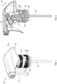
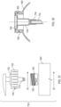
Fig. 1 illustrates a two-part dispensing closure system in accordance with an exemplary embodiment of the invention; -
Fig. 2 is a cross-sectional view thereof taken along line 2-2 ofFig. 1 ; -
Fig. 3 is an exploded perspective view thereof; -
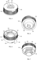
Figs. 4-5 are perspective views of the upper closure portion; -
Figs. 6-7 are perspective views of the lower closure portion; -
Fig. 8 is an enlarged perspective view of the closure assembly with the peel-away spacer intact; -
Fig. 9 is a cross-sectional view thereof taken along line 9-9 ofFig. 8 ; -
Fig. 10 is an enlarged perspective view of the closure assembly with the peel-away spacer removed; -
Fig. 11 is a cross-sectional view thereof taken along line 11-11 ofFig. 10 ; -
Fig. 12 is a perspective view of another exemplary embodiment including an alternative spray dispensing head; -
Fig. 13 is a cross-sectional view thereof taken along line 13-13 ofFig. 12 ; -
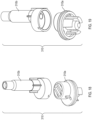
Figs. 14-15 are exploded perspective views of the two-piece piercing probe thereof; -
Fig. 16 is a perspective view of yet another exemplary embodiment including another alternative spray dispensing head; -
Fig. 17 is a cross-sectional view thereof taken along line 17-17 ofFig. 16 ; -
Figs. 18-19 are exploded perspective views of the two-piece piercing probe thereof; -
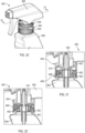
Fig. 20 is a perspective view of another exemplary embodiment including a narrower peel away spacing strip; -
Fig. 21 is a cross-sectional view thereof taken along line 21-21 ofFig. 20 ; -
Fig. 22 is another cross-sectional view thereof with the spacing strip removed and the upper closure portion tightened down onto the lower closure portion; -
Fig. 23 is a perspective view of still another exemplary embodiment including a peel away strip and in internal bottle neck adapter; -
Fig. 24 is a cross-sectional view thereof taken along line 24-24 ofFig. 23 ; -
Fig. 25 is another cross-sectional view thereof with the spacing strip removed and the upper closure portion tightened down onto the bottle neck; -
Fig. 26 is an exploded view of the adapter, closure and seal thereof; -
Fig. 27 is a perspective view of a further exemplary embodiment including an internal adapter cup and a reversible piercing probe; -
Fig. 28 is an exploded view thereof; -
Fig. 29 is a cross-sectional view thereof taken along line 29-29 ofFig. 2 7 ; -
Fig. 30 is another cross-sectional view illustrating the piercing probe in the use position; -
Fig. 31 illustrates a further exemplary embodiment including temporary physical stops on the closure portions; and -
Fig. 31 is a cross-sectional view thereof taken along line 32-32 ofFig. 31 . - Certain exemplary embodiments will now be described to provide an overall understanding of the principles of the structure, function, manufacture, and use of the device and methods disclosed herein. One or more examples of these embodiments are illustrated in the accompanying drawings. Those skilled in the art will understand that the devices and methods specifically described herein and illustrated in the accompanying drawings are non-limiting exemplary embodiments and that the scope of the present invention is defined solely by the claims. The features illustrated or described in connection with one exemplary embodiment may be combined with the features of other embodiments. Such modifications and variations are intended to be included within the scope of the present disclosure. Further, in the present disclosure, like-numbered components of the embodiments generally have similar features, and thus within a particular embodiment each feature of each like-numbered component is not necessarily fully elaborated upon. Additionally, to the extent that linear or circular dimensions are used in the description of the disclosed systems, devices, and methods, such dimensions are not intended to limit the types of shapes that can be used in conjunction with such systems, devices, and methods. Further, to the extent that directional terms like top, bottom, up, or down are used, they are not intended to limit the systems, devices, and methods disclosed herein. A person skilled in the art will recognize that these terms are merely relative to the system and device being discussed and are not universal.
- According to certain exemplary embodiments of the invention as described herein, the present disclosure generally provides a two-part dispensing closure system including features for preventing leaks during the shipment and handling of individual e-commerce sales.
- Referring to
Figs. 1-11 , and according to some embodiments of the invention, adispensing closure system 100 comprises a dispensinghead 102, anupper closure portion 104, alower closure portion 106, aninternal seal 108 to prevent leaks during e-commerce shipment of individual units and a piercingprobe 110. Theclosure system 100 is mounted on theneck 902 of acontainer 900 which contains a liquid product for dispensing. - The
exemplary dispensing head 102 is illustrated as a spray-type trigger dispenser head with a dependingthroat portion 112 that is snap received with theupper closure portion 104. Thethroat portion 112 has an axially centeredflow path 114 to thetrigger piston chamber 116. Referring toFig. 2 , the lower edge of the throat portion includes an outwardly turnedflange 118 which is snap received beneath correspondingridges 120 projecting inwardly from anouter skirt 122 of theupper closure portion 104. This mounting arrangement allows the dispensinghead 102 to rotate relative to theupper closure portion 104 for filling line handling and torqueing of theclosure 100 onto thebottle 900 while maintaining dispensing head orientation relative to the bottle orcontainer 900. - The
lower closure portion 106 has anouter skirt 124 which is threadedly received with theneck 902 of thecontainer 900 and it further includes anaxial flow conduit 126 and avent conduit 128 adjacent to theflow conduit 126. Agasket 130 may be received between thelower closure portion 106 and theneck 902 of thecontainer 900 to form a better seal with thecontainer 900. Adip tube 132 extends from adip tube port 134 on the bottom of theflow conduit 126. Anannular neck 136 extending from theupper closure portion 104 is threadedly mated with a correspondingannular recess 138 in thelower closure portion 106 and is axially movable relative to lowerclosure portion 106 upon rotation thereof. In this regard, theupper closure portion 104 is movable between an extended shipping position (SeeFigs. 8 and 9 ) and a contracted dispensing position (SeeFigs. 10 and 11 ) which will be described further herein. - As best seen in
Figs. 3 and9 , to create a seal during shipping, theseal 108 is disposed on an upper surface of thelower closure portion 106 over both theflow conduit 126 and thevent conduit 128. Theseal 108 may be a foil seal or other suitable type seal which is capable of being pierced and thereafter not obstructing the flow path once pierced. Thevent conduit 128 is preferably located within a concentricannular recess 140 immediately adjacent to theaxial flow conduit 126 and theseal 108 extends over both thecentral flow conduit 126 and theannular recess 140. - Referring to
Figs. 8-11 , to prevent movement of the upper closure relative to the lower closure during shipment and handling, aperipheral spacing strip 142 is removably secured to a lower lip of theouter skirt 122 on theupper closure portion 104. Theremovable spacing strip 142 is attached by a weakenedtear line 144 and includes apull tab 146 for grasping and pulling or tearing thestrip 142 for removal. In the described embodiment, thespacing strip 142 engages the top deck of the lower closure 106 (SeeFig. 9 ) and prevents relative downward movement thereof. - The
tubular piercing probe 110 has anupper portion 148 received in theflow path 114 of the dispensinghead 102 and alower portion 150 extending axially through theupper closure portion 104. Thelower portion 150 includes piercingelements 152 in alignment with theflow conduit 126 and thevent conduit 128 for piercing thereof. - Still referring to
Figs. 8-11 , in use, the piercingelements 152 are spaced from theseal 108 when theupper closure portion 104 is in the inactive extended shipping position (Figs. 8-9 ). However, when thespacing strip 142 is removed and theupper closure portion 104 is rotated relative to thelower closure portion 106 and axially moved from the inactive shipping position to the active dispensing position (Figs. 10-11 ) the piercingelements 152 move downwardly and pierce thefoil seal 108 to open theflow conduit 126 and thevent conduit 128 and allow liquid from thecontainer 900 to travel through the piercingprobe 110 into the dispensing head 102 (See arrow inFig. 11 ). - In some embodiments, the
skirt 124 of thelower closure portion 106 may be secured to thecontainer neck 902 by a bayonet connection. - In some embodiments, the spray dispensing head may have an offset flow conduit. Referring to
Figs. 12-15 , another exemplary embodiment is generally indicated at 200 and includes a dispensinghead 202, anupper closure portion 204, alower closure portion 206, aninternal seal 208 and a piercingprobe 210. - The dispensing
head 202 includes an offsetflow conduit 214. It is a feature of the present embodiments that the piercing probe is located coaxial to the flow conduit in the lower dispensing closure so that upon rotation, the piercing elements are axially moved to pierce the seal in the required locations. In order to allow rotation of dispensinghead 202 with an offsetflow conduit 214 relative to theupper closure portion 204 and rotation of theupper closure portion 204 relative to thelower closure portion 206, the piercingprobe 210 is separated into two discrete components 210A,210B (SeeFigs. 14 and 15 ). The lower piercing component 210A provides the axially oriented piercingelements 252 while theupper component 210 provides the offsetstem portion 248 extending upwardly for receipt into theflow conduit 214. Otherwise, the upper and lower closure portions 204,206 are the same as described hereinabove. - Similarly, illustrated in
Figs. 16-19 is another exemplary embodiment generally indicated at 300 and including a dispensinghead 302, anupper closure portion 304, alower closure portion 306, aninternal seal 308 and a piercingprobe 310. - This embodiment has a slightly different
spray head configuration 302, but also including an offsetflow path 314 through the throat. The upper and lower piercing components 310A,310B are similar to those previously described (210A,201B). - Referring now to
Figs. 20-22 , another exemplary embodiment is illustrated and generally indicated at 400. Thisembodiment 400 also includes a dispensinghead 402,upper closure portion 404,lower closure portion 406,seal 408 and piercingprobe 410 as previously described. Thecurrent embodiment 400 however, has a lower height profile and takes advantage of anarrower spacing strip 442 between theupper closure portion 404 and thelower closure portion 406. The lower profile also requires slightly shorter piercingelements 452 on the piercingprobe 410, but it otherwise structurally and functionally the same asembodiment 100 described hereinabove. - In some embodiments not according to the claims, the lower closure portion is seated within the
neck 902 of thecontainer 900 and the outer skirt of the upper closure portion is threaded for mounting directly onto the container neck. Referring toFigs. 23-26 , an embodiment in this configuration is generally indicated at 500. The dispensingclosure system 500 includes a dispensinghead 502, alower closure portion 506 received and seated within theneck 902 of thecontainer 900, anupper closure portion 504 having anouter skirt 522 that is somewhat elongated or extended, aseal 508 and acoaxial piercing probe 510. In contrast with the previous embodiments, the tear awayspacing strip 542 on the bottom of theskirt 522 engages ashoulder portion 904 of thecontainer 900, rather than the lower closure portion, to prevent rotation and movement of theupper closure portion 504 as previously described. - As best seen in
Fig. 26 , thelower closure portion 504 has anaxial flow conduit 526 as well asvent conduits 528 which are located within correspondingrecesses 540 concentrically surrounding theflow conduit 526. Theseal 508 is disposed over the entire upper surface of thelower closure portion 504 to seal both theflow conduit 526 and the ventingconduits 528. The piercingprobe 510 has a central axial piercing element 552A for theflow conduit 526 and aligned concentric elements 552B for the recesses 540 (better seen inFigs. 24-25 ). - In use, the piercing elements 552A,552B are spaced from the
seal 508 when theupper closure portion 504 is in the inactive extended shipping position (Fig. 24 ). However, when thespacing strip 542 is removed and theupper closure portion 504 is rotated (on the container neck 902) and axially moved from the inactive shipping position to the active dispensing position (Fig. 25 ) the piercing elements 552A,552B move downwardly and pierce thefoil seal 508 to open theflow conduit 526 and thevent conduits 528 and allow liquid from thecontainer 900 to travel through the piercingprobe 510 into the dispensing head 502 (See arrow inFig. 25 ). - In another exemplary embodiment, not according to the claims, indicated at 600 and illustrated in
Figs. 27-30 , aclosure system 600 comprises aspray dispensing head 602, aclosure ring 604 receiving the dispensinghead 602, a cup-shapedbottle adapter 604 having anaxial flow conduit 608 and avent conduit 610 adjacent to theflow conduit 608, a reversibletubular flow adapter 612, and a user-removable seal 614. - The
bottle adapter 606 is received and supported within theneck 902 of thecontainer 900 and adip tube 616 extends from adip tube port 618 on the bottom wall of theadapter 606. Thevent conduit 610 may be in the bottom wall as well, adjacent to theflow conduit 608. - The reversible
tubular flow adapter 612 has astem portion 620 at a first end and an annularconcentric seat portion 622 at a second end. Theflow adapter 612 provides two different functions depending on its deployed configuration. - In a shipping configuration (
Fig. 29 ), thestem portion 620 is received into theaxial flow conduit 608 of thebottle adapter 606 with theseat portion 622 sitting within the of thebottle adapter 606. Theremovable seal 614 is adhered around the peripheral upper lip 624 of thebottle adapter 606 to create a seal and prevent leaks through either theflow conduit 608 or thevent conduit 610. Theseal 614 may include a transversely oriented pull tab to facilitate removal by the consumer. Theclosure ring 604 captures thebottle adapter 604 within the container neck 905 until it reaches the end consumer. Once received, the user removes (unscrews) theclosure ring 604, removes (peels away) theseal 614, removes theflow adapter 612 and reverses the flow adapter configuration to mount theseat portion end 622 onto the flow conduit 608 (SeeFig. 30 ). Theclosure ring 604 anddispenser head 602 are reattached with thestem portion 620 of theflow adapter 608 now extending up into theflow conduit 626 of thedispenser head 602 for normal use. Agasket ring 628 may be received between theclosure ring 604 and thebottle adapter 606. Thegasket ring 628 includes acentral opening 630 through which theflow adapter 612 extends and operates to stabilize the axial orientation of theflow adapter 612 and flowconduit 626 in the deployed dispensing configuration. - In some embodiments, the thread paths in the upper and lower closures may include molded stops to provide temporary physical stops during initial capping. Referring to
Figs. 31 - 32 , an embodiment, not according to the claims, in this configuration is generally indicated at 700. The dispensingclosure system 700 includes a pump-style dispensing head 702, alower closure portion 706 received on theneck 902 of thecontainer 900, and anupper closure portion 704 having anouter skirt 722. - The skirt of the
lower closure 706 is inwardly threaded to engage with thecontainer neck 902 and also outwardly threaded to receive theouter skirt 722 of theupper closure 704. Thelower closure 706 includes anaxial flow conduit 726 with adip tube port 734 anddip tube 732. Aseal 708 is received over theaxial flow conduit 726. - The
upper closure 704 includes acoaxial piercing probe 710 which is configured to mate with and be received within theaxial flow conduit 726 when fully deployed. - In contrast with the previous embodiments, the thread paths of the upper and
lower closures nubs 760 which provide temporary physical stops for rotation of theupper closure 704 relative to thelower closure 706 during initial capping (stops 760 only shown on lower closure 706). - When initially capped, stops 760 engage and position the piercing
probe 710 spaced above theseal 708. However, when the consumer receives the product, the consumer can force further rotation of the upper closure portion 704 (and dispensing head 702), beyond thestops 760, from the inactive shipping position to an active dispensing position. The piercingprobe 710 moves downwardly into theflow conduit 726 and pierces thefoil seal 708 to open theflow conduit 726 and allow product from thecontainer 900 to travel through the piercingprobe 710 into the dispensing head 702. Thelower closure 706 may also include a venting passage. - The exemplary embodiments as illustrated depict both a spray-type dispensing head for liquids as well as a pump-style dispensing head. It should be understood that some embodiments of the invention may include other pump dispensers, pump engines and/or other dispenser heads for dispensing shampoos, soaps, lotions, gels and other viscous and non-viscous flowable products. Any container holding a liquid or flowable product would benefit from the present technology.
- It should be noted each of the components of the exemplary embodiments may be molded from polymers, plastics, urethanes or otherwise formed from suitable materials as desired and may formed by any suitable manufacturing techniques available in the industry.
- It can therefore be seen that the present disclosure provides for a novel dispensing closure system for liquid products which reduces leaks during shipment and handling of individual container units in e-commerce distribution systems. The internal shipping seal and closure locking systems provide two separate protections for preventing leaks from occurring during such e-commerce shipments.
- Having thus described certain particular embodiments of the invention, it is understood that the invention defined by the appended claims is not to be limited by particular details set forth in the above description, as many apparent variations thereof are contemplated. Rather, the invention is limited only by the appended claims.
Claims (10)
- A lower closure portion (106) for use in a dispensing closure system comprising a container; a dispensing head; and an upper closure portion receiving the dispensing head;
the lower closure portion (106) including:an outer skirt (124) comprising an inwardly threaded interior portion for threadedly engaging a neck of a container;an inwardly threaded portion on an annular recess (138) for threadedly mating with an annular neck (136) extending from an upper closure portion (104) such that the lower closure portion (106) is axially movable relative to the upper closure portion (104) when assembled therewith and upon rotation thereof;the lower closure portion (106) further comprising an axial flow conduit (126);a vent conduit (128) adjacent to the flow conduit (126); anda seal disposed on an upper surface of said lower closure portion over the flow conduit (126) and the vent conduit (128) for obstructing the axial flow conduit (126) and for creating a seal for use during shipping of a dispenser comprising the lower closure portion (106). - A dispensing closure system (100) comprising the lower closure portion (106) according to claim 1; a dispensing head (102); an upper closure portion (104) receiving the dispensing head; and a container (900) having a neck (902) to which the outer skirt (124) of the lower closure portion (106) is threadedly engaged.
- A dispensing closure system (100) according to claim 2 further comprisinga peripheral spacing strip (142) removably secured to said upper closure portion (104); anda tubular piercing probe (110) having an upper portion (148) received in the dispensing head (102) and a lower portion (150) extending through the upper closure portion (104), said lower portion (150) including piercing elements (152) disposed in alignment with the flow conduit (126) and the vent conduit (128),said piercing elements being spaced from the seal when the upper closure portion is in an inactive shipping position and piercing said seal to open said flow conduit and said vent conduit when said spacing strip (142) is removed and said upper closure portion is axially moved from said inactive shipping position to an active dispensing position.
- The dispensing closure system of claim 3 wherein said dispensing head is rotatably received with said upper closure portion.
- The dispensing closure system of claim 3 wherein the peripheral spacing strip engages said lower closure portion.
- A dispensing closure system comprising:a dispensing head having a throat portion;an upper closure portion receiving the throat portion of the dispensing head;a lower closure portion according to claim 1;said upper closure portion being received with said lower closure portion and being axially movable relative to said lower closure portion between an inactive shipping position and an active dispensing position;a peripheral spacing strip removably secured to an outer skirt of said upper closure portion, said spacing strip normally maintaining said upper closure portion in said inactive shipping position; anda tubular piercing probe (114) having an upper portion received in the throat portion of the dispensing head and a lower portion extending through the upper closure portion, said lower portion including piercing elements disposed in alignment with the flow conduit and the vent conduit,said piercing elements being spaced from the seal when the upper closure portion is in the inactive shipping position and piercing said seal to open said flow conduit and said vent conduit when said spacing strip is removed and said upper closure portion is axially moved from said inactive shipping position to said active dispensing position.
- The dispensing closure system of claim 6 wherein said upper closure portion includes an outwardly threaded neck.
- The dispensing closure system of claim 6 wherein said throat of said dispensing head is rotatably received with said upper closure portion.
- The dispensing closure system of claim 6 wherein the peripheral spacing strip engages said lower closure portion.
- The dispensing closure system of claim 6 wherein the lower closure portion is seated within the container neck, the outer skirt of the lower closure portion engages with the neck of the container and said spacing strip engages a top deck of the lower closure portion.
Priority Applications (1)
| Application Number | Priority Date | Filing Date | Title |
|---|---|---|---|
| EP24223003.5A EP4509424A3 (en) | 2018-11-15 | 2019-10-28 | Two-part dispensing closure system with internal shipping seal and methods of using the same |
Applications Claiming Priority (2)
| Application Number | Priority Date | Filing Date | Title |
|---|---|---|---|
| US16/191,736 US10676259B1 (en) | 2018-11-15 | 2018-11-15 | Two-part dispensing closure system with internal seal and methods of using the same |
| PCT/US2019/058301 WO2020101873A1 (en) | 2018-11-15 | 2019-10-28 | Two-part dispensing closure system with internal shipping seal and methods of using the same |
Related Child Applications (1)
| Application Number | Title | Priority Date | Filing Date |
|---|---|---|---|
| EP24223003.5A Division EP4509424A3 (en) | 2018-11-15 | 2019-10-28 | Two-part dispensing closure system with internal shipping seal and methods of using the same |
Publications (3)
| Publication Number | Publication Date |
|---|---|
| EP3880576A1 EP3880576A1 (en) | 2021-09-22 |
| EP3880576A4 EP3880576A4 (en) | 2022-10-19 |
| EP3880576B1 true EP3880576B1 (en) | 2024-12-25 |
Family
ID=70728631
Family Applications (2)
| Application Number | Title | Priority Date | Filing Date |
|---|---|---|---|
| EP19884300.5A Active EP3880576B1 (en) | 2018-11-15 | 2019-10-28 | Two-part dispensing closure system with internal shipping seal and methods of using the same |
| EP24223003.5A Pending EP4509424A3 (en) | 2018-11-15 | 2019-10-28 | Two-part dispensing closure system with internal shipping seal and methods of using the same |
Family Applications After (1)
| Application Number | Title | Priority Date | Filing Date |
|---|---|---|---|
| EP24223003.5A Pending EP4509424A3 (en) | 2018-11-15 | 2019-10-28 | Two-part dispensing closure system with internal shipping seal and methods of using the same |
Country Status (4)
| Country | Link |
|---|---|
| US (4) | US10676259B1 (en) |
| EP (2) | EP3880576B1 (en) |
| CN (1) | CN113302136B (en) |
| WO (1) | WO2020101873A1 (en) |
Families Citing this family (5)
| Publication number | Priority date | Publication date | Assignee | Title |
|---|---|---|---|---|
| CL2021000082S1 (en) * | 2020-07-30 | 2021-05-24 | Kh Lloreda S A | Spray gun head. |
| US20240025603A1 (en) * | 2020-10-30 | 2024-01-25 | C-Loop Packaging Sweden Ab | Patterned can end modular dispensing systems with enhanced recyclability |
| FR3120056B1 (en) * | 2021-02-23 | 2024-05-17 | Aptar France Sas | Fluid product reservoir and dispenser |
| CN113879692B (en) * | 2021-10-16 | 2024-10-18 | 上海洁诺德塑胶制品有限公司 | Pump cover and container having the pump cover |
| CN115957903A (en) * | 2023-02-21 | 2023-04-14 | 宁波金雨科技实业有限公司 | Spray gun head and sprayer applying same |
Family Cites Families (38)
| Publication number | Priority date | Publication date | Assignee | Title |
|---|---|---|---|---|
| US2771218A (en) * | 1954-05-19 | 1956-11-20 | Henderson Edward | Closure assembly |
| US3208639A (en) * | 1964-05-06 | 1965-09-28 | Finesse Products Inc | Sealed fluid dispensing system for oxidizable fluids |
| US3780951A (en) * | 1973-01-30 | 1973-12-25 | Afa Corp | Leakproof head for hand sprayer |
| US4011288A (en) * | 1975-03-14 | 1977-03-08 | Baxter Travenol Laboratories, Inc. | Disposable humidifier assembly |
| JPS5927389A (en) * | 1982-08-02 | 1984-02-13 | ザ・コカ−コ−ラ・カンパニ− | Method of conveying and cooking condensed syrup and mount used therefor |
| US5400923A (en) * | 1988-06-20 | 1995-03-28 | Helena Laboratories Corporation | Apparatus for discharging contents of a sealed container |
| KR0151549B1 (en) * | 1989-12-28 | 1999-05-15 | 요시노 야따로오 | Ejector |
| BR9206260A (en) * | 1991-07-10 | 1995-10-10 | Beeson & Sons Ltd | Lid and container set Sealing set for the neck of a container Lid suitable for fitting to the neck of a container Lid resistant to the action of children Container and lid neck for the same lid fitted with a tamper evident ring and process and apparatus for form a container |
| DE69311769T2 (en) * | 1992-01-31 | 1998-01-29 | Contico International, Inc., St. Louis, Mo. | LIQUID DISPENSER DEVICE WITH ADAPTER |
| US5318206A (en) * | 1992-02-24 | 1994-06-07 | Afa Products, Inc. | Trigger-piston connection |
| US5335821A (en) * | 1992-09-11 | 1994-08-09 | Now Technologies, Inc. | Liquid chemical container and dispensing system |
| US5875936A (en) * | 1996-01-22 | 1999-03-02 | Chesebrough-Pond's Usa Co., Division Of Conopco, Inc. | Refillable pump dispenser and refill cartridge |
| US6142345A (en) * | 1998-01-16 | 2000-11-07 | Laible; Rodney | Closed loop dispensing system |
| US6708852B2 (en) * | 2001-08-20 | 2004-03-23 | Alternative Packaging Solutions, L.P. | Non-chemical aerosol dispenser |
| US7427005B1 (en) * | 2002-11-27 | 2008-09-23 | Owens-Illinois Closure Inc. | Dispensing closure, package and method of assembly with film seal piercing |
| US7686194B2 (en) * | 2003-09-03 | 2010-03-30 | Rieke Corporation | Closed loop fluid dispensing system |
| US8714808B2 (en) * | 2004-09-29 | 2014-05-06 | Yoshino Kogyosho Co., Ltd. | Container for mixing two fluids |
| CN1308188C (en) * | 2004-10-08 | 2007-04-04 | 蒋一新 | Liquid packaging bottle twist cap |
| DE102005024439A1 (en) * | 2005-05-24 | 2006-12-07 | Boehringer Ingelheim International Gmbh | atomizer |
| FR2927888B1 (en) * | 2008-02-25 | 2013-03-22 | Seriplast | > |
| WO2010029585A1 (en) * | 2008-09-10 | 2010-03-18 | Bormioli Rocco & Figlio S.P.A. | Security capsule with breakable reservoir and cutter |
| US8083107B2 (en) * | 2009-04-09 | 2011-12-27 | Rodney Laible | Closed loop dispensing system with mechanical venting means |
| WO2011019217A2 (en) * | 2009-08-12 | 2011-02-17 | (주)연우 | Cosmetic container capable of mixed use of different kinds of contents |
| PE20130037A1 (en) * | 2009-11-25 | 2013-02-03 | Boehringer Ingelheim Int | Nebulizer |
| IT1399758B1 (en) * | 2010-04-30 | 2013-05-03 | Capsol S P A | "REFINED TANK CAP" |
| US20120104048A1 (en) * | 2010-10-27 | 2012-05-03 | Hsih Tung Tooling Co.,Ltd. | Foam dispensing device |
| CN103391887A (en) * | 2011-03-08 | 2013-11-13 | Csp技术公司 | Cap and container assembly for a dosage product |
| EP2700588B1 (en) * | 2012-08-21 | 2015-04-01 | Aptar France SAS | Dispensing closure having a vent valve |
| WO2014151208A2 (en) * | 2013-03-15 | 2014-09-25 | Mwv Slatersville, Llc | Vented closure assembly for a spray container |
| EP3033279B1 (en) * | 2013-08-16 | 2019-03-13 | Silgan Dispensing Systems Slatersville LLC | Dispensing closure |
| DE102014113391A1 (en) * | 2014-05-07 | 2015-11-12 | Gizmo Packaging Limited | Closure device for a container |
| GB201415869D0 (en) * | 2014-09-08 | 2014-10-22 | Eulysis Uk Ltd | Container And Closure |
| US20170355496A1 (en) * | 2014-12-15 | 2017-12-14 | Bevaswiss Ag | Fillable closure device with push-button for releasing |
| ITUB20159655A1 (en) * | 2015-12-23 | 2017-06-23 | Bormioli Rocco Spa | Safety capsule of a container. |
| FR3050183B1 (en) * | 2016-04-19 | 2018-10-12 | Albea Services | PERFORATOR CAP IN PARTICULAR FOR A FLEXIBLE TUBE |
| DE102017126965A1 (en) * | 2017-11-16 | 2019-05-16 | Bericap Holding Gmbh | Plastic closure with detachable membrane |
| IT201800002518A1 (en) * | 2018-02-08 | 2019-08-08 | Bormioli Pharma Spa | CAPSULE FOR CLOSING A CONTAINER |
| DE102018002101B4 (en) * | 2018-03-15 | 2026-04-30 | Aptar Dortmund Gmbh | Dispensing storage and dispenser |
-
2018
- 2018-11-15 US US16/191,736 patent/US10676259B1/en active Active
-
2019
- 2019-10-28 EP EP19884300.5A patent/EP3880576B1/en active Active
- 2019-10-28 WO PCT/US2019/058301 patent/WO2020101873A1/en not_active Ceased
- 2019-10-28 CN CN201980089011.2A patent/CN113302136B/en active Active
- 2019-10-28 EP EP24223003.5A patent/EP4509424A3/en active Pending
-
2020
- 2020-06-08 US US16/895,193 patent/US11027898B2/en active Active
-
2021
- 2021-05-27 US US17/332,282 patent/US11377273B2/en active Active
-
2022
- 2022-06-14 US US17/840,273 patent/US11679916B2/en active Active
Also Published As
| Publication number | Publication date |
|---|---|
| EP3880576A4 (en) | 2022-10-19 |
| EP3880576A1 (en) | 2021-09-22 |
| US11679916B2 (en) | 2023-06-20 |
| EP4509424A3 (en) | 2025-05-07 |
| US20200354121A1 (en) | 2020-11-12 |
| US10676259B1 (en) | 2020-06-09 |
| CN113302136B (en) | 2023-04-04 |
| US11027898B2 (en) | 2021-06-08 |
| EP4509424A2 (en) | 2025-02-19 |
| CN113302136A (en) | 2021-08-24 |
| US20200156833A1 (en) | 2020-05-21 |
| US20210284403A1 (en) | 2021-09-16 |
| US11377273B2 (en) | 2022-07-05 |
| US20220306359A1 (en) | 2022-09-29 |
| WO2020101873A1 (en) | 2020-05-22 |
Similar Documents
| Publication | Publication Date | Title |
|---|---|---|
| US11679916B2 (en) | Two-part dispensing closure system with internal seal and methods of using the same | |
| US5934514A (en) | Dispensing valve closure with inner seal | |
| US8807340B2 (en) | Beverage glass and beverage glass assembly | |
| US8887905B2 (en) | Plastic closure having a capsule for dispensing active ingredients | |
| US10442585B2 (en) | Closure for a container | |
| JP2005511440A (en) | Closure with internal flow control device for pressure on / off valve in telescopic nozzle | |
| US12454395B2 (en) | Dispensing closure | |
| EP3870517B1 (en) | Dispensing closure for a container | |
| CN105916778B (en) | Distribution capping and the container covered with such distribution | |
| US11858684B2 (en) | Dispensing system | |
| US20130068799A1 (en) | Retractable spout assemblies for containers, and containers having such assemblies mounted therein | |
| US20120055945A1 (en) | Closure-sealing system for rotational opening | |
| RU2459750C2 (en) | Container for beverages | |
| WO2008042737A2 (en) | Dispensing closure for wet aseptic and low pressure applications | |
| GB2599754A (en) | A transit sealing plug | |
| JP3211486U (en) | Improvements in or on push-pull closures | |
| NZ213942A (en) | Two-piece, adjustable orifice dispensing closure | |
| BR102016005783B1 (en) | Aerosol valve and container assembly; and; gasification method of valve assembly and aerosol container |
Legal Events
| Date | Code | Title | Description |
|---|---|---|---|
| STAA | Information on the status of an ep patent application or granted ep patent |
Free format text: STATUS: THE INTERNATIONAL PUBLICATION HAS BEEN MADE |
|
| PUAI | Public reference made under article 153(3) epc to a published international application that has entered the european phase |
Free format text: ORIGINAL CODE: 0009012 |
|
| STAA | Information on the status of an ep patent application or granted ep patent |
Free format text: STATUS: REQUEST FOR EXAMINATION WAS MADE |
|
| 17P | Request for examination filed |
Effective date: 20210615 |
|
| AK | Designated contracting states |
Kind code of ref document: A1 Designated state(s): AL AT BE BG CH CY CZ DE DK EE ES FI FR GB GR HR HU IE IS IT LI LT LU LV MC MK MT NL NO PL PT RO RS SE SI SK SM TR |
|
| DAV | Request for validation of the european patent (deleted) | ||
| DAX | Request for extension of the european patent (deleted) | ||
| A4 | Supplementary search report drawn up and despatched |
Effective date: 20220920 |
|
| RIC1 | Information provided on ipc code assigned before grant |
Ipc: B65D 51/22 20060101ALI20220914BHEP Ipc: B05B 11/00 20060101ALI20220914BHEP Ipc: B65D 47/20 20060101ALI20220914BHEP Ipc: B65D 51/28 20060101ALI20220914BHEP Ipc: B65D 51/16 20060101ALI20220914BHEP Ipc: B65D 51/00 20060101AFI20220914BHEP |
|
| GRAP | Despatch of communication of intention to grant a patent |
Free format text: ORIGINAL CODE: EPIDOSNIGR1 |
|
| STAA | Information on the status of an ep patent application or granted ep patent |
Free format text: STATUS: GRANT OF PATENT IS INTENDED |
|
| INTG | Intention to grant announced |
Effective date: 20240715 |
|
| GRAS | Grant fee paid |
Free format text: ORIGINAL CODE: EPIDOSNIGR3 |
|
| GRAA | (expected) grant |
Free format text: ORIGINAL CODE: 0009210 |
|
| STAA | Information on the status of an ep patent application or granted ep patent |
Free format text: STATUS: THE PATENT HAS BEEN GRANTED |
|
| AK | Designated contracting states |
Kind code of ref document: B1 Designated state(s): AL AT BE BG CH CY CZ DE DK EE ES FI FR GB GR HR HU IE IS IT LI LT LU LV MC MK MT NL NO PL PT RO RS SE SI SK SM TR |
|
| REG | Reference to a national code |
Ref country code: GB Ref legal event code: FG4D |
|
| REG | Reference to a national code |
Ref country code: CH Ref legal event code: EP |
|
| REG | Reference to a national code |
Ref country code: DE Ref legal event code: R096 Ref document number: 602019064083 Country of ref document: DE |
|
| REG | Reference to a national code |
Ref country code: IE Ref legal event code: FG4D |
|
| P01 | Opt-out of the competence of the unified patent court (upc) registered |
Free format text: CASE NUMBER: APP_67852/2024 Effective date: 20241223 |
|
| REG | Reference to a national code |
Ref country code: LT Ref legal event code: MG9D |
|
| PG25 | Lapsed in a contracting state [announced via postgrant information from national office to epo] |
Ref country code: HR Free format text: LAPSE BECAUSE OF FAILURE TO SUBMIT A TRANSLATION OF THE DESCRIPTION OR TO PAY THE FEE WITHIN THE PRESCRIBED TIME-LIMIT Effective date: 20241225 |
|
| PG25 | Lapsed in a contracting state [announced via postgrant information from national office to epo] |
Ref country code: FI Free format text: LAPSE BECAUSE OF FAILURE TO SUBMIT A TRANSLATION OF THE DESCRIPTION OR TO PAY THE FEE WITHIN THE PRESCRIBED TIME-LIMIT Effective date: 20241225 |
|
| PG25 | Lapsed in a contracting state [announced via postgrant information from national office to epo] |
Ref country code: BG Free format text: LAPSE BECAUSE OF FAILURE TO SUBMIT A TRANSLATION OF THE DESCRIPTION OR TO PAY THE FEE WITHIN THE PRESCRIBED TIME-LIMIT Effective date: 20241225 |
|
| PG25 | Lapsed in a contracting state [announced via postgrant information from national office to epo] |
Ref country code: NO Free format text: LAPSE BECAUSE OF FAILURE TO SUBMIT A TRANSLATION OF THE DESCRIPTION OR TO PAY THE FEE WITHIN THE PRESCRIBED TIME-LIMIT Effective date: 20250325 |
|
| PG25 | Lapsed in a contracting state [announced via postgrant information from national office to epo] |
Ref country code: LV Free format text: LAPSE BECAUSE OF FAILURE TO SUBMIT A TRANSLATION OF THE DESCRIPTION OR TO PAY THE FEE WITHIN THE PRESCRIBED TIME-LIMIT Effective date: 20241225 Ref country code: GR Free format text: LAPSE BECAUSE OF FAILURE TO SUBMIT A TRANSLATION OF THE DESCRIPTION OR TO PAY THE FEE WITHIN THE PRESCRIBED TIME-LIMIT Effective date: 20250326 |
|
| PG25 | Lapsed in a contracting state [announced via postgrant information from national office to epo] |
Ref country code: RS Free format text: LAPSE BECAUSE OF FAILURE TO SUBMIT A TRANSLATION OF THE DESCRIPTION OR TO PAY THE FEE WITHIN THE PRESCRIBED TIME-LIMIT Effective date: 20250325 |
|
| REG | Reference to a national code |
Ref country code: NL Ref legal event code: MP Effective date: 20241225 |
|
| PG25 | Lapsed in a contracting state [announced via postgrant information from national office to epo] |
Ref country code: NL Free format text: LAPSE BECAUSE OF FAILURE TO SUBMIT A TRANSLATION OF THE DESCRIPTION OR TO PAY THE FEE WITHIN THE PRESCRIBED TIME-LIMIT Effective date: 20241225 |
|
| REG | Reference to a national code |
Ref country code: AT Ref legal event code: MK05 Ref document number: 1754002 Country of ref document: AT Kind code of ref document: T Effective date: 20241225 |
|
| PG25 | Lapsed in a contracting state [announced via postgrant information from national office to epo] |
Ref country code: SM Free format text: LAPSE BECAUSE OF FAILURE TO SUBMIT A TRANSLATION OF THE DESCRIPTION OR TO PAY THE FEE WITHIN THE PRESCRIBED TIME-LIMIT Effective date: 20241225 |
|
| PG25 | Lapsed in a contracting state [announced via postgrant information from national office to epo] |
Ref country code: PL Free format text: LAPSE BECAUSE OF FAILURE TO SUBMIT A TRANSLATION OF THE DESCRIPTION OR TO PAY THE FEE WITHIN THE PRESCRIBED TIME-LIMIT Effective date: 20241225 |
|
| PG25 | Lapsed in a contracting state [announced via postgrant information from national office to epo] |
Ref country code: ES Free format text: LAPSE BECAUSE OF FAILURE TO SUBMIT A TRANSLATION OF THE DESCRIPTION OR TO PAY THE FEE WITHIN THE PRESCRIBED TIME-LIMIT Effective date: 20241225 |
|
| PG25 | Lapsed in a contracting state [announced via postgrant information from national office to epo] |
Ref country code: IS Free format text: LAPSE BECAUSE OF FAILURE TO SUBMIT A TRANSLATION OF THE DESCRIPTION OR TO PAY THE FEE WITHIN THE PRESCRIBED TIME-LIMIT Effective date: 20250425 |
|
| PG25 | Lapsed in a contracting state [announced via postgrant information from national office to epo] |
Ref country code: PT Free format text: LAPSE BECAUSE OF FAILURE TO SUBMIT A TRANSLATION OF THE DESCRIPTION OR TO PAY THE FEE WITHIN THE PRESCRIBED TIME-LIMIT Effective date: 20250428 |
|
| PG25 | Lapsed in a contracting state [announced via postgrant information from national office to epo] |
Ref country code: EE Free format text: LAPSE BECAUSE OF FAILURE TO SUBMIT A TRANSLATION OF THE DESCRIPTION OR TO PAY THE FEE WITHIN THE PRESCRIBED TIME-LIMIT Effective date: 20241225 |
|
| PG25 | Lapsed in a contracting state [announced via postgrant information from national office to epo] |
Ref country code: RO Free format text: LAPSE BECAUSE OF FAILURE TO SUBMIT A TRANSLATION OF THE DESCRIPTION OR TO PAY THE FEE WITHIN THE PRESCRIBED TIME-LIMIT Effective date: 20241225 Ref country code: AT Free format text: LAPSE BECAUSE OF FAILURE TO SUBMIT A TRANSLATION OF THE DESCRIPTION OR TO PAY THE FEE WITHIN THE PRESCRIBED TIME-LIMIT Effective date: 20241225 |
|
| PG25 | Lapsed in a contracting state [announced via postgrant information from national office to epo] |
Ref country code: SK Free format text: LAPSE BECAUSE OF FAILURE TO SUBMIT A TRANSLATION OF THE DESCRIPTION OR TO PAY THE FEE WITHIN THE PRESCRIBED TIME-LIMIT Effective date: 20241225 |
|
| PG25 | Lapsed in a contracting state [announced via postgrant information from national office to epo] |
Ref country code: CZ Free format text: LAPSE BECAUSE OF FAILURE TO SUBMIT A TRANSLATION OF THE DESCRIPTION OR TO PAY THE FEE WITHIN THE PRESCRIBED TIME-LIMIT Effective date: 20241225 |
|
| PG25 | Lapsed in a contracting state [announced via postgrant information from national office to epo] |
Ref country code: IT Free format text: LAPSE BECAUSE OF FAILURE TO SUBMIT A TRANSLATION OF THE DESCRIPTION OR TO PAY THE FEE WITHIN THE PRESCRIBED TIME-LIMIT Effective date: 20241225 |
|
| PG25 | Lapsed in a contracting state [announced via postgrant information from national office to epo] |
Ref country code: SE Free format text: LAPSE BECAUSE OF FAILURE TO SUBMIT A TRANSLATION OF THE DESCRIPTION OR TO PAY THE FEE WITHIN THE PRESCRIBED TIME-LIMIT Effective date: 20241225 |
|
| REG | Reference to a national code |
Ref country code: DE Ref legal event code: R097 Ref document number: 602019064083 Country of ref document: DE |
|
| PG25 | Lapsed in a contracting state [announced via postgrant information from national office to epo] |
Ref country code: DK Free format text: LAPSE BECAUSE OF FAILURE TO SUBMIT A TRANSLATION OF THE DESCRIPTION OR TO PAY THE FEE WITHIN THE PRESCRIBED TIME-LIMIT Effective date: 20241225 |
|
| PLBE | No opposition filed within time limit |
Free format text: ORIGINAL CODE: 0009261 |
|
| STAA | Information on the status of an ep patent application or granted ep patent |
Free format text: STATUS: NO OPPOSITION FILED WITHIN TIME LIMIT |
|
| 26N | No opposition filed |
Effective date: 20250926 |
|
| PGFP | Annual fee paid to national office [announced via postgrant information from national office to epo] |
Ref country code: DE Payment date: 20251029 Year of fee payment: 7 |
|
| PGFP | Annual fee paid to national office [announced via postgrant information from national office to epo] |
Ref country code: GB Payment date: 20251027 Year of fee payment: 7 |
|
| PGFP | Annual fee paid to national office [announced via postgrant information from national office to epo] |
Ref country code: FR Payment date: 20251027 Year of fee payment: 7 |