EP3880550B1 - Anchoring device - Google Patents
Anchoring device Download PDFInfo
- Publication number
- EP3880550B1 EP3880550B1 EP19813653.3A EP19813653A EP3880550B1 EP 3880550 B1 EP3880550 B1 EP 3880550B1 EP 19813653 A EP19813653 A EP 19813653A EP 3880550 B1 EP3880550 B1 EP 3880550B1
- Authority
- EP
- European Patent Office
- Prior art keywords
- piston
- anchoring device
- damper
- sliding
- damping
- Prior art date
- Legal status (The legal status is an assumption and is not a legal conclusion. Google has not performed a legal analysis and makes no representation as to the accuracy of the status listed.)
- Active
Links
Images

Classifications
-
- F—MECHANICAL ENGINEERING; LIGHTING; HEATING; WEAPONS; BLASTING
- F16—ENGINEERING ELEMENTS AND UNITS; GENERAL MEASURES FOR PRODUCING AND MAINTAINING EFFECTIVE FUNCTIONING OF MACHINES OR INSTALLATIONS; THERMAL INSULATION IN GENERAL
- F16F—SPRINGS; SHOCK-ABSORBERS; MEANS FOR DAMPING VIBRATION
- F16F15/00—Suppression of vibrations in systems; Means or arrangements for avoiding or reducing out-of-balance forces, e.g. due to motion
- F16F15/02—Suppression of vibrations of non-rotating, e.g. reciprocating systems; Suppression of vibrations of rotating systems by use of members not moving with the rotating systems
- F16F15/03—Suppression of vibrations of non-rotating, e.g. reciprocating systems; Suppression of vibrations of rotating systems by use of members not moving with the rotating systems using magnetic or electromagnetic means
-
- B—PERFORMING OPERATIONS; TRANSPORTING
- B63—SHIPS OR OTHER WATERBORNE VESSELS; RELATED EQUIPMENT
- B63B—SHIPS OR OTHER WATERBORNE VESSELS; EQUIPMENT FOR SHIPPING
- B63B21/00—Tying-up; Shifting, towing, or pushing equipment; Anchoring
- B63B21/04—Fastening or guiding equipment for chains, ropes, hawsers, or the like
-
- F—MECHANICAL ENGINEERING; LIGHTING; HEATING; WEAPONS; BLASTING
- F16—ENGINEERING ELEMENTS AND UNITS; GENERAL MEASURES FOR PRODUCING AND MAINTAINING EFFECTIVE FUNCTIONING OF MACHINES OR INSTALLATIONS; THERMAL INSULATION IN GENERAL
- F16F—SPRINGS; SHOCK-ABSORBERS; MEANS FOR DAMPING VIBRATION
- F16F15/00—Suppression of vibrations in systems; Means or arrangements for avoiding or reducing out-of-balance forces, e.g. due to motion
- F16F15/02—Suppression of vibrations of non-rotating, e.g. reciprocating systems; Suppression of vibrations of rotating systems by use of members not moving with the rotating systems
- F16F15/023—Suppression of vibrations of non-rotating, e.g. reciprocating systems; Suppression of vibrations of rotating systems by use of members not moving with the rotating systems using fluid means
- F16F15/027—Suppression of vibrations of non-rotating, e.g. reciprocating systems; Suppression of vibrations of rotating systems by use of members not moving with the rotating systems using fluid means comprising control arrangements
-
- F—MECHANICAL ENGINEERING; LIGHTING; HEATING; WEAPONS; BLASTING
- F16—ENGINEERING ELEMENTS AND UNITS; GENERAL MEASURES FOR PRODUCING AND MAINTAINING EFFECTIVE FUNCTIONING OF MACHINES OR INSTALLATIONS; THERMAL INSULATION IN GENERAL
- F16F—SPRINGS; SHOCK-ABSORBERS; MEANS FOR DAMPING VIBRATION
- F16F9/00—Springs, vibration-dampers, shock-absorbers, or similarly-constructed movement-dampers using a fluid or the equivalent as damping medium
- F16F9/10—Springs, vibration-dampers, shock-absorbers, or similarly-constructed movement-dampers using a fluid or the equivalent as damping medium using liquid only; using a fluid of which the nature is immaterial
- F16F9/14—Devices with one or more members, e.g. pistons, vanes, moving to and fro in chambers and using throttling effect
- F16F9/16—Devices with one or more members, e.g. pistons, vanes, moving to and fro in chambers and using throttling effect involving only straight-line movement of the effective parts
- F16F9/18—Devices with one or more members, e.g. pistons, vanes, moving to and fro in chambers and using throttling effect involving only straight-line movement of the effective parts with a closed cylinder and a piston separating two or more working spaces therein
- F16F9/19—Devices with one or more members, e.g. pistons, vanes, moving to and fro in chambers and using throttling effect involving only straight-line movement of the effective parts with a closed cylinder and a piston separating two or more working spaces therein with a single cylinder and of single-tube type
-
- B—PERFORMING OPERATIONS; TRANSPORTING
- B63—SHIPS OR OTHER WATERBORNE VESSELS; RELATED EQUIPMENT
- B63B—SHIPS OR OTHER WATERBORNE VESSELS; EQUIPMENT FOR SHIPPING
- B63B21/00—Tying-up; Shifting, towing, or pushing equipment; Anchoring
- B63B2021/003—Mooring or anchoring equipment, not otherwise provided for
- B63B2021/005—Resilient passive elements to be placed in line with mooring or towing chains, or line connections, e.g. dampers or springs
-
- B—PERFORMING OPERATIONS; TRANSPORTING
- B63—SHIPS OR OTHER WATERBORNE VESSELS; RELATED EQUIPMENT
- B63B—SHIPS OR OTHER WATERBORNE VESSELS; EQUIPMENT FOR SHIPPING
- B63B21/00—Tying-up; Shifting, towing, or pushing equipment; Anchoring
- B63B2021/003—Mooring or anchoring equipment, not otherwise provided for
- B63B2021/008—Load monitors
-
- B—PERFORMING OPERATIONS; TRANSPORTING
- B63—SHIPS OR OTHER WATERBORNE VESSELS; RELATED EQUIPMENT
- B63B—SHIPS OR OTHER WATERBORNE VESSELS; EQUIPMENT FOR SHIPPING
- B63B21/00—Tying-up; Shifting, towing, or pushing equipment; Anchoring
- B63B21/50—Anchoring arrangements or methods for special vessels, e.g. for floating drilling platforms or dredgers
-
- F—MECHANICAL ENGINEERING; LIGHTING; HEATING; WEAPONS; BLASTING
- F16—ENGINEERING ELEMENTS AND UNITS; GENERAL MEASURES FOR PRODUCING AND MAINTAINING EFFECTIVE FUNCTIONING OF MACHINES OR INSTALLATIONS; THERMAL INSULATION IN GENERAL
- F16F—SPRINGS; SHOCK-ABSORBERS; MEANS FOR DAMPING VIBRATION
- F16F2232/00—Nature of movement
- F16F2232/06—Translation-to-rotary conversion
Definitions
- This invention relates to an anchoring device of the type specified in the preamble of the first claim.
- the invention relates to a device suitable for securing a floating object (such as a boat or a buoy) to an anchor structure that can be floating or attached to the ground.
- the anchoring device can thus be used to, for example, secure a boat to a floating or fixed quayside.
- anchoring device also identifies a mooring device.
- a mooring spring also called a spring or compensator
- This consists of an elastic body that is fixed to a boat by means of a rope or chain and it protects the mooring from wave motion, guaranteeing greater comfort on board.
- the mooring spring can be made of various materials, such as steel, rubber, or thermoplastic material.
- the anchoring devices i.e. ropes and mooring springs
- the anchoring devices are difficult to adjust and, therefore, if not well held, they can enable the floating object to move considerably relatively to the anchor structure and may, therefore, cause damage to the floating object and/or the anchor structure.
- the well-known anchoring devices have constant stiffness and damping features that often vary with weather conditions, aging, corrosion, etc.
- the technical task underlying this invention is to devise an anchoring device capable of substantially overcoming at least some of the above-mentioned drawbacks.
- an important purpose of the invention is to obtain an anchoring device that is easy to adjust and that, therefore, enables the accurate anchoring of the floating object to the anchor structure.
- the measures, values, shapes, and geometric references when associated with words like “about” or other similar terms such as “approximately” or “substantially”, are to be understood as except for measurement errors or inaccuracies owing to production and/or manufacturing errors and, above all, except for a slight divergence from the value, measure, shape, or geometric reference with which it is associated.
- these terms if associated with a value, preferably indicate a divergence of not more than 10% of the value.
- the number 1 indicates, as a whole, the anchoring device according to the invention.
- a floating object such as a boat or a buoy
- an anchor structure floating or attached to the ground
- the anchoring device 1 comprises a first attachment 2 suitable for being secured to the floating object; and a second attachment 3 suitable for being secured to the anchor structure.
- the first attachment 2 can be secured to the floating object by means of ropes or other suitable connection means, such as chains, metal cables, rods, or shackles (hereinafter called, collectively, ropes). Alternatively, it can be secured to the floating object.
- the second attachment 3 can be secured to the anchor structure by means of ropes. Alternatively, it can be firmly secured to the anchor structure.
- Said attachments 2 and 3 define fastenings that can be done and undone.
- the anchoring device 1 comprises a damping member 4 for the relative motion between the attachments 2 and 3 and, therefore, between the floating object and the anchor structure.
- the damping member 4 comprises a slide chamber 41 defining a slide axis 4a; a piston 42 suitable for sliding, along said axis 4a, in the slide chamber 41 according to a relative motion between the attachments 2 and 3; and at least one damper 43 suitable for damping the sliding of the piston 42 in the slide chamber 41.
- the piston 42 is attached to one of attachments 2 or 3, in particular, to the first attachment 2.
- the slide chamber 41 is attached to an attachment 2 or 3 that is separate from that of the piston 42, and preferably to the second attachment 3.
- the slide chamber 41 can define a watertight internal volume.
- the piston 41 has its head inside the internal volume and the stem partially protruding from it through a hole equipped with sealing means.
- the sliding of the piston 42 and, therefore, the position of the piston 42 defines a contracted configuration for the damping member 4, wherein the distance between the attachments 2 and 3 is minimum, and an expanded configuration, wherein the distance between the attachments 2 and 3 is maximum.
- the damping member 4 may, conveniently, comprise elastic means 44 suitable for working in opposition to a variation in the distance between the attachments 2 and 3 and, in particular, to a transition from the contracted to the expanded configuration.
- the damping member 4 may comprise at least one kinematic mechanism 45 suitable for kinematically connecting the piston 42 and damper 43.
- the member 4 conveniently comprises a kinematic mechanism for the damper 43.
- the kinematic mechanism 45 is a gearing suitable for transforming the rectilinear motion of the piston 42 into a rotary motion at the damper 43.
- the kinematic mechanism 45 can be conveniently fixed in relation to the transmission.
- It may comprise a rack 45a extending along the slide axis 4a; and a toothed wheel 45b suitable for sliding along the rack 45a.
- the rack 45a can be attached to the piston 42.
- the toothed wheel 45b can be attached to the slide chamber 41 and can be controlled in rotation by the rack 45a.
- the kinematic mechanism 45 can comprise a multiplier 45c suitable for multiplying the rotation speed of the rotor, enabling the transition from low speeds, typical of a wave, to a higher speed motion.
- the damping member 4 preferably comprises at least one electric damper 43.
- Said damper 43 is an electric motor suitable for dissipating energy by opposing a reciprocal rotation between stator and rotor.
- the damper 43 is a brushless electric motor.
- said electric motor i.e. the damper 43
- said electric motor can be used to produce energy by exploiting the sliding of the piston 42.
- the damper 43 is attached to the chamber 41.
- the damping member 4 conveniently comprises several dampers 43 that can be controlled by said at least one toothed wheel 45b. More conveniently, the damping member 4 comprises several dampers 43 each of which can be controlled by a toothed wheel 45b; and, in particular, three dampers 43 and three toothed wheels 45b, each of which actuates a damper 43.
- the anchoring device 1 may comprise at least one electrical energy converter 5.
- the converter 5 is suitable for varying the parameters of the electricity output from the damper 43 allowing the use of an external device and/or the same device 1. At least one converter 5 is located in said internal volume.
- the anchoring device 1 may comprise at least one energy storage battery 6 for the output from the converter 5 and/or the damper 43.
- the battery 6 is located in said internal volume.
- the anchoring device 1 can comprise 7 connectors suitable for allowing the electrical connection of an external unit to the device.
- the connectors are external to the volume and in electrical connection with the battery 6 and/or the converter 5.
- the anchoring device 1 may comprise a control unit 8 for the operation of the same device 1.
- the control unit 8 may comprise at least one measurement sensor 81 for measuring the sliding of the piston 42.
- the at least one measurement sensor 81 is suitable for measuring at least one of the following: speed (in module and, conveniently, towards) and acceleration (in module and, conveniently, towards) of the sliding of the piston 42.
- the senor is suitable for measuring speed and acceleration.
- At least one measurement sensor 81 may be suitable for measuring the sliding of the piston 42 in a direct manner. It can thus carry out a direct measurement of the sliding of the piston 42 by measuring its movement and/or position (e.g. a variation in position) along the slide axis 4a.
- the at least one measurement sensor 81 can measure the rotation of the toothed wheel 45b and/or a variation in distance between the piston head 42 and a base of the slide chamber 41.
- the unit conveniently has a sensor 81 for each toothed wheel 45b.
- the at least one measurement sensor 81 can carry out an indirect measurement of the sliding of the piston 42 by measuring the operating parameters of the damper 43.
- the at least one measurement sensor 81 can measure the rotation speed of the rotor of the damper 43.
- the control unit 8 may comprise a control board 82 of the anchoring device 1.
- the control board 82 is in data connection with the damper 43 and, conveniently, with the converter 5 and/or battery 6 so as to monitor the production and status of the electrical energy.
- the control board 82 is in data connection with the one or more sensors present in the device 1.
- the control board 82 is in data connection with the measurement sensor 81.
- the control board 82 may be suitable for varying the damping of the damper 43 according to the sliding of the piston 42 measured by the measurement sensor 81. More specifically, the board 82 varies the damping of the damper 43 based on the speed and/or acceleration of the piston 42. Even more specifically, the control board 82 varies the damping of the damper 43 in accordance with, preferably proportionally to, the speed and/or acceleration of the piston 42.
- the expression “based on” identifies that a variation and, for example, an increase of a first parameter (in this case, the sliding speed of the piston 42) corresponds to any variation (increase or decrease) of the second parameter (in this case, the damping); the expression “in accordance with” identifies that an increase or decrease of a first parameter corresponds, respectively, to an increase or decrease of the second parameter.
- the control board 82 varies the damping of the damper 43 by changing the magnetic parameters of the poles at the stator and/or rotor so as to vary the opposition to the rotation of the rotor. More specifically, the board controls 82 variations in parameters such as polarity, magnetic intensity, and electrical load circuit mode.
- the control board 82 is suitable for maintaining the sliding speed of the piston 42 between a minimum speed and a maximum speed. Therefore, if, for example, the sliding speed of the piston 42 is greater than the maximum speed, the control board 82 controls an increase in damping and, therefore, the damper 43 more strongly opposes the sliding of the piston 42 which slows down.
- the minimum speed is substantially less than 0.06 m/s and, more specifically, substantially between 0.06 m/s and 0.01 m/s and, preferably, between 0.05 m/s and 0.03 m/s. It is, conveniently, substantially equal to at least 0.04 m/s.
- the maximum speed is substantially greater than 0.04 m/s and, more specifically, substantially between 0.1 m/s and 0.04 m/s and, preferably, between 0.07 m/s and 0.05 m/s. It is, conveniently, substantially equal to at least 0.06 m/s.
- the control unit 8 may comprise at least one first force sensor 83 suitable for measuring the force that the floating object applies to the first attachment 2.
- the control board 82 can, therefore, based on a variation in force at said first sensor 83, measure variations in external load (for example, due to a wave or wind) on the floating object.
- the control unit 8 may comprise at least one second force sensor 84 suitable for measuring the force applied by the anchor structure to the second attachment 3.
- control board 82 can, therefore, based on a variation of force at said second sensor 84, measure variations in the external load on the anchor structure due, for example, to movements of the floating object with respect to the anchor structure.
- the control board 82 can vary the damping of the damper 43 based on and preferably in accordance with, preferably proportionally to, said measurements of the one or more force sensors 83 and 84.
- the control unit 8 may comprise a monitoring system for the damper 43 suitable for measuring the parameters of the damper's operation 43.
- the monitoring system may be suitable for measuring the temperature of the damper 43.
- the monitoring system may be suitable for measuring the electrical current parameters (such as amperage and/or voltage) at the output of the damper 43.
- the control unit 8 may comprise at least one environmental sensor set, in data connection with the control board 82, suitable for measuring environmental parameters external to the anchoring device 1.
- the control unit 8 may comprise a first wave motion characterization sensor set.
- Said first sensor set may comprise one or more first environmental sensors, each of which is suitable for identifying the characteristics of the waves, such as the modulus and direction of the current, the height and frequency of the waves.
- the control board 82 may vary the damping of the damper 43.
- the control board 82 preferably varies the damping of the damper 43 in accordance with, preferably proportionally to, the data collected by the first sensor set.
- the control unit 8 may comprise a second sensor set for characterising the water conditions.
- Said second sensor set may comprise one or more second environmental sensors, each of which is suitable for measuring at least one water parameter that can be chosen from: temperature, clarity, presence of pollutants in the water, salinity, depth, and presence of fish.
- the control unit 8 may comprise a third air characterization sensor set.
- Said third sensor set may comprise one or more third environmental sensors, each of which is suitable for measuring one or more air parameters such as temperature, exposure to light, presence of pollutants in the air, modulus and wind direction.
- control unit 8 may comprise a distance gauge.
- control unit 8 may comprise a first distance gauge for gauging the distance between the anchoring device 1 and the floating object; and a second distance gauge for gauging the distance between the anchoring device 1 and the anchor structure.
- the control unit 8 may comprise a geo-localiser suitable for identifying the position of the anchoring device 1.
- the anchoring device 1 may comprise data connection means suitable for allowing a data exchange, preferably a wireless one (using WI-FI, Bluetooth and LoRa), between the control unit 8 and an external unit suitable for monitoring, thanks to the reception of the parameters collected by the control unit 8, the operation of the device 1.
- a data exchange preferably a wireless one (using WI-FI, Bluetooth and LoRa)
- the anchoring device 1 is secured, through the first attachment 2, to the floating object (e.g. a boat or a vessel) and, through the second attachment 3, to an anchor structure.
- the floating object e.g. a boat or a vessel
- the second attachment 3 to an anchor structure.
- the motion of the piston 42 causes the rack 45a to slide, resulting in a rotation of the toothed wheel 45b that, through a kinematic connection mechanism, activates the damper 43, causing the rotor to rotate.
- This rotation of the rotor due to the poles present on the stator, results in both a slowing down of the sliding of the piston, attenuating the motion between the floating object and the anchor structure, and a production of electrical energy that can be used to operate the device 1 and/or to supply an external device.
- control board 82 thanks to the measurement sensor 81, measures the speed of the piston 42 as higher than the maximum speed or lower than the minimum speed, the same control board 82 controls, respectively, an increase or a decrease of the damping of the damper 43 bringing the speed of the piston 42 within the desired range.
- the anchoring device 1 achieves important advantages. In fact, thanks to the measuring sensor 81 and, therefore, the control board 82, it is able to monitor the operation of the damper 43. In particular, the anchoring device 1, by acting on the damping, is able to vary the sliding speed of the piston 42 and, consequently, to have a basic adaptive behaviour based on the sea conditions.
- the device can easily adapt the speed of the damper (i.e. of the rotor) keeping it within a range of maximum efficiency of electricity production.
- this capacity allows the anchoring device 1 to smoothly oscillate regardless of the state of the sea and wind.
- One advantage owes to the presence of the data connection means that, by sending the data collected by the control unit 8 to an external unit, allow to remotely monitor the operation of the anchoring device 1 (allowing, for example, a preventive maintenance) and/or allow to know, for example, the presence and status of a floating object anchored to the device 1 or a trend history of the wave motion, the state of the sea, etc.
- piston 42 and, therefore, based on the wave motion, the device can easily adapt the speed of the damper (i.e. of the rotor) keeping it within a range of maximum efficiency of electricity production.
- this capacity allows the anchoring device 1 to smoothly oscillate regardless of the state of the sea and wind.
- One advantage owes to the presence of the data connection means that, by sending the data collected by the control unit 8 to an external unit, allow to remotely monitor the operation of the anchoring device 1 (allowing, for example, a preventive maintenance) and/or allow to know, for example, the presence and status of a floating object anchored to the device 1 or a trend history of the wave motion, the state of the sea, etc.
Landscapes
- Engineering & Computer Science (AREA)
- General Engineering & Computer Science (AREA)
- Mechanical Engineering (AREA)
- Physics & Mathematics (AREA)
- Chemical & Material Sciences (AREA)
- Aviation & Aerospace Engineering (AREA)
- Acoustics & Sound (AREA)
- Combustion & Propulsion (AREA)
- Ocean & Marine Engineering (AREA)
- Electromagnetism (AREA)
- Vibration Prevention Devices (AREA)
- Buildings Adapted To Withstand Abnormal External Influences (AREA)
- Fluid-Damping Devices (AREA)
- Soil Working Implements (AREA)
- Piles And Underground Anchors (AREA)
Description
- This invention relates to an anchoring device of the type specified in the preamble of the first claim.
- In particular, the invention relates to a device suitable for securing a floating object (such as a boat or a buoy) to an anchor structure that can be floating or attached to the ground. The anchoring device can thus be used to, for example, secure a boat to a floating or fixed quayside. It should be noted that for simplicity and clarity, the expression "anchoring device" also identifies a mooring device.
- As is well known, in order to secure a boat or other floating object, avoiding unwanted movements with respect to a certain structure, it is possible to carry out anchoring operations, wherein anchors are used, or mooring/docking operations involving tying ropes to bitts.
- Often, in order to give greater stability to the anchored structure, a mooring spring (also called a spring or compensator) is used. This consists of an elastic body that is fixed to a boat by means of a rope or chain and it protects the mooring from wave motion, guaranteeing greater comfort on board.
- The mooring spring can be made of various materials, such as steel, rubber, or thermoplastic material.
-
- The prior art described here comprises a few important drawbacks.
- In particular, the anchoring devices, i.e. ropes and mooring springs, are difficult to adjust and, therefore, if not well held, they can enable the floating object to move considerably relatively to the anchor structure and may, therefore, cause damage to the floating object and/or the anchor structure.
- In addition, the well-known anchoring devices have constant stiffness and damping features that often vary with weather conditions, aging, corrosion, etc.
- In this context, the technical task underlying this invention is to devise an anchoring device capable of substantially overcoming at least some of the above-mentioned drawbacks.
- As part of said technical task an important purpose of the invention is to obtain an anchoring device that is easy to adjust and that, therefore, enables the accurate anchoring of the floating object to the anchor structure.
- The technical task and the specified purposes are achieved by means of an anchoring device as claimed in appended
claim 1. Examples of preferred embodiments are described in the dependent claims. - The characteristics and advantages of the invention are clarified by the following detailed description of preferred embodiments thereof, with reference to the accompanying drawings, wherein:
-
Fig. 1 shows, in scale, an anchoring device according to the invention; -
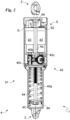
Fig. 2 shows, in scale, a cross-section ofFig. 1 ; and -
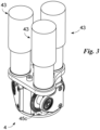
Fig. 3 shows, in scale, an assembly of the anchoring device. - In this document, the measures, values, shapes, and geometric references (such as perpendicularity and parallelism), when associated with words like "about" or other similar terms such as "approximately" or "substantially", are to be understood as except for measurement errors or inaccuracies owing to production and/or manufacturing errors and, above all, except for a slight divergence from the value, measure, shape, or geometric reference with which it is associated. For example, these terms, if associated with a value, preferably indicate a divergence of not more than 10% of the value.
- Furthermore, when used, terms such as "first", "second", "higher", "lower", "main", and "secondary" do not necessarily identify an order, a priority relationship, or a relative position, but can simply be used to more clearly distinguish between the different components.
- The measurements and data provided in this text are to be considered as performed in ICAO International Standard Atmosphere (ISO 2533), unless otherwise indicated. Unless otherwise indicated, as evidenced by the discussions below, it should be understood that terms such as "processing", "computer", "computing", "evaluation", or the like, refer to the action and/or processes of a computer or similar electronic calculation device, which handles and/or processes data represented as physical, such as electronic sizes of logs of a computer system and/or their memories, other data similarly represented as physical quantities inside computer systems, logs or other information storage, transmission or display devices.
- With reference to the figures, the
number 1 indicates, as a whole, the anchoring device according to the invention. - It is suitable for securing a floating object (such as a boat or a buoy) to an anchor structure (floating or attached to the ground) allowing a relative motion between the floating object and the anchor structure.
- The
anchoring device 1 comprises afirst attachment 2 suitable for being secured to the floating object; and asecond attachment 3 suitable for being secured to the anchor structure. - The
first attachment 2 can be secured to the floating object by means of ropes or other suitable connection means, such as chains, metal cables, rods, or shackles (hereinafter called, collectively, ropes). Alternatively, it can be secured to the floating object. - The
second attachment 3 can be secured to the anchor structure by means of ropes. Alternatively, it can be firmly secured to the anchor structure. - Said
attachments - The
anchoring device 1 comprises adamping member 4 for the relative motion between theattachments - The
damping member 4 comprises aslide chamber 41 defining aslide axis 4a; apiston 42 suitable for sliding, along saidaxis 4a, in theslide chamber 41 according to a relative motion between theattachments damper 43 suitable for damping the sliding of thepiston 42 in theslide chamber 41. - The
piston 42 is attached to one ofattachments first attachment 2. - The
slide chamber 41 is attached to anattachment piston 42, and preferably to thesecond attachment 3. - The
slide chamber 41 can define a watertight internal volume. Thepiston 41 has its head inside the internal volume and the stem partially protruding from it through a hole equipped with sealing means. - The sliding of the
piston 42 and, therefore, the position of thepiston 42 defines a contracted configuration for thedamping member 4, wherein the distance between theattachments attachments - The damping
member 4 may, conveniently, compriseelastic means 44 suitable for working in opposition to a variation in the distance between theattachments - The damping
member 4 may comprise at least onekinematic mechanism 45 suitable for kinematically connecting thepiston 42 anddamper 43. Themember 4 conveniently comprises a kinematic mechanism for thedamper 43. - The
kinematic mechanism 45 is a gearing suitable for transforming the rectilinear motion of thepiston 42 into a rotary motion at thedamper 43. - The
kinematic mechanism 45 can be conveniently fixed in relation to the transmission. - It may comprise a
rack 45a extending along theslide axis 4a; and atoothed wheel 45b suitable for sliding along therack 45a. - The
rack 45a can be attached to thepiston 42. - It should be obvious, for a person skilled in the art, how to replace the rack with a worm screw or a ball screw.
- The
toothed wheel 45b can be attached to theslide chamber 41 and can be controlled in rotation by therack 45a. - The
kinematic mechanism 45 can comprise amultiplier 45c suitable for multiplying the rotation speed of the rotor, enabling the transition from low speeds, typical of a wave, to a higher speed motion. - The
damping member 4 preferably comprises at least oneelectric damper 43. Saiddamper 43 is an electric motor suitable for dissipating energy by opposing a reciprocal rotation between stator and rotor. In particular, thedamper 43 is a brushless electric motor. - It should be noted that said electric motor, i.e. the
damper 43, can be used to produce energy by exploiting the sliding of thepiston 42. - The
damper 43 is attached to thechamber 41. - The damping
member 4 conveniently comprisesseveral dampers 43 that can be controlled by said at least onetoothed wheel 45b. More conveniently, the dampingmember 4 comprisesseveral dampers 43 each of which can be controlled by atoothed wheel 45b; and, in particular, threedampers 43 and threetoothed wheels 45b, each of which actuates adamper 43. - An example of a
damping member 4 and, in particular, of theanchoring device 1 is described inEP2705272 in paragraphs, included for reference, [0015]-[0108] and in Figures 1-18, included for reference. - The
anchoring device 1 may comprise at least oneelectrical energy converter 5. Theconverter 5 is suitable for varying the parameters of the electricity output from thedamper 43 allowing the use of an external device and/or thesame device 1. At least oneconverter 5 is located in said internal volume. - The
anchoring device 1 may comprise at least one energy storage battery 6 for the output from theconverter 5 and/or thedamper 43. - The battery 6 is located in said internal volume.
- Optionally, the
anchoring device 1 can comprise 7 connectors suitable for allowing the electrical connection of an external unit to the device. - The connectors are external to the volume and in electrical connection with the battery 6 and/or the
converter 5. - The
anchoring device 1 may comprise acontrol unit 8 for the operation of thesame device 1. - The
control unit 8 may comprise at least one measurement sensor 81 for measuring the sliding of thepiston 42. - In particular, the at least one measurement sensor 81 is suitable for measuring at least one of the following: speed (in module and, conveniently, towards) and acceleration (in module and, conveniently, towards) of the sliding of the
piston 42. - More specifically, the sensor is suitable for measuring speed and acceleration.
- At least one measurement sensor 81 may be suitable for measuring the sliding of the
piston 42 in a direct manner. It can thus carry out a direct measurement of the sliding of thepiston 42 by measuring its movement and/or position (e.g. a variation in position) along theslide axis 4a. The at least one measurement sensor 81 can measure the rotation of thetoothed wheel 45b and/or a variation in distance between thepiston head 42 and a base of theslide chamber 41. - The unit conveniently has a sensor 81 for each
toothed wheel 45b. - As an alternative or addition, the at least one measurement sensor 81 can carry out an indirect measurement of the sliding of the
piston 42 by measuring the operating parameters of thedamper 43. For example, the at least one measurement sensor 81 can measure the rotation speed of the rotor of thedamper 43. - The
control unit 8 may comprise acontrol board 82 of theanchoring device 1. Thecontrol board 82 is in data connection with thedamper 43 and, conveniently, with theconverter 5 and/or battery 6 so as to monitor the production and status of the electrical energy. - The
control board 82 is in data connection with the one or more sensors present in thedevice 1. In particular, thecontrol board 82 is in data connection with the measurement sensor 81. - The
control board 82 may be suitable for varying the damping of thedamper 43 according to the sliding of thepiston 42 measured by the measurement sensor 81. More specifically, theboard 82 varies the damping of thedamper 43 based on the speed and/or acceleration of thepiston 42. Even more specifically, thecontrol board 82 varies the damping of thedamper 43 in accordance with, preferably proportionally to, the speed and/or acceleration of thepiston 42. - It should be noted that in this document the expression "based on" identifies that a variation and, for example, an increase of a first parameter (in this case, the sliding speed of the piston 42) corresponds to any variation (increase or decrease) of the second parameter (in this case, the damping); the expression "in accordance with" identifies that an increase or decrease of a first parameter corresponds, respectively, to an increase or decrease of the second parameter.
- The
control board 82 varies the damping of thedamper 43 by changing the magnetic parameters of the poles at the stator and/or rotor so as to vary the opposition to the rotation of the rotor. More specifically, the board controls 82 variations in parameters such as polarity, magnetic intensity, and electrical load circuit mode. - The
control board 82 is suitable for maintaining the sliding speed of thepiston 42 between a minimum speed and a maximum speed. Therefore, if, for example, the sliding speed of thepiston 42 is greater than the maximum speed, thecontrol board 82 controls an increase in damping and, therefore, thedamper 43 more strongly opposes the sliding of thepiston 42 which slows down. - The minimum speed is substantially less than 0.06 m/s and, more specifically, substantially between 0.06 m/s and 0.01 m/s and, preferably, between 0.05 m/s and 0.03 m/s. It is, conveniently, substantially equal to at least 0.04 m/s.
- The maximum speed is substantially greater than 0.04 m/s and, more specifically, substantially between 0.1 m/s and 0.04 m/s and, preferably, between 0.07 m/s and 0.05 m/s. It is, conveniently, substantially equal to at least 0.06 m/s.
- The
control unit 8 may comprise at least one first force sensor 83 suitable for measuring the force that the floating object applies to thefirst attachment 2. - The
control board 82 can, therefore, based on a variation in force at said first sensor 83, measure variations in external load (for example, due to a wave or wind) on the floating object. - The
control unit 8 may comprise at least onesecond force sensor 84 suitable for measuring the force applied by the anchor structure to thesecond attachment 3. - In the same way, the
control board 82 can, therefore, based on a variation of force at saidsecond sensor 84, measure variations in the external load on the anchor structure due, for example, to movements of the floating object with respect to the anchor structure. - The
control board 82 can vary the damping of thedamper 43 based on and preferably in accordance with, preferably proportionally to, said measurements of the one ormore force sensors 83 and 84. - The
control unit 8 may comprise a monitoring system for thedamper 43 suitable for measuring the parameters of the damper'soperation 43. - The monitoring system may be suitable for measuring the temperature of the
damper 43. - The monitoring system may be suitable for measuring the electrical current parameters (such as amperage and/or voltage) at the output of the
damper 43. Thecontrol unit 8 may comprise at least one environmental sensor set, in data connection with thecontrol board 82, suitable for measuring environmental parameters external to theanchoring device 1. - The
control unit 8 may comprise a first wave motion characterization sensor set. Said first sensor set may comprise one or more first environmental sensors, each of which is suitable for identifying the characteristics of the waves, such as the modulus and direction of the current, the height and frequency of the waves. Based on the data collected by said first sensor set, thecontrol board 82 may vary the damping of thedamper 43. Thecontrol board 82 preferably varies the damping of thedamper 43 in accordance with, preferably proportionally to, the data collected by the first sensor set. - The
control unit 8 may comprise a second sensor set for characterising the water conditions. Said second sensor set may comprise one or more second environmental sensors, each of which is suitable for measuring at least one water parameter that can be chosen from: temperature, clarity, presence of pollutants in the water, salinity, depth, and presence of fish. - The
control unit 8 may comprise a third air characterization sensor set. Said third sensor set may comprise one or more third environmental sensors, each of which is suitable for measuring one or more air parameters such as temperature, exposure to light, presence of pollutants in the air, modulus and wind direction. - It should be noted that the various sensors of said sensor sets are known in and of themselves.
- Finally, the
control unit 8 may comprise a distance gauge. - More specifically, the
control unit 8 may comprise a first distance gauge for gauging the distance between the anchoringdevice 1 and the floating object; and a second distance gauge for gauging the distance between the anchoringdevice 1 and the anchor structure. - The
control unit 8 may comprise a geo-localiser suitable for identifying the position of theanchoring device 1. - The
anchoring device 1 may comprise data connection means suitable for allowing a data exchange, preferably a wireless one (using WI-FI, Bluetooth and LoRa), between thecontrol unit 8 and an external unit suitable for monitoring, thanks to the reception of the parameters collected by thecontrol unit 8, the operation of thedevice 1. - The operation of the
anchoring device 1 described above in a structural sense, is as follows. - To begin with, the
anchoring device 1 is secured, through thefirst attachment 2, to the floating object (e.g. a boat or a vessel) and, through thesecond attachment 3, to an anchor structure. - When, due to the wave motion, there is a relative motion between the floating object and the anchor structure that, by moving the
attachments piston 42 along theslide axis 4a, then, thedamper 43 is actuated to attenuate the motion between the floating object and the anchor structure. - More specifically, the motion of the
piston 42 causes therack 45a to slide, resulting in a rotation of thetoothed wheel 45b that, through a kinematic connection mechanism, activates thedamper 43, causing the rotor to rotate. - This rotation of the rotor, due to the poles present on the stator, results in both a slowing down of the sliding of the piston, attenuating the motion between the floating object and the anchor structure, and a production of electrical energy that can be used to operate the
device 1 and/or to supply an external device. - Where the
control board 82, thanks to the measurement sensor 81, measures the speed of thepiston 42 as higher than the maximum speed or lower than the minimum speed, thesame control board 82 controls, respectively, an increase or a decrease of the damping of thedamper 43 bringing the speed of thepiston 42 within the desired range. - The
anchoring device 1 according to the invention achieves important advantages. In fact, thanks to the measuring sensor 81 and, therefore, thecontrol board 82, it is able to monitor the operation of thedamper 43. In particular, theanchoring device 1, by acting on the damping, is able to vary the sliding speed of thepiston 42 and, consequently, to have a basic adaptive behaviour based on the sea conditions. - In fact, by varying the sliding speed of the
piston 42 based on the sliding of thepiston 42 and, therefore, based on the wave motion, the device can easily adapt the speed of the damper (i.e. of the rotor) keeping it within a range of maximum efficiency of electricity production. - In addition, this capacity allows the
anchoring device 1 to smoothly oscillate regardless of the state of the sea and wind. - It should be noted that this aspect is further accentuated by the presence of
force sensors 83 and 84 that, by providing additional information to thecontrol board 2, allow a more optimal control of theanchoring device 1 and, therefore, of its oscillations. - One advantage owes to the presence of the data connection means that, by sending the data collected by the
control unit 8 to an external unit, allow to remotely monitor the operation of the anchoring device 1 (allowing, for example, a preventive maintenance) and/or allow to know, for example, the presence and status of a floating object anchored to thedevice 1 or a trend history of the wave motion, the state of the sea, etc. - The invention is subject to variations falling within the scope of the inventive concept defined by the claims. In this context all the details may be replaced with equivalent elements and the materials, shapes and dimensions may be as desired.
piston 42 and, therefore, based on the wave motion, the device can easily adapt the speed of the damper (i.e. of the rotor) keeping it within a range of maximum efficiency of electricity production. - In addition, this capacity allows the
anchoring device 1 to smoothly oscillate regardless of the state of the sea and wind. - It should be noted that this aspect is further accentuated by the presence of
force sensors 83 and 84 that, by providing additional information to thecontrol board 2, allow a more optimal control of theanchoring device 1 and, therefore, of its oscillations. - One advantage owes to the presence of the data connection means that, by sending the data collected by the
control unit 8 to an external unit, allow to remotely monitor the operation of the anchoring device 1 (allowing, for example, a preventive maintenance) and/or allow to know, for example, the presence and status of a floating object anchored to thedevice 1 or a trend history of the wave motion, the state of the sea, etc. - The invention is subject to variations falling within the scope of the inventive concept defined by the claims. In this context all the details may be replaced with equivalent elements and the materials, shapes and dimensions may be as desired.
Claims (10)
- An anchoring device (1) for anchoring a floating object to an anchor structure comprising:- a first attachment (2) suitable for being secured to said floating object;- a second attachment (3) suitable for being secured to said anchor structure;- a damping member (4) for damping the relative motion between said attachments (2, 3) and suitable for securing said first attachment (2) to said second attachment (3) and comprising∘ a slide chamber (41),∘ a piston (42) suitable for sliding in said slide chamber (41) according to a relative motion between said attachments (2, 3) and∘ at least one damper (43) suitable for damping the sliding of said piston (42) in said slide chamber (41); and- a control unit (8) for said anchoring device (1) comprisingcharacterised in that∘ a measurement sensor (81) for measuring at least one of speed and acceleration of said piston (42); and∘ a control board (82) suitable for varying the damping of said damper (43) according to said sliding of said piston (42) detected by said measurement sensor (81);- said damper (43) is an electric motor used to produce energy by exploiting the sliding of the piston (42) and suitable for dissipating energy by opposing a reciprocal rotation between stator and rotor; and- said control board (82) varies the damping of said damper (43) by changing the magnetic parameters of the poles at the stator and/or rotor so as to vary the opposition to the rotation of the rotor.
- The anchoring device (1) according to claim 1, wherein said control board (82) varies the damping of said damper (43) according to said least one of speed and acceleration of said piston (42).
- The anchoring device (1) according to at least one of the preceding claims, wherein said damping member (4) comprises at least one kinematic mechanism (45) suitable for kinematically connecting said piston (42) to said damper (43); said kinematic mechanism (45) comprises a rack (45a), a toothed wheel (45b) suitable for sliding along said rack (45a) when said piston (42) slides in said slide chamber (41); and wherein said measurement sensor (81) measures the rotations of said toothed wheel to calculate said least one of speed and acceleration of said piston (42).
- The anchoring device (1) according to at least one of the preceding claims,
wherein said piston (42) controls the rotation of said rotor when said piston (42) slides in said slide chamber (41) and wherein said measurement sensor (81) measures the rotations of said rotor in order to calculate said sliding of said piston (42). - The anchoring device (1) according to at least one of the preceding claims, wherein said control board (82) is suitable for maintaining the sliding speed of said piston (42) between a minimum speed and a maximum speed; wherein said minimum speed is substantially between 0.05 m/s and 0.03 m/s and wherein said maximum speed is substantially between 0.07 m/s and 0.05 m/s.
- The anchoring device (1) according to at least one of the preceding claims, comprising data connection means suitable for allowing data exchange between said control unit (8) and an external monitoring unit of said anchoring device (1).
- The anchoring device (1) according to at least one of the preceding claims, wherein said control unit (8) comprises at least one of a first force sensor (83) suitable for measuring a force applied by said floating object to said first attachment (2) and a second force sensor (84) suitable for measuring the force applied by said anchor structure to said second attachment (3).
- The anchoring device (1) according to at least one of the preceding claims, wherein said control unit (8) comprises a first sensor set for characterizing the wave motion, which is suitable for measuring at least one of the following: the modulus of the current, the direction of said current, the height of the waves, and the frequency of said waves.
- The anchoring device (1) according to at least one of the preceding claims, wherein said control unit (8) comprises a second sensor set for characterizing the conditions of the water, which is suitable for measuring at least one of the following: the temperature of said water, the clarity of said water, the presence of pollutants in said water, its salinity, the depth of said water and the presence of fish in said water.
- The anchoring device (1) according to at least one of the preceding claims, wherein said control unit (8) comprises a third sensor set for characterizing the air, which is suitable for measuring at least one of the following: the temperature of said air, the light exposure of said anchoring device (1), the presence of pollutants in said air, the modulus and direction of the wind.
Applications Claiming Priority (2)
| Application Number | Priority Date | Filing Date | Title |
|---|---|---|---|
| IT102018000010258A IT201800010258A1 (en) | 2018-11-12 | 2018-11-12 | ANCHORING DEVICE |
| PCT/IB2019/059655 WO2020100003A1 (en) | 2018-11-12 | 2019-11-11 | Anchoring device |
Publications (3)
| Publication Number | Publication Date |
|---|---|
| EP3880550A1 EP3880550A1 (en) | 2021-09-22 |
| EP3880550C0 EP3880550C0 (en) | 2024-08-21 |
| EP3880550B1 true EP3880550B1 (en) | 2024-08-21 |
Family
ID=67875835
Family Applications (1)
| Application Number | Title | Priority Date | Filing Date |
|---|---|---|---|
| EP19813653.3A Active EP3880550B1 (en) | 2018-11-12 | 2019-11-11 | Anchoring device |
Country Status (7)
| Country | Link |
|---|---|
| US (1) | US11541966B2 (en) |
| EP (1) | EP3880550B1 (en) |
| CN (1) | CN113039120A (en) |
| AU (1) | AU2019378179B2 (en) |
| ES (1) | ES2989431T3 (en) |
| IT (1) | IT201800010258A1 (en) |
| WO (1) | WO2020100003A1 (en) |
Families Citing this family (3)
| Publication number | Priority date | Publication date | Assignee | Title |
|---|---|---|---|---|
| US12545370B2 (en) * | 2018-11-12 | 2026-02-10 | Seares S.R.L. | Anchoring device |
| CN114162263B (en) * | 2021-12-17 | 2023-01-06 | 浙江大学 | A floating wind turbine mooring system and control method based on active control |
| IT202300006234A1 (en) * | 2023-03-30 | 2024-09-30 | Seares S R L | ANCHORING DEVICE |
Citations (1)
| Publication number | Priority date | Publication date | Assignee | Title |
|---|---|---|---|---|
| EP0142996A2 (en) * | 1983-11-23 | 1985-05-29 | Vickers Plc | Mooring boom |
Family Cites Families (11)
| Publication number | Priority date | Publication date | Assignee | Title |
|---|---|---|---|---|
| DE2848339C2 (en) * | 1978-11-08 | 1984-07-05 | Feinmechanische Werke Mainz Gmbh, 6500 Mainz | Active, mechanical-hydraulic controller |
| US5657840A (en) * | 1986-06-05 | 1997-08-19 | Lizell; Magnus B. | Method and apparatus for absorbing mechanical shock |
| US6193029B1 (en) * | 1997-07-08 | 2001-02-27 | Active Control Experts, Inc. | Damper and valve |
| EP2029890B1 (en) * | 2006-05-30 | 2016-01-27 | Triple X Energy Inc. | Wave energy converter |
| JP5040775B2 (en) * | 2008-03-31 | 2012-10-03 | トヨタ自動車株式会社 | shock absorber |
| US8614518B2 (en) * | 2009-10-14 | 2013-12-24 | GM Global Technology Operations LLC | Self-powered vehicle sensor systems |
| ITPI20110052A1 (en) | 2011-05-03 | 2012-11-04 | Giorgio Cuce | HYDRAULIC DAMPING STRUCTURE |
| DE102012007120A1 (en) * | 2012-04-05 | 2013-10-10 | Audi Ag | Electric damper |
| PL2861888T3 (en) * | 2012-06-15 | 2019-10-31 | Faringosi Hinges Srl | Damper for hinges |
| US20180001968A1 (en) * | 2015-01-23 | 2018-01-04 | InterOcean Systems, LLC | Release Apparatus and Method Of Manufacturing A Release Apparatus |
| DE102016225626A1 (en) * | 2016-12-20 | 2018-06-21 | Bayerische Motoren Werke Aktiengesellschaft | Damper system for suspension of a vehicle, method of operating a damper system and vehicle having a damper system |
-
2018
- 2018-11-12 IT IT102018000010258A patent/IT201800010258A1/en unknown
-
2019
- 2019-11-11 US US17/292,611 patent/US11541966B2/en active Active
- 2019-11-11 EP EP19813653.3A patent/EP3880550B1/en active Active
- 2019-11-11 WO PCT/IB2019/059655 patent/WO2020100003A1/en not_active Ceased
- 2019-11-11 ES ES19813653T patent/ES2989431T3/en active Active
- 2019-11-11 CN CN201980074572.5A patent/CN113039120A/en active Pending
- 2019-11-11 AU AU2019378179A patent/AU2019378179B2/en active Active
Patent Citations (1)
| Publication number | Priority date | Publication date | Assignee | Title |
|---|---|---|---|---|
| EP0142996A2 (en) * | 1983-11-23 | 1985-05-29 | Vickers Plc | Mooring boom |
Also Published As
| Publication number | Publication date |
|---|---|
| AU2019378179A1 (en) | 2021-06-03 |
| EP3880550C0 (en) | 2024-08-21 |
| CN113039120A (en) | 2021-06-25 |
| IT201800010258A1 (en) | 2020-05-12 |
| US11541966B2 (en) | 2023-01-03 |
| US20220001959A1 (en) | 2022-01-06 |
| EP3880550A1 (en) | 2021-09-22 |
| WO2020100003A1 (en) | 2020-05-22 |
| ES2989431T3 (en) | 2024-11-26 |
| AU2019378179B2 (en) | 2025-12-18 |
Similar Documents
| Publication | Publication Date | Title |
|---|---|---|
| US11541966B2 (en) | Anchoring device | |
| US12545370B2 (en) | Anchoring device | |
| CA3045003C (en) | Control system for a floating wind turbine structure | |
| US9884670B2 (en) | Air-based-deployment-compatible underwater vehicle configured to perform vertical profiling and, during information transmission, perform motion stabilization at a water surface, and associated methods | |
| EP3020960B1 (en) | Floating-body type wind turbine power generating apparatus and operation method of the same | |
| KR20150062238A (en) | apparatus for measuring added resistance in waves | |
| JP2001515587A (en) | Mooring type water quality inspection device | |
| Huang et al. | Numerical design study of multipoint mooring systems for the floating wave energy converter in deep water with a sloping bottom | |
| EP2841769A1 (en) | Wind turbine on a floating support stabilised by a raised anchoring system | |
| CN114207277A (en) | Control system for stabilizing a floating wind turbine | |
| Sergiienko et al. | Three-tether axisymmetric wave energy converter: Estimation of energy delivery | |
| Durand et al. | Experimental validation of the performances of the SEAREV wave energy converter with real time latching control | |
| CN113911289B (en) | Floating fan semi-submersible platform operation period monitoring method | |
| CN113982860A (en) | Method for monitoring operation period of floating type fan column type platform | |
| KR101304931B1 (en) | Submersible rudder force dynamometer | |
| CN111605674A (en) | Three-degree-of-freedom swing compensation device applied to inland waterway measurement system | |
| KR102133368B1 (en) | Unmanned dynamic buoy system for measuring precise marine location, Method thereof, and Computer readable storage medium | |
| Bachynski et al. | Hydrodynamic modeling of tension leg platform wind turbines | |
| CN118449394A (en) | Load self-regulating nano friction power generation buoy and method | |
| KR101312555B1 (en) | Method for detecting the movement condition of a vessel with regard to a rolling movement resonance | |
| Brown et al. | Phase-resolved heave plate dynamics for wave energy converters | |
| Krata | Linear characteristics of the sloshing phenomenon for the purpose of on-board ship's stability assessment | |
| EP4442552A1 (en) | Anchoring device | |
| Gryazin et al. | An advanced electric power generator for offshore autonomous stations | |
| RU2669251C1 (en) | Measuring system for determining parameters of water medium in course of ship (options) |
Legal Events
| Date | Code | Title | Description |
|---|---|---|---|
| STAA | Information on the status of an ep patent application or granted ep patent |
Free format text: STATUS: UNKNOWN |
|
| STAA | Information on the status of an ep patent application or granted ep patent |
Free format text: STATUS: THE INTERNATIONAL PUBLICATION HAS BEEN MADE |
|
| PUAI | Public reference made under article 153(3) epc to a published international application that has entered the european phase |
Free format text: ORIGINAL CODE: 0009012 |
|
| STAA | Information on the status of an ep patent application or granted ep patent |
Free format text: STATUS: REQUEST FOR EXAMINATION WAS MADE |
|
| 17P | Request for examination filed |
Effective date: 20210517 |
|
| AK | Designated contracting states |
Kind code of ref document: A1 Designated state(s): AL AT BE BG CH CY CZ DE DK EE ES FI FR GB GR HR HU IE IS IT LI LT LU LV MC MK MT NL NO PL PT RO RS SE SI SK SM TR |
|
| DAV | Request for validation of the european patent (deleted) | ||
| DAX | Request for extension of the european patent (deleted) | ||
| STAA | Information on the status of an ep patent application or granted ep patent |
Free format text: STATUS: EXAMINATION IS IN PROGRESS |
|
| 17Q | First examination report despatched |
Effective date: 20230102 |
|
| GRAP | Despatch of communication of intention to grant a patent |
Free format text: ORIGINAL CODE: EPIDOSNIGR1 |
|
| STAA | Information on the status of an ep patent application or granted ep patent |
Free format text: STATUS: GRANT OF PATENT IS INTENDED |
|
| INTG | Intention to grant announced |
Effective date: 20240318 |
|
| GRAS | Grant fee paid |
Free format text: ORIGINAL CODE: EPIDOSNIGR3 |
|
| GRAA | (expected) grant |
Free format text: ORIGINAL CODE: 0009210 |
|
| STAA | Information on the status of an ep patent application or granted ep patent |
Free format text: STATUS: THE PATENT HAS BEEN GRANTED |
|
| AK | Designated contracting states |
Kind code of ref document: B1 Designated state(s): AL AT BE BG CH CY CZ DE DK EE ES FI FR GB GR HR HU IE IS IT LI LT LU LV MC MK MT NL NO PL PT RO RS SE SI SK SM TR |
|
| REG | Reference to a national code |
Ref country code: GB Ref legal event code: FG4D |
|
| REG | Reference to a national code |
Ref country code: CH Ref legal event code: EP |
|
| REG | Reference to a national code |
Ref country code: IE Ref legal event code: FG4D |
|
| REG | Reference to a national code |
Ref country code: DE Ref legal event code: R096 Ref document number: 602019057518 Country of ref document: DE |
|
| U01 | Request for unitary effect filed |
Effective date: 20240920 |
|
| U07 | Unitary effect registered |
Designated state(s): AT BE BG DE DK EE FI FR IT LT LU LV MT NL PT RO SE SI Effective date: 20241014 |
|
| REG | Reference to a national code |
Ref country code: ES Ref legal event code: FG2A Ref document number: 2989431 Country of ref document: ES Kind code of ref document: T3 Effective date: 20241126 |
|
| U20 | Renewal fee for the european patent with unitary effect paid |
Year of fee payment: 6 Effective date: 20241128 |
|
| PG25 | Lapsed in a contracting state [announced via postgrant information from national office to epo] |
Ref country code: NO Free format text: LAPSE BECAUSE OF FAILURE TO SUBMIT A TRANSLATION OF THE DESCRIPTION OR TO PAY THE FEE WITHIN THE PRESCRIBED TIME-LIMIT Effective date: 20241121 |
|
| PG25 | Lapsed in a contracting state [announced via postgrant information from national office to epo] |
Ref country code: GR Free format text: LAPSE BECAUSE OF FAILURE TO SUBMIT A TRANSLATION OF THE DESCRIPTION OR TO PAY THE FEE WITHIN THE PRESCRIBED TIME-LIMIT Effective date: 20241122 Ref country code: PL Free format text: LAPSE BECAUSE OF FAILURE TO SUBMIT A TRANSLATION OF THE DESCRIPTION OR TO PAY THE FEE WITHIN THE PRESCRIBED TIME-LIMIT Effective date: 20240821 |
|
| PG25 | Lapsed in a contracting state [announced via postgrant information from national office to epo] |
Ref country code: IS Free format text: LAPSE BECAUSE OF FAILURE TO SUBMIT A TRANSLATION OF THE DESCRIPTION OR TO PAY THE FEE WITHIN THE PRESCRIBED TIME-LIMIT Effective date: 20241221 |
|
| PG25 | Lapsed in a contracting state [announced via postgrant information from national office to epo] |
Ref country code: HR Free format text: LAPSE BECAUSE OF FAILURE TO SUBMIT A TRANSLATION OF THE DESCRIPTION OR TO PAY THE FEE WITHIN THE PRESCRIBED TIME-LIMIT Effective date: 20240821 |
|
| PG25 | Lapsed in a contracting state [announced via postgrant information from national office to epo] |
Ref country code: RS Free format text: LAPSE BECAUSE OF FAILURE TO SUBMIT A TRANSLATION OF THE DESCRIPTION OR TO PAY THE FEE WITHIN THE PRESCRIBED TIME-LIMIT Effective date: 20241121 |
|
| PG25 | Lapsed in a contracting state [announced via postgrant information from national office to epo] |
Ref country code: RS Free format text: LAPSE BECAUSE OF FAILURE TO SUBMIT A TRANSLATION OF THE DESCRIPTION OR TO PAY THE FEE WITHIN THE PRESCRIBED TIME-LIMIT Effective date: 20241121 Ref country code: PL Free format text: LAPSE BECAUSE OF FAILURE TO SUBMIT A TRANSLATION OF THE DESCRIPTION OR TO PAY THE FEE WITHIN THE PRESCRIBED TIME-LIMIT Effective date: 20240821 Ref country code: NO Free format text: LAPSE BECAUSE OF FAILURE TO SUBMIT A TRANSLATION OF THE DESCRIPTION OR TO PAY THE FEE WITHIN THE PRESCRIBED TIME-LIMIT Effective date: 20241121 Ref country code: IS Free format text: LAPSE BECAUSE OF FAILURE TO SUBMIT A TRANSLATION OF THE DESCRIPTION OR TO PAY THE FEE WITHIN THE PRESCRIBED TIME-LIMIT Effective date: 20241221 Ref country code: HR Free format text: LAPSE BECAUSE OF FAILURE TO SUBMIT A TRANSLATION OF THE DESCRIPTION OR TO PAY THE FEE WITHIN THE PRESCRIBED TIME-LIMIT Effective date: 20240821 Ref country code: GR Free format text: LAPSE BECAUSE OF FAILURE TO SUBMIT A TRANSLATION OF THE DESCRIPTION OR TO PAY THE FEE WITHIN THE PRESCRIBED TIME-LIMIT Effective date: 20241122 |
|
| PG25 | Lapsed in a contracting state [announced via postgrant information from national office to epo] |
Ref country code: SM Free format text: LAPSE BECAUSE OF FAILURE TO SUBMIT A TRANSLATION OF THE DESCRIPTION OR TO PAY THE FEE WITHIN THE PRESCRIBED TIME-LIMIT Effective date: 20240821 |
|
| PG25 | Lapsed in a contracting state [announced via postgrant information from national office to epo] |
Ref country code: CZ Free format text: LAPSE BECAUSE OF FAILURE TO SUBMIT A TRANSLATION OF THE DESCRIPTION OR TO PAY THE FEE WITHIN THE PRESCRIBED TIME-LIMIT Effective date: 20240821 |
|
| PG25 | Lapsed in a contracting state [announced via postgrant information from national office to epo] |
Ref country code: SK Free format text: LAPSE BECAUSE OF FAILURE TO SUBMIT A TRANSLATION OF THE DESCRIPTION OR TO PAY THE FEE WITHIN THE PRESCRIBED TIME-LIMIT Effective date: 20240821 |
|
| PLBE | No opposition filed within time limit |
Free format text: ORIGINAL CODE: 0009261 |
|
| STAA | Information on the status of an ep patent application or granted ep patent |
Free format text: STATUS: NO OPPOSITION FILED WITHIN TIME LIMIT |
|
| REG | Reference to a national code |
Ref country code: CH Ref legal event code: PL |
|
| PG25 | Lapsed in a contracting state [announced via postgrant information from national office to epo] |
Ref country code: MC Free format text: LAPSE BECAUSE OF FAILURE TO SUBMIT A TRANSLATION OF THE DESCRIPTION OR TO PAY THE FEE WITHIN THE PRESCRIBED TIME-LIMIT Effective date: 20240821 |
|
| REG | Reference to a national code |
Ref country code: CH Ref legal event code: PL |
|
| PG25 | Lapsed in a contracting state [announced via postgrant information from national office to epo] |
Ref country code: CH Free format text: LAPSE BECAUSE OF NON-PAYMENT OF DUE FEES Effective date: 20241130 |
|
| 26N | No opposition filed |
Effective date: 20250522 |
|
| PG25 | Lapsed in a contracting state [announced via postgrant information from national office to epo] |
Ref country code: IE Free format text: LAPSE BECAUSE OF NON-PAYMENT OF DUE FEES Effective date: 20241111 |
|
| U20 | Renewal fee for the european patent with unitary effect paid |
Year of fee payment: 7 Effective date: 20251031 |
|
| PGFP | Annual fee paid to national office [announced via postgrant information from national office to epo] |
Ref country code: GB Payment date: 20251120 Year of fee payment: 7 |
|
| PGFP | Annual fee paid to national office [announced via postgrant information from national office to epo] |
Ref country code: ES Payment date: 20251216 Year of fee payment: 7 |
|
| PG25 | Lapsed in a contracting state [announced via postgrant information from national office to epo] |
Ref country code: HU Free format text: LAPSE BECAUSE OF FAILURE TO SUBMIT A TRANSLATION OF THE DESCRIPTION OR TO PAY THE FEE WITHIN THE PRESCRIBED TIME-LIMIT; INVALID AB INITIO Effective date: 20191111 |
|
| PG25 | Lapsed in a contracting state [announced via postgrant information from national office to epo] |
Ref country code: CY Free format text: LAPSE BECAUSE OF FAILURE TO SUBMIT A TRANSLATION OF THE DESCRIPTION OR TO PAY THE FEE WITHIN THE PRESCRIBED TIME-LIMIT; INVALID AB INITIO Effective date: 20191111 |