EP3880544B1 - Segmented wheel - Google Patents
Segmented wheel Download PDFInfo
- Publication number
- EP3880544B1 EP3880544B1 EP19779982.8A EP19779982A EP3880544B1 EP 3880544 B1 EP3880544 B1 EP 3880544B1 EP 19779982 A EP19779982 A EP 19779982A EP 3880544 B1 EP3880544 B1 EP 3880544B1
- Authority
- EP
- European Patent Office
- Prior art keywords
- wheel
- segments
- segment
- rim portion
- debris
- Prior art date
- Legal status (The legal status is an assumption and is not a legal conclusion. Google has not performed a legal analysis and makes no representation as to the accuracy of the status listed.)
- Active
Links
Images



Classifications
-
- B—PERFORMING OPERATIONS; TRANSPORTING
- B62—LAND VEHICLES FOR TRAVELLING OTHERWISE THAN ON RAILS
- B62D—MOTOR VEHICLES; TRAILERS
- B62D55/00—Endless track vehicles
- B62D55/08—Endless track units; Parts thereof
- B62D55/14—Arrangement, location, or adaptation of rollers
-
- B—PERFORMING OPERATIONS; TRANSPORTING
- B62—LAND VEHICLES FOR TRAVELLING OTHERWISE THAN ON RAILS
- B62D—MOTOR VEHICLES; TRAILERS
- B62D55/00—Endless track vehicles
- B62D55/08—Endless track units; Parts thereof
- B62D55/12—Arrangement, location, or adaptation of driving sprockets
Definitions
- the present invention relates to wheels for use with endless track systems on vehicles.
- endless track systems used to propel agricultural machines for example tractors or combine harvesters.
- Endless track systems are frequently used on agricultural vehicles where increased levels of traction are required or where it is desired to reduce the point load on the ground i.e. to reduce surface compaction of soil.
- Endless track systems employ a number of wheels around which a rubber or metallic track system runs. Some of the aforementioned wheels are unpowered for example idler wheels and other wheels are driven by the prime mover of the vehicle i.e drive wheels.
- the drive wheels of an endless tracked system are larger than the idler wheels.
- the drive wheels are provided with an elastomeric surface around the outer edge of the drive wheel which increases friction with the inside or running surface of the endless track and also prevent damage or excessive wear and reduction in noise of the overall system.
- Some of the wheels of endless track systems are of such a diameter that the application of the elastomeric surface requires the entire wheel to be enclosed in a mould or else require other large expensive tooling to apply the elastomeric or rubber surface.
- Endless track systems either use a positive drive method or friction drive method as the primary means to transfer the torque from the drive wheel/sprocket to the belt.
- the positive drive method physically engages the inner-side of the tracks at guide blocks.
- the friction drive track system typically comprises a drive wheel or wheels that have an elastomeric material bonded and/or attached to the outside perimeter of the wheel.
- This elastomeric material allows for better friction characteristics between the drive wheel and the track carcass.
- formed steel drive wheels often require an outer lip, the outer lip can often trap dirt and debris which is unfavourable.
- the objective of this invention is to provide a solution to one or more of the above mentioned problems.
- GB 2 435 867 A discloses a drive wheel for an endless track in which a number of circumferentially spaced drive members are bolted to a peripheral region of a radially extending hub.
- Each drive member has first and second supports which locate on opposing sides of the hub and are shaped to define between them a locating lug receipt well for receiving the locating lugs of the track.
- Radially outer faces of the first and second supports are provided with a rubber friction member that engages with an inner surface of the track.
- a wheel for use with an endless track system comprises at least three segments, each of the segments is substantially identical wherein each of the segments comprises a support portion, a circumferential flange and a rim portion wherein the rim portion is affixed to an outer face of the circumferential flange and wherein the segments are configured to attach to each other thereby forming the wheel.
- each of the segments can be processed individually therefore reducing the overall size of tooling required to apply an elastomeric coating to an outer face of the segment. This reduces manufacturing costs. Furthermore, by constructing a wheel from segments, localised thickening of the segments can be included more easily.
- the rim portion may be an elastomer.
- An elastomeric rim portion reduces damage to an endless track and dampens the noise of the system.
- the rim portion may be bonded to the outer face.
- Bonding the rim portion to the outer face provides a durable connection of the rim portion to the rest of the wheel.
- each segment may further comprise an inner edge, the inner edge may be configured for attachment to a hub portion or an axle flange.
- the inner edge may be bolted to the hub portion or axle flange.
- the assembled wheel may be removably attached to an axle using conventional fasteners i.e. bolts.
- each segment may be configured to be bolted to each adjacent segment.
- each segment includes corresponding interlocking formations configured to join each segment to an adjacent segment.
- interlocking formations removes the requirement for further componentry to be used to attach the segments to each other, however it will be understood to further strengthen the joint or interface between adjacent segments.
- Conventional fasteners may be used in addition to the interlocking formations.
- each segment may further comprise an inner face of the circumferential flange, and wherein the inner face is provided with a debris ejection formation at the interface of two segments.
- Debris ejectors assist in clearing the wheel of debris during use and therefore improve the durability of the endless track system and its efficiency by keeping the system clear of the debris.
- the rim portion may further comprise an exterior face for contact with an endless track, wherein the exterior face comprises a plurality of grooves the grooves for ejecting debris caught between the wheel and endless track.
- the plurality of grooves may be arranged such that a groove at the interface of two segments bridges the adjacent segments uninterrupted.
- the grooves can function as intended and allow for each segment of the wheel to be identical, thus reducing part cost through increased production volume of a given part.
- a wheel 10 for an endless track system In this embodiment the wheel 10 has three segments 12.
- the wheel 10 comprises three segments 12. Each of the segments 12 is substantially identical.
- Each segment 12 comprises a support portion 14 and a rim portion 18.
- the support portion 14 is an annular sector in shape having a central connection portion 20, a body portion 22, an outer portion 24 and a circumferential flange 16.
- the central connection portion 20 is configured for connection to an axle flange or the like by any suitable means, for example bolts inserted through bolt holes 26 and attached to an axle flange or hub (not shown).
- the connection portion 20 may be connected to a hub disc (not shown) which is in turn attached to an axle.
- the body portion 22 extends radially outward from the central connection portion 20 becoming the outer portion 24.
- the body portion 22 is substantially flat, in other examples the body portion 22 may include localised thickening of material for strengthening and/or apertures to reduce the overall segment 12 weight.
- the circumferential flange 16 comprises an inner face 28, an outer face 30 and an interface portion 32 at each end of the circumferential flange 16.
- the circumferential flange 16 extends seamlessly from the outer portion 24 substantially perpendicularly to the plane of the body portion 22.
- the outer face 30 provides a surface for attachment of the rim portion 18 and faces away from the axis of rotation of the wheel 10.
- Each interface portion 32 abuts with the interface portion 32 of an adjacent segment 12 when the segments 12 are connected to form the wheel 10.
- the interface portion 32 in this specific example includes corresponding chamfered faces 34 and fastener holes 36 for bolts.
- the interface portion 32 may include any suitable means for securing adjacent segments 12 together for example welding, riveting or adhesive bonding.
- the inner face 28 faces toward the axis of rotation of the wheel 10.
- the inner face 28 includes debris ejectors 38.
- the debris ejectors 38 are configured to urge debris collecting on the inner face 28, away from the plane of the body portion 22 thereby helping to reduce debris accumulation on the wheel 10.
- the debris ejectors 38 bridge the interface portion 32 of the circumferential flange 16, however in other examples the debris ejectors 38 may be provided on the inner face 28 distanced from the interface portions 32 or may be omitted entirely.
- the debris ejectors 38 provide for localised thickening and strengthening of the circumferential flange 16 thereby strengthening the fastener holes 36 and therefore the arrangement of the segments 12 when connected to form the wheel 10.
- the support portion 14 and the circumferential flange 16 in this specific example are a single metallic component, for example pressed mild steel, however they may be two separate components which are joined together or a single spun or moulded or pressed component, it will be understood that any suitable forming process may be used.
- the rim portion 18 is of an elastomeric material and is attached using any suitable means to the outer face 30 of the circumferential flange 16.
- the wheel 10 is mounted to a vehicle, for example an agricultural tractor, the wheel 10 either supporting and/or driving an endless belt system to propel the vehicle.
- the rim portion 18 contacts the inside face of an endless track (not shown).
- the moulds which may be used to apply the rim portion 18 to the support portion 14 can be much smaller than the mould size that would be required to apply a rim portion 18 to a wheel that was not constructed of sub segments.
- a wheel 110 for an endless track system comprises five segments 112 and a hub portion 113, which is also known as a hub disc.
- the hub portion 113 is generally disc shaped and comprises are number of fastener holes which are suitable for the attachment of the segments 112 to the disc.
- the hub portion 113 includes a central flange 170 which is provided for the attachment of the hub portion 113 and thereby the wheel 110 to the axle (not shown) of a vehicle.
- Each of the five segments 112 is substantially identical and each comprises a support portion 114 and a rim portion 118. Although five segments 112 are shown in this embodiment it will be understood that less or more segments may be used depending on the application and preferred construction of the wheel 110.
- the support portions 114 comprise a central connection portion 120, a body portion 122, an outer portion 124 and a circumferential flange 116.
- the central connection portion 120 is configured for connection to the hub portion 113 by any suitable means, for example bolts 125 inserted through bolt holes 126. Washers 127 may be held under the head of the bolts 125 in a conventional manner.
- the body portion 122 extends radially outward from the central connection portion 120 terminating at the outer portion 124 thereby forming an arcuate member.
- the body portion 122 includes localised thickening 129 of material for strengthening in proximity to the bolt holes 126.
- the circumferential flange 116 comprises an inner face 128, an outer face 130 and an interface portion 132 at each end of the circumferential flange 116.
- the circumferential flange 116 is in this embodiment an extension of the outer portion 124 extending substantially perpendicularly to the plane of the body portion 122 and outer portion 124.
- the outer face 130 provides a surface for attachment of the rim portion 118 and is orientated to face away from the axis of rotation of the wheel 110.
- Each interface portion 132 in this specific example include corresponding, interlocking formations 150.
- the interlocking formations 150 are best seen individually in figures 9 and 10 and in figure 6 which shows the interlocking formations 150 in an engaged position. In the engaged position the tongue 152 of one segment 112 interlocks with the groove 154 to secure adjacent segments 112 relative to each other.
- the inner face 128 may include debris ejectors 138.
- the debris ejectors 138 are configured to propel debris that may collect on the inner face 128, out of the wheel 110 and away from a vehicle, thereby helping to reduce debris accumulation on the wheel 110.
- the debris ejectors 138 are formed from two parts, one on either side of the interface portion 132 of the circumferential flange 116, however in other examples the debris ejectors 138 may be provided on the inner face 128 away from the interface portions 132 or may be omitted entirely.
- the debris ejectors 138 are formed from localised thickening of the circumferential flange 116 and also act to strengthen the interface between adjacent segments 112.
- the support portion 114 and the circumferential flange 116 are in this embodiment a single component of pressed mild steel, however they may be two separate components which are joined together or a single spun or moulded or pressed component, it will be understood that any suitable forming process may be used to manufacture the support portions 114.
- the rim portion 118 is affixed to the outer surface 130 by any suitable means, for example by over moulding or bonding. Generally the rim portion 118 is constructed of an elastomeric material.
- the rim portion 118 includes a tread pattern 160 which may be for example moulded or cut into the rim portion 118.
- the tread pattern 160 comprises a regular series of troughs 162 and peaks 164.
- the tread pattern 160 is arranged such that debris that may be caught between the rim portion 118 and a track when the wheel 110 is in use, is ejected so as to avoid damage to the wheel 110 and a track which rides upon the said wheel 110.
- the tread pattern 160 is so arranged that when the segments 114 are attached to one another to form a wheel 110, the tread pattern 160 continues uninterrupted over the interfaces of adjacent segments 114, this is best seen in figure 6 at reference 166. Putting it another way, the tread pattern 160 can be profiled to be continuous once the segments 112 are assembled into a wheel 110.
Landscapes
- Engineering & Computer Science (AREA)
- Chemical & Material Sciences (AREA)
- Combustion & Propulsion (AREA)
- Transportation (AREA)
- Mechanical Engineering (AREA)
- Tires In General (AREA)
- Moulds For Moulding Plastics Or The Like (AREA)
Description
- The present invention relates to wheels for use with endless track systems on vehicles. In particular, endless track systems used to propel agricultural machines for example tractors or combine harvesters.
- Endless track systems are frequently used on agricultural vehicles where increased levels of traction are required or where it is desired to reduce the point load on the ground i.e. to reduce surface compaction of soil.
- Endless track systems employ a number of wheels around which a rubber or metallic track system runs. Some of the aforementioned wheels are unpowered for example idler wheels and other wheels are driven by the prime mover of the vehicle i.e drive wheels.
- Conventionally the drive wheels of an endless tracked system are larger than the idler wheels. In some cases, the drive wheels, are provided with an elastomeric surface around the outer edge of the drive wheel which increases friction with the inside or running surface of the endless track and also prevent damage or excessive wear and reduction in noise of the overall system.
- Some of the wheels of endless track systems are of such a diameter that the application of the elastomeric surface requires the entire wheel to be enclosed in a mould or else require other large expensive tooling to apply the elastomeric or rubber surface.
- Endless track systems either use a positive drive method or friction drive method as the primary means to transfer the torque from the drive wheel/sprocket to the belt.
- The positive drive method physically engages the inner-side of the tracks at guide blocks.
- The friction drive track system typically comprises a drive wheel or wheels that have an elastomeric material bonded and/or attached to the outside perimeter of the wheel.
- This elastomeric material allows for better friction characteristics between the drive wheel and the track carcass.
- Most drive wheels are formed from a continuous sheet of steel, which requires expensive tooling to produce, and is difficult to hold close tolerances in larger sizes.
- In order to achieve the necessary load capability characteristics, formed steel drive wheels often require an outer lip, the outer lip can often trap dirt and debris which is unfavourable.
- This dirt and debris slides inside the wheel when it rotates, which typically wears away paint, leading to rust formation.
- An additional issue with current-designed drive wheels is the high cost for the tooling to mould the necessary elastomer around the outer perimeter of the wheel.
- Furthermore, if damage occurs to a localized portion of the wheel or elastomer, the entire drive wheel needs to be replaced.
- As such it is desirable to reduce the size of moulds or else other tooling required to apply the elastomer to the wheel. Furthermore, with conventional manufacturing techniques it is difficult to locally thicken and therefore strengthen locations of a wheel.
- The objective of this invention is to provide a solution to one or more of the above mentioned problems.
-
GB 2 435 867 A - Accordingly, there is provided a wheel for use with an endless track system, the wheel comprises at least three segments, each of the segments is substantially identical wherein each of the segments comprises a support portion, a circumferential flange and a rim portion wherein the rim portion is affixed to an outer face of the circumferential flange and wherein the segments are configured to attach to each other thereby forming the wheel.
- Advantageously, providing a segmented wheel, each of the segments can be processed individually therefore reducing the overall size of tooling required to apply an elastomeric coating to an outer face of the segment. This reduces manufacturing costs. Furthermore, by constructing a wheel from segments, localised thickening of the segments can be included more easily.
- Advantageously, the rim portion may be an elastomer.
- An elastomeric rim portion reduces damage to an endless track and dampens the noise of the system.
- Advantageously, the rim portion may be bonded to the outer face.
- Bonding the rim portion to the outer face provides a durable connection of the rim portion to the rest of the wheel.
- Advantageously, each segment may further comprise an inner edge, the inner edge may be configured for attachment to a hub portion or an axle flange.
- This allows the assembled wheel to be attached directly to the axle of a vehicle.
- Advantageously, the inner edge may be bolted to the hub portion or axle flange.
- This means that the assembled wheel may be removably attached to an axle using conventional fasteners i.e. bolts.
- Advantageously, each segment may be configured to be bolted to each adjacent segment.
- Bolting each segment to an adjacent segment increases the overall strength and durability of an assembled wheel.
- Advantageously, each segment includes corresponding interlocking formations configured to join each segment to an adjacent segment.
- Using interlocking formations removes the requirement for further componentry to be used to attach the segments to each other, however it will be understood to further strengthen the joint or interface between adjacent segments. Conventional fasteners may be used in addition to the interlocking formations.
- Advantageously, each segment may further comprise an inner face of the circumferential flange, and wherein the inner face is provided with a debris ejection formation at the interface of two segments.
- Debris ejectors assist in clearing the wheel of debris during use and therefore improve the durability of the endless track system and its efficiency by keeping the system clear of the debris.
- Advantageously, the rim portion may further comprise an exterior face for contact with an endless track, wherein the exterior face comprises a plurality of grooves the grooves for ejecting debris caught between the wheel and endless track.
- These grooves further assists in clearing debris which may become lodged between the wheel and the endless track when a vehicle is in use, for example1 small stones or mud. By keeping the endless track system clear of debris the endless track system can function as designed.
- Advantageously, the plurality of grooves may be arranged such that a groove at the interface of two segments bridges the adjacent segments uninterrupted.
- By using a groove pattern or profile which has a pitch and frequency of grooves that allows the groove pattern or profile to be continuous once the wheel is assembled, the grooves can function as intended and allow for each segment of the wheel to be identical, thus reducing part cost through increased production volume of a given part.
- Producing a wheel in segments allows for localized strengthening of the wheel in high-stress areas. Also, since each section is considerably smaller than a whole wheel, the tooling expense to mould/bond the outer elastomer is much less. Lastly, the joints between each section can create a raised feature that helps to eject dirt/debris from the inside of the wheel.
- Embodiments of the invention will now be described, by way of example only, with reference to the accompanying drawings, in which:
-
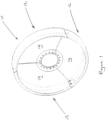
Fig. 1 is a perspective view of a segmented wheel according to a first embodiment of the invention; -
Fig . 2 is a partially exploded view offigure 1 ; -
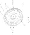
Fig . 3 is a perspective view of a segmented wheel according to a further embodiment of the invention; -
Fig . 4 is an exploded view of the wheel offigure 3 ; -
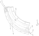
Fig . 5 is a close up view of the wheel offigure 3 ; -
Fig . 6 is a further close up view of the wheel offigure 3 ; -
Fig . 7 is an end on view of a segment of the wheel offigure 3 ; -
Fig . 8 is a side on view of the segment offigure 7 ; -
Fig . 9 is a perspective view of the segment offigure 7 ; -
Fig . 10 is a further perspective view of the segment offigure 7 . - The drawings are provided by way of reference only, and will be acknowledged as not to scale.
- With reference to
Figure 1 andfigure 2 , there is shown awheel 10 for an endless track system. In this embodiment thewheel 10 has threesegments 12. - In an embodiment, the
wheel 10 comprises threesegments 12. Each of thesegments 12 is substantially identical. - Each
segment 12 comprises a support portion 14 and arim portion 18. - The support portion 14 is an annular sector in shape having a central connection portion 20, a
body portion 22, anouter portion 24 and acircumferential flange 16. - The central connection portion 20 is configured for connection to an axle flange or the like by any suitable means, for example bolts inserted through bolt holes 26 and attached to an axle flange or hub (not shown). Alternatively the connection portion 20 may be connected to a hub disc (not shown) which is in turn attached to an axle.
- The
body portion 22 extends radially outward from the central connection portion 20 becoming theouter portion 24. In this specific example thebody portion 22 is substantially flat, in other examples thebody portion 22 may include localised thickening of material for strengthening and/or apertures to reduce theoverall segment 12 weight. - The
circumferential flange 16 comprises an inner face 28, anouter face 30 and an interface portion 32 at each end of thecircumferential flange 16. Thecircumferential flange 16 extends seamlessly from theouter portion 24 substantially perpendicularly to the plane of thebody portion 22. - The
outer face 30 provides a surface for attachment of therim portion 18 and faces away from the axis of rotation of thewheel 10. - Each interface portion 32 abuts with the interface portion 32 of an
adjacent segment 12 when thesegments 12 are connected to form thewheel 10. The interface portion 32 in this specific example includes corresponding chamfered faces 34 and fastener holes 36 for bolts. - The interface portion 32 may include any suitable means for securing
adjacent segments 12 together for example welding, riveting or adhesive bonding. - The inner face 28 faces toward the axis of rotation of the
wheel 10. - The inner face 28 includes debris ejectors 38. The debris ejectors 38 are configured to urge debris collecting on the inner face 28, away from the plane of the
body portion 22 thereby helping to reduce debris accumulation on thewheel 10. In this example the debris ejectors 38 bridge the interface portion 32 of thecircumferential flange 16, however in other examples the debris ejectors 38 may be provided on the inner face 28 distanced from the interface portions 32 or may be omitted entirely. In this specific example the debris ejectors 38 provide for localised thickening and strengthening of thecircumferential flange 16 thereby strengthening the fastener holes 36 and therefore the arrangement of thesegments 12 when connected to form thewheel 10. - The support portion 14 and the
circumferential flange 16 in this specific example are a single metallic component, for example pressed mild steel, however they may be two separate components which are joined together or a single spun or moulded or pressed component, it will be understood that any suitable forming process may be used. - The
rim portion 18 is of an elastomeric material and is attached using any suitable means to theouter face 30 of thecircumferential flange 16. - In use, the
wheel 10 is mounted to a vehicle, for example an agricultural tractor, thewheel 10 either supporting and/or driving an endless belt system to propel the vehicle. Therim portion 18 contacts the inside face of an endless track (not shown). - Since the
wheel 10 is constructed of segments the moulds which may be used to apply therim portion 18 to the support portion 14 can be much smaller than the mould size that would be required to apply arim portion 18 to a wheel that was not constructed of sub segments. - By reducing the size of moulds and tooling required to apply the
rim portion 18 to the support portion 14, the overall cost of manufacture of thewheel 10 can be reduced. - With reference to
figures 3 to 10 a further embodiment of the invention is shown. A wheel 110 for an endless track system comprises five segments 112 and a hub portion 113, which is also known as a hub disc. - The hub portion 113 is generally disc shaped and comprises are number of fastener holes which are suitable for the attachment of the segments 112 to the disc. The hub portion 113 includes a
central flange 170 which is provided for the attachment of the hub portion 113 and thereby the wheel 110 to the axle (not shown) of a vehicle. - Each of the five segments 112 is substantially identical and each comprises a
support portion 114 and a rim portion 118. Although five segments 112 are shown in this embodiment it will be understood that less or more segments may be used depending on the application and preferred construction of the wheel 110. - The
support portions 114 comprise a central connection portion 120, a body portion 122, an outer portion 124 and a circumferential flange 116. - The central connection portion 120 is configured for connection to the hub portion 113 by any suitable means, for example bolts 125 inserted through bolt holes 126. Washers 127 may be held under the head of the bolts 125 in a conventional manner.
- The body portion 122 extends radially outward from the central connection portion 120 terminating at the outer portion 124 thereby forming an arcuate member. In this specific example the body portion 122 includes localised thickening 129 of material for strengthening in proximity to the bolt holes 126.
- The circumferential flange 116 comprises an inner face 128, an outer face 130 and an interface portion 132 at each end of the circumferential flange 116. The circumferential flange 116 is in this embodiment an extension of the outer portion 124 extending substantially perpendicularly to the plane of the body portion 122 and outer portion 124.
- The outer face 130 provides a surface for attachment of the rim portion 118 and is orientated to face away from the axis of rotation of the wheel 110.
- Each interface portion 132 in this specific example include corresponding, interlocking formations 150. The interlocking formations 150 are best seen individually in
figures 9 and10 and infigure 6 which shows the interlocking formations 150 in an engaged position. In the engaged position the tongue 152 of one segment 112 interlocks with thegroove 154 to secure adjacent segments 112 relative to each other. - The inner face 128 may include debris ejectors 138. The debris ejectors 138 are configured to propel debris that may collect on the inner face 128, out of the wheel 110 and away from a vehicle, thereby helping to reduce debris accumulation on the wheel 110. With reference to
figure 5 , the debris ejectors 138 are formed from two parts, one on either side of the interface portion 132 of the circumferential flange 116, however in other examples the debris ejectors 138 may be provided on the inner face 128 away from the interface portions 132 or may be omitted entirely. In this specific example the debris ejectors 138 are formed from localised thickening of the circumferential flange 116 and also act to strengthen the interface between adjacent segments 112. - The
support portion 114 and the circumferential flange 116 are in this embodiment a single component of pressed mild steel, however they may be two separate components which are joined together or a single spun or moulded or pressed component, it will be understood that any suitable forming process may be used to manufacture thesupport portions 114. - The rim portion 118 is affixed to the outer surface 130 by any suitable means, for example by over moulding or bonding. Generally the rim portion 118 is constructed of an elastomeric material.
- In this example, the rim portion 118 includes a
tread pattern 160 which may be for example moulded or cut into the rim portion 118. Thetread pattern 160 comprises a regular series oftroughs 162 and peaks 164. Thetread pattern 160 is arranged such that debris that may be caught between the rim portion 118 and a track when the wheel 110 is in use, is ejected so as to avoid damage to the wheel 110 and a track which rides upon the said wheel 110. Thetread pattern 160 is so arranged that when thesegments 114 are attached to one another to form a wheel 110, thetread pattern 160 continues uninterrupted over the interfaces ofadjacent segments 114, this is best seen infigure 6 at reference 166. Putting it another way, thetread pattern 160 can be profiled to be continuous once the segments 112 are assembled into a wheel 110. - The invention is not limited to the embodiments or examples described herein, and may be modified or adapted without departing from the scope of the present invention as defined in the appended claims.
Claims (10)
- A wheel (10; 110) for use with an endless track system, the wheel comprising at least three segments (12; 112), each of the segments being substantially identical, wherein each of the segments comprises a support portion (14; 114), a circumferential flange (16; 116) and a rim portion (18; 118) wherein the rim portion is affixed to an outer face (30; 130) of the circumferential flange; characterised in that the segments (12; 112) are configured to attach to each other thereby forming the wheel.
- A wheel (10; 110) according to claim 1 wherein the rim portion (18; 118) is an elastomer.
- A wheel (10; 110) according to claim 1 or claim 2 wherein the rim portion (18; 118) is bonded to the outer face (30; 130).
- A wheel (10; 110) according to any preceding claim wherein each segment (12; 112) further comprises an inner edge (20; 120), the inner edge configured for attachment to a hub portion (113) or an axle flange.
- A wheel (10; 110) according to claim 4 wherein the inner edge (20; 120) is configured to be bolted to a hub portion (113) or axle flange.
- A wheel (10) according to any preceding claim wherein each segment (12) is configured to be bolted to each adjacent segment.
- A wheel (110) according to any preceding claim wherein each segment (112) includes corresponding interlocking formations (150) configured to join each segment to an adjacent segment.
- A wheel (10); 110) according to any preceding claim wherein the circumferential flange (16; 116) further comprises an inner face (28; 128), and wherein the inner face is provided with a debris ejection formation (38; 138) at the interface of two segments.
- A wheel (110) according to any preceding claim wherein the rim portion (18; 118) further comprises an exterior face for contact with an endless track, wherein the exterior face comprises a plurality of grooves (162) the grooves for ejecting debris caught between the wheel and endless track.
- A wheel (110) according to claim 9 wherein the plurality of grooves (162) are arranged such that a groove at the interface of two segments (112) bridges the adjacent segments uninterrupted.
Applications Claiming Priority (2)
| Application Number | Priority Date | Filing Date | Title |
|---|---|---|---|
| US201862760676P | 2018-11-13 | 2018-11-13 | |
| PCT/IB2019/056973 WO2020099946A1 (en) | 2018-11-13 | 2019-08-19 | Segmented wheel |
Publications (2)
| Publication Number | Publication Date |
|---|---|
| EP3880544A1 EP3880544A1 (en) | 2021-09-22 |
| EP3880544B1 true EP3880544B1 (en) | 2023-10-18 |
Family
ID=68104693
Family Applications (1)
| Application Number | Title | Priority Date | Filing Date |
|---|---|---|---|
| EP19779982.8A Active EP3880544B1 (en) | 2018-11-13 | 2019-08-19 | Segmented wheel |
Country Status (3)
| Country | Link |
|---|---|
| US (1) | US12291291B2 (en) |
| EP (1) | EP3880544B1 (en) |
| WO (1) | WO2020099946A1 (en) |
Families Citing this family (1)
| Publication number | Priority date | Publication date | Assignee | Title |
|---|---|---|---|---|
| US11794830B2 (en) * | 2021-01-22 | 2023-10-24 | Caterpillar Inc. | Sprocket locking segments |
Family Cites Families (14)
| Publication number | Priority date | Publication date | Assignee | Title |
|---|---|---|---|---|
| US1391719A (en) * | 1920-07-29 | 1921-09-27 | William B Conyngham | Sectional gear-wheel |
| US4058023A (en) * | 1975-12-08 | 1977-11-15 | Esco Corporation | Rotating assembly for material handling equipment |
| US4449756A (en) * | 1982-03-09 | 1984-05-22 | Motor Wheel Corporation | Tracked vehicle road wheel |
| US4950030A (en) * | 1986-05-30 | 1990-08-21 | Motor Wheel Corporation | Wheel for a track laying vehicle |
| US6652043B2 (en) * | 2000-04-20 | 2003-11-25 | Caterpillar Inc | Reduced sound transmitting idler for track-type vehicles |
| US6733093B2 (en) * | 2002-07-25 | 2004-05-11 | Soucy International Inc. | Split wheel and method for installing endless track |
| US7198337B2 (en) * | 2003-01-23 | 2007-04-03 | Kinze Manufacturing, Inc. | Wheel for belted track vehicles |
| EP1721758A1 (en) * | 2005-05-13 | 2006-11-15 | JohnsonDiversey, Inc. | Non-slipping wheel |
| GB2435867B (en) | 2006-03-06 | 2008-02-06 | Stephen John Heard | A method of fitting a track to a track apparatus |
| US8672064B2 (en) * | 2007-09-07 | 2014-03-18 | Loegering Mfg. Inc. | Apparatus for converting a wheeled vehicle to a tracked vehicle |
| USD644670S1 (en) * | 2010-06-21 | 2011-09-06 | Claas Kgaa Mbh | Vehicle crawler mechanism |
| CA2744630C (en) | 2010-06-30 | 2018-10-09 | Camoplast Solideal Inc. | Wheel of a track assembly of a tracked vehicle |
| US8678054B2 (en) * | 2011-03-01 | 2014-03-25 | Scennco, Inc. | Segmented tire apparatus |
| US20120241531A1 (en) * | 2011-03-22 | 2012-09-27 | Michael Werner | Non-Pneumatic Irrigation System Tower Support Wheel |
-
2019
- 2019-08-19 EP EP19779982.8A patent/EP3880544B1/en active Active
- 2019-08-19 US US17/293,016 patent/US12291291B2/en active Active
- 2019-08-19 WO PCT/IB2019/056973 patent/WO2020099946A1/en not_active Ceased
Also Published As
| Publication number | Publication date |
|---|---|
| US12291291B2 (en) | 2025-05-06 |
| EP3880544A1 (en) | 2021-09-22 |
| WO2020099946A1 (en) | 2020-05-22 |
| US20210394838A1 (en) | 2021-12-23 |
Similar Documents
| Publication | Publication Date | Title |
|---|---|---|
| EP2736794B1 (en) | Track-module apparatus and open drive wheel therefor | |
| US9663918B2 (en) | Drive wheel for a track assembly of a work vehicle | |
| US5899541A (en) | Low profile rubber tracked snow vehicle with snow-clearing drive wheels | |
| EP3116770B1 (en) | Vehicle track assembly having tapered wheels | |
| CA2832740C (en) | Segmented track and track segment therefor | |
| WO2004113154A1 (en) | Drive wheel for track apparatus | |
| US7370918B2 (en) | Wheel assembly for a tracked vehicle and anti-accumulation sleeve therefor | |
| US20040145239A1 (en) | Wheel for belted track vehicles | |
| US12291291B2 (en) | Segmented wheel | |
| US7159955B2 (en) | Traction band and sprocket for vehicles | |
| US10654533B2 (en) | Wheel debris ejector for tracked vehicle | |
| US11560189B2 (en) | Track elements for forming a continuous over tyre track with strength enhancement structure | |
| US20070247002A1 (en) | Wheel with mechanically bonded rim for tracked vehicles | |
| CA2508741C (en) | Wheel assembly for a tracked vehicle and anti-accumulation sleeve therefor | |
| KR101984854B1 (en) | Segment wheel and cart having it | |
| US9834265B2 (en) | Rubber track system | |
| EP1623847A1 (en) | Pneumatic driver tire for tracked vehicle | |
| JP2002316504A (en) | Wheel body, and wheel for agricultural use | |
| AU2023312390A1 (en) | Track assembly, vehicle having same, wheel, and endless track for use with same | |
| US20040232767A1 (en) | Supporting disk | |
| NZ620678B2 (en) | Track-module apparatus and open drive wheel therefor | |
| HK1196341A (en) | Track-module apparatus and open drive wheel therefor | |
| HK1235037A1 (en) | Vehicle track assembly having tapered wheels | |
| HK1196341B (en) | Track-module apparatus and open drive wheel therefor |
Legal Events
| Date | Code | Title | Description |
|---|---|---|---|
| STAA | Information on the status of an ep patent application or granted ep patent |
Free format text: STATUS: UNKNOWN |
|
| STAA | Information on the status of an ep patent application or granted ep patent |
Free format text: STATUS: THE INTERNATIONAL PUBLICATION HAS BEEN MADE |
|
| PUAI | Public reference made under article 153(3) epc to a published international application that has entered the european phase |
Free format text: ORIGINAL CODE: 0009012 |
|
| STAA | Information on the status of an ep patent application or granted ep patent |
Free format text: STATUS: REQUEST FOR EXAMINATION WAS MADE |
|
| 17P | Request for examination filed |
Effective date: 20210614 |
|
| AK | Designated contracting states |
Kind code of ref document: A1 Designated state(s): AL AT BE BG CH CY CZ DE DK EE ES FI FR GB GR HR HU IE IS IT LI LT LU LV MC MK MT NL NO PL PT RO RS SE SI SK SM TR |
|
| DAV | Request for validation of the european patent (deleted) | ||
| DAX | Request for extension of the european patent (deleted) | ||
| P01 | Opt-out of the competence of the unified patent court (upc) registered |
Effective date: 20230518 |
|
| GRAP | Despatch of communication of intention to grant a patent |
Free format text: ORIGINAL CODE: EPIDOSNIGR1 |
|
| STAA | Information on the status of an ep patent application or granted ep patent |
Free format text: STATUS: GRANT OF PATENT IS INTENDED |
|
| INTG | Intention to grant announced |
Effective date: 20230720 |
|
| GRAS | Grant fee paid |
Free format text: ORIGINAL CODE: EPIDOSNIGR3 |
|
| GRAA | (expected) grant |
Free format text: ORIGINAL CODE: 0009210 |
|
| STAA | Information on the status of an ep patent application or granted ep patent |
Free format text: STATUS: THE PATENT HAS BEEN GRANTED |
|
| AK | Designated contracting states |
Kind code of ref document: B1 Designated state(s): AL AT BE BG CH CY CZ DE DK EE ES FI FR GB GR HR HU IE IS IT LI LT LU LV MC MK MT NL NO PL PT RO RS SE SI SK SM TR |
|
| REG | Reference to a national code |
Ref country code: GB Ref legal event code: FG4D |
|
| REG | Reference to a national code |
Ref country code: CH Ref legal event code: EP |
|
| REG | Reference to a national code |
Ref country code: IE Ref legal event code: FG4D |
|
| REG | Reference to a national code |
Ref country code: DE Ref legal event code: R096 Ref document number: 602019039667 Country of ref document: DE |
|
| REG | Reference to a national code |
Ref country code: LT Ref legal event code: MG9D |
|
| REG | Reference to a national code |
Ref country code: NL Ref legal event code: MP Effective date: 20231018 |
|
| REG | Reference to a national code |
Ref country code: AT Ref legal event code: MK05 Ref document number: 1622215 Country of ref document: AT Kind code of ref document: T Effective date: 20231018 |
|
| PG25 | Lapsed in a contracting state [announced via postgrant information from national office to epo] |
Ref country code: NL Free format text: LAPSE BECAUSE OF FAILURE TO SUBMIT A TRANSLATION OF THE DESCRIPTION OR TO PAY THE FEE WITHIN THE PRESCRIBED TIME-LIMIT Effective date: 20231018 |
|
| PG25 | Lapsed in a contracting state [announced via postgrant information from national office to epo] |
Ref country code: GR Free format text: LAPSE BECAUSE OF FAILURE TO SUBMIT A TRANSLATION OF THE DESCRIPTION OR TO PAY THE FEE WITHIN THE PRESCRIBED TIME-LIMIT Effective date: 20240119 |
|
| PG25 | Lapsed in a contracting state [announced via postgrant information from national office to epo] |
Ref country code: IS Free format text: LAPSE BECAUSE OF FAILURE TO SUBMIT A TRANSLATION OF THE DESCRIPTION OR TO PAY THE FEE WITHIN THE PRESCRIBED TIME-LIMIT Effective date: 20240218 |
|
| PG25 | Lapsed in a contracting state [announced via postgrant information from national office to epo] |
Ref country code: LT Free format text: LAPSE BECAUSE OF FAILURE TO SUBMIT A TRANSLATION OF THE DESCRIPTION OR TO PAY THE FEE WITHIN THE PRESCRIBED TIME-LIMIT Effective date: 20231018 |
|
| PG25 | Lapsed in a contracting state [announced via postgrant information from national office to epo] |
Ref country code: AT Free format text: LAPSE BECAUSE OF FAILURE TO SUBMIT A TRANSLATION OF THE DESCRIPTION OR TO PAY THE FEE WITHIN THE PRESCRIBED TIME-LIMIT Effective date: 20231018 |
|
| PG25 | Lapsed in a contracting state [announced via postgrant information from national office to epo] |
Ref country code: ES Free format text: LAPSE BECAUSE OF FAILURE TO SUBMIT A TRANSLATION OF THE DESCRIPTION OR TO PAY THE FEE WITHIN THE PRESCRIBED TIME-LIMIT Effective date: 20231018 |
|
| PG25 | Lapsed in a contracting state [announced via postgrant information from national office to epo] |
Ref country code: LT Free format text: LAPSE BECAUSE OF FAILURE TO SUBMIT A TRANSLATION OF THE DESCRIPTION OR TO PAY THE FEE WITHIN THE PRESCRIBED TIME-LIMIT Effective date: 20231018 Ref country code: IS Free format text: LAPSE BECAUSE OF FAILURE TO SUBMIT A TRANSLATION OF THE DESCRIPTION OR TO PAY THE FEE WITHIN THE PRESCRIBED TIME-LIMIT Effective date: 20240218 Ref country code: GR Free format text: LAPSE BECAUSE OF FAILURE TO SUBMIT A TRANSLATION OF THE DESCRIPTION OR TO PAY THE FEE WITHIN THE PRESCRIBED TIME-LIMIT Effective date: 20240119 Ref country code: ES Free format text: LAPSE BECAUSE OF FAILURE TO SUBMIT A TRANSLATION OF THE DESCRIPTION OR TO PAY THE FEE WITHIN THE PRESCRIBED TIME-LIMIT Effective date: 20231018 Ref country code: BG Free format text: LAPSE BECAUSE OF FAILURE TO SUBMIT A TRANSLATION OF THE DESCRIPTION OR TO PAY THE FEE WITHIN THE PRESCRIBED TIME-LIMIT Effective date: 20240118 Ref country code: AT Free format text: LAPSE BECAUSE OF FAILURE TO SUBMIT A TRANSLATION OF THE DESCRIPTION OR TO PAY THE FEE WITHIN THE PRESCRIBED TIME-LIMIT Effective date: 20231018 Ref country code: PT Free format text: LAPSE BECAUSE OF FAILURE TO SUBMIT A TRANSLATION OF THE DESCRIPTION OR TO PAY THE FEE WITHIN THE PRESCRIBED TIME-LIMIT Effective date: 20240219 |
|
| PG25 | Lapsed in a contracting state [announced via postgrant information from national office to epo] |
Ref country code: SE Free format text: LAPSE BECAUSE OF FAILURE TO SUBMIT A TRANSLATION OF THE DESCRIPTION OR TO PAY THE FEE WITHIN THE PRESCRIBED TIME-LIMIT Effective date: 20231018 Ref country code: RS Free format text: LAPSE BECAUSE OF FAILURE TO SUBMIT A TRANSLATION OF THE DESCRIPTION OR TO PAY THE FEE WITHIN THE PRESCRIBED TIME-LIMIT Effective date: 20231018 Ref country code: PL Free format text: LAPSE BECAUSE OF FAILURE TO SUBMIT A TRANSLATION OF THE DESCRIPTION OR TO PAY THE FEE WITHIN THE PRESCRIBED TIME-LIMIT Effective date: 20231018 Ref country code: NO Free format text: LAPSE BECAUSE OF FAILURE TO SUBMIT A TRANSLATION OF THE DESCRIPTION OR TO PAY THE FEE WITHIN THE PRESCRIBED TIME-LIMIT Effective date: 20240118 Ref country code: LV Free format text: LAPSE BECAUSE OF FAILURE TO SUBMIT A TRANSLATION OF THE DESCRIPTION OR TO PAY THE FEE WITHIN THE PRESCRIBED TIME-LIMIT Effective date: 20231018 Ref country code: HR Free format text: LAPSE BECAUSE OF FAILURE TO SUBMIT A TRANSLATION OF THE DESCRIPTION OR TO PAY THE FEE WITHIN THE PRESCRIBED TIME-LIMIT Effective date: 20231018 |
|
| PG25 | Lapsed in a contracting state [announced via postgrant information from national office to epo] |
Ref country code: DK Free format text: LAPSE BECAUSE OF FAILURE TO SUBMIT A TRANSLATION OF THE DESCRIPTION OR TO PAY THE FEE WITHIN THE PRESCRIBED TIME-LIMIT Effective date: 20231018 |
|
| REG | Reference to a national code |
Ref country code: DE Ref legal event code: R097 Ref document number: 602019039667 Country of ref document: DE |
|
| PG25 | Lapsed in a contracting state [announced via postgrant information from national office to epo] |
Ref country code: CZ Free format text: LAPSE BECAUSE OF FAILURE TO SUBMIT A TRANSLATION OF THE DESCRIPTION OR TO PAY THE FEE WITHIN THE PRESCRIBED TIME-LIMIT Effective date: 20231018 |
|
| PG25 | Lapsed in a contracting state [announced via postgrant information from national office to epo] |
Ref country code: SK Free format text: LAPSE BECAUSE OF FAILURE TO SUBMIT A TRANSLATION OF THE DESCRIPTION OR TO PAY THE FEE WITHIN THE PRESCRIBED TIME-LIMIT Effective date: 20231018 |
|
| PG25 | Lapsed in a contracting state [announced via postgrant information from national office to epo] |
Ref country code: SM Free format text: LAPSE BECAUSE OF FAILURE TO SUBMIT A TRANSLATION OF THE DESCRIPTION OR TO PAY THE FEE WITHIN THE PRESCRIBED TIME-LIMIT Effective date: 20231018 Ref country code: SK Free format text: LAPSE BECAUSE OF FAILURE TO SUBMIT A TRANSLATION OF THE DESCRIPTION OR TO PAY THE FEE WITHIN THE PRESCRIBED TIME-LIMIT Effective date: 20231018 Ref country code: RO Free format text: LAPSE BECAUSE OF FAILURE TO SUBMIT A TRANSLATION OF THE DESCRIPTION OR TO PAY THE FEE WITHIN THE PRESCRIBED TIME-LIMIT Effective date: 20231018 Ref country code: IT Free format text: LAPSE BECAUSE OF FAILURE TO SUBMIT A TRANSLATION OF THE DESCRIPTION OR TO PAY THE FEE WITHIN THE PRESCRIBED TIME-LIMIT Effective date: 20231018 Ref country code: EE Free format text: LAPSE BECAUSE OF FAILURE TO SUBMIT A TRANSLATION OF THE DESCRIPTION OR TO PAY THE FEE WITHIN THE PRESCRIBED TIME-LIMIT Effective date: 20231018 Ref country code: DK Free format text: LAPSE BECAUSE OF FAILURE TO SUBMIT A TRANSLATION OF THE DESCRIPTION OR TO PAY THE FEE WITHIN THE PRESCRIBED TIME-LIMIT Effective date: 20231018 Ref country code: CZ Free format text: LAPSE BECAUSE OF FAILURE TO SUBMIT A TRANSLATION OF THE DESCRIPTION OR TO PAY THE FEE WITHIN THE PRESCRIBED TIME-LIMIT Effective date: 20231018 |
|
| PLBE | No opposition filed within time limit |
Free format text: ORIGINAL CODE: 0009261 |
|
| STAA | Information on the status of an ep patent application or granted ep patent |
Free format text: STATUS: NO OPPOSITION FILED WITHIN TIME LIMIT |
|
| 26N | No opposition filed |
Effective date: 20240719 |
|
| PG25 | Lapsed in a contracting state [announced via postgrant information from national office to epo] |
Ref country code: SI Free format text: LAPSE BECAUSE OF FAILURE TO SUBMIT A TRANSLATION OF THE DESCRIPTION OR TO PAY THE FEE WITHIN THE PRESCRIBED TIME-LIMIT Effective date: 20231018 |
|
| PG25 | Lapsed in a contracting state [announced via postgrant information from national office to epo] |
Ref country code: SI Free format text: LAPSE BECAUSE OF FAILURE TO SUBMIT A TRANSLATION OF THE DESCRIPTION OR TO PAY THE FEE WITHIN THE PRESCRIBED TIME-LIMIT Effective date: 20231018 |
|
| REG | Reference to a national code |
Ref country code: CH Ref legal event code: PL |
|
| PG25 | Lapsed in a contracting state [announced via postgrant information from national office to epo] |
Ref country code: LU Free format text: LAPSE BECAUSE OF NON-PAYMENT OF DUE FEES Effective date: 20240819 |
|
| PG25 | Lapsed in a contracting state [announced via postgrant information from national office to epo] |
Ref country code: MC Free format text: LAPSE BECAUSE OF FAILURE TO SUBMIT A TRANSLATION OF THE DESCRIPTION OR TO PAY THE FEE WITHIN THE PRESCRIBED TIME-LIMIT Effective date: 20231018 Ref country code: CH Free format text: LAPSE BECAUSE OF NON-PAYMENT OF DUE FEES Effective date: 20240831 |
|
| REG | Reference to a national code |
Ref country code: BE Ref legal event code: MM Effective date: 20240831 |
|
| PG25 | Lapsed in a contracting state [announced via postgrant information from national office to epo] |
Ref country code: BE Free format text: LAPSE BECAUSE OF NON-PAYMENT OF DUE FEES Effective date: 20240831 |
|
| PG25 | Lapsed in a contracting state [announced via postgrant information from national office to epo] |
Ref country code: IE Free format text: LAPSE BECAUSE OF NON-PAYMENT OF DUE FEES Effective date: 20240819 |
|
| PG25 | Lapsed in a contracting state [announced via postgrant information from national office to epo] |
Ref country code: FI Free format text: LAPSE BECAUSE OF FAILURE TO SUBMIT A TRANSLATION OF THE DESCRIPTION OR TO PAY THE FEE WITHIN THE PRESCRIBED TIME-LIMIT Effective date: 20231019 |
|
| PGFP | Annual fee paid to national office [announced via postgrant information from national office to epo] |
Ref country code: DE Payment date: 20250820 Year of fee payment: 7 |
|
| PGFP | Annual fee paid to national office [announced via postgrant information from national office to epo] |
Ref country code: GB Payment date: 20250820 Year of fee payment: 7 |
|
| PGFP | Annual fee paid to national office [announced via postgrant information from national office to epo] |
Ref country code: FR Payment date: 20250828 Year of fee payment: 7 |
|
| PG25 | Lapsed in a contracting state [announced via postgrant information from national office to epo] |
Ref country code: CY Free format text: LAPSE BECAUSE OF FAILURE TO SUBMIT A TRANSLATION OF THE DESCRIPTION OR TO PAY THE FEE WITHIN THE PRESCRIBED TIME-LIMIT; INVALID AB INITIO Effective date: 20190819 |
|
| PG25 | Lapsed in a contracting state [announced via postgrant information from national office to epo] |
Ref country code: HU Free format text: LAPSE BECAUSE OF FAILURE TO SUBMIT A TRANSLATION OF THE DESCRIPTION OR TO PAY THE FEE WITHIN THE PRESCRIBED TIME-LIMIT; INVALID AB INITIO Effective date: 20190819 |