EP3880094B1 - Laparoscopic grasper with force-limiting grasping mechanism - Google Patents
Laparoscopic grasper with force-limiting grasping mechanism Download PDFInfo
- Publication number
- EP3880094B1 EP3880094B1 EP19818308.9A EP19818308A EP3880094B1 EP 3880094 B1 EP3880094 B1 EP 3880094B1 EP 19818308 A EP19818308 A EP 19818308A EP 3880094 B1 EP3880094 B1 EP 3880094B1
- Authority
- EP
- European Patent Office
- Prior art keywords
- actuator
- jaw
- assembly
- grasping instrument
- jaw assembly
- Prior art date
- Legal status (The legal status is an assumption and is not a legal conclusion. Google has not performed a legal analysis and makes no representation as to the accuracy of the status listed.)
- Active
Links
Images





Classifications
-
- A—HUMAN NECESSITIES
- A61—MEDICAL OR VETERINARY SCIENCE; HYGIENE
- A61B—DIAGNOSIS; SURGERY; IDENTIFICATION
- A61B17/00—Surgical instruments, devices or methods
- A61B17/28—Surgical forceps
- A61B17/29—Forceps for use in minimally invasive surgery
-
- A—HUMAN NECESSITIES
- A61—MEDICAL OR VETERINARY SCIENCE; HYGIENE
- A61B—DIAGNOSIS; SURGERY; IDENTIFICATION
- A61B17/00—Surgical instruments, devices or methods
- A61B17/28—Surgical forceps
- A61B17/29—Forceps for use in minimally invasive surgery
- A61B17/2909—Handles
-
- A—HUMAN NECESSITIES
- A61—MEDICAL OR VETERINARY SCIENCE; HYGIENE
- A61B—DIAGNOSIS; SURGERY; IDENTIFICATION
- A61B90/00—Instruments, implements or accessories specially adapted for surgery or diagnosis and not covered by any of the groups A61B1/00 - A61B50/00, e.g. for luxation treatment or for protecting wound edges
- A61B90/03—Automatic limiting or abutting means, e.g. for safety
-
- A—HUMAN NECESSITIES
- A61—MEDICAL OR VETERINARY SCIENCE; HYGIENE
- A61B—DIAGNOSIS; SURGERY; IDENTIFICATION
- A61B17/00—Surgical instruments, devices or methods
- A61B2017/00367—Details of actuation of instruments, e.g. relations between pushing buttons, or the like, and activation of the tool, working tip, or the like
- A61B2017/00389—Button or wheel for performing multiple functions, e.g. rotation of shaft and end effector
-
- A—HUMAN NECESSITIES
- A61—MEDICAL OR VETERINARY SCIENCE; HYGIENE
- A61B—DIAGNOSIS; SURGERY; IDENTIFICATION
- A61B17/00—Surgical instruments, devices or methods
- A61B2017/0042—Surgical instruments, devices or methods with special provisions for gripping
- A61B2017/00424—Surgical instruments, devices or methods with special provisions for gripping ergonomic, e.g. fitting in fist
-
- A—HUMAN NECESSITIES
- A61—MEDICAL OR VETERINARY SCIENCE; HYGIENE
- A61B—DIAGNOSIS; SURGERY; IDENTIFICATION
- A61B17/00—Surgical instruments, devices or methods
- A61B2017/00831—Material properties
- A61B2017/00858—Material properties high friction or non-slip
-
- A—HUMAN NECESSITIES
- A61—MEDICAL OR VETERINARY SCIENCE; HYGIENE
- A61B—DIAGNOSIS; SURGERY; IDENTIFICATION
- A61B17/00—Surgical instruments, devices or methods
- A61B2017/00831—Material properties
- A61B2017/00862—Material properties elastic or resilient
-
- A—HUMAN NECESSITIES
- A61—MEDICAL OR VETERINARY SCIENCE; HYGIENE
- A61B—DIAGNOSIS; SURGERY; IDENTIFICATION
- A61B17/00—Surgical instruments, devices or methods
- A61B17/28—Surgical forceps
- A61B17/2812—Surgical forceps with a single pivotal connection
- A61B17/282—Jaws
- A61B2017/2825—Inserts of different material in jaws
-
- A—HUMAN NECESSITIES
- A61—MEDICAL OR VETERINARY SCIENCE; HYGIENE
- A61B—DIAGNOSIS; SURGERY; IDENTIFICATION
- A61B17/00—Surgical instruments, devices or methods
- A61B17/28—Surgical forceps
- A61B17/29—Forceps for use in minimally invasive surgery
- A61B2017/2901—Details of shaft
-
- A—HUMAN NECESSITIES
- A61—MEDICAL OR VETERINARY SCIENCE; HYGIENE
- A61B—DIAGNOSIS; SURGERY; IDENTIFICATION
- A61B17/00—Surgical instruments, devices or methods
- A61B17/28—Surgical forceps
- A61B17/29—Forceps for use in minimally invasive surgery
- A61B2017/2901—Details of shaft
- A61B2017/2902—Details of shaft characterized by features of the actuating rod
-
- A—HUMAN NECESSITIES
- A61—MEDICAL OR VETERINARY SCIENCE; HYGIENE
- A61B—DIAGNOSIS; SURGERY; IDENTIFICATION
- A61B17/00—Surgical instruments, devices or methods
- A61B17/28—Surgical forceps
- A61B17/29—Forceps for use in minimally invasive surgery
- A61B2017/2901—Details of shaft
- A61B2017/2904—Details of shaft curved, but rigid
-
- A—HUMAN NECESSITIES
- A61—MEDICAL OR VETERINARY SCIENCE; HYGIENE
- A61B—DIAGNOSIS; SURGERY; IDENTIFICATION
- A61B17/00—Surgical instruments, devices or methods
- A61B17/28—Surgical forceps
- A61B17/29—Forceps for use in minimally invasive surgery
- A61B2017/2901—Details of shaft
- A61B2017/2905—Details of shaft flexible
-
- A—HUMAN NECESSITIES
- A61—MEDICAL OR VETERINARY SCIENCE; HYGIENE
- A61B—DIAGNOSIS; SURGERY; IDENTIFICATION
- A61B17/00—Surgical instruments, devices or methods
- A61B17/28—Surgical forceps
- A61B17/29—Forceps for use in minimally invasive surgery
- A61B17/2909—Handles
- A61B2017/2911—Handles rings
-
- A—HUMAN NECESSITIES
- A61—MEDICAL OR VETERINARY SCIENCE; HYGIENE
- A61B—DIAGNOSIS; SURGERY; IDENTIFICATION
- A61B17/00—Surgical instruments, devices or methods
- A61B17/28—Surgical forceps
- A61B17/29—Forceps for use in minimally invasive surgery
- A61B17/2909—Handles
- A61B2017/2912—Handles transmission of forces to actuating rod or piston
-
- A—HUMAN NECESSITIES
- A61—MEDICAL OR VETERINARY SCIENCE; HYGIENE
- A61B—DIAGNOSIS; SURGERY; IDENTIFICATION
- A61B17/00—Surgical instruments, devices or methods
- A61B17/28—Surgical forceps
- A61B17/29—Forceps for use in minimally invasive surgery
- A61B17/2909—Handles
- A61B2017/2912—Handles transmission of forces to actuating rod or piston
- A61B2017/2913—Handles transmission of forces to actuating rod or piston cams or guiding means
-
- A—HUMAN NECESSITIES
- A61—MEDICAL OR VETERINARY SCIENCE; HYGIENE
- A61B—DIAGNOSIS; SURGERY; IDENTIFICATION
- A61B17/00—Surgical instruments, devices or methods
- A61B17/28—Surgical forceps
- A61B17/29—Forceps for use in minimally invasive surgery
- A61B2017/2946—Locking means
-
- A—HUMAN NECESSITIES
- A61—MEDICAL OR VETERINARY SCIENCE; HYGIENE
- A61B—DIAGNOSIS; SURGERY; IDENTIFICATION
- A61B17/00—Surgical instruments, devices or methods
- A61B17/28—Surgical forceps
- A61B17/29—Forceps for use in minimally invasive surgery
- A61B2017/2947—Pivots
-
- A—HUMAN NECESSITIES
- A61—MEDICAL OR VETERINARY SCIENCE; HYGIENE
- A61B—DIAGNOSIS; SURGERY; IDENTIFICATION
- A61B17/00—Surgical instruments, devices or methods
- A61B17/28—Surgical forceps
- A61B17/29—Forceps for use in minimally invasive surgery
- A61B2017/2948—Sealing means, e.g. for sealing the interior from fluid entry
-
- A—HUMAN NECESSITIES
- A61—MEDICAL OR VETERINARY SCIENCE; HYGIENE
- A61B—DIAGNOSIS; SURGERY; IDENTIFICATION
- A61B90/00—Instruments, implements or accessories specially adapted for surgery or diagnosis and not covered by any of the groups A61B1/00 - A61B50/00, e.g. for luxation treatment or for protecting wound edges
- A61B90/03—Automatic limiting or abutting means, e.g. for safety
- A61B2090/033—Abutting means, stops, e.g. abutting on tissue or skin
- A61B2090/034—Abutting means, stops, e.g. abutting on tissue or skin abutting on parts of the device itself
- A61B2090/035—Abutting means, stops, e.g. abutting on tissue or skin abutting on parts of the device itself preventing further rotation
Definitions
- the present application relates to surgical devices and more particularly to laparoscopic grasping instruments used in minimally-invasive surgery.
- Conventional surgical grasping instruments have included grasping jaws comprised of a metallic material to grasp and manipulate tissue. Certain conventional surgical grasping instruments have also included force limiting mechanisms including relatively complex compression coil spring assemblies that require relatively large shaft diameters to accommodate. Other conventional grasping instruments have included no dedicated force limiting mechanism. Instead, these convention grasping instruments rely on flexibility and compliance of actuating handles to reduce the impact of forceful grasping.
- a surgical grasping instrument that can reduce the potential for trauma to grasped tissue. It is likewise desirable to provide a surgical grasping instrument that has a simplified mechanism that facilitates relatively low-cost manufacture and assembly. Furthermore, it is desirable to provide a surgical grasping instrument including atraumatic, force limiting features in a device configured for use with a small surgical access port diameter such as a port configured for use with 5mm instruments.
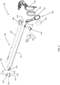
- the surgical grasping instrument 100 can extend between a proximal end and a distal end and can comprise an end effector such as a jaw assembly 200 at the distal end, a shaft assembly 300 extending between the proximal end and the distal end, and a handle assembly 400 at the proximal end.
- the surgical grasping instrument 100 can be configured for use in minimally-invasive surgical procedures such that it is sized and configured to be extended through a trocar cannula or other surgical access port.
- the shaft assembly 300 can comprise a generally tubular body having a smooth outer surface and an outer diameter sized for passage through a trocar cannula having a size classification to receive certain instruments such as, for example, a 12mm trocar, a 10mm trocar, and a 5mm trocar.
- certain aspects of the surgical instruments described herein can be adapted for use with surgical access ports having different sizes or in open surgical procedures.
- the jaw assembly 200 of the surgical grasping instrument 100 comprises a first jaw 210 coupled to a second jaw 230 at a pivot 250.
- the jaw assembly 200 can be actuated between an open configuration in which the first jaw 210 is spaced from the second jaw 230 and a closed configuration in which the first jaw 210 is approximated with the second jaw 230 to grasp an object such as tissue, vasculature, or another surgical instrument therebetween.
- the jaw assembly 200 can be configured to reduce the potential for tissue trauma during use.
- the first and/or second jaws 210, 230 can include an atraumatic pad formed thereon.
- the first jaw 210 comprises a first atraumatic jaw pad 220 and the second jaw 230 comprises a second atraumatic jaw pad 240.
- the first and second atraumatic pads 220, 240 can comprise soft, relatively low durometer atraumatic pads sold under the trademark LATIS ® .
- the jaw assembly 200 can include pad-less first and second jaws 210, 230 and pressure reduction at the jaws can be enhanced by a force reducing or limiting actuation mechanism.
- FIG. 1 an exploded view of the surgical grasping instrument 100 of Figure 1 is illustrated.
- the first and second jaws 210, 230 are pivotally coupled to one another and to shaft (not illustrated) at the pivot 250.
- An actuation post or pin 254 protrudes from each of the first and second jaws 210, 230 proximal of engagement with the pivot 250.
- the jaw assembly 200 is coupled to the distal end of the actuator 310 by a head member 360, which is positioned between proximal ends of each of the first and second jaws 210, 230.
- Each side of the head member 360 has a track 364 formed therein.
- each of the first and second jaws 210, 230 are positioned within respective tracks 364 such that proximal and distal movements of the actuator 310 and head member 360 with respect to the outer tube of the shaft moves the actuation pins 254 to open and close the first and second jaws 210, 230.
- a shim 370 can be positioned at the distal end of the head member 360 to maintain a desired spacing of the jaw assembly 200 and head member 360 within the outer tube.
- the shim 370 can have a saddle configuration positioned astride the head member 360 and proximal ends of the first and second jaws 210, 230 to reduce any tendency of the actuation post or pin 254 to become disengaged from the track 364 under load.
- the elongate shaft assembly 300 comprises an actuator 310, an outer tube 330 and a dielectric sleeve 340.
- the actuator can be slidably positioned within the outer tube 330.
- the dielectric sleeve 340 can be disposed around an outer surface of the outer tube 330 and provide electrical insulation for the elongate shaft assembly 300.
- the actuator 310 comprises a substantially planar member extending generally longitudinally between a proximal end 312 and a distal end 314.
- the substantially planar geometry of the actuator 310 is defined by a length between the proximal end 312 and the distal end 314, a height orthogonal to the length, and a width orthogonal to both the length and the height.
- the actuator 310 comprises a stack of a plurality of actuator strips, such as, for example, two actuator strips to provide an actuator 310 having desired stiffness, extension, and fatigue life characteristics.
- the handle assembly 400 comprises a housing formed of a pair of housing halves that define a stationary handle 410, a movable handle 420 pivotably coupled to the stationary handle 410 at a pivot pin of a locking mechanism 430, and a rotation knob 460.
- the stationary handle 410 can be contoured to be grasped in the fingers of a user's hand and the movable handle 420 can include a thumb ring to be engaged by a user's thumb and moved by flexion and extension of the user's thumb. It is contemplated that other configurations of handle assembly can be used with the elongate shaft assemblies and end effector assemblies described herein.
- the jaw assembly 200 of the surgical grasping instrument is illustrated in open ( Figure 3 and Figure 3A ), partially closed ( Figure 4 and Figure 4A ), and closed configurations ( Figure 5 and Figure 5A ).
- the first jaw 210 is spaced from the second jaw 230 such that a user can position the surgical grasping instrument in a surgical site with an object to be grasped positioned between the first and second jaws 210, 230.
- the first jaw 210 and the second jaw 230 are pivotably coupled to one another at a pivot 250 such as a linkage rivet, pin, or other pivotable assembly.
- the pivot 250 is also coupled to the outer tube 330 of the elongate shaft assembly 300 at the distal end of the elongate shaft assembly 300.
- the elongate shaft assembly 300 can further comprise a head member 360 that engages the first and second jaws 210, 230 of the jaw assembly 200 at engagement locations proximal the pivot 250.
- first and second jaws 210, 230 can each comprise an actuation pin protruding radially inwardly with respect to the elongate shaft assembly 300 at a location proximal the pivot 250, and the head member 360 can include a first groove, slot, or track 364 positioned to receive the actuation pin of the first jaw 210 and a second groove, slot, or track formed therein positioned to receive the actuation pin of the second jaw 230.
- the first track and the second track can extend transversely relative to the central longitudinal axis of the elongate shaft assembly 300 such that proximal and distal movement of the head member 360 pivots the first and second jaws 210, 230 relative to one another about the pivot 250.
- the elongate shaft assembly 300 can further include a jaw support member such as at least one shim member positioned within the outer tube 330 at the distal end to longitudinally align and maintain spacing of the head member 360 and the jaw assembly 200 relative to the central longitudinal axis.
- the elongate shaft assembly 300 can include a seal element 350 disposed between the head member 360 and an inner surface of the outer tube 330 to prevent fluid and gas ingress or leakage from a surgical site into the elongate shaft assembly.
- the elongate shaft assembly 300 can comprise an O-ring disposed retained by a groove in the head member 360.
- a proximal end of the head member 360 can be coupled to a distal end of the actuator 310.
- the proximal end of the head member 360 and the distal end of the actuator 310 can be configured to provide a coupling that is rotatable about the central longitudinal axis of the elongate shaft assembly 300.
- the proximal end of the head member 360 comprises a protruding annular post 362
- the distal end 314 of the actuator 310 can comprise a cutout sized and configured to receive the annular post 362 and allow rotation of the jaw assembly 200 relative to the central longitudinal axis of the elongate shaft assembly 300.
- rotation of the rotation knob 460 of the handle assembly 400 can thus rotate the outer tube 330 of the elongate shaft assembly 300 to rotate the jaw assembly 200 to a desired orientation relative to the central longitudinal axis.
- the head member 360 can be formed by a metal injection molding (MIM) process.
- MIM metal injection molding
- this MIM process can allow the efficient, rapid manufacture of a head member 360 of a metallic material having desirable strength and fatigue life characteristics and being formed to have desired geometric features, with integrated tracks or slots to engage the jaw assembly 200 and a post or positioning pin to engage the actuator 310 as described above.
- the head member 360 can be formed of a metallic material that has been cast, machined, or otherwise processed to have the desired geometry, or the head member 360 can be formed of a non-metallic material.
- a jaw assembly 200 is illustrated in a partially closed configuration. As illustrated, proximal translation of the actuator 310 along the central longitudinal axis pivots the first jaw 210 and the second jaw 230 relative to one another to approximate the first jaw pad 220 and the second jaw pad 240.
- first jaw 210 and the second jaw 230 have the same geometric features and pivot about the same pivot axis, which extends transversely to the central longitudinal axis.
- the pivot axis of the first and second jaws 210, 230 extend generally perpendicularly to the central longitudinal axis.
- the first jaw 210 has a generally elongate configuration defining a first jaw axis
- the second jaw 230 has a generally elongate configuration defining a second jaw axis.
- Proximal translation of the actuator 310 pivots the first and second jaws 210, 230 from an open position in which an angle defined between the first jaw axis and the second jaw axis is approximately 45 degrees, and a closed position in which the angle defined between the first jaw axis and the second jaw axis is approximately 0 degrees.
- a jaw assembly 200 is illustrated in a closed configuration.
- the first jaw 210 and the second jaw 230 are approximated such that the first jaw pad 220 is adjacent the second jaw pad 240 or separated by an object being grasped.
- the first jaw pad 220 and second jaw pad 240 can be formed of a material selected to be atraumatic to tissue grasped therebetween.
- the first jaw pad 220 and second jaw pad 240 can be disposed over a relatively large surface area relative to the first jaw 210 and the second jaw 230.
- the first and second jaw pads 220, 240 can extend along at least about 20% of a length of the first and second jaws 210, 230 distal the pivot 250. More desirably, the jaw pads 220, 240 can extend along at least about 25% of a length of the first and second jaws 210, 230 distal the pivot 250.
- this relatively large atraumatic contact surface can distribute pressure applied to a grasped object over a large surface area to reduce the risk of trauma to grasped tissue.
- the first and second jaw pads 220, 240 can be disposed at a transverse angle relative to a longitudinal axis defined by respective first and second jaws 210, 230.
- the angular seating of the first and second jaw pads 220, 240 can tend to draw a grasped object proximally with respect to the central longitudinal axis.
- This angular seating of the first and second jaw pads 220, 240 can advantageously increase the tractive ability of the surgical grasping instrument without significantly increasing the pressure applied to a grasped object.
- the jaw assembly 200, the first and second jaws 210, 230 can be configured to further reduce the incidence of trauma to tissue in the surgical site, the surgical access port, and other surgical instruments.
- the first and second jaws 210, 230 can each be formed of a composite construction comprising a rigid metallic inner jaw spine to which an atraumatic non-metallic outer surface is applied.
- the first and second jaw pads 220, 240 can be disposed on the atraumatic non-metallic outer surface.
- the first and second jaws 210, 230 can each comprise a metallic inner jaw spine to which a plastic overmolded outer surface is applied.
- the plastic overmolds can each have a pad surface sized and be configured to receive the respective first and second jaw pads 220, 240.
- the pad surfaces can be formed at a transverse angle relative to a longitudinal axis of the respective first and second jaws 210, 230 to position the first and second jaw pads 220, 240 at an angled orientation.
- the first and second jaw pads 220, 240 can be adhered or otherwise bonded to the pad surface.
- the handle assembly 400 for the surgical grasping instruments 100 described herein is illustrated.
- the movable handle 420 is spaced from the stationary handle 410 to position the jaw assembly 200 in an open configuration, as illustrated in Figure 3 .
- the stationary handle 410 can have an ergonomic finger grip comprising an elastomeric finger grip insert 415 ( Figure 2 ) removably positioned in the grip to provide a soft touch surface for a user.
- a thumb ring of the movable handle 420 can comprise an elastomeric thumb ring insert 425 ( Figure 2 ) removably positioned in the thumb ring to provide a soft touch surface for a user.
- a user can additionally rotate rotation knob 460 relative to the handle assembly 400 to rotate the outer tube 330 relative to the handle assembly 400.
- the handle assembly 400 can be configured with an ergonomic profile such that a user's index finger can easily be extended to rotate the rotation knob 460. This rotation can orient the jaw assembly 200 coupled to the outer tube 330 in a desired orientation about tissue, vasculature, or another object to be grasped.
- the handle assembly 400 is illustrated in a partially closed configuration corresponding to the jaw assembly 200 in a partially closed configuration as illustrated in Figure 4 .
- the movable handle 420 is pivoted relative to the stationary handle 410 about the pivot pin of the locking mechanism 430.
- the movable handle extends from a first end 422 having the thumb ring to a second end 424.
- the pivot pin of the locking mechanism 430 is disposed between the first end 422 and the second end 424.
- the second end 424 of the movable handle 420 is coupled to the proximal end 312 of the actuator 310.
- the proximal end 312 of the actuator 310 can comprise a proximal coupler 313 such as a recess, bore, slot, or other feature that is configured to be coupled to with the second end 424 of the movable handle 420 and allow the transfer of force therebetween.
- the proximal coupler comprises a bore that can receive a post protruding from the second end 424 of the movable handle 420 or can be coupled thereto by a coupling pin or rivet.
- the handle assembly 400 further comprises the locking mechanism therein to maintain the movable handle 420 in a desired position relative to the stationary handle 410.
- the locking mechanism 430 can comprise a trigger lock 440 and a lock release 450 that are actuated by a user to latch and unlatch the locking mechanism.
- the locking mechanism 430 is illustrated in latched ( Figure 8 ) and unlatched ( Figure 9 ) configurations.
- the trigger lock 440 of the locking mechanism 430 extends from a first end having a trigger portion 444 extending adjacent the stationary handle 410 to a second end having a locking portion 442 and positioned within the handle assembly 400 adjacent the actuator 310.
- the actuator 310 can have an engagement surface such as a latch recess formed therein and sized and configured to be selectively engaged by the locking portion 442 of the trigger lock 440 when the locking mechanism 430 is in a latched configuration.
- the locking mechanism 430 can further comprise a locking spring 446 within the handle assembly to bias the locking portion 442 of the trigger lock 440 to maintain the engagement of the locking portion 442 with the latch recess when the locking mechanism 430 is in the latched configuration.
- the locking portion 442 of the trigger lock 440 is positioned and oriented to restrict the actuator 310 from freely translating proximally and distally with respect to the central longitudinal axis.
- the locking portion 442 can comprise a passage or generally rectangular window formed therein through which the actuator 310 can freely translate when the locking portion 442 is oriented generally perpendicularly to the actuator 310 (as illustrated in Figure 9 ) and which engages the actuator 310 when passage of the locking portion is misaligned with an axis perpendicular to the longitudinal axis of the actuator ( Figure 8 ).
- the locking spring 446 biases the locking portion 442 of the trigger lock 440 into binding engagement with the actuator 310 once the lock release 450 has been depressed to allow the trigger lock 440 to separate from the stationary handle 410.
- this engagement between the trigger lock 440 and actuator 310 locks the jaw assembly 200 in a desired position.
- the trigger lock 440 of the locking mechanism 430 may define a reverse limit for the jaw assembly 220 preventing attempts by the jaw assembly 220 to revert from the closed position to the open position beyond the point defined by the locking mechanism 430.
- the restrictions imposed by the trigger lock 440 may not define a forward limit corresponding to an extent the jaw assembly 220 compresses the tissue in the closed position.
- the movable handle 420 can be moved to a desired position such as a partially closed or closed position with the locking mechanism 430 in an unlatched configuration having the trigger lock 440 approximated with the stationary handle 410 by latching engagement with the lock release 450.
- a desired position such as a partially closed or closed position
- the locking mechanism 430 in an unlatched configuration having the trigger lock 440 approximated with the stationary handle 410 by latching engagement with the lock release 450.
- an end of the trigger portion 444 can be advanced over the lock release 450 and maintained adjacent the stationary handle 410 by the lock release 450.
- the locking portion 442 of the trigger lock 440 is oriented to allow free translation of actuator 310 through the passage formed in the locking portion 442 responsive to movement of the movable handle 420.
- the lock release 450 can be pivotally coupled to the stationary handle 410 at a lock release pivot 452.
- the lock release 450 can be biased to maintain the trigger portion 444 of the trigger lock 440 adjacent the stationary handle 410.
- the lock release 450 can be biased with a lock release spring 454 disposed within the handle assembly.
- the lock release 450 can be formed of a flexible member extending from the stationary handle 410 with the desired bias and without a lock release pivot.
- the actuator 310 for use in the elongate shaft assemblies described herein is illustrated in undisturbed (upper) and extended (lower) states.
- the actuator 310 has a substantially planar configuration with a significantly small width relative to its length and height.
- this planar configuration can be efficiently manufactured from a coil or sheet of a metallic material that can be heat treated to achieve desired tensile strength and durability characteristics.
- the actuator 310 can be stamped from a sheet of a metallic material having desired structural properties.
- the actuator 310 can be formed from a metallic material such as a coil sheet of 17-7 PH stainless steel.
- the surgical grasping instrument has two or more stamped sheet actuators arranged in parallel in an adjoining orientation to achieve desired extension properties and durability characteristics while being relatively rapidly manufacturable by progressive stamping.
- the actuator 310 can be configured to limit the force applied to an object being grasped, which advantageously can reduce the incidence of trauma to grasped tissue.
- the actuator 310 comprises a segment formed to define an integrated extension element 316.
- the extension element 316 can function as a force-limiting spring mechanism for the actuator 310 having an integrated construction that allows for low-cost, efficient manufacture of the actuator 310.
- the extension element 316 is disposed between the proximal end 312 and distal end 314 of the actuator 310, with the remaining segments of the actuator defining a non-extending, or rigid elements 324.
- the extension element 316 can have a height orthogonal to the length of the actuator 310 that is smaller than a corresponding height of the rigid elements 324.
- the extension element 316 comprises a height that is approximately half of the height of the rigid elements 324.
- the extension element 316 comprises a geometric profile defining a desired spring constant for the actuator 310.
- the extension element 316 comprises a plurality of longitudinal sections 322 extending generally parallel to the central longitudinal axis, a plurality of transverse sections 318 extending transverse to the central longitudinal axis, and a plurality of bends 320 disposed between each longitudinal section of the plurality of longitudinal sections and an adjacent transverse section of the plurality of transverse sections.
- Each bend 320 can comprise an arc segment having an inner radius and an outer radius.
- the extension element 316 can comprise a plurality of extension sections 317with each individual extension section 317 a full section defined by a segment of a generally waveform-like profile extending from a peak to an adjacent peak (or a trough to an adjacent trough).
- each extension section 317 can comprise a first longitudinal segment 322, a first bend 320, a first transverse segment 318, a second bend 321, a second longitudinal segment 323, a third bend 325, a second transverse segment 319, and a fourth bend 327.
- the dimensions of the longitudinal segments 322, bends 320, and transverse segments 318 can be sized and configured to provide an extension element 316 having a desired spring constant and resistance to fatigue.
- the actuator 310 can be formed of a rigid material, such as a stainless-steel sheet material, which has elastic properties under controlled tensile loads.
- the actuator 310 has a substantially planar configuration with a width or thickness dimension being significantly smaller than a height or length dimension.
- the outer tube can have a maximum outer diameter of 5mm (0.197 inch) and a minimum inner diameter of 3.56mm (0.140 inch).
- the actuator 310 positioned within the outer tube can have a height between 4.82mm (.190 inch) and 2.54mm (.100 inch) and have a thickness between 0.254mm (.010 inch) and 2.79mm (.110 inch). Desirably, two actuators can have a combined thickness between 5.08mm (.020 inch) and 2.79mm (.110 inch). In certain embodiments, multiple actuators can be assembled together in parallel, having a combined thickness between 5.08mm (.020 inch) and 2.79mm (.110 inch).
- the actuator 310 can have a maximum height of 8.89mm (.350 inch) and have a thickness between 0.254mm (.010 inch) and .6.35mm (250 inch). In some embodiments for use with an instrument sized and configured for placement through a 5mm category access port such as a 5mm trocar, the actuator 310 can have a thickness of approximately 1.02mm (.040 inch). In certain embodiments, the actuator 310 can comprise a stack of two adjoining actuator members each having a thickness of approximately .020 inch.
- the extension element 316 can comprise at least 20 extension sections 317. Desirably, the extension element can comprise at least 30 extension sections 317. More desirably, the extension element 316 can comprise at least 40 extension sections 317. The extension element 316 can comprise 48 extension sections 317. While the illustrated embodiment includes a plurality of extension sections 317 that each have a consistent geometry, repeating to form the extension element 316, the extension element 316 can be formed of various segment and bend geometries that have a variable pattern along a length of the actuator 310.
- the bends 320 can have an arc geometry defined by an inner radius and an outer radius.
- the bends 320 can be formed by sections having sharp angles with no fillet or radii.
- the inner radius can be between about 0.508mm (0.02 inch) and 2.03mm (0.08 inch).
- a full radius defined by the inner radius can be between approximately 2.45mm (0.05 inch) and 1.52mm (0.06 inch).
- the outer radius can be between approximately 6.10mm (0.024 inch) and 1.37mm (0.054 inch).
- the inner radius is greater than the outer radius. In other embodiments, the inner radius is less than the outer radius.
- a full radius defined by the inner radius is approximately 1.27mm (0.05 inch) and the outer radius is approximately 1.12mm (0.044 inch). In other embodiments, a full radius defined by the inner radius is approximately 1.52mm (0.06 inch) and the outer radius is approximately 0.914mm (0.036 inch).
- the inner and outer radii can be sized and configured to provide an extension element 316 having a relatively constant width defined by a line tangent to an upper edge and a lower edge of the extension element 316.
- the width defined by the line tangent to the upper edge and the lower edge of the extension element 316 is between about 1.52mm (0.060 inch) and 2.03mm (0.080 inch).
- the width of the extension element 316 defined by the tangent line can be between about 1.65mm (0.065 inch) and 1.90mm (0.075 inch).
- the width of the extension element 316 defined by the tangent line can be about 1.78mm (0.07 inches).
- the extension element 316 of the actuator 310 can be spaced from the distal end 314 by a rigid element 324 defining a connector end with a straight section having a height greater than the width defined by the line tangent to the upper edge and the lower edge of the extension element 316.
- the extension element 316 can be spaced apart from the distal end 314 by at least 5.1mm (0.2 inch). In other embodiments, the extension element 316 can be spaced from the distal end 314 by a connector end straight section having a minimal distance of as approximately 0.51mm (0.02 inch).
- a total length of each full extension section 317 can be sized and configured to provide a desired spring constant and fatigue strength.
- the length of each full extension section 317 can be between approximately 5.08mm (0.200 inch) and 9.14mm (0.360 inch).
- the length of each extension section 317 can be between approximately 6.10mm (0.240 inch) and 6.60mm (0.260 inch).
- each extension section can have a length of approximately 6.10mm (0.240 inch).
- each extension section can have a length of approximately 6.60mm (0.260 inch).
- the actuator 310 when a force applied to the actuator 310 by actuation of the movable handle is below a predetermined level, the actuator 310 translates within the outer tube 330 with the extension element 316 maintaining a constant length.
- the actuator 310 functions as a solid rod actuator.
- the actuator 310 has a first length along the central longitudinal axis that remains constant on translation with application of a relatively low force to move the actuator 330 as a solid rod.
- the extension element 316 can stretch in response, thereby reducing the effective stroke length of the actuator 310 at the distal end 314.
- the actuator 310 functions as a spring-like actuator.
- the actuator 310 upon application of a predetermined extension force, the actuator 310 extends to a second length greater than the first length. In this higher force loading condition, the actuator 310 both translates within the outer tube 330 and extends in length between the proximal end 312 and the distal end 314.
- This reduced effective stroke length provided by extension of the extension element 316 advantageously limits the force applied by the end effector or jaw assembly and correspondingly reduces a risk of trauma to tissue grasped by the jaw assembly.
- the actuator 310 provides this force limiting performance as an integral component without the added mechanical and manufacturing complexities and increased expenditures of one or more additional springs.
- the extension element 316 of the actuator 310 is sized and configured to deform elastically when a relatively high force is applied thereto as illustrated in Figure 11B such that once the force is released, the actuator 310 returns to its original, undeformed state and length.
- the actuator 310 is also sized and configured to supplement the first and second jaws of the jaw assembly with force that was loaded into the actuator 310 (which caused the actuator 310 to deform elastically as described above).
- the jaw assembly may be locked in a closed position with tissue that is being grasped between the first and second jaw. The extent that the jaw assembly is in contact with the tissue is based on the thickness and/or volume of the tissue being grasped as well as the pre-determined amount of force that is provided to the tissue.
- tissue deforms e.g., as fluids leave or are pushed out of the cells associated with the grasped tissue
- the original contact between the tissue and the jaw assembly may no longer be possible.
- tissue deformation since the first and second jaws of the jaw assembly are locked, tissue deformation may prevent the jaw assembly from properly grasping the tissue possibly causing the contact with the tissue to become loose or even slip from the jaw assembly.
- the surgical grasping device described herein can provide a dynamic amount of force from the actuator 310 in order to maintain constant and/or consistent contact with the tissue between the first and second jaws of the jaw assembly as the tissue deforms.
- the dynamic amount of force being provided to the jaw assembly is supplied from the excess force that was previously loaded into the actuator 310.
- the actuator 310 may extend from a first length to a second greater length when loading force being provided by the user (via the movable handle).
- a response from the actuator 310 can provide the force that was loaded into the actuator 310 to the jaw assembly so that the first and second jaws are pivoted closer towards each other in order to maintain contact with the tissue.
- This force as it leaves the actuator 310, causes the actuator 310 to retract from the second greater length back towards the first length.
- the response from the actuator 310 provides additional force to the first and second jaws as needed to maintain contact with the deforming/deformed tissue based on the extent the thickness and volume of the tissue changes over time. In this way, contact with the tissue, as the tissue deforms, can be made constant/consistent between the first and second jaws of the jaw assembly.
- the actuator 310 is illustrated having different lengths of rigid element 324 adjacent the proximal end.
- the extension element 316 of the actuator 310 can be spaced from the proximal end 312 by a rigid element 324 having a height greater than a width of the extension element 316 defined by a line tangent to the upper edge and the lower edge of the extension element 316.
- an extension element 316 having a substantially similar configuration can be used in each of a 35 cm length single-use grasper (uppermost illustrated actuator), a 45 cm single-use grasper (second actuator from top), a 38 cm reposable grasper shaft (third actuator from top), and a 45 cm reposable grasper shaft (lowermost actuator).
- a 35 cm length single-use grasper uppermost illustrated actuator
- a 45 cm single-use grasper second actuator from top
- a 38 cm reposable grasper shaft third actuator from top
- a 45 cm reposable grasper shaft lowermost actuator
- the illustrated embodiments include a planar actuator 310 with an extension element 316 integrally formed therewith.
- this planar actuator can provide manufacturing efficiencies and can fit within and be constrained for translation within a relatively small space, such as an elongate shaft assembly sized for insertion through a surgical access port for 5mm laparoscopic instruments.
- other actuator configurations can provide a desired integrated force-limiting extension element.
Landscapes
- Health & Medical Sciences (AREA)
- Surgery (AREA)
- Life Sciences & Earth Sciences (AREA)
- Medical Informatics (AREA)
- Animal Behavior & Ethology (AREA)
- Engineering & Computer Science (AREA)
- Biomedical Technology (AREA)
- Heart & Thoracic Surgery (AREA)
- Veterinary Medicine (AREA)
- Molecular Biology (AREA)
- Nuclear Medicine, Radiotherapy & Molecular Imaging (AREA)
- General Health & Medical Sciences (AREA)
- Public Health (AREA)
- Ophthalmology & Optometry (AREA)
- Oral & Maxillofacial Surgery (AREA)
- Pathology (AREA)
- Surgical Instruments (AREA)
Description
- The present application relates to surgical devices and more particularly to laparoscopic grasping instruments used in minimally-invasive surgery.
- In general and minimally invasive surgical procedures, surgeons frequently use grasping instruments to grasp and manipulate tissue, vasculature, or other objects within the surgical field. While it is desirable to maintain traction on the grasped tissue, it is undesirable to apply excess force to the tissue. The excess force on the tissue could lead to tissue trauma.
- Conventional surgical grasping instruments have included grasping jaws comprised of a metallic material to grasp and manipulate tissue. Certain conventional surgical grasping instruments have also included force limiting mechanisms including relatively complex compression coil spring assemblies that require relatively large shaft diameters to accommodate. Other conventional grasping instruments have included no dedicated force limiting mechanism. Instead, these convention grasping instruments rely on flexibility and compliance of actuating handles to reduce the impact of forceful grasping.
- Accordingly, it is desirable to provide a surgical grasping instrument that can reduce the potential for trauma to grasped tissue. It is likewise desirable to provide a surgical grasping instrument that has a simplified mechanism that facilitates relatively low-cost manufacture and assembly. Furthermore, it is desirable to provide a surgical grasping instrument including atraumatic, force limiting features in a device configured for use with a small surgical access port diameter such as a port configured for use with 5mm instruments.
- Examples of known surgical grasping instruments are disclosed in patent documents bearing publication numbers
US 2008/255608 A1 ,DE 200 20 192 U1 andUS 2014/358163 A1 . - According to the present invention there is provided a surgical grasping instrument as recited in Claim 1.
- In order to describe the manner which, the above-recited and other advantages and features of the disclosure can be obtained, a more particular description of the principles briefly described above will be rendered by reference to specific embodiments that are illustrated in the appended drawings. Understanding that these drawings depict only embodiments of the disclosure and are not therefore to be considered to be limiting of its scope, the principles herein are described and explained with additional specificity and detail through the use of the accompanying drawings in which the reference numerals designate like parts throughout the figures thereof.
-
Figure 1 is a perspective view of an embodiment of a surgical grasping instrument in accordance with the present invention; -
Figure 2 is an exploded view of the grasping instrument ofFigure 1 ; -
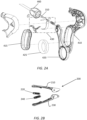
Figure 2A is an exploded view of the handle assembly of the grasping instrument ofFigure 1 ; -
Figure 2B is an exploded view of the jaw assembly of the grasping instrument ofFigure 1 ; -
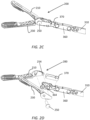
Figure 2C is an exploded view of the jaw assembly coupled to a distal end of an actuator having a tracked head member of the grasping instrument ofFigure 1 ; -
Figure 2D is an exploded view of the jaw assembly, tracked head member, and actuator ofFigure 2C ; -
Figure 3 is a side view of a jaw assembly of the grasping instrument ofFigure 1 with the jaw assembly in an open configuration; -
Figure 3A is a side view of a jaw assembly of the grasping instrument ofFigure 1 with the jaw assembly in an open configuration and with an outer tube and sleeve removed; -
Figure 4 is a side view of a jaw assembly of the grasping instrument ofFigure 1 with the jaw assembly in a partially closed configuration; -
Figure 4A is a side view of a jaw assembly of the grasping instrument ofFigure 1 with the jaw assembly in a partially closed configuration and with an outer tube and sleeve removed; -
Figure 5 is a side view of a jaw assembly of the grasping instrument ofFigure 1 with the jaw assembly in a closed configuration; -
Figure 5A is a side view of a jaw assembly of the grasping instrument ofFigure 1 with the jaw assembly in a closed configuration and with an outer tube and sleeve removed; -
Figure 6 is a partial cut away side view of a handle assembly of the grasping instrument ofFigure 1 positioned with the jaw assembly in an open configuration; -
Figure 7 is a partial cut away side view of a handle assembly of the grasping instrument ofFigure 1 positioned with the jaw assembly in a partially closed configuration; -
Figure 8 is a partial cut away side view of a handle assembly of the grasping instrument ofFigure 1 positioned with the jaw assembly in a closed configuration with a latch mechanism engaged in a latched configuration; -
Figure 9 is a partial cut away side view of a handle assembly of the grasping instrument ofFigure 1 positioned with the jaw assembly in a closed configuration with a latch mechanism engaged in an unlatched configuration; -
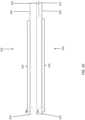
Figure 10 is a side view of an actuator of shaft assembly of the grasping instrument ofFigure 1 in an undisturbed state and an extended state; -
Figure 11A is a side view of a portion of the actuator ofFigure 10 in the undisturbed state; -
Figure 11B is a side view of a portion of the actuator ofFigure 10 in the extended state; and -
Figure 12 is a side view of various embodiments of actuator having an extension element. - With reference to
Figure 1 , an embodiment of asurgical grasping instrument 100 is illustrated. Thesurgical grasping instrument 100 can extend between a proximal end and a distal end and can comprise an end effector such as ajaw assembly 200 at the distal end, ashaft assembly 300 extending between the proximal end and the distal end, and ahandle assembly 400 at the proximal end. In some embodiments, thesurgical grasping instrument 100 can be configured for use in minimally-invasive surgical procedures such that it is sized and configured to be extended through a trocar cannula or other surgical access port. For example, in some embodiments, theshaft assembly 300 can comprise a generally tubular body having a smooth outer surface and an outer diameter sized for passage through a trocar cannula having a size classification to receive certain instruments such as, for example, a 12mm trocar, a 10mm trocar, and a 5mm trocar. In other embodiments, certain aspects of the surgical instruments described herein can be adapted for use with surgical access ports having different sizes or in open surgical procedures. - With reference to
Figure 2 andFigure 2B , an exploded view of thesurgical grasping instrument 100 ofFigure 1 is illustrated. In the illustrated embodiment, thejaw assembly 200 of thesurgical grasping instrument 100 comprises afirst jaw 210 coupled to asecond jaw 230 at apivot 250. Thus, by pivoting the first andsecond jaws jaw assembly 200 can be actuated between an open configuration in which thefirst jaw 210 is spaced from thesecond jaw 230 and a closed configuration in which thefirst jaw 210 is approximated with thesecond jaw 230 to grasp an object such as tissue, vasculature, or another surgical instrument therebetween. - The
jaw assembly 200 can be configured to reduce the potential for tissue trauma during use. For example, the first and/orsecond jaws Figure 2 andFigure 2B , thefirst jaw 210 comprises a firstatraumatic jaw pad 220 and thesecond jaw 230 comprises a secondatraumatic jaw pad 240. The first and secondatraumatic pads jaw assembly 200 can include pad-less first andsecond jaws - With reference to
Figure 2 ,Figure 2C, and Figure 2D , an exploded view of thesurgical grasping instrument 100 ofFigure 1 is illustrated. The first andsecond jaws pivot 250. An actuation post orpin 254 protrudes from each of the first andsecond jaws pivot 250. Thejaw assembly 200 is coupled to the distal end of theactuator 310 by ahead member 360, which is positioned between proximal ends of each of the first andsecond jaws head member 360 has atrack 364 formed therein. The actuation posts orpins 254 of each of the first andsecond jaws respective tracks 364 such that proximal and distal movements of theactuator 310 andhead member 360 with respect to the outer tube of the shaft moves theactuation pins 254 to open and close the first andsecond jaws shim 370 can be positioned at the distal end of thehead member 360 to maintain a desired spacing of thejaw assembly 200 andhead member 360 within the outer tube. Theshim 370 can have a saddle configuration positioned astride thehead member 360 and proximal ends of the first andsecond jaws pin 254 to become disengaged from thetrack 364 under load. - With continued reference to
Figure 2 , theelongate shaft assembly 300 comprises anactuator 310, anouter tube 330 and adielectric sleeve 340. The actuator can be slidably positioned within theouter tube 330. Thedielectric sleeve 340 can be disposed around an outer surface of theouter tube 330 and provide electrical insulation for theelongate shaft assembly 300. Theactuator 310 comprises a substantially planar member extending generally longitudinally between aproximal end 312 and adistal end 314. The substantially planar geometry of theactuator 310 is defined by a length between theproximal end 312 and thedistal end 314, a height orthogonal to the length, and a width orthogonal to both the length and the height. The width is substantially smaller than the height and the length. In accordance with the present invention, theactuator 310 comprises a stack of a plurality of actuator strips, such as, for example, two actuator strips to provide anactuator 310 having desired stiffness, extension, and fatigue life characteristics. - With continued reference to
Figure 2 andFigure 2A , thehandle assembly 400 comprises a housing formed of a pair of housing halves that define astationary handle 410, amovable handle 420 pivotably coupled to thestationary handle 410 at a pivot pin of alocking mechanism 430, and arotation knob 460. Thestationary handle 410 can be contoured to be grasped in the fingers of a user's hand and themovable handle 420 can include a thumb ring to be engaged by a user's thumb and moved by flexion and extension of the user's thumb. It is contemplated that other configurations of handle assembly can be used with the elongate shaft assemblies and end effector assemblies described herein. - With reference to
Figure 3 - Figure 5 and Figure 3A - Figure 5A, thejaw assembly 200 of the surgical grasping instrument is illustrated in open (Figure 3 andFigure 3A ), partially closed (Figure 4 andFigure 4A ), and closed configurations (Figure 5 andFigure 5A ). As illustrated inFigures 3 and3A , with thejaw assembly 200 in the open configuration, thefirst jaw 210 is spaced from thesecond jaw 230 such that a user can position the surgical grasping instrument in a surgical site with an object to be grasped positioned between the first andsecond jaws first jaw 210 and thesecond jaw 230 are pivotably coupled to one another at apivot 250 such as a linkage rivet, pin, or other pivotable assembly. - With continued reference to
Figure 3 andFigure 3A , thepivot 250 is also coupled to theouter tube 330 of theelongate shaft assembly 300 at the distal end of theelongate shaft assembly 300. Theelongate shaft assembly 300 can further comprise ahead member 360 that engages the first andsecond jaws jaw assembly 200 at engagement locations proximal thepivot 250. For example, the first andsecond jaws elongate shaft assembly 300 at a location proximal thepivot 250, and thehead member 360 can include a first groove, slot, or track 364 positioned to receive the actuation pin of thefirst jaw 210 and a second groove, slot, or track formed therein positioned to receive the actuation pin of thesecond jaw 230. The first track and the second track can extend transversely relative to the central longitudinal axis of theelongate shaft assembly 300 such that proximal and distal movement of thehead member 360 pivots the first andsecond jaws pivot 250. - With continued reference to
Figure 3 andFigure 3A , theelongate shaft assembly 300 can further include a jaw support member such as at least one shim member positioned within theouter tube 330 at the distal end to longitudinally align and maintain spacing of thehead member 360 and thejaw assembly 200 relative to the central longitudinal axis. Theelongate shaft assembly 300 can include aseal element 350 disposed between thehead member 360 and an inner surface of theouter tube 330 to prevent fluid and gas ingress or leakage from a surgical site into the elongate shaft assembly. For example, theelongate shaft assembly 300 can comprise an O-ring disposed retained by a groove in thehead member 360. - With continued reference to
Figure 3 andFigure 3A , a proximal end of thehead member 360 can be coupled to a distal end of theactuator 310. The proximal end of thehead member 360 and the distal end of theactuator 310 can be configured to provide a coupling that is rotatable about the central longitudinal axis of theelongate shaft assembly 300. For example, as illustrated, the proximal end of thehead member 360 comprises a protrudingannular post 362, and thedistal end 314 of theactuator 310 can comprise a cutout sized and configured to receive theannular post 362 and allow rotation of thejaw assembly 200 relative to the central longitudinal axis of theelongate shaft assembly 300. As further described with reference toFigure 6 , rotation of therotation knob 460 of thehandle assembly 400 can thus rotate theouter tube 330 of theelongate shaft assembly 300 to rotate thejaw assembly 200 to a desired orientation relative to the central longitudinal axis. - With continued reference to
Figure 3 andFigure 3A , thehead member 360 can be formed by a metal injection molding (MIM) process. Advantageously, this MIM process can allow the efficient, rapid manufacture of ahead member 360 of a metallic material having desirable strength and fatigue life characteristics and being formed to have desired geometric features, with integrated tracks or slots to engage thejaw assembly 200 and a post or positioning pin to engage theactuator 310 as described above. Alternatively, thehead member 360 can be formed of a metallic material that has been cast, machined, or otherwise processed to have the desired geometry, or thehead member 360 can be formed of a non-metallic material. - With reference to
Figure 4 andFigure 4A , here ajaw assembly 200 is illustrated in a partially closed configuration. As illustrated, proximal translation of theactuator 310 along the central longitudinal axis pivots thefirst jaw 210 and thesecond jaw 230 relative to one another to approximate thefirst jaw pad 220 and thesecond jaw pad 240. - With continued reference to
Figure 4 andFigure 4A , thefirst jaw 210 and thesecond jaw 230 have the same geometric features and pivot about the same pivot axis, which extends transversely to the central longitudinal axis. The pivot axis of the first andsecond jaws first jaw 210 has a generally elongate configuration defining a first jaw axis, and thesecond jaw 230 has a generally elongate configuration defining a second jaw axis. Proximal translation of theactuator 310 pivots the first andsecond jaws - With reference to
Figures 5 and5A , here ajaw assembly 200 is illustrated in a closed configuration. In the closed configuration, thefirst jaw 210 and thesecond jaw 230 are approximated such that thefirst jaw pad 220 is adjacent thesecond jaw pad 240 or separated by an object being grasped. As noted above, thefirst jaw pad 220 andsecond jaw pad 240 can be formed of a material selected to be atraumatic to tissue grasped therebetween. Moreover, thefirst jaw pad 220 andsecond jaw pad 240 can be disposed over a relatively large surface area relative to thefirst jaw 210 and thesecond jaw 230. For example, desirably, the first andsecond jaw pads second jaws pivot 250. More desirably, thejaw pads second jaws pivot 250. Advantageously, this relatively large atraumatic contact surface can distribute pressure applied to a grasped object over a large surface area to reduce the risk of trauma to grasped tissue. Moreover, the first andsecond jaw pads second jaws second jaw pads second jaw pads - With continued reference to
Figure 5 , thejaw assembly 200, the first andsecond jaws second jaws second jaw pads second jaws second jaw pads second jaws second jaw pads second jaw pads - With reference to
Figure 6 , here thehandle assembly 400 for the surgical graspinginstruments 100 described herein is illustrated. As illustrated, themovable handle 420 is spaced from thestationary handle 410 to position thejaw assembly 200 in an open configuration, as illustrated inFigure 3 . Desirably, thestationary handle 410 can have an ergonomic finger grip comprising an elastomeric finger grip insert 415 (Figure 2 ) removably positioned in the grip to provide a soft touch surface for a user. Likewise, a thumb ring of themovable handle 420 can comprise an elastomeric thumb ring insert 425 (Figure 2 ) removably positioned in the thumb ring to provide a soft touch surface for a user. A user can additionally rotaterotation knob 460 relative to thehandle assembly 400 to rotate theouter tube 330 relative to thehandle assembly 400. For example, thehandle assembly 400 can be configured with an ergonomic profile such that a user's index finger can easily be extended to rotate therotation knob 460. This rotation can orient thejaw assembly 200 coupled to theouter tube 330 in a desired orientation about tissue, vasculature, or another object to be grasped. - With reference to
Figure 7 , thehandle assembly 400 is illustrated in a partially closed configuration corresponding to thejaw assembly 200 in a partially closed configuration as illustrated inFigure 4 . In the partially closed configuration, themovable handle 420 is pivoted relative to thestationary handle 410 about the pivot pin of thelocking mechanism 430. The movable handle extends from afirst end 422 having the thumb ring to asecond end 424. The pivot pin of thelocking mechanism 430 is disposed between thefirst end 422 and thesecond end 424. Thesecond end 424 of themovable handle 420 is coupled to theproximal end 312 of theactuator 310. Theproximal end 312 of theactuator 310 can comprise aproximal coupler 313 such as a recess, bore, slot, or other feature that is configured to be coupled to with thesecond end 424 of themovable handle 420 and allow the transfer of force therebetween. In the illustrated embodiment, the proximal coupler comprises a bore that can receive a post protruding from thesecond end 424 of themovable handle 420 or can be coupled thereto by a coupling pin or rivet. Thus, as themovable handle 420 is pivoted about the pivot pin of thelocking mechanism 430, theactuator 310 is pulled proximally with respect to the central longitudinal axis. This proximal movement likewise moves thehead member 360 of theelongate shaft assembly 300 proximally to close thejaw assembly 200, as shown inFigure 4 . - With reference to
Figure 8 and Figure 9 , further movement of themovable handle 420 can further actuate the surgical grasping instrument to move thejaw assembly 200 to a closed configuration as shown inFigure 5 . Thehandle assembly 400 further comprises the locking mechanism therein to maintain themovable handle 420 in a desired position relative to thestationary handle 410. Thelocking mechanism 430 can comprise atrigger lock 440 and alock release 450 that are actuated by a user to latch and unlatch the locking mechanism. - With continued reference to
Figure 8 and Figure 9 , thelocking mechanism 430 is illustrated in latched (Figure 8 ) and unlatched (Figure 9 ) configurations. Thetrigger lock 440 of thelocking mechanism 430 extends from a first end having atrigger portion 444 extending adjacent thestationary handle 410 to a second end having a lockingportion 442 and positioned within thehandle assembly 400 adjacent theactuator 310. Theactuator 310 can have an engagement surface such as a latch recess formed therein and sized and configured to be selectively engaged by the lockingportion 442 of thetrigger lock 440 when thelocking mechanism 430 is in a latched configuration. Thelocking mechanism 430 can further comprise alocking spring 446 within the handle assembly to bias the lockingportion 442 of thetrigger lock 440 to maintain the engagement of the lockingportion 442 with the latch recess when thelocking mechanism 430 is in the latched configuration. - With reference to
Figure 8 , with thelocking mechanism 430 in a latched configuration, the lockingportion 442 of thetrigger lock 440 is positioned and oriented to restrict the actuator 310 from freely translating proximally and distally with respect to the central longitudinal axis. For example, the lockingportion 442 can comprise a passage or generally rectangular window formed therein through which theactuator 310 can freely translate when the lockingportion 442 is oriented generally perpendicularly to the actuator 310 (as illustrated inFigure 9 ) and which engages theactuator 310 when passage of the locking portion is misaligned with an axis perpendicular to the longitudinal axis of the actuator (Figure 8 ). The lockingspring 446 biases the lockingportion 442 of thetrigger lock 440 into binding engagement with theactuator 310 once thelock release 450 has been depressed to allow thetrigger lock 440 to separate from thestationary handle 410. Thus, this engagement between thetrigger lock 440 andactuator 310 locks thejaw assembly 200 in a desired position. - The
trigger lock 440 of thelocking mechanism 430 may define a reverse limit for thejaw assembly 220 preventing attempts by thejaw assembly 220 to revert from the closed position to the open position beyond the point defined by thelocking mechanism 430. However, the restrictions imposed by thetrigger lock 440 may not define a forward limit corresponding to an extent thejaw assembly 220 compresses the tissue in the closed position. - With reference to
Figure 9 , when a user desires to reposition the first and second jaws to grasp tissue specimens, themovable handle 420 can be moved to a desired position such as a partially closed or closed position with thelocking mechanism 430 in an unlatched configuration having thetrigger lock 440 approximated with thestationary handle 410 by latching engagement with thelock release 450. As illustrated, an end of thetrigger portion 444 can be advanced over thelock release 450 and maintained adjacent thestationary handle 410 by thelock release 450. With thetrigger lock 440 positioned adjacent thestationary handle 410, the lockingportion 442 of thetrigger lock 440 is oriented to allow free translation ofactuator 310 through the passage formed in the lockingportion 442 responsive to movement of themovable handle 420. - With continued reference to
Figure 9 , thelock release 450 can be pivotally coupled to thestationary handle 410 at alock release pivot 452. Thelock release 450 can be biased to maintain thetrigger portion 444 of thetrigger lock 440 adjacent thestationary handle 410. Thelock release 450 can be biased with alock release spring 454 disposed within the handle assembly. In is contemplated that in other embodiments, thelock release 450 can be formed of a flexible member extending from thestationary handle 410 with the desired bias and without a lock release pivot. When a user desires to engage thelocking mechanism 430 to maintain a fixed position of themovable handle 420,actuator 310, andjaw assembly 200, the user can depress thelock release 450 to overcome the bias of thelock release spring 454 and pivot thelock release 450 out of engagement with the end of thetrigger portion 444 of thetrigger lock 440. - With reference to
Figure 10 , an embodiment ofactuator 310 for use in the elongate shaft assemblies described herein is illustrated in undisturbed (upper) and extended (lower) states. Theactuator 310 has a substantially planar configuration with a significantly small width relative to its length and height. Advantageously, this planar configuration can be efficiently manufactured from a coil or sheet of a metallic material that can be heat treated to achieve desired tensile strength and durability characteristics. For example, in some embodiments, theactuator 310 can be stamped from a sheet of a metallic material having desired structural properties. In some embodiments, theactuator 310 can be formed from a metallic material such as a coil sheet of 17-7 PH stainless steel. In accordance with the present invention, the surgical grasping instrument has two or more stamped sheet actuators arranged in parallel in an adjoining orientation to achieve desired extension properties and durability characteristics while being relatively rapidly manufacturable by progressive stamping. Theactuator 310 can be configured to limit the force applied to an object being grasped, which advantageously can reduce the incidence of trauma to grasped tissue. - With continued reference to
Figure 10 , theactuator 310 comprises a segment formed to define anintegrated extension element 316. Advantageously, theextension element 316 can function as a force-limiting spring mechanism for theactuator 310 having an integrated construction that allows for low-cost, efficient manufacture of theactuator 310. As illustrated, theextension element 316 is disposed between theproximal end 312 anddistal end 314 of theactuator 310, with the remaining segments of the actuator defining a non-extending, orrigid elements 324. As illustrated, theextension element 316 can have a height orthogonal to the length of theactuator 310 that is smaller than a corresponding height of therigid elements 324. In the illustrated embodiment, theextension element 316 comprises a height that is approximately half of the height of therigid elements 324. - With reference to
Figure 10 ,Figure 11A, and Figure 11B here theextension element 316 comprises a geometric profile defining a desired spring constant for theactuator 310. For example, theextension element 316 comprises a plurality oflongitudinal sections 322 extending generally parallel to the central longitudinal axis, a plurality oftransverse sections 318 extending transverse to the central longitudinal axis, and a plurality ofbends 320 disposed between each longitudinal section of the plurality of longitudinal sections and an adjacent transverse section of the plurality of transverse sections. Eachbend 320 can comprise an arc segment having an inner radius and an outer radius. Theextension element 316 can comprise a plurality of extension sections 317with each individual extension section 317 a full section defined by a segment of a generally waveform-like profile extending from a peak to an adjacent peak (or a trough to an adjacent trough). Thus, eachextension section 317 can comprise a firstlongitudinal segment 322, afirst bend 320, a firsttransverse segment 318, asecond bend 321, a secondlongitudinal segment 323, athird bend 325, a secondtransverse segment 319, and afourth bend 327. - With continued reference to
Figure 10 ,Figure 11A, and Figure 11B , when a tensile force is applied to theactuator 310, a distance (X) (Figure 11A ) between adjacentlongitudinal segments 322 will extend to an extended length (X+ΔX) (Figure 11B ) such that the overall length between theproximal end 312 and thedistal end 314 is extended (Figure 10 ). Thus, this extension characteristic of theactuator 310 can desirably limit a force applied by the jaw assembly of a surgical grasping instrument. In the event a user applies a relatively high force or attempts to grasp a relatively thick tissue sample, a portion of the applied force will extend the actuator, rather than being directly applied to grasped tissue. - With continued reference to
Figure 10 ,Figure 11A, and Figure 11B in certain embodiments, the dimensions of thelongitudinal segments 322, bends 320, andtransverse segments 318 can be sized and configured to provide anextension element 316 having a desired spring constant and resistance to fatigue. Theactuator 310 can be formed of a rigid material, such as a stainless-steel sheet material, which has elastic properties under controlled tensile loads. Theactuator 310 has a substantially planar configuration with a width or thickness dimension being significantly smaller than a height or length dimension. In certain embodiments, whereas the surgical grasping instrument is introduced within 5mm trocar delivery systems, the outer tube can have a maximum outer diameter of 5mm (0.197 inch) and a minimum inner diameter of 3.56mm (0.140 inch). In certain embodiments, theactuator 310 positioned within the outer tube can have a height between 4.82mm (.190 inch) and 2.54mm (.100 inch) and have a thickness between 0.254mm (.010 inch) and 2.79mm (.110 inch). Desirably, two actuators can have a combined thickness between 5.08mm (.020 inch) and 2.79mm (.110 inch). In certain embodiments, multiple actuators can be assembled together in parallel, having a combined thickness between 5.08mm (.020 inch) and 2.79mm (.110 inch). In certain embodiments, although the surgical grasping instrument is introduced within greater than 5mm trocar delivery systems, theactuator 310 can have a maximum height of 8.89mm (.350 inch) and have a thickness between 0.254mm (.010 inch) and .6.35mm (250 inch). In some embodiments for use with an instrument sized and configured for placement through a 5mm category access port such as a 5mm trocar, theactuator 310 can have a thickness of approximately 1.02mm (.040 inch). In certain embodiments, theactuator 310 can comprise a stack of two adjoining actuator members each having a thickness of approximately .020 inch. - With continued reference to
Figure 10 ,Figure 11A, and Figure 11B , theextension element 316 can comprise at least 20extension sections 317. Desirably, the extension element can comprise at least 30extension sections 317. More desirably, theextension element 316 can comprise at least 40extension sections 317. Theextension element 316 can comprise 48extension sections 317. While the illustrated embodiment includes a plurality ofextension sections 317 that each have a consistent geometry, repeating to form theextension element 316, theextension element 316 can be formed of various segment and bend geometries that have a variable pattern along a length of theactuator 310. - With continued reference to
Figure 10 ,Figure 11A, and Figure 11B , thebends 320 can have an arc geometry defined by an inner radius and an outer radius. Alternatively, thebends 320 can be formed by sections having sharp angles with no fillet or radii. The inner radius can be between about 0.508mm (0.02 inch) and 2.03mm (0.08 inch). Desirably, a full radius defined by the inner radius can be between approximately 2.45mm (0.05 inch) and 1.52mm (0.06 inch). In certain embodiments, the outer radius can be between approximately 6.10mm (0.024 inch) and 1.37mm (0.054 inch). In some embodiments, the inner radius is greater than the outer radius. In other embodiments, the inner radius is less than the outer radius. In certain embodiments, a full radius defined by the inner radius is approximately 1.27mm (0.05 inch) and the outer radius is approximately 1.12mm (0.044 inch). In other embodiments, a full radius defined by the inner radius is approximately 1.52mm (0.06 inch) and the outer radius is approximately 0.914mm (0.036 inch). - In certain embodiments, the inner and outer radii can be sized and configured to provide an
extension element 316 having a relatively constant width defined by a line tangent to an upper edge and a lower edge of theextension element 316. In certain embodiments, the width defined by the line tangent to the upper edge and the lower edge of theextension element 316 is between about 1.52mm (0.060 inch) and 2.03mm (0.080 inch). Desirably, the width of theextension element 316 defined by the tangent line can be between about 1.65mm (0.065 inch) and 1.90mm (0.075 inch). In certain embodiments, the width of theextension element 316 defined by the tangent line can be about 1.78mm (0.07 inches). - With continued reference to
Figure 10 ,Figure 11A, and Figure 11B , theextension element 316 of theactuator 310 can be spaced from thedistal end 314 by arigid element 324 defining a connector end with a straight section having a height greater than the width defined by the line tangent to the upper edge and the lower edge of theextension element 316. In some embodiments, theextension element 316 can be spaced apart from thedistal end 314 by at least 5.1mm (0.2 inch). In other embodiments, theextension element 316 can be spaced from thedistal end 314 by a connector end straight section having a minimal distance of as approximately 0.51mm (0.02 inch). - With continued reference to
Figure 10 ,Figure 11A, and Figure 11B , in certain embodiments, a total length of eachfull extension section 317 can be sized and configured to provide a desired spring constant and fatigue strength. In some embodiments, the length of eachfull extension section 317 can be between approximately 5.08mm (0.200 inch) and 9.14mm (0.360 inch). Desirably, the length of eachextension section 317 can be between approximately 6.10mm (0.240 inch) and 6.60mm (0.260 inch). In certain embodiments, each extension section can have a length of approximately 6.10mm (0.240 inch). In other embodiments, each extension section can have a length of approximately 6.60mm (0.260 inch). - With continued reference to
Figure 10 andFigure 11A , desirably, when a force applied to theactuator 310 by actuation of the movable handle is below a predetermined level, theactuator 310 translates within theouter tube 330 with theextension element 316 maintaining a constant length. Thus, with a relatively low force applied to theactuator 310, the actuator 310 functions as a solid rod actuator. Theactuator 310 has a first length along the central longitudinal axis that remains constant on translation with application of a relatively low force to move theactuator 330 as a solid rod. - With reference to
Figure 10 andFigure 11B , when a relatively high force is applied to theactuator 310, such as when a thick tissue specimen is inserted between the first and second jaws of the jaw assembly, theextension element 316 can stretch in response, thereby reducing the effective stroke length of theactuator 310 at thedistal end 314. In some embodiments, the actuator 310 functions as a spring-like actuator. Thus, upon application of a predetermined extension force, theactuator 310 extends to a second length greater than the first length. In this higher force loading condition, theactuator 310 both translates within theouter tube 330 and extends in length between theproximal end 312 and thedistal end 314. This reduced effective stroke length provided by extension of theextension element 316 advantageously limits the force applied by the end effector or jaw assembly and correspondingly reduces a risk of trauma to tissue grasped by the jaw assembly. Theactuator 310 provides this force limiting performance as an integral component without the added mechanical and manufacturing complexities and increased expenditures of one or more additional springs. Desirably, theextension element 316 of theactuator 310 is sized and configured to deform elastically when a relatively high force is applied thereto as illustrated inFigure 11B such that once the force is released, theactuator 310 returns to its original, undeformed state and length. - In a further embodiment, the
actuator 310 is also sized and configured to supplement the first and second jaws of the jaw assembly with force that was loaded into the actuator 310 (which caused theactuator 310 to deform elastically as described above). In some cases, the jaw assembly may be locked in a closed position with tissue that is being grasped between the first and second jaw. The extent that the jaw assembly is in contact with the tissue is based on the thickness and/or volume of the tissue being grasped as well as the pre-determined amount of force that is provided to the tissue. However, if the tissue deforms (e.g., as fluids leave or are pushed out of the cells associated with the grasped tissue) which causes the thickness and volume of tissue being initially grasped to decrease, the original contact between the tissue and the jaw assembly may no longer be possible. Furthermore, in a conventional surgical grasper with a rigid, non-elastic actuator, since the first and second jaws of the jaw assembly are locked, tissue deformation may prevent the jaw assembly from properly grasping the tissue possibly causing the contact with the tissue to become loose or even slip from the jaw assembly. - Desirably, the surgical grasping device described herein can provide a dynamic amount of force from the
actuator 310 in order to maintain constant and/or consistent contact with the tissue between the first and second jaws of the jaw assembly as the tissue deforms. The dynamic amount of force being provided to the jaw assembly is supplied from the excess force that was previously loaded into theactuator 310. As discussed above, theactuator 310 may extend from a first length to a second greater length when loading force being provided by the user (via the movable handle). As the thickness and volume of tissue that was initially grasped between the first and second jaws of the jaw assembly changes (e.g., via deformation), a response from theactuator 310 can provide the force that was loaded into theactuator 310 to the jaw assembly so that the first and second jaws are pivoted closer towards each other in order to maintain contact with the tissue. This force, as it leaves theactuator 310, causes theactuator 310 to retract from the second greater length back towards the first length. The response from theactuator 310 provides additional force to the first and second jaws as needed to maintain contact with the deforming/deformed tissue based on the extent the thickness and volume of the tissue changes over time. In this way, contact with the tissue, as the tissue deforms, can be made constant/consistent between the first and second jaws of the jaw assembly. - With reference to
Figure 10 andFigure 12 , various embodiments of theactuator 310 are illustrated having different lengths ofrigid element 324 adjacent the proximal end. As illustrated, theextension element 316 of theactuator 310 can be spaced from theproximal end 312 by arigid element 324 having a height greater than a width of theextension element 316 defined by a line tangent to the upper edge and the lower edge of theextension element 316. In certain embodiments, it can be desired that the length ofrigid element 324 adjacent the proximal end be relatively long to conform to surgical instruments having different dimensions or operational configurations. For example, as illustrated inFigure 12 , anextension element 316 having a substantially similar configuration can be used in each of a 35 cm length single-use grasper (uppermost illustrated actuator), a 45 cm single-use grasper (second actuator from top), a 38 cm reposable grasper shaft (third actuator from top), and a 45 cm reposable grasper shaft (lowermost actuator). Alternatively, by varying the length of theextension element 316 relative to the lengths of therigid elements 324 at the proximal anddistal ends 213, 314 of theactuator 310, desired extension properties of theactuator 310 can be achieved. - With reference to
Figure 10 - Figure 12 , the illustrated embodiments include aplanar actuator 310 with anextension element 316 integrally formed therewith. Advantageously, this planar actuator can provide manufacturing efficiencies and can fit within and be constrained for translation within a relatively small space, such as an elongate shaft assembly sized for insertion through a surgical access port for 5mm laparoscopic instruments. In other embodiments, it is contemplated that other actuator configurations can provide a desired integrated force-limiting extension element. - Although this application discloses certain preferred embodiments, the scope of the invention should be determined with reference to the following claims.
Claims (13)
- A surgical grasping instrument (100) comprising:a handle assembly (400) comprising:a stationary handle (410), anda movable handle (420) pivotably coupled to the stationary handle (410);an elongate shaft (300) extending distally from the handle assembly (400), wherein the elongate shaft (300) having a proximal end coupled to the handle assembly (410), a distal end opposite the proximal end, and a central longitudinal axis defined by the proximal end and the distal end, the elongate shaft (300) comprising:an outer tube (330), andan actuator (310) positioned longitudinally within the outer tube (330), wherein the actuator (310) having a sliding fit with the outer tube (330), and wherein the actuator (310) being responsive to pivotal movement of the movable handle (420); anda jaw assembly (200) at the distal end of the elongate shaft (300), wherein the jaw assembly (200) comprises a first jaw (210) and a second jaw (230), wherein the first jaw (210) and the second jaw (230) are pivotable between an open configuration of the jaw assembly and a closed configuration of the jaw assembly (200) responsive to pivotal movement of the movable handle (420),wherein the actuator (310) has a first length along the central longitudinal axis, and wherein the actuator (310) comprises an extension element (316) that lengthens the actuator (310) to a second length greater than the first length in response to a predetermined force applied to the actuator (310);characterised in that the actuator has a height, and a width, wherein the width is substantially smaller than the height such that the actuator has a planar profile and in that the actuator comprises a stack of two or more adjoining actuator members assembled together in parallel.
- The surgical grasping instrument (100) of claim 1, wherein the actuator (310) is formed of a material having elastic material properties during axial plane motion within the outer tube (330).
- The surgical grasping instrument (100) of claim 2, wherein the actuator (310) deforms elastically under reciprocating tensile and compressive stress loading in response to pivotal movement of the movable handle (420).
- The surgical grasping instrument (100) of claim 1, wherein the extension element (316) comprises:a plurality of longitudinal sections (322) extending generally parallel to the central longitudinal axis;a plurality of transverse sections (318) extending transverse to the central longitudinal axis; anda plurality of bends (320) disposed between each longitudinal section (322) of the plurality of longitudinal sections and an adjacent transverse section (318) of the plurality of transverse sections.
- The surgical grasping instrument (100) of claim 4, wherein the extension element (316) is defined by a repeating sequence of extension sections (317), each extension section comprising: a first longitudinal section, a first bend, a first transverse section, a second bend, a second longitudinal section, a third bend, a second transverse section, a fourth bend, and a third longitudinal section, and wherein the actuator (310) comprises at least 20 extension sections (317).
- The surgical grasping instrument of claim 1, wherein the extension element (316) deforms elastically in response to rectilinear tensile and compressive forces.
- The surgical grasping instrument (100) of claim 1, wherein the extension element (316) has a geometric profile that corresponds to a pre-defined spring constant, and wherein the actuator (310) is configured to limit an amount of force above a pre-determined threshold that is provided to the jaw assembly (200), the force being received via the handle assembly (400).
- The surgical grasping instrument (100) of claim 7, wherein the actuator (310) exhibits characteristics of a solid rod when the amount of force received from the handle assembly (400) is below the pre-determined threshold.
- The surgical grasping instrument (100) of claim 8, wherein the actuator (310) exhibits characteristics of a spring when an amount of force received from the handle assembly (400) is above the pre-determined threshold to limit the amount of force that is provided to the jaw assembly (200).
- The surgical grasping instrument (100) of claim 1, wherein an arrangement of the stack of actuator members provides one or more of a pre-determined extension property, a pre-determined durability property, a pre-determined resistance to fatigue, or a pre-determined spring constant.
- The surgical grasping instrument (100) of claim 10, wherein an arrangement of the stack of actuator members establishes a pre-determined limit to an amount of force that can be provided to the jaw assembly (200).
- The surgical grasping instrument (100) of claim 10, wherein the stack of actuator members comprises non-extending elements.
- The surgical grasping instrument (100) of claim 10, wherein the actuator (310) is configured to provide the jaw assembly (200) with a dynamic amount of force in response to deformation of tissue initially grasped by the jaw assembly (200) in a closed position, and wherein the dynamic amount of force provided by the actuator (310) configures the jaw assembly (200) to exhibit constant contact to the tissue initially grasped between the jaw assembly (200) as the tissue deforms over a period of time.
Priority Applications (1)
| Application Number | Priority Date | Filing Date | Title |
|---|---|---|---|
| EP24189265.2A EP4424265A3 (en) | 2018-11-15 | 2019-11-11 | Laparoscopic grasper with force-limiting grasping mechanism |
Applications Claiming Priority (2)
| Application Number | Priority Date | Filing Date | Title |
|---|---|---|---|
| US201862768018P | 2018-11-15 | 2018-11-15 | |
| PCT/US2019/060743 WO2020102086A1 (en) | 2018-11-15 | 2019-11-11 | Laparoscopic grasper with force-limiting grasping mechanism |
Related Child Applications (2)
| Application Number | Title | Priority Date | Filing Date |
|---|---|---|---|
| EP24189265.2A Division-Into EP4424265A3 (en) | 2018-11-15 | 2019-11-11 | Laparoscopic grasper with force-limiting grasping mechanism |
| EP24189265.2A Division EP4424265A3 (en) | 2018-11-15 | 2019-11-11 | Laparoscopic grasper with force-limiting grasping mechanism |
Publications (3)
| Publication Number | Publication Date |
|---|---|
| EP3880094A1 EP3880094A1 (en) | 2021-09-22 |
| EP3880094C0 EP3880094C0 (en) | 2024-08-28 |
| EP3880094B1 true EP3880094B1 (en) | 2024-08-28 |
Family
ID=68848365
Family Applications (2)
| Application Number | Title | Priority Date | Filing Date |
|---|---|---|---|
| EP24189265.2A Pending EP4424265A3 (en) | 2018-11-15 | 2019-11-11 | Laparoscopic grasper with force-limiting grasping mechanism |
| EP19818308.9A Active EP3880094B1 (en) | 2018-11-15 | 2019-11-11 | Laparoscopic grasper with force-limiting grasping mechanism |
Family Applications Before (1)
| Application Number | Title | Priority Date | Filing Date |
|---|---|---|---|
| EP24189265.2A Pending EP4424265A3 (en) | 2018-11-15 | 2019-11-11 | Laparoscopic grasper with force-limiting grasping mechanism |
Country Status (8)
| Country | Link |
|---|---|
| US (3) | US11596428B2 (en) |
| EP (2) | EP4424265A3 (en) |
| JP (2) | JP7511556B2 (en) |
| KR (2) | KR102944197B1 (en) |
| AU (2) | AU2019380263B2 (en) |
| CA (1) | CA3120184A1 (en) |
| ES (1) | ES2986422T3 (en) |
| WO (1) | WO2020102086A1 (en) |
Families Citing this family (3)
| Publication number | Priority date | Publication date | Assignee | Title |
|---|---|---|---|---|
| WO2020102086A1 (en) * | 2018-11-15 | 2020-05-22 | Applied Medical Resources Corporation | Laparoscopic grasper with force-limiting grasping mechanism |
| CN115005900B (en) * | 2022-08-09 | 2022-11-04 | 生一科技(北京)有限公司 | Minimally invasive surgery instrument assembly and minimally invasive surgery instrument |
| CN121793909A (en) * | 2023-07-16 | 2026-04-03 | 虚拟端口有限公司 | Surgical unit, and delivery unit and method for delivering a surgical unit |
Citations (1)
| Publication number | Priority date | Publication date | Assignee | Title |
|---|---|---|---|---|
| US20140358163A1 (en) * | 2011-07-11 | 2014-12-04 | EON Surgical Ltd. | Laparoscopic graspers |
Family Cites Families (95)
| Publication number | Priority date | Publication date | Assignee | Title |
|---|---|---|---|---|
| US3503398A (en) | 1965-09-10 | 1970-03-31 | American Hospital Supply Corp | Atraumatic clamp for vascular surgery |
| US3515139A (en) | 1966-08-29 | 1970-06-02 | Codman & Shurtleff | Atraumatic clamp |
| US3503396A (en) | 1967-09-21 | 1970-03-31 | American Hospital Supply Corp | Atraumatic surgical clamp |
| US3503397A (en) | 1967-09-21 | 1970-03-31 | American Hospital Supply Corp | Atraumatic surgical clamp |
| US3746002A (en) | 1971-04-29 | 1973-07-17 | J Haller | Atraumatic surgical clamp |
| US4120302A (en) | 1976-10-08 | 1978-10-17 | American Hospital Supply Corporation | Disposable pads for surgical instruments |
| US4483562A (en) * | 1981-10-16 | 1984-11-20 | Arnold Schoolman | Locking flexible shaft device with live distal end attachment |
| US4821719A (en) | 1984-12-03 | 1989-04-18 | Fogarty Thomas J | Cohesive-adhesive atraumatic clamp |
| US5626609A (en) | 1990-10-05 | 1997-05-06 | United States Surgical Corporation | Endoscopic surgical instrument |
| US5489292A (en) | 1990-10-05 | 1996-02-06 | United States Surgical Corporation | Endoscopic surgical instrument with grip enhancing means |
| US5395375A (en) * | 1992-11-18 | 1995-03-07 | Symbiosis Corporation | Arthroscopic surgical instruments |
| US5476479A (en) | 1991-09-26 | 1995-12-19 | United States Surgical Corporation | Handle for endoscopic surgical instruments and jaw structure |
| CA2075333C (en) * | 1991-10-18 | 2003-07-22 | Ernie Aranyi | Handle for endoscopic surgical instruments and jaw structure |
| US5314424A (en) | 1992-04-06 | 1994-05-24 | United States Surgical Corporation | Surgical instrument locking mechanism |
| US5251638A (en) * | 1992-04-16 | 1993-10-12 | Cordis Corporation | Biopsy forceps device having improved handle assembly |
| US5395367A (en) * | 1992-07-29 | 1995-03-07 | Wilk; Peter J. | Laparoscopic instrument with bendable shaft and removable actuator |
| CA2114330A1 (en) * | 1993-01-29 | 1994-07-30 | Smith & Nephew Endoscopy, Inc. | Rotatable curved instrument |
| JP3384581B2 (en) * | 1993-03-30 | 2003-03-10 | オリンパス光学工業株式会社 | Medical gripper |
| US5776146A (en) | 1993-10-20 | 1998-07-07 | Applied Medical Resources | Laparoscopic surgical clamp |
| US5776147A (en) | 1993-10-20 | 1998-07-07 | Applied Medical Resources Corporation | Laparoscopic surgical clamp |
| US5496333A (en) | 1993-10-20 | 1996-03-05 | Applied Medical Resources Corporation | Laparoscopic surgical clamp |
| JPH07265326A (en) * | 1994-03-31 | 1995-10-17 | Olympus Optical Co Ltd | Medical treatment device |
| US5591182A (en) | 1994-10-17 | 1997-01-07 | Applied Medical Resources Corporation | Atraumatic surgical clamping instrument |
| US5643248A (en) | 1995-02-07 | 1997-07-01 | Yoon; Inbae | Medical instrument with force limiting mechanism |
| US5626608A (en) * | 1996-03-29 | 1997-05-06 | United States Surgical Corporation | Surgical instrument having locking handle |
| US5735874A (en) | 1996-06-21 | 1998-04-07 | Ethicon Endo-Surgery, Inc. | Variable position handle locking mechanism |
| US20030236537A1 (en) | 1999-08-09 | 2003-12-25 | Applied Medical Resources Corporation | Surgical instruments with improved traction |
| JP2001510366A (en) | 1997-02-03 | 2001-07-31 | アプライド メディカル リソーセス コーポレイション | Surgical instruments with improved traction |
| US6579304B1 (en) | 1997-02-03 | 2003-06-17 | Applied Medical Resources Corporation | Surgical clamp with improved traction |
| US8092473B2 (en) | 1997-02-03 | 2012-01-10 | Applied Medical Resources Corporation | Surgical clamp with improved traction |
| FR2777443B1 (en) * | 1998-04-21 | 2000-06-30 | Tornier Sa | ANCILLARY FOR THE PLACEMENT AND REMOVAL OF AN IMPLANT AND MORE PARTICULARLY A SUTURE ANCHOR |
| DE29810958U1 (en) | 1998-06-19 | 1998-09-10 | Olympus Winter & Ibe Gmbh, 22045 Hamburg | Endoscopic shaft instrument |
| US6099539A (en) | 1998-07-27 | 2000-08-08 | Thomas J. Fogarty | Surgical clamp pad with interdigitating teeth |
| DE19855968C1 (en) * | 1998-12-04 | 2000-10-05 | Storz Karl Gmbh & Co Kg | Medical reed shaft instrument |
| DE59900101D1 (en) * | 1999-04-29 | 2001-06-28 | Storz Karl Gmbh & Co Kg | Medical instrument for tissue preparation |
| US6228104B1 (en) | 1999-06-18 | 2001-05-08 | Novare Surgical Systems, Inc. | Surgical clamp having replaceable pad |
| US6387112B1 (en) | 1999-06-18 | 2002-05-14 | Novare Surgical Systems, Inc. | Surgical clamp having replaceable pad |
| US6273902B1 (en) | 1999-06-18 | 2001-08-14 | Novare Surgical Systems, Inc. | Surgical clamp having replaceable pad |
| US6117158A (en) | 1999-07-07 | 2000-09-12 | Ethicon Endo-Surgery, Inc. | Ratchet release mechanism for hand held instruments |
| US6589259B1 (en) * | 1999-12-28 | 2003-07-08 | Karl Storz Gmbh & Co. Kg | Medical instrument, particularly a surgical instrument |
| US6719766B1 (en) | 2000-08-24 | 2004-04-13 | Novare Surgical Systems, Inc. | Surgical clamp pads having surface overlay |
| DE10110106B4 (en) * | 2001-03-02 | 2007-08-02 | Richard Wolf Gmbh | Surgical forceps |
| US10849681B2 (en) * | 2001-04-06 | 2020-12-01 | Covidien Ag | Vessel sealer and divider |
| US6942676B2 (en) | 2002-03-21 | 2005-09-13 | Novare Surgical Systems, Inc. | Surgical clamp pads with deflecting elements |
| US7291161B2 (en) | 2002-10-02 | 2007-11-06 | Atricure, Inc. | Articulated clamping member |
| US6874833B2 (en) | 2003-01-10 | 2005-04-05 | Glen S. Keith | Pickup tool with variable position limiting and variable axis of operation |
| US7182775B2 (en) | 2003-02-27 | 2007-02-27 | Microline Pentax, Inc. | Super atraumatic grasper apparatus |
| US8398632B1 (en) | 2003-06-10 | 2013-03-19 | Medtronic Cryocath Lp | Surgical clamp having treatment elements |
| US7044946B2 (en) | 2003-06-10 | 2006-05-16 | Cryocath Technologies Inc. | Surgical clamp having treatment elements |
| US7819860B2 (en) | 2003-06-10 | 2010-10-26 | Medtronic Cryocath Lp | Surgical clamp having trasmurality assessment capabilities |
| WO2005046491A1 (en) | 2003-11-12 | 2005-05-26 | Applied Medical Resources Corporation | Overmolded grasper jaw |
| US20050240219A1 (en) | 2004-04-22 | 2005-10-27 | Henry Kahle | Peripheral vascular occlusion devices |
| JP5009159B2 (en) | 2004-10-08 | 2012-08-22 | エシコン・エンド−サージェリィ・インコーポレイテッド | Ultrasonic surgical instrument |
| US7918848B2 (en) | 2005-03-25 | 2011-04-05 | Maquet Cardiovascular, Llc | Tissue welding and cutting apparatus and method |
| US8080004B2 (en) | 2005-10-26 | 2011-12-20 | Earl Downey | Laparoscopic surgical instrument |
| US7766910B2 (en) * | 2006-01-24 | 2010-08-03 | Tyco Healthcare Group Lp | Vessel sealer and divider for large tissue structures |
| AU2007257754A1 (en) | 2006-06-08 | 2007-12-21 | Bannerman, Brett | Medical device with articulating shaft |
| US8409244B2 (en) | 2007-04-16 | 2013-04-02 | Intuitive Surgical Operations, Inc. | Tool with end effector force limiter |
| US20080004655A1 (en) | 2006-07-03 | 2008-01-03 | Valentine International Ltd. | Automatic lock mechanism for bar clamp |
| US8795351B2 (en) * | 2007-04-13 | 2014-08-05 | C.R. Bard, Inc. | Migration resistant embolic filter |
| CN200973731Y (en) | 2007-05-29 | 2007-11-14 | 许林 | Vascular blocking clamp without generating wound |
| US8252021B2 (en) | 2007-11-16 | 2012-08-28 | Microline Surgical, Inc. | Fenestrated super atraumatic grasper apparatus |
| GB2460392B (en) | 2008-02-29 | 2012-08-01 | Surgical Innovations Ltd | Handle |
| WO2009132359A2 (en) | 2008-04-25 | 2009-10-29 | Downey Earl C | Laparoscopic surgical instrument |
| US8968355B2 (en) * | 2008-08-04 | 2015-03-03 | Covidien Lp | Articulating surgical device |
| US20110112366A1 (en) * | 2009-11-07 | 2011-05-12 | Nauman Basit | Laparoscopic instrument |
| US8523893B2 (en) * | 2010-09-30 | 2013-09-03 | Applied Medical Resources Corporation | Laparoscopic scissors |
| AU2011308701B2 (en) * | 2010-09-30 | 2013-11-14 | Ethicon Endo-Surgery, Inc. | Fastener system comprising a retention matrix and an alignment matrix |
| US8840639B2 (en) | 2010-10-29 | 2014-09-23 | Covidien Lp | Apparatus for performing an electrosurgical procedure |
| US8603134B2 (en) | 2011-01-14 | 2013-12-10 | Covidien Lp | Latch mechanism for surgical instruments |
| US9113940B2 (en) | 2011-01-14 | 2015-08-25 | Covidien Lp | Trigger lockout and kickback mechanism for surgical instruments |
| US20120296371A1 (en) | 2011-05-17 | 2012-11-22 | Tyco Healthcare Group Lp | Modular Shaft for Endoscopic Vessel Sealer and Divider |
| JP5848827B2 (en) * | 2011-09-15 | 2016-01-27 | テレフレックス メディカル インコーポレイテッドTeleflex Medical Incorporated | Manual surgical ligation clip applier |
| US8652165B2 (en) | 2012-04-25 | 2014-02-18 | Ethicon Endo-Surgery, Inc. | Toggling ergonomic surgical instrument |
| US8968311B2 (en) * | 2012-05-01 | 2015-03-03 | Covidien Lp | Surgical instrument with stamped double-flag jaws and actuation mechanism |
| US10058311B1 (en) * | 2013-10-09 | 2018-08-28 | Rogelio A. Insignares | Ergonomic multi-functional handle for use with a medical instrument |
| US9943325B2 (en) | 2013-11-26 | 2018-04-17 | Ethicon Llc | Handpiece and blade configurations for ultrasonic surgical instrument |
| US9757186B2 (en) * | 2014-04-17 | 2017-09-12 | Ethicon Llc | Device status feedback for bipolar tissue spacer |
| WO2016040038A1 (en) * | 2014-09-08 | 2016-03-17 | CARDIONOMIC, Inc. | Methods for electrical neuromodulation of the heart |
| US10206736B2 (en) * | 2015-03-13 | 2019-02-19 | Covidien Lp | Surgical forceps with scalpel functionality |
| US10159506B2 (en) * | 2015-03-16 | 2018-12-25 | Ethicon Llc | Methods and devices for actuating surgical instruments |
| US10828084B2 (en) * | 2015-05-22 | 2020-11-10 | Covidien Lp | Surgical instruments and methods for performing tonsillectomy, adenoidectomy, and other surgical procedures |
| JP6564668B2 (en) * | 2015-10-02 | 2019-08-21 | 国立大学法人九州大学 | manipulator |
| US10335129B2 (en) * | 2015-11-17 | 2019-07-02 | Ethicon Llc | Methods and devices for auto return of articulated end effectors |
| US10966717B2 (en) | 2016-01-07 | 2021-04-06 | Covidien Lp | Surgical fastener apparatus |
| GB201600546D0 (en) * | 2016-01-12 | 2016-02-24 | Gyrus Medical Ltd | Electrosurgical device |
| US9439647B1 (en) | 2016-03-02 | 2016-09-13 | Arthrogenx, LLC. | Suture passing instruments and methods |
| WO2017161049A1 (en) | 2016-03-15 | 2017-09-21 | The Regents Of The University Of California | Articulable endoscopic instruments |
| JP6916869B2 (en) * | 2017-04-17 | 2021-08-11 | オリンパス株式会社 | Power transmission mechanism and treatment tool |
| WO2018232128A1 (en) * | 2017-06-14 | 2018-12-20 | Epic Medical Concepts & Innovations, Inc. | Laparoscopic devices and related methods |
| US11278280B2 (en) * | 2018-03-28 | 2022-03-22 | Cilag Gmbh International | Surgical instrument comprising a jaw closure lockout |
| US10786299B2 (en) * | 2018-03-30 | 2020-09-29 | Gyrus Acmi, Inc. | Closure assembly that is laterally movable for selective locking |
| WO2020102086A1 (en) * | 2018-11-15 | 2020-05-22 | Applied Medical Resources Corporation | Laparoscopic grasper with force-limiting grasping mechanism |
| US11350957B2 (en) * | 2019-03-27 | 2022-06-07 | Gyms Acmi, Inc. | Laparoscopic forceps assembly for gripping and dissection |
| US11744603B2 (en) * | 2021-03-24 | 2023-09-05 | Cilag Gmbh International | Multi-axis pivot joints for surgical instruments and methods for manufacturing same |
-
2019
- 2019-11-11 WO PCT/US2019/060743 patent/WO2020102086A1/en not_active Ceased
- 2019-11-11 EP EP24189265.2A patent/EP4424265A3/en active Pending
- 2019-11-11 JP JP2021525830A patent/JP7511556B2/en active Active
- 2019-11-11 EP EP19818308.9A patent/EP3880094B1/en active Active
- 2019-11-11 US US16/679,664 patent/US11596428B2/en active Active
- 2019-11-11 AU AU2019380263A patent/AU2019380263B2/en active Active
- 2019-11-11 KR KR1020217018192A patent/KR102944197B1/en active Active
- 2019-11-11 CA CA3120184A patent/CA3120184A1/en active Pending
- 2019-11-11 KR KR1020257030273A patent/KR20250138289A/en active Pending
- 2019-11-11 ES ES19818308T patent/ES2986422T3/en active Active
-
2023
- 2023-01-18 US US18/156,314 patent/US12042165B2/en active Active
-
2024
- 2024-06-25 JP JP2024101897A patent/JP2024133070A/en active Pending
- 2024-07-10 US US18/769,199 patent/US20240358390A1/en active Pending
-
2025
- 2025-08-18 AU AU2025217431A patent/AU2025217431A1/en active Pending
Patent Citations (1)
| Publication number | Priority date | Publication date | Assignee | Title |
|---|---|---|---|---|
| US20140358163A1 (en) * | 2011-07-11 | 2014-12-04 | EON Surgical Ltd. | Laparoscopic graspers |
Also Published As
| Publication number | Publication date |
|---|---|
| EP3880094C0 (en) | 2024-08-28 |
| US20240358390A1 (en) | 2024-10-31 |
| KR102944197B1 (en) | 2026-03-27 |
| AU2019380263B2 (en) | 2025-05-22 |
| KR20250138289A (en) | 2025-09-19 |
| US20200155185A1 (en) | 2020-05-21 |
| AU2019380263A1 (en) | 2021-05-20 |
| WO2020102086A1 (en) | 2020-05-22 |
| JP7511556B2 (en) | 2024-07-05 |
| KR20210092257A (en) | 2021-07-23 |
| EP4424265A3 (en) | 2024-11-20 |
| CA3120184A1 (en) | 2020-05-22 |
| AU2025217431A1 (en) | 2025-09-04 |
| EP4424265A2 (en) | 2024-09-04 |
| US20230149037A1 (en) | 2023-05-18 |
| JP2022507329A (en) | 2022-01-18 |
| US11596428B2 (en) | 2023-03-07 |
| EP3880094A1 (en) | 2021-09-22 |
| JP2024133070A (en) | 2024-10-01 |
| ES2986422T3 (en) | 2024-11-11 |
| US12042165B2 (en) | 2024-07-23 |
Similar Documents
| Publication | Publication Date | Title |
|---|---|---|
| US12042165B2 (en) | Laparoscopic grasper with force-limiting grasping mechanism | |
| US8568443B1 (en) | Surgical grapser tool and actuation mechanism | |
| EP2140818B1 (en) | Medical instrument for grasping an object, in particular needle holder | |
| US20200029988A1 (en) | Single port instruments | |
| US9770574B2 (en) | Torque device and securement mechanism | |
| US20160270808A1 (en) | Anvil grasper | |
| US9743945B2 (en) | Laparoscopic scissors | |
| US20250375201A1 (en) | Clip retention for surgical clip applier | |
| GB2489492A (en) | Positioning assembly for a surgical instrument | |
| US8523893B2 (en) | Laparoscopic scissors | |
| US20060079931A1 (en) | Surgical deep needle driver |
Legal Events
| Date | Code | Title | Description |
|---|---|---|---|
| STAA | Information on the status of an ep patent application or granted ep patent |
Free format text: STATUS: UNKNOWN |
|
| STAA | Information on the status of an ep patent application or granted ep patent |
Free format text: STATUS: THE INTERNATIONAL PUBLICATION HAS BEEN MADE |
|
| PUAI | Public reference made under article 153(3) epc to a published international application that has entered the european phase |
Free format text: ORIGINAL CODE: 0009012 |
|
| STAA | Information on the status of an ep patent application or granted ep patent |
Free format text: STATUS: REQUEST FOR EXAMINATION WAS MADE |
|
| 17P | Request for examination filed |
Effective date: 20210415 |
|
| AK | Designated contracting states |
Kind code of ref document: A1 Designated state(s): AL AT BE BG CH CY CZ DE DK EE ES FI FR GB GR HR HU IE IS IT LI LT LU LV MC MK MT NL NO PL PT RO RS SE SI SK SM TR |
|
| DAV | Request for validation of the european patent (deleted) | ||
| DAX | Request for extension of the european patent (deleted) | ||
| STAA | Information on the status of an ep patent application or granted ep patent |
Free format text: STATUS: EXAMINATION IS IN PROGRESS |
|
| 17Q | First examination report despatched |
Effective date: 20230609 |
|
| GRAP | Despatch of communication of intention to grant a patent |
Free format text: ORIGINAL CODE: EPIDOSNIGR1 |
|
| STAA | Information on the status of an ep patent application or granted ep patent |
Free format text: STATUS: GRANT OF PATENT IS INTENDED |
|
| INTG | Intention to grant announced |
Effective date: 20240325 |
|
| GRAS | Grant fee paid |
Free format text: ORIGINAL CODE: EPIDOSNIGR3 |
|
| GRAA | (expected) grant |
Free format text: ORIGINAL CODE: 0009210 |
|
| STAA | Information on the status of an ep patent application or granted ep patent |
Free format text: STATUS: THE PATENT HAS BEEN GRANTED |
|
| AK | Designated contracting states |
Kind code of ref document: B1 Designated state(s): AL AT BE BG CH CY CZ DE DK EE ES FI FR GB GR HR HU IE IS IT LI LT LU LV MC MK MT NL NO PL PT RO RS SE SI SK SM TR |
|
| REG | Reference to a national code |
Ref country code: CH Ref legal event code: EP |
|
| REG | Reference to a national code |
Ref country code: DE Ref legal event code: R096 Ref document number: 602019057991 Country of ref document: DE |
|
| REG | Reference to a national code |
Ref country code: IE Ref legal event code: FG4D |
|
| U01 | Request for unitary effect filed |
Effective date: 20240828 |
|
| U07 | Unitary effect registered |
Designated state(s): AT BE BG DE DK EE FI FR IT LT LU LV MT NL PT RO SE SI Effective date: 20240903 |
|
| REG | Reference to a national code |
Ref country code: ES Ref legal event code: FG2A Ref document number: 2986422 Country of ref document: ES Kind code of ref document: T3 Effective date: 20241111 |
|
| U20 | Renewal fee for the european patent with unitary effect paid |
Year of fee payment: 6 Effective date: 20241127 |
|
| PG25 | Lapsed in a contracting state [announced via postgrant information from national office to epo] |
Ref country code: NO Free format text: LAPSE BECAUSE OF FAILURE TO SUBMIT A TRANSLATION OF THE DESCRIPTION OR TO PAY THE FEE WITHIN THE PRESCRIBED TIME-LIMIT Effective date: 20241128 |
|
| PG25 | Lapsed in a contracting state [announced via postgrant information from national office to epo] |
Ref country code: GR Free format text: LAPSE BECAUSE OF FAILURE TO SUBMIT A TRANSLATION OF THE DESCRIPTION OR TO PAY THE FEE WITHIN THE PRESCRIBED TIME-LIMIT Effective date: 20241129 Ref country code: PL Free format text: LAPSE BECAUSE OF FAILURE TO SUBMIT A TRANSLATION OF THE DESCRIPTION OR TO PAY THE FEE WITHIN THE PRESCRIBED TIME-LIMIT Effective date: 20240828 |
|
| PG25 | Lapsed in a contracting state [announced via postgrant information from national office to epo] |
Ref country code: IS Free format text: LAPSE BECAUSE OF FAILURE TO SUBMIT A TRANSLATION OF THE DESCRIPTION OR TO PAY THE FEE WITHIN THE PRESCRIBED TIME-LIMIT Effective date: 20241228 |
|
| PG25 | Lapsed in a contracting state [announced via postgrant information from national office to epo] |
Ref country code: HR Free format text: LAPSE BECAUSE OF FAILURE TO SUBMIT A TRANSLATION OF THE DESCRIPTION OR TO PAY THE FEE WITHIN THE PRESCRIBED TIME-LIMIT Effective date: 20240828 |
|
| PG25 | Lapsed in a contracting state [announced via postgrant information from national office to epo] |
Ref country code: RS Free format text: LAPSE BECAUSE OF FAILURE TO SUBMIT A TRANSLATION OF THE DESCRIPTION OR TO PAY THE FEE WITHIN THE PRESCRIBED TIME-LIMIT Effective date: 20241128 |
|
| PG25 | Lapsed in a contracting state [announced via postgrant information from national office to epo] |
Ref country code: RS Free format text: LAPSE BECAUSE OF FAILURE TO SUBMIT A TRANSLATION OF THE DESCRIPTION OR TO PAY THE FEE WITHIN THE PRESCRIBED TIME-LIMIT Effective date: 20241128 Ref country code: PL Free format text: LAPSE BECAUSE OF FAILURE TO SUBMIT A TRANSLATION OF THE DESCRIPTION OR TO PAY THE FEE WITHIN THE PRESCRIBED TIME-LIMIT Effective date: 20240828 Ref country code: NO Free format text: LAPSE BECAUSE OF FAILURE TO SUBMIT A TRANSLATION OF THE DESCRIPTION OR TO PAY THE FEE WITHIN THE PRESCRIBED TIME-LIMIT Effective date: 20241128 Ref country code: IS Free format text: LAPSE BECAUSE OF FAILURE TO SUBMIT A TRANSLATION OF THE DESCRIPTION OR TO PAY THE FEE WITHIN THE PRESCRIBED TIME-LIMIT Effective date: 20241228 Ref country code: HR Free format text: LAPSE BECAUSE OF FAILURE TO SUBMIT A TRANSLATION OF THE DESCRIPTION OR TO PAY THE FEE WITHIN THE PRESCRIBED TIME-LIMIT Effective date: 20240828 Ref country code: GR Free format text: LAPSE BECAUSE OF FAILURE TO SUBMIT A TRANSLATION OF THE DESCRIPTION OR TO PAY THE FEE WITHIN THE PRESCRIBED TIME-LIMIT Effective date: 20241129 |
|
| PG25 | Lapsed in a contracting state [announced via postgrant information from national office to epo] |
Ref country code: SM Free format text: LAPSE BECAUSE OF FAILURE TO SUBMIT A TRANSLATION OF THE DESCRIPTION OR TO PAY THE FEE WITHIN THE PRESCRIBED TIME-LIMIT Effective date: 20240828 |
|
| PG25 | Lapsed in a contracting state [announced via postgrant information from national office to epo] |
Ref country code: CZ Free format text: LAPSE BECAUSE OF FAILURE TO SUBMIT A TRANSLATION OF THE DESCRIPTION OR TO PAY THE FEE WITHIN THE PRESCRIBED TIME-LIMIT Effective date: 20240828 |
|
| PG25 | Lapsed in a contracting state [announced via postgrant information from national office to epo] |
Ref country code: SK Free format text: LAPSE BECAUSE OF FAILURE TO SUBMIT A TRANSLATION OF THE DESCRIPTION OR TO PAY THE FEE WITHIN THE PRESCRIBED TIME-LIMIT Effective date: 20240828 |
|
| REG | Reference to a national code |
Ref country code: CH Ref legal event code: PL |
|
| PLBE | No opposition filed within time limit |
Free format text: ORIGINAL CODE: 0009261 |
|
| STAA | Information on the status of an ep patent application or granted ep patent |
Free format text: STATUS: NO OPPOSITION FILED WITHIN TIME LIMIT |
|
| PG25 | Lapsed in a contracting state [announced via postgrant information from national office to epo] |
Ref country code: MC Free format text: LAPSE BECAUSE OF FAILURE TO SUBMIT A TRANSLATION OF THE DESCRIPTION OR TO PAY THE FEE WITHIN THE PRESCRIBED TIME-LIMIT Effective date: 20240828 |
|
| REG | Reference to a national code |
Ref country code: CH Ref legal event code: PL |
|
| PG25 | Lapsed in a contracting state [announced via postgrant information from national office to epo] |
Ref country code: CH Free format text: LAPSE BECAUSE OF NON-PAYMENT OF DUE FEES Effective date: 20241130 |
|
| 26N | No opposition filed |
Effective date: 20250530 |
|
| U20 | Renewal fee for the european patent with unitary effect paid |
Year of fee payment: 7 Effective date: 20251126 |
|
| PGFP | Annual fee paid to national office [announced via postgrant information from national office to epo] |
Ref country code: GB Payment date: 20251127 Year of fee payment: 7 |
|
| PGFP | Annual fee paid to national office [announced via postgrant information from national office to epo] |
Ref country code: IE Payment date: 20251127 Year of fee payment: 7 |
|
| PGFP | Annual fee paid to national office [announced via postgrant information from national office to epo] |
Ref country code: ES Payment date: 20251201 Year of fee payment: 7 |
|
| PG25 | Lapsed in a contracting state [announced via postgrant information from national office to epo] |
Ref country code: HU Free format text: LAPSE BECAUSE OF FAILURE TO SUBMIT A TRANSLATION OF THE DESCRIPTION OR TO PAY THE FEE WITHIN THE PRESCRIBED TIME-LIMIT; INVALID AB INITIO Effective date: 20191111 |
|
| PG25 | Lapsed in a contracting state [announced via postgrant information from national office to epo] |
Ref country code: CY Free format text: LAPSE BECAUSE OF FAILURE TO SUBMIT A TRANSLATION OF THE DESCRIPTION OR TO PAY THE FEE WITHIN THE PRESCRIBED TIME-LIMIT; INVALID AB INITIO Effective date: 20191111 |